topic 2 machining 160214
TRANSCRIPT

BDA 3052 Manufacturing Technology
Material Removal Process (Metal
Machining Process)
1.1 Theory of Metal Cutting
overview, theory of chip formation, force &
merchant equation, power & energy, cutting
temperature
1.2 Machining Operations and Machine Tools
turning, drilling, milling, machine centers,
cutting tool technology

BDA 3052 Manufacturing Technology
Material Removal ProcessesIntroduction
It is shaping operations, it remove material from a
starting workpart so the remaining part has the
desired geometry
Divided into three main groups:
1) Machining – material removal by a sharp
cutting tool, e.g., turning, milling, drilling
2) Abrasive processes – material removal by hard,
abrasive particles, e.g., grinding
3) Nontraditional processes - various energy
forms other than sharp cutting tool to remove
material

BDA 3052 Manufacturing Technology
Why Machining is Important
Variety of work materials can be machined
Most frequently used to cut metals
Variety of part shapes and special geometric
features possible, such as:
Screw threads
Accurate round holes
Very straight edges and surfaces
Good dimensional accuracy and surface finish

BDA 3052 Manufacturing Technology
Disadvantages with Machining
Wasteful of material
Chips generated in machining are wasted
material, at least in the unit operation
Time consuming
A machining operation generally takes more
time to shape a given part than alternative
shaping processes, such as casting, powder
metallurgy, or forming

BDA 3052 Manufacturing Technology
Machining in Manufacturing Sequence
Generally performed after other manufacturing
processes, such as casting, forging, and bar
drawing
Other processes create the general shape of
the starting workpart
Machining provides the final shape,
dimensions, finish, and special geometric
details that other processes cannot create

BDA 3052 Manufacturing Technology
Machining
Nomenclature of single point tool

BDA 3052 Manufacturing Technology
Seven elements of single-point tool geometry; and
(b) the tool signature convention that defines the
seven elements.

BDA 3052 Manufacturing Technology
Simplified 2-D model of machining that
describes the mechanics of machining
fairly accurately
Figure 21.6 Orthogonal cutting: (a) as a three-dimensional process.
Orthogonal Cutting Model

BDA 3052 Manufacturing Technology
Orthogonal and Oblique cutting

Assumptions in orthogonal cutting
(Merchant theory)
01.The tool is perfectly sharp and no contact along clearance face.
02. The shear surface is a plane extending upward from the cutting edge.
03.The cutting edge is a straight line, extending perpendicular to the direction of motion and generates a plane surface as the work moves past it.
04.The chip does not flow to either side.
05.The depth of cut is constant.
06.Width of the tool is greater than the work piece.
07.The work moves relative to the tool with uniform velocity.
08.A continuous chip is produced with no built up edge.
BDA 3052 Manufacturing Technology

Assumptions in orthogonal cutting
(Merchant theory)
09. Chip is assume to shear continuously across plane AB on which the shear stress reaches the value of shear flow stress.
10.Width of chip is remains equal to the width of the work piece. i.e. Plane strain conditions exist.
BDA 3052 Manufacturing Technology

Difference between orthogonal and
oblique cutting
Orthogonal cutting Oblique cutting
01.The cutting edge of the tool is perpendicular to the direction of the tool travel.
The cutting edge is inclined at angle with the normal direction of the tool travel.
02. The cutting edge clears the width of the work piece on either ends.
The cutting edge may or may not clear the width of the workpiece.
03. The chip flows over the tool. The chip coils in tight. The chip flows on the tool face making an angle with the normal cutting edge. The chip flows side ways in a long curl.
04. Only two components of the cutting force acting on the tool.
Three components of the forces acting on the tool.
05.Maximum chip thickness occurs at the middle. Maximum chip thickness may not occur at middle.
06. For the given feed rate and DOC, the force which act or shears the metal acts on a smaller area and therefore, the heat developed per unit area due to friction along the tool work interface is less and the tool life is less.
It acts on larger area and thus tool life is more.

BDA 3052 Manufacturing Technology
Cutting action involves shear deformation of work material to form a chip
As chip is removed, new surface is exposed
(a) A cross-sectional view of the machining process, (b) tool with negative rake angle; compare with positive rake angle in (a).
Machining

BDA 3052 Manufacturing Technology
Cutting Process in Turning

BDA 3052 Manufacturing Technology
Cutting Process in Turning

BDA 3052 Manufacturing Technology
Relationship between chip thickness,
rake angle and shear plane angle
)cos(
sin
)cos(
sin
s
s
l
lr

BDA 3052 Manufacturing Technology
Chip Thickness Ratio
where r = chip thickness ratio; to = thickness of the
chip prior to chip formation; and tc = chip thickness
after separation
Chip thickness after cut always greater than
before, so chip ratio always less than 1.0
c
o
t
tr

BDA 3052 Manufacturing Technology
Example of Problem
In a machining operation that approximates orthogonal
cutting, the cutting tool has a rake angle = 10. The chip
Thickness before the cut to = 0.50 mm and the chip
thickness after the cut tc = 1.125 mm. Calculate the shear
plane angle and the shear strain in the operation.
Answer : = 25.4
= 2.386

BDA 3052 Manufacturing Technology
Example of Problem 2
In an orthogonal cutting operation, the tool has a rake
angle = 15. The chip thickness before the cut = 0.30
mm and the cut yields a deformed chip thickness = 0.65
mm. Calculate (a) the shear plane angle and (b) the
shear strain for the operation.

BDA 3052 Manufacturing Technology
Shear strain during chip formation: (a) chip formation depicted as a series of
parallel plates sliding relative to each other, (b) one of the plates isolated
to show shear strain, and (c) shear strain triangle used to derive strain
equation.
Shear Strain in Chip Formation

BDA 3052 Manufacturing Technology
Shear Strain
Shear strain in machining can be computed
from the following equation, based on the
preceding parallel plate model:
= tan( - ) + cot
where = shear strain, = shear plane angle, and =
rake angle of cutting tool
BD
DCAD
BD
AC

BDA 3052 Manufacturing Technology
Example of Problem 2
In an orthogonal cutting operation, the tool has a rake
angle = 15. The chip thickness before the cut = 0.30
mm and the cut yields a deformed chip thickness = 0.65
mm. Calculate (a) the shear plane angle and (b) the
shear strain for the operation.

BDA 3052 Manufacturing Technology
More realistic view of chip formation, showing shear zone rather
than shear plane. Also shown is the secondary shear zone resulting
from tool-chip friction.
Chip Formation

BDA 3052 Manufacturing Technology
Four Basic Types of Chip in Machining
1. Discontinuous chip
2. Continuous chip
3. Continuous chip with Built-up Edge (BUE)
4. Serrated chip

BDA 3052 Manufacturing Technology
Brittle work
materials
Low cutting
speeds
Large feed and
depth of cut
High tool-chip
friction
1. Discontinuous Chip

BDA 3052 Manufacturing Technology
Ductile work
materials
High cutting
speeds
Small feeds and
depths
Sharp cutting edge
Low tool-chip
friction
2. Continuous Chip

BDA 3052 Manufacturing Technology
Ductile materials
Low-to-medium
cutting speeds
Tool-chip friction
causes portions of
chip to adhere to
rake face
BUE forms, then
breaks off, cyclically
Continuous with BUE

BDA 3052 Manufacturing Technology
Semicontinuous -
saw-tooth
appearance
Cyclical chip forms
with alternating high
shear strain then low
shear strain
Associated with
difficult-to-machine
metals at high cutting
speeds
Serrated Chip
Figure 21.9 (d) serrated.

BDA 3052 Manufacturing Technology
Higher shear plane angle means smaller shear plane which means lower shear force, cutting forces, power, and temperature
Effect of shear plane angle : (a) higher with a resulting lower shear plane area; (b) smaller with a corresponding larger shear plane area. Note that the rake angle is larger in (a), which tends to increase shear angle according to the Merchant equation
Effect of Higher Shear Plane Angle

BDA 3052 Manufacturing Technology
Friction force F and Normal force to friction N
Shear force Fs and Normal force to shear Fn
Forces in metal cutting: (a)
forces acting on the chip in
orthogonal cutting
Forces Acting on Chip

BDA 3052 Manufacturing Technology
Resultant Forces
Vector addition of F and N = resultant R
Vector addition of Fs and Fn = resultant R'
Forces acting on the chip must be in balance:
R‘’ must be equal in magnitude to R
R’ must be opposite in direction to R
R’ must be collinear with R

BDA 3052 Manufacturing Technology
Cutting Forces

BDA 3052 Manufacturing Technology
Cutting Forces

BDA 3052 Manufacturing Technology
Cutting Forces
BDA 3052 Manufacturing Technology
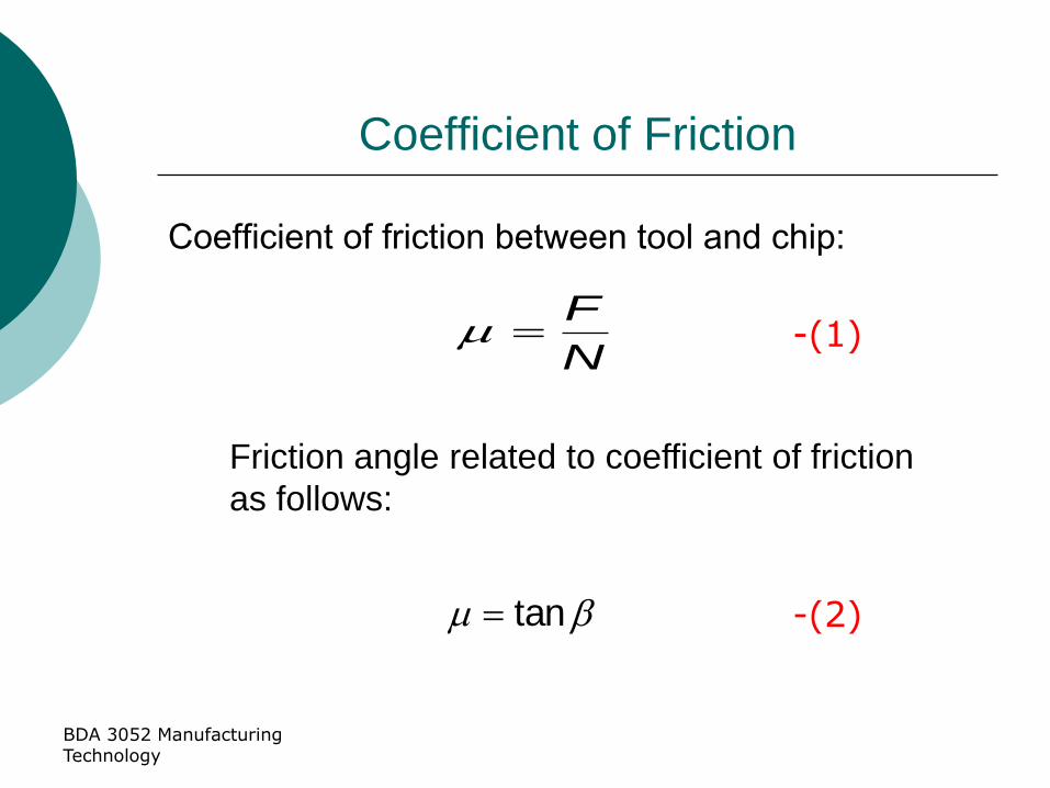
Coefficient of Friction
Coefficient of friction between tool and chip:
Friction angle related to coefficient of friction
as follows:
N
F
tan
-(1)
-(2)

BDA 3052 Manufacturing Technology
Shear Stress
Shear stress acting along the shear plane:
sin
wtA o
s
where As = area of the shear plane
Shear stress = shear strength of work material during
cutting
s
s
A
FS -(3)
-(4)

BDA 3052 Manufacturing Technology
F, N, Fs, and Fn cannot be directly measured
Forces acting on the tool that can be measured:
Cutting force Fc and Thrust force Ft
Forces in metal
cutting: (b) forces
acting on the tool that
can be measured
Cutting Force and Thrust Force

BDA 3052 Manufacturing Technology
Merchant’s circle diagram

BDA 3052 Manufacturing Technology
Merchant’s circle diagram

BDA 3052 Manufacturing Technology
Forces in Metal Cutting
Equations can be derived to relate the forces that
cannot be measured to the forces that can be
measured:
F = Fc sin + Ft cos (5)
N = Fc cos - Ft sin (6)
Fs = Fc cos - Ft sin (7)
Fn = Fc sin + Ft cos (8)
Based on th ese calculated force, shear stress
and coefficient of friction can be determined

BDA 3052 Manufacturing Technology
Example of Problem 3
Cutting force = 1559 N
Thrust force = 1271 N
Width of cutting = 3 mm
Rake angle = 10
Shear plane angle = 25.4
Original Thickness = 0.5 mm
Determine the shear strength of the work
material.
shear stress, S / shear strength, = 247 N/mm2

BDA 3052 Manufacturing Technology
Forces in Metal Cutting
From equation 3, the force diagram (Merchant ‘s Circle
Diagram), can be used to derived the following
equations:
)cos(
)cos(
)cos(sin
)cos(
so
c
FwStF
)cos(
)sin(
)cos(sin
)sin(
so
t
FwStF

BDA 3052 Manufacturing Technology
The Merchant Equation
From equation 3, 4 and 7, Merchant Equation for shear
stress can be expressed as,
)sin/(
sincos
o
tc
t
FF

BDA 3052 Manufacturing Technology
The Merchant Equation
Of all the possible angles at which shear
deformation can occur, the work material will
select a shear plane angle that minimizes
energy, given by
Derived by Eugene Merchant
Based on orthogonal cutting, but validity extends
to 3-D machining
2245
BDA 3052 Manufacturing Technology
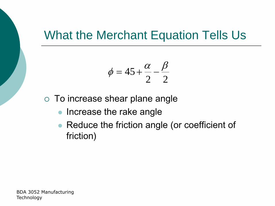
What the Merchant Equation Tells Us
To increase shear plane angle
Increase the rake angle
Reduce the friction angle (or coefficient of
friction)
2245

BDA 3052 Manufacturing Technology
Power and Energy Relationships
A machining operation requires power
The power to perform machining can be
computed from:
Pc = Fc
where Pc = cutting power (Nm/s); Fc = cutting force
(N); and = cutting speed (m/min)

BDA 3052 Manufacturing Technology
Power and Energy Relationships
In U.S. customary units, power is traditional
expressed as horsepower
HPc = Fc/33,000
where HPc = cutting horsepower, hp

BDA 3052 Manufacturing Technology
Power and Energy Relationships
Gross power to operate the machine tool Pg or
HPg is given by
or
where E = mechanical efficiency of machine tool
Typical E for machine tools 90%
E
PP c
g E
HPHP c
g

BDA 3052 Manufacturing Technology
Unit Power in Machining
Useful to convert power into power per unit
volume rate of metal cut
Called unit power, Pu or unit horsepower, HPu
or
where MRR = material removal rate (mm3/s)
MRR
PP c
U MRR
HPHP c
u
BDA 3052 Manufacturing Technology
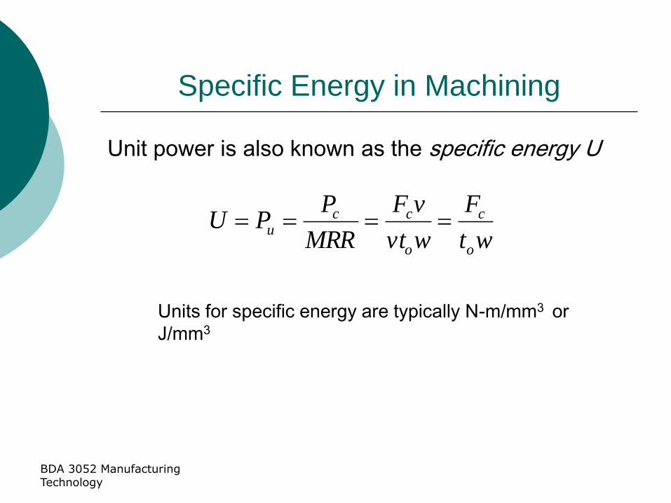
Specific Energy in Machining
Unit power is also known as the specific energy U
Units for specific energy are typically N-m/mm3 or
J/mm3
wt
F
wvt
vF
MRR
PPU
o
c
o
ccu

BDA 3052 Manufacturing Technology
Cutting Temperature
Approximately 98% of the energy in machining is
converted into heat
This can cause temperatures to be very high at
the tool-chip
The remaining energy (about 2%) is retained as
elastic energy in the chip
BDA 3052 Manufacturing Technology
Cutting Temperature is Important
High cutting temperatures
1. Reduce tool life
2. Produce hot chips that pose safety hazards to
the machine operator
3. Can cause inaccuracies in part dimensions due
to thermal expansion of work material

BDA 3052 Manufacturing Technology
Cutting Temperature
Analytical method derived by Nathan Cook
from dimensional analysis using
experimental data for various work materials
where T = temperature rise at tool-chip interface; U =
specific energy; v = cutting speed; to = chip thickness
before cut; C = volumetric specific heat of work
material; K = thermal diffusivity of work material
333040
..
K
vt
C
UT o

BDA 3052 Manufacturing Technology
Example Problem 6
Cutting speed = 100 m/min
Chip original thickness = 0.5 mm
Thermal diffusivity = 50 mm2/s
Specific Energy = 1.038
Volumetric specific heat work material = 3 x10⁻³ J/mm3
Find the mean temperature rise at the tool-chip
Interface.

BDA 3052 Manufacturing Technology
Cutting Temperature
Experimental methods can be used to measure temperatures in machining
Most frequently used technique is the tool-chip thermocouple
Using this method, Ken Trigger determined the speed-temperature relationship to be of the form:
T = K vm
where T = measured tool-chip interface temperature, and v = cutting speed
K and m depend on the cutting conditions and work material

Machining
A material removal process in which a sharp cutting tool is used to mechanically cut away material so that the desired part geometry remains
Most common application: to shape metal parts
Most versatile of all manufacturing processes in its capability to produce a diversity of part geometries and geometric features with high precision and accuracy
Casting can also produce a variety of shapes, but it lacks the precision and accuracy of machining

Rotational - cylindrical or disk-like shape
Nonrotational (also called prismatic) -
block-like or plate-like
Machined parts are classified as: (a) rotational, or (b) nonrotational,
shown here by block and flat parts.
Classification of Machined Parts

Machining Operations and Part
Geometry
Each machining operation produces a
characteristic part geometry due to two
factors:
1. Relative motions between tool and workpart
• Generating – part geometry determined
by feed trajectory of cutting tool
2. Shape of the cutting tool
• Forming – part geometry is created by
the shape of the cutting tool

Figure 22.2 Generating shape: (a) straight turning, (b) taper turning, (c)
contour turning, (d) plain milling, (e) profile milling.
Generating Shape

Forming to create shape: (a) form turning, (b) drilling, and (c) broaching.
Forming to Create Shape

Combination of forming and generating to create shape: (a) thread
cutting on a lathe, and (b) slot milling.
Forming and Generating

Turning
Single point cutting tool removes material from a
rotating workpiece to generate a cylinder
Performed on a machine tool called a lathe
Variations of turning performed on a lathe:
Facing
Contour turning
Chamfering
Cutoff
Threading

Turning operation.
Turning
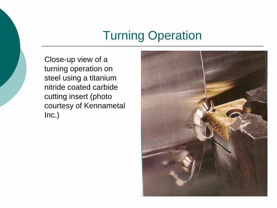
Turning Operation
Close-up view of a
turning operation on
steel using a titanium
nitride coated carbide
cutting insert (photo
courtesy of Kennametal
Inc.)

Tool is fed
radially inward
Facing

Instead of feeding tool
parallel to axis of
rotation, tool follows a
contour that is other
than straight, thus
creating a contoured
shape
Contour Turning

Cutting edge cuts an angle on the corner of
the cylinder, forming a "chamfer"
Chamfering

Tool is fed radially into rotating work at some
location to cut off end of part
Cutoff

Tool is fed radially into rotating work at some
location to cut off end of part
Cutoff

Pointed form tool is fed linearly across surface of rotating workpart parallel to axis of rotation at a large feed rate, thus creating threads
Threading

The rotational speed in turning related to the desired cutting
speed at the surface of the cylindrical workpiece by the
equation:
N = rotational speed, rev/min; = cutting speed, m/min,
And Do = original diameter of the part, m.
Cutting Conditions in Turning - 1
DN

The change in diameter is determined by the depth of cut,
d:
Do – Df = 2d
Do = original diameter, mm; Df = final diameter, mm
d = depth of cut
Cutting Conditions in Turning - 2

The feed in turning is generally expressed in mm/rev. This
feed can be converted to linear travel rate in mm/min by the
formula:
fr = Nf
fr = feed rate, mm/min; f = feed mm/rev
Cutting Conditions in Turning - 3

The time to machine from one end of a cylindrical workpart
to the other is given by:
Tm = L/fr
Tm = time of actual machining, minutes; and L = length of
the cylindrical workpart, mm
Cutting Conditions in Turning - 4

The volumetric rate of material removal rate can be most
conveniently determined by the following equation:
MRR = vfd
MRR = material removal rate, mm3/min, f = feed, mm
Cutting Conditions in Turning - 5

A cylindrical workpart 200 mm in diameter
and 700 mm long is to be turned in an
engine lathe. Cutting conditions are as
follows: cutting speed is 2.30 m/s, feed is
0.32 mm/rev, and depth of cut is 1.80
mm.
Determine (a) cutting time, and (b)
metal removal rate.
Cutting Conditions in Turning
Problem 1

A work materials are to be turned to final size of
175 mm length having diameter of 60 mm.
Total length of the work material is 300 mm. A
single point tool having a certain degree of rake
angle is used. The work material rotates at 1400
RPM. The feed is 0.35 mm / revolution.
Final size of the work material is 51 mm.
Calculate:
1. Cutting velocity,
2. Time taken to machine to the length of 55 mm,
3. Total Material removal rate to get 51 mm diameter.
Cutting Conditions in Turning
Problem 2

Milling
Machining operation in which work is fed past a
rotating tool with multiple cutting edges
Axis of tool rotation is perpendicular to feed
Creates a planar surface
Other geometries possible either by cutter
path or shape
Other factors and terms:
Interrupted cutting operation
Cutting tool called a milling cutter, cutting
edges called "teeth"
Machine tool called a milling machine

Peripheral Milling vs. Face Milling
Peripheral milling
Cutter axis parallel to surface being machined
Cutting edges on outside periphery of cutter
Face milling
Cutter axis perpendicular to surface being
milled
Cutting edges on both the end and outside
periphery of the cutter

METHODS OF MILLING-1
1) Up milling is also referred to as conventional milling. The direction of the cutter rotation opposes the feed motion. For example, if the cutter rotates clockwise , the workpiece is fed to the right in up milling.

METHODS OF MILLING-2
2) Down milling is also referred to as climb milling. The direction of cutter rotation is same as the feed motion. For example, if the cutter rotates counterclockwise , the workpiece is fed to the right in down milling

Basic form of peripheral milling in which the
cutter width extends beyond the workpiece
on both sides
Slab Milling

Width of cutter is less than workpiece width, creating a slot in the work
Slotting

Cutter overhangs work
on both sides
Conventional Face Milling
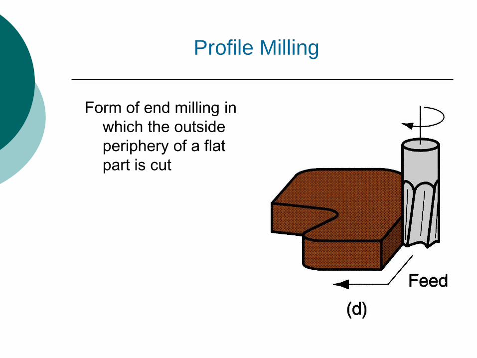
Form of end milling in
which the outside
periphery of a flat
part is cut
Profile Milling

Another form of end milling used to mill shallow pockets into flat parts
Pocket Milling

Ball-nose cutter fed back and forth across work along a curvilinear path at close intervals to create a three dimensional surface form
Surface Contouring

Cutter diameter is
less than work
width, so a slot is
cut into part
End Milling

Machining Centers
Highly automated machine tool can perform
multiple machining operations under CNC
control in one setup with minimal human
attention
Typical operations are milling and drilling
Three, four, or five axes
Other features:
Automatic tool-changing
Pallet shuttles
Automatic workpart positioning

High speed face
milling using
indexable inserts
(photo courtesy
of Kennametal
Inc.).
Milling Operation

The cutting speed is determined at the
outside diameter of a milling cutter.
N = rotational speed, rev/min; = cutting speed,
m/min,
And Do = outside diameter of a milling cutter,mm.
Cutting Conditions in Milling - 1
DN

The feed, f in milling is usually given as a feed per cutter
tooth; called the chip load, it represents the size of the chip
formed by each cutting edge.
fr = Nnt f
fr = feed rate, mm/min; N = spindle speed, rev/min; nt =
number of teeth on the cutter; f = chip load in mm/tooth
Cutting Conditions in Milling - 2

The material removal rate,
MRR = wdfr
w = width; d = depth of cut; fr = feed rate, mm/min;
Cutting Conditions in Milling - 3
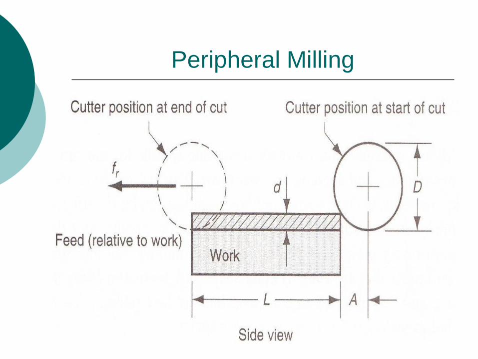
Peripheral Milling

Approach distance A, to reach full cutter depth given by:
d = depth of cut, mm, and D = diameter of the milling cutter,
mm
Cutting Conditions in Milling - 4
)( dDdA

The time to mill the workiece Tm is
therefore;
Cutting Conditions in Milling - 5
r
mf
ALT

Face Milling – cutter is centered

Where A and O are each to half the cutter
diameter;
A = O = D/2
D= cutter diameter, mm
Cutting Conditions in Milling - 6
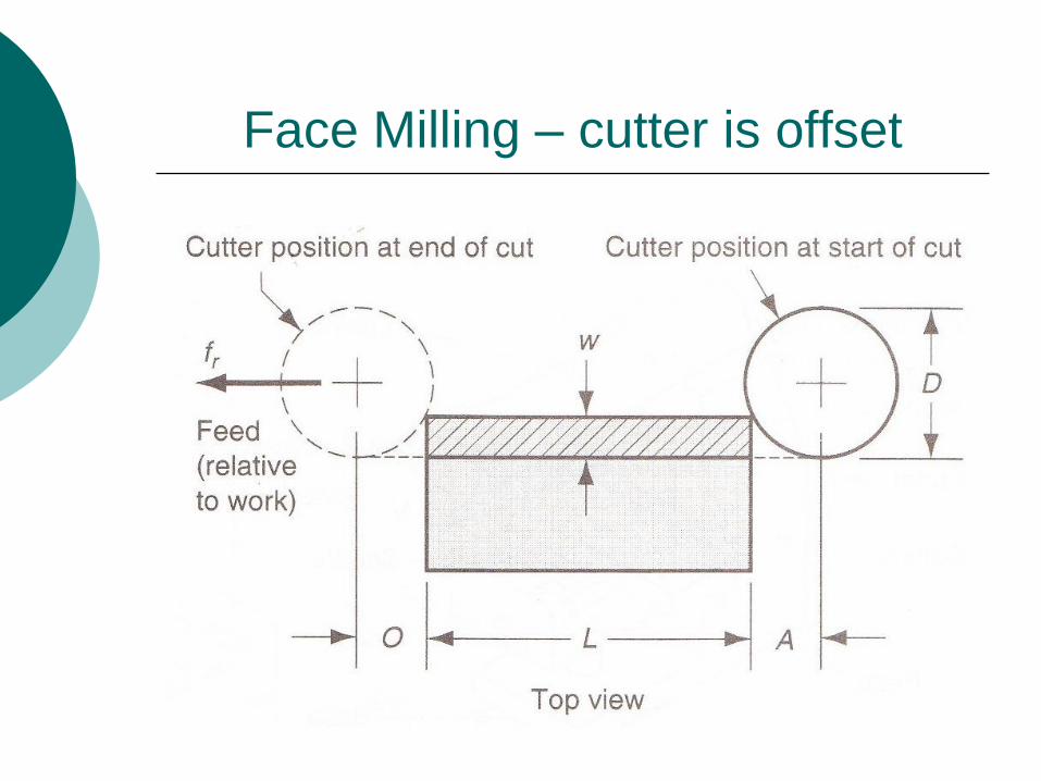
Face Milling – cutter is offset

Where A and O are each to half the cutter
diameter;
w= width of the cut, mm
Cutting Conditions in Milling - 7
)( wDwOA

The time to mill the workiece in face
milling,Tm is therefore;
Cutting Conditions in Milling - 8
r
mf
ALT
2
A peripheral milling operation is performed
on the top surface of a rectangular
workpart which is 400 mm long by 60 mm
wide. The milling cutter, which is 80 mm in
diameter and has five teeth, overhangs the
width of the part on both sides. The cutting
speed is 70 m/min, the chip load is 0.25
mm/tooth, and the depth of cut is 5.0 mm.
Determine (a) the time to make one pass
across the surface, and (b) the maximum
material removal rate during the cut.
Cutting Conditions in Milling
Problem 1

A face milling operation is performed to finish
the top surface of a steel rectangular work
piece 350 mm long by 55 mm wide. The milling
cutter has four teeth (cemented carbide inserts)
and a 85 mm diameter. Cutting conditions are:
v = 600 m/min, f = 0.35 mm / tooth, and d =
3.5 mm.
Determine:
a) the time to make one pass across the surface.
b) the metal removal rate during the cut.
Cutting Conditions in Milling
Problem 2

Creates a round
hole in a workpart
Compare to boring
which can only
enlarge an existing
hole
Cutting tool called
a drill or drill bit
Machine tool: drill press
Drilling

Through-holes - drill exits opposite side of work
Blind-holes – does not exit work opposite side
Two hole types: (a) through-hole, and (b) blind hole.
Through Holes vs. Blind Holes

Used to slightly
enlarge a hole,
provide better
tolerance on
diameter, and
improve surface
finish
Reaming

Used to provide
internal screw
threads on an
existing hole
Tool called a tap
Tapping

Provides a stepped
hole, in which a
larger diameter
follows smaller
diameter partially
into the hole
Counterboring

Letting N represent the spindle rev/min,
= cutting speed, m/min; D = the drill
diameter,mm.
Cutting Conditions in Drilling - 1
DN

Feed can be converted to feed rate using the the same
equation as for turning:
fr = Nf
fr = feed rate, mm/min; N = spindle speed, rev/min; f = feed
in drilling, mm/rev
Cutting Conditions in Drilling - 2

The time to drill through holes;
Tm= machining time, min; t = work thickness,
mm; fr = feed rate, mm/min
Cutting Conditions in Drilling - 3
r
mf
AtT

The allowance is given by;
A = approach allowance, mm; = drill point angle
Cutting Conditions in Drilling - 4
290tan5.0
DA

The time to drill blind holes;
Tm= machining time, min; d = hole depth,
mm; fr = feed rate, mm/min
Cutting Conditions in Drilling - 5
r
mf
dT

A drilling operation is to be performed with a
12.7 mm diameter twist drill in a steel
workpart. The hole is a blind hole at a depth of
60 mm and the point angle is 118. The cutting
speed is 25 m/min and the feed is 0.30
mm/rev.
Determine
(a) the cutting time to complete the drilling
operation, and
(b) metal removal rate during the operation, after the drill bit reaches full diameter.
Cutting Conditions in Drilling
Problem 1

CUTTING TOOL TECHNOLOGY
1. Tool Life
2. Tool Materials
3. Tool Geometry
4. Cutting Fluids

Cutting Tool Technology
Two principal aspects:
1. Tool material
2. Tool geometry

Three Modes of Tool Failure
1. Fracture failure
Cutting force becomes excessive and/or
dynamic, leading to brittle fracture
2. Temperature failure
Cutting temperature is too high for the tool
material
3. Gradual wear
Gradual wearing of the cutting tool

Preferred Mode: Gradual Wear
Fracture and temperature failures are premature
failures
Gradual wear is preferred because it leads to the
longest possible use of the tool
Gradual wear occurs at two locations on a tool:
Crater wear – occurs on top rake face
Flank wear – occurs on flank (side of tool)

Figure 23.1 Diagram of worn cutting tool, showing the principal
locations and types of wear that occur.
Tool Wear

Figure 23.2 Crater wear,
(above), and flank wear (right) on
a cemented carbide tool, as seen
through a toolmaker's
microscope (photos by K. C.
Keefe, Manufacturing Technology
Lab, Lehigh University).

FLANK WEAR and BUE

CRATER WEAR

BUILT UP EDE

Taylor Tool Life Equation
Relationship is credited to F. W. Taylor
CvT n
where v = cutting speed; T = tool life; and n and Care parameters that depend on feed, depth of cut,
work material, tooling material, and the tool life
criterion used
n is the slope of the plot
C is the intercept on the speed axis at one minute
tool life

Tool Life Criteria in Production
1. Complete failure of cutting edge
2. Visual inspection of flank wear (or crater wear) by the machine operator
3. Fingernail test across cutting edge
4. Changes in sound emitted from operation
5. Chips become ribbon-like, stringy, and difficult to dispose of
6. Degradation of surface finish
7. Increased power
8. Workpiece count
9. Cumulative cutting time

Tool Materials
Tool failure modes identify the important
properties that a tool material should possess:
Toughness - to avoid fracture failure
Hot hardness - ability to retain hardness at
high temperatures
Wear resistance - hardness is the most
important property to resist abrasive wear