topic 3 metal casting 160214
TRANSCRIPT
FUNDAMENTALS OF METAL
CASTING
1. Why metal casting is so important
-casting in manufacturing process
1. Solidification of molten metal
-heating the metal, pouring, analysis, fluidity
1. Solidification and Cooling
-solidification of metals and time, shrinkage,
directional solidifications

Why metal casting important?
Capability of metal casting
Can produce internal cavities or hollow section
Very large parts and complex part can be
produced in one piece
Can utilize materials that are difficult or
uneconomical to process
Can create both external and internal shapes
Some casting methods are suited to mass
production
Some casting processes are net shape; others
are near net shape
Disadvantages of Casting
Different disadvantages for different casting
processes:
Limitations on mechanical properties
Poor dimensional accuracy and surface finish
for some processes; e.g., sand casting
Safety hazards to workers due to hot molten
metals
Environmental problems

Parts Made by Casting
Big parts
Engine blocks and heads for automotive
vehicles, wood burning stoves, machine
frames, railway wheels, pipes, church bells, big
statues, pump housings
Small parts
Dental crowns, jewelry, small statues, frying
pans
All varieties of metals can be cast - ferrous and
non-ferrous.

Cooling Curve for a Pure Metal
A pure metal solidifies at a constant temperature
equal to its freezing point (same as melting
point)
Figure 10.4 Cooling curve for a pure metal during casting.

Solidification of Alloys
Most alloys freeze over a temperature range
rather than at a single temperature
Figure 10.6 (a) Phase diagram for a copper-nickel alloy
system and (b) associated cooling curve for a
50%Ni-50%Cu composition during casting.

Figure 10.7 Characteristic grain structure in solidification
Solidification of Alloys

Solidification Time
Solidification takes time
Total solidification time TTS = time required for
casting to solidify after pouring
TTS depends on size and shape of casting by
relationship known as Chvorinov's Rule
where TST = total solidification time; V = volume of the
casting; A = surface area of casting; n = exponent with
typical value = 2; and Cm is mold constant.
n
mTSA
VCT

Mold Constant in Chvorinov's Rule
Mold constant Cm depends on:
Mold material
Thermal properties of casting metal
Pouring temperature relative to melting point
Value of Cm for a given casting operation can be
based on experimental data from previous
operations carried out using same mold material,
metal, and pouring temperature, even though the
shape of the part may be quite different

What Chvorinov's Rule Tells Us
A casting with a higher volume-to-surface area
ratio cools and solidifies more slowly than one
with a lower ratio
To feed molten metal to main cavity, TST for
riser must greater than TST for main casting
Since mold constants of riser and casting will be
equal, design the riser to have a larger
volume-to-area ratio so that the main casting
solidifies first
This minimizes the effects of shrinkage

Casting
Process in which molten metal flows by gravity or
other force into a mold where it solidifies in the
shape of the mold cavity
The term casting also applies to the part made in
the process
Steps in casting is simple:
1. Melt the metal
2. Pour it into a mold
3. Allow to freeze or solidify

Solidification Processes
Starting work material is either a liquid or is in a
highly plastic condition, and a part is created
through solidification of the material
Solidification processes can be classified
according to engineering materials:
Metals
Ceramics, specifically glasses
Polymers and polymer matrix composites
(PMCs)

Heating the Metal
Heating furnaces are used to heat the
metal to molten temperature sufficient for
casting
The heat required is the sum of:
1. Heat to raise temperature to melting point
2. Heat of fusion to convert from solid to liquid
3. Heat to raise molten metal to desired
temperature for pouring

Pouring the Molten Metal
For this step to be successful, metal must flow
into all regions of the mold, most importantly the
main cavity, before solidifying
Factors that determine success
Pouring temperature
Pouring rate
Turbulence

Metals for Casting
Most commercial castings are made of alloys
rather than pure metals
Alloys are generally easier to cast, and
properties of product are better
Casting alloys can be classified as:
Ferrous
Nonferrous
Ferrous Casting Alloys: Cast Iron
Most important of all casting alloys
Tonnage of cast iron castings is several times that
of all other metals combined
Several types: (1) gray cast iron, (2) nodular iron,
(3) white cast iron, (4) malleable iron, and (5) alloy
cast irons
Typical pouring temperatures 1400C (2500F),
depending on composition

Ferrous Casting Alloys: Steel
The mechanical properties of steel make it an
attractive engineering material
The capability to create complex geometries
makes casting an attractive shaping process
Difficulties when casting steel:
Pouring temperature of steel is higher than for
most other casting metals 1650C (3000F)
At such temperatures, steel readily oxidizes, so
molten metal must be isolated from air
Molten steel has relatively poor fluidity

Nonferrous Casting Alloys: Aluminum
Generally considered to be very castable
Pouring temperatures low due to low melting
temperature of aluminum
Tm = 660C (1220F)
Properties:
Light weight
Range of strength properties by heat treatment
Easy to machine
Nonferrous Casting Alloys: Copper
Alloys
Includes bronze, brass, and aluminum bronze
Properties:
Corrosion resistance
Attractive appearance
Good bearing qualities
Limitation: high cost of copper
Applications: pipe fittings, marine propeller
blades, pump components, ornamental jewelry

Nonferrous Casting Alloys: Zinc Alloys
Highly castable, commonly used in die casting
Low melting point – melting point of zinc Tm =
419C (786F)
Good fluidity for ease of casting
Properties:
Low creep strength, so castings cannot be
subjected to prolonged high stresses

Solidification of Metals
Transformation of molten metal back into solid
state
Solidification differs depending on whether the
metal is
A pure element or
An alloy

Solidification of Pure Metals
Due to chilling action of mold wall, a thin skin of
solid metal is formed at the interface immediately
after pouring
Skin thickness increases to form a shell around
the molten metal as solidification progresses
Rate of freezing depends on heat transfer into
mold, as well as thermal properties of the metal

Figure 10.5 Characteristic grain structure in a casting of a pure metal,
showing randomly oriented grains of small size near the mold wall,
and large columnar grains oriented toward the center of the casting.
Solidification of Pure Metals

Shrinkage in Solidification and Cooling
Figure 10.8 Shrinkage of a cylindrical casting during solidification
and cooling: (0) starting level of molten metal immediately after
pouring; (1) reduction in level caused by liquid contraction during
cooling (dimensional reductions are exaggerated for clarity).

Shrinkage in Solidification and Cooling
Figure 10.8 (2) reduction in height and formation of shrinkage
cavity caused by solidification shrinkage; (3) further reduction in
height and diameter due to thermal contraction during cooling of
solid metal (dimensional reductions are exaggerated for clarity).

Solidification Shrinkage
Occurs in nearly all metals because the solid
phase has a higher density than the liquid phase
Thus, solidification causes a reduction in volume
per unit weight of metal
Exception: cast iron with high C content
Graphitization during final stages of freezing
causes expansion that counteracts volumetric
decrease associated with phase change

Shrinkage Allowance
Patternmakers account for solidification shrinkage
and thermal contraction by making mold cavity
oversized
Amount by which mold is made larger relative to
final casting size is called pattern shrinkage allowance
Casting dimensions are expressed linearly, so
allowances are applied accordingly

Directional Solidification
To minimize damaging effects of shrinkage, it is
desirable for regions of the casting most distant
from the liquid metal supply to freeze first and for
solidification to progress from these remote
regions toward the riser(s)
Thus, molten metal is continually available
from risers to prevent shrinkage voids
The term directional solidification describes
this aspect of freezing and methods by which it
is controlled

Achieving Directional Solidification
Desired directional solidification is achieved using
Chvorinov's Rule to design the casting itself, its
orientation in the mold, and the riser system that
feeds it
Locate sections of the casting with lower V/Aratios away from riser, so freezing occurs first in
these regions, and the liquid metal supply for the
rest of the casting remains open
Chills - internal or external heat sinks that cause
rapid freezing in certain regions of the casting

METAL CASTING PROCESSES
1. Sand Casting
-patterns and cores, molds making, casting operation
2. Expendable Mold Casting Processes
-shell, expended polystyrene, investment, plaster and
ceramic
3. Permanent Mold Casting Processes
- permanent mold, variation of permanent mold casting, die
casting
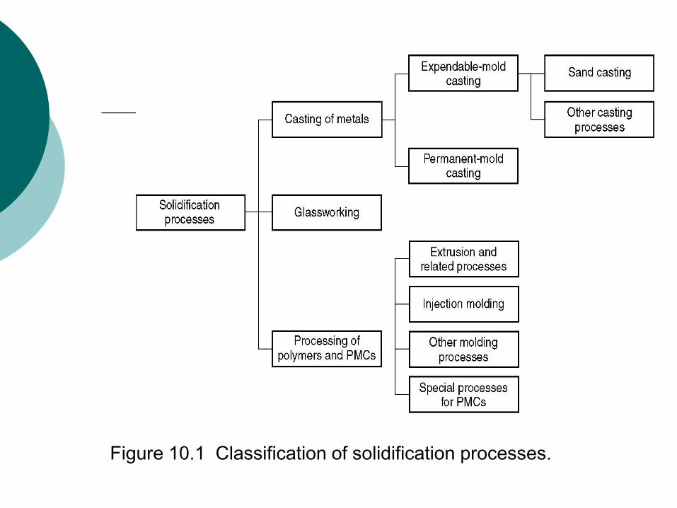
Figure 10.1 Classification of solidification processes.

Two Categories of Casting Processes
1. Expendable mold processes - mold is sacrificed
to remove part
Advantage: more complex shapes possible
Disadvantage: production rates often limited
by time to make mold rather than casting
itself
2. Permanent mold processes - mold is made of
metal and can be used to make many castings
Advantage: higher production rates
Disadvantage: geometries limited by need to
open mold

Open Molds and Closed Molds
Figure 10.2 Two forms of mold: (a) open mold, simply a container
in the shape of the desired part; and (b) closed mold, in which
the mold geometry is more complex and requires a gating
system (passageway) leading into the cavity.

Foundry Sands
Silica (SiO2) or silica mixed with other minerals
Good refractory properties - capacity to endure high temperatures
Small grain size yields better surface finish on the cast part
Large grain size is more permeable, allowing gases to escape during pouring
Irregular grain shapes strengthen molds due to interlocking, compared to round grains
Disadvantage: interlocking tends to reduce permeability

Binders Used with Foundry Sands
Sand is held together by a mixture of water and
bonding clay
Typical mix: 90% sand, 3% water, and 7% clay
Other bonding agents also used in sand molds:
Organic resins (e g , phenolic resins)
Inorganic binders (e g , sodium silicate and
phosphate)
Additives are sometimes combined with the
mixture to increase strength and/or permeability

PROPERTIES OF MOUDLING SAND -1
PERMEABILITY- give way gases to escape, water and steam vapor
COHESIVENESS-Ability of sand particles to stick together
ADHESIVENESS – Sand particles must be capable of sticking to other bodies particularly to molding box. Capable of adhering to another body
PLASTICITY – acquiring pre-determined shape under pressure and to retain it when the pressure is removed.
Collapsibility- Free contraction of mold

PROPERTIES OF MOUDLING SAND - 2
REFRACTORINESS- ability to withstand high heat without breaking down or fusing.
CHEMICAL RESISTIVITY- sand should not chemically react or combine with molten metal so that it can be used again and again.
BINDING PROPERTY- Binder allows sand to flow take up pattern shape
FLOWABILIY- This is similar to plasticity. It is the ability of sand to take up the desired shape. Ability to behave like a fluid. Flowability increases as clay and water content increased.
Porosity- Allow gas to escape

Advantages and Disadvantages
More intricate geometries are possible with
expendable mold processes
Part shapes in permanent mold processes are
limited by the need to open the mold
Permanent mold processes are more economic in
high production operations

Sand Casting Mold
Figure 10.2 (b) Sand casting mold.

Forming the Mold Cavity
Mold cavity is formed by packing sand around a
pattern, which has the shape of the part
When the pattern is removed, the remaining
cavity of the packed sand has desired shape of
cast part
The pattern is usually oversized to allow for
shrinkage of metal during solidification and
cooling
Sand for the mold is moist and contains a binder
to maintain its shape

Use of a Core in the Mold Cavity
The mold cavity provides the external surfaces of
the cast part
In addition, a casting may have internal surfaces,
determined by a core, placed inside the mold
cavity to define the interior geometry of part
In sand casting, cores are generally made of sand

Gating System
Channel through which molten metal flows into
cavity from outside of mold
Consists of a downsprue, through which metal
enters a runner leading to the main cavity
At the top of downsprue, a pouring cup is often
used to minimize splash and turbulence as the
metal flows into downsprue

Riser
Reservoir in the mold which is a source of liquid
metal to compensate for shrinkage of the part
during solidification
The riser must be designed to freeze after the
main casting in order to satisfy its function

Steps in Sand Casting
1. Pour the molten metal into sand mold
2. Allow time for metal to solidify
3. Break up the mold to remove casting
4. Clean and inspect casting
Separate gating and riser system
5. Heat treatment of casting is sometimes required
to improve metallurgical properties

Making the Sand Mold
The cavity in the sand mold is formed by packing
sand around a pattern, then separating the mold
into two halves and removing the pattern
The mold must also contain gating and riser
system
If casting is to have internal surfaces, a core must
be included in mold
A new sand mold must be made for each part
produced

Sand Casting Production Sequence
Figure 11.2 Steps in the production sequence in sand casting.
The steps include not only the casting operation but also
pattern-making and mold-making.

The Pattern
A full-sized model of the part, slightly enlarged to
account for shrinkage and machining allowances
in the casting
Pattern materials:
Wood - common material because it is easy to
work, but it warps
Metal - more expensive to make, but lasts
much longer
Plastic - compromise between wood and metal

Types of Patterns
Figure 11.3 Types of patterns used in sand casting:
(a) solid pattern
(b) split pattern
(c) match-plate pattern
(d) cope and drag pattern

Core
Full-scale model of interior surfaces of part
It is inserted into the mold cavity prior to pouring
The molten metal flows and solidifies between the
mold cavity and the core to form the casting's
external and internal surfaces
May require supports to hold it in position in the
mold cavity during pouring, called chaplets

Core in Mold
Figure 11.4 (a) Core held in place in the mold cavity by
chaplets, (b) possible chaplet design, (c) casting with
internal cavity.

Desirable Mold Properties
Strength - to maintain shape and resist erosion
Permeability - to allow hot air and gases to pass
through voids in sand
Thermal stability - to resist cracking on contact
with molten metal
Collapsibility - ability to give way and allow casting
to shrink without cracking the casting
Reusability - can sand from broken mold be
reused to make other molds.

Types of Sand Mold
Green-sand molds - mixture of sand, clay, and
water;
“Green" means mold contains moisture at time
of pouring
Dry-sand mold - organic binders rather than clay
And mold is baked to improve strength
Skin-dried mold - drying mold cavity surface of a
green-sand mold to a depth of 10 to 25 mm, using
torches or heating lamps

Expendable Mold Processes
Shell Molding
Expanded Polystyrene Process
Investment Casting
Plaster Mold and Ceramic Mold Casting

Shell Molding
Casting process in which the mold is a thin shell of
sand held together by thermosetting resin binder
Figure 11.5 Steps in shell-molding: (1) a match-plate or
cope-and-drag metal pattern is heated and placed over a
box containing sand mixed with thermosetting resin.

Shell Molding
Figure 11.5 Steps in shell-molding: (2) box is inverted so that
sand and resin fall onto the hot pattern, causing a layer of
the mixture to partially cure on the surface to form a hard
shell; (3) box is repositioned so that loose uncured particles
drop away;

Shell Molding
Figure 11.5 Steps in shell-molding: (4) sand shell is heated in
oven for several minutes to complete curing; (5) shell mold
is stripped from the pattern;

Shell Molding
Figure 11.5 Steps in shell-molding: (6) two halves of the shell mold are assembled, supported by sand or metal shot in a box, and pouring is accomplished; (7) the finished casting with sprue removed.

Advantages and Disadvantages
Advantages of shell molding:
Smoother cavity surface permits easier flow of molten
metal and better surface finish
Good dimensional accuracy - machining often not
required
Mold collapsibility minimizes cracks in casting
Can be mechanized for mass production
Special cores may be eliminated
Thin sections can be cast.
Permeability of the shell is high and no gas inclusions
Mechanisms is readily is possible, it is simple process

Disadvantages
Patterns are very expensive
Size is limited. Up to 200 kg may be used.
Highly complicated shape cannot be produced.
More sophisticated equipment is needed for handling.

Expanded Polystyrene Process
Uses a mold of sand packed around a polystyrene
foam pattern which vaporizes when molten metal
is poured into mold
Other names: lost-foam process, lost pattern
process, evaporative-foam process, and full-mold
process
Polystyrene foam pattern includes sprue, risers,
gating system, and internal cores (if needed)
Mold does not have to be opened into cope and
drag sections

Expanded Polystyrene Process
Figure 11.7 Expanded polystyrene casting process: (1) pattern
of polystyrene is coated with refractory compound;

Expanded Polystyrene Process
Figure 11.7 Expanded polystyrene casting process: (2) foam
pattern is placed in mold box, and sand is compacted
around the pattern;

Expanded Polystyrene Process
Figure 11.7 Expanded polystyrene casting process: (3)
molten metal is poured into the portion of the pattern that
forms the pouring cup and sprue. As the metal enters
the mold, the polystyrene foam is vaporized ahead of the
advancing liquid, thus the resulting mold cavity is filled.

Advantages and Disadvantages
Advantages of expanded polystyrene process:
Pattern need not be removed from the mold
Simplifies and speeds mold-making, because
two mold halves are not required as in a
conventional green-sand mold
Disadvantages:
A new pattern is needed for every casting
Economic justification of the process is highly
dependent on cost of producing patterns

Expanded Polystyrene Process
Applications:
Mass production of castings for automobile
engines
Automated and integrated manufacturing
systems are used to
1. Mold the polystyrene foam patterns and
then
2. Feed them to the downstream casting
operation

Investment Casting (Lost Wax Process)
A pattern made of wax is coated with a refractory
material to make mold, after which wax is melted
away prior to pouring molten metal
"Investment" comes from a less familiar definition
of "invest" - "to cover completely," which refers to
coating of refractory material around wax pattern
It is a precision casting process - capable of
producing castings of high accuracy and intricate
detail
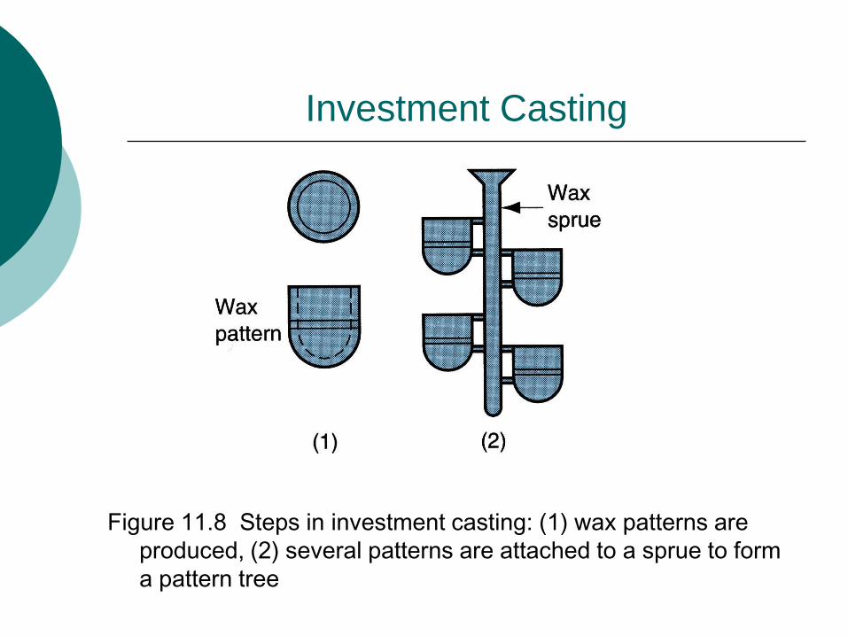
Investment Casting
Figure 11.8 Steps in investment casting: (1) wax patterns are
produced, (2) several patterns are attached to a sprue to form
a pattern tree
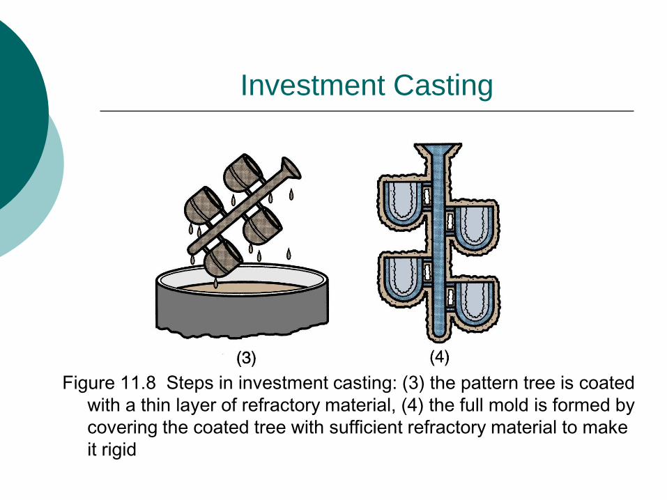
Investment Casting
Figure 11.8 Steps in investment casting: (3) the pattern tree is coated
with a thin layer of refractory material, (4) the full mold is formed by
covering the coated tree with sufficient refractory material to make
it rigid

Investment Casting
Figure 11.8 Steps in investment casting: (5) the mold is held in an
inverted position and heated to melt the wax and permit it to drip out
of the cavity, (6) the mold is preheated to a high temperature, the
molten metal is poured, and it solidifies

Investment Casting
Figure 11.8 Steps in investment casting: (7) the mold is
broken away from the finished casting and the parts are
separated from the sprue

Advantages
Complex shapes which are difficult to produce by any other method are possible
Very fine details and thin sections can be produced
Very close tolerance and better finish can be produced
Very little or no machining required
Since no parting line, dimensions across it would not affect

Disadvantages
Size is limited to weight of the casting
More expensive process because manual labor is required

Plaster Mold Casting*
Similar to sand casting except mold is made of
plaster of Paris (gypsum - CaSO4-2H2O)
In mold-making, plaster and water mixture is
poured over plastic or metal pattern and allowed
to set
Wood patterns not generally used due to
extended contact with water
Plaster mixture readily flows around pattern,
capturing its fine details and good surface finish

Advantages and Disadvantages
Advantages of plaster mold casting:
Good accuracy and surface finish
Capability to make thin cross-sections
Disadvantages:
Mold must be baked to remove moisture,
which can cause problems in casting
Mold strength is lost if over-baked
Plaster molds cannot stand high
temperatures, so limited to lower melting
point alloys

Ceramic Mold Casting*
Similar to plaster mold casting except that mold is
made of refractory ceramic material that can
withstand higher temperatures than plaster
Can be used to cast steels, cast irons, and other
high-temperature alloys
Applications similar to those of plaster mold
casting except for the metals cast
Advantages (good accuracy and finish) also
similar

Permanent Mold Casting Processes
Economic disadvantage of expendable mold
casting: a new mold is required for every casting
In permanent mold casting, the mold is reused
many times
The processes include:
Basic permanent mold casting
Die casting
Centrifugal casting

The Basic Permanent Mold Process
Uses a metal mold constructed of two sections
designed for easy, precise opening and closing
Molds used for casting lower melting point alloys
are commonly made of steel or cast iron
Molds used for casting steel must be made of
refractory material, due to the very high pouring
temperatures

Permanent Mold Casting
Figure 11.10 Steps in permanent mold casting: (1) mold is
preheated and coated

Permanent Mold Casting
Figure 11.10 Steps in permanent mold casting: (2) cores (if used) are inserted and mold is closed, (3) molten metal is poured into the mold, where it solidifies.

Advantages and Limitations
Advantages of permanent mold casting:
Good dimensional control and surface finish
More rapid solidification caused by the cold metal
mold results in a finer grain structure, so castings are
stronger
Economical for large production
Inserts can be readily cast in place
Limitations:
Generally limited to metals of lower melting point
Simpler part geometries compared to sand casting
because of need to open the mold
High cost of mold
Applications of Permanent Mold
Casting
Due to high mold cost, process is best suited to
high volume production and can be automated
accordingly
Typical parts: automotive pistons, pump bodies,
and certain castings for aircraft and missiles
Metals commonly cast: aluminum, magnesium,
copper-base alloys, and cast iron

Die Casting
A permanent mold casting process in which
molten metal is injected into mold cavity under
high pressure
Pressure is maintained during solidification, then
mold is opened and part is removed
Molds in this casting operation are called dies;
hence the name die casting
Use of high pressure to force metal into die cavity
is what distinguishes this from other permanent
mold processes

Die Casting Machines
Designed to hold and accurately close two mold
halves and keep them closed while liquid metal is
forced into cavity
Two main types:
1. Hot-chamber machine
2. Cold-chamber machine
Hot-Chamber Die Casting
Metal is melted in a container, and a piston injects
liquid metal under high pressure into the die
High production rates - 500 parts per hour not
uncommon
Applications limited to low melting-point metals
that do not chemically attack plunger and other
mechanical components
Casting metals: zinc, tin, lead, and magnesium

Hot-Chamber Die Casting
Figure 11.13 Cycle in hot-chamber casting: (1) with die closed
and plunger withdrawn, molten metal flows into the chamber

Hot-Chamber Die Casting
Figure 11.13 Cycle in hot-chamber casting: (2) plunger
forces metal in chamber to flow into die, maintaining
pressure during cooling and solidification.

Cold-Chamber Die Casting Machine
Molten metal is poured into unheated chamber
from external melting container, and a piston
injects metal under high pressure into die cavity
High production but not usually as fast as
hot-chamber machines because of pouring step
Casting metals: aluminum, brass, and
magnesium alloys
Advantages of hot-chamber process favor its use
on low melting-point alloys (zinc, tin, lead)

Cold-Chamber Die Casting
Figure 11.14 Cycle in cold-chamber casting: (1) with die
closed and ram withdrawn, molten metal is poured into
the chamber

Cold-Chamber Die Casting
Figure 11.14 Cycle in cold-chamber casting: (2) ram forces
metal to flow into die, maintaining pressure during cooling
and solidification.

Molds for Die Casting
Usually made of tool steel, mold steel, or
maraging steel
Tungsten and molybdenum (good refractory
qualities) used to die cast steel and cast iron
Ejector pins required to remove part from die
when it opens
Lubricants must be sprayed into cavities to
prevent sticking

Advantages and Limitations
Advantages of die casting:
Economical for large production quantities
Good accuracy and surface finish
Thin sections are possible due to injection of metal
Small thickness can be easily filled
Rapid cooling provides small grain size and good
strength to casting
Longer die life -30,000 pieces
Better mechanical properties
Disadvantages:
Generally limited to metals with low metal points
Part geometry must allow removal from die

Casting Quality
There are numerous opportunities for things to go
wrong in a casting operation, resulting in quality
defects in the product
The defects can be classified as follows:
General defects common to all casting
processes
Defects related to sand casting process

A casting that has solidified before completely filling mold cavity
Figure 11.22 Some common defects in castings: (a) misrun
General Defects: Misrun

Two portions of metal flow together but there is
a lack of fusion due to premature freezing
Figure 11.22 Some common defects in castings: (b) cold shut
General Defects: Cold Shut

Metal splatters during pouring and solid globules form and become entrapped in casting
Figure 11.22 Some common defects in castings: (c) cold shot
General Defects: Cold Shot

Depression in surface or internal void caused by
solidification shrinkage that restricts amount of
molten metal available in last region to freeze
Figure 11.22 Some common defects in castings: (d) shrinkage cavity
General Defects: Shrinkage Cavity

Balloon-shaped gas cavity caused by release of
mold gases during pouring
Figure 11.23 Common defects in sand castings: (a) sand blow
Sand Casting Defects: Sand Blow

Formation of many small gas cavities at or slightly
below surface of casting
Figure 11.23 Common defects in sand castings: (b) pin holes
Sand Casting Defects: Pin Holes

When fluidity of liquid metal is high, it may penetrate
into sand mold or core, causing casting surface to
consist of a mixture of sand grains and metal
Figure 11.23 Common defects in sand castings: (e) penetration
Sand Casting Defects: Penetration

example

A step in cast product at parting line caused by
sidewise relative displacement of cope and drag
Figure 11.23 Common defects in sand castings: (f) mold shift
Sand Casting Defects: Mold Shift

example

Foundry Inspection Methods
Visual inspection to detect obvious defects such as misruns, cold shuts, and severe surface flaws
Dimensional measurements to insure that tolerances have been met
Metallurgical, chemical, physical, and other tests concerned with quality of cast metal