tm 5-697 commissioning of mechanical systems for … · command, control, communications, computer,...
TRANSCRIPT

TM 5-697
HEADQUARTERS, DEPARTMENT OF THE ARMY
26 MAY 2006
TECHNICAL MANUAL
COMMISSIONING OF MECHANICAL SYSTEMS FOR
COMMAND, CONTROL, COMMUNICATIONS, COMPUTER, INTELLIGENCE, SURVEILLANCE, AND RECONNAISSANCE (C4ISR)
FACILITIES
APPROVED FOR PUBLIC RELEASE: DISTRIBUTION IS UNLIMITED

TM 5-697
REPRODUCTION AUTHORIZATION/RESTRICTIONS
This manual has been prepared by or for the Government and, except to the extent indicated below, is public property and not subject to copyright. Reprint or republication of this manual should include a credit substantially as follows: “Department of the Army, TM 5-697, Commissioning of Mechanical Systems for Command, Control, Communications, Computer, Intelligence, Surveillance, and Reconnaissance (C4ISR) Facilities, 26 May 2006.”
TM 5-697 CONTENTS
THIS MANUAL SUPERSEDES TM 5-697 DATED 6 DECEMBER 2002 i
Technical Manual HEADQUARTERS DEPARTMENT OF THE ARMY No. 5-697 Washington, DC, 26 May 2006
APPROVED FOR PUBLIC RELEASE; DISTRIBUTION IS UNLIMITED
COMMISSIONING OF MECHANICAL SYSTEMS FOR COMMAND, CONTROL, COMMUNICATIONS, COMPUTER, INTELLIGENCE, SURVEILLANCE, AND RECONNAISSANCE (C4ISR) FACILITIES
CONTENTS Paragraph Page CHAPTER 1 INTRODUCTION Purpose 1-1 1-1 Scope 1-2 1-1 References
Objectives 1-3 1-4
1-1 1-1
General system testing requirements Component testing System commissioning testing Cost of Commissioning Examples of commissioning
1-5 1-6 1-7 1-8 1-9
1-2 1-2 1-2 1-3 1-3
CHAPTER 2 THE NEED FOR COMMISSIONING General background 2-1 2-1 The importance of commissioning 2-2 2-1 The economics of commissioning 2-3 2-2 CHAPTER 3 THE COMMISSIONING PROCESS General 3-1 3-1 Commissioning applicability to project phases 3-2 3-2 CHAPTER 4 HEATING, VENTILATING, AND AIR-CONDITIONING (HVAC)
EQUIPMENT AND CONTROLS
Description of HVAC systems 4-1 4-1 Operation of HVAC systems 4-2 4-2 General HVAC equipment description and operation 4-3 4-4 Pre-functional test plan and functional performance test plan for
HVAC systems 4-4 4-11
Possible failures and corrective measures for HVAC systems 4-5 4-11 CHAPTER 5 GENERATORS AND ANCILLARY EQUIPMENT Description of generator ancillary equipment, diesel fuel, and lube oil
systems 5-1 5-1
Operation of diesel fuel system and lube oil systems 5-2 5-2 Pre-functional test plan and functional performance test plan for diesel
fuel and lube oil systems 5-3
5-3

TM 5-697 CONTENTS
ii
Paragraph Page Possible failures and corrective measures for diesel fuel and lube oil
systems 5-4 5-4
CHAPTER 6 AIR COMPRESSORS AND PNEUMATIC CONTROL SYSTEMS Description of compressed air and pneumatic control systems 6-1 6-1 Operation of compressed air systems 6-2 6-2 General compressed air equipment description and operation 6-3 6-2 Pre-functional test plan and functional performance test plan for
compressed air systems 6-4 6-4
Possible failures and corrective measures for compressed air systems 6-5 6-5 CHAPTER 7 FIRE FIGHTING AND SUPPRESSION SYSTEMS Description of wet pipe sprinkler systems and fire detection systems 7-1 7-1 Operation of wet pipe sprinkler systems and fire detection systems 7-2 7-2 General fire fighting and suppression system equipment description
and operation 7-3 7-3
Pre-functional test plan and functional performance test plan for wet pipe sprinkler systems and fire detection systems
7-4 7-4
Possible failures and corrective measures for wet pipe sprinkler system and fire detection system
7-5 7-7
CHAPTER 8 LIFTING AND MOVING DEVICES SUCH AS CRANES AND
ELEVATORS
Description of lifting and moving devices 8-1 8-1 Operation of lifting and moving devices 8-2 8-1 Pre-functional test plan and functional performance test plan for lifting
and moving devices 8-3 8-2
Possible failures and corrective measures for lifting and moving devices
8-4 8-6
CHAPTER 9 HIGH ALTITUDE ELECTROMAGNETIC PULSE (HEMP)
EQUIPMENT AND CONTROLS
Description of HEMP protection for mechanical systems 9-1 9-1 Operation of HEMP protection for mechanical systems 9-2 9-2 Pre-functional test plan and functional performance test plan for
HEMP protection of mechanical systems 9-3 9-2
Possible failures and corrective measures for HEMP protection of mechanical systems
9-4 9-2
CHAPTER 10 WATER AND SEWAGE TREATMENT SYSTEMS Description of water and sewage treatment systems 10-1 10-1 Operation of water and sewage treatment systems 10-2 10-4 General water and sewage treatment equipment description and
operation 10-3 10-6
Pre-functional test plan and functional performance test plan for water and sewage treatment systems
10-4 10-9
Possible failures and corrective measures for water and sewage treatment systems
10-5 10-10
APPENDIX A REFERENCES A-1

TM 5-697 CONTENTS
THIS MANUAL SUPERSEDES TM 5-697 DATED 6 DECEMBER 2002 iii
Paragraph Page GLOSSARY G-1
List of Tables
Table Title Page Table 1-1 Table 4-1
Costs of constructon, new construction Possible failures and corrective actions of HVAC system
1-3 4-16
Table 5-1 Possible failures and corrective actions for diesel fuel and lube oil systems 5-7 Table 6-1 Possible failures and correction actions for compressed air system 6-7 Table 7-1 Possible failures and correction actions for wet pipe sprinkler system and fire
detection system 7-7
Table 8-1 Possible failures and corrective actions for lifting and moving devices 8-6 Table 9-1 Possible failures and corrective actions for HEMP protection of mechanical
systems 9-4
Table 10-1 Possible failures and corrective actions for water supply, water treatment, and sewage treatment systems
10-13
List of Figures Figure Title Page Figure 4-1 Schematic of a typical HVAC system 4-2 Figure 4-2 Typical HVAC control loop 4-3 Figure 4-3 Example: DA Form 7477-R 4-12 Figure 4-4 Example: DA Form 7478-R 4-13 Figure 4-5 Example: DA Form 7479-R 4-14 Figure 5-1 Schematic of a typical diesel fuel system 5-1 Figure 5-2 Schematic of a typical lube oil system 5-2 Figure 5-3 Example: DA Form 7480-R 5-5 Figure 5-4 Example: DA Form 7481-R 5-6 Figure 6-1 Schematic of a typical compressed air system 6-1 Figure 6-2 Example: DA Form 7482-R 6-6 Figure 7-1 Typical wet pipe sprinkler system 7-1 Figure 7-2 Example: DA Form 7483-R 7-6 Figure 8-1 Example: DA Form 7484-R 8-4 Figure 8-2 Example: DA Form 7485-R 8-5 Figure 9-1 Example: DA Form 7486-R 9-3 Figure 10-1 Schematic of a typical potable and process water system 10-1 Figure 10-2 Schematic of a process water treatment system 10-2 Figure 10-3 A cross section of a septic tank 10-3 Figure 10-4 Sewage trickling filter process 10-3 Figure 10-5 Example: DA Form 7487-R 10-11 Figure 10-6 Example: DA Form 7488-R 10-12

TM 5-697
1-1
CHAPTER 1
INTRODUCTION ____________________________________________________________ 1-1. Purpose This manual establishes minimum requirements for the process of commissioning mechanical systems supporting major fixed command, control, communications, computers, intelligence, surveillance, and reconnaissance (C4ISR) facilities. The purpose of this manual is to provide facility managers the information necessary to plan for and implement commissioning of mechanical systems. The commissioning process (sometimes referred to as “acceptance testing”) includes achieving, verifying, testing, accepting, and documenting that the performance of mechanical systems meets design intent and the owner and occupant needs. Ideally, the process begins at the program phase and lasts at least one year after project-closeout. The commissioning process involves the participation of all parties in the building delivery cycle, including, but not limited to representatives of the owner, designer and appropriate contractors. At project closeout, systems needed for immediate operation of the facility have been tested and are considered acceptable. Upon achieving final acceptance at the conclusion of the post acceptance period, the last step of the commissioning process, the owner and/or his operating and maintenance (O & M) contractor take over full ownership and responsibility of the mechanical systems.
1-2. Scope
This manual shall be used for the process of commissioning mechanical systems in C4ISR facilities. The commissioning process applies to all phases of a facility’s life-cycle including program, design, construction, acceptance, post-acceptance phases and training of O & M staff, and can be applied throughout the life of the building. This technical manual applies to assessment/testing of new construction (i.e., commissioning), reassessment/retesting of existing facilities, or facilities modified or fitted with new equipment (i.e., re-commissioning), and also to assessment/testing of operating facilities which were not commissioned when new (i.e., retro-commissioning). The requirements of this manual are predominantly for testing systems. It is assumed that detailed/comprehensive individual testing of equipment has been completed. The mechanical systems included are for specifically designated fixed ground-based facilities in a threat-hardened C4ISR network.
1-3. References Required and related publications and prescribed forms are listed in appendix A. 1-4. Objectives
Survivable C4ISR capabilities are essential for a credible military deterrent. This manual supports threat-survivability objectives by providing standardized commissioning and re-commissioning of mechanical systems for support of fixed ground-based facilities in a threat-hardened C4ISR network. These uniform requirements ensure balanced threat hardening for all critical facilities in the network. 1-5. General system testing requirements

TM 5-697
1-2
The purpose of mechanical systems commissioning is to increase the reliability of mechanical power systems after installation by identifying problems and providing a set of baseline values for comparison with subsequent routine tests. A procedure should be developed to include a planned approach (road map) of what should be done in order to verify the proper system installation. This procedure is the commissioning plan. Specific areas addressed in a commissioning plan include the verification of the installation of all equipment/components, interface connections between equipment and individual systems, and interconnection drawings. The development of this test plan specific to each system and/or component is key to the usefulness of any maintenance program. The plan consists of the schedule of when acceptance and routine tests should be performed, test forms to be used to record the outcome of the tests which are retained for comparison with previous and subsequent tests, and a listing of the required test devices. Since the results of the commissioning tests become baseline test values to compare with later tests and the results of the routine maintenance tests are compiled to identify any downward trend in performance, it is vital to the maintenance program to have accurate and complete records. To perform the testing, the plan lists all required tests in order of performance and gives a schedule for each test. The work items and schedule depend on many items including the importance and cost of the equipment, consequences of failure, age of equipment, past and future frequency of service, hours of operation, future maintenance availability, environmental conditions, and safety requirements. 1-6. Component testing The reliability of any system is dependent on the interconnection of the equipment and the equipment itself. This manual’s purpose is predominately for testing of mechanical systems themselves. It is assumed that the detailed and comprehensive individual testing of equipment has been completed before the commencing of commissioning of the system. However, general testing procedures for the components of the systems described in this manual are addressed in chapter 3. Commissioning requirements for the system components are typically provided with the original proposal for the procurement of the equipment. The requirements provided by the equipment manufacturer should be adhered to in addition to the recommended testing herein. Although there are many of different components to any mechanical system, there are some tests that are common among the equipment. Examples of the common testing procedures include the assembly check, alignment check, grounding verification, insulation resistance tests and polarization index to name a few. These common tests are described in detail in chapter 2. Sufficient time should be allocated to define the inspections required, perform the check, and document the results. A review of the system drawings will show major pieces of equipment. Specific procedures should be developed for each test referencing the equipment to be used, drawings to be followed, and step by step procedures with readings to be recorded and forms for the results. 1-7. System commissioning testing Mechanical systems commissioning on new projects is critical to ascertain that a system is installed properly and that it will remain in service for its projected life cycle. The commissioning of a system encompasses the individual testing of the related components, the verification of the component interconnection against the drawings, and the functional testing of the system as a whole. An understanding of the equipment involved and the modes of operation for a system are essential to the development of the system commissioning plan. A survey of the equipment of the system and listing the equipment in order of importance and startup is the first step in developing the commissioning plan. The schedule of the tests and inspections is dependent on many aspects of the equipment such as its importance and cost, the frequency of service, hours of operation, environmental conditions, accessibility, and safety requirements. The inspection, testing, and startup plan is then developed in conjunction with

TM 5-697
1-3
this schedule with instructions and procedures for the test plan. Examples of systems testing are discussed in chapters 4 through 10. DA Forms 7477-R through 7488-R are checklists designed to assist in these inspections and tests. They are found as reproducible forms at the end of this manual. Problems may arise during the testing of the equipment and systems. In order to identify and correct these problems, troubleshooting techniques should be developed. Checking of equipment such as fuses, lights, and breakers for continuity, equipment calibration and settings, and investigating for faulty equipment or connections should be the first troubleshooting steps. For all problems, the equipment and component manuals are consulted for troubleshooting directions. Examples of the possible causes to common problems are shown for each system in the chapters that follow. 1-8. Cost of commissioning The cost of commissioning for a mechanical system is dependent upon many factors including the system size, complexity and the level of reliability desired. New building construction, renovation of an existing building, or the modernization also will affect the cost of commissioning. Experience has shown that the initial commissioning cost is more than offset by increased system reliability and reduced operating costs. The cost for commissioning a new building can range from 0.5 to 1.5 percent of the total construction cost as shown in the table below. For an existing building the commissioning costs can range from three to five percent of the total operating costs. Commissioning costs and savings are further discussed in chapter 2.
Table 1-1. Costs of commissioning, new construction ________________________________________________________________________ Commissioning Scope Cost Entire building(HVAC, Controls, Electrical, 0.5-1.5% of total construction cost Mechanical) Commissioning HVAC and Automated Control System Commissioning 1.5-2.5% of mechanical system cost Electrical Systems Commissioning 1.0-1.5% of electrical system cost Energy Efficiency Measures Commissioning $0.23-0.28 per square foot ________________________________________________________________________ Source: Portland Energy Conservation Incorporated/Building Commissioning Guide, US Department of Energy, 30 July 1998 1-9. Examples of commissioning Companies which have said to successfully commission facilities include Westin Hotels and Resorts, the Boeing Company, Wal-Mart, and Target. Descriptive examples of other facilities where the commissioning process was implemented follow. a. Wedge 1, Pentagon, Washington D.C. The five-story Pentagon building built in 1943 has a gross area of 6,600,000 square feet. The Pentagon, considered a National Historic Landmark, had never undergone a major renovation. Many areas no longer met health, fire and life safety codes, nor did they provide reliable electrical, air conditioning and ventilating services. Rented boilers and chillers had to be brought in and connected to the existing utility distribution system for several years, at a cost of about $200,000 a month. As a result of these deficiencies, renovation efforts for the Pentagon were initiated in 1990. The first phase of the renovation program, completed in 1997, included a new heating and refrigeration plant (H&RP) and center courtyard with utility tunnel. The tunnel houses piping and conduit to distribute building utilities provided by the new plant, including new steam, chilled water, natural gas, domestic water, and fire protection lines. The second phase involved the renovation of the

TM 5-697
1-4
basement and mezzanine. The third phase involves renovation of the 1,000,000 square feet of space in Wedge 1 defined as that wedge containing Corridors 3 and 4. Wedges 2 through 5 were scheduled for renovation with renovation of the last wedge, Wedge 5, to be completed in 2014. Due to the events of September 11, 2001, Wedges 1 and 2 received extensive damage. Clean up and reconstruction operations are currently taking place. The completion date, therefore, for renovation of the entire Pentagon is now subject to change. (1) Renovation of Wedge 1 started with tenants moving out in January 1998. The move-out was completed December 31, 1998. This project involved the complete renovation of Wedge 1, including demolition and reconstruction of all interior spaces, along with mechanical, electrical, and information management and technology (IM&T) systems. (2) The design phase was complete and construction was just beginning when commissioning activities were initiated. Commissioning included building system design reviews, equipment and product data submittal reviews, reviews of O & M manuals, training plans, equipment startup checklists, functional performance tests and “as-built” drawings. Commissioning also included execution of equipment startup checklists and functional performance tests. (3) Commissioning was completed in January 2001, and the grand opening was held on March 8, 2001. (4) Systems in the scope of the Wedge 1 commissioning effort include: heating, ventilating, and air conditioning (HVAC), energy management control system (EMCS), indoor air quality system (IAQS), natural gas, domestic water, plumbing, lighting, electrical distribution, emergency power, fire/smoke alarm systems, fire/smoke protection systems, kitchen and food preparation systems, flexible ceiling, lighting, partition systems and vertical transportation systems. The renovation also provides disabled accessibility features, preservation of historic elements, installed modern telecommunications support features, compliance with energy conservation and environmental requirements and reorganized materials handling and safety improvements in vehicular and pedestrian traffic. IM&T systems, of primary importance in the design and construction in the Pentagon renovation, were commissioned by specialists internal to the Pentagon due to the highly specialized nature of these systems. (5) Representatives on the Wedge 1 commissioning team included: IM&T, architect/engineer and construction manager (AE/CM), design A/E (DA/E), owner/operator appointed commissioning specialist (CS), general contractor (GC), electrical contractor (EC), EMCS contractor, mechanical contractor (MC), owner’s representative (Owner), owner/operator (O/O) and the testing, adjusting and balancing (TAB) contractor. (6) The commissioning plan provided for reviews of submittals for: shop drawings and product data, installation and startup instructions, operation and maintenance data, sequences of operation for HVAC, fire protection, kitchen equipment, electrical equipment, emergency generators, uninterruptible power supply, security systems and the EMCS. (7) Reviews of procedures and the schedule were required by the commissioning plan. The plan addressed functional performance tests, handling of deficiencies, sampling, failure limits and acceptance criteria and opposite season testing. Also addressed were training plans, schedule, location, outline, instructors qualifications, duration, individuals needing to attend, hands on operation and documentation of training sessions. (8) No final commissioning report is currently available.
TM 5-697
1-5
(9) For the remaining wedges, the Pentagon will pursue a different approach to renovation. The usual design-bid-build approach which requires the Pentagon to develop extensive drawings and specifications and places the Pentagon in between the design firm and the construction contractor during construction; instead, the new approach will be design-build. This will require the design firm, contractor, subcontractors, and the Pentagon to produce a renovated facility with the tenants and owner in mind. This cooperative process is most easily conducted through the commissioning process. Starting with Wedge 2, commissioning will be initiated at the start of the design phase as it has already been implemented in the program phase. The design-build contract will rely on performance specifications. This means firms will be told what the Pentagon wants and how those requirements will be validated, but there will be no specifics on how they should achieve those goals. Design-build firms will be held accountable through a validation process. The marriage uses commissioning to accomplish its objectives. Included are systems manuals, training, testing, verification, documentation, and accessibility and maintainability of the equipment. The Pentagon will also incorporate in the commissioning plan, energy conservation, use of environmentally friendly products, and a wide range of items that impact the environment and human health. b. Commissioning and re-commissioning of Army HVAC systems. This letter report dated September 30, 1998, presents progress and results from United States Army Construction Engineers Research Laboratories (USACERL) research and development on commissioning and re-commissioning of HVAC systems in Army facilities. This report was prepared by the USACERL in cooperation with HQ FORSCOM, the Public Works Business Center O & M staff and the local Corps District. (1) USACERL’s research objectives were to evaluate HVAC commissioning efforts by performing condition assessments and reviewing performance data, re-commission problematic systems, develop a standardized commissioning methodology and develop standardized HVAC commissioning and re-commissioning procedures. (2) During the summer of 1998 condition assessments were performed on five relatively new buildings totaling 225,000 square feet of space. The condition assessments documented problems and operational deficiencies with HVAC systems. Deficiencies for all five facilities include manual valves installed where automatic valves should be, dampers operating improperly or not at all, automatic control valves manually positioned, systems set to run in manual mode because of difficulty programming the microprocessor or lack of training, systems running full time because of misinformed operations staff, systems running in the wrong mode, systems under-sized, improperly sequenced actuators, improperly activated economizers, improperly tuned controllers, improperly selected and/or installed sensors and transmitters, improperly piped three-way valves, extremely dirty or blocked fan coils, lack of documentation to properly operate and maintain the system, lack of or non-functioning test equipment and lack of training. (3) The condition assessments indicated that the commissioning effort would greatly benefit from improved procedures. Most of the identified deficiencies existed when the government took ownership of the facilities. They also indicate that the commissioning effort needs coordination in the design phase, construction phase and in operation and maintenance. (4) A “get well plan” for each facility identifying remedies for each deficiency discovered during the condition assessment was prepared and submitted to the maintenance contractors. Many of the problems were corrected during re-commissioning.
TM 5-697
1-6
(5) Some commissioning problems stem from lack of funds available for commissioning efforts, lack of time, low bid contracts, requirement to develop non-proprietary specifications, lack of control/quality afforded because of design-bid-build contracts, control system complexity, poor coordination, insufficient/understandable and usable documentation, lack of instrumentation and performance verification testing and lack of follow through and participation. (6) The report states that USACERL is working with the Louisville District Fort Campbell office and the main Louisville District office to improve the commissioning process. Critical elements to the commissioning process include coordination; use of a commissioning consultant; buildability, constructability, and operability review; streamlining of commissioning requirements; development of a submittal register; submittal review; construction inspections and functional performance testing. Problems faced by construction and O & M contractors participating in commissioning efforts include staff reductions, inadequate funds, complex technologies and lack of training. (7) General conclusions on commissioning costs were made. No specifics were given as there are no established methods for determining costs or savings. The report stated that it appears that the cost of commissioning/re-commissioning is too high for economic justification. Other avenues such as energy savings performance contracts (ESPC) are becoming a popular mechanism for funding deferred maintenance projects. However, the concern for accurate measurement and verification of energy savings exists. (8) The report concluded that HVAC projects would benefit from an independent commissioning/re-commissioning consultant as in-house resources and expertise are lacking; re-commissioning should be accomplished with repairs that require low to no maintenance, and proper maintenance of systems over the life of a facility is key for energy efficiency and effective operation. (9) Recommendations for future consideration include implementing commissioning in future projects, coordinating work with the United States Air Force (USAF), review and revision to guide specifications to include performance verification testing, using a commissioning consultant, training on commissioning of HVAC systems, developing an O & M PROSPECT (proponent sponsored engineer corps training) course, developing ways to evaluate energy loads and usage and review of American Society of Heating, Refrigerating, and Air-Conditioning Engineers, Inc. (ASHRAE) commissioning guidelines. Also recommended were developing comprehensive condition assessment techniques from procedures to required instrumentation and documentation, developing ways to contract these assessments, training engineers to conduct assessments, developing energy saving computations, developing techniques to monitor ESPCs and a simplified commissioning/re-commissioning process. The simplified process would include a set of streamlined, low-tech and simple HVAC control strategies and specifications that are easy to design, install, commission, operate and maintain. The strategies and hardware should be low cost, low maintenance and include elements of standardization. c. Fort Myer, Virginia, commissary. The measured system performance and diagnostic testing report for the Fort Myer, Virginia, commissary was prepared for the Defense Commissary Agency (DeCA), Directorate of Facilities, Facilities and Programs Division, Fort Lee, Virginia, by the USACERL in Champaign, Illinois, in 1997. (1) The purpose of this study was to identify deficiencies in the operation of energy systems within the commissary. The overall goal of this work was to investigate methods for more efficient design and operation of DeCA facilities.

TM 5-697
1-7
(2) Diagnostic testing of energy systems at the Fort Myer commissary was conducted from September 1996 through July 1997. Activities included meeting with the maintenance contractor, reviewing system design, assessing equipment condition, walking through the facility, reviewing the metering plan, collecting data using data loggers, review and repair of equipment, performance verification testing (PVT), single-point measurement testing, installation of a kWh pulse meter, repair of a facility power meter and checkup visits for operational review of the refrigerant management and control system (RMCS). (3) Systems and equipment investigated include the chilled water system (CHWS), hot water system, refrigeration system, main store air handling system, administrative zone air handling unit (AHU), metering, lighting, ventilation and domestic hot water system. (4) Throughout the fall of 1996, the maintenance contractor was notified of various findings, and corrections or explanations were provided. The period from January to July was used to provide periodic checks on overall store operation and to analyze data collected. Of interest throughout this procedure was to see how operation of the commissary changed with seasonal weather changes. (5) There were two major design-related deficiencies that appear to be systemic with other commissaries and should be looked into further by DeCA. The first is the use of a single packaged chiller to supply cooling to various zones with different thermal requirements. The second deficiency involves the need for manually setting up the automated store systems before each season. The match of equipment and HVAC control systems does not allow for year-around automation without some operator, maintenance contractor intervention. This can be a costly way to operate a store. (6) There are two other design aspects which the study recommends be investigated by DeCA. The first is the continued use of supply air rates equal to about 1 cubic foot per minute (cfm) per square feet of floor area. This rule-of-thumb for store design is being scaled down to 0.5 cfm or less in light of better design methods. The second is the improper specification and subsequent operation of desiccant or other forms of dehumidification equipment. (7) Numerous small deficiencies were identified and either corrected on-site or reported to the contractor and fixed through the maintenance program. Other findings and deficiencies lead to the following recommendations. (a) Reinstate automated seasonal operation control changes. (b) Adjust main air handler valve sequencing. (c) Repair, calibrate, and tune as necessary HVAC sensors and rack discharge head pressure sensors. (d) Repair rack defrost temperature termination problems. (e) Repair and reinstate the night setback time clock for the admin zone. (f) Repair the ventilation air problem in the administrative offices. (g) Obtain and file manuals and drawings for equipment in the mechanical room. (h) Investigate store zone temperature inconsistencies.

TM 5-697
1-8
(i) Investigate the Liebert unit used to condition single office. (8) The results of the study were quite favorable. Aside from a few apparent problems at the onset of the study, the commissary appears to be running rather efficiently. A number of deficiencies (mostly minor) were identified throughout the procedure. Any mission-critical problems (such as equipment malfunctions) and some other operational deficiencies were repaired at the time of malfunction. (9) This report suggests that an economic analysis of the impact of the recommended repairs and improvements would require the use of simulation tools. However, simulations are known to fall short when trying to model the actual behavior of mechanical systems. Most changes suggested by the report are said to be extremely cost-effective and are warranted for comfort, productivity or operation and maintenance projects. No costs or savings were provided. (10) The report recommends that the DeCA HQ, store personnel, maintenance contractor and the USACERL jointly determine the appropriate scope for the re-commissioning effort. Operation of systems often reverts back to an inefficient or dysfunctional state if the agreed-upon objectives of these organizations are not clear, understood and implemented. Experience with successful re-commissioning and subsequent implementation of energy conservation opportunity (ECO) projects dictates that the following recommendations be implemented. (a) Maintain up-to-date working descriptions and schematics of all equipment and systems. (b) Maintain an up-to-date working sequence of operation. (c) Maintain a current directory of vendor telephone numbers for technical support. (d) Complete deficiency action items agreed upon in the scope. (e) Verify working systems, including data collection and trend analysis plots. (f) Provide on-site training to store and maintenance personnel using the actual equipment in the building. (g) Use the advice from manufacturers field support, particularly with regard to HVAC and controls equipment. (h) Maintain equipment maintenance logs to help alleviate problems. (i) Investigate an automated contract maintenance system as these systems have been shown to dramatically improve the ability of maintenance managers and field personnel to diagnose and solve problems. (j) Provide feedback of system operation to maintenance personnel. d. USAF Academy, Colorado, commissary. The measured system performance and diagnostic testing report for the USAF Academy commissary in Colorado was prepared for the DeCA, Directorate of Facilities and Programs Division, Fort Lee, Virginia, by the USACERL in Champaign, Illinois, in 1994.

TM 5-697
1-9
(1) The USAF Academy commissary was designed in FY 1990, built in FY 1992 and opened for business in August 1992. Weather at the USAF Academy presents a design and operational challenge. The high-altitude location and highly variable nature of weather provide daily temperature differences in excess of 80°F. The facility totals 63,300 square feet. (2) The purpose of the re-commissioning effort was to determine cost savings by identifying problems with the design, construction, operation and maintenance of the facility as it currently exists. The goal was to provide a building owner and operating staff an efficient, cost-effective, healthy and productive environment; and to provide feedback to designers on what aspects of their designs do and do not work in the field. (3) A system metering and component testing plan was developed to provide information on the major energy consuming systems and components. Data was collected throughout the facility for a 21-day period beginning midnight June 7, 1996. Systems/equipment/conditions investigated include packaged chiller CH-1, chilled water pumps and distribution, packaged hot water boilers B1 and B2, hot water pumps and distribution, main air handling/desiccant unit DD-1, administrative area air handling unit (AHU) AHU-2, refrigeration compressor racks 1 through 4 (R1-4), electric defrost racks 1, 2 and 3, store ambient conditions - dry grocery/checkout, store ambient conditions - cold aisles, rooftop weather station, lighting system, HVAC subsystem and the battery charging system. (4) Numerous small deficiencies were identified and either corrected on-site or fixed through the maintenance program. A significant problem with excessive compressor cycling, due to over-sizing of the packaged chiller was reported. The following summarizes the most substantive recommendations and deficiencies that need to be implemented or addressed as the related deficiencies were not corrected by USACERL during the investigation. (a) The oversized chiller needs to be addressed. (b) The costly desiccant dryer system is not warranted. (c) Part load operational control needs to be provided for boilers. (d) The oversized main store supply air flow needs to be addressed. (e) Continuous operation of supply fan in the admin zone needs to be addressed. (f) The CHWS pump needs to be downsized or the impeller trimmed. (g) Night setback needs to be reinstated. (h) Heat reclaim needs to be reinstated. (i) Store light levels need to be reduced during off hours. (j) The humidistat needs to be recalibrated and the relative humidity setpoint lowered. (k) The controller deadband for heating and cooling of zone DD-1 needs to be increased. (l) Operation of mezzanine exhaust fan (EF-8) needs to be reinstated.

TM 5-697
1-10
(m) The control system needs to be set to monitor daily cycles of the refrigerant compressor. (n) Reactivate controls to shut off case lights during unoccupied hours. (o) Disconnect anti-sweat heaters. (p) Implement lead/lag strategy for boilers. (q) Correct fan sequence logic on desiccant unit. (r) Correct the condensate leak at boiler B-2 exhaust. (s) The fire damper actuator and performance verification testing (PVT) fire suppression system need repair. (t) Negotiate lower flat-rate electricity charge. (u) Investigate economizer operation and implement economizer control. (v) Consider installing a dedicated rooftop direct expansion (DX) unit for AH-2. (w) Get chilled water under on/off control by implementing outside air lockout. (x) Downsize chilled water pumps on package chiller. (y) Get boilers under on/off control by implementing outside air lockout. (z) Implement hot water reset strategy to save heating energy. (aa) Trim impellers on HWS to match maximum load requirement. (bb) Set control system to monitor compressor daily cycles. (cc) Investigate circuits 10 and 14 for problems relating to excessive sources of moisture at or near the load. (5) This report suggests that an economic analysis of the impact of the recommended repairs and improvements would require the use of simulation tools. However, simulations are known to fall short when trying to model the actual behavior of mechanical systems. Most changes suggested by the report are said to be extremely cost-effective, and are warranted for comfort, productivity or operation and maintenance projects. No costs or savings were provided. (6) The report recommends that the DeCA HQ, store personnel, maintenance contractor and the USACERL jointly determine the appropriate scope for the re-commissioning effort. Operations of systems are often inefficient or dysfunctional if the objectives of these organizations are not clear, understood and implemented. Experience with successful re-commissioning and subsequent implementation of ECO projects dictates that the following recommendations be implemented. (a) Maintain an up-to-date working description and schematics of all equipment and systems.

TM 5-697
1-11
(b) Maintain an up-to-date working sequence of operation. (c) Maintain a current directory of vendor telephone numbers for technical support. (d) Complete deficiency action items agreed upon in the scope. (e) Verify working systems, including data collection and trend analysis plots. (f) Provide on-site training to store and maintenance personnel using the actual equipment in the building. (g) Use the advice from manufacturers’ field support, particularly with regard to HVAC and controls equipment. (h) Maintain equipment maintenance logs to help alleviate problems. (i) Investigate an automated contract maintenance system as these systems have been shown to dramatically improve the ability of maintenance managers and field personnel to diagnose and solve problems. (j) Provide feedback of system operation to maintenance personnel. e. Antilles High School, Fort Buchanan, Puerto Rico. A condition assessment of the HVAC system in the Fort Buchanan, Puerto Rico, Antilles High School, was conducted in June 1999. This effort was done prior to possible retro-commissioning of HVAC systems. There are 12 air handling units and 3 compressed air stations in the school. Following is a summary and recommendations from this assessment. (1) The HVAC equipment was well-designed and is appropriate for the intended application. The equipment was appropriately sized to handle the cooling loads. Equipment condition, however, is significantly degraded, especially the controllers and actuators. All of the HVAC controls are pneumatic and have failed. Air compressors were inoperable, pneumatic lines are fouled and plugged and the majority of actuators had broken or disconnected linkages. At best the system is manually controlled and operated in an on-off mode. (2) An existing proposal to replace the Antilles High School HVAC control system was also reviewed. The proposal was thorough in the type of controls to be replaced, but did not include the need to replace pneumatically-actuated equipment. (3) Recommendations from the assessment include replacement of the entire pneumatic control system with a new direct digital control (DDC) system; replacement of sensors, valves, inlet guide vanes, dampers, and blowers and replacement of actuated devices on control valves and inlet guide vanes with electric actuators. The new system needs to insure compatibility with existing maintenance practices; insure that all necessary DDC functions such as energy management, reporting, alarming, diagnostics and remote operating capability are included and account for future network expansion to other Department of Defense Education Activity (DoDEA) schools in Puerto Rico. It was also recommended that DoDEA consider developing a DDC-based HVAC controls specification for use at other DoDEA facilities. f. Army Buildings, Fort Bragg, North Carolina. The HVAC systems in two company administrative and supply buildings were retro-commissioned in December 1998. Retro-commissioning methodology

TM 5-697
1-12
development and quantification of benefits and costs was prepared for the Construction Engineering Research Lab, by the Architectural Engineering Department NC A&T State University, Greensboro, NC. (1) The heating and air-conditioning systems in the two company administrative and supply buildings at Ft. Bragg were inspected and monitored for energy use and environmental comfort. The HVAC systems in the two identical buildings, 6612 and 6715, were inspected and found to be operational, but the temperature control and energy management systems in both buildings were inoperative. The HVAC systems were set to operate 24 hours per day, seven days per week in a full cooling mode. Temperatures in the administrative areas varied widely from morning to evening throughout the year. Doors were opened to the outside in non-conditioned parts of the buildings to adjust for the administrative area temperature. In addition portable heaters were used. (2) Because of cost constraints, partial retro-commissioning was initiated and included refurbishment of the temperature control systems in Building 6715. Thermostats were replaced, inoperative hot deck and cold deck discriminator controllers were removed, and repair was made to a major air leak in the ductwork of one AHU. The inoperative energy management system was abandoned in place as a cost saving measure and a 24-hour time clock on each of the four AHUs was installed. The time clocks shut down chilled water flow from 6:00 pm to 6:00 am. (3) Office temperatures and humidity were monitored before and after repairs and retro-commissioning of Building 6715. Ironically, even though the building occupants were advised that the air-conditioning system had been repaired and that temperatures could be controlled via the thermostats, the old habits of opening the front doors and the use of electric heaters continued. A formalized program of occupant training was recommended to correct this habit. (4) The annual cost of air-conditioning each building was calculated to be $5,000 and retro-commissioning was estimated to save $1,500. If the figures for the heating season were included, the combined savings per building were estimated to be $2,500 per year. The estimated cost of retro-commissioning the buildings was $2,500 per building to replace only defective components, $4,000 per building if all new thermostats are installed, and $25,000 per building if the existing control system is replaced with a state-of-the-art electronic system. The associated simple paybacks are: 1.0 years; 1.6 years; and 10 years, respectively. g. Aster Publishing Building, Eugene, Oregon. In 1994, the Aster Publishing Company (A.P.C., Inc.) upgraded the HVAC system in their 66,300 square foot office building. This retro-commissioning effort included upgrading the EMCS, lighting controls, variable frequency drives, air handlers, duct structures and economizers in their 11-year-old headquarters building. A.P.C., Inc., wanted to ensure that their new systems performed well and resulted in occupant comfort and energy savings, and had the support of the water and electric board. Retro-commissioning began during the design phase and continued beyond the construction phase. Major deficiencies identified included excessive infiltration in the return air plenum and a failure of the existing controls to perform consistent with the original design’s control strategy. Retro-commissioning was included in the scope of the project and was bid as part of the total project package. Retro-commissioning was performed by the GC/designer. Savings are approximately $40,000 annually in electric. In addition, the company believes the retro-commissioning project resulted in improved temperature control, improved air balance, reduction in tenant complaints, extended equipment life and fewer equipment failures. h. Oregon State University Library, Corvallis, Oregon. Oregon State University began the commissioning of its new 336,000 square foot library in 1995. The university wanted to ensure that the systems in the new building promote energy savings and ensure thermal comfort. The HVAC system

TM 5-697
1-13
included an EMCS, variable frequency drives, economizers, and air handlers. Commissioning was incorporated into the project specifications, which outlined commissioning responsibilities of the architect, the mechanical engineer and the commissioning agent. The estimated cost of commissioning the library was $335,000, or 1 percent of the total construction cost. Expectations from the commissioning effort include energy savings, improved temperature and relative humidity control, improved air balance, improved indoor air quality and reduced occupant complaints. Also expected were fewer change orders. Commissioning, at the time of this article, had provided noticeably improved communication between the design team and the building operating staff. i. Local Government Center, Salem, Oregon. The Local Government Center in Salem is a new 40,000 square foot office building. Commissioning was performed with a focus on reduced installation problems, energy efficiency, efficient operation and maintenance training. Some of the deficiencies identified during commissioning included high carbon dioxide levels, air balance problems, wiring problems, intake of fireplace smoke from adjacent buildings and inaccurate as-built documents. Noticeable are several non-energy benefits resulting from the commissioning process, including the following. (1) Numerous construction-related HVAC system problems were discovered and corrected at contractor expense. (2) Outside air quantities, air temperatures and carbon dioxide levels were documented. (3) Operating staff received additional training. (4) Construction and design teams were more diligent in carrying out their responsibilities because of the involvement of a third-party commissioning agent. j. High-rise Office Building, Portland, Oregon. In 1995 an 18 year-old downtown 278,000 square foot office building was retro-commissioned by the city of Portland to obtain optimized performance, low-cost operation, and maintenance improvement. Involved were the building's duct heaters, chiller system, EMCS, lighting controls and air handlers. Retro-commissioning costs and savings were low. The retro-commissioning effort cost $12,700 and included the commissioning agent fee, the cost to pre- and post-monitor equipment to document commissioning savings and the cost to repair deficiencies. Annual energy savings is $8,145. Staff found improved building temperature control and thermal comfort. In addition O & M documentation available for troubleshooting also was improved by the retro-commissioning effort. Major deficiencies identified include the following. (1) Electric reheat scheduling and setpoint problems. (2) Chilled water setpoint temperature set too low. (3) Space sensors out of calibration. (4) Chiller short-cycling due to improper time delay setting. k. Disney World, Orlando, Florida. During its expansion in the 1980s, Disney World experienced numerous building failures, costing $10 million or more over three years. When the company built its new $22 million Vero Beach Vacation Club Resort, it incorporated commissioning during the construction process to ensure the facility worked according to design. The cost of commissioning was $25,000 and construction cost savings exceeded $300,000.

TM 5-697
1-14
l. Texas Capitol Extension Building. The Texas Capitol Extension Building was designed to be the most energy-efficient state-owned office building. When the building was only a few years old it was re-commissioning. As a result, energy use was reduced by 27 percent or about $145,000 a year. The simple payback for this re-commissioning was three months. m. State Police Headquarters, Central Point, Oregon. The Oregon Department of Administrative Services (DAS) has 24 state buildings totaling 3.5 million square feet. The DAS is well aware of the time and money required to keep buildings working and people safe and comfortable when building systems are not installed correctly during construction. The new State Police Headquarters in Central Point, Oregon, is a 20,000 square foot facility. It houses a forensic lab and offices and a 5,000 square foot support services building that includes an autopsy suite, vehicle lab, gun testing room, drying room and freezers. The commissioning process for the State Police buildings began at the construction phase. Commissioning was performed by O & M staff instead of a commissioning service provider. Even with these shortcomings, the commissioning effort revealed significant deficiencies before they caused heating and cooling systems to fail, exposing workers to unsafe air quality. This prevented endless comfort complaints and finger-pointing and wasting of $6,500 worth of energy a year. In the future, the state plans on implementing commissioning from the start in the program phase. Deficiencies identified and repaired include the following. (1) Drip legs missing for natural gas lines. (2) Control wires rubbing against sheet metal edges in rooftop package units. (3) An improperly specified and installed boiler expansion tank. (4) Boiler exhaust drawn into fresh air intakes on roof. (5) Improperly installed temperature sensors. (6) Lab fume hoods not modified to variable-volume. (7) Hoods and exhaust ductwork left unsealed. (8) Autopsy and evidence drying room exhaust drawn back inside through fresh air intakes.
(9) Insufficient cooling for autopsy room.

TM 5-697
2-1
CHAPTER 2
THE NEED FOR COMMISSIONING ____________________________________________________________ 2-1. General background Due to competitive pressures, facility owners look for low cost and abbreviated schedules to bring a facility from concept to operation. These competitive driving forces are reflected in the facility designers’ and contractors’ prices. To be price competitive, commissioning is often given cursory attention or overlooked altogether. While owners may be hesitant to delay facility opening, the cost and time invested in proper commissioning produce returns in a number of avenues including cost savings, quality of system operation and more accurate realization of the goals of the project. a. Complex building systems . Building systems continue to become more complex. Because of this complexity, an ever increasing emphasis must be placed on design, installation and operation error evasion. A commissioning effort can reduce these errors When systems do not operate correctly, the cost of operation and maintenance increases. The savings which were supposed to be achieved because of the high tech nature of the new equipment and building system components is never realized. The need for commissioning becomes apparent after the owner takes possession of the facility. Tenant complaints, contractor call-backs and, in extreme cases, litigation results in additional costs to resolve inadequate operation of non-commissioned systems. b. Commissioning today. Commissioning today is continually evolving. Depending on the size of the facilities, the sophistication of their systems, their location, the needs of their tenants and the design intent of the owner, commissioning can be applied in varying degrees to reduce problems and costs for all parties by providing a means to methodically achieve proper system operation. 2-2. The importance of commissioning The evolution of facility construction and the current impetus on reduced cost/schedule has lead to the modern day system of design-bid-construct. The owner-engineer-contractor relationship has become confrontational and blame oriented; it thrives on cutting costs and achieving schedule as the goal. The commissioning process, when applied through the life of a facility project, redirects the project to meet the end user’s goals. a. Commissioning, owner needs. The owner, tenant, or entity which will be using the facility has needs. The purpose of the facility is to fulfill these needs. Therefore from preparation of the design basis document through final acceptance, the emphasis of the project should remain on meeting these needs with reasonable cost and schedule as the goal of the project. When these needs are met, the problems, the costs and the delays are minimized. b. Commissioning, goal. The goal of commissioning as a fourth member in the life cycle of a facility is to produce a facility suited for the end user. By focusing on the end users’ needs as the goal, the commissioning process provides the facility manager a well honed facility capable of meeting these needs. A smooth operating facility also means less maintenance and operating costs, less facility down time and less facility related interruptions to the user. 2-3. The economics of commissioning

TM 5-697
2-2
No direct method has been established to determine commissioning costs. Savings resulting from commissioning are difficult to quantify because each construction project is unique and depends on building size, location, complexity, sophistication of equipment/systems and the number of systems involved. a. Economic benefits. Unfortunately, qualitative benefits alone will not make a convincing case for commissioning. The lack of information about the exact costs and benefits of commissioning is a clear gap in the information available to encourage further investments in commissioning. Enough studies have been done, however, to produce estimates of the potential savings that can result from performing commissioning, but it I crucial to understand that cost savings are not the sole benefit of a successful commissioning endeavor. The promise of commissioning is to support the needs of the end user. A successful commissioning project will save the user invaluable time and hassle, especially when dealing with mission critical, “must-not-fail” facilities. b. Commissioning cost. Determining commissioning cost varies but ranges from $0.01 per square foot per year to $2.50 per square foot per year. The approximate average appears to be about $0.30 per square foot per year, but this figure cannot be applied to any specific type of building. Other sources have calculated commissioning costs as 5 to 6 percent of mechanical construction cost, 2 to 3 percent of electrical construction cost, or 0.5 to 3 percent of entire building cost. c. Commissioning savings. The commissioning process can provide savings resulting from the following. (1) Improved understanding of the purpose of the facility and the reason for its existence to serve the end user. (2) Improved facility and systems because all parties involved in the life cycle are focused on the end users’ needs as the primary goal of the facility. (3) Improved coordination between the owner, engineer, and contractor resulting in appropriate costs, schedule, system operation and reduced change orders. (4) Improved systems operation, reduced energy consumption, reduced call-backs, and reduced claims and litigation because thorough acceptance tests were conducted, all systems were brought up to operate per design and performance was optimized. (5) Reduced maintenance costs because of improved equipment life and reliability. (6) Improved maintenance and reduced maintenance man-hours because of available documentation and training. (7) Improved building environment resulting in improved worker productivity. d. Reported commissioning cost savings. Cost savings resulting from commissioned versus non-commissioned facilities for energy savings are reported from 8 to 50 percent ($0.50 to $1.25 per square foot saved) with average savings of about $0.50 per square foot. Cost savings resulting from commissioned versus non-commissioned facilities for maintenance savings are reported from 15 to 35 percent ($0.50 to $1.25 per square foot saved). More information on the importance and economics of commissioning is found in the American Society of Heating, Refrigeration and Air-Conditioning

TM 5-697
2-3
Engineers, Inc. (ASHRAE), Guideline 1-1996, The HVAC Commissioning Process, and Heating/Piping/Air-Conditioning Magazine (HPAC), April 1998.
TM 5-697
3-1
CHAPTER 3
THE COMMISSIONING PROCESS ____________________________________________________________
3-1 General The commissioning process should be initiated in the program phase of a project and completed after the post-functional performance phase. As part of this process a commissioning plan needs to be prepared. The plan should address the specific objectives, details and parties involved in each individual project. a. Commissioning plan. The commissioning process applies to all phases of a facility’s life-cycle and can be applied throughout the life of fixed, ground-based, threat hardened C4ISR facilities. A commissioning plan shall be prepared and shall provide for all activities associated with commissioning. These activities include the following. (1) Developing a design basis document. (2) Establishing the commissioning team and their responsibilities. (3) Listing the systems involved. (4) Providing for project cost and schedule impact resulting from commissioning activities. (5) Providing a pre-functional test plan with procedures for testing each system. (6) Providing a functional performance test plan with system test procedures including deferred test procedures for each system. (7) Providing a corrective action plan with procedures. (8) Providing a commissioning documentation filing procedure. (9) Providing a commissioning tracking procedure. (10) Providing requirements for a commissioning final report. (11) Providing training modules for the operating and maintenance (O & M) staff on each system. (12) Providing a training plan and procedures. (13) Providing a system manual for each mechanical system. (14) Recommending test and calibration equipment for first and second echelon maintenance. b. Commissioning process. Additional information on the commissioning process is found in American Society of Heating, Refrigerating and Air-Conditioning Engineers, Inc. (ASHRAE): Guideline 1-1996, The HVAC Commissioning Process, the Department of Energy: Building Commissioning Guide,

TM 5-697
3-2
Version 2.2, and the Department of Energy: Model Commissioning Plan and Guide Specifications, USDOE, Version 2.05. 3-2. Commissioning applicability to project phases All phases of a facility’s life cycle should be addressed in a commissioning plan. The requirements to be addressed in the plan for each phase are discussed below. a. Program phase. During the program phase certain tasks need to be accomplished to initiate the commissioning process. These tasks are part of the commissioning plan and include the following activities. (1) Establish a commissioning team. This team needs to have a representative from quality control; the mechanical contractor; the electrical contractor; the testing, adjusting and balancing (TAB) contractor; the controls contractor; the design agent; the contracting officer and the using agency. If contractors are to do a large portion of the testing, a witness of sorts should be employed to represent the owner. (2) Define the responsibilities of each team member. (3) Establish the team member with authority to coordinate the commissioning process, the commissioning authority (CA). (4) Develop a list of the systems involved. This is the first step in preparing a system manual for each system. (5) Prepare a design basis document to document commissioning requirements. The requirements establish what is needed by the owner and therefore what is to be obtained from commissioning activities in the project. They establish the desired goal of commissioning which is to provide the facility manager information necessary to achieve, verify, test, accept and document that the performance of mechanical systems meet design intent and the owner and occupant needs. Included in the design basis document is weather data, interior environmental criteria, other pertinent design assumptions, cost goals, and references to applicable codes, standards, regulations and guidelines. (6) Discuss possible impact resulting from commissioning activities. The commissioning process will require human resources, materials and equipment to be implemented. (7) Plan for the total impact of commissioning. Planning needs to include the impact on schedule, equipment, facility, manpower, documentation, supplies, expendables, cost and objectives of the project. b. Design phase. For continued development of the commissioning plan, the following needs to take place during the design phase. (1) Review and update the design basis document. (2) Confirm the systems involved as design progresses as the systems, equipment, components, instruments and their particulars will change during design. The commissioning plan needs to be updated as applicable systems change.

TM 5-697
3-3
(3) Establish pre-functional testing criteria defining the checks and inspections of system equipment and components which need to take place before functional performance testing can start. (4) Develop the pre-functional test plan and include a pre-functional test procedure for each system using the criteria established above. The procedures include checks and inspections which need to be conducted to insure that the equipment, components, instruments, and entire system is ready for functional performance testing. Procedures need to include forms indicating test results, deficiencies found, dates and signature sheets and any other documents needed to authorize commissioning of the system. A comparison of the installed system against design schematics and piping and instrumentation diagrams (P&ID) and a review of as-built documents needs to be included in the procedures. (5) Define functional performance testing criteria for mechanical system equipment and components during this phase as the technical aspects of the mechanical systems are being established at this time and the resources to develop these criteria are readily available. (6) Develop the functional performance test plan using the criteria established above. Functional performance test procedures for each system must be prepared. The functional performance test with sign-off authorization is required for official system acceptance by the CA. The functional performance test plan incorporates all functional performance test procedures including deferred functional performance test procedures. Procedures need to include forms indicating test results, deficiencies found, dates and signature sheets and any other documents needed to authorize acceptance of the system. (7) Identify deferred functional performance test procedures and include them in the functional performance test plan. Functional performance tests which require seasonal conditions or startup of other systems as prerequisites need to be deferred until the conditions are met and/or the systems are available and functioning properly. Once systems requiring deferred tests are identified, a deferred functional performance test procedure needs to be prepared for each and included in the functional performance test plan. Procedures need to include forms indicating test results, deficiencies found, dates and signature sheets and any other documents needed to authorize acceptance of the system. (8) Define recommended test and calibration equipment for first and second echelon maintenance needs. This equipment is most easily defined during the design phase because the technical aspects of the mechanical systems are being established at this time and technical resources are readily available. (9) Develop a corrective action plan to handle pre-functional, functional performance, and deferred functional performance testing deficiencies discovered during commissioning. These deficiencies need to be recorded, corrective actions taken, corrective actions verified/approved and final functional performance authorized. Procedures in this plan will establish responsible individuals and will provide the methods and documentation needed to process the deficiency identified in testing through all steps until its correction is authorized as approved. These steps may include interim measures or immediate actions needed for safety or to prevent damage to equipment. Procedures in the corrective action plan will define how acceptance is finally authorized against functional performance and deferred functional performance test procedures. (10) Develop a commissioning documentation filing procedure to retain commissioning process plans, procedures, tests, test reports, corrective actions, verification reports, tracking reports, training modules, training status reports, other status reports, deficiencies, the final commissioning report, and many forms, reports, drawings, sketches, signature sheets, sign-offs and other documents for all systems at all phases and steps in the process. This procedure will provide a method of filing/retaining/retrieving

TM 5-697
3-4
documents and a schedule for their retention. It will also establish the individual having authority for the system and location and conditions of storage. (11) Develop the commissioning tracking procedure as part of the commissioning plan to track the status of all commissioning plans and procedures, tests, test reports, corrective actions, verification reports, tracking reports, training modules, training status reports, other status reports, deficiencies, the final commissioning report, and any forms, reports, drawings, sketches, signature sheets, sign-offs and other documents for all systems at all phases and steps in the process. This procedure will track all activities and documents in the commissioning process and at any time provide readily generated reports on the status of any item, system or process. (12) Develop the commissioning final report outline and include an introduction; description of the facility; purpose of commissioning facility systems; description of how through commissioning the requirements of the design basis document have been achieved; summary of commissioning activities; summary of commissioning results and official authorization that the facility has been turned over to the owner to be managed by the facility manager. The report shall have a signature page. (13) Develop training modules for the O & M staff as part of commissioning training. Training modules on maintenance and operation must be prepared for each system. (14) Develop the training plan in order to insure that O & M staff are properly trained on mechanical systems and that their training remains current. For the purpose of commissioning and the systems involved, procedures are needed for defining training requirements, developing modules, updating training modules, conducting training, tracking the status of trained staff and modules and maintaining current training modules and records for each system. These procedures need to be prepared during the design phase and included as part of the training plan. (15) Prepare an initial system manual for each mechanical system. Each system manual shall include a drawing and equipment list; drawings; equipment specifications; and manufacturers’ equipment installation, maintenance and operating instructions. (16) Adjust the project’s schedule and cost resulting from development and refinement of commissioning activities. The impact on the project must constantly be adjusted for changes resulting from commissioning activities as the commissioning process evolves. c. Construction phase. Most of the commissioning activities defined in the design phase can be conducted in the construction phase; however, the technical staff required is more readily available in the design phase. Based on as-built systems the following need to be confirmed in the construction phase. (1) Design basis document. (2) List of systems involved. (3) Pre-functional test plan and procedures. (4) Functional performance test plan and procedures. (5) Deferred functional performance test procedures. (6) Recommended test and calibration equipment for first and second echelon maintenance.

TM 5-697
3-5
(7) Corrective action plan. (8) Commissioning documentation filing procedure. (9) Commissioning tracking procedure. (10) Commissioning final report outline. (11) Training modules for the O & M staff. (12) Training plan. (13) Commissioning team and responsibilities. (14) Contents of system manuals. (15) Impact to the projects schedule and cost resulting from development and refinement of commissioning activities and construction activities must be accounted for with revised schedules and costs. d. Functional performance phase. The functional performance phase is when tests are conducted and results recorded. Some overlap may be possible allowing pre-functional tests to be conducted as systems are completed and as-built documents are being prepared. Functional performance tests may be conducted on some systems as construction on other systems is being completed. After completion of the functional performance phase the project is closed. Mechanical systems necessary for immediate operation of the facility have been functional performance tested and signed off. The facility will be turned over to the owner with some exceptions. Completion of some deferred tests, some guarantee/warrantee work, and/or some corrective actions may remain to be conducted in the post functional performance phase. During the functional performance phase the following need to be implemented. (1) Pre-functional test plan and procedures. (2) Functional performance test plan and procedures. (3) Deferred functional performance test procedures. (4) Corrective action plan. (5) Commissioning documentation filing procedure. (6) Commissioning tracking procedure. (7) Commissioning final report preparation – first draft. (8) Training of the O & M staff. (9) Training plan.

TM 5-697
3-6
(10) Review of the design basis document. (11) Preparation of system manuals. e. Post-functional performance phase. The post-functional performance phase may take up to one year after project-close-out occurs. Final functional performance comes at completion of the post-functional performance phase. Tests conducted for re-commissioning are conducted after the post-functional performance phase of the commissioning process to re-confirm the readiness of systems or modified systems to meet their design or modified design intent. To conduct re-commissioning activities, commissioning activities on the original facility must be complete. To conduct retro-commissioning activities, a facility which has been in operation but never commissioned must go through the commissioning process. Post-functional performance includes the following. (1) Completion and functional performance sign-off of remaining deferred tests, guarantee/warrantee work, and/or corrective actions. (2) Implementing the commissioning documentation filing procedure. (3) Preparing the commissioning final report – final draft. (4) Issuing the commissioning final report. (5) Completing training of the O & M staff. (6) Implementing the training plan. (7) Preparation of an updated/revised final design basis document. (8) Preparation of final system manuals.

TM 5-697
4-1
CHAPTER 4
HEATING, VENTILATING, AND AIR-CONDITIONING (HVAC) EQUIPMENT AND CONTROLS
____________________________________________________________ 4-1 Description of HVAC systems Heating, ventilating, and air conditioning (HVAC) of facilities/buildings is accomplished in many ways, depending on the size, configuration, and location of the buildings and the degree of environmental control needed. Small simple facilities in temperate climates can be heated and cooled with a separate heating and a separate cooling unit or with a combination heating/cooling unit. Larger facilities employ refrigeration systems and heating systems which may consist of several large units or centralized systems. Facility complexes may treat each facility separately or provide a dedicated building to house central refrigeration and heating systems. Depending on the HVAC units or systems employed, air is treated through the use of ducts, coils, fans and dampers. Liquids are moved through pipes by pumps. Gases are moved through pipes or tubing by compressors. Air is moved through ducts by fans. The amount of flow of these fluids is controlled by valves and dampers that can operate manually or automatically. Various types and kinds of filters may be used at different locations for air, gas or liquids. Building air is recirculated, some building air is exhausted, and outside air is introduced in various ways as make-up air. Various energy sources may be used in HVAC systems including oil, natural gas, propane, coal and electricity. Other equipment such as humidifiers, energy savers/economizers, heat exchangers, expansion tanks, air separators, secondary pumping systems and smoke management systems may be employed. HVAC systems may also be connected to fire safety and alarm systems. a. Typical HVAC system. An HVAC system is shown in figure 4-1. The system consists of ducts, dampers with actuators, filter, fan, heating coil, cooling coil, piping, valves with actuators, pumps, boiler, chiller, expansion tanks and air separators. b. Typical heating/chilled water flow control. A typical heating/chilled water flow control through a coil is shown in figure 4-2. The loop consists of a heating/cooling coil, flow control valve, actuator, positioner, temperature sensor, temperature controller and instrument signal to pneumatic signal converter. c. Other HVAC equipment. Paragraph 4-3, General HVAC equipment description and operation, explains the operation of various types of boilers and chillers including the packaged units presented here. Variations on HVAC systems and control loops are shown in USACE TM 5-815-3 HVAC Control Systems. For more information on design, maintenance, testing, instrument calibration and commissioning of HVAC systems see the American Society of Heating, Refrigerating and Air-

TM 5-697
4-2
NO
PP
PP
CHILLED WATER RETURN
CHILLED WATER SUPPLY
PP EXPANSIONTANK
AIRSEPARATOR
CHILLER
PUMP
PP
NC
CC
T/T
HC
T/T
OUTSIDEAIR
PP
NC
RELIEFAIR
PP
NC
PP
NO
RETURN AIR
SUPPLY AIR
RETURNAIR
FILTER
FAN
FAN
TO ZONE ROOMS
NO
NC
SUPPLY AIR TOOTHER TYPICAL ZONES
COOLING COILC/C
HEATING COILH/C
EXPANSIONTANK
AIRSEPARATOR
PUMP
TO OTHERHEATING COILS
FROM OTHERHEATING COILS
BOILER
SUPPLY
RETURN
TO OTHER COOLING COILS
FROM OTHER COOLING COILS
SUPPLY
HEATING WATERRETURN
HEATINGWATER SUPPLY
Figure 4-1. Schematic of a typical HVAC system Conditioning Engineers, Inc. (ASHRAE): Guideline 1-1996, The HVAC Commissioning Process, and The American Society of Mechanical Engineers (ASME): PTC-23, Atmospheric Water Cooling Equipment, and B31.3, Process Piping. The Department of the Army TM 5-692-1 Maintenance of Mechanical and Electrical Equipment at Command, Control, Communications, Computers, Intelligence, Surveillance, and Reconnaissance (C4ISR) Facilities, Recommended Maintenance Practices and TM 5-692-2 Maintenance of Mechanical and Electrical Equipment at C4ISR Facilities, System Design Features are also helpful. 4-2 Operation of HVAC systems Operation of a typical HVAC system and a typical HVAC control loop are discussed in the following paragraphs. a. HVAC system operation. In the HVAC schematic shown in figure 4-1, interior building air is transported in ducts. A relief air port in the system discharges return air to the outside. An

TM 5-697
4-3
CX
VLV
WS
WR
SUPPLY AIR
NO
PP
M
PI
TC
IP
M
TT
SUPPLY AIR
IP - INSTRUMENT SIGNAL TO PNEUMATIC SIGNAL CONVERTERM - COMPRESSED AIR SUPPLYPI - PRESSURE INDICATORPP - PNEUMATIC POSITIONER W/SPRING LOADED ACTUATORTC - TEMPERATURE CONTROLLERTT - TEMPERATURE SENSING DEVICEVLV - VARIABLE LIQUID VOLUME CONTROL VALVEWR - WATER RETURNWS - WATER SUPPLYX/C - HEATING OR COOLING COIL
Figure 4-2. Typical HVAC control loop
outside air port allows fresh air to enter the HVAC system. Three modulating dampers adjust the amount of outside air entering the system. Some of the return air from HVAC zones is mixed with outside air, filtered and divided into two streams. One supply air stream passes over a heating coil and is delivered to rooms located within the zone. The other supply air stream is cooled with a chilled water cooling coil, before being supplied to the same rooms within the same HVAC zone. Excess supply air is then mixed together before flowing to other zones. Separate dampers in the heated and cooled air steams adjust air flow to the zone before mixing. Once the mixed air is taken to another zone it will be split again and heated and cooled in a similar way before being supplied to building rooms within the next zone. b. HVAC control loop operation. Supply air is heated or cooled by passing over a heating coil (H/C) or a cooling coil (C/C) respectively. The flow of water in the coil is controlled by measuring duct air temperature with a sensor TT downstream of the coil. Refer to figure 4-2, Typical HVAC control loop. The measured temperature signal is interpreted by the controller TC and compared against a set point temperature established by a thermostat or an energy management control system (EMCS). To adjust liquid flow in the variable liquid volume (VLV) control valve, the controller produces an instrument signal usually 4 to 20 milliamps. An instrument signal to pneumatic signal converter, IP, converts this signal to a 3 to 15 psig (pounds per square inch gauge) pneumatic signal. Tubing supplies the pneumatic signal to a pneumatic positioner (PP) on the heating/cooling water control valve VLV. The positioner is mechanically connected to a diaphragm actuator indicating valve stem position. The actuator incorporates a spring which maintains the valve in an open or closed position [normally open (NO) or normally closed (NC)] depending on the control scheme, when no air is supplied to the top of the diaphragm. The pneumatically positioned actuator and VLV valve are often assembled as a unit. The
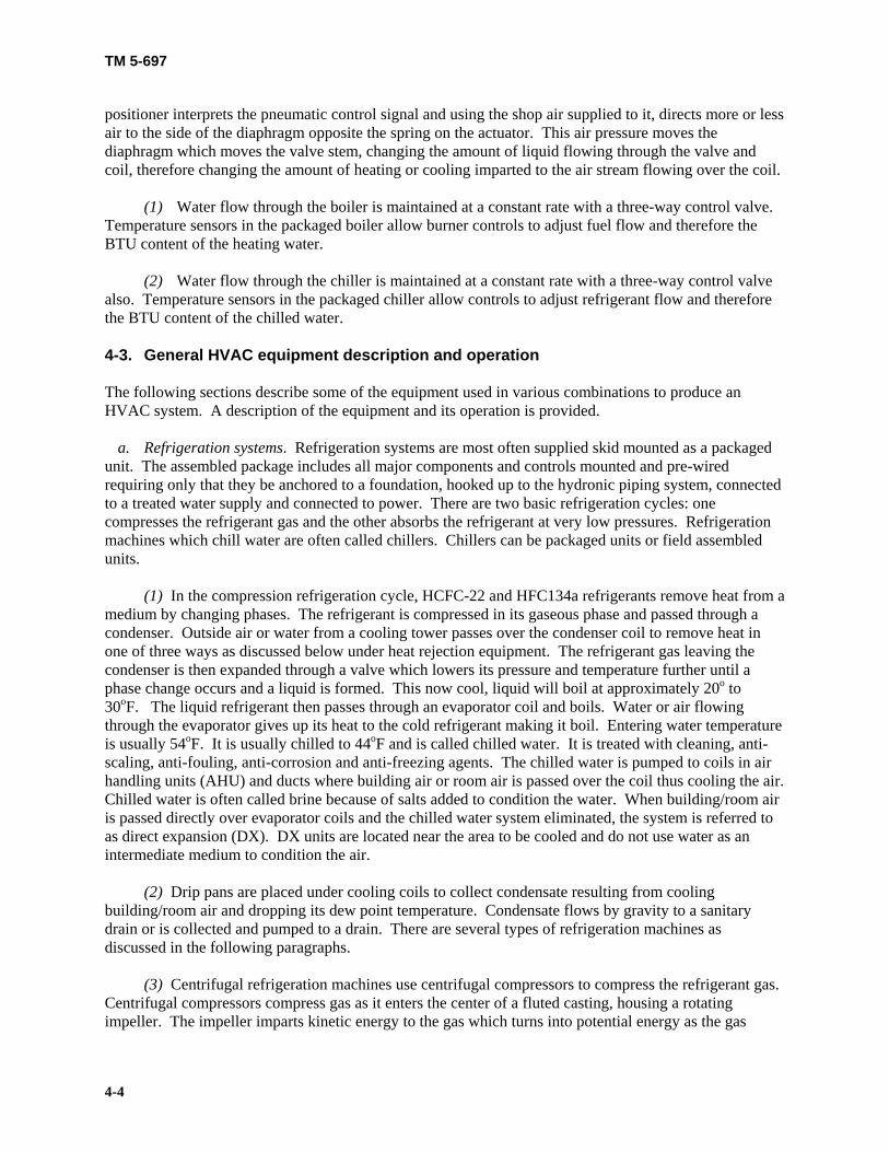
TM 5-697
4-4
positioner interprets the pneumatic control signal and using the shop air supplied to it, directs more or less air to the side of the diaphragm opposite the spring on the actuator. This air pressure moves the diaphragm which moves the valve stem, changing the amount of liquid flowing through the valve and coil, therefore changing the amount of heating or cooling imparted to the air stream flowing over the coil. (1) Water flow through the boiler is maintained at a constant rate with a three-way control valve. Temperature sensors in the packaged boiler allow burner controls to adjust fuel flow and therefore the BTU content of the heating water. (2) Water flow through the chiller is maintained at a constant rate with a three-way control valve also. Temperature sensors in the packaged chiller allow controls to adjust refrigerant flow and therefore the BTU content of the chilled water. 4-3. General HVAC equipment description and operation The following sections describe some of the equipment used in various combinations to produce an HVAC system. A description of the equipment and its operation is provided. a. Refrigeration systems. Refrigeration systems are most often supplied skid mounted as a packaged unit. The assembled package includes all major components and controls mounted and pre-wired requiring only that they be anchored to a foundation, hooked up to the hydronic piping system, connected to a treated water supply and connected to power. There are two basic refrigeration cycles: one compresses the refrigerant gas and the other absorbs the refrigerant at very low pressures. Refrigeration machines which chill water are often called chillers. Chillers can be packaged units or field assembled units. (1) In the compression refrigeration cycle, HCFC-22 and HFC134a refrigerants remove heat from a medium by changing phases. The refrigerant is compressed in its gaseous phase and passed through a condenser. Outside air or water from a cooling tower passes over the condenser coil to remove heat in one of three ways as discussed below under heat rejection equipment. The refrigerant gas leaving the condenser is then expanded through a valve which lowers its pressure and temperature further until a phase change occurs and a liquid is formed. This now cool, liquid will boil at approximately 20o to 30oF. The liquid refrigerant then passes through an evaporator coil and boils. Water or air flowing through the evaporator gives up its heat to the cold refrigerant making it boil. Entering water temperature is usually 54oF. It is usually chilled to 44oF and is called chilled water. It is treated with cleaning, anti-scaling, anti-fouling, anti-corrosion and anti-freezing agents. The chilled water is pumped to coils in air handling units (AHU) and ducts where building air or room air is passed over the coil thus cooling the air. Chilled water is often called brine because of salts added to condition the water. When building/room air is passed directly over evaporator coils and the chilled water system eliminated, the system is referred to as direct expansion (DX). DX units are located near the area to be cooled and do not use water as an intermediate medium to condition the air. (2) Drip pans are placed under cooling coils to collect condensate resulting from cooling building/room air and dropping its dew point temperature. Condensate flows by gravity to a sanitary drain or is collected and pumped to a drain. There are several types of refrigeration machines as discussed in the following paragraphs. (3) Centrifugal refrigeration machines use centrifugal compressors to compress the refrigerant gas. Centrifugal compressors compress gas as it enters the center of a fluted casting, housing a rotating impeller. The impeller imparts kinetic energy to the gas which turns into potential energy as the gas

TM 5-697
4-5
velocity slows, thus increasing pressure. Compression is a continuous process. One, two, or three stages may be used. Centrifugal compressors are used in large systems. (4) Reciprocating or positive displacement refrigeration machines use reciprocating or piston type compressors to compress the refrigerant gas. The gas enters a cylinder through a valve when a piston in the cylinder is going down. The valve closes when the piston starts to go up. As the piston approaches the top of the cylinder the gas is compressed by the decreasing volume. An exhaust valve opens when the piston is near the top of the cylinder allowing the compressed gas to exit. The cycle is then repeated. (5) Rotary screw refrigeration machines use rotary helical screw compressors to compress refrigerant gas or increase the pressure of liquid refrigerant. They are positive displacement machines. The twin-screw compressor consists of accurately matched rotors [one lobe (male) and one helix (female)] that mesh when rotating within a close tolerance common housing. One rotor is driven and geared to the other, turning it in a counter-rotating motion. (6) Scroll refrigeration machines employ a stationary scroll and a motor driven orbiting scroll to gather refrigerant gas at the circumference and move it through an ever decreasing volume to the center of the scroll where it exists at a higher pressure. (7) In absorption refrigeration machines the absorption cycle uses a heat-driven concentration difference to move refrigerant vapors (usually water) from the evaporator to the condenser. The high concentration side of the cycle absorbs refrigerant vapors, diluting the absorbent material, usually lithium bromide. Absorption refrigeration machines are typically found in large or small systems. Systems with medium cooling loads typically accomplish the demand through use of other types of cooling units. (8) In the evaporator, water at about 40°F is evaporating off the chilled water tubes, thereby bringing the temperature down from the 54°F being returned from the air handlers to the required 44°F chilled water supply temperature. The water vapor is absorbed by the concentrated lithium bromide solution due to its hygroscopic characteristics. The heat of vaporization and the heat of solution are removed using cooling water. The solution is then pumped to a concentrator at a higher pressure where heat is applied (using steam or hot water) to drive off the water and thereby re-concentrate the lithium bromide. (9) The water driven off by the heat input step is then condensed using cooling tower water, collected, and then flashed to the required low temperature of 40°F to complete the cycle. Since water is moving the heat from the evaporator to the condenser, it serves as the refrigerant in this cycle. (10) Lithium bromide is the most common absorbent used in commercial cooling equipment, with water used as the refrigerant. Lithium bromide has a very high affinity for water, is relatively inexpensive and non-toxic. However, it can be highly corrosive and disposal is closely controlled. Smaller absorption chillers sometimes use water as the absorbent and ammonia as the refrigerant. Ammonia absorption is used in recreational vehicles and food processing plants. (11) Absorption chillers must operate at very low pressures, about l/l00th of atmospheric pressure for the water to vaporize at the required ~ 40°F. (12) Absorption chillers are available in two types, single effect (stage) units using low pressure (20 psig or less) as the driving force and 9 psig steam at the generator, and double effect (two-stage) Units available as gas-fired or steam-driven with high pressure steam (40 to 140 psig). To achieve their

TM 5-697
4-6
improved performance they have a second generator in the cycle and require a higher temperature energy source. b. Heating systems. To heat building/room air, heating water coils are mounted in ducts. The heating water receives its heat directly from a hot water boiler or from a heat exchanger. Entering the heat exchanger is high temperature hot water or steam which provides heat for the heating water system. Building/room air can also be heated directly in an air heating furnace or by passing over the evaporator turned condenser in a direct exchange heat pump system. (1) Heating generators are most often supplied skid mounted as a packaged unit. The assembled package includes all major components and controls, mounted and pre-wired requiring only that they be anchored to a foundation, hooked up to the hydronic piping and duct systems, connected to a fuel supply and treated water supply, connected to a stack and connected to power. Following is a discussion of various heat generators. (2) Boilers burn natural gas, propane, oil or coal or use electric to produce steam, high temperature water and hot water. A boiler can be provided in each building for heating or a central location for heating a complex of buildings. In a firetube boiler, gaseous products of combustion pass through tubes surrounded by the water to be heated. In a watertube boiler, water passes through the tubes as the products of combustion passes over them. In an electric boiler, electric heating elements are inserted directly into the water. Depending on temperature and pressure the water will vaporize into steam, become high temperature water, or become hot water. Steam can be piped directly to individual room heaters of various types or can be used in a heat exchanger to condense, transferring the heat of vaporization to heating water. High temperature hot water boilers work in a similar fashion but produce high temperature water instead of steam. Hot water boilers produce hot water from 140 to 180oF for direct use in heating coils to heat building or room air. (3) Air heating furnaces burn natural gas, propane, or oil, or use electric to produce hot air to be used directly in heating building space or rooms. An air heating furnace is usually provided in each building for heating. When fuel is burned, the products of combustion are mixed with excess air and flow inside of a tube bundle or heat exchanger to heat the building/room air passing over the outside of the tube. When electric is used, heating elements are inserted directly into the air stream. (4) Heat pumps are discussed below in paragraph 4-3f, Unitary heat pump/air-conditioning equipment. c. Heat rejection equipment. Heat rejection equipment is most often supplied skid mounted as a packaged unit. The assembled package includes all major components and controls mounted and pre-wired requiring only that they be anchored to a foundation, hooked up to the piping system, connected to a treated water supply, and connected to power. A discussion of heat rejection equipment including cooling towers, evaporative condensers and air cooled condensers to remove heat from the condenser coil of a refrigeration machine follows. (1) Water from a cooling tower may be passed through the condenser to remove heat. Under full load conditions the design condenser cooling water inlet temperature is 85oF and leaving temperature is 95oF. The cooling tower water can then be directly exposed to outside air to reject heat from the water. This water is treated for corrosion, fouling, and scaling and is circulated from a basin in the bottom of the tower. Cooling towers may also use a closed loop for condenser water. A coil is installed in the tower; condenser water is pumped through it and therefore not exposed to the atmosphere. The water basin in

TM 5-697
4-7
the tower now provides water to spray over the tower coil. This with the assistance of a fan removes heat from the condenser water. This basin water is also treated for corrosion, fouling, and scaling. (2) An evaporative condenser is placed directly over a basin, water from the basin is sprayed, and air is forced over the coils resulting in cooling of refrigerant in the coils. At full load conditions the design entering air dry bulb temperature is usually 95oF and entering air wet bulb temperature is 75oF. (3) An air cooled condenser has outside air passed over it, the refrigerant in the coil is cooled directly by the air. At full load conditions the design entering air dry bulb temperature is 95oF. Entering condenser refrigerant vapor temperature is 190oF. Leaving condenser refrigerant temperature is 125oF. d. Air handling equipment and systems. Air handling equipment is designed to condition air in rooms or in designated areas in a building called zones. In an AHU air is moved through filters and over coils to clean, heat or cool it. Fluid flow in coils or air flow through the AHU can be adjusted for interior environmental control. Following are variations of AHUs. (1) A single-zone AHU controls interior building air in one building zone. There may be several rooms in one zone. (2) Multi-zone AHUs control interior building air in two or more building zones. (3) A variable air volume (VAV) AHU controls interior building air by varying air flow over the coils as opposed to the usual way of varying the flow of the heating water and chilled water through the coils. (4) A terminal unit VAV (dual duct) unit is located at the end of a heating air and cooling air supply duct and controls interior building air by varying the air volume and mix. (5) A terminal unit dual duct fan series AHU is located at the end of a heating air and cooling air supply duct and controls interior building air by varying the air volume with the use of local fan(s). (6) Terminal units with cooling are located at the end of a heated or non-heated air supply duct and include a cooling coil for control of interior building air. (7) Terminal units with and without fans are located at the end of a conditioned air supply duct and may or may not include a fan for control of interior building air. (8) DX air units control interior building air by using a DX coil in the air stream. In the DX coil the fluid flowing inside of the coil is a refrigerant. Generally this coil is for cooling but it can be used for heating as well. (9) Fan coil units are AHUs which control interior building air with a coil to change air temperature and a fan to force the air over the coil and into the building. (10) Unit heaters usually employ a fan to circulate air within an area or zone and have no supply or return air duct or system of ducts. To control building air, steam coils, hot water coils, electrical elements, or direct gas fired heat exchangers may be used for heating.

TM 5-697
4-8
(11) Radiant heaters use gas and sometimes electric to heat a ceramic surface. Heat is transferred by radiation to the floor and objects in the room which then heat air by free convection instead of forced convection as is accomplished in most AHUs. (12) Base heater units consist of an electric element or a finned tube with hot water flowing inside the tube. These units heat interior air by free convection or sometimes incorporate a fan to heat air by forced convection. They heat air in the local vicinity of the heater. (13) A computer room unit is prepared for controlling the environment in a computer room. This includes provisions for filtering, heating, cooling and humidity control. Humidity control is usually provided by increased cooling capacity and reheating of the air through additional heating capacity. (14) A packaged roof top unit is an AHU with its duct, coils, fans and controls packaged in a weather proof box and is provided with weather proof components to withstand the elements. It is also designed to be supported on a roof with supply and return air ducts located on the bottom of the unit. (15) An economizer is a gas-to-gas, liquid-to-gas or liquid-to-liquid heat exchanger which, when practical, is used to salvage waste heat from a process or part of an HVAC system. The waste heat is used to pre-heat heating air thereby reducing the amount and cost of heating. The heating system is therefore more economical to operate with an economizer installed. (16) Variable speed fans are used in units where a variable volume of air flow is required. Variable speed fans may be provided in place of a central fan and may incorporate inlet guide vanes and/or modulating dampers. e. Unitary heat pump/air-conditioning equipment. Unitary heat pumps are factory-packaged refrigerant based units. They can provide cooling or heating of interior building air. Both heating and cooling of air can be provided if a refrigerant reversing valve and associated controls are included. This valve reverses the flow of refrigerant transforming the evaporator into a condenser and the condenser into an evaporator. In this way heat can be moved (pumped) from inside building air to the outside in the summer, and from the outside to inside building air in the winter. Provisions are provided to collect condensate from cooling interior air and connection to a drain is needed. Heat pumps and air- conditioning equipment are available in a number of application categories which include the following. (1) A packaged terminal heat pump (PTHP) unit is designed to be installed at the end of a building interior air supply duct. It includes appropriate duct connections, coils, fans and controls packaged in one box. It is also designed to be supported from overhead. (2) Single packaged units have their duct, coils, fans and controls packaged in one weather proof box and are provided with weather proof components to withstand the elements. They are designed to be located outside and supported on a concrete pad or steel frame from the bottom with supply and return air ducts located horizontally or vertically. Console under window units are also available without duct connections. (3) A roof-top packaged unit has its duct, coils, fans and controls packaged in a weather proof box and is provided with weather proof components to withstand the elements. It is also designed to be supported on a roof with supply and return air ducts located on the bottom of the unit. (4) Split heating, air conditioning, and heat pump units have their ducts, coils, fans and controls packaged in two boxes. A weather proof exterior box for the compressor, condenser coil, condenser fan

TM 5-697
4-9
and controls is designed to be supported on a concrete pad or steel frame from the bottom. An interior box is provided with supply and return air duct connections, fan and drip pan. Connections for refrigerant tubing are provided on both boxes. This tubing is routed as needed and insulated to prevent heat loss or gain in the refrigerant and to prevent condensate from forming on the tubing. (5) Ground source heat pumps (GSHP) are typically installed indoors. One box contains the compressor, pump, fans, duct connections and controls, but often components are not included in the central box to adapt the system for the user’s needs. The box is connected to underground piping networks that exchange heat with the ground. These pipes can be closed loops, buried only feet underground or connected to sources of water such as wells or ponds. A desuperheater can also be employed during the summer months to extract heat from the conditioned air for hot water heating. f. HVAC control systems. HVAC control systems are used to control heating, cooling, and ventilating of interior building/zone/room air and are also used in fire safety control schemes. (1) Direct digital control (DDC) HVAC control systems use sensors, electric actuators, and microprocessors to provide a marked upgrade in system functionality over that attainable with pneumatic control. DDC systems provide operators the ability to remotely monitor existing conditions, change setpoints, diagnose and sometimes fix problems from a workstation or laptop PC. A single operator could monitor many buildings with DDC control, in addition to performing other operating and maintenance (O & M) tasks. Energy management and reporting functions improve operational efficiency and cost savings. Operational problems can be identified early and fixed before they become larger and more expensive. DDC systems involve vendor-specific application software and a communications network. Each software application provides varying degrees of flexibility and a unique software approach to DDC. The systems are often incompatible. (2) Fire safety air moving systems provide fire safety to air zones and to stairwells by moving air or smoke. These systems provide for smoke removal only or air pressurization only to help keep areas clear of smoke and provide fire control. They may also use a combination of smoke removal with air pressurization to isolate an air zone for fire safety control. (3) EMCS manage heating and cooling in a building or zone of a building according to programmed time and temperature schemes for efficient use of energy. (4) Hydronic systems supply controlled chilled and heated water to cooling or heating coils. In hydronic systems an air separator is incorporated to remove air from the water and an expansion tank is provided to account for changing density in the water. Secondary piping systems are used to circulate water in secondary loops located in different buildings or zones which branch off of the main or primary heating or cooling water supply loop. (5) Ventilation systems provide circulation of controlled conditioned and filtered air to building zones or rooms and incorporate exhaust air relief and make-up outside air. g. Smoke management systems. HVAC systems can interface with fire detection/alarm systems. When HVAC control systems interface with fire systems, signals from the fire system are used to take action to minimize the fire and/or provide safe shut down of equipment. (1) Smoke management systems can use smoke dampers to inhibit the passage of smoke from one zone to another. By appropriate opening and closing of smoke dampers in HVAC ducts, building zones free of fire can be pressurized with air while the zone with the fire can have smoke pulled from it.

TM 5-697
4-10
(2) Fire dampers are dampers which close when a fuseable link melts and permits the damper to close. This prevents air movement in the duct which helps limit the fire and prevents smoke from flowing in the duct. (3) Fire stops and smoke barriers are fixed obstacles provided to stop the movement of fire or smoke in walls or ceilings. (4) Automatic and manual control can be used in HVAC control systems for fire safety and smoke management. Air distribution systems have manually operated devices that stop the operation of supply, return and/or exhaust air and fans in an emergency. Automatic shutdown capability automatically, according to a predetermined fire management plan, closes dampers and shuts down fans when detectors located in the supply ducts, return ducts or the building fire protection system detect a fire. (5) Proper gasketing and sealing of doors is needed to prevent air infiltration into a zone during a fire. (6) Door release hardware and automatic door openers provide for opening doors for human egress and to control fire and smoke as predetermined in a fire management plan. h. Ducting. HVAC ducts come in various configurations including round, square, rectangular and round oval. They are made from iron, concrete, galvanized steel, rigid fibrous and flexible materials. Metal ducts which supply cooling air must be insulated. Duct systems must be tested for leaks and cleaned before being put into service. Ducts can incorporate heating coils, cooling coils, DX coils, flow switches, pressure switches and gages, smoke detectors, heat detectors and dampers for system control. i. Piping systems. Piping systems supply steam, high temperature water and hot water for heating and chilled water for cooling. These systems also provide make-up water to boilers and return steam condensate to boilers. Condensate from cooling coils is taken to a drain by pipe systems. Pumps move fluids, and steam is moved by pressure differential. (1) Pipe systems may include steam/hot water converters which heat water with steam by using a heat exchanger, finned tube radiators which heat room air by natural convection, control valves operated by the HVAC control system for shutting off and controlling fluid flow, solenoids electrically actuated for stopping fluid flow, and relief valves to prevent over pressure of vessels and systems. Hydronic piping systems incorporate air separators and expansion tanks and must be adjusted and balanced before being put into service. Piping systems must be hydrostatically tested for leaks before being put into service. Piping can incorporate flow switches, pressure switches and gages, thermometers and thermo-wells, solenoids and relief valves for system control. (2) Piping systems come in four types: 1-pipe, 2-pipe, 3-pipe and 4-pipe. The limitation of 1 and 2-pipe systems is that they can only operate in one mode at a time; heating is typically provided for a portion of the year while cooling is provided for the remainder. In 3 and 4-pipe systems, different users in the same building can call for heat or cooling at the same time, Two and 4-pipe systems are more efficient and consequently more expensive that their respective 1 and 3-pipe pairs. 4-4. Pre-functional test plan and functional performance test plan for HVAC systems This manual assumes that individual components and packaged equipment has been tested by the manufacturer. As part of the commissioning effort each component should be checked for damage,

TM 5-697
4-11
deterioration and failures by a procedure using inspections and tests defined by the specific equipment manufacturers. Equipment manuals from manufacturers identify the minimum required receipt inspections, handling and installation procedures, drawing and wiring verification, field inspection and installation checks, verification of removal of shipping braces, inspection of installation against drawings and nameplates, inspection of components for damage and cleanliness, inspection of insulators and grounding, inspection of anchorage and alignment, adjustment checks, mechanical operation and interlock checks, lubrication application and verification that local safety equipment is in place. a. Safety, HVAC. Many tests on equipment involve the use of high voltages, high currents, high pressures, high temperatures and rotating or moving equipment. These can be dangerous to personnel and damaging to equipment. A procedure should be followed to insure adequate safety rules are instituted and practiced to prevent injury to personnel performing the tests and other personnel who might be in the local area. b. Test equipment, HVAC. It is important that in any test program the proper equipment is used. The equipment should be calibrated, in good condition and used by qualified operators as required by a procedure. Any test equipment used for calibration shall have twice the accuracy of the equipment to be tested. All equipment should be operated in accordance with its instruction manual. c. Procedures, HVAC. A procedure defining installation inspection and a system test needs to be provided for each system. In the HVAC system there are three basic systems: a heating water system, a chilled water system and a building air or ventilating system. d. Inspection checklists, HVAC. Inspection checklists for HVAC systems are presented in figure 4-3, Example of a completed DA Form 7477-R, heating water system inspection checklist; figure 4-4, Example of a completed DA Form 7478-R, chilled water system inspection checklist and figure 4-5, Example of a completed DA Form 7479-R, ventilation system inspection checklist. They are filled out to serve as examples of typical equipment conditions. For convenience, these checklists are included unpopulated at the end of this technical manual. e. HVAC equipment detail. Further commissioning pre-functional test and functional performance test detail for equipment, components, and HVAC systems are found in the Department of Commerce: NISTIR 4758, NTIS PB92-173012INZ, HVAC Functional Inspection and Testing Guide and the Department of Energy: Model Commissioning Plan and Guide Specifications, USDOE, Version 2.05 Sections 15998 and 15999. 4-5. Possible failures and corrective measures for HVAC systems Table 4-1 on page 4-16 lists general problems that may arise during the testing of equipment and systems along with possible troubleshooting techniques. For all problems, consult equipment and component manuals for troubleshooting directions. Check fuses/lights/breakers/etc. for continuity; check equipment calibration and settings; check for clogged filters and strainers; check for closed manual shut-off valves and dampers; check for improperly adjusted valves, dampers and equipment and look for faulty equipment and connections.

TM 5-697
4-12
Figure 4-3: Example: DA Form 7477-R
EXTERIOR OF EQUIPMENTCOMPLETENESS OF ASSEMBLYEQUIPMENT ROTATIONELECTRICAL/MECHANICAL INTERLOCKSINSTRUMENTSPROPER GROUNDINGPROPER INSULATIONTIGHTNESS OF BOLTED CONNECTIONSPROPER LUBRICATIONWATER TREATMENT
RAAARAARA
NA
1. PLANT East Building
HEATING WATER SYSTEM INSPECTION CHECKLISTFor use of this form, see TM 5-697; the proponent agency is COE.
SECTION A - CUSTOMER DATA
DA FORM 7477-R, DEC 2002 USAPA V1.00
2. LOCATION Washington, DC
3. JOB NUMBER EB-18
4. EQUIPMENT 5. HEATING WATER LOOP DESIGNATION HHW-02
6. DATE (YYYYMMDD) 20021125
7. TEST EQUIPMENTRitchie gas menometer kit, Fluke calibrated multimeter
8. TESTED BY Roger Swanson
SECTION B - EQUIPMENT DATA9. BOILER MANUFACTURERYork Shipley
10. MODEL NOSPL 500-6-97493
11. SERIAL NO63-8384 H32093
12. BTU RATINGNA
13. PUMP MANUFACTURERBell & Gossett
15. SERIAL NO87-2602-AG
SECTION C - VISUAL AND MECHANICAL INSPECTION
COND* NOTESCHECK POINT
EQUIPMENT IDENTIFICATIONBRACINGLABELING AND TAGGINGSAFETY INTERLOCKSWORKING SPACEANCHORAGESYSTEM FLUSHED AND CLEANEDCOMPARISON TO DRAWINGSCONTROL SYSTEMFUEL SYSTEM
AAAAAAR
NAAA
COND* NOTESCHECK POINT
SECTION D - CALIBRATION AND SET POINT
*CONDITION: A=ACCEPTABLE; R=NEEDS REPAIR, REPLACEMENT OR ADJUSTMENT; C=CORRECTED; NA=NOT APPLICABLE
23. NOTES1. Boiler is cycling as would be expected.2. Operating range checked through the purge cycle, low fire, and high fire postions.3. Steam relieved as expected and the valve reseated after the manually applied pressure was removed.
20.
14. MODEL NOBG-452
16. RATED FLOW25 gpm
18. RATED NPSH17. HP @ RPM 19. RATED PRESSURE30 psi
SENSORSCONTROLLERSACTUATORSRELIEF VALVES CHECKEDFUEL SAFETY VALVES
21.
Photocell signal level within manufacturers tolerancesFireye controller does not indicate any faults.Burner Modulating Motor operating renge appears to be OK. See note.Relief valve was manually forced open during operation.Gas Train safeties were checked. All safeties functioned appropriately.
DESCRIPTION
123
NOTES
BOILERPUMPHYDROSTATIC TESTBALANCE TESTHEATING COIL NUMBERCONTROL VALVESSYSTEM TEST
22. NOTESOPERATING MODES
300 degrees F 15 psi NA
TEMPERATURES PRESSURES FLOWS LEVELS
AutoAuto
performed annuallyNANANA
performed annually
190 degrees F 15 psi NA
SECTION E - HYDRONIC SYSTEM TESTS

TM 5-697
4-13
Figure 4-4: Example: DA Form 7478-R
EXTERIOR OF EQUIPMENTCOMPLETENESS OF ASSEMBLYEQUIPMENT ROTATIONELECTRICAL/MECHANICAL INTERLOCKSINSTRUMENTSPROPER GROUNDINGPROPER INSULATIONTIGHTNESS OF BOLTED CONNECTIONSPROPER LUBRICATIONREFRIGERANT INSTALLED
RAAARAARA
NA
1. PLANT East Building
CHILLED WATER SYSTEM INSPECTION CHECKLISTFor use of this form, see TM 5-697; the proponent agency is COE.
SECTION A - CUSTOMER DATA
DA FORM 7478-R, DEC 2002 USAPA V1.00
2. LOCATION Washington, DC
3. JOB NUMBER EB-19
4. EQUIPMENT Carrier System
5. COOLING WATER LOOP DESIGNATION 6. DATE (YYYYMMDD) 20021125
7. TEST EQUIPMENT 8. TESTED BY Roger Swanson
SECTION B - EQUIPMENT DATA9. CHILLER MANUFACTURERCarrier
10. MODEL NO19XR
11. SERIAL NO9210H6115
12. BTU RATING4254 kW
13. PUMP MANUFACTURERCummins - Wagner
15. SERIAL NO1510
SECTION C - VISUAL AND MECHANICAL INSPECTION
COND* NOTESCHECK POINT
EQUIPMENT IDENTIFICATIONBRACINGLABELING AND TAGGINGSAFETY INTERLOCKSWORKING SPACEANCHORAGESYSTEM FLUSHED AND CLEANEDCOMPARISON TO DRAWINGSCONTROL SYSTEMWATER TREATMENT INSTALLED
AAAAAAR
NAAA
COND* NOTESCHECK POINT
SECTION D - CALIBRATION AND SET POINT
*CONDITION: A=ACCEPTABLE; R=NEEDS REPAIR, REPLACEMENT OR ADJUSTMENT; C=CORRECTED; NA=NOT APPLICABLE
23. NOTES
20.
14. MODEL NO6BC
16. RATED FLOW1,898 gpm
18. RATED NPSH55
17. HP @ RPM40 @ 1770
19. RATED PRESSURE165 kPa
SENSORSCONTROLLERSACTUATORSRELIEF VALVES CHECKED
SECTION E - HYDRONIC SYSTEM TESTS
21.
Pressure, temperature, and condition sensors checked OKCarrier control system interfaces with JCI system.Exercise annually for valve control.Exercise annually for valve operation limits.
DESCRIPTION NOTES
CHILLERPUMPHYDROSTATIC TESTBALANCE TESTCOOLING COIL NUMBEREXPANSION TANK/AIR SEPARATORCONTROL VALVESSYSTEM TEST
22. NOTESOPERATING MODES TEMPERATURES PRESSURES FLOWS LEVELS
AutoAuto
performed annuallyNANANANA
performed annually

TM 5-697
4-14
Figure 4-5: Example: DA Form 7479-R
EXTERIOR OF EQUIPMENTCOMPLETENESS OF ASSEMBLYEQUIPMENT ROTATIONELECTRICAL/MECHANICAL INTERLOCKSINSTRUMENTSPROPER GROUNDINGPROPER INSULATIONTIGHTNESS OF BOLTED CONNECTIONSPROPER LUBRICATIONCONDENSATE DRIP PANS
AAAAAAAAAA
1. PLANT East Building
VENTILATION SYSTEM INSPECTION CHECKLISTFor use of this form, see TM 5-697; the proponent agency is COE.
SECTION A - CUSTOMER DATA
DA FORM 7479-R, DEC 2002 USAPA V1.00
2. LOCATION Washington, DC
3. JOB NUMBER EB-41
4. EQUIPMENT 5. AIR LOOP DESIGNATION Section C
6. DATE (YYYYMMDD) 20021204
7. TEST EQUIPMENTAir flow meter, electrical meter, temperature meter
8. TESTED BY Roger Swanson
SECTION B - EQUIPMENT DATA9. FAN MANUFACTURERGreenheck
10. MODEL NOG-120-B
11. SERIAL NO73662
12. RATED FLOW980 cfm
SECTION C - VISUAL AND MECHANICAL INSPECTION
COND* NOTESCHECK POINT
EQUIPMENT IDENTIFICATIONBRACINGLABELING AND TAGGINGSAFETY INTERLOCKSWORKING SPACEANCHORAGESYSTEM CLEANEDCOMPARISON TO DRAWINGSCONTROL SYSTEMFILTERS
AARAAAARRR
COND* NOTESCHECK POINT
SECTION D - CALIBRATION AND SET POINT
*CONDITION: A=ACCEPTABLE; R=NEEDS REPAIR, REPLACEMENT OR ADJUSTMENT; C=CORRECTED; NA=NOT APPLICABLE
19. NOTES
16.
14. HP @ RPM 1 hp @ 1200
13. FAN TYPECentrifugal
15. RATED PRESSURE125 static
SENSORSCONTROLLERSACTUATORSFIRE DAMPERS CHECKEDSMOKE DAMPERS CHECKED
SECTION E - SYSTEM TESTS
17.
Checked sensors with standardCycled controllers for responseChecked full operation from fully open to fully closedActuated fire dampers. Checked for proper operation.Actuated smoke dampers. Checked for proper operation.
DESCRIPTION NOTES
FANDUCT LEAK TESTAIR BALANCE TESTCOIL NUMBERCOIL NUMBERCONTROL DAMPERSSYSTEM TEST
18.NOTESOPERATING MODES
68 to 72 F .125 980
TEMPERATURES PRESSURES FLOWS LEVELS
Speeds as requiredOn at high speed
As requiredOnOn
Moderation of flowNormal operation
68 to 72 F68 to 72 F68 to 72 F
NA
.125
.125
.125
.125NA
980980980980NA
68 to 72 F NA NA

TM 5-697
4-15
Table 4-1. Possible failures and corrective actions of HVAC system
Areas to Check General Controls Devices will not close/trip
Check mechanical alignment of limit switches Check interlocks and safeties Check relay and protective device settings and operation Check for mis-wired circuits Check control circuit Check controller set point
Devices trip inadvertently
Check relay and protective device settings and operation Check for mis-wired circuits Check the control circuit Check for system overload or short Check grounds
Boiler Will not start or starts but shuts down
Check PLC Check power supply Check controls, switches, starters, and disconnects Check controller set points Check sensors, actuators, and indicators Check fuel supply Check fuel safety valves Check fuel filters Check burner flame safety Check igniter Check blower and blower inlet Check heating water pump, flow and control valve Check feed water supply Check safeties and interlocks to fire protection systems
Incorrect heating water temperature
Check controls and set point Check heating water pump, flow and control valve Check for closed shut off valves

TM 5-697
4-16
Table 4-1. Possible failures and corrective actions of HVAC system (continued)
Chiller Will not start or shuts down
Check Program Logic Controller (PLC) Check power supply Check controls, switches, starters, and disconnects Check controller set point Check sensors, actuators, and indicators Check refrigerant Check refrigerant heaters Check condenser fans Check heat rejection equipment power, pumps, fans, and controls Check water pump, flow and control valve Check safeties and interlocks to fire protection systems
Incorrect cooling water temperature
Check sensors, controllers and set point, actuator/positioners Check chilled water pump, flow and control valve Check expansion tank and air separator Check for closed shutoff valves
Ventilating Fan Will not start or shuts down
Check power supply Check controls, switches, starters, and disconnects Check inlet vane and damper actuators Check filter(s) Check safeties and interlocks to fire protection systems
Vibrates Check motor and fan bearings Check inlet vane and dampers Check impeller condition Check vibration joints and isolators Check air filter(s)
Valves and Dampers Will not move Check for stuck valve stem or damper shaft
Check supply air Check positioner linkage adjustment Check pneumatic signal Check actuator shaft, diaphragm, and spring Check controller and controller set point Check safeties and interlocks to fire protection systems

TM 5-697
5-1
CHAPTER 5
GENERATORS AND ANCILLARY EQUIPMENT ____________________________________________________________ 5-1. Description of generator ancillary equipment, diesel fuel, and lube oil systems Generators are used to supply primary power, standby power and emergency power. The generators used at command, control, communications, computers, intelligence, surveillance and reconnaissance (C4ISR) facilities are most often powered by diesel engines. Commissioning of a standby power system addressing the generator and electrical aspects of standby power are discussed in Army TM 5-694. This technical manual will address the ancillary equipment consisting of a typical diesel fuel and lube oil system. a. Diesel fuel system. A diesel fuel system is shown in figure 5-1, Schematic of a typical diesel fuel system. The system consists of a storage tank, strainer, motor driven pump, filter, expansion tank, heater, day tank, cooler, engine mounted duplex filter and engine mounted pump.
LI
FILL
LI
HEATER
VENT
OVERFLOW
GRAVITYSUPPLY
SUPPLY
DAYTANK
DIESELENGINE
ENGINEPUMP
DUPLEXFILTERSHOT WATER
SUPPLY
COOLER
F
EXPANSIONTANK
RETURN
STORAGE TANK
MAN ACCESSPORT
STRAINER
PUMP FILTER
Figure 5-1. Schematic of a typical diesel fuel system
b. Lube oil system. A lube oil system is shown in figure 5-2, Schematic of a typical lube oil system. The system consists of a clean lube oil tank, dirty lube oil tank, pumps, lube heaters, cooler, centrifuge, duplex filter and duplex strainer.

TM 5-697
5-2
LUBE OILSUMP
LI
FILL
TANK VENT(TYP)
CLEAN LUBEOIL TANK
FOOT VALVE(TYP)
STRAINER(TYP)
PUMP(TYP)
LI
TANK HEATER(TYP)
DRAIN
DIRTY LUBETO RECYCLE
WATER/OILTO SEPARATOR
SLUDGE TOTREATMENT
HEATER
CENTRIFUGE
DUPLEX FILTER
ENGINE
DUPLEX STRAINER
ELECTRIC MOTORDRIVEN PRELUBE
PUMP
ENGINE DRIVENLUBE OIL PUMP
HEATER
COOLER
THERMOSTATICVALVE
Figure 5-2. Schematic of a typical lube oil system
c. Diesel fuel and lube oil systems. More information on design, maintenance, and testing of diesel fuel and lube oil systems and generators is found in the American Society of Mechanical Engineers (ASME): B 31.3, Process piping, Army TM 5-692-1 Maintenance of Mechanical and Electrical Equipment at C4ISR Facilities, Recommended Maintenance Practices, chapters 5, 6 and 19, Army TM 5-692-2 Maintenance of Mechanical and Electrical Equipment at C4ISR Facilities, System Design Features, chapters 5, 6 and 19, Army TM 5-685 Operation, Maintenance and Repair of Auxiliary Generators and Army TM 5-694 Commissioning of Electrical Systems for C4ISR Facilities, chapter 5. 5-2. Operation of diesel fuel system and lube oil systems A discussion of the operation of the diesel fuel and lube oil systems is presented in the following paragraphs. a. Diesel fuel system operation. The diesel fuel storage tank shown in figure 5-1, Schematic of a typical diesel fuel system, must be a double wall tank or, when located above ground, a single wall tank surrounded by a dike for containment of a leak, can be used. For underground installations, the tank must be double wall with a leak detection system monitoring the annulus between walls. The tank is provided with level indication, either local, remote, and/or is interlocked to shut off fill flow. The tank is provided with a fill line, man access port, return line and two suction lines. The tank may be provided with suction line heaters or a tank heater (not shown) depending on the engine’s fuel requirement and type of diesel fuel selected. The fill line and the return lines are provided with traps to minimize the formation of vapors in the tank. One suction line is located higher than the other. Normally the pump will draw from the low suction line. As water separates from the fuel it will approach the lower suction line. If water is picked up in this line, the pump can be switched to the upper suction line until the water is removed through the man access port. A strainer provides a coarse means of particulate removal upstream of the pump. A coalescing filter provides for water and fine particulate removal downstream of the pump. An expansion tank may be installed to prevent expanding fuel oil from leaking from joints and shaft seals. An oil heater may be installed depending on the type of oil and climate, to reduce oil viscosity to the
TM 5-697
5-3
atomizing range. The fuel oil then enters the day tank and is discharged through a trap. The day tank holds a four- to eight- hour supply of fuel and is mounted above, or in close proximity to, the generator’s diesel engine. It is provided with a vent, overflow, return line, gravity feed line to the duplex engine filters, a pump and a level indication, either local, remote and/or interlocked to shut off supply flow. The engines positive displacement pump raises the diesel fuel to the correct pressure for engine operation and distributes it to the fuel injectors. An oil cooler is provided, when needed, in the return line to minimize flashing and formation of vapors. Oil lines may be electrically or steam heat traced for winter service depending on the type of fuel, climate and installed pipe location. b. Lube oil system operation. As shown in the lube oil system in figure 5-2, Schematic of a typical lube oil system, new lube oil passes through a strainer before entering the clean lube tank. The tank is provided with level indication, either local, remote and/or is interlocked to shut off fill flow. The tank is also equipped with a vent and a heater if required. The dirty lube tank incorporates a drain, level indication, vent, return line and suction line. (1) A pump draws lube oil through a strainer and foot valve in either tank. The foot valve prevents the line from emptying when not in use. From this pump, lube oil can flow to the engine lube oil sump, to a tanker truck for hauling to an oil recycle center, or it can be heated and cleaned through a centrifuge. From the centrifuge, water/oil discharge is sent to a separator, sludge is sent to treatment for disposal and the treated lube is sampled. The treated lube if clean is pumped to the engine lube oil sump, or if dirty it is pumped to the dirty lube oil tank. (2) From the engine lube oil sump, lube oil is pumped through a duplex strainer by a motor driven pump or an engine driven pump. As with duplex filters, duplex strainers provide for continuous operation. Switching from one strainer to the other can take place without impeding oil flow by switching the inlet and outlet three-way valves simultaneously. This permits cleaning of one strainer while the other is in service. When the standby power engine requires warm engine lube and a warm engine block for startup, the electric motor driven pump continuously circulates engine lube through a heater. Once the engine is started the engine driven lube oil pump will take over and lube will flow through a thermostatic valve to a cooler and by-pass line to maintain correct engine lube temperature for operation. The lube oil flows through a duplex filter before entering the engine. The electric motor driven pump can also be used as a pre-lube pump to circulate lube prior to starting the engine and after the engine shuts down for controlled cooling. The pump also transfers dirty lube from the engine lube oil sump to the dirty lube oil tank. (3) The lube oil system may be integral with the engine or may be provided as a separate skid mounted unit. Lube oil tanks, pipes, and lines may be heated or heat traced. Controls, alarms and engine shutdown interlocks are provided as needed and include alarms for low oil flow, low oil level, low oil pressure, low oil temperature, high oil temperature or high filter differential pressure. 5-3. Pre-functional test plan and functional performance test plan for diesel fuel and lube oil systems This manual assumes that individual components and packaged equipment have been tested by the manufacturer. As part of the commissioning effort each component should be checked for damage, deterioration, and failures by a procedure using inspections and tests as defined by the specific equipment manufacturers. Equipment manuals from manufacturers identify the minimum required receipt inspections, handling and installation procedures, drawing and wiring verification, field inspection and installation checks, verification of removal of shipping braces, inspection of installation against drawings and nameplates, inspection of components for damage and cleanliness, inspection of insulators and

TM 5-697
5-4
grounding, inspection of anchorage and alignment, adjustment checks, mechanical operation and interlock checks, lubrication application and verification that local safety equipment is in place. a. Safety, diesel fuel and lube oil systems. Many tests on equipment involve the use of high voltages, high currents, pressurized fuel and rotating or moving equipment. These can be dangerous to personnel and damaging to equipment. A procedure should be followed to insure adequate safety rules are instituted and practiced to prevent injury to personnel performing the tests and other personnel who might be in the local area. b. Test equipment, diesel fuel and lube oil systems. It is important that in any test program the proper equipment is used. The equipment should be calibrated, in good condition, and used by qualified operators as required by a procedure. Any test equipment used for calibration shall have twice the accuracy of the equipment to be tested. All equipment should be operated in accordance with its instruction manual. A procedure defining installation inspection and a system test needs to be provided. c. Inspection checklists, diesel fuel and lube oil systems. An inspection checklist for the systems are presented in figure 5-3, Example of a completed DA Form 7480-R, diesel fuel system inspection checklist and figure 5-4, Example of a completed DA Form 7481-R, lube oil system inspection checklist. They are filled out to serve as examples of typical equipment conditions. For convenience, these checklists are included unpopulated at the end of this technical manual. 5-4. Possible failures and corrective measures for diesel fuel and lube oil systems Table 5-1 on page 5-7 lists general problems that may arise during the testing of equipment and systems along with possible troubleshooting techniques. For all problems, consult equipment and component manuals for troubleshooting directions. Check fuses/lights/breakers/etc., for continuity, check equipment calibration and settings, check for clogged filters and strainers, check for closed manual shutoff valves and dampers, check for improperly adjusted valves and equipment, and look for faulty equipment and connections.

TM 5-697
5-5
Figure 5-3: Example: DA Form 7480-R
EXTERIOR OF EQUIPMENTCOMPLETENESS OF ASSEMBLYEQUIPMENT ROTATIONELECTRICAL/MECHANICAL INTERLOCKSINSTRUMENTSPROPER GROUNDINGPROPER INSULATIONTIGHTNESS OF BOLTED CONNECTIONSPROPER LUBRICATION
AAAAAA
NAA
NA
1. PLANT Redundant Power
DIESEL FUEL SYSTEM INSPECTION CHECKLISTFor use of this form, see TM 5-697; the proponent agency is COE.
SECTION A - CUSTOMER DATA
DA FORM 7480-R, DEC 2002 USAPA V1.00
2. LOCATION Building 10
3. JOB NUMBER RP-22
4. EQUIPMENT Fuel Oil System - 1
5. SYSTEM DESIGNATION FOS - 1
6. DATE (YYYYMMDD) 20021125
7. TEST EQUIPMENTGraduated Story pole, tank level chart, Fluke multimeter
8. TESTED BY Bob Hale
SECTION B - EQUIPMENT DATA9. PUMP MANUFACTUREROberdorfer
10. MODEL NON993-03
11. SERIAL NOT10063
12. FLOW RATING GPM8 gpm
16. HEATER MANUFACTURER 18. SERIAL NONA
SECTION C - VISUAL AND MECHANICAL INSPECTION
COND* NOTESCHECK POINT
EQUIPMENT IDENTIFICATIONBRACINGLABELING AND TAGGINGSAFETY INTERLOCKSWORKING SPACEANCHORAGELEAKSCOMPARISON TO DRAWINGSCONTROL SYSTEM
AAAAAAA
NAA
COND* NOTESCHECK POINT
SECTION D - CALIBRATION AND SET POINT
*CONDITION: A=ACCEPTABLE; R=NEEDS REPAIR, REPLACEMENT OR ADJUSTMENT; C=CORRECTED; NA=NOT APPLICABLE
27. NOTES1. Tank level was taken with Story pole and calculatefd using tank chart.
24.
17. MODEL NONA
19. FLOW RATE GPMNA
14. HP @ RPMNA
13. TYPEGear Pump
15. PRESSURE RATING PSIGNA
SENSORSCONTROLLERSACTUATORS
SECTION E - DIESEL FUEL SYSTEM TESTS
25.
Main tank levels are consistent with sensor reading.Main tank controllers indicate all conditions normalNA
DESCRIPTION
1
NOTES
PUMPHEATERCOOLERENGINEHYDROSTATIC TESTSYSTEM TEST
26.NOTESOPERATING MODES
55 degrees F 3 psi 8 gpm
TEMPERATURES PRESSURES FLOWS LEVELS
AutoNANANANA
performed annually
20. COOLER MANUFACTURER 22. SERIAL NONA
21. MODEL NONA
23. FLOW RATE GPM

TM 5-697
5-6
Figure 5-4: Example: DA Form 7481-R
EXTERIOR OF EQUIPMENTCOMPLETENESS OF ASSEMBLYEQUIPMENT ROTATIONELECTRICAL/MECHANICAL INTERLOCKSINSTRUMENTSPROPER GROUNDINGPROPER INSULATIONTIGHTNESS OF BOLTED CONNECTIONSPROPER LUBRICATION
AAAAAAAAA
1. PLANT East Building
LUBE OIL SYSTEM INSPECTION CHECKLISTFor use of this form, see TM 5-697; the proponent agency is COE.
SECTION A - CUSTOMER DATA
DA FORM 7481-R, DEC 2002 USAPA V1.00
2. LOCATION Washington, DC
3. JOB NUMBER EB--13
4. EQUIPMENT 5. SYSTEM DESIGNATION 6. DATE (YYYYMMDD) 20021126
7. TEST EQUIPMENTFluke calibrated multimeter, pressure gauge
8. TESTED BY Roger Swanson
SECTION B - EQUIPMENT DATA9. PUMP MANUFACTUREROberdorfer
10. MODEL NON993
11. SERIAL NO7580
12. FLOW RATING GPM2 gpm
16. HEATER MANUFACTURERNA
18. SERIAL NO
SECTION C - VISUAL AND MECHANICAL INSPECTION
COND* NOTESCHECK POINT
EQUIPMENT IDENTIFICATIONBRACINGLABELING AND TAGGINGSAFETY INTERLOCKSWORKING SPACEANCHORAGELEAKSCOMPARISON TO DRAWINGSCONTROL SYSTEM
AAAAAAAAA
COND* NOTESCHECK POINT
SECTION D - CALIBRATION AND SET POINT
*CONDITION: A=ACCEPTABLE; R=NEEDS REPAIR, REPLACEMENT OR ADJUSTMENT; C=CORRECTED; NA=NOT APPLICABLE
31. NOTES
28.
17. MODEL NO 19. FLOW RATING GPM
14. HP @ RPM.5 @ 1800
13. TYPEGear Pump
15. PRESSURE RATING PSIG40 psig
SENSORSCONTROLLERSACTUATORS
SECTION E - LUBE SYSTEM TESTS
29.
Level and pressure sensors in both day and storage tanks OKSimplx control system OKFuel control valves activated fully for fuel transfer
DESCRIPTION NOTES
PUMPHEATERCOOLERENGINEHYDROSTATIC TESTSYSTEM TEST
30.NOTESOPERATING MODES
NA 40 psig 2 gpm
TEMPERATURES PRESSURES FLOWS LEVELS
AutoNANAAutoNA
performed monthly
195 degrees F NA NA
20. COOLER MANUFACTURERNA
22. SERIAL NO21. MODEL NO 23. FLOW RATING GPM
24. CENTRIFUGE MANUFACTURERRCI
26. SERIAL NO0954KJ9
25. MODEL NORC - 1500
27. FLOW RATING GPM150 gpm

TM 5-697
5-7
Table 5-1. Possible failures and corrective actions for diesel fuel and lube oil systems Areas to Check General Controls Devices will not close/trip
Check mechanical alignment of limit switches Check interlocks and safeties Check relay and protective device settings and operation Check for mis-wired circuits Check control circuit Check controller set point
Devices trip inadvertently
Check relay and protective device settings and operation Check for mis-wired circuits Check the control circuit Check for system overload or short Check grounds
Diesel Fuel System Will not start or starts but shuts down
Check power supply Check controls, switches, starters, and disconnects Check controller set points, temperatures, pressures, levels Check sensors, actuators, and indicators Check heaters Check filters Check fuel level and fuel quality Check safeties and interlocks to fire protection systems
Incorrect fuel flow or no fuel flow
Check pumps Check controls and set point Check filters Check for closed shut off valves Check safeties and interlocks to fire protection systems
Lube Oil System Will not start or shuts down
Check power supply Check controls, switches, starters and disconnects Check controller set points, temperatures, pressures, levels Check sensors, actuators and indicators Check filters Check lube oil level Check safeties and interlocks
Incorrect lube oil flow or no lube oil flow
Check pumps Check centrifuge Check controls and set point Check heaters Check filters Check for closed shut off valves Check safeties and interlocks to fire protection systems

TM 5-697
6-1
CHAPTER 6
AIR COMPRESSORS AND PNEUMATIC CONTROL SYSTEMS ____________________________________________________________ 6-1. Description of compressed air and pneumatic control systems Compressed air is used in many operations and processes and as a source of energy for heating, ventilating and air conditioning (HVAC) and process actuators and motors. It may also be supplied for low pressure systems and used for pneumatic control. Air can be compressed in several different ways and supplied at varying pressures and degrees of filtration depending on its use. Paragraph 6-3, General compressed air equipment description and operation, explains the operation of various types of compressors and dryers. a. Compressed air system. A typical compressed air system is shown in figure 6-1, Schematic of a typical compressed air system. The system is capable of producing instrument quality air for pneumatic HVAC controls, tools, conveying systems and general plant air. The system consists of a single motor driven single stage rotary screw compressor with inlet air filter, a safety relief valve, aftercooler, air/oil separator, air receiver with safety relief valve, prefilter, air dryer, afterfilter, oil/water traps and oil/water separator.
S
T
MOTOROIL COOLER
SAFETYVALVE
SAFETYVALVE
AIRRECEIVER
TRAP
TRAPMOISTURE
SEPARATOR
AFTERCOOLER
OIL
OIL
OIL
/WA
TE
R
W
W W
BYPASS VALVE
PREFILTER
TRAP
BYPASS VALVE
PACKAGED REFRIGERATIONDRYER UNIT
BYPASS VALVE
TRAP
OIL/WATERSEPARATOR
ACCUMULATED OIL CONTAINER
W
W
AFTERFILTER
CONDENSER
PRECOOLER/REHEATER
EVAPORATOR
REFRIGERATIONCOMPRESSOROIL/WATER
W
RR
AMBIENT AIRINTAKE FILTER
ROTARY SCREWCOMPRESSOR
A A A A DRY COMPRESSEDAIR TO PLANT
DISTRIBUTION SYSTEM
PACKAGED ROTARY HELICALSCREW AIR COMPRESSOR
TO SANITARYDRAIN
A
Figure 6-1 Schematic of a typical compressed air system
b. Pneumatic control system. For a description of a pneumatic control system refer to chapter 4, Heating, ventilating, and air-conditioning (HVAC) equipment and controls, paragraph 4-1, Description of HVAC systems. c. Compressed air and pneumatic control systems. More information on design, maintenance, and testing of compressed air systems is found in the American Society of Mechanical Engineers (ASME): B19.1 Safety standard for air compressor systems, B31.1 Power piping, and Section 8. Boiler and

TM 5-697
6-2
pressure vessels. Also, the Department of the Army TM 5-810-4 Compressed Air, TM 5-692-1 Maintenance of Mechanical and Electrical Equipment at Command, Control, Communications, Computers, Intelligence, Surveillance, and Reconnaissance (C4ISR) Facilities, Recommended Maintenance Practices, chapters 16 and 17, and TM 5-692-2 Maintenance of Mechanical and Electrical Equipment at C4ISR Facilities, System Design Features, chapters 16 and 17 deal with the subject. 6-2. Operation of compressed air systems Refer to figure 6-1, Schematic of a typical compressed air system. Ambient air is pulled through a 5 to 10 micron filter and compressed by the helical rotors of the rotary screw compressor. A safety relief valve is installed in the discharge line and set at the design pressure of the system. The compressed air flows through an after cooler to remove the heat of compression. The compressed air temperature is reduced to within 15 to 20oF of ambient in the aftercooler. a. The air next flows through a moisture/air separator. This separator removes most of the oil. The oil is cooled and returned to the compressor where it provides sealing, lubrication, and some cooling. From the moisture separator a mixture of condensation water and oil is discharged through a trap to an oil/water separator. This separator removes oil from the condensate down to 2 parts per million (ppm) so that it can be discharged to a sanitary sewer. The oil is accumulated in a filter or collection container, is usually considered hazardous waste and must be properly disposed of. b. The air may now flow to a receiver with a safety relief valve. Not all compressed air systems incorporate a receiver. The needs of process equipment and the type and size of the compressors determine the need for a receiver. The receiver provides a cushion for compressed air pulses when a reciprocating compressor is used, a storage volume of air to handle peaks of high usage and a storage volume of air to allow operation of systems during periods of power loss. Receivers usually provide one gallon of capacity for each cubic foot of flow. A liquid trap discharges accumulated condensate and oil to the oil/water separator. c. Downstream of the receiver a prefilter may be installed followed by a dryer and an afterfilter. All of these devices are provided with shutoff valves upstream and downstream and a bypass valve to allow servicing. These devices also are supplied with traps which allow accumulated condensate/oil mixtures to be processed in the oil/water separator. There are several different types of dryers. The most common is a refrigerant dryer, as presented in the typical system. In this dryer a refrigerant cycle cools the compressed air temperature down to about 33 to 40oF. The water content of the cool air is much less than that of hot air. The air is considered dry at this point. Other types of dryers can lower air temperature further for special process requirements. Refrigerant dryers are sufficient for HVAC control systems. The afterfilter removes moisture from the air stream down to 0.5 ppm and filter particulate down to 1 micron. Finer filters can be installed if required by the operating process. Drip legs should be provided in the piping system header and branch lines to collect condensate and should include a trap. The header should be supplied from both ends thereby making a loop of compressed air around the building. Branch lines should be tapped from the top of header lines to prevent condensate and rust accumulation from entering the line. Lines should be sloped toward drip legs. 6-3. General compressed air equipment description and operation Compressed air systems can use multi-stage compressors and/or provide multi-compressor installations with or without multiple coarse to fine filters depending on process needs. Following is some of the equipment used in various combinations in compressed air systems. A description of the equipment and its operation is provided below.

TM 5-697
6-3
a. Air compressor types. Compressors are most often supplied skid mounted as a packaged unit. The assembled package includes all major components, controls and a sound attenuation enclosure. The unit only requires mounting to a foundation, hook up to system piping, connection to the oil/water separator and power connection. Following is a discussion of various types of compressors. (1) Rotary helical screw air compressors are positive displacement machines. A twin-screw compressor consists of accurately matched rotors [one lobe (male) and one helix (female)] that mesh closely when rotating within a close tolerance common housing. One rotor is motor driven while the other is gear driven, turning it in a counter-rotating motion. The rotors uncover inlet posts at one end allowing air to flow in. As the rotors continue to rotate the air is compressed by the diminishing volume between the rotors. At the end of the rotors, ports allow the now compressed air to exit. One or more stages may be used. These compressors are used in systems up to 3000 cubic feet per minute (cfm). They are usually oil injected to increase sealing, lubricate rotors and provide cooling. They can also be oil free. One or two stages can be used. They have a low initial cost, no pulsation, are almost free of vibration and do not require special foundations. (2) Centrifugal compressors compress air as it enters the center of a fluted casting, housing a rotating impeller. The impeller imparts kinetic energy to the gas which turns into potential energy as the gas velocity slows, thus increasing pressure. Compression is a continuous process. One or more stages may be used. Centrifugal compressors are used in large systems up to 18,000 cfm. A blow-off silencer is needed to control noise. Centrifugal compressors require no lubrication in contact with the air stream and therefore provide oil free air. (3) Reciprocating or positive displacement compressors use a piston in a cylinder to compress air up to a capacity of 6,000 cfm. Air enters the cylinder through a valve when the piston is going down. The valve closes when the piston starts to go up. As the piston approaches the top of the cylinder, the air is compressed by the decreasing volume. An exhaust valve opens when the piston is near the top of the cylinder allowing the compressed air to exit. The cycle is then repeated. These compressors can be specially constructed to operate as oil free. One or more stages can be used. Multiple stages are used with inter-cooling between stages in large applications. Because of their reciprocating mass they pulsate, vibrate, create harmonics in piping systems and, for larger sizes, require special foundations and special noise attenuation. (4) Rotary sliding vane compressors use a rotor eccentrically mounted in a cylinder. The rotor has eight or more slots cut along its length. Vanes are placed in the slots. As the rotor rotates, the vanes move out from centrifugal force. As the rotor continues through a rotation, the rotor housing causes the vanes to move back in the slot of the rotor. The volume of air between the housing, eccentrically mounted rotor, and two vanes changes as the rotor rotates, compressing the air. An outlet port is located in the housing where the rotor is closest to it. An inlet port is located just past the outlet port. One or more stages may be used. These compressors are used in systems up to 3000 cfm. They can be oil injected or oil free. One or two stages can be used. They have a low operating cost, no pulsation, are free of vibration, and do not require special foundations. b. Dryers. Compressed air dryers are most often supplied skid mounted as a packaged unit. The assembled package includes all major components and controls mounted and pre-wired, requiring only that they be anchored to a foundation, hooked up to the compressed air piping system and oil/water separator and connected to power. Following is a discussion of various compressed air dryers.
TM 5-697
6-4
(1) Refrigerant dryers use a refrigeration cycle to cool the compressed air down to 33°F as a minimum. Below this temperature the condensate will freeze and stop air flow. This type of dryer has a low initial cost, low operating cost and is inherently reliable. It is the most common type of dryer used for plant air, air operated tools, pneumatic instrumentation for HVAC systems and material conveying. (2) Regenerative dryers using desiccant to dry compressed air, can dry air to minus 150°F. Twin towers of moisture adsorbing desiccant are used. One is in operation while the other is being regenerated with a heat source or compressed air. Initial cost varies from low to high and operating costs vary from moderate to high. These dryers are used where very dry air is needed. (3) Deliquescent dryers use an absorbent material and can only dry air to a maximum of 20°F below inlet temperature. The moisture and absorbent react and form a liquid which is drained from the dryer. The effluent is corrosive, must be disposed of as a hazardous material and carryover into the system may be possible, causing maintenance problems downstream. These problems along with minimal moisture removed reduce the attractive low initial cost and low to moderate operating cost of the system. 6-4. Pre-functional test plan and functional performance test plan for compressed air systems This manual assumes that individual components and packaged equipment have been tested by the manufacturer. As part of the commissioning effort each component should be checked for damage, deterioration, and failures by a procedure using inspections and tests as defined by the specific equipment manufacturers. Equipment manuals from manufacturers identify the minimum required receipt inspections, handling and installation procedures, drawing and wiring verification, field inspection and installation checks, verification of removal of shipping braces, inspection of installation against drawings and nameplates, inspection of components for damage and cleanliness, inspection of insulators and grounding, inspection of anchorage and alignment, adjustment checks, mechanical operation and interlock checks, lubrication application and verification that local safety equipment is in place. a. Safety, compressed air system. Many tests on equipment involve the use of high voltages, high currents, pressurized air, pressurized gas and rotating or moving equipment. These can be dangerous to personnel and damaging to equipment. In addition, compressed air systems employ safety valves which must be properly installed, vented and the relief pressure must be properly set. A procedure should be followed to insure adequate safety rules are instituted and practiced to prevent injury to personnel performing the tests and other personnel who might be in the local area. b. Test equipment, compressed air system. It is important that in any test program the proper equipment is used. The equipment should be calibrated, in good condition and used by qualified operators as required by a procedure. Any test equipment used for calibration shall have twice the accuracy of the equipment to be tested. All equipment should be operated in accordance with its instruction manual. A procedure defining installation inspection and a system test needs to be provided. c. Inspection checklist, compressed air system. An inspection checklist for the system is presented in figure 6-2, Example of a completed DA Form 7482-R, compressed air system inspection checklist. It is filled out to serve as an example of typical equipment conditions. For convenience, this checklist is included unpopulated at the end of this technical manual. 6-5. Possible failures and corrective measures for compressed air systems
TM 5-697
6-5
Table 6-1 on page 6-7 lists general problems that may arise during the testing of equipment and systems along with possible troubleshooting techniques. For all problems, consult equipment and component manuals for troubleshooting directions. Check fuses/lights/breakers/etc. for continuity, check equipment calibration and settings, check for clogged filters and strainers, check for closed manual shut off valves and dampers, check for improperly adjusted valves and equipment and look for faulty equipment and connections.

TM 5-697
6-6
Figure 6-2: Example: DA Form 7482-R
COMPRESSED AIR SYSTEM INSPECTION CHECKLISTFor use of this form, see TM 5-697; the proponent agency is COE.
DA FORM 7482-R, DEC 2002 USAPA V1.00
*CONDITION: A=ACCEPTABLE; R=NEEDS REPAIR, REPLACEMENT OR ADJUSTMENT; C=CORRECTED; NA=NOT APPLICABLE
EXTERIOR OF EQUIPMENTCOMPLETENESS OF ASSEMBLYEQUIPMENT ROTATIONELECTRICAL/MECHANICAL INTERLOCKSINSTRUMENTSPROPER GROUNDINGPROPER INSULATIONTIGHTNESS OF BOLTED CONNECTIONSPROPER LUBRICATION
AAAAAAAAR
1. PLANT West Building
SECTION A - CUSTOMER DATA2. LOCATION Arlington, VA
3. JOB NUMBER WB - 34
4. EQUIPMENT Ingersol Rand
5. SYSTEM DESIGNATION 6. DATE (YYYYMMDD) 20021126
7. TEST EQUIPMENT 8. TESTED BY Roger Swanson
SECTION B - EQUIPMENT DATA9. COMPRESSOR MANUFACTURERIngersol Rand
10. MODEL NO7100E15V
11. SERIAL NO67-95863
12. FLOW RATING CFM50 cfm @ 175 psi
16. DRYER MANUFACTURER 18. SERIAL NO
SECTION C - VISUAL AND MECHANICAL INSPECTION
COND* NOTESCHECK POINT
EQUIPMENT IDENTIFICATIONBRACINGLABELING AND TAGGINGSAFETY INTERLOCKSWORKING SPACEANCHORAGECONDENSATE DRIP LEGSCOMPARISON TO DRAWINGSCONTROL SYSTEM
AAAAAAAAA
COND* NOTESCHECK POINT
SECTION D - CALIBRATION AND SET POINT
27. NOTES1. Pressure relief actually lifted at 130 psi per tank gauge.
24.
17. MODEL NO 19. EXIT FLOW RATE @ DPºF
14. HP @ RPM15 @ 1750
13. TYPEReciprocating
15. PRESSURE RATING PSIG175 psig
SENSORSCONTROLLERSACTUATORSRELIEF VALVES CHECKED
SECTION E - COMPRESSED AIR SYSTEM TESTS
25.
NAPressure control set on at 90psi, off at 115 psi.NAPressure relief set at 125 psi.
DESCRIPTION
1.
NOTES
AIR COMPRESSORAIR DRYEROIL/WATER SEPARATORPRESSURE TESTFILTERS, TRAPSSYSTEM TEST
26. NOTESOPERATING MODES
130 degrees F 100 psi NA
TEMPERATURES PRESSURES FLOWS LEVELS
AutoAutoCleanNA
CleanNA
60 degrees FNANANA
65 psi65 psiNA
65 psi
10 scfmNANA
20. OIL/WATER SEPARATOR MFG 22. SERIAL NO21. MODEL NO 23. FLOW RATE CFM19 cfm

TM 5-697
6-7
Table 6-1. Possible failures and corrective actions for compressed air system
Areas to Check General Controls
Devices will not close/trip Check mechanical alignment of limit switches Check interlocks and safeties Check relay and protective device settings and operation Check for mis-wired circuits Check control circuit Check controller set point
Devices trip inadvertently Check relay and protective device settings and operation Check for mis-wired circuits Check the control circuit Check for system overload or short Check grounds
Compressor
Will not start or starts but shuts down
Check PLC Check power supply Check controls, switches, starters, and disconnects Check controller set points, temperatures, pressures, levels Check sensors, actuators, and indicators Check filters Check oil level Check safeties and interlocks to fire protection systems Check condensate/oil trap
Incorrect air pressure or no air flow
Check compressor Check controls and set point Check filters Check for closed shut off valves Check safeties and interlocks to fire protection systems
Dryer
Will not start or shuts down Check PLC Check power supply Check controls, switches, starters, and disconnects Check controller set point Check sensors, actuators, and indicators Check refrigerant Check refrigerant heaters Check condenser fan Check safeties and interlocks
Wet compressed air supply Check dryer condensate trap Check compressor condensate trap Check receiver condensate trap Check dryer sensors, controllers, and set point Check for closed drain valves
Oil/Water Separator
Will not operate or shuts down
Check air or electric power supply Check controls, float levels, switches, starters, and disconnects Check drains and traps Check oil container/filter Check safeties and interlocks

TM 5-697
7-1
CHAPTER 7
FIRE FIGHTING AND SUPPRESSION SYSTEMS ____________________________________________________________ 7-1. Description of wet pipe sprinkler systems and fire detection systems Fire protection in a facility includes architectural, mechanical, and electrical considerations. Provisions for egress by locating exit doors within limited walking distances, fire walls, fire doors, the location of fire extinguishers and mechanical fire suppression systems which may or may not be interlocked with electrical fire detection and alarm systems are some of the ways personnel, facilities and equipment can be protected from fire. An early warning fire detection system is designed to detect fire, warn personnel through alarms and release extinguishing agents. There are various types of fire fighting suppression systems and detection systems. Some of these are discussed in paragraph 7-3, General fire fighting and suppression systems. a. Wet pipe sprinkler system. This manual addresses the wet pipe system shown in figure 7-1, Typical wet pipe sprinkler system. The typical wet pipe sprinkler system includes city water supply, drain lines, fire riser consisting of shutoff valves, check valves, an alarm check valve, fire department connection, water motor driven alarm, branch lines, fusible link sprinkler heads, vent and low point drain, tamper switches and post indicator valves.
NO
BRANCH LINE
SPRINKLER LINE
SPRINKLER
WATERMOTORALARMRETARD
CHAMBER
ALARMCHECKVALVE
OUTSIDESHUT OFF
DOUBLECHECKVALVE
OUTSIDE FIREDEPARTMENT
CONNECTIONS
LOW POINTFLUSH & DRAIN
CITYWATER
DRAIN
NC
VENT
WET PIPE SPRINKLER SYSTEM FIRE RISER
Figure 7-1. Typical wet pipe sprinkler system

TM 5-697
7-2
b. Fire detection system. Discussed in this manual is a typical fire detection system. The fire detection system consists of smoke detectors, heat detectors, pull stations, alarm/strobe lights, tamper switches, flow switch, control panel and backup power supply. c. Wet pipe sprinkler system and fire detection system. More information on design, maintenance and testing of fire fighting and suppression systems is found in the National Fire Protection Association (NFPA) Standard 12, Carbon dioxide extinguishing systems, Standard 13, Installation of sprinkler systems, and Standard 72, National fire alarm code, NFPA 25 Standard for the Inspection, Testing and Maintenance of Water Based Fire Protection Systems, UFC 3-600-1 Fire Protection Engineering for Facilities and UFC 3-600-2 Inspection, Testing and Maintenance of Fire Protection Systems. Also, Department of the Army: TM 5-692-1 Maintenance of Mechanical and Electrical Equipment at Command, Control, Communications, Computers, Intelligence, Surveillance, and Reconnaissance (C4ISR) Facilities, Recommended Maintenance Practices, chapter 33, and TM 5-692-2 Maintenance of Mechanical and Electrical Equipment at C4ISR Facilities, System Design Features, chapter 33. 7-2. Operation of wet pipe sprinkler systems and fire detection systems Operation of the typical wet pipe sprinkler system and a fire detection system are discussed in the following paragraphs. a. Wet pipe sprinkler system operation. From figure 7-1 it can be seen that city potable water serves as the source for fire water. A shutoff valve is provided in the fire riser just inside and above the building floor. Above the shutoff valve is a double check valve installed to prevent back flow into the city water system. This valve is followed by a shutoff valve with outside access having an indicator to indicate whether it is open or closed. The valve is normally open with a chain and padlock applied to prevent tampering. A tamper switch is also installed to sound an alarm should the valve be tampered with by unauthorized personnel. Above this valve is an alarm check valve which permits flow to the sprinkler system and has connections for a drain, pressure gages and the retard chamber which operates the water flow motor driven alarm placed outside of the building. Test connections, shutoff valves, check valves, vents and drains are located as required to flush and test various components of the system on a schedule established with NFPA 25: Standard for the Inspection, Testing and Maintenance of Water Based Fire Protection Systems and UFC 3-600-2: Inspection, Testing and Maintenance of Fire Protection Systems. Above the alarm check valve is a tee. One leg of the tee allows fire water to be provided by a set of fire department connections located outside of the building. A check valve is incorporated to prevent backflow through the fire department connection. The fire department connections are redundant to the city water supply and provide another source of water for the wet pipe sprinkler system. The riser then connects to branch lines which serve sprinkler lines. In the sprinkler lines are fusible link sprinkler heads located as required by the NFPA, local codes and the insurance company. The fuse is usually chosen to melt at 135oF, however other temperatures are available. The number, type and location of sprinkler heads is determined by the fire occupancy rating. This rating considers the type of structure, the materials present in the area, the number of personnel and the liability resulting from a fire. In the wet pipe system, heat from a fire will melt the fuse in the sprinkler allowing water to flow from that head. The purpose of the water is to slow the fire until professional fire fighting assistance can arrive. Also provided in the sprinkler lines are a high point vent and a drain at the far end of the system. The vent allows the system to relieve air to assist with draining the sloped sprinkler and branch lines and to assist in filling the system with water. The drain at the far end of the system permits verification of water flow and flushing of the system. b. Fire detection system operation. The fire detection system uses smoke detectors and heat detectors to detect fire in a facility. Heat detectors are either fixed temperature or rate-of-rise. Fixed temperature

TM 5-697
7-3
detectors are activated when the sensor inside the detector reaches a set temperature. This temperature is normally 135oF for common areas and 195oF for mechanical or boiler type rooms. Rate-of-rise detectors are activated when temperature rises to a set temperature within a set period of time. An electrical signal interruption from these detectors, pull stations, tamper switches on fire riser valves and/or flow switch on the fire riser is interpreted by the control panel and processed. The panel will activate local alarm/strobe lights mounted inside and outside of the facility, and an alarm at the fire department. The panel face displays the location and type of sensor which sent off the alarm. The backup power supply includes a solid-state automatic switch, battery and charger. 7-3. General fire fighting and suppression system equipment description and operation A description and operation of different types of fire suppression components and systems and fire detection components is presented in the following paragraphs. a. Dry pipe sprinkler system. Dry pipe sprinkler systems have heat operated fusible sprinkler heads similar to a wet pipe system, however, the piping system contains air under pressure. When a sprinkler head fusible link melts, the air pressure is reduced, a “dry pipe” valve in the riser is opened by water pressure and water flows to any opened sprinkler heads. A small air compressor is required for this system. b. Deluge sprinkler system A deluge type of fire suppression system consists of open-type sprinkler heads attached to a network of dry (not water-filled) piping which is automatically controlled by a fully supervised fire detection system which also serves as a fire alarm system. When a fire is detected, an automatic deluge valve is tripped open, admitting water to the system for discharge through all sprinkler heads. c. Pre-action sprinkler system. The pre-action type of sprinkler system is similar to the above water spray deluge system except that it contains fusible link sprinkler heads. When the supervisory system opens the valve, water will flow through those sprinklers whose fixed temperature elements and fuses have been opened by the heat from a fire. d. Carbon dioxide (CO2) fire suppression system. A CO2 fire suppression system usually consists of a trailer mounted low pressure refrigerated liquid CO2 storage tank with temperature sensing controls to permit the automatic injection of piped CO2 into areas to be protected. The system usually includes warning alarms to alert personnel whenever CO2 is being injected into an actuated area. CO2 will displace all oxygen in the area and suffocation can occur. e. Sprinkler system pipe. There are several different types of pipe, valves and couplings from schedule 40 to light gage schedule 10 galvanized that are permissible for use in sprinkler systems. All must be NFPA approved. f. Post indicator valves (PIVs) . PIVs are located in the supply line between the city water supply and the sprinkler system riser. The post is located above ground, includes a handle to operate the valve, includes an indicator of the open or shut valve position and includes a padlock for controlled access to operation of the valve. g. Hose stations. Hose stations in wet pipe sprinkler systems are provided inside of buildings. They include a valve, festooned hose and nozzle and are housed in a cabinet with a glass door.

TM 5-697
7-4
h. Ionization smoke detectors. Ionization smoke detectors contain a small amount of radioactive material which ionizes air in the sensing chamber, rendering it conductive and permitting a current flow. When smoke particles enter the ionization area the detector circuit responds with an alarm. i. Photoelectric smoke detectors. Photoelectric spot type detectors contain a chamber that has either overlapping or porous covers of light that allow the entry of smoke. The unit contains a light source and a special photosensitive cell in the darkened chamber. As light is blocked with the admission of smoke particles, light striking the particles is scattered and reflected into the photosensitive cell and a circuit response is initiated. j. Spot heat detectors. Spot type heat detectors sense heat. Above a predetermined level the detector trips and signals an alarm. k. Portable fire extinguishers. Portable hand-held fire extinguishers should be provided and located throughout the facility in accordance with the NFPA. Fires that involve typical burning materials such as paper or trash should be treated with a Class A fire extinguisher. Class B extinguishers are used in fires that involve fuels and combustible fluids. Class C should be used in electrical fires. Class D, although rare, should be used on specialized combustible metal such as magnesium. These extinguishers include a variety of fire suppression agents including water fog, CO2, foams and dry chemicals which are matched to the classes of extinguishers available. 7-4. Pre-functional test plan and functional performance test plan for wet pipe sprinkler systems and fire detection systems This manual assumes that individual components and packaged equipment have been tested by the manufacturer. As part of the commissioning effort each component should be checked for damage, deterioration and failures by a procedure using inspections and tests as defined by the specific equipment manufacturers and applicable NFPA standards. Equipment manuals from manufacturers identify the minimum required receipt inspections, handling and installation procedures, drawing and wiring verification, field inspection and installation checks, verification of removal of shipping braces, inspection of installation against drawings and nameplates, inspection of components for damage and cleanliness, inspection of insulators and grounding, inspection of anchorage and alignment, adjustment checks, mechanical operation and interlock checks, lubrication application and verification that local safety equipment is in place. a. Fire suppression , detection, inspection, maintenance and testing. Tests, as required by the NFPA, fire department, insuring agency and authority having jurisdiction are done by licensed and bonded fire sprinkler companies and fire detection companies. Test reports are provided to the facility manager and others as requested. These tests should form the basis of commissioning as required by the commissioning plan. Some pre-functional tests may be conducted to provide general knowledge of the system. These are outlined in figure 7-2, Example of a completed DA Form 7483-R, wet pipe sprinkler system and fire detection system inspection checklist. b. Fire codes. It is imperative that the NFPA Fire Code standards and manufacturer's recommendations relative to each suppression, detection and alarm system be consulted before any operation is performed on any of these systems. c. Safety, fire suppression systems. Many tests involve the use of high voltages, high currents and pressurized water. These can be dangerous to personnel and damaging to equipment. A procedure should

TM 5-697
7-5
be followed to insure adequate safety rules are instituted and practiced to prevent injury to personnel performing the tests and other personnel who might be in the local area. d. Test equipment, fire suppression systems. It is important that in any test program the proper equipment is used. The equipment should be calibrated, in good condition and used by qualified operators as required by a procedure. Any test equipment used for calibration shall have twice the accuracy of the system to be tested. All equipment should be operated in accordance with its instruction manual. A procedure defining installation inspection and a system test needs to be provided.

TM 5-697
7-6
Figure 7-2: Example: DA Form 7483-R
EXTERIOR OF EQUIPMENTCOMPLETENESS OF ASSEMBLYCONTROL SYSTEM DISPLAYELECTRICAL/MECHANICAL INTERLOCKSSAFETY INTERLOCKSINSTRUMENTS AND ALARMSPROPER GROUNDINGPROPER INSULATIONLOCATION OF SPRINKLER HEADSCONDITION OF SPRINKLER HEADS
AAAAAARARR
C
12
1. PLANT East Building
WET PIPE SPRINKLER SYSTEM AND FIRE DETECTION SYSTEM INSPECTION CHECKLISTFor use of this form, see TM 5-697; the proponent agency is COE.
SECTION A - CUSTOMER DATA
DA FORM 7483-R, DEC 2002 USAPA V1.00
2. LOCATION Washington, D C
3. JOB NUMBER EB03-103
4. EQUIPMENT F ire Protection
5. SYSTEM DESIGNATION F P 1022
6. DATE (YYYYMMDD) 20030119
7. TEST EQUIPMENTP ressure gauge, A larm system manual, F ire system schematic
8. TESTED BY Roger Sw anson
SECTION B - EQUIPMENT DATA
9. FIRE DETECTION CONTROL PANEL ANDSYSTEM MANUFACTURERA D T F ocus
10. MODEL NO
A D T 23
11. SERIAL NO
BD 23E465
12. LOCATION
F ront entrance13. FIRE RISER
SECTION C - VISUAL AND MECHANICAL INSPECTION
COND* NOTESCHECK POINT
EQUIPMENT IDENTIFICATIONFREEZE PROTECT, VENTS AND DRAINSLABELING AND TAGGINGWALLS AND OBJECTS NEAR SPRINKLER HEADSMATERIALS BEING STOREDOCCUPANCYPAD LOCKSACCESS NEAR RISER, PANEL AND FDCANCHORAGE AND PIPE HANGERSCOMPARISON TO DRAWINGS
AAAAAAAAAR 3
COND* NOTESCHECK POINT
SECTION D - CALIBRATION AND SET POINT
*CONDITION: A=ACCEPTABLE; R=NEEDS REPAIR, REPLACEMENT OR ADJUSTMENT; C=CORRECTED; NA=NOT APPLICABLE
18. NOTES1. N eed additional heads over new equipment along West wall.2. N eed taller ladder for closer inspection.3. U pdate draw ings to include new sprinklers along West wall.4. V erify all points. O perate properly.5. V erify all stations operate and are accessable.6. Test system during cold and hot ambient conditions.
15.
14. LOCATIONN ortheast corner
GAUGESBATTERY AND CHARGER
SECTION E - SYSTEM TESTS
16.
Check to assure they are w ithin pressure specificationsCheck for charge condition, corrosion, and battery specific gravity
DESCRIPTION NOTES
HYDROSTATIC TESTALARM/STROBESFLOW AND TAMPER SWITCHESPULL STATIONSFLOW TESTSYSTEM TEST
17.NOTESOPERATING MODES
4
566
N A 45 - 95 N A N A
TEMPERATURES PRESSURES FLOWS LEVELS
StandbyA lert
System testA ler t
System testA ler t
N AN AN A
RatedRated
N A45 - 95
N A45 - 9545 - 95
N ARated
bysize
"
N AN AN AN AN A
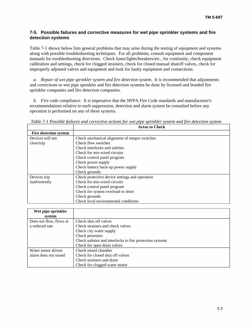
TM 5-697
7-7
7-5. Possible failures and corrective measures for wet pipe sprinkler systems and fire detection systems Table 7-1 shown below lists general problems that may arise during the testing of equipment and systems along with possible troubleshooting techniques. For all problems, consult equipment and component manuals for troubleshooting directions. Check fuses/lights/breakers/etc., for continuity, check equipment calibration and settings, check for clogged strainers, check for closed manual shutoff valves, check for improperly adjusted valves and equipment and look for faulty equipment and connections. a. Repair of wet pipe sprinkler system and fire detection system. It is recommended that adjustments and corrections to wet pipe sprinkler and fire detection systems be done by licensed and bonded fire sprinkler companies and fire detection companies. b. Fire code compliance. It is imperative that the NFPA Fire Code standards and manufacturer's recommendations relative to each suppression, detection and alarm system be consulted before any operation is performed on any of these systems. Table 7-1 Possible failures and corrective actions for wet pipe sprinkler system and fire detection system
Areas to Check Fire detection system
Devices will not close/trip
Check mechanical alignment of tamper switches Check flow switches Check interlocks and safeties Check for mis-wired circuits Check control panel program Check power supply Check battery back-up power supply Check grounds
Devices trip inadvertently
Check protective device settings and operation Check for mis-wired circuits Check control panel program Check for system overload or short Check grounds Check local environmental conditions
Wet pipe sprinkler
system
Does not flow, flows at a reduced rate
Check shut off valves Check strainers and check valves Check city water supply Check pressures Check safeties and interlocks to fire protection systems Check for open drain valves
Water motor driven alarm does not sound
Check retard chamber Check for closed shut off valves Check strainers and drain Check for clogged water motor

TM 5-697
8-1
CHAPTER 8
LIFTING AND MOVING DEVICES SUCH AS CRANES AND ELEVATORS ____________________________________________________________ 8-1. Description of lifting and moving devices There are many types, variations and capacities of lifting and moving devices to move objects and personnel. The devices addressed in this manual are primarily for moving objects; however freight elevators as well as personnel elevators can be used for moving personnel and objects. Included in this manual is a description of lifting and moving devises commonly encountered. a. Lifting devices. A description of typical cranes and other common lifting devices follows. (1) Bridge cranes are versatile and used in many applications. They consist of columns, rails, a bridge, trolley, one or more hoists, and for control, a pendant, cab and radio operator. (2) Jib cranes have a limited access area but are less expensive than other cranes. They consist of a column, swinging jib, trolley, hoist and pendant. (3) Gantry cranes are like mobile bridge cranes. They consist of a mobile gantry, trolley, hoist and pendant. (4) Frequently used non-powered lifting devices include hydraulic jacks, chain hoists, and rigging such as chains, wire ropes, slings, chokers, hooks and spreader bars. b. Elevators. Elevators consist of hydraulic ram lifts or motor driven cable lifts, a framed elevator shaft, an elevator car/enclosure with doors, telephone or intercom and push button controls. c. Lifting and moving devices. More information on requirements for design, maintenance, and testing of lifting and moving devices is to be found in the Occupational Health and Safety Administration, Standards (OSHA), Regulations Standards 29 CFR 1910 – Subpart N Material Handling and Storage, 1910.179 Overhead and gantry cranes, and 1910.184 Slings, plus 1926 – Subpart H Material Handling, Storage, Use, and Disposal, 1926.251 Rigging equipment for material handling, as well as 1926 – Subpart N Cranes and Derricks, 1926.550 Cranes, derricks, hoists, elevators, and conveyers, and 1926.552 Material hoists, personnel hoists, and elevators, and 1926.554 Overhead hoists. Additional information is supplied by the American Society of Mechanical Engineers (ASME) A 17.1 Safety Code for Elevators and Escalators, and B30 Cranes and Hoists. Further work has been done by the Sterling Elevator Consultants, LLC, Technical Paper, Elevator Safety Presentation 8-2. Operation of lifting and moving devices Operation of the devices addressed in this manual for moving objects and personnel follow. a. Lifting devices, operation. Following is a discussion of the operation of cranes and other common lifting devices typically encountered in facilities.

TM 5-697
8-2
(1) Bridge cranes travel on rails supported by columns. End stops are provided on the rails to limit crane travel. The crane columns may be separate or integral with the building steel. Foundations must be designed for the additional load of the crane. The crane consists of the bridge which spans the distance between the rails, a trolley which traverses the bridge and one or more hoists located on the trolley. End stops are provided on the bridge to limit travel of the trolley and limit switches are provided on the hoist to limit travel of a wire rope-mounted hook. Travel is normally controlled by a pendant with separate buttons for movement in the north, south, east, and west directions for the bridge and trolley and up and down for the hook on the hoist. If desired, motor speeds can be in steps or variably adjustable. Automatic brakes are provided on all traversing and lifting motors. In some cases the pendant is replaced with a radio controller, thereby eliminating the wire to the pendant. On larger cranes, controls can be provided in a bridge mounted operator cab. The lifting capacity of the crane must be clearly indicated and visible to the operator. Operators and personnel must not be under the lifted load at any time. (2) A jib crane includes a counter weight foundation mounted column with a swinging jib. Stops are provided on the column to limit the swing of the jib and also on the jib to limit trolley movement. The hoist is pendant controlled and with limit switches to safely limit hook travel. The trolley and jib can also be powered if desired. The lifting capacity of the crane must be clearly indicated and visible to the operator. Operators and personnel must not be under the lifted load at any time. (3) Gantry cranes consist of an inverted “U” shaped structure called a gantry. The structure is mobile and can straddle objects. A trolley traverses the upper cross member and supports a hoist. The gantry and trolley can be powered similar to a bridge crane. Stops and limit switches are provided as needed to limit movement of the gantry, trolley, and hoist hook. A pendant is used for control. The lifting capacity of the crane must be clearly indicated and visible to the operator. Operators and personnel must not be under the lifted load at any time. (4) Non-powered lifting devices and rigging include hydraulic jacks, chain hoists, chains, wire ropes, slings, chokers, hooks, shackles and spreader bars. The lifting capacity of lifting devices and rigging must be clearly labeled. Operators and personnel must not be under any lifted load at any time and must not ride on any hook or load. b. Elevators, operation. Elevators are used to lift freight and personnel. Lifting is accomplished by a hydraulic ram or cable drive with interlocks to control the acceleration, speed, stop positions, elevator doors, access doors and safety of the car. The elevator car/enclosure travels vertically in an elevator shaft with guide rails, and is provided with doors or a gate, roof hatch and push button controls. The doors/gate must be closed for the car to move. A mechanical safety brake is provided as a redundant safety to limit the travel of the car should all other mechanical and electrical interlocks and safeties experience a problem simultaneously. The lifting capacity of the elevator must be clearly indicated and visible to an operator. The car should be well lit, and be provided with an alarm, emergency lights and an emergency phone or intercom. Elevator entranceways should be clear of tripping and slipping hazards. Elevators are the only lifting and moving devices which may be used to lift personnel. 8-3. Pre-functional test plan and functional performance test plan for lifting and moving devices This manual assumes that individual components and packaged equipment have been tested by the manufacturer. As part of the commissioning effort each component should be checked for damage, deterioration and failures by a procedure using inspections and tests as defined by the specific equipment manufacturers. Equipment manuals from manufacturers identify the minimum required receipt inspections, handling and installation procedures, drawing and wiring verification, field inspection and
TM 5-697
8-3
installation checks, verification of removal of shipping braces, inspection of installation against drawings and nameplates, inspection of components for damage and cleanliness, inspection of insulators and grounding, inspection of anchorage and alignment, adjustment checks, mechanical operation and interlock checks, lubrication application and verification that local safety equipment is in place. a. Tests, lifting and moving devices. Tests and inspections as defined by the American Society of Mechanical Engineers (ASME) and as recommended by OSHA and the insuring agency should be done by licensed and bonded crane/elevator companies. Inspection checklists are provided to the facility manager and others as requested. These tests should form the basis of acceptance as required by the commissioning plan. Some pre-functional tests may be conducted to provide general knowledge of the system. These are outlined in figure 8-1, Example of a completed DA Form 7484-R, lifting and moving devices inspection checklist and figure 8-2, Example of a completed DA Form 7485-R, elevator inspection checklist. These are filled out to serve as an example of typical equipment conditions. For convenience, these checklists are included unpopulated at the end of this technical manual. b. Safety, lifting and moving devices. Many tests involve the use of high voltages, high currents, pressurized hydraulic systems and heavy loads. These can be dangerous to personnel and damaging to equipment. A procedure should be followed to insure adequate safety rules are instituted and practiced to prevent injury to personnel performing the tests and other personnel who might be in the local area. Personnel are permitted to ride in personnel elevators and freight elevators appropriately equipped and labeled. Personnel must not ride on any lifting hook c. Test equipment, lifting and moving devices. It is important that in any test program the proper equipment is used. The equipment should be calibrated, in good condition and used by qualified operators as required by a procedure. Any test equipment used for calibration shall have twice the accuracy of the equipment to be tested. All equipment should be operated in accordance with its instruction manual. A procedure defining installation inspection and moving and lifting equipment tests needs to be provided.

TM 5-697
8-4
Figure 8-1: Example: DA Form 7484-R
EXTERIOR OF EQUIPMENTCOMPLETENESS OF ASSEMBLYCONTROL SYSTEM DISPLAYSAFETY INTERLOCKSELECTRICAL/MECHANICAL INTERLOCKSINSTRUMENTS AND ALARMSPROPER GROUNDINGPROPER INSULATIONCABLE CHAIN CONDITION
AAAAARAAA
1
1. PLANT East Building
LIFTING AND MOVING DEVICES INSPECTION CHECKLISTFor use of this form, see TM 5-697; the proponent agency is COE.
SECTION A - CUSTOMER DATA
DA FORM 7484-R, DEC 2002 USAPA V1.00
2. LOCATION Washington, DC
3. JOB NUMBER EB03-104
4. EQUIPMENT Forklift
5. SYSTEM DESIGNATION FL 02
6. DATE (YYYYMMDD) 20030120
7. TEST EQUIPMENTWeight standard, Cable inspection gear, lift history
8. TESTED BY Roger Swanson
SECTION B - EQUIPMENT DATA9. CRANE MANUFACTURERGrove Telescopic Boom
10. MODEL NOY2933
11. SERIAL NO81704
13. CAPACITY22 Tons
14. HOIST MANUFACTURERMY-TE
16. SERIAL NO2375
SECTION C - VISUAL AND MECHANICAL INSPECTION
COND* NOTESCHECK POINT
EQUIPMENT IDENTIFICATIONEQUIPMENT CONDITIONCAPACITY IDENTIFICATIONLABELING AND TAGGINGEND AND/OR SWING STOPS IN PLACEACCESSANCHORAGECOMPARISON TO DRAWINGSALIGNMENT
AAAAAAA
NANA
COND* NOTESCHECK POINT
SECTION D - CALIBRATION AND SET POINT
*CONDITION: A=ACCEPTABLE; R=NEEDS REPAIR, REPLACEMENT OR ADJUSTMENT; C=CORRECTED; NA=NOT APPLICABLE
22. NOTES1. G lass cracked on hydraulic pressure gauge.
19.
15. MODEL NO10-22
18. CAPACITY750 lbs
LIMIT SWITCHESSECTION E - LIFTING AND MOVING DEVICES EQUIPMENT TESTS
20.
Check for proper adjustment and operation
DESCRIPTION NOTES
LOAD TESTTEST ALL BRAKESSAFETIES TESTALARMSCABLE/HOOK INSPECTIONOPERATIONAL TEST
21.NOTESPASS FAIL COMMENTS
12. LOCATIONBuilding 4217. LOCATIONBuilding 42

TM 5-697
8-5
Figure 8-2: Example: DA Form 7485-R
ELEVATOR INSPECTION CHECKLISTFor use of this form, see TM 5-697; the proponent agency is COE.
DA FORM 7485-R, DEC 2002 USAPA V1.00
*CONDITION: A=ACCEPTABLE; R=NEEDS REPAIR, REPLACEMENT OR ADJUSTMENT; C=CORRECTED; NA=NOT APPLICABLE
EXTERIOR OF EQUIPMENTCOMPLETENESS OF ASSEMBLYCONTROL SYSTEM DISPLAYSAFETY INTERLOCKSELECTRICAL/MECHANICAL INTERLOCKSINSTRUMENTS AND ALARMSPROPER GROUNDINGPROPER INSULATIONELEVATOR DOORSENTRANCE WAYCABLE CHAIN CONDITION
AAAAAAAAAAA
1
1. PLANT East Building
SECTION A - CUSTOMER DATA2. LOCATION Washington, DC
3. JOB NUMBER EB03-105
4. EQUIPMENT 5. SYSTEM DESIGNATION Otis 23
6. DATE (YYYYMMDD) 20030121
7. TEST EQUIPMENTVoltmeter, P ressure tester , Hand tools for visual as required by type elevator
8. TESTED BY David Ryan
SECTION B - EQUIPMENT DATA9. ELEVATOR MANUFACTUREROtis
10. MODEL NOHydraulic
11. SERIAL NO1290
13. CAPACITY2000 lbs
14. DRIVE MANUFACTUREROtis
16. SERIAL NO3241656
SECTION C - VISUAL AND MECHANICAL INSPECTION
COND* NOTESCHECK POINT
EQUIPMENT IDENTIFICATIONEQUIPMENT CONDITIONCAPACITY IDENTIFICATIONLABELING AND TAGGINGALARM, TELEPHONE, INTERCOMACCESSANCHORAGECOMPARISON TO DRAWINGSALIGNMENTHYDRAULIC LEAKS
AAAAAAAAAA
COND* NOTESCHECK POINT
SECTION D - CALIBRATION AND SET POINT
22. NOTES1. Doors worked smoothly
19.
15. MODEL NOOtis
18. CAPACITY4000 lbs
HYDRAULIC PRESSUREDOOR POSITION
SECTION E - LIFTING AND MOVING DEVICES EQUIPMENT TESTS
20.
Note pressure measurements and extreme positions of operationNote ease of operation and opened and closed positions of doors
DESCRIPTION NOTES
LOAD TESTTEST ALL BRAKESSAFETIES TESTALARMSOPERATIONAL TEST
21. NOTESPASS FAIL COMMENTS
12. LOCATIONFront entrance17. LOCATIONRooftop
Load elevator to indicated rated loadEmergency stop

TM 5-697
8-6
8-4. Possible failures and corrective measures for lifting and moving devices Table 8-1 below lists general problems that may arise during the testing of equipment and systems along with possible troubleshooting techniques. For all problems, consult equipment and component manuals for troubleshooting directions. Check fuses/lights/breakers/etc., for continuity, check equipment calibration and settings, check for improperly adjusted equipment and limit/proximity switches and look for faulty equipment and connections.
Table 8-1, Possible failures and corrective actions for lifting and moving devices
Areas to Check Bridge cranes, jib cranes, gantry cranes
Hoist, trolley, bridge, gantry will not actuate/move
Check key lockout switch Check control buttons/levers/joy-stick actuation and contacts Check radio signal if applicable Check mechanical alignment of limit/proximity switches Check interlocks and safeties Check for mis-wired circuits Check control panel program Check power supply Check grounds
Check protective device settings and operation Check for mis-wired circuits Check control panel program Check for system overload or short Check grounds
Elevator Does not move Check door/gate interlocks
Check control buttons actuation and contacts Check mechanical alignment of limit/proximity switches Check interlocks and safeties Check for miss-wired circuits Check control panel program Check power supply Check grounds
Doors do not open Check car stop position and limit/proximity switches Check car door / access door interlock Check safeties and interlocks
Car stops above or below floor level
Check car stop position and limit/proximity switches

TM 5-697
9-1
CHAPTER 9
HIGH ALTITUDE ELECTROMAGNETIC PULSE (HEMP) EQUIPMENT AND CONTROLS
____________________________________________________________ 9-1. Description of HEMP protection for mechanical systems HEMPs, generated from the explosion of a nuclear bomb at high altitude, are of the most concern to command, control, communications, computers, intelligence, surveillance and reconnaissance (C4ISR) facilities because they cover such a large area. The burst from the bomb may cause large currents or potential differences to be induced in many types of conductors. This energy can couple to wires or any conductor above or below ground and induce signals which cause malfunctioning of sensitive equipment or induce energy of significant magnitude to damage and destroy sensitive equipment used in C4ISR facilities. For these reasons HEMP protection must be employed. HEMP protection involves shielding, bonding and grounding. Shielding for the facility is usually provided by sheets of steel welded together to enclose the entire facility. Continuous welding provides a continuous bond and a uniform shield around the facility. Grounding of the shield is accomplished through the earth electrode system in a grounding plan with calculated number, size, type and ground locations. There are essentially two mechanical items which require HEMP protection, ports and penetrations. a. Ventilation ports. In C4ISR facilities ventilation ports are needed to provide fresh air and exhaust relief air from the facility. HEMP protection is provided by using honeycomb ducts at the port or a screen bonded over the port. b. Pipe and ventilating duct penetrations. Pipe and ventilating ducts penetrating facility shielding should be minimized. Where penetrations are needed HEMP protection is provided by minimizing the number of penetrations, maintaining them at a common location, and bonding them to the shield wall. Bonding is accomplished preferably by continuously welding, brazing, hard soldering, or other fused metal process. Collets or clamps can also be used. Bonding the circumference of the pipe or duct to the shield at their entry point is needed. Another method is to use a dielectric section of pipe or duct at the shield to prevent energy inducted in the external metallic pipe and ducts from being conducted through the shield. c. HEMP protection for mechanical systems. More information on HEMP sources and effects, and HEMP protection design, maintenance, and testing for ventilating ports, and pipe and ventilating duct penetrations can be found in the American Society of Mechanical Engineers (ASME) B 31.3, Process piping, the Department of the Army: TM 5-692-1 Maintenance of Mechanical and Electrical Equipment at C4ISR Facilities, Recommended Maintenance Practices, chapter 27, TM 5-692-2 Maintenance of Mechanical and Electrical Equipment at C4ISR Facilities, System Design Features, chapter 27, and TM 5-690, chapter 5 9-2. Operation of HEMP protection for mechanical systems

TM 5-697
9-2
As HEMP protection systems are passive, their degradation has little effect on normal facility operation. For mechanical ports and penetrations there are no moving parts. Therefore there are no operating requirements. Once properly designed and installed only the effectiveness of the HEMP protection system can be measured and is required to be checked as part of the hardness maintenance and hardened surveillance programs. 9-3. Pre-functional test plan and functional performance test plan for HEMP protection of mechanical systems As part of a commissioning procedure each component should be checked for damage, deterioration, failures, missing parts, openings, dirt, corrosion, weld integrity, dust, foreign debris, bonded electrical resistance, wave radiated fields and shielded enclosure leaks. a. Safety, HEMP protection of mechanical systems. Many tests on equipment take place around high voltages, high currents and rotating or moving equipment. These can be dangerous to personnel and damaging to equipment. A procedure should be followed to insure adequate safety rules are instituted and practiced to prevent injury to personnel performing the tests and other personnel who might be in the local area. b. Test equipment, HEMP protection of mechanical systems. It is important that in any test program the proper equipment is used. The equipment should be calibrated, in good condition and used by qualified operators as required by a procedure. Any test equipment used for calibration shall have twice the accuracy of the equipment to be tested. All equipment should be operated in accordance with its instruction manual. A procedure defining installation inspection and a system test needs to be provided. c. Tests, HEMP protection of mechanical systems. An inspection checklist for HEMP protection of mechanical systems is presented in figure 9-1, Example of a completed DA Form 7486-R, HEMP protection of mechanical systems inspection checklist. It is filled out to serve as an example of typical equipment conditions. For convenience, this checklist is included unpopulated at the end of this technical manual. 9-4. Possible failures and corrective measures for HEMP protection of mechanical systems Table 9-1 on page 9-4 lists general problems that may arise during the testing of equipment and systems along with possible troubleshooting techniques. For all problems, consult equipment and component manuals for troubleshooting directions. Check for continuity, check test equipment calibration and settings and look for faulty equipment and connections.

TM 5-697
9-3
Figure 9-1: Example: DA Form 7486-R
IDENTIFICATIONCOMPLETENESS OF INSTALLATIONELECTRICAL/MECHANICAL INTERLOCKSPROPER SHIELDINGPROPER BONDINGPROPER GROUNDINGPROPER INSULATION
AAARAAA
1
1. PLANT South Building
HIGH ALTITUDE ELECTROMAGNETIC PULSE (HEMP) PROTECTIONOF MECHANICAL SYSTEM INSPECTION CHECKLIST
For use of this form, see TM 5-697; the proponent agency is COE.
SECTION A - CUSTOMER DATA
DA FORM 7486-R, DEC 2002 USAPA V1.00
2. LOCATION Washington, DC
3. JOB NUMBER SB03-101
4. EQUIPMENT 5. SYSTEM DESIGNATION HEMP 02
6. DATE (YYYYMMDD) 20030122
7. TEST EQUIPMENTASTM 1851-02 Std suggested testing practice with calibrated equipment
8. TESTED BY David Ryan
SECTION B - EQUIPMENT DATA9. MANUFACTURER 10. MODEL NO 11. SERIAL NO 12. TYPE
SECTION C - VISUAL AND MECHANICAL INSPECTION
COND* NOTESCHECK POINT
LABELING AND TAGGINGSAFETY INTERLOCKSCOMPARISON TO DRAWINGSWELD INTEGRITYDIRT, CORROSION, DUST, DEBRISDAMAGE
AAAAAR 2
COND* NOTESCHECK POINT
SECTION D - CALIBRATION
*CONDITION: A=ACCEPTABLE; R=NEEDS REPAIR, REPLACEMENT OR ADJUSTMENT; C=CORRECTED; NA=NOT APPLICABLE
16. NOTES1. Break in the door seal2. Damaged door3. This test method is for use in the following frequency ranges: 140 - 160 kHz, 14 - 16 M Hz, 300 - 500 M Hz, 900 - 1000 M Hzand 8.5 - 10.5 GHz. Additional measurements in the range of 10 kHz to GHz may be performed. For specific applications, thefrequency range may be extended from 50 Hz to 40 GHz. This provides guidance on selecting measurement frequencies.4. Record resonnance reaction at each test level as indicated in section D .5. Record variations depending upon ambient temperature and ambient pressure.
13.
TEST INSTRUMENTSSECTION E - SYSTEM TESTS
14.
See frequency ranges in note 3 below
DESCRIPTION
3
NOTES
BONDED ELECTRICAL RESISTANCE TESTWAVE RADIATED FIELD TESTSHIELDED ENCLOSURE LEAK TEST
15.NOTESOPERATING MODES TEMPERATURES PRESSURES FLOWS LEVELS
StandbyOperate/TransmitOperate/Transmit
AmbientAmbientAmbient
AmbientAmbientAmbient
NANANA
ResistanceTestTest
544

TM 5-697
9-4
Table 9-1. Possible failures and corrective actions for HEMP protection of mechanical systems
Areas to Check Ventilation Ports HEMP protection is breached
Check bonding, shielding, and grounding Check for mis-wired circuits Check weld impedance Check screen covering the port opening
Pipe and ventilating duct penetrations
HEMP protection is breached
Check bonding, shielding, and grounding Check for mis-wired circuits Check for continuous welds of pipe and duct, to shielding Check weld impedance

TM 5-697
10-1
CHAPTER 10
WATER AND SEWAGE TREATMENT SYSTEMS ____________________________________________________________ 10-1. Description of water and sewage treatment systems A description of a typical potable water supply, process water supply and small and large scale sewage treatment systems follows. Additional information on water and sewage treatment equipment and systems is presented in paragraph 10-3, General water and sewage treatment equipment description and operation. a. Facility potable water and process water supply. The water supply to a facility normally meets potable (drinking) water standards. The water supply is separated from facility potable water with a back flow preventer and from the facility process water with a second back flow preventer. (1) A typical water system is shown in figure 10-1, Schematic of a typical potable and process water system. The system consists of the water supply, isolation valves, strainer, back flow preventers, drain, pressure regulators and gages.
BFP
BFP
WATER SUPPLY
DRAIN
DRAINREGULATOR
REGULATOR
PROCESS WATER
POTABLE WATER
Figure 10-1. Schematic of a potable and process water system
(2) Water treatment is needed for process water used in chilled water, heating water and steam and cooling tower systems. The type of treatment depends on the quality of the water supply and the types of equipment in service. The typical systems presented elsewhere in this technical manual include a chilled water system and a heating water system. Process water is used for fill and makeup water on both of these systems. (3) Process water for closed loop chilled and heating water systems needs to be treated to control corrosion, scale formation, growth of biological agents and pH. In the closed cooling water system, treatment of the water for dissolved oxygen (O2) to prevent corrosion is needed during filling or when opened for maintenance. Scale is usually not a problem in chilled water systems. In the closed heating water system, monitoring is needed for corrosion from dissolved O2 and scale formation from precipitation of minerals in the water. A typical process water treatment system is presented in figure 10-

TM 5-697
10-2
2, Process water treatment schematic. Process water treatment consists of a pot feeder, feeder fill point, isolation valves and chemicals.
FEEDERFILL POINT
VENT
POT FEEDER ASSEMBLY
DRAIN
STREAM TO BE TREATED
Figure 10-2. Schematic of a process water treatment system
b. Sewage treatment systems. Sanitary sewage is any liquid waste containing animal matter, vegetable matter and/or certain chemicals in suspension or solution. It excludes storm, surface and ground water. Sewage treatment removes impurities so that the remaining water can be safely returned to the natural water cycle. (1) Sewage treatment for small facilities in remote or rural areas involves a septic tank and drain field. Refer to figure 10-3 for a cross section of a septic tank. (2) Sewage treatment for larger facilities and facility complexes can consist of source, preliminary, primary, secondary and advanced treatment operations. (3) Treatment at the source of wastewater to render it safe for sanitary sewage treatment can vary greatly depending on the chemical, manufacturing, or operational processes which produce the waste water. In the sewage treatment facility, preliminary treatment is provided to protect downstream equipment and minimize operational problems. Preliminary treatment includes neutralization, screening, grit removal and temperature adjustment. Primary treatment at times requires chemical addition but mainly involves physical treatment of the waste to remove settleable and floatable materials. In primary treatment, settling tanks are used for solids removal. (4) Secondary wastewater treatment relies on naturally occurring microorganisms acting to break down organic material and purify the liquid. Secondary treatment brings air and therefore O2 in contact with sewage to encourage micro-organisms to grow, thereby removing substantial quantities of dissolved organics and colloidal materials. This results in purified water. The process or combination of processes

TM 5-697
10-3
used in advanced sewage treatment systems are dictated by effluent quality standards which exceed established secondary treatment standards.
BAFFLE
ACCESS COVER
SCUM
SLUDGE
EFFLUENT
Figure 10-3. A cross section of a septic tank (5) The typical sanitary sewage waste treatment system selected for discussion in this manual is the trickling filter process shown in figure 10-4, Sewage trickling filter process. The system consists of a preliminary treatment system, primary sedimentation tank, high rate trickling filter, secondary sedimentation tank, disinfection unit, sludge thickener, sludge dewatering tank and sludge digestion unit.
RAWWASTEWATER
PRELIMINARYTREATMENT
HIGH RATETRICKLING FILTER
RECIRCULATED FLOW
SECONDARYSEDIMENTATION DISINFECTION
TO STREAM
WA
ST
E S
LU
DG
E
RETURN ACTIVATED SLUDGE
SLUDGE UNDERDRAIN
SUPERNATANT
SLUDGEDIGESTION
SLUDGETHICKENER
EFFLUENT
SLUDGEDEWATERING
TO FINALDISPOSAL
PRIMARYSEDIMENTATION
Figure 10-4. Sewage trickling filter process
c. Water and sewage treatment systems. More information on design, maintenance and testing of water and sewage treatment systems is found in the Management of Industrial Pollutants by Anaerobic Processes by Alan W. Obayashi and Joseph M. Gorgan, Rensselaer Polytechnic Institute, May 1984, the

TM 5-697
10-4
Department of the Army: TM 5-692-1 Maintenance of Mechanical and Electrical Equipment at Command, Control, Communications, Computers, Intelligence, Surveillance, and Reconnaissance (C4ISR) Facilities, Recommended Maintenance Practices, chapters 13 and 18 and TM 5-692-2 Maintenance of Mechanical and Electrical Equipment at C4ISR Facilities, System Design Features, chapters 13 and 18. 10-2. Operation of water and sewage treatment systems A discussion on the operation of the typical potable water supply, process water supply and small and large scale sewage treatment systems follows. a. Potable water system, operation. For both the facility potable water and process water, the water supply to the facility flows through a shutoff valve, strainer, isolation valves, back flow preventer and pressure regulator. The strainer removes particles from the water and can be back flushed for cleaning. Valves are located up and down stream of the pressure regulator and a bypass installed as needed for change out of the regulator. The back flow preventer incorporates a drain to bleed off water which back flows as a result of back pressure and a malfunction with one of the check valves contained within the unit. This protects the water supply from contamination by preventing facility potable and process water from flowing backward into the water supply. b. Process water treatment system, operation. An analysis of the water supply and process water in the chilled and heating water systems determines the type of treatment and chemicals needed. (1) To treat process water, chemicals are fed into a pot feeder and introduced into the process water system by manipulation of isolation valves which allow process water to flow through the pot, mix with the chemicals and flow back into the system. (2) Manufactured chemical products contain combinations of proprietary chemicals and different forms of generic chemicals to enhance water treatment performance. Water treatment chemical suppliers tailor chemical treatment needs to local water conditions and establish procedures for safe chemical storage and handling. Some basic chemicals include: sodium hydroxide (NaOH) which increases alkalinity, chelants (EDTA, NTA) which control scaling and sodium sulfate (Na2SO3) and Hydrazine (N2H2) which prevent O2 corrosion. More chemical selection information is presented in Department of the Army: TM 5-692-2 Maintenance of Mechanical and Electrical Equipment at C4ISR Facilities, System Design Features, Chapter 13. c. Small scale sewage treatment system, operation. In a septic system, sewage from a small facility flows into an underground septic tank. Solids settle out as sludge on the bottom of the tank and are anaerobically digested. Gases produced by digestion are vented back through the plumbing of the facilities through vent stacks in the roof. A scum forms on the top and an almost clear effluent develops in the middle as solids settle and separate. An inlet baffle aids the separation of suspended solids and provides minimal agitation of the sludge for anaerobic digestion. An outlet baffle prevents scum from entering the outlet pipe and clogging the drain field tile. The outlet pipe is connected to a drain field which consists of a perforated, usually plastic pipe or tile, which may run several hundred feet underground depending on the ability of the ground to percolate water. The sloped drain tile is embedded in layers of sand and rock to facilitate percolation and is located below the frost line. Construction of septic systems is monitored by local authorities to insure proper construction and therefore proper operation of these passive sewage treatment systems.

TM 5-697
10-5
d. Large scale sewage treatment system, operation. In the larger capacity typical sanitary sewage trickling filter process, the preliminary treatment system utilizes bar screens to remove wood, plastic, rags, paper and other large solid objects from sewage influent. Sand and grit which can damage pumps are also removed. A primary sedimentation tank is next in the process. It allows sufficient settling time to permit approximately 50 to 70 percent of the remaining solids to settle out and removes 30 to 40 percent of the biochemical O2 demand (BOD). (1) Next a high rate trickling or percolating filter provides an environment encouraging aerobic microorganisms to feed on bacteria in the sewage. Sewage is pumped through spray bars and is trickled over stones in an open air tank. The trickling and the drops falling from one stone to the next provide exposure of the liquid to air, and the rocks provide a surface for microorganisms to live on. These conditions promote aerobic microorganism growth and consumption of sewage bacteria thus removing the remaining BOD and suspended solids. (2) A secondary sedimentation tank provides residence time to separate biological sludge from the purified water exiting the trickling filter. To destroy pathogenic organisms, the water is disinfected with hypochlorate, ozone (O3), or ultraviolet (UV) light and discharged to a stream or natural body of water. Periodic unannounced sampling by local authorities insures that the discharge remains within safe and legal limits. (3) Sludge from the secondary sedimentation tank consists of 90 percent organic matter and 2 to 4 percent solids and is pumped back to the primary sedimentation tank. (4) Sludge from the primary sedimentation tank is mostly water containing organic matter. It is pumped to a sludge thickener. In the thickener, sludge volume is reduced to half and effluent is recycled to the primary sedimentation tank. The sludge is then pumped to the digestion unit. In the digester, organic matter in the sludge is decomposed by anaerobic bacteria which further breaks down the sludge rendering it inert and eliminating health concerns. Anaerobic bacteria does not require free O2 to decompose organic matter. It does allow separation of solids and water, reduces sludge volume, increases sludge density and produces combustible methane gas in combination with other gases. (5) Sludge produced in the digester consisting of relatively stable inert organic and inorganic compounds continues on to a sludge dewatering system and then disposal. It can also be sold as soil conditioner. The supernatant liquids (usually a clear liquid overlying material deposited by settling or precipitation) produced are returned to the primary sedimentation tank and the gases are cleaned and stored. The combustible gases can be used to generate heat for local processes or sold as combustible fuel. (6) Monitoring of sewage flow and effluent discharge is required by the Environmental Protection Agency (EPA) when National Pollution Discharge Elimination System (NPDES) compliance is required as part of the discharge permit. 10-3. General water and sewage treatment equipment description and operation

TM 5-697
10-6
There are many ways to treat water to be used in industrial processes and for human consumption. In addition there are also many ways to treat sanitary sewage so that it can be safely returned to the natural water cycle. Following is a discussion of some of the equipment and systems available to treat water and sewage. a. Water disinfection. Chlorination is the traditional disinfectant used in municipal water treatment. It is a strong oxidizing agent, inexpensive, reliable, easy to use and monitor and safe when handled properly. Chlorination with chlorine gas is the oldest method of continuous disinfection method used in public water supplies. It was initially introduced in 1904. Disinfection by chlorination has been studied extensively, and is the standard by which other disinfection procedures are judged. Disinfecting forms of chlorine are hypochlorites, chlorine dioxide and products of chlorine-ammonia reactions. (1) Simple diffuser systems are adequate for distributing chlorine into water, with warming of the supply tank required for high feeding rates. Hazards of working with chlorine include explosions of pressure vessels (especially if corrosion weakens them) and violent reactions when chlorine comes in contact with oxidizable substances. (2) Chlorination is the final step for most wastewater treatment plants. In addition to disinfection of the effluent, BOD is reduced because reaction with chlorine substitutes for reaction with O2. The residual chlorine discourages iron bacteria that form slimes in effluent conduits and insects are also killed. Most smelly compounds in treatment plant effluents are easily reacted with chlorine, usually to odorless products. Unfortunately, the products of chlorination may be hazardous and some are known carcinogens. Concentrations in the environment may be much higher than in the effluents because microorganisms or other life forms ingest and store chlorinated organic compounds. (3) O3 (ozone) is also used for disinfection. O3 is a colorless gas at room temperature, and has a peculiar, pungent odor. O3 is unstable and cannot be produced and transported. It is generated at its point of use by an electrical corona discharge or UV irradiation of dry air or O2. O3 can be injected or diffused into the water supply stream. (4) Advantages of O3 over chlorine include the following. (a) Safety problems of chlorine storage, handling, and transportation are eliminated. O3 is produced on-site. (b) O3 destroys both bacteria and viruses, while chlorine is not very effective against viruses. (c) O3 has shorter treatment times (one to ten minutes for O3 versus 30 to 45 minutes for chlorine). (d) There are lesser pH and temperature effects with O3. (e) High dissolved O2 concentration from ozonation improves receiving stream quality. (f) No toxicity to aquatic life has been found in studies of O3 disinfection. (g) No buildup of bioaccumulatable residuals has been observed in O3-treated effluents. (h) There is no increase in total dissolved solids in O3-treated water.

TM 5-697
10-7
(i) Wastewater quality improvements such as turbidity reduction and effluent decolorization accompany O3 treatment. (5) The disadvantages in using O3 to treat water include the following. (a) It is costly to produce O3, for both capital equipment and operating power requirements. (b) O3 is toxic. The Public Health Department has set the maximum safe working concentration at 0.1 ppm. (c) There is great difficulty in accurately determining the concentration of O3 in water. The best method thus far has an error of ± 1 percent . (6) UV light is another method of disinfection. UV light used for disinfection occupies the spectral range from just below visible light to soft X-rays. UV radiation at about the center of the range has been found to kill or deactivate many pathogens. UV treatment does not necessarily kill the target organism, instead the radiation alters cell DNA so that the organism is sterilized. This serves to inactivate the pathogen so that it cannot proliferate and cause disease. (7) Bacteria are the easiest group to treat and differ the least in amount of radiation required. Viruses are most resistant and variable. Cysts and worms are unaffected by UV light so if present they must be treated by another procedure. (8) UV treatment adds nothing to the water and does not require the addition of treatment materials as long as the system used is maintained in good operating condition. Extensive contact time is not required in this process making it a time efficient treatment option. (9) The major disadvantage is that there is no residual for treatment beyond the device. If contaminants enter after treatment, another disinfection method such as chlorination must be used to sanitize the system and treat the water. Some pathogens deactivated by UV light may be reactivated when exposed to O2. UV light is easily absorbed by solids, including particulate matter in the water or deposits on the lamp surface. As a consequence, UV light treatment should only be attempted on clear water. Water systems which store potable water for long periods may require disinfection to control the growth of biological contaminants and algae. Water samples taken are tested to determine the amount and strength of hypochlorite solution treatment needed. Disinfection can be accomplished by directly injecting hypochlorite into the water, adding hypochlorite into a recirculating side stream or a combination of both. b. Process water treatment. Open process water systems in cooling towers are constantly exposed to air and with constant evaporation, raw water is continually being introduced. As a result the cooling water can contain large amounts of dissolved O2 and the concentration of impurities/dissolved solids increases significantly over time. Frequent water quality monitoring is needed to control corrosion, scale formation, growth of biological agents and pH. The dissolved solids are usually removed with controlled periodic blowdown of the system. Treatment methods can be as simple as an operator adding slugs of chemicals to a pot/tank or can be as sophisticated as using a continuous analyzer to automatically control operation of chemical metering pumps. The pumps inject chemicals into the water stream to maintain uniform water quality. The analyzer reads output signals from instruments/probes in the process water stream to measure pH, conductivity, dissolved solids concentration, raw water flow and corrosion. The analyzer signals metering pumps to inject appropriate quantities of chemicals in the water to adjust

TM 5-697
10-8
quality. In less sophisticated systems where periodic sampling has indicated changes to water quality are slow and fairly constant, fixed doses of chemicals can be injected by metering pumps run on timers. (1) Steam boilers above 600 psig may have problems with water foaming and caustic embrittlement of metal components. For these boilers water quality is typically accomplished by a combination of chemical treatment, deaeration and blowdown. (2) Deaeration is the removal of dissolved gaseous carbon dioxide (CO2) and O2 from supply water. These gases greatly increase corrosivity and when heated in boiler systems combine with water to form carbonic acid. Removal of O2, CO2, and other non-condensable gases from boiler feedwater is vital to boiler equipment longevity as well as safety of operation. Carbonic acid corrodes metal, reducing the life of equipment and piping. It also dissolves iron which when returned to the boiler precipitates and causes scaling on the boiler tubes contributing to reduced life and also increased energy consumption to achieve heat transfer. (3) Mechanical deaeration is typically utilized prior to the addition of chemical O2 scavengers. In mechanical deaeration boiler feedwater is heated with steam. This scrubbing action releases O2 and CO2 gases which are then vented. Trace O2 is removed with a chemical O2 scavenger such as Na2SO3 or N2O2. Free CO2 can be removed by deaeration, but this process only removes small amounts of combined CO2. The majority of the combined CO2 is removed in the steam, subsequently dissolving in the condensate and causing corrosion problems. These problems can be controlled through the use of volatile neutralizing amines or filming amines. (4) Water softeners are used to remove dissolved solids for reduced foaming and scale formation. Water softeners contain a plastic bead or zeolite in a column. The zeolite is saturated with sodium chloride, salt. When water is passed through the column, the calcium and magnesium in the water is replaced with sodium. The water is said to be soft at this point. The sodium compounds do not settle out and cause scale or other problems of the hard water. The column is regenerated with a strong salt/brine solution and backflushed. (5) Ion exchange units have a cation exchange column to remove metals and hardness and an anion exchange column to control alkalinity and reduce corrosion, embrittlement, hard scale and foaming. Each exchange column uses a treated resin bed to collect contaminants through a chemical exchange process. When the beds become saturated they are back washed, treated with an electrolyte, rinsed and placed back in service. Duplex columns are used to achieve continuous operation. c. Water treatment piping. For water treatment systems common pipe, valve, and pump materials include cast and forged carbon and stainless steel. Low pressure systems can use plastic materials such as polyvinyl chloride (PVC). d. Sewage treatment processes. Other methods for treating sanitary sewage are discussed in the following paragraphs. (1) The plug flow activated sludge process is another process used to treat sanitary sewage. This process meets secondary treatment effluent limits. The process includes a bar screen as preliminary treatment and a comminutor (a device which reduces material to minute particles, pulverizer), a grit chamber and oil and grease removal units. The primary aerated wastewater and acclimated micro-organisms are aerated in a tank. Flocculent activated sludge solids are separated from the wastewater in a secondary clarifier. The clarified wastewater flows forward for further treatment or discharge. A portion

TM 5-697
10-9
of the clarifier sludge is returned to the aeration tank for mixing with the primary-treated influent to the basin and the remaining sludge is pumped to the sludge handling portion of the treatment plant. (2) Another sanitary treatment process is the stabilization or oxidation pond process. This process uses a relatively shallow body of wastewater in an earthen basin to treat a variety of wastewater and functions under a range of weather conditions. The ponds can be aerobic or layered with aerobic and anaerobic layers. They can be used in combination with other treatment processes. Their operational and maintenance requirements are minimal. (3) Advanced wastewater treatment achieves pollutant reductions by methods other than sedimentation, activated sludge and trickling filters used in conventional treatment. Advanced treatment employs a number of different unit operations, including ponds, post-aeration, micro-straining, various types of filtration, carbon adsorption, membrane solids separation, land application, biomass growth, soil biota growth, nitrification/de-nitrification and other treatment processes. Phosphorus and nitrogen removal processes can consist of additional treatment ponds; post-aeration through advanced methods; and the addition of minerals, lime, metal salts and polymers for removal through flocculation (mass formed by the aggregation of a number of fine suspended particles) or precipitation. e. Sewage treatment ancillary equipment. Following is a description of some of the types of ancillary equipment needed for the treatment of sewage. (1) Sewage flow measurement is needed to assure compliance with permits and to evaluate and adjust treatment processes. Flow can be measured with weirs, Parshall flumes and magnetic and ultrasonic flow meters. (2) Sewage sampling is needed to assure compliance with permits and to evaluate and adjust treatment processes. Proportional flow, composite and grab-sample collection sampling is done at several locations in the process for this purpose. (3) Monitoring equipment is used to indicate and/or record flow quantities and pressure, temperature, liquid levels, velocities, dissolved O2, biochemical O2 demand, total suspended solids, ammonia, nitrate and pH. (4) Sewage lift stations and sump pumps are needed where there is not enough elevation drop available for the sewage to flow by gravity all the way to the septic tank or treatment plant. Lift stations provide pits or sumps with submerged centrifugal motor driven pumps or compressed air driven ejector pumps. 10-4. Pre-functional test plan and functional performance test plan for water and sewage treatment systems This manual assumes that individual components and packaged equipment have been tested by the manufacturer. As part of the commissioning effort each component should be checked for damage, deterioration and failures by a procedure using inspections and tests as defined by the specific equipment manufacturers. Equipment manuals from manufacturers identify the minimum required receipt inspections, handling and installation procedures, drawing and wiring verification, field inspection and installation checks, verification of removal of shipping braces, inspection of installation against drawings and nameplates, inspection of components for damage and cleanliness, inspection of insulators and grounding, inspection of anchorage and alignment, adjustment checks, mechanical operation and interlock checks, lubrication application and verification that local safety equipment is in place.

TM 5-697
10-10
a. Chemical selection verification. As part of the commissioning effort proper selection and dose quantity of chemicals for treatment of water and sewage need to be verified. A procedure must be followed to insure proper chemical treatment and water quality. b. Safety, water and sewage treatment systems. Many tests on equipment involve the use of chemicals, combustible gases, high voltages, high currents, pressurized water and rotating or moving equipment. These conditions can be dangerous to personnel and damaging to equipment. A procedure must be followed to insure adequate safety rules are instituted and practiced to prevent explosion and/or injury to personnel performing the tests and other personnel who might be in the local area. Sanitary manholes contain harmful gases and are considered confined space. Confined space entry safety procedures must be followed and adequate ventilation provided before entering a manhole. c. Test equipment, water and sewage treatment systems. It is important that in any test program the proper equipment is used. The equipment should be calibrated, in good condition and used by qualified operators as required by a procedure. Any test equipment used for calibration shall have twice the accuracy of the equipment to be tested. All equipment should be operated in accordance with its instruction manual. A procedure defining installation inspection and a system test needs to be provided. d. Inspection checklists for water and sewage treatment systems. Inspection checklists for the typical water and sewage treatment systems are presented in figure 10-5, Example of a completed DA Form 7487-R, Water supply and treatment system inspection checklist and figure 10-6, Example of a completed DA Form 7488-R, Sewage treatment systems inspection checklist. These are filled out to serve examples of typical equipment conditions. For convenience, this checklist is included unpopulated at the end of this technical manual. 10-5. Possible failures and corrective measures for water and sewage treatment systems Table 10-1 on page 10-13 lists general problems that may arise during the testing of equipment and systems along with possible troubleshooting techniques. For all problems, consult equipment and component manuals for troubleshooting directions. Check fuses/lights/breakers/etc., for continuity, check equipment calibration and settings, check for clogged filters, strainers and lines, check for closed manual shut off valves, check for improperly adjusted valves and equipment and look for faulty equipment and connections.

TM 5-697
10-11
Figure 10-5: Example: DA Form 7487-R
WATER SUPPLY AND TREATMENT SYSTEM INSPECTION CHECKLISTFor use of this form, see TM 5-697; the proponent agency is COE.
DA FORM 7487-R, DEC 2002 USAPA V1.00
*CONDITION: A=ACCEPTABLE; R=NEEDS REPAIR, REPLACEMENT OR ADJUSTMENT; C=CORRECTED; NA=NOT APPLICABLE
EXTERIOR OF EQUIPMENTCOMPLETENESS OF ASSEMBLYINTERLOCKSINSTRUMENTSPROPER GROUNDINGPROPER INSULATIONTIGHTNESS OF BOLTED CONNECTIONSLEAKS
AAAAAAAA
1. PLANT Building 42
SECTION A - CUSTOMER DATA2. LOCATION Washington, D C
3. JOB NUMBER B42-105
4. EQUIPMENT 5. SYSTEM DESIGNATION WPT 22
6. DATE (YYYYMMDD) 20030117
7. TEST EQUIPMENTWater test kit 22, P ro-M aster equipment
8. TESTED BY Charles G ray
SECTION B - EQUIPMENT DATA9. BACK FLOW PREVENTER MANUFACTURERP V C
10. MODEL NOP V -4300
11. SERIAL NO543622
12. FLOW RATING4 inch pipe
13. PRESSURE REGULATORP V C
15. SERIAL NO653466
SECTION C - VISUAL AND MECHANICAL INSPECTION
COND* NOTESCHECK POINT
IDENTIFICATIONBRACING/SUPPORTSLABELING AND TAGGINGWORKING SPACEANCHORAGECOMPARISON TO DRAWINGSWELD INSPECTION
AAAAAAA
COND* NOTESCHECK POINT
SECTION D - CALIBRATION AND SETTING
24. NOTES
21.
14. MODEL NOP V -8900
16. FLOW RATINGA s required sizing
BACK FLOW PREVENTERPRESSURE REGULATORGAGESLIMIT SWITCHES AND LINKAGES
SECTION E - SYSTEM TESTS
22.
Perform required test procedure to confirm operationPerform required test procedure to confirm operationCheck against standardCheck for operation, corrosion, etc.
DESCRIPTION NOTES
WATER QUALITYHYDROSTATIC TESTSTRAINERS/FILTERSSYSTEM TEST
23. NOTESPASS FAIL COMMENTS
17. CHEMICAL FEED POT MANUFACTURERP V C
19. SERIAL NO987676
18. MODEL NOP V -9200
20. CAPACITYA s req' d for system ops

TM 5-697
10-12
Figure 10-6: Example: DA Form 7488-R
SEWAGE TREATMENT SYSTEM INSPECTION CHECKLISTFor use of this form, see TM 5-697; the proponent agency is COE.
DA FORM 7488-R, DEC 2002 USAPA V1.00
*CONDITION: A=ACCEPTABLE; R=NEEDS REPAIR, REPLACEMENT OR ADJUSTMENT; C=CORRECTED; NA=NOT APPLICABLE
24. NOTES
EXTERIOR OF EQUIPMENTCOMPLETENESS OF ASSEMBLYEQUIPMENT ROTATIONELECTRICAL/MECHANICAL INTERLOCKSSAFETY INTERLOCKSINSTRUMENTSPROPER GROUNDINGPROPER INSULATIONPROPER LUBRICATIONEQUIPMENT IDENTIFICATION
AAAAAAAAAA
1. PLANT Building 43
SECTION A - CUSTOMER DATA2. LOCATION Washington, DC
3. JOB NUMBER B43-106
4. EQUIPMENT 5. SYSTEM DESIGNATION 6. DATE (YYYYMMDD) 20030112
7. TEST EQUIPMENT 8. TESTED BY Charles Gray
SECTION B - EQUIPMENT DATA9. SEPTIC TANK MANUFACTURERVarious
10. MODEL NO2200
11. SERIAL NOUK534
12. FLOW RATING GPD2000
13. PUMP MANUFACTURERGould
15. SERIAL NOLM987
SECTION C - VISUAL AND MECHANICAL INSPECTION
COND* NOTESCHECK POINT
BRACINGLABELING AND TAGGINGTIGHTNESS OF BOLTED CONNECTIONSLEAKS, LINE BLOCKAGESWORKING SPACEANCHORAGEINSTALLATION AND LINE SLOPECOMPARISON TO DRAWINGSCONTROL SYSTEM
AAAAAAAAA
COND* NOTESCHECK POINT
SECTION D - CALIBRATION AND SET POINT
21.
14. MODEL NOG270
16. FLOW RATING GPM250
SENSORSCONTROLLERSACTUATORSFLOW METERSMONITORING EQUIPMENTSAMPLING EQUIPMENTMETERING PUMPS
SECTION E - SYSTEM TESTS
22
Check against standard and proper operationCheck for full operationCheck full operation rangeCheck against standard and proper operationCompare reading with manual readingsCheck for cross contamination and completeness of packageCheck for accuracy and compare to standard
DESCRIPTION NOTES
FLOWDIGESTER OFF GASEFFLUENT SAMPLE TESTSSYSTEM TEST
23 NOTESPASS FAIL COMMENTS
17. SLUDGE DIGESTERATC
19. SERIAL NOHN976
18. MODEL NO25
20. FLOW RATING GPD2000

TM 5-697
10-13
Table 10-1. Possible failures and corrective actions for water supply, water treatment and sewage
treatment systems Areas to Check General Controls Devices will not close/trip Check mechanical alignment of limit switches
Check interlocks and safeties Check relay and protective device settings and operation Check for mis-wired circuits Check the control circuit Check controller set point
Devices trip inadvertently Check relay and protective device settings and operation Check for mis-wired circuits Check the control circuit Check for system overload or short Check grounds
Water supply and treatment systems Water will not flow Check city water supply pressure
Check filters and strainer Check interlocks, safeties Check for closed shut off valves Check pressure regulator setting
Poor water quality Check for correct chemicals Check for correct quantity of chemicals added
Sewage treatment systems Will not start or shuts down Check PLC and program
Check power supply Check power supply to pumps and equipment Check controls, switches, starters, and disconnects Check controller set point Check sensors, actuators, and indicators Check safeties and interlocks
Sewage, sludge or water will not flow or backs up
Check power supply to pumps and equipment Check check-valve installation direction Check motor rotation and ampere load Check controls, switches, starters, and disconnects Check controller Check safeties and interlocks Check for clogged or stopped-up waste, drain, or vent piping Check septic tank for clogged inlet or discharge lines
Odor coming from the system or improper effluent quality
Check PLC Check controls, sensors and actuators Check chemical metering pumps Check trickling spray bars for proper spray pattern Check sludge levels Check vents Check gas collection system Check influent for toxic material, grease, bleach, gasoline, etc. Check aeration rates

TM 5-697
A-1
APPENDIX A
REFERENCES ______________________________________________________________________________ Required Publications Government Publications Department of the Army TM 5-685 Operation, Maintenance and Repair of Auxiliary Generators (cited in paragraph 5-1c) TM 5-690 Grounding and Bonding for C4ISR Facilities (cited in paragraph 9-1c) TM 5-692-1
Maintenance of Mechanical and Electrical Equipment at C4ISR Facilities, Recommended Maintenance Practices (cited in paragraphs 4-1c, 5-1c, 6-1c, 7-1c, 9-1c, and 10-1c)
TM 5-692-2 Maintenance of Mechanical and Electrical Equipment at C4ISR Facilities, System Design Features [cited in paragraphs 4-1c, 5-1c, 6-1c, 7-1c, 9-1c, 10-1c, and 10-2(b)(2)] TM 5-694
Commissioning of Electrical Systems for Command, Control, Communications, Computers, Intelligence, Surveillance and Reconnaissance (C4ISR) Facilities, chapter 5 (cited in paragraphs 5-1 and 5-1c)
TM 5-810-4 Compressed Air (cited in paragraph 6-1c) TM 5-815-3 HVAC Control Systems (cited in paragraph 4-1c) Department of Commerce 14th Street and Constitution Avenue Washington, DC, NW, 20230 NISTIR 4758, NTIS PB92-173012INZ HVAC Functional Inspection and Testing Guide, March 1992 (cited in paragraph 4-4e) Department of Defense Document Automation and Production Service Building 4/D, 700 Robbins Ave., Philadelphia, PA 19111-5094 UFC 3-600-1: Fire Protection Engineering for Facilities (cited in paragraph 7-1c)

TM 5-697
A-2
UFC 3-600-2: Inspection, Testing and Maintenance of Fire Protection Systems (cited in paragraphs 7-1c and 7-2a)
Department of Energy 1000 Independence Avenue Washington, DC, SW, 20585 Building Commissioning Guide, Version 2.2, USGSA, USDOE (1998) (cited in paragraph 3-1b)
Model Commissioning Plan and Guide Specifications, USDOE, Oregon Office of Energy, Portland Energy Conservation, Inc. (PECI), Portland, Oregon, Version 2.05 (1998) (cited in paragraph 3-1b)
Section 15998 Pre-functional Checklists Mechanical (cited in paragraph 4-4e) Section 15999 Sample Functional Test Procedures Mechanical (cited in paragraph 4-4e) Occupational Health and Safety Administration (OSHA) Regulations (Standards 29 CFR)
1910 – Subpart N Material Handling and Storage, 1910.179 Overhead and gantry cranes, and 1910.184 Slings (cited in paragraph 8-1c) 1926 – Subpart H Material Handling, Storage, Use, and Disposal, 1926.251 Rigging equipment for material handling (cited in paragraph 8-1c) 1926 – Subpart N Cranes and Derricks, 1926.550 Cranes, derricks, hoists, personnel hoists, and elevators; 1926.552 Cranes, derricks, hoists, elevators, and conveyors; and 1926.554 Overhead hoists (cited in paragraph 8-1c)
Non-Government Publications
American Society of Heating, Refrigerating and Air-Conditioning Engineers, Inc. (ASHRAE): 1791 Tullie Circle, N.E., Atlanta, Georgia 30329 Web site: http://www.ashrae.org Guideline 1-1996 The HVAC Commissioning Process (1996) (cited in paragraphs 2-3d, 3-1b, and 4-1c) American Society of Mechanical Engineers (ASME): 22 Law Drive, Box 2300, Fairfield, New Jersey 07007-2300 Web site: http://www.asme.org A 17.1 Safety Code for Elevators and Escalators (cited in paragraph 8-1c) B19.1 Safety Standard for Air Compressor Systems (cited in paragraph 6-1c) B30

TM 5-697
A-3
Cranes and Hoists (cited in paragraph 8-1c) B31.1 Power Piping (cited in paragraph 6-1c) B31.3 Process Piping (cited in paragraphs 4-1c, 5-1c, and 9-1c) Section 8 Boiler and Pressure Vessels (cited in paragraph 6-1c) PTC-23 Atmospheric Water Cooling Equipment (cited in paragraph 4-1c) Heating/Piping/Air Conditioning Magazine (HPAC): April 1998, 1300 E. 9th Street, Cleveland, Ohio 44114-1503 Web site: http://www.hpac.com Building Commissioning Benefits and Costs, by Paul, C. Tseng, PE, CEM (cited in paragraph 2-3d) Management of Industrial Pollutants by Anaerobic Processes by Alan W. Obayashi and Joseph M. Gorgan, Rensselaer Polytechnic Institute, May 1984, Web Site www.rpi.edu (cited in paragraph 10-1c) National Fire Protection Association (NFPA) Codes and Standard: One Batterymarch Park, P.O. Box 9101, Quincy, Massachusetts 02269-9101 Web site: http://www.nfpa.com Standard 12: Carbon Dioxide Extinguishing Systems (cited in paragraphs 7-1c and 7-3k) Standard 13: Installation of Sprinkler Systems (cited in paragraph 7-1c)
Standard 25: Inspection, Testing and Maintenance of Water Based Fire Protection Systems (cited in paragraph 7-1c and 7-2a)
Standard 72: National Fire Alarm Code (cited in paragraph 7-1c) Sterling Elevator Consultants, LLC 471 Bushy Hill Road, Simsbury, CT 06070, Web site: http://www.sterlingelevatorcons.com/safety2.htm Technical Paper, Elevator Safety Presentation (cited in paragraph 8-1c) Related Publications

TM 5-697
A-4
Non-Government Publications American Society of Heating, Refrigerating and Air-Conditioning Engineers, Inc. (ASHRAE): 1791 Tullie Circle, N.E., Atlanta, Georgia 30329 Web site: http://www.ashrae.org Manual for the Design of Smoke Control Systems for Buildings Standard 15: Safety Code for Mechanical Refrigeration Standard 30: Method of Testing Liquid Chilling Packages Standard 62: Ventilation for Acceptable Indoor Air Quality
Standard 90.1: Energy Efficient Design of New Non-Residential Buildings and New High-Rise Residential Buildings
National Fire Protection Association (NFPA) Codes and Standard One Batterymarch Park, P.O. Box 9101, Quincy, Massachusetts 02269-9101 Web site: http://www.nfpa.com Standard 31: Installation of Oil Burning Equipment Standard 54: National Fuel Gas Code Standard 70: National Electric Code Standard 92A: Recommended Practice for Smoke Control Systems Prescribed Forms The following forms are printed in the back of this manual and are also available on the Army Electronic Library (AEL) CD-ROM (EM00001) and the USAPA web site (www.usapa.army.mil). DA Form 7477-R Heating Water System Inspection Checklist (Prescribed in paragraph 1-7 and 4-4d) DA Form 7478-R Chilled Water System Inspection Checklist (Prescribed in paragraph 1-7 and 4-4d) DA Form 7479-R Ventilation System Inspection Checklist (Prescribed in paragraph 1-7 and 4-4d) DA Form 7480-R Diesel Fuel System Inspection Checklist (Prescribed in paragraph 1-7 and 5-3c)

TM 5-697
A-5
DA Form 7481-R Lube Oil System Inspection Checklist (Prescribed in paragraph 1-7 and 5-3c) DA Form 7482-R Compressed Air System Inspection Checklist (Prescribed in paragraph 1-7 and 6-4c) DA Form 7483-R Wet Pipe Sprinkler System and Fire Detection System Inspection Checklist (Prescribed in paragraph 1-7 and 7-4a) DA Form 7484-R Lifting and Moving Devices Inspection Checklist (Prescribed in paragraph 1-7 and 8-3a) DA Form 7485-R Elevator Inspection Checklist (Prescribed in paragraph 1-7 and 8-3a) DA Form 7486-R High Altitude Electromagnetic Pulse (HEMP) Protection of Mechanical Systems Inspection Checklist (Prescribed in paragraph 1-7 and 9-3c DA Form 7487-R Water Supply and Treatment System Inspection Checklist (Prescribed in paragraph 1-7 and 10-4d) DA Form 7488-R Sewage Treatment Systems Inspection Checklist (Prescribed in paragraph 1-7 and 10-4d)

TM 5-697
G-1
GLOSSARY ______________________________________________________________________________ Section I Abbreviations AE/CM Architect engineer and construction manager AH Air handling AHU Air handling unit ASHRAE American Society of Heating, Refrigeration, and Air-Conditioning Engineers, Inc. ASME American Society of Mechanical Engineers BOD Biochemical oxygen demand CA Commissioning authority C/C Cooling/coil C4ISR Command, Control, Communications, Computers, Intelligence, Surveillance, and Reconnaissance CFM Cubic feet per minute CHWS Chilled water system CO2 Carbon dioxide CS Commissioning specialist DA/E Design architect/engineer DAS
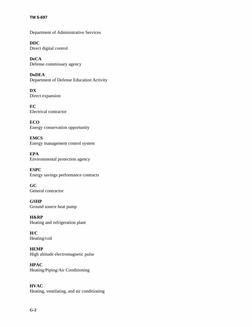
TM 5-697
G-2
Department of Administrative Services DDC Direct digital control DeCA Defense commissary agency DoDEA Department of Defense Education Activity DX Direct expansion EC Electrical contractor ECO Energy conservation opportunity EMCS Energy management control system EPA Environmental protection agency ESPC Energy savings performance contracts GC General contractor GSHP Ground source heat pump H&RP Heating and refrigeration plant H/C Heating/coil HEMP High altitude electromagnetic pulse HPAC Heating/Piping/Air Conditioning HVAC Heating, ventilating, and air conditioning

TM 5-697
G-3
IAQS Indoor air quality system IM&T Information management and technology MC Mechanical contractor NaOH Sodium hydroxide Na2SO3 Sodium sulfate NC Normally closed NFPA National fire protection association NO Normally open NPDES National pollution discharge elimination system N2H2 Hydrazine O & M Operating and maintenance O/O Owner/operator OSHA Occupational health and safety administration O2 Oxygen O3 Ozone P&Ids Piping and Instrumentation Design

TM 5-697
G-4
PIV Post indicator valves PLC Program Logic Controller PP Pneumatic positioner PPM Parts per million PSIG Per square inch gauge PTHP Package terminal heat pump PVC Polyvinyl chloride PVT Performance verification testing RMCS Refrigerant management and control system SMACNA Sheet Metal and Air-Conditioning Contractors’ National Association, Inc. TAB Testing, adjusting, and balancing USACERL United States Army Construction Engineers Research Laboratories USAF United States Air Force UV Ultraviolet VAV Variable air volume VLV Variable liquid volume Section II

TM 5-697
G-5
Terms Acceptance When a system’s readiness for operation has been demonstrated, verified, documented, and authorized. Acceptance test Functional performance test has replaced this terminology. Authority having jurisdiction An individual designated by government, the insuring institution and/or the company, who has knowledge of company operations, fire protection systems, and liability to life and property and who has the authority to stop operation of the facility when certain fire protection requirements are not met. Commissioning The systematic process of verifying, documenting, and ensuring that the systems in a new facility are designed, installed, functionally tested, and capable of being operated and maintained to perform according to the original design intent and owners’ requirements. The process begins in the facilities program phase and progresses through design, construction/start-up, functional performance testing, and post functional performance phases, and lasts at least one year after project-closeout. Commissioning activities include training of operations and maintenance staff. During commissioning, functional performance tests and deferred functional performance tests are conducted on each system. These tests require written authorization for the systems to be accepted as ready for operation in the commissioning process. The commissioning process can be applied throughout the life of the facility (see re-commissioning). Commissioning requires the participation of all parties involved in the facility delivery cycle from the program phase to the post acceptance phase. Deferred functional performance tests Functional performance tests which cannot be accomplished immediately and need to be deferred to a later time because of seasonal reasons, lack of occupancy, deficiencies in other systems, or structures impacting the system under consideration or other reasons. A comprehensive acceptance test schedule including deferred acceptance tests should be developed as part of the acceptance test plan. Design basis document All information necessary to accomplish the design intent, including weather data, interior environmental criteria, other pertinent design assumptions, cost goals, and references to applicable codes, standards, regulations, and guidelines. Design intent A detailed explanation of the ideas, concepts, and criteria that are defined by the owner to be important. This typically is an expansion of the information provided in the owner’s program. Final acceptance When all requirements of the commissioning process/plan have been completely satisfied, documented, and authorized as accepted. At this point all of the systems in a facility are deemed ready for operation. Final acceptance occurs at the completion of the post acceptance period and may take one year in duration. Functional performance test

TM 5-697
G-6
The full range of checks and tests carried out to determine whether all components, subsystems, systems, and interfaces between systems function in accordance with the contract documents. In this contest, “function” includes all modes and sequences of control operation, all interlocks, and conditional control responses and all specified responses during design day and emergency conditions High altitude electromagnetic pulses (HEMP) HEMP are generated from the explosion of a nuclear bomb at high altitude. The burst from the bomb may cause large currents or potential differences to be induced in many types of conductors. This energy can couple to wires or any conductor above or below aground and induce signals which cause malfunctioning or destruction of sensitive equipment used in C4ISR facilities. Post acceptance The period of time occurring after project-closeout and before final acceptance. The post acceptance period may last for one year. It includes time for remaining or all deferred acceptance tests and the guarantee/warrantee period. Pre-Functional Performance Test A series of tests for specified equipment or systems, which determine that the systems are installed correctly, start up, and are prepared for the functional performance tests. Often these tests are in a checklist format. The pre-functional test checklists may be completed as part of the normal contractor start-up test Project-closeout The point in time when the systems are considered acceptable for the owner and/or his operating and maintaining contractor (O & M) take over operation of the facility and its systems. At this time some or all deferred acceptance tests and guarantee/warrantee work will remain to be completed. The post acceptance period begins at project-closeout. Re-commissioning A detailed condition assessment/retesting of an existing facilities’ systems. During re-commissioning, functional performance tests are conducted on systems to establish acceptability. Re-commissioning requires subsequent "tune-ups" and fixes to bring systems back to design or current operating requirements. It includes all aspects of commissioning. Re-commissioning can occur only if a building or system had been previously commissioned. Re-commissioning involves the continued adjustment, optimization, and modification of systems to meet specified requirements. It includes updating documentation resulting from minor set point adjustments, system maintenance and calibration, major system modifications, and provides for ongoing training of operations and maintenance personnel. As in commissioning, re-commissioning requires authorization of satisfactorily completed tests for the systems to be considered acceptable and ready for operation. Retro-commissioning A detailed condition assessment/testing of an existing facilities systems, after the facility has been in operation and for which no commissioning activities have been conducted. Retro-commissioning requires all commissioning activities be performed and may require field work for preparation of drawings and documentation of equipment specifications. Systems Manual A document developed for a system that includes as-built drawings, equipment specifications, and equipment manuals which include installation instructions, operating instructions, maintenance instructions, and approvals from fire department inspectors, city, state, regulatory, and insurance officials.

TM 5-697
G-7
The system manual also includes pertinent information gathered during the commissioning process such as a copy of the signed commissioning sign-off sheet, a table of contents, and a list of all items in the manual.
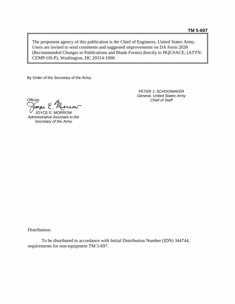
TM 5-697 The proponent agency of this publication is the Chief of Engineers, United States Army. Users are invited to send comments and suggested improvements on DA Form 2028 (Recommended Changes to Publications and Blank Forms) directly to HQUSACE, (ATTN: CEMP-OS-P), Washington, DC 20314-1000.
Distribution:
To be distributed in accordance with Initial Distribution Number (IDN) 344744, requirements for non-equipment TM 5-697.
By Order of the Secretary of the Army:
PETER J. SCHOOMAKER General, United States Army
Chief of Staff Official:
JOYCE E. MORROW Administrative Assistant to the
Secretary of the Army

PIN: 080606-000