table of contents safety mechanical installation ... · safety table of contents mechanical...
TRANSCRIPT
Safety
Table of contents
Mechanical installation
Electrical installation
Start-up and control with I/O
ABB industry-specific drives
Short form user’s manualACS320 drives
List of related manuals
You can find manuals and other product documents in PDF format on the Internet. See section Document library on the Internet on the inside of the back cover. For manuals not available in the Document library, contact your local ABB representative.
Purpose of the manual
This short form user’s manual provides the basic information needed for installing and commissioning the drive.
For information on planning the electrical installation, operation with the control panel, program features, fieldbus, all accessible actual signals and parameters, fault tracing, maintenance, additional technical data and dimension drawings, refer to ACS320 user’s manual (3AUA0000062599 [English]). To access it on the Internet, go to www.abb.com/drives, select Document Library, enter the code in the search field and click OK.
Applicability
The manual is applicable to the ACS320 drive firmware version 4.03c or later. See parameter 3301 FIRMWARE in chapter Actual signals and parameters in ACS320 user’s manual (3AUA0000062599 [English]).
Drive manuals Code (English)ACS320 short form user’s manual 3AUA0000086933ACS320 user’s manual 3AUA0000062599
Option manuals and guidesMFDT-01 FlashDrop user’s manual 3AFE68591074MREL-01 output relay module user’s manual 3AUA0000035974MUL1-R1 installation instructions for ACS150, ACS310, ACS320, ACS350 and ACS355
3AFE68642868
MUL1-R3 installation instructions for ACS310, ACS320, ACS350 and ACS355
3AFE68643147
MUL1-R4 installation instructions for ACS310, ACS320, ACS350 and ACS355
3AUA0000025916
SREA-01 Ethernet adapter module quick start-up guide 3AUA0000042902SREA-01 Ethernet adapter module user’s manual 3AUA0000042896
Maintenance manualsGuide for capacitor reforming in ACS50, ACS55, ACS150, ACS310, ACS350, ACS355, ACS550, ACH550 and R1-R4 OINT-/SINT-boards
3AFE68735190
3AUA0000086933 Rev DENEFFECTIVE: 2016-08-18 2016 ABB Oy. All Rights Reserved.
Table of contents 3
Table of contentsList of related manuals . . . . . . . . . . . . . . . . . . . . . . . . . . . . . . . . . . . . . . . . . . . . . . . . . . . . . . . 2Purpose of the manual . . . . . . . . . . . . . . . . . . . . . . . . . . . . . . . . . . . . . . . . . . . . . . . . . . . . . . . 2Applicability . . . . . . . . . . . . . . . . . . . . . . . . . . . . . . . . . . . . . . . . . . . . . . . . . . . . . . . . . . . . . . . . 2
1. Safety
Safety in installation and maintenance . . . . . . . . . . . . . . . . . . . . . . . . . . . . . . . . . . . . . . . . . . . 5Safe start-up and operation . . . . . . . . . . . . . . . . . . . . . . . . . . . . . . . . . . . . . . . . . . . . . . . . . . . . 6
2. Hardware description
Power connections and control interfaces . . . . . . . . . . . . . . . . . . . . . . . . . . . . . . . . . . . . . . . . . 9Type designation label . . . . . . . . . . . . . . . . . . . . . . . . . . . . . . . . . . . . . . . . . . . . . . . . . . . . . . . 10Type designation key . . . . . . . . . . . . . . . . . . . . . . . . . . . . . . . . . . . . . . . . . . . . . . . . . . . . . . . . 11
3. Mechanical installation
Installing . . . . . . . . . . . . . . . . . . . . . . . . . . . . . . . . . . . . . . . . . . . . . . . . . . . . . . . . . . . . . . . . . 13
4. Electrical installation
Checking the compatibility with IT (ungrounded) and corner-grounded TN systems . . . . . . . 17Connecting the power cables . . . . . . . . . . . . . . . . . . . . . . . . . . . . . . . . . . . . . . . . . . . . . . . . . 19Connecting the control cables . . . . . . . . . . . . . . . . . . . . . . . . . . . . . . . . . . . . . . . . . . . . . . . . . 21Installation checklist . . . . . . . . . . . . . . . . . . . . . . . . . . . . . . . . . . . . . . . . . . . . . . . . . . . . . . . . . 23
5. Start-up and control with I/O
How to start up the drive . . . . . . . . . . . . . . . . . . . . . . . . . . . . . . . . . . . . . . . . . . . . . . . . . . . . . 25How to control the drive through the I/O interface . . . . . . . . . . . . . . . . . . . . . . . . . . . . . . . . . . 32
6. Actual signals and parameters in the short view
Terms and abbreviations . . . . . . . . . . . . . . . . . . . . . . . . . . . . . . . . . . . . . . . . . . . . . . . . . . . . . 33Fieldbus equivalent . . . . . . . . . . . . . . . . . . . . . . . . . . . . . . . . . . . . . . . . . . . . . . . . . . . . . . . . . 33Default values with different macros . . . . . . . . . . . . . . . . . . . . . . . . . . . . . . . . . . . . . . . . . . . . 34Actual signals in the short parameter view . . . . . . . . . . . . . . . . . . . . . . . . . . . . . . . . . . . . . . . 38Parameters in the short parameter view . . . . . . . . . . . . . . . . . . . . . . . . . . . . . . . . . . . . . . . . . 39
7. Technical data
Ratings . . . . . . . . . . . . . . . . . . . . . . . . . . . . . . . . . . . . . . . . . . . . . . . . . . . . . . . . . . . . . . . . . . 47Definitions . . . . . . . . . . . . . . . . . . . . . . . . . . . . . . . . . . . . . . . . . . . . . . . . . . . . . . . . . . . . . . . . 48Fuses and alternate short-circuit protection . . . . . . . . . . . . . . . . . . . . . . . . . . . . . . . . . . . . . . 50UL marking . . . . . . . . . . . . . . . . . . . . . . . . . . . . . . . . . . . . . . . . . . . . . . . . . . . . . . . . . . . . . . . 53
Safety

4 Table of contents
Further information
Product and service inquiries . . . . . . . . . . . . . . . . . . . . . . . . . . . . . . . . . . . . . . . . . . . . . . . . . 57Product training . . . . . . . . . . . . . . . . . . . . . . . . . . . . . . . . . . . . . . . . . . . . . . . . . . . . . . . . . . . 57Providing feedback on ABB Drives manuals . . . . . . . . . . . . . . . . . . . . . . . . . . . . . . . . . . . . . 57Document library on the Internet . . . . . . . . . . . . . . . . . . . . . . . . . . . . . . . . . . . . . . . . . . . . . . 57
Safety 5
1. Safety
Safety in installation and maintenance
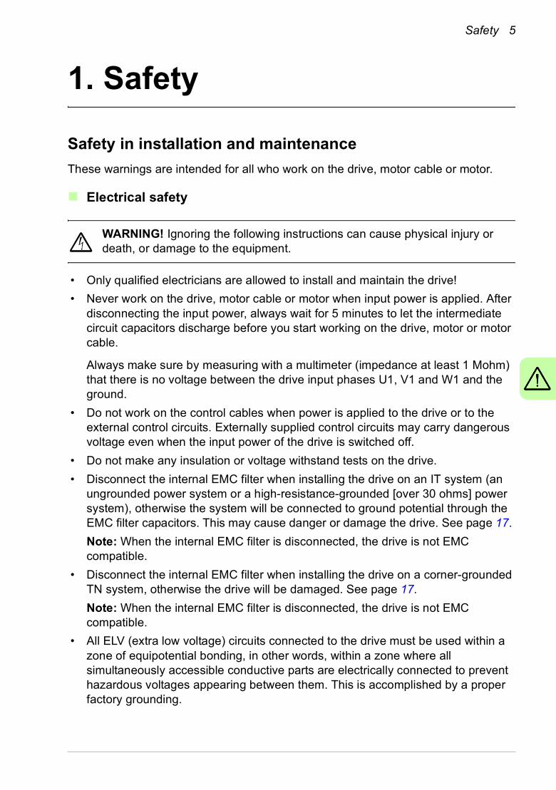
These warnings are intended for all who work on the drive, motor cable or motor.
Electrical safety
WARNING! Ignoring the following instructions can cause physical injury or death, or damage to the equipment.
• Only qualified electricians are allowed to install and maintain the drive!
• Never work on the drive, motor cable or motor when input power is applied. After disconnecting the input power, always wait for 5 minutes to let the intermediate circuit capacitors discharge before you start working on the drive, motor or motor cable.
Always make sure by measuring with a multimeter (impedance at least 1 Mohm) that there is no voltage between the drive input phases U1, V1 and W1 and the ground.
• Do not work on the control cables when power is applied to the drive or to the external control circuits. Externally supplied control circuits may carry dangerous voltage even when the input power of the drive is switched off.
• Do not make any insulation or voltage withstand tests on the drive.
• Disconnect the internal EMC filter when installing the drive on an IT system (an ungrounded power system or a high-resistance-grounded [over 30 ohms] power system), otherwise the system will be connected to ground potential through the EMC filter capacitors. This may cause danger or damage the drive. See page 17.
Note: When the internal EMC filter is disconnected, the drive is not EMC compatible.
• Disconnect the internal EMC filter when installing the drive on a corner-grounded TN system, otherwise the drive will be damaged. See page 17.
Note: When the internal EMC filter is disconnected, the drive is not EMC compatible.
• All ELV (extra low voltage) circuits connected to the drive must be used within a zone of equipotential bonding, in other words, within a zone where all simultaneously accessible conductive parts are electrically connected to prevent hazardous voltages appearing between them. This is accomplished by a proper factory grounding.
6 Safety
Note:
• Even when the motor is stopped, dangerous voltage is present at the power circuit terminals U1, V1, W1 and U2, V2, W2.
• For more technical information, contact the factory or your local ABB sales representative.
General safety
WARNING! If you ignore the safety instructions, injury or death can occur. If you are not a qualified electrician, do not do electrical work.
• Never attempt to repair a malfunctioning drive. Contact your local ABB representative or Authorized Service Center for service support.
• Make sure that dust from drilling does not enter the drive during the installation. Electrically conductive dust inside the drive may cause damage or lead to malfunction.
• Make sure of sufficient cooling.
Safe start-up and operation
These warnings are intended for all who plan the operation, start up or operate the drive.
General safety
WARNING! Ignoring the following instructions can cause physical injury or death, or damage to the equipment.
• Before adjusting the drive and putting it into service, make sure that the motor and all driven equipment are suitable for operation throughout the speed range provided by the drive. The drive can be adjusted to operate the motor at speeds above and below the speed provided by connecting the motor directly to the power line.
• Do not activate automatic fault reset functions if dangerous situations can occur. When activated, these functions will reset the drive and resume operation after a fault.
• Do not control the motor with an AC contactor or disconnecting device (disconnecting means). Use the control panel start and stop keys and or external commands (I/O or fieldbus). The maximum number of charging cycles allowed with the DC capacitors (i.e power-ups by applying power) is two per minute and the maximum total number of chargings is 15 000.
Safety 7
Note:
• If an external source is selected for start command, and it is ON, the drive starts immediately after an input voltage break or fault reset unless the drive is configured for 3-wire (a pulse) start/stop.
• When the control location is not set to local (LOC not shown on the display), the stop key on the control panel will not stop the drive. To stop the drive using the control panel, press the LOC/REM key and then press the stop key .LOC
REM

8 Safety
Hardware description 9
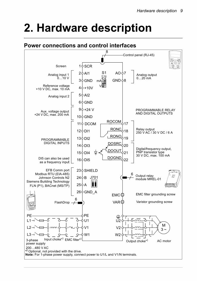
2. Hardware descriptionPower connections and control interfaces
RONO
RONC
3
9
DI1
DI2
DI3
DI4
DI5
+24 VAux. voltage output+24 V DC, max. 200 mA
DOSRC
GND
DCOM
DOOUT
DOGND
Digital/frequency output,PNP transistor type30 V DC, max. 100 mA
Relay output 250 V AC / 30 V DC / 6 A
V
mAGND
+10VReference voltage
+10 V DC, max. 10 mA
AI2Analog input 2
GND
AI1Analog input 10…10 V
SCRScreen
Analog output0…20 mAA
I1A
I2
*) Optional, not provided with the drive.Note: For 1-phase power supply, connect power to U1/L and V1/N terminals.
EMC
VAR
EMC filter grounding screw
Varistor grounding screw
ROCOM
PROGRAMMABLE RELAY AND DIGITAL OUTPUTS
Output relay module MREL-01
11 17
18
19
20
21
22
AO 7
GND 8
12
13
14
15
16
10
6
5
1
2
SHIELD
B
A
GND_A
23
24
25
26
PROGRAMMABLEDIGITAL INPUTS
4
FlashDrop
S1
J701
8
6
6
DI5 can also be usedas a frequency input
L1
L2
L3
PEU1
V1
W1
PE
Input choke*) EMC filter*)3-phase power supply
U2
V2
W2
AC motor
M3 ~
Output choke*)
Control panel (RJ-45)
EFB Comm portModbus RTU (EIA-485)
Johnson Controls N2Siemens Building Technology
FLN (P1), BACnet (MS/TP)
200…480 V AC
10 Hardware description
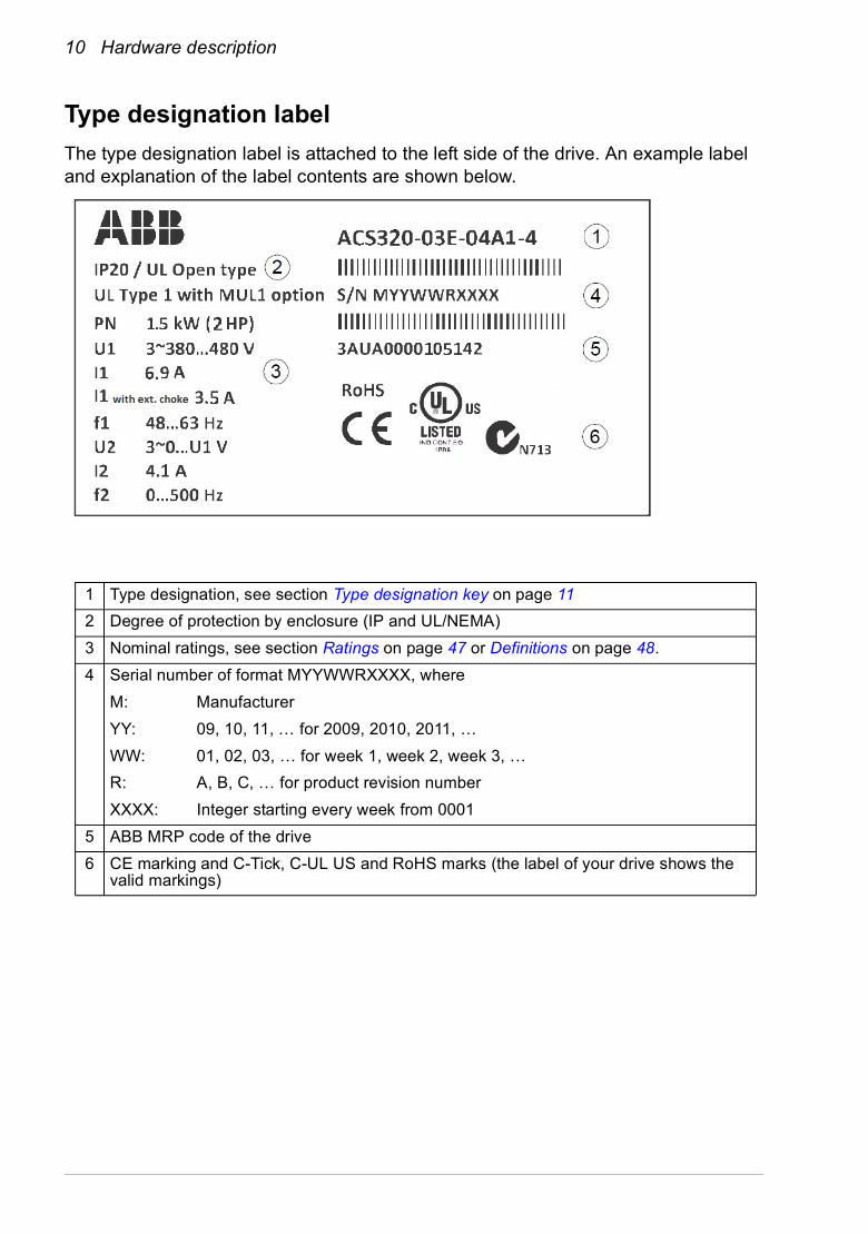
Type designation label
The type designation label is attached to the left side of the drive. An example label and explanation of the label contents are shown below.
1 Type designation, see section Type designation key on page 11
2 Degree of protection by enclosure (IP and UL/NEMA)
3 Nominal ratings, see section Ratings on page 47 or Definitions on page 48.
4 Serial number of format MYYWWRXXXX, where
M: Manufacturer
YY: 09, 10, 11, … for 2009, 2010, 2011, …
WW: 01, 02, 03, … for week 1, week 2, week 3, …
R: A, B, C, … for product revision number
XXXX: Integer starting every week from 0001
5 ABB MRP code of the drive
6 CE marking and C-Tick, C-UL US and RoHS marks (the label of your drive shows the valid markings)
Hardware description 11
Type designation key
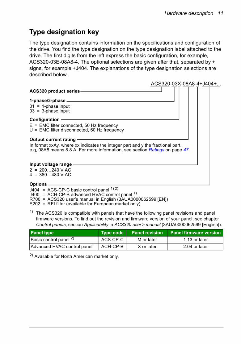
The type designation contains information on the specifications and configuration of the drive. You find the type designation on the type designation label attached to the drive. The first digits from the left express the basic configuration, for example, ACS320-03E-08A8-4. The optional selections are given after that, separated by + signs, for example +J404. The explanations of the type designation selections are described below.
ACS320-03X-08A8-4+J404+...
ACS320 product series
01 = 1-phase input03 = 3-phase input
1-phase/3-phase
In format xxAy, where xx indicates the integer part and y the fractional part, e.g, 08A8 means 8.8 A. For more information, see section Ratings on page 47.
2 = 200…240 V AC4 = 380…480 V AC
Input voltage range
E = EMC filter connected, 50 Hz frequencyU = EMC filter disconnected, 60 Hz frequency
Configuration
J404 = ACS-CP-C basic control panel 1) 2)
J400 = ACH-CP-B advanced HVAC control panel 1)
R700 = ACS320 user’s manual in English (3AUA0000062599 [EN])E202 = RFI filter (available for European market only)
1) The ACS320 is compatible with panels that have the following panel revisions and panel firmware versions. To find out the revision and firmware version of your panel, see chapter Control panels, section Applicability in ACS320 user’s manual (3AUA0000062599 [English]).
2) Available for North American market only.
Panel type Type code Panel revision Panel firmware version
Basic control panel 2) ACS-CP-C M or later 1.13 or later
Advanced HVAC control panel ACH-CP-B X or later 2.04 or later
Options
Output current rating

12 Hardware description

Mechanical installation 13
3. Mechanical installation
Installing
The instructions in this manual cover drives with the IP20 degree of protection. To comply with NEMA 1, use the MUL1-R1, MUL1-R3 or MUL1-R4 option kit, which is delivered with multilingual installation instructions (3AFE68642868, 3AFE68643147 or 3AUA0000025916, respectively).
Install the drive
Install the drive with screws or on a DIN rail as appropriate.
The required free space for cooling above and below the drive is 75 mm (3 in). No free space is required on the sides, so drives can be mounted immediately next to each other.
Note: Make sure that dust from drilling does not enter the drive during the installation.
With screws
1. Mark the hole locations using for example the mounting template cut out from the package. The locations of the holes are also shown in the drawings in chapter Dimension drawings in ACS320 user’s manual (3AUA0000062599 [English]). The number and location of the holes used depend on how the drive is installed:
a) back mounting (frame sizes R0…R4): four holes
b) side mounting (frame sizes R0…R2): three holes; one of the bottom holes is located in the clamping plate.
2. Fix the screws or bolts to the marked locations.
1 22
14 Mechanical installation
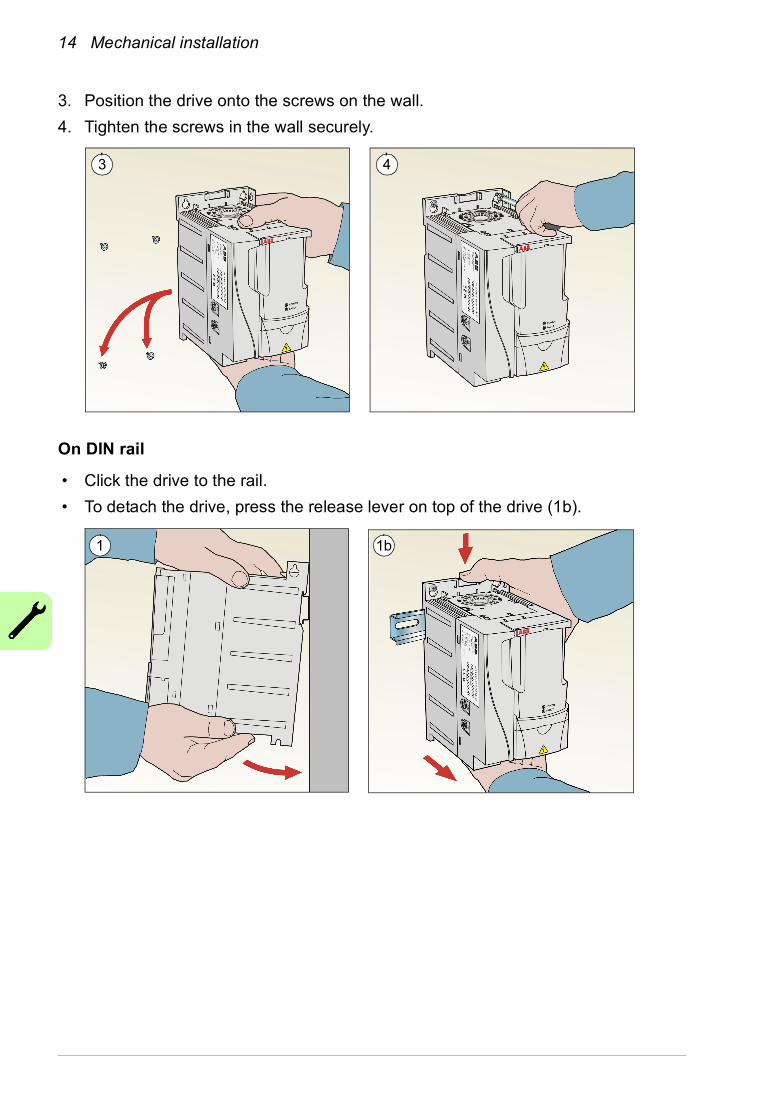
3. Position the drive onto the screws on the wall.
4. Tighten the screws in the wall securely.
On DIN rail
• Click the drive to the rail.
• To detach the drive, press the release lever on top of the drive (1b).
3 4
1 1b
Mechanical installation 15
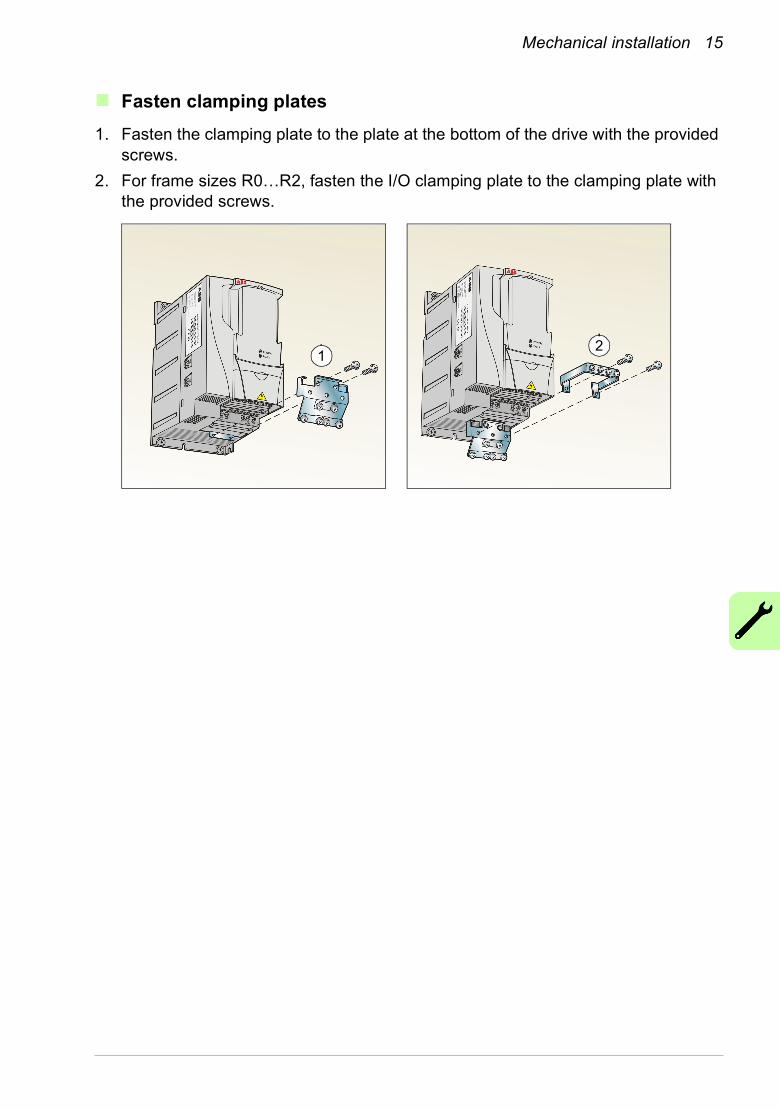
Fasten clamping plates
1. Fasten the clamping plate to the plate at the bottom of the drive with the provided screws.
2. For frame sizes R0…R2, fasten the I/O clamping plate to the clamping plate with the provided screws.
12

16 Mechanical installation
Electrical installation 17
4. Electrical installation
WARNING! Obey the safety instructions. See chapter Safety on page 5. If you ignore the safety instructions, injury or death can occur. If you are not a qualified electrician, do not do electrical work.
Make sure that the drive is disconnected from the input power during installation. If the drive is already connected to the input power, wait for 5 minutes after disconnecting the input power.
Checking the compatibility with IT (ungrounded) and corner-grounded TN systems
WARNING! Disconnect the internal EMC filter when installing the drive on an IT system (an ungrounded power system or a high-resistance-grounded [over 30 ohms] power system), otherwise the system will be connected to ground
potential through the EMC filter capacitors. This may cause danger or damage the drive.
Disconnect the internal EMC filter when installing the drive on a corner-grounded TN system, otherwise the drive will be damaged.
Note: When the internal EMC filter is disconnected, the drive is not EMC compatible without an external filter.
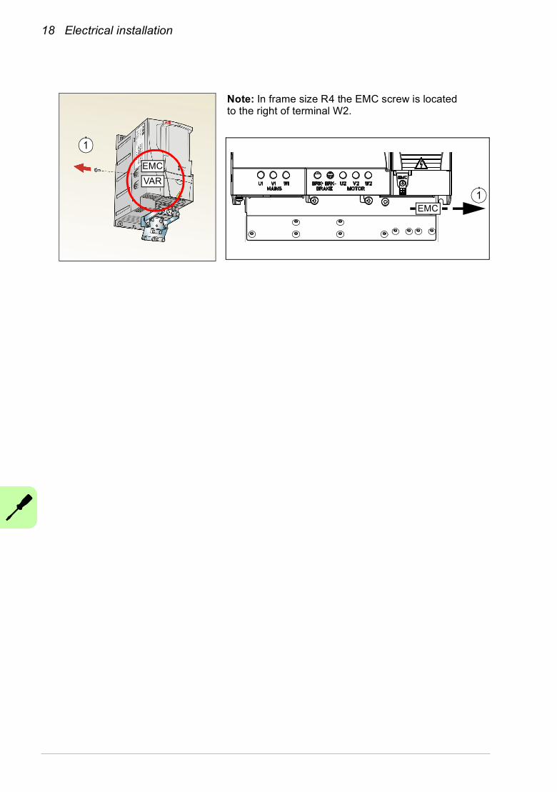
1. If you have an IT (ungrounded) or corner grounded TN system, disconnect the internal EMC filter by removing the EMC screw. For 3-phase U-type drives (with type designation ACS320-03U-), the EMC screw is already removed at the factory and replaced by a plastic one.Pay attention to the screws! Do not confuse the EMC screw to the similar varistor disconnecting screw. Do not disconnect the varistor. The varistor protects the drive against power line voltage peaks.
18 Electrical installation
Note: In frame size R4 the EMC screw is located to the right of terminal W2.
1
EMC
VAR
1EMC
Electrical installation 19
Connecting the power cables
Connection diagram
U2 V2 W2
INPUT
1)
Drive
For alternatives, see chapter Planning the electrical installation, section Selecting the supply disconnecting device (disconnecting means) in ACS320 user’s manual (3AUA0000062599 [English]).
OUTPUT
U1/L V1/N W1
Motor3 ~
V1U1 W1
PE
PE
L1 L2 L3
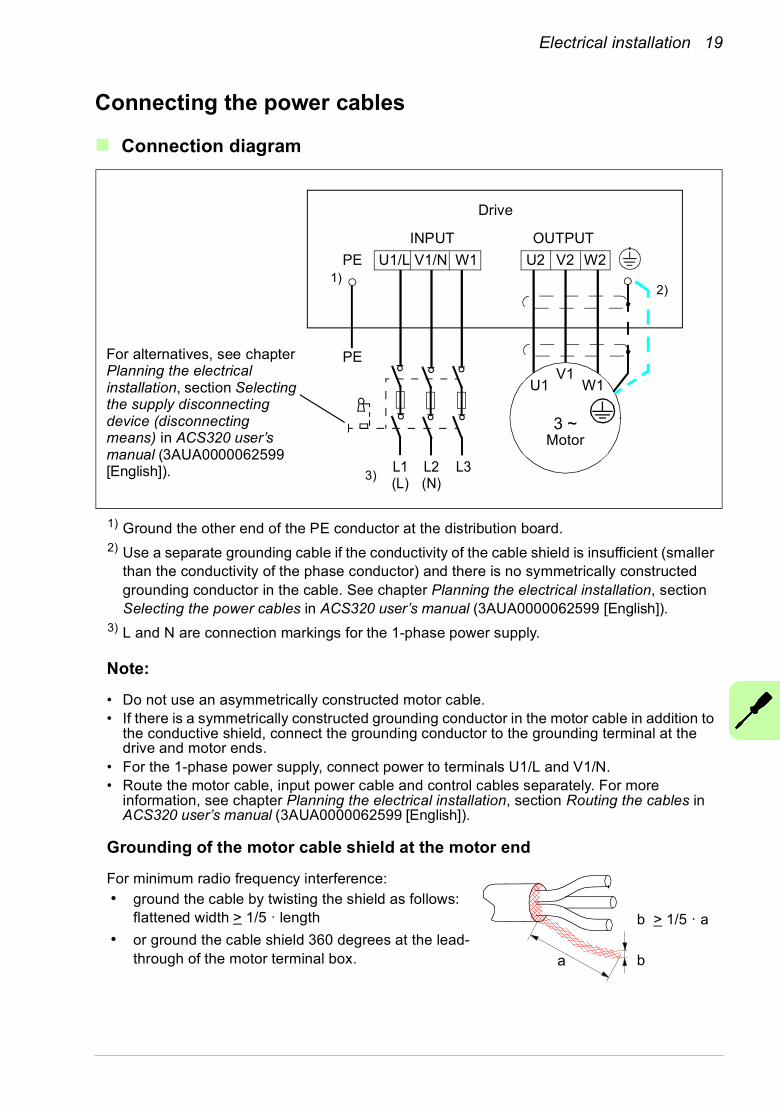
1) Ground the other end of the PE conductor at the distribution board.2) Use a separate grounding cable if the conductivity of the cable shield is insufficient (smaller
than the conductivity of the phase conductor) and there is no symmetrically constructed grounding conductor in the cable. See chapter Planning the electrical installation, section Selecting the power cables in ACS320 user’s manual (3AUA0000062599 [English]).
3) L and N are connection markings for the 1-phase power supply.
Note:
• Do not use an asymmetrically constructed motor cable. • If there is a symmetrically constructed grounding conductor in the motor cable in addition to
the conductive shield, connect the grounding conductor to the grounding terminal at the drive and motor ends.
• For the 1-phase power supply, connect power to terminals U1/L and V1/N.• Route the motor cable, input power cable and control cables separately. For more
information, see chapter Planning the electrical installation, section Routing the cables in ACS320 user’s manual (3AUA0000062599 [English]).
Grounding of the motor cable shield at the motor end
For minimum radio frequency interference:• ground the cable by twisting the shield as follows:
flattened width > 1/5 · length
• or ground the cable shield 360 degrees at the lead-through of the motor terminal box. a b
b > 1/5 · a
2)
(L) (N)3)
20 Electrical installation
Connection procedure
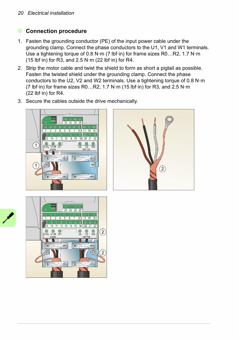
1. Fasten the grounding conductor (PE) of the input power cable under the grounding clamp. Connect the phase conductors to the U1, V1 and W1 terminals. Use a tightening torque of 0.8 N·m (7 lbf·in) for frame sizes R0…R2, 1.7 N·m (15 lbf·in) for R3, and 2.5 N·m (22 lbf·in) for R4.
2. Strip the motor cable and twist the shield to form as short a pigtail as possible. Fasten the twisted shield under the grounding clamp. Connect the phase conductors to the U2, V2 and W2 terminals. Use a tightening torque of 0.8 N·m (7 lbf·in) for frame sizes R0…R2, 1.7 N·m (15 lbf·in) for R3, and 2.5 N·m (22 lbf·in) for R4.
3. Secure the cables outside the drive mechanically.
1
1
2
2
2
Electrical installation 21
Connecting the control cables
Default I/O connection diagram
The default connection of the control signals depends on the application macro in use, which is selected with parameter 9902 APPLIC MACRO.
The default macro is the HVAC Default macro. It provides a general purpose I/O configuration with three constant speeds. Parameter values are the default values given in chapter Actual signals and parameters in ACS320 user’s manual (3AUA0000062599 [English]).
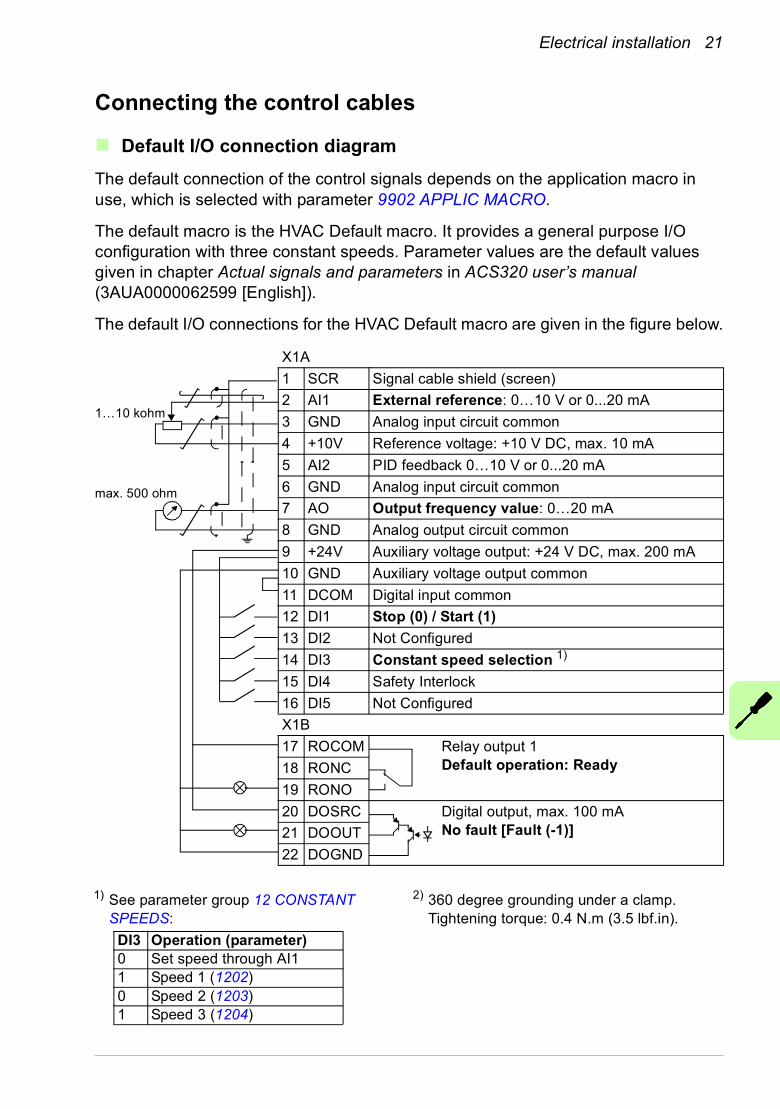
The default I/O connections for the HVAC Default macro are given in the figure below.
X1A
1 SCR Signal cable shield (screen)
2 AI1 External reference: 0…10 V or 0...20 mA
3 GND Analog input circuit common
4 +10V Reference voltage: +10 V DC, max. 10 mA
5 AI2 PID feedback 0…10 V or 0...20 mA
6 GND Analog input circuit common
7 AO Output frequency value: 0…20 mA
8 GND Analog output circuit common
9 +24V Auxiliary voltage output: +24 V DC, max. 200 mA
10 GND Auxiliary voltage output common
11 DCOM Digital input common
12 DI1 Stop (0) / Start (1)
13 DI2 Not Configured
14 DI3 Constant speed selection 1)
15 DI4 Safety Interlock
16 DI5 Not Configured
X1B
17 ROCOM Relay output 1Default operation: Ready18 RONC
19 RONO
20 DOSRC Digital output, max. 100 mANo fault [Fault (-1)]21 DOOUT
22 DOGND
max. 500 ohm
1…10 kohm
1) See parameter group 12 CONSTANT SPEEDS:
2) 360 degree grounding under a clamp. Tightening torque: 0.4 N.m (3.5 lbf.in).
DI3 Operation (parameter)0 Set speed through AI11 Speed 1 (1202)0 Speed 2 (1203)1 Speed 3 (1204)
22 Electrical installation
Connection procedure
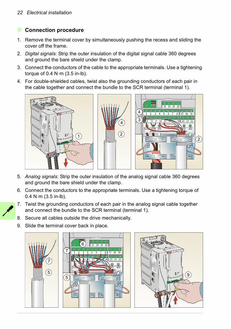
1. Remove the terminal cover by simultaneously pushing the recess and sliding the cover off the frame.
2. Digital signals: Strip the outer insulation of the digital signal cable 360 degrees and ground the bare shield under the clamp.
3. Connect the conductors of the cable to the appropriate terminals. Use a tightening torque of 0.4 N·m (3.5 in-lb).
4. For double-shielded cables, twist also the grounding conductors of each pair in the cable together and connect the bundle to the SCR terminal (terminal 1).
5. Analog signals: Strip the outer insulation of the analog signal cable 360 degrees and ground the bare shield under the clamp.
6. Connect the conductors to the appropriate terminals. Use a tightening torque of 0.4 N·m (3.5 in-lb).
7. Twist the grounding conductors of each pair in the analog signal cable together and connect the bundle to the SCR terminal (terminal 1).
8. Secure all cables outside the drive mechanically.
9. Slide the terminal cover back in place.
2
43
4
21
5
7
4
5
6
7
9
Electrical installation 23
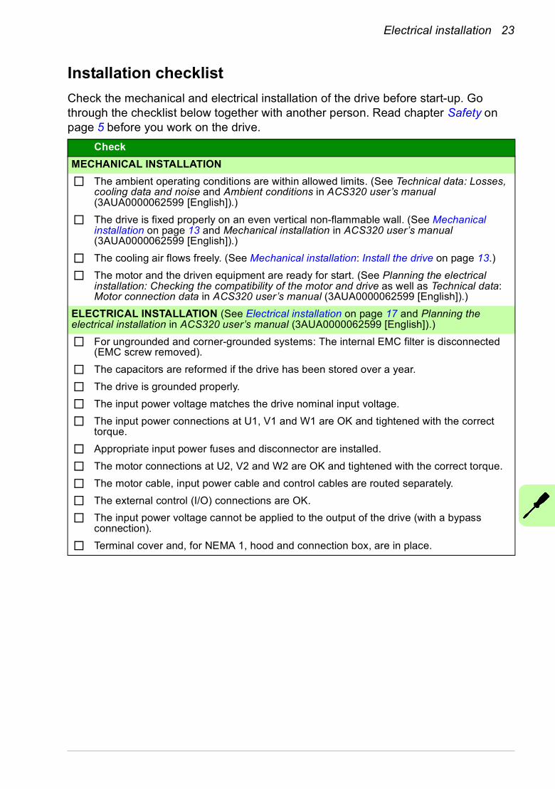
Installation checklist
Check the mechanical and electrical installation of the drive before start-up. Go through the checklist below together with another person. Read chapter Safety on page 5 before you work on the drive.
Check
MECHANICAL INSTALLATION
The ambient operating conditions are within allowed limits. (See Technical data: Losses, cooling data and noise and Ambient conditions in ACS320 user’s manual (3AUA0000062599 [English]).)
The drive is fixed properly on an even vertical non-flammable wall. (See Mechanical installation on page 13 and Mechanical installation in ACS320 user’s manual (3AUA0000062599 [English]).)
The cooling air flows freely. (See Mechanical installation: Install the drive on page 13.)
The motor and the driven equipment are ready for start. (See Planning the electrical installation: Checking the compatibility of the motor and drive as well as Technical data: Motor connection data in ACS320 user’s manual (3AUA0000062599 [English]).)
ELECTRICAL INSTALLATION (See Electrical installation on page 17 and Planning the electrical installation in ACS320 user’s manual (3AUA0000062599 [English]).)
For ungrounded and corner-grounded systems: The internal EMC filter is disconnected (EMC screw removed).
The capacitors are reformed if the drive has been stored over a year.
The drive is grounded properly.
The input power voltage matches the drive nominal input voltage.
The input power connections at U1, V1 and W1 are OK and tightened with the correct torque.
Appropriate input power fuses and disconnector are installed.
The motor connections at U2, V2 and W2 are OK and tightened with the correct torque.
The motor cable, input power cable and control cables are routed separately.
The external control (I/O) connections are OK.
The input power voltage cannot be applied to the output of the drive (with a bypass connection).
Terminal cover and, for NEMA 1, hood and connection box, are in place.

24 Electrical installation
Start-up and control with I/O 25
5. Start-up and control with I/O
How to start up the drive
WARNING! Only qualified electricians are allowed to start-up or operate the drive. Obey the safety instructions. See chapter Safety on page 5.
Before adjusting the drive and putting it into service, make sure that the motor and all driven equipments are suitable for operation throughout the speed range provided by the drive. The drive can be adjusted to operate the motor at speeds above and below the speed provided by connecting the motor directly to the power line.
If an external source for start command is selected and it is ON, the drive will start immediately after an input voltage break or fault reset unless the drive is configured for 3-wire (a pulse) start/stop.
Note: By default, parameter 1611 PARAMETER VIEW is set to 2 (SHORT VIEW), and you cannot see all actual signals and parameters. To be able to view them, set parameter 1611 PARAMETER VIEW to 3 (LONG VIEW).
• Check the installation. See the checklist in section Installation checklist on page 23.
How you start up the drive depends on the control panel you have.
• If you have a Basic control panel, follow the instructions given in section How to perform a manual start-up on page 26.
• If you have an Advanced HVAC control panel, you can either run the Start-up assistant (see section How to perform a guided start-up on page 29) or perform a manual start-up (see section How to perform a manual start-up on page 26).
The Start-up assistant, which is included in the Advanced HVAC control panel only, guides you through all essential settings to be done. In the manual start-up, the drive gives no guidance; you go through the very basic settings by following the instructions given in section How to perform a manual start-up on page 26.
26 Start-up and control with I/O
How to perform a manual start-up
For the manual start-up, you can use the Basic control panel or the Advanced HVAC control panel. The instructions below are valid for both control panels, but the displays shown are the Basic control panel displays, unless the instruction applies to the Advanced HVAC control panel only.
Before you start, make sure that you have the motor nameplate data on hand.
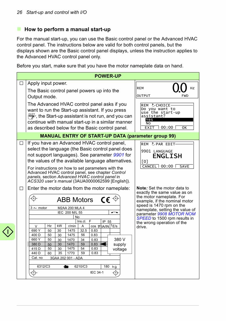
POWER-UP
Apply input power.
The Basic control panel powers up into the Output mode.
The Advanced HVAC control panel asks if you want to run the Start-up assistant. If you press
, the Start-up assistant is not run, and you can continue with manual start-up in a similar manner as described below for the Basic control panel.
MANUAL ENTRY OF START-UP DATA (parameter group 99)
If you have an Advanced HVAC control panel, select the language (the Basic control panel does not support languages). See parameter 9901 for the values of the available language alternatives.
For instructions on how to set parameters with the Advanced HVAC control panel, see chapter Control panels, section Advanced HVAC control panel in ACS320 user’s manual (3AUA0000062599 [English]).
Enter the motor data from the motor nameplate: Note: Set the motor data to exactly the same value as on the motor nameplate. For example, if the nominal motor speed is 1470 rpm on the nameplate, setting the value of parameter 9908 MOTOR NOM SPEED to 1500 rpm results in the wrong operation of the drive.
REM Hz
OUTPUT FWD00.
EXIT
Do you want touse the start-upassistant?YesNoEXIT OK00:00
REM CHOICE
9901 LANGUAGE
CANCEL SAVE00:00
PAR EDIT
[0]ENGLISH
REM
M2AA 200 MLA 4
14751475
1470147014751770
32.556
34595459
0.830.83
0.830.830.830.83
3GAA 202 001 - ADA
180
IEC 34-1
6210/C36312/C3
Cat. no 35 30 30 30
30 3050
5050
505060
690 Y400 D660 Y380 D415 D440 D
V Hz kW r/min A cos IA/IN t E/s
Ins.cl. F IP 55No
IEC 200 M/L 553 motor
ABB Motors
380 Vsupplyvoltage
Start-up and control with I/O 27
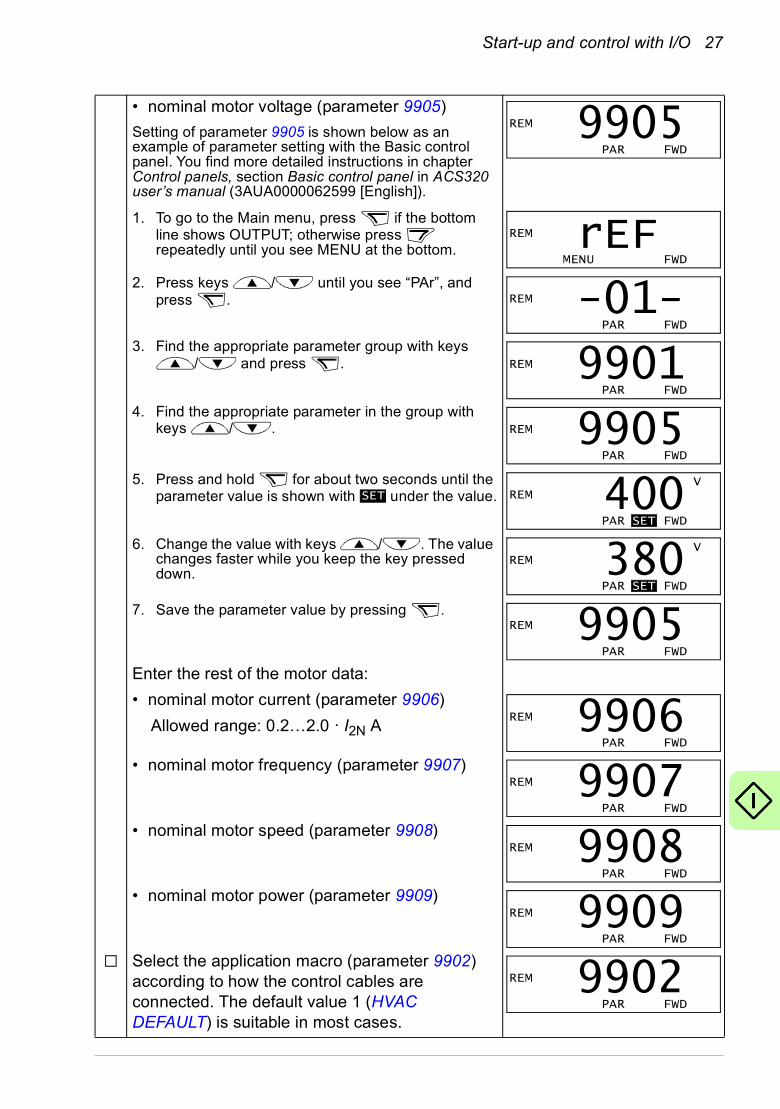
• nominal motor voltage (parameter 9905)
Setting of parameter 9905 is shown below as an example of parameter setting with the Basic control panel. You find more detailed instructions in chapter Control panels, section Basic control panel in ACS320 user’s manual (3AUA0000062599 [English]).
1. To go to the Main menu, press if the bottom line shows OUTPUT; otherwise press repeatedly until you see MENU at the bottom.
2. Press keys / until you see “PAr”, and press .
3. Find the appropriate parameter group with keys / and press .
4. Find the appropriate parameter in the group with keys / .
5. Press and hold for about two seconds until the parameter value is shown with under the value.
6. Change the value with keys / . The value changes faster while you keep the key pressed down.
7. Save the parameter value by pressing .
Enter the rest of the motor data:
• nominal motor current (parameter 9906)
Allowed range: 0.2…2.0 · I2N A
• nominal motor frequency (parameter 9907)
• nominal motor speed (parameter 9908)
• nominal motor power (parameter 9909)
Select the application macro (parameter 9902) according to how the control cables are connected. The default value 1 (HVAC DEFAULT) is suitable in most cases.
REM
PAR FWD9905
REM
MENU FWDrEF
REM
PAR FWD-01-
REM
PAR FWD9901
REM
PAR FWD9905
SETV
REM
PAR SET FWD400
VREM
PAR SET FWD380
REM
PAR FWD9905
REM
PAR FWD9906
REM
PAR FWD9907
REM
PAR FWD9908
REM
PAR FWD9909
REM
PAR FWD9902
28 Start-up and control with I/O
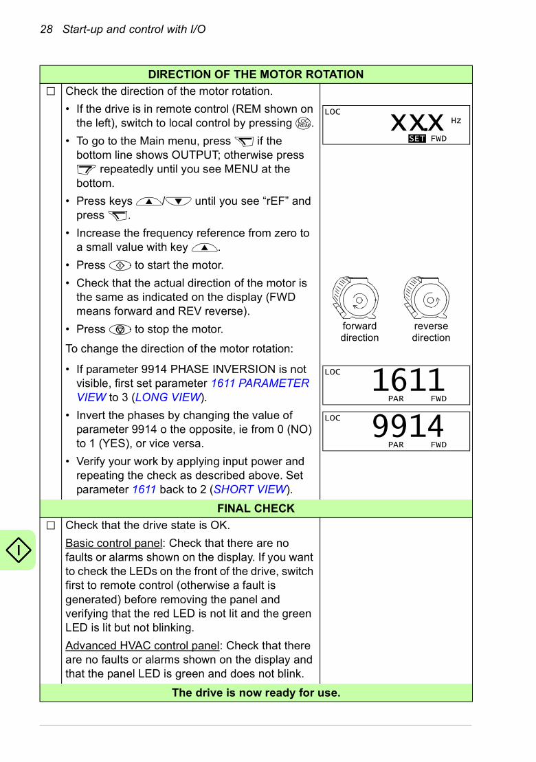
DIRECTION OF THE MOTOR ROTATION
Check the direction of the motor rotation.
• If the drive is in remote control (REM shown on the left), switch to local control by pressing .
• To go to the Main menu, press if the bottom line shows OUTPUT; otherwise press
repeatedly until you see MENU at the bottom.
• Press keys / until you see “rEF” and press .
• Increase the frequency reference from zero to a small value with key .
• Press to start the motor.
• Check that the actual direction of the motor is the same as indicated on the display (FWD means forward and REV reverse).
• Press to stop the motor.
To change the direction of the motor rotation:
• If parameter 9914 PHASE INVERSION is not visible, first set parameter 1611 PARAMETER VIEW to 3 (LONG VIEW).
• Invert the phases by changing the value of parameter 9914 o the opposite, ie from 0 (NO) to 1 (YES), or vice versa.
• Verify your work by applying input power and repeating the check as described above. Set parameter 1611 back to 2 (SHORT VIEW).
FINAL CHECK
Check that the drive state is OK.
Basic control panel: Check that there are no faults or alarms shown on the display. If you want to check the LEDs on the front of the drive, switch first to remote control (otherwise a fault is generated) before removing the panel and verifying that the red LED is not lit and the green LED is lit but not blinking.
Advanced HVAC control panel: Check that there are no faults or alarms shown on the display and that the panel LED is green and does not blink.
The drive is now ready for use.
LOCREM
LOCHz
SET FWDxxx.
forward direction
reverse direction
LOC
PAR FWD1611
LOC
PAR FWD9914
Start-up and control with I/O 29
How to perform a guided start-up
To be able to perform the guided start-up, you need the Advanced HVAC control panel.
Before you start, make sure that you have the motor nameplate data on hand.
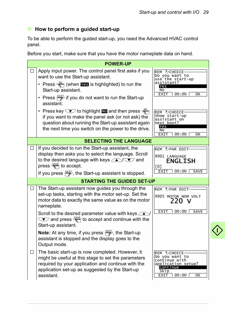
POWER-UP
Apply input power. The control panel first asks if you want to use the Start-up assistant.
• Press (when is highlighted) to run the Start-up assistant.
• Press if you do not want to run the Start-up assistant.
• Press key to highlight and then press if you want to make the panel ask (or not ask) the question about running the Start-up assistant again the next time you switch on the power to the drive.
SELECTING THE LANGUAGE
If you decided to run the Start-up assistant, the display then asks you to select the language. Scroll to the desired language with keys / and press to accept.
If you press , the Start-up assistant is stopped.
STARTING THE GUIDED SET-UP
The Start-up assistant now guides you through the set-up tasks, starting with the motor set-up. Set the motor data to exactly the same value as on the motor nameplate.
Scroll to the desired parameter value with keys / and press to accept and continue with the
Start-up assistant.
Note: At any time, if you press , the Start-up assistant is stopped and the display goes to the Output mode.
The basic start-up is now completed. However, it might be useful at this stage to set the parameters required by your application and continue with the application set-up as suggested by the Start-up assistant.
OKYes
EXIT
Do you want touse the start-upassistant?YesNoEXIT OK00:00
REM CHOICE
NoOK
Show start-upassistant onnext boot?YesNoEXIT OK00:00
REM CHOICE
SAVE
EXIT
9901 LANGUAGE
EXIT SAVE00:00
PAR EDIT
[0]ENGLISH
REM
SAVE
EXIT
9905 MOTOR NOM VOLT
EXIT SAVE00:00
PAR EDIT
220 V
REM
Do you want tocontinue withapplication setup?ContinueSkipEXIT OK00:00
REM CHOICE
30 Start-up and control with I/O
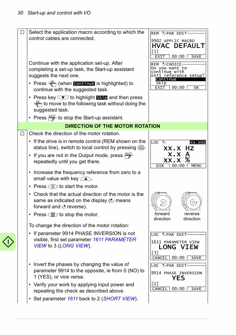
Select the application macro according to which the control cables are connected.
Continue with the application set-up. After completing a set-up task, the Start-up assistant suggests the next one.
• Press (when is highlighted) to continue with the suggested task.
• Press key to highlight and then press to move to the following task without doing the
suggested task.
• Press to stop the Start-up assistant.
DIRECTION OF THE MOTOR ROTATION
Check the direction of the motor rotation.
• If the drive is in remote control (REM shown on the status line), switch to local control by pressing .
• If you are not in the Output mode, press repeatedly until you get there.
• Increase the frequency reference from zero to a small value with key .
• Press to start the motor.
• Check that the actual direction of the motor is the same as indicated on the display ( means forward and reverse).
• Press to stop the motor.
To change the direction of the motor rotation:
• If parameter 9914 PHASE INVERSION is not visible, first set parameter 1611 PARAMETER VIEW to 3 (LONG VIEW).
• Invert the phases by changing the value of parameter 9914 to the opposite, ie from 0 (NO) to 1 (YES), or vice versa.
• Verify your work by applying input power and repeating the check as described above.
• Set parameter 1611 back to 2 (SHORT VIEW).
9902 APPLIC MACRO
EXIT SAVE00:00
PAR EDIT
[1]HVAC DEFAULT
REM
OKContinue
SkipOK
EXIT
Do you want tocontinue withEXT1 reference setup?ContinueSkipEXIT OK00:00
REM CHOICE
LOCREM
EXIT
DIR MENU00:00
LOC xx.xHz
xx x Hz.x x A.
xx x %.
forward direction
reverse direction
1611 PARAMETER VIEW
CANCEL SAVE00:00
PAR EDIT
[3]LONG VIEW
LOC
9914 PHASE INVERSION
CANCEL SAVE00:00
LOC
[1]YES
PAR EDIT

Start-up and control with I/O 31
FINAL CHECK
After the whole set-up is completed, check that there are no faults or alarms shown on the display and the panel LED is green and does not blink.
The drive is now ready for use.
32 Start-up and control with I/O
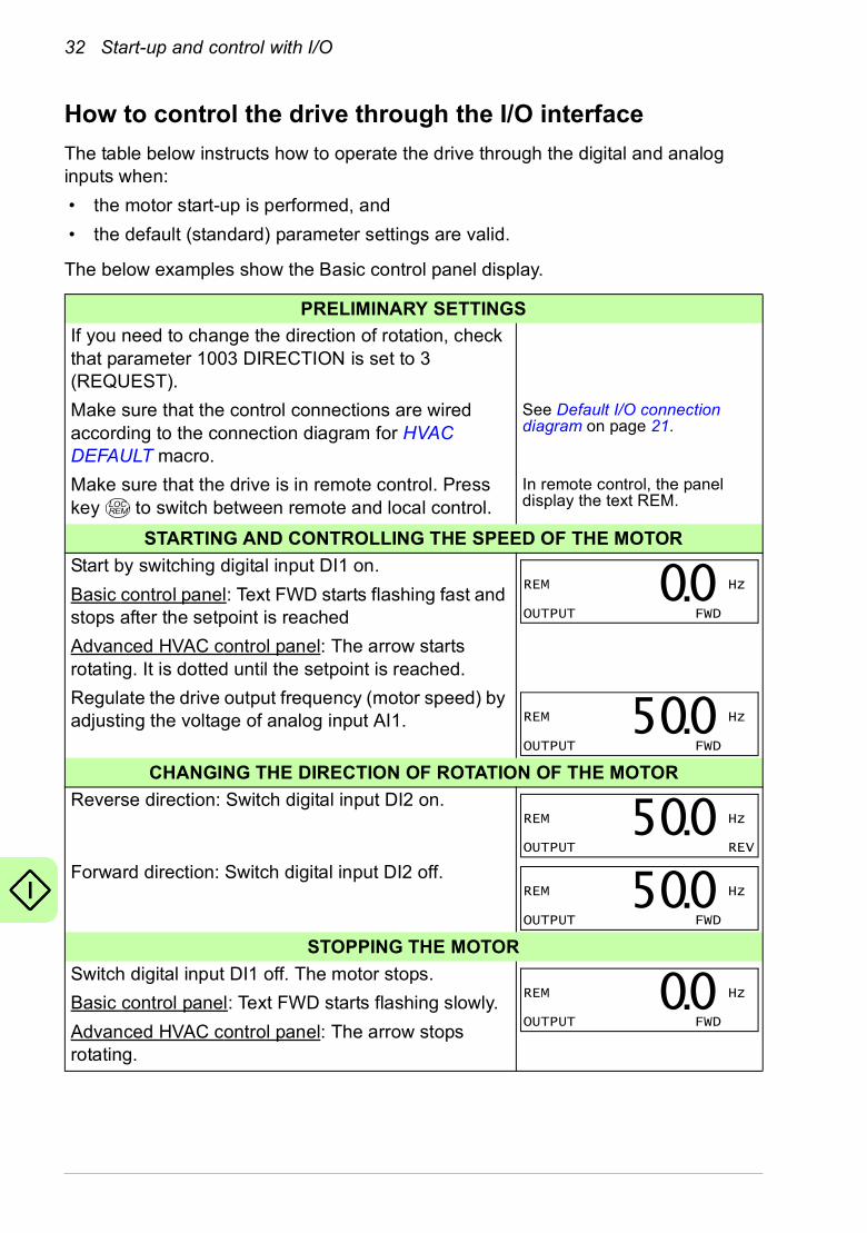
How to control the drive through the I/O interface
The table below instructs how to operate the drive through the digital and analog inputs when:
• the motor start-up is performed, and
• the default (standard) parameter settings are valid.
The below examples show the Basic control panel display.
PRELIMINARY SETTINGS
If you need to change the direction of rotation, check that parameter 1003 DIRECTION is set to 3 (REQUEST).
Make sure that the control connections are wired according to the connection diagram for HVAC DEFAULT macro.
See Default I/O connection diagram on page 21.
Make sure that the drive is in remote control. Press key to switch between remote and local control.
In remote control, the panel display the text REM.
STARTING AND CONTROLLING THE SPEED OF THE MOTOR
Start by switching digital input DI1 on.
Basic control panel: Text FWD starts flashing fast and stops after the setpoint is reached
Advanced HVAC control panel: The arrow starts rotating. It is dotted until the setpoint is reached.
Regulate the drive output frequency (motor speed) by adjusting the voltage of analog input AI1.
CHANGING THE DIRECTION OF ROTATION OF THE MOTOR
Reverse direction: Switch digital input DI2 on.
Forward direction: Switch digital input DI2 off.
STOPPING THE MOTOR
Switch digital input DI1 off. The motor stops.
Basic control panel: Text FWD starts flashing slowly.
Advanced HVAC control panel: The arrow stops rotating.
LOCREM
REM Hz
OUTPUT FWD00.
REM Hz
OUTPUT FWD500.
REM Hz
OUTPUT REV500.
REM Hz
OUTPUT FWD500.
REM Hz
OUTPUT FWD00.
Actual signals and parameters in the short view 33
6. Actual signals and parameters in the short view
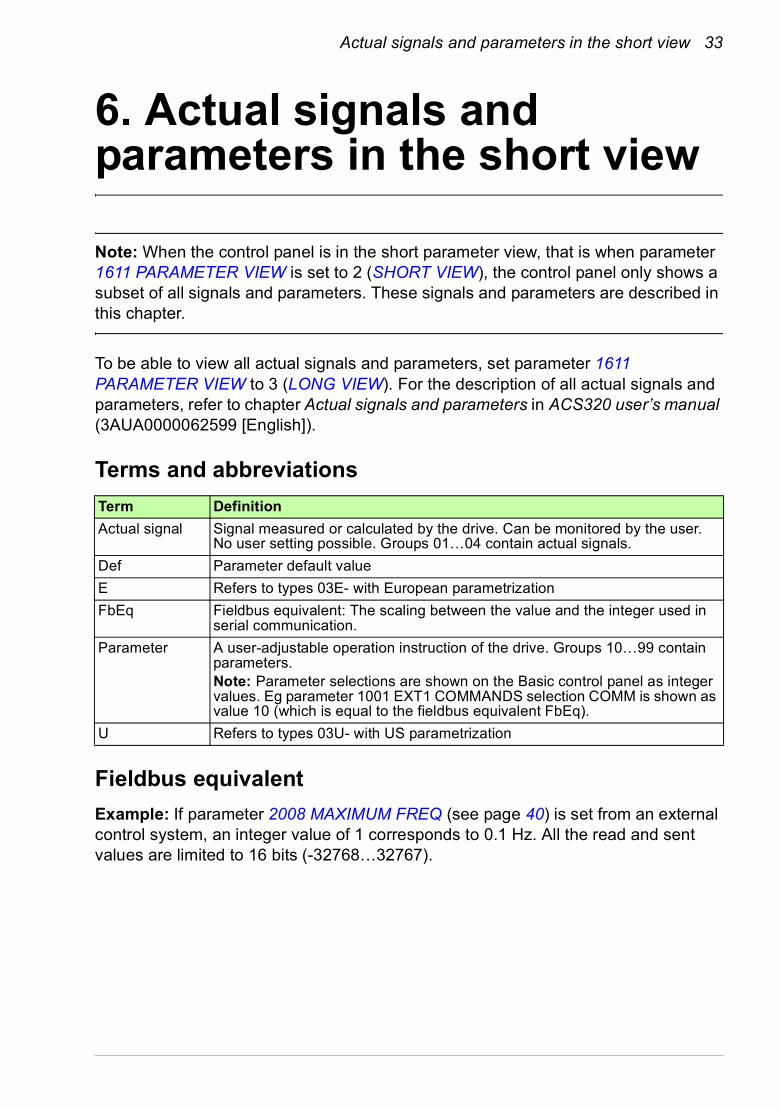
Note: When the control panel is in the short parameter view, that is when parameter 1611 PARAMETER VIEW is set to 2 (SHORT VIEW), the control panel only shows a subset of all signals and parameters. These signals and parameters are described in this chapter.
To be able to view all actual signals and parameters, set parameter 1611 PARAMETER VIEW to 3 (LONG VIEW). For the description of all actual signals and parameters, refer to chapter Actual signals and parameters in ACS320 user’s manual (3AUA0000062599 [English]).
Terms and abbreviations
Fieldbus equivalent
Example: If parameter 2008 MAXIMUM FREQ (see page 40) is set from an external control system, an integer value of 1 corresponds to 0.1 Hz. All the read and sent values are limited to 16 bits (-32768…32767).
Term Definition
Actual signal Signal measured or calculated by the drive. Can be monitored by the user. No user setting possible. Groups 01…04 contain actual signals.
Def Parameter default value
E Refers to types 03E- with European parametrization
FbEq Fieldbus equivalent: The scaling between the value and the integer used in serial communication.
Parameter A user-adjustable operation instruction of the drive. Groups 10…99 contain parameters.Note: Parameter selections are shown on the Basic control panel as integer values. Eg parameter 1001 EXT1 COMMANDS selection COMM is shown as value 10 (which is equal to the fieldbus equivalent FbEq).
U Refers to types 03U- with US parametrization
34 Actual signals and parameters in the short view
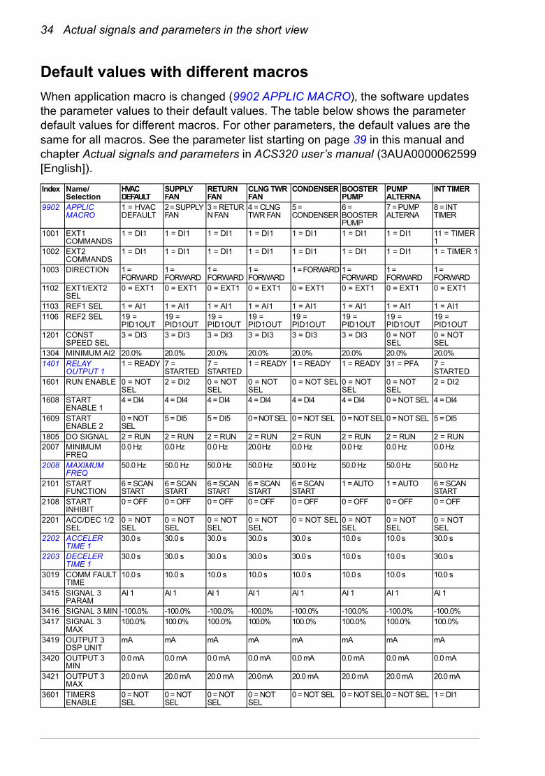
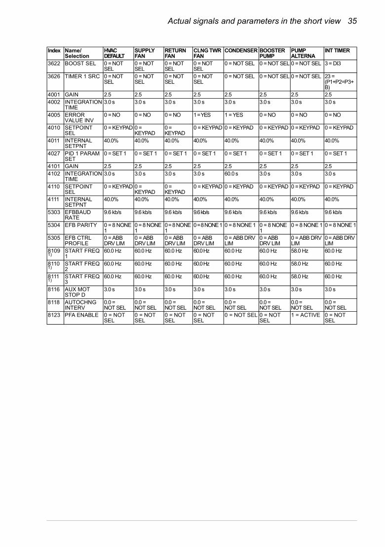
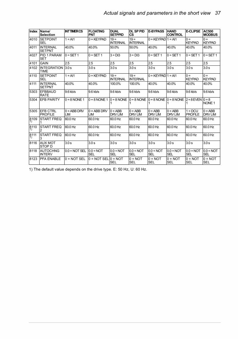
Default values with different macros
When application macro is changed (9902 APPLIC MACRO), the software updates the parameter values to their default values. The table below shows the parameter default values for different macros. For other parameters, the default values are the same for all macros. See the parameter list starting on page 39 in this manual and chapter Actual signals and parameters in ACS320 user’s manual (3AUA0000062599 [English]).
Index Name/Selection
HVAC DEFAULT
SUPPLY FAN
RETURN FAN
CLNG TWR FAN
CONDENSER BOOSTER PUMP
PUMP ALTERNA
INT TIMER
9902 APPLIC MACRO
1 = HVAC DEFAULT
2 = SUPPLY FAN
3 = RETURN FAN
4 = CLNG TWR FAN
5 = CONDENSER
6 = BOOSTER PUMP
7 = PUMP ALTERNA
8 = INT TIMER
1001 EXT1 COMMANDS
1 = DI1 1 = DI1 1 = DI1 1 = DI1 1 = DI1 1 = DI1 1 = DI1 11 = TIMER 1
1002 EXT2 COMMANDS
1 = DI1 1 = DI1 1 = DI1 1 = DI1 1 = DI1 1 = DI1 1 = DI1 1 = TIMER 1
1003 DIRECTION 1 = FORWARD
1 = FORWARD
1 = FORWARD
1 = FORWARD
1 = FORWARD 1 = FORWARD
1 = FORWARD
1 = FORWARD
1102 EXT1/EXT2 SEL
0 = EXT1 0 = EXT1 0 = EXT1 0 = EXT1 0 = EXT1 0 = EXT1 0 = EXT1 0 = EXT1
1103 REF1 SEL 1 = AI1 1 = AI1 1 = AI1 1 = AI1 1 = AI1 1 = AI1 1 = AI1 1 = AI11106 REF2 SEL 19 =
PID1OUT19 = PID1OUT
19 = PID1OUT
19 = PID1OUT
19 = PID1OUT
19 = PID1OUT
19 = PID1OUT
19 = PID1OUT
1201 CONST SPEED SEL
3 = DI3 3 = DI3 3 = DI3 3 = DI3 3 = DI3 3 = DI3 0 = NOT SEL
0 = NOT SEL
1304 MINIMUM AI2 20.0% 20.0% 20.0% 20.0% 20.0% 20.0% 20.0% 20.0%1401 RELAY
OUTPUT 11 = READY 7 =
STARTED7 = STARTED
1 = READY 1 = READY 1 = READY 31 = PFA 7 = STARTED
1601 RUN ENABLE 0 = NOT SEL
2 = DI2 0 = NOT SEL
0 = NOT SEL
0 = NOT SEL 0 = NOT SEL
0 = NOT SEL
2 = DI2
1608 START ENABLE 1
4 = DI4 4 = DI4 4 = DI4 4 = DI4 4 = DI4 4 = DI4 0 = NOT SEL 4 = DI4
1609 START ENABLE 2
0 = NOT SEL
5 = DI5 5 = DI5 0 = NOT SEL 0 = NOT SEL 0 = NOT SEL 0 = NOT SEL 5 = DI5
1805 DO SIGNAL 2 = RUN 2 = RUN 2 = RUN 2 = RUN 2 = RUN 2 = RUN 2 = RUN 2 = RUN2007 MINIMUM
FREQ0.0 Hz 0.0 Hz 0.0 Hz 20.0 Hz 0.0 Hz 0.0 Hz 0.0 Hz 0.0 Hz
2008 MAXIMUM FREQ
50.0 Hz 50.0 Hz 50.0 Hz 50.0 Hz 50.0 Hz 50.0 Hz 50.0 Hz 50.0 Hz
2101 START FUNCTION
6 = SCAN START
6 = SCAN START
6 = SCAN START
6 = SCAN START
6 = SCAN START
1 = AUTO 1 = AUTO 6 = SCAN START
2108 START INHIBIT
0 = OFF 0 = OFF 0 = OFF 0 = OFF 0 = OFF 0 = OFF 0 = OFF 0 = OFF
2201 ACC/DEC 1/2 SEL
0 = NOT SEL
0 = NOT SEL
0 = NOT SEL
0 = NOT SEL
0 = NOT SEL 0 = NOT SEL
0 = NOT SEL
0 = NOT SEL
2202 ACCELER TIME 1
30.0 s 30.0 s 30.0 s 30.0 s 30.0 s 10.0 s 10.0 s 30.0 s
2203 DECELER TIME 1
30.0 s 30.0 s 30.0 s 30.0 s 30.0 s 10.0 s 10.0 s 30.0 s
3019 COMM FAULT TIME
10.0 s 10.0 s 10.0 s 10.0 s 10.0 s 10.0 s 10.0 s 10.0 s
3415 SIGNAL 3 PARAM
AI 1 AI 1 AI 1 AI 1 AI 1 AI 1 AI 1 AI 1
3416 SIGNAL 3 MIN -100.0% -100.0% -100.0% -100.0% -100.0% -100.0% -100.0% -100.0%3417 SIGNAL 3
MAX100.0% 100.0% 100.0% 100.0% 100.0% 100.0% 100.0% 100.0%
3419 OUTPUT 3 DSP UNIT
mA mA mA mA mA mA mA mA
3420 OUTPUT 3 MIN
0.0 mA 0.0 mA 0.0 mA 0.0 mA 0.0 mA 0.0 mA 0.0 mA 0.0 mA
3421 OUTPUT 3 MAX
20.0 mA 20.0 mA 20.0 mA 20.0 mA 20.0 mA 20.0 mA 20.0 mA 20.0 mA
3601 TIMERS ENABLE
0 = NOT SEL
0 = NOT SEL
0 = NOT SEL
0 = NOT SEL
0 = NOT SEL 0 = NOT SEL 0 = NOT SEL 1 = DI1
Actual signals and parameters in the short view 35
3622 BOOST SEL 0 = NOT SEL
0 = NOT SEL
0 = NOT SEL
0 = NOT SEL
0 = NOT SEL 0 = NOT SEL 0 = NOT SEL 3 = DI3
3626 TIMER 1 SRC 0 = NOT SEL
0 = NOT SEL
0 = NOT SEL
0 = NOT SEL
0 = NOT SEL 0 = NOT SEL 0 = NOT SEL 23 = (P1+P2=P3+B)
4001 GAIN 2.5 2.5 2.5 2.5 2.5 2.5 2.5 2.54002 INTEGRATION
TIME3.0 s 3.0 s 3.0 s 3.0 s 3.0 s 3.0 s 3.0 s 3.0 s
4005 ERROR VALUE INV
0 = NO 0 = NO 0 = NO 1 = YES 1 = YES 0 = NO 0 = NO 0 = NO
4010 SETPOINT SEL
0 = KEYPAD 0 = KEYPAD
0 = KEYPAD
0 = KEYPAD 0 = KEYPAD 0 = KEYPAD 0 = KEYPAD 0 = KEYPAD
4011 INTERNAL SETPNT
40.0% 40.0% 40.0% 40.0% 40.0% 40.0% 40.0% 40.0%
4027 PID 1 PARAM SET
0 = SET 1 0 = SET 1 0 = SET 1 0 = SET 1 0 = SET 1 0 = SET 1 0 = SET 1 0 = SET 1
4101 GAIN 2.5 2.5 2.5 2.5 2.5 2.5 2.5 2.54102 INTEGRATION
TIME3.0 s 3.0 s 3.0 s 3.0 s 60.0 s 3.0 s 3.0 s 3.0 s
4110 SETPOINT SEL
0 = KEYPAD 0 = KEYPAD
0 = KEYPAD
0 = KEYPAD 0 = KEYPAD 0 = KEYPAD 0 = KEYPAD 0 = KEYPAD
4111 INTERNAL SETPNT
40.0% 40.0% 40.0% 40.0% 40.0% 40.0% 40.0% 40.0%
5303 EFBBAUD RATE
9.6 kb/s 9.6 kb/s 9.6 kb/s 9.6 kb/s 9.6 kb/s 9.6 kb/s 9.6 kb/s 9.6 kb/s
5304 EFB PARITY 0 = 8 NONE 1
0 = 8 NONE 1
0 = 8 NONE 1
0 = 8 NONE 1 0 = 8 NONE 1 0 = 8 NONE 1
0 = 8 NONE 1 0 = 8 NONE 1
5305 EFB CTRL PROFILE
0 = ABB DRV LIM
0 = ABB DRV LIM
0 = ABB DRV LIM
0 = ABB DRV LIM
0 = ABB DRV LIM
0 = ABB DRV LIM
0 = ABB DRV LIM
0 = ABB DRV LIM
8109 1)
START FREQ 1
60.0 Hz 60.0 Hz 60.0 Hz 60.0 Hz 60.0 Hz 60.0 Hz 58.0 Hz 60.0 Hz
8110 1)
START FREQ 2
60.0 Hz 60.0 Hz 60.0 Hz 60.0 Hz 60.0 Hz 60.0 Hz 58.0 Hz 60.0 Hz
8111 1)
START FREQ 3
60.0 Hz 60.0 Hz 60.0 Hz 60.0 Hz 60.0 Hz 60.0 Hz 58.0 Hz 60.0 Hz
8116 AUX MOT STOP D
3.0 s 3.0 s 3.0 s 3.0 s 3.0 s 3.0 s 3.0 s 3.0 s
8118 AUTOCHNG INTERV
0.0 = NOT SEL
0.0 = NOT SEL
0.0 = NOT SEL
0.0 = NOT SEL
0.0 = NOT SEL
0.0 = NOT SEL
0.0 = NOT SEL
0.0 = NOT SEL
8123 PFA ENABLE 0 = NOT SEL
0 = NOT SEL
0 = NOT SEL
0 = NOT SEL
0 = NOT SEL 0 = NOT SEL
1 = ACTIVE 0 = NOT SEL
Index Name/Selection
HVAC DEFAULT
SUPPLY FAN
RETURN FAN
CLNG TWR FAN
CONDENSER BOOSTER PUMP
PUMP ALTERNA
INT TIMER
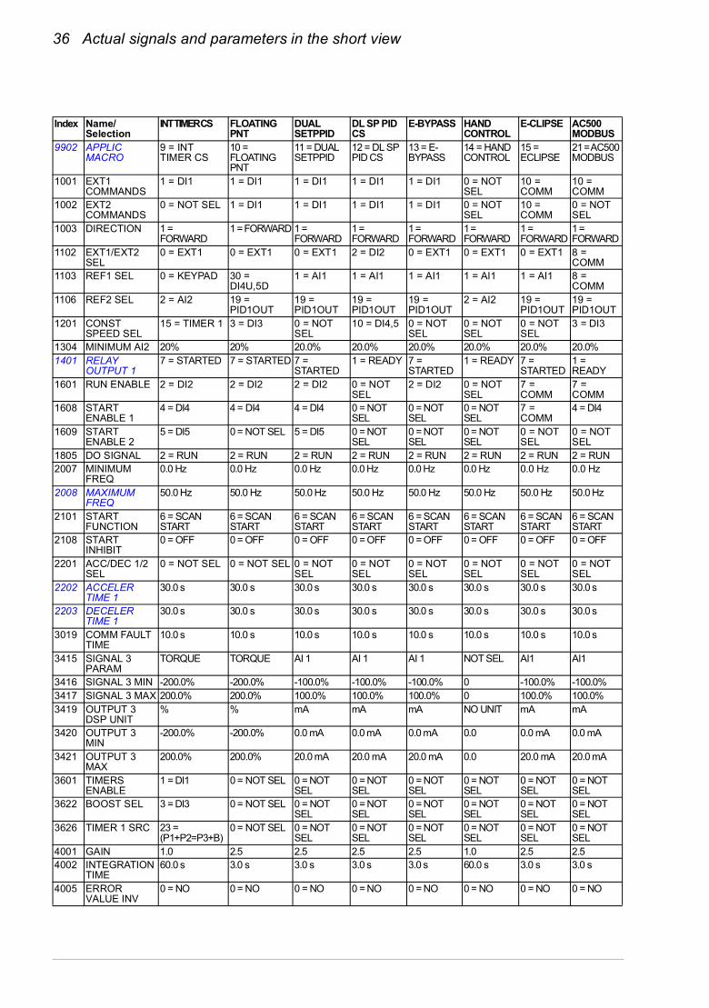
36 Actual signals and parameters in the short view
Index Name/Selection
INT TIMER CS FLOATING PNT
DUAL SETPPID
DL SP PID CS
E-BYPASS HAND CONTROL
E-CLIPSE AC500 MODBUS
9902 APPLIC MACRO
9 = INT TIMER CS
10 = FLOATING PNT
11 = DUAL SETPPID
12 = DL SP PID CS
13 = E-BYPASS
14 = HAND CONTROL
15 = ECLIPSE
21 = AC500 MODBUS
1001 EXT1 COMMANDS
1 = DI1 1 = DI1 1 = DI1 1 = DI1 1 = DI1 0 = NOT SEL
10 = COMM
10 = COMM
1002 EXT2 COMMANDS
0 = NOT SEL 1 = DI1 1 = DI1 1 = DI1 1 = DI1 0 = NOT SEL
10 = COMM
0 = NOT SEL
1003 DIRECTION 1 = FORWARD
1 = FORWARD 1 = FORWARD
1 = FORWARD
1 = FORWARD
1 = FORWARD
1 = FORWARD
1 = FORWARD
1102 EXT1/EXT2 SEL
0 = EXT1 0 = EXT1 0 = EXT1 2 = DI2 0 = EXT1 0 = EXT1 0 = EXT1 8 = COMM
1103 REF1 SEL 0 = KEYPAD 30 = DI4U,5D
1 = AI1 1 = AI1 1 = AI1 1 = AI1 1 = AI1 8 = COMM
1106 REF2 SEL 2 = AI2 19 = PID1OUT
19 = PID1OUT
19 = PID1OUT
19 = PID1OUT
2 = AI2 19 = PID1OUT
19 = PID1OUT
1201 CONST SPEED SEL
15 = TIMER 1 3 = DI3 0 = NOT SEL
10 = DI4,5 0 = NOT SEL
0 = NOT SEL
0 = NOT SEL
3 = DI3
1304 MINIMUM AI2 20% 20% 20.0% 20.0% 20.0% 20.0% 20.0% 20.0%1401 RELAY
OUTPUT 17 = STARTED 7 = STARTED 7 =
STARTED1 = READY 7 =
STARTED1 = READY 7 =
STARTED1 = READY
1601 RUN ENABLE 2 = DI2 2 = DI2 2 = DI2 0 = NOT SEL
2 = DI2 0 = NOT SEL
7 = COMM
7 = COMM
1608 START ENABLE 1
4 = DI4 4 = DI4 4 = DI4 0 = NOT SEL
0 = NOT SEL
0 = NOT SEL
7 = COMM
4 = DI4
1609 START ENABLE 2
5 = DI5 0 = NOT SEL 5 = DI5 0 = NOT SEL
0 = NOT SEL
0 = NOT SEL
0 = NOT SEL
0 = NOT SEL
1805 DO SIGNAL 2 = RUN 2 = RUN 2 = RUN 2 = RUN 2 = RUN 2 = RUN 2 = RUN 2 = RUN2007 MINIMUM
FREQ0.0 Hz 0.0 Hz 0.0 Hz 0.0 Hz 0.0 Hz 0.0 Hz 0.0 Hz 0.0 Hz
2008 MAXIMUM FREQ
50.0 Hz 50.0 Hz 50.0 Hz 50.0 Hz 50.0 Hz 50.0 Hz 50.0 Hz 50.0 Hz
2101 START FUNCTION
6 = SCAN START
6 = SCAN START
6 = SCAN START
6 = SCAN START
6 = SCAN START
6 = SCAN START
6 = SCAN START
6 = SCAN START
2108 START INHIBIT
0 = OFF 0 = OFF 0 = OFF 0 = OFF 0 = OFF 0 = OFF 0 = OFF 0 = OFF
2201 ACC/DEC 1/2 SEL
0 = NOT SEL 0 = NOT SEL 0 = NOT SEL
0 = NOT SEL
0 = NOT SEL
0 = NOT SEL
0 = NOT SEL
0 = NOT SEL
2202 ACCELER TIME 1
30.0 s 30.0 s 30.0 s 30.0 s 30.0 s 30.0 s 30.0 s 30.0 s
2203 DECELER TIME 1
30.0 s 30.0 s 30.0 s 30.0 s 30.0 s 30.0 s 30.0 s 30.0 s
3019 COMM FAULT TIME
10.0 s 10.0 s 10.0 s 10.0 s 10.0 s 10.0 s 10.0 s 10.0 s
3415 SIGNAL 3 PARAM
TORQUE TORQUE AI 1 AI 1 AI 1 NOT SEL AI1 AI1
3416 SIGNAL 3 MIN -200.0% -200.0% -100.0% -100.0% -100.0% 0 -100.0% -100.0%3417 SIGNAL 3 MAX 200.0% 200.0% 100.0% 100.0% 100.0% 0 100.0% 100.0%3419 OUTPUT 3
DSP UNIT% % mA mA mA NO UNIT mA mA
3420 OUTPUT 3 MIN
-200.0% -200.0% 0.0 mA 0.0 mA 0.0 mA 0.0 0.0 mA 0.0 mA
3421 OUTPUT 3 MAX
200.0% 200.0% 20.0 mA 20.0 mA 20.0 mA 0.0 20.0 mA 20.0 mA
3601 TIMERS ENABLE
1 = DI1 0 = NOT SEL 0 = NOT SEL
0 = NOT SEL
0 = NOT SEL
0 = NOT SEL
0 = NOT SEL
0 = NOT SEL
3622 BOOST SEL 3 = DI3 0 = NOT SEL 0 = NOT SEL
0 = NOT SEL
0 = NOT SEL
0 = NOT SEL
0 = NOT SEL
0 = NOT SEL
3626 TIMER 1 SRC 23 = (P1+P2=P3+B)
0 = NOT SEL 0 = NOT SEL
0 = NOT SEL
0 = NOT SEL
0 = NOT SEL
0 = NOT SEL
0 = NOT SEL
4001 GAIN 1.0 2.5 2.5 2.5 2.5 1.0 2.5 2.54002 INTEGRATION
TIME60.0 s 3.0 s 3.0 s 3.0 s 3.0 s 60.0 s 3.0 s 3.0 s
4005 ERROR VALUE INV
0 = NO 0 = NO 0 = NO 0 = NO 0 = NO 0 = NO 0 = NO 0 = NO
Actual signals and parameters in the short view 37
1) The default value depends on the drive type. E: 50 Hz, U: 60 Hz.
4010 SETPOINT SEL
1 = AI1 0 = KEYPAD 19 = INTERNAL
19 = INTERNAL
0 = KEYPAD 1 = AI1 0 = KEYPAD
0 = KEYPAD
4011 INTERNAL SETPNT
40.0% 40.0% 50.0% 50.0% 40.0% 40.0% 40.0% 40.0%
4027 PID 1 PARAM SET
0 = SET 1 0 = SET 1 3 = DI3 3 = DI3 0 = SET 1 0 = SET 1 0 = SET 1 0 = SET 1
4101 GAIN 2.5 2.5 2.5 2.5 2.5 2.5 2.5 2.54102 INTEGRATION
TIME3.0 s 3.0 s 3.0 s 3.0 s 3.0 s 3.0 s 3.0 s 3.0 s
4110 SETPOINT SEL
1 = AI1 0 = KEYPAD 19 = INTERNAL
19 = INTERNAL
0 = KEYPAD 1 = AI1 0 = KEYPAD
0 = KEYPAD
4111 INTERNAL SETPNT
40.0% 40.0% 100.0% 100.0% 40.0% 40.0% 40.0% 40.0%
5303 EFBBAUD RATE
9.6 kb/s 9.6 kb/s 9.6 kb/s 9.6 kb/s 9.6 kb/s 9.6 kb/s 9.6 kb/s 9.6 kb/s
5304 EFB PARITY 0 = 8 NONE 1 0 = 8 NONE 1 0 = 8 NONE 1
0 = 8 NONE 1
0 = 8 NONE 1
0 = 8 NONE 1
2 = 8 EVEN 1
0 = 8 NONE 1
5305 EFB CTRL PROFILE
0 = ABB DRV LIM
0 = ABB DRV LIM
0 = ABB DRV LIM
0 = ABB DRV LIM
0 = ABB DRV LIM
0 = ABB DRV LIM
1 = DCU PROFILE
0 = ABB DRV LIM
8109 1)
START FREQ 1
60.0 Hz 60.0 Hz 60.0 Hz 60.0 Hz 60.0 Hz 60.0 Hz 60.0 Hz 60.0 Hz
8110 1)
START FREQ 2
60.0 Hz 60.0 Hz 60.0 Hz 60.0 Hz 60.0 Hz 60.0 Hz 60.0 Hz 60.0 Hz
8111 1)
START FREQ 3
60.0 Hz 60.0 Hz 60.0 Hz 60.0 Hz 60.0 Hz 60.0 Hz 60.0 Hz 60.0 Hz
8116 AUX MOT STOP D
3.0 s 3.0 s 3.0 s 3.0 s 3.0 s 3.0 s 3.0 s 3.0 s
8118 AUTOCHNG INTERV
0.0 = NOT SEL 0.0 = NOT SEL
0.0 = NOT SEL
0.0 = NOT SEL
0.0 = NOT SEL
0.0 = NOT SEL
0.0 = NOT SEL
0.0 = NOT SEL
8123 PFA ENABLE 0 = NOT SEL 0 = NOT SEL 0 = NOT SEL
0 = NOT SEL
0 = NOT SEL
0 = NOT SEL
0 = NOT SEL
0 = NOT SEL
Index Name/Selection
INT TIMER CS FLOATING PNT
DUAL SETPPID
DL SP PID CS
E-BYPASS HAND CONTROL
E-CLIPSE AC500 MODBUS

38 Actual signals and parameters in the short view
Actual signals in the short parameter view
Actual signals in the short parameter view
No. Name/Value Description FbEq
04 FAULT HISTORY Fault history (read-only)
0401 LAST FAULT Code of the latest fault. See chapter Fault tracing in ACS320 user’s manual (3AUA0000062599 [English]) for the codes. 0 = Fault history is clear (on panel display = NO RECORD).
1 = 1

Actual signals and parameters in the short view 39
Parameters in the short parameter view
Parameters in the short parameter view
No. Name/Value Description Def/FbEq
11 REFERENCE SELECT
Panel reference type, external control location selection and external reference sources and limits
1105 REF1 MAX Defines the maximum value for external reference REF1. Corresponds to the maximum setting of the used source signal.
E: 50.0 HzU: 60.0 Hz
0.0…500.0 Hz Maximum value in Hz. See the example for parameter 1104 REF1 MIN in ACS320 user’s manual (3AUA0000062599 [English]).
1 = 0.1 Hz
12 CONSTANT SPEEDS
Constant speed (drive output frequency) selection and values. By default constant speed selection is made through digital input DI3. 1 = DI active, 0 = DI inactive.
For more information, see chapter Program features, section Constant speeds in ACS320 user’s manual (3AUA0000062599 [English]).
1202 CONST SPEED 1
Defines constant drive output frequency 1. E: 5.0 HzU: 6.0 Hz
0.0…500.0 Hz Output frequency in Hz. 1 = 0.1 Hz
1203 CONST SPEED 2
Defines constant drive output frequency 2. E: 10.0 Hz U: 12.0 Hz
0.0…500.0 Hz Output frequency in Hz. 1 = 0.1 Hz
1204 CONST SPEED 3
Defines constant drive output frequency 3. E: 15.0 Hz U: 18.0 Hz
0.0…500.0 Hz Output frequency in Hz. 1 = 0.1 Hz
13 ANALOG INPUTS Analog input signal processing
1301 MINIMUM AI1 Defines the minimum %-value that corresponds to minimum mA/(V) signal for analog input AI1. When used as a reference, the value corresponds to the reference minimum setting.0…20 mA 0…100%4…20 mA 20…100%-10…10 mA -50…50%Example: If AI1 is selected as the source for external reference REF1, this value corresponds to the value of parameter 1104 REF1 MIN.Note: MINIMUM AI1 value must not exceed MAXIMUM AI value.
20.0%
-100.0…100.0%
Value as a percentage of the full signal range. Example: If the minimum value for analog input is 4 mA, the percent value for 0…20 mA range is: (4 mA / 20 mA) · 100% = 20%
1 = 0.1%
DI3 Operation0 No constant speed1 Speed defined by parameter 1202 CONST SPEED 1
==
=
40 Actual signals and parameters in the short view
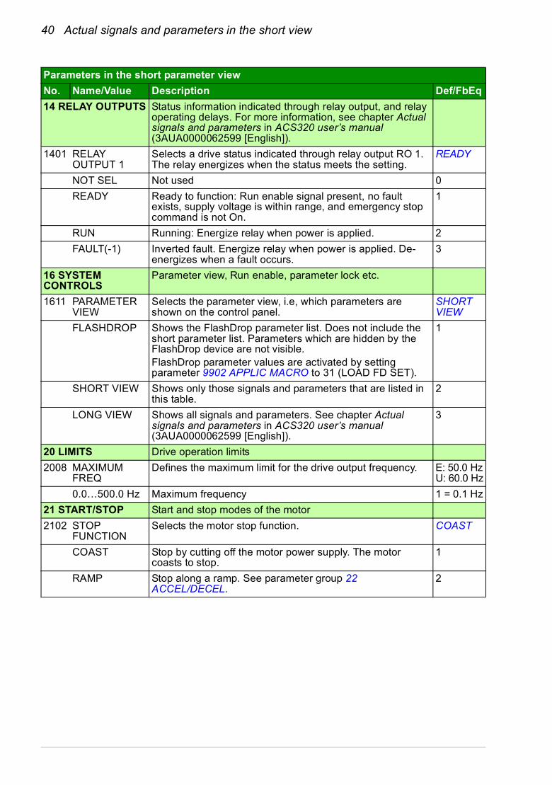
14 RELAY OUTPUTS Status information indicated through relay output, and relay operating delays. For more information, see chapter Actual signals and parameters in ACS320 user’s manual (3AUA0000062599 [English]).
1401 RELAY OUTPUT 1
Selects a drive status indicated through relay output RO 1. The relay energizes when the status meets the setting.
READY
NOT SEL Not used 0
READY Ready to function: Run enable signal present, no fault exists, supply voltage is within range, and emergency stop command is not On.
1
RUN Running: Energize relay when power is applied. 2
FAULT(-1) Inverted fault. Energize relay when power is applied. De-energizes when a fault occurs.
3
16 SYSTEM CONTROLS
Parameter view, Run enable, parameter lock etc.
1611 PARAMETER VIEW
Selects the parameter view, i.e, which parameters are shown on the control panel.
SHORT VIEW
FLASHDROP Shows the FlashDrop parameter list. Does not include the short parameter list. Parameters which are hidden by the FlashDrop device are not visible.FlashDrop parameter values are activated by setting parameter 9902 APPLIC MACRO to 31 (LOAD FD SET).
1
SHORT VIEW Shows only those signals and parameters that are listed in this table.
2
LONG VIEW Shows all signals and parameters. See chapter Actual signals and parameters in ACS320 user’s manual (3AUA0000062599 [English]).
3
20 LIMITS Drive operation limits
2008 MAXIMUM FREQ
Defines the maximum limit for the drive output frequency. E: 50.0 HzU: 60.0 Hz
0.0…500.0 Hz Maximum frequency 1 = 0.1 Hz
21 START/STOP Start and stop modes of the motor
2102 STOP FUNCTION
Selects the motor stop function. COAST
COAST Stop by cutting off the motor power supply. The motor coasts to stop.
1
RAMP Stop along a ramp. See parameter group 22 ACCEL/DECEL.
2
Parameters in the short parameter view
No. Name/Value Description Def/FbEq
Actual signals and parameters in the short view 41
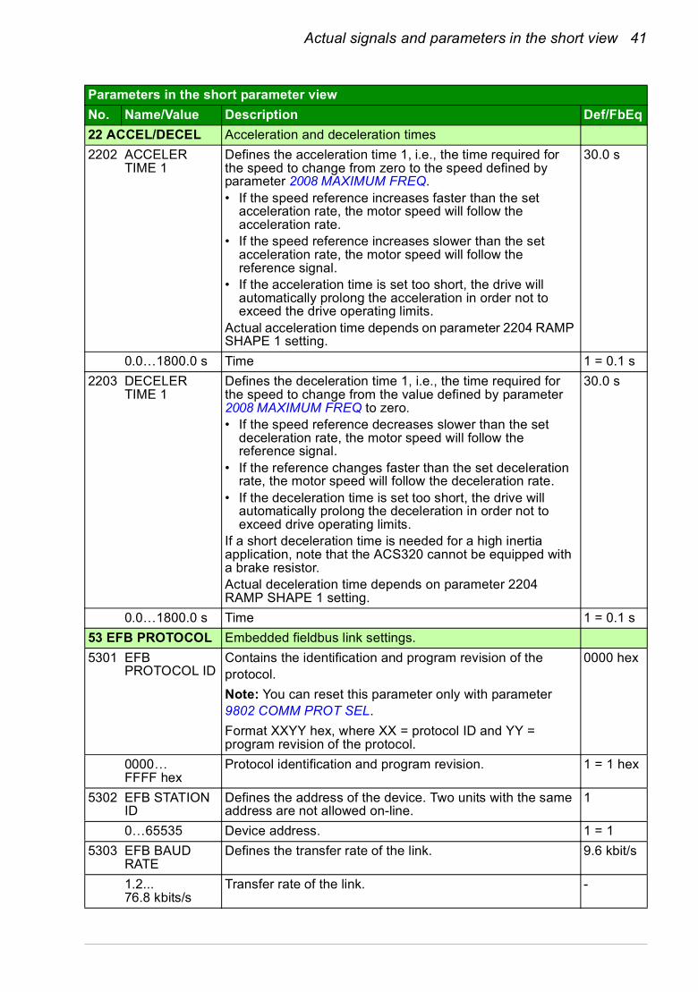
22 ACCEL/DECEL Acceleration and deceleration times
2202 ACCELER TIME 1
Defines the acceleration time 1, i.e., the time required for the speed to change from zero to the speed defined by parameter 2008 MAXIMUM FREQ.• If the speed reference increases faster than the set
acceleration rate, the motor speed will follow the acceleration rate.
• If the speed reference increases slower than the set acceleration rate, the motor speed will follow the reference signal.
• If the acceleration time is set too short, the drive will automatically prolong the acceleration in order not to exceed the drive operating limits.
Actual acceleration time depends on parameter 2204 RAMP SHAPE 1 setting.
30.0 s
0.0…1800.0 s Time 1 = 0.1 s
2203 DECELER TIME 1
Defines the deceleration time 1, i.e., the time required for the speed to change from the value defined by parameter 2008 MAXIMUM FREQ to zero.• If the speed reference decreases slower than the set
deceleration rate, the motor speed will follow the reference signal.
• If the reference changes faster than the set deceleration rate, the motor speed will follow the deceleration rate.
• If the deceleration time is set too short, the drive will automatically prolong the deceleration in order not to exceed drive operating limits.
If a short deceleration time is needed for a high inertia application, note that the ACS320 cannot be equipped with a brake resistor. Actual deceleration time depends on parameter 2204 RAMP SHAPE 1 setting.
30.0 s
0.0…1800.0 s Time 1 = 0.1 s
53 EFB PROTOCOL Embedded fieldbus link settings.
5301 EFB PROTOCOL ID
Contains the identification and program revision of the protocol.
Note: You can reset this parameter only with parameter 9802 COMM PROT SEL.
Format XXYY hex, where XX = protocol ID and YY = program revision of the protocol.
0000 hex
0000…FFFF hex
Protocol identification and program revision. 1 = 1 hex
5302 EFB STATION ID
Defines the address of the device. Two units with the same address are not allowed on-line.
1
0…65535 Device address. 1 = 1
5303 EFB BAUD RATE
Defines the transfer rate of the link. 9.6 kbit/s
1.2...76.8 kbits/s
Transfer rate of the link. -
Parameters in the short parameter view
No. Name/Value Description Def/FbEq
42 Actual signals and parameters in the short view
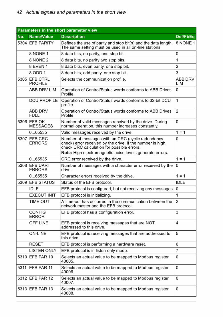
5304 EFB PARITY Defines the use of parity and stop bit(s) and the data length. The same setting must be used in all on-line stations.
8 NONE 1
8 NONE 1 8 data bits, no parity, one stop bit. 0
8 NONE 2 8 data bits, no parity two stop bits. 1
8 EVEN 1 8 data bits, even parity, one stop bit. 2
8 ODD 1 8 data bits, odd parity, one stop bit. 3
5305 EFB CTRL PROFILE
Selects the communication profile. ABB DRV LIM
ABB DRV LIM Operation of Control/Status words conforms to ABB Drives Profile.
0
DCU PROFILE Operation of Control/Status words conforms to 32-bit DCU profile.
1
ABB DRV FULL
Operation of Control/Status words conforms to ABB Drives Profile.
2
5306 EFB OK MESSAGES
Number of valid messages received by the drive. During normal operation, this number increases constantly.
0
0...65535 Valid messages received by the drive. 1 = 1
5307 EFB CRC ERRORS
Number of messages with an CRC (cyclic redundancy check) error received by the drive. If the number is high, check CRC calculation for possible errors.Note: High electromagnetic noise levels generate errors.
0
0...65535 CRC error received by the drive. 1 = 1
5308 EFB UART ERRORS
Number of messages with a character error received by the drive.
0
0...65535 Character errors received by the drive. 1 = 1
5309 EFB STATUS Status of the EFB protocol. IDLE
IDLE EFB protocol is configured, but not receiving any messages. 0
EXECUT INIT EFB protocol is initializing. 1
TIME OUT A time-out has occurred in the communication between the network master and the EFB protocol.
2
CONFIG ERROR
EFB protocol has a configuration error. 3
OFF LINE EFB protocol is receiving messages that are NOT addressed to this drive.
4
ON-LINE EFB protocol is receiving messages that are addressed to this drive.
5
RESET EFB protocol is performing a hardware reset. 6
LISTEN ONLY EFB protocol is in listen-only mode. 7
5310 EFB PAR 10 Selects an actual value to be mapped to Modbus register 40005.
0
5311 EFB PAR 11 Selects an actual value to be mapped to Modbus register 40006.
0
5312 EFB PAR 12 Selects an actual value to be mapped to Modbus register 40007.
0
5313 EFB PAR 13 Selects an actual value to be mapped to Modbus register 40008.
0
Parameters in the short parameter view
No. Name/Value Description Def/FbEq
Actual signals and parameters in the short view 43
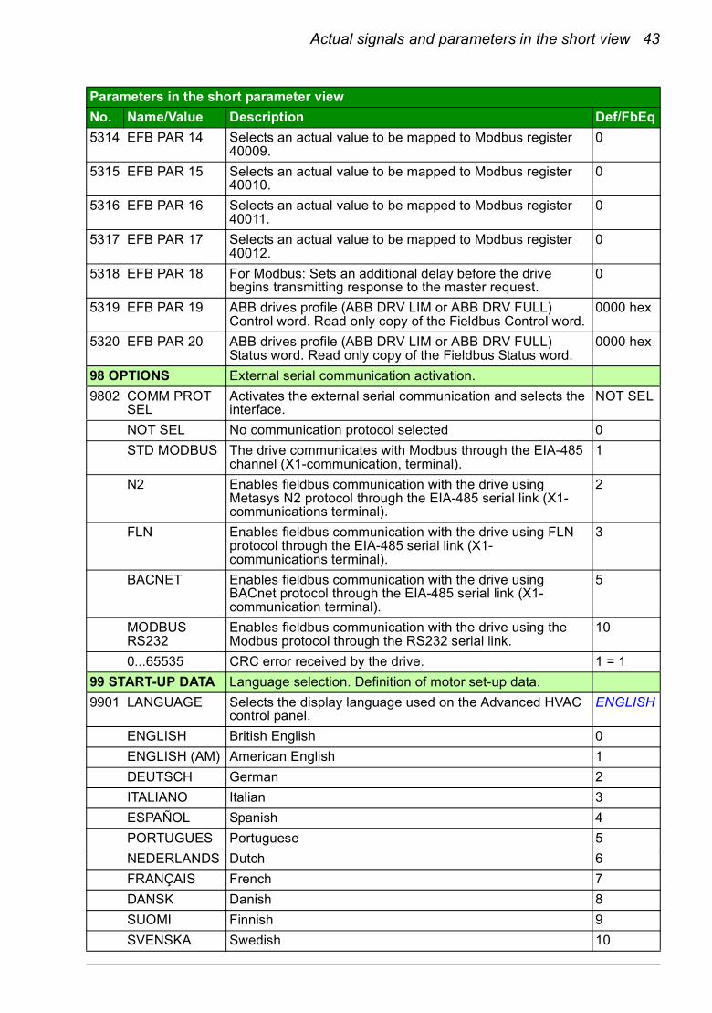
5314 EFB PAR 14 Selects an actual value to be mapped to Modbus register 40009.
0
5315 EFB PAR 15 Selects an actual value to be mapped to Modbus register 40010.
0
5316 EFB PAR 16 Selects an actual value to be mapped to Modbus register 40011.
0
5317 EFB PAR 17 Selects an actual value to be mapped to Modbus register 40012.
0
5318 EFB PAR 18 For Modbus: Sets an additional delay before the drive begins transmitting response to the master request.
0
5319 EFB PAR 19 ABB drives profile (ABB DRV LIM or ABB DRV FULL) Control word. Read only copy of the Fieldbus Control word.
0000 hex
5320 EFB PAR 20 ABB drives profile (ABB DRV LIM or ABB DRV FULL) Status word. Read only copy of the Fieldbus Status word.
0000 hex
98 OPTIONS External serial communication activation.
9802 COMM PROT SEL
Activates the external serial communication and selects the interface.
NOT SEL
NOT SEL No communication protocol selected 0
STD MODBUS The drive communicates with Modbus through the EIA-485 channel (X1-communication, terminal).
1
N2 Enables fieldbus communication with the drive using Metasys N2 protocol through the EIA-485 serial link (X1-communications terminal).
2
FLN Enables fieldbus communication with the drive using FLN protocol through the EIA-485 serial link (X1-communications terminal).
3
BACNET Enables fieldbus communication with the drive using BACnet protocol through the EIA-485 serial link (X1-communication terminal).
5
MODBUS RS232
Enables fieldbus communication with the drive using the Modbus protocol through the RS232 serial link.
10
0...65535 CRC error received by the drive. 1 = 1
99 START-UP DATA Language selection. Definition of motor set-up data.
9901 LANGUAGE Selects the display language used on the Advanced HVAC control panel.
ENGLISH
ENGLISH British English 0
ENGLISH (AM) American English 1
DEUTSCH German 2
ITALIANO Italian 3
ESPAÑOL Spanish 4
PORTUGUES Portuguese 5
NEDERLANDS Dutch 6
FRANÇAIS French 7
DANSK Danish 8
SUOMI Finnish 9
SVENSKA Swedish 10
Parameters in the short parameter view
No. Name/Value Description Def/FbEq
44 Actual signals and parameters in the short view
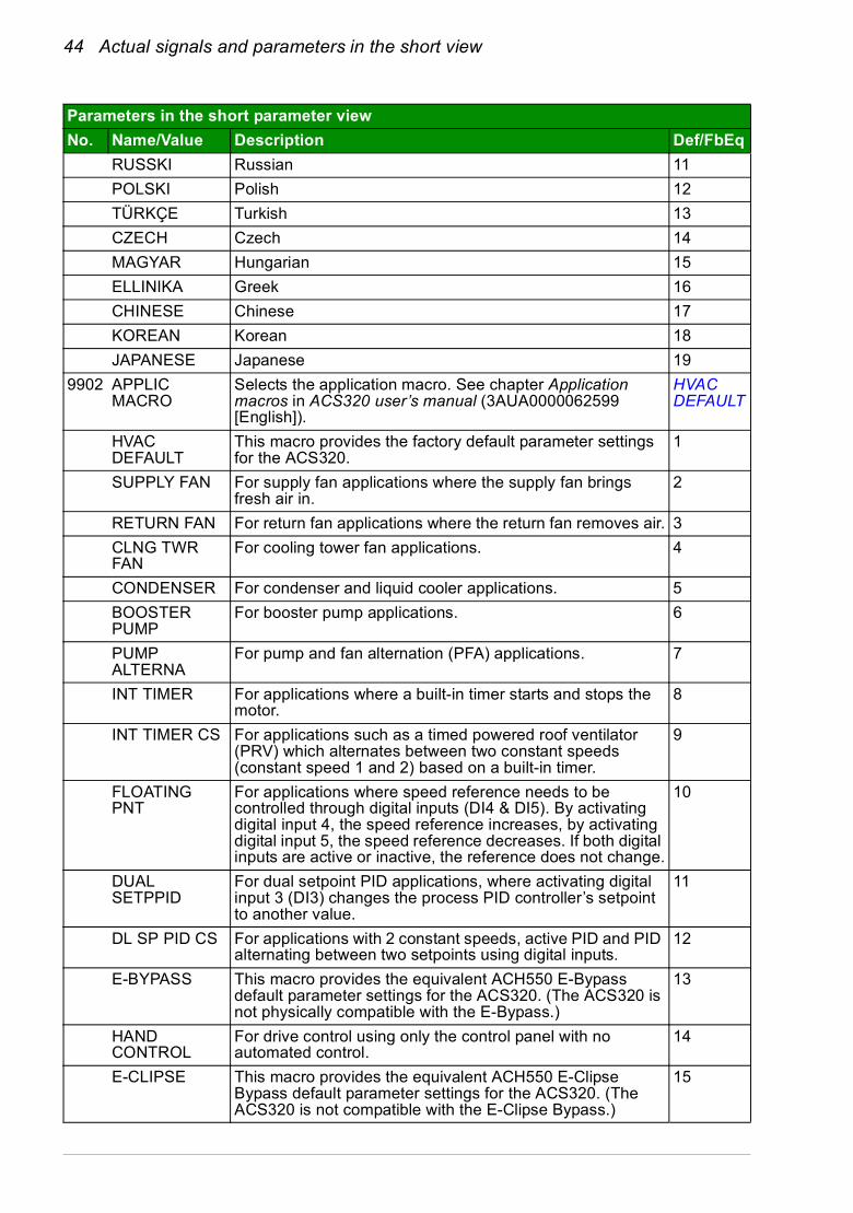
RUSSKI Russian 11
POLSKI Polish 12
TÜRKÇE Turkish 13
CZECH Czech 14
MAGYAR Hungarian 15
ELLINIKA Greek 16
CHINESE Chinese 17
KOREAN Korean 18
JAPANESE Japanese 19
9902 APPLIC MACRO
Selects the application macro. See chapter Application macros in ACS320 user’s manual (3AUA0000062599 [English]).
HVAC DEFAULT
HVAC DEFAULT
This macro provides the factory default parameter settings for the ACS320.
1
SUPPLY FAN For supply fan applications where the supply fan brings fresh air in.
2
RETURN FAN For return fan applications where the return fan removes air. 3
CLNG TWR FAN
For cooling tower fan applications. 4
CONDENSER For condenser and liquid cooler applications. 5
BOOSTER PUMP
For booster pump applications. 6
PUMP ALTERNA
For pump and fan alternation (PFA) applications. 7
INT TIMER For applications where a built-in timer starts and stops the motor.
8
INT TIMER CS For applications such as a timed powered roof ventilator (PRV) which alternates between two constant speeds (constant speed 1 and 2) based on a built-in timer.
9
FLOATING PNT
For applications where speed reference needs to be controlled through digital inputs (DI4 & DI5). By activating digital input 4, the speed reference increases, by activating digital input 5, the speed reference decreases. If both digital inputs are active or inactive, the reference does not change.
10
DUAL SETPPID
For dual setpoint PID applications, where activating digital input 3 (DI3) changes the process PID controller’s setpoint to another value.
11
DL SP PID CS For applications with 2 constant speeds, active PID and PID alternating between two setpoints using digital inputs.
12
E-BYPASS This macro provides the equivalent ACH550 E-Bypass default parameter settings for the ACS320. (The ACS320 is not physically compatible with the E-Bypass.)
13
HAND CONTROL
For drive control using only the control panel with no automated control.
14
E-CLIPSE This macro provides the equivalent ACH550 E-Clipse Bypass default parameter settings for the ACS320. (The ACS320 is not compatible with the E-Clipse Bypass.)
15
Parameters in the short parameter view
No. Name/Value Description Def/FbEq
Actual signals and parameters in the short view 45
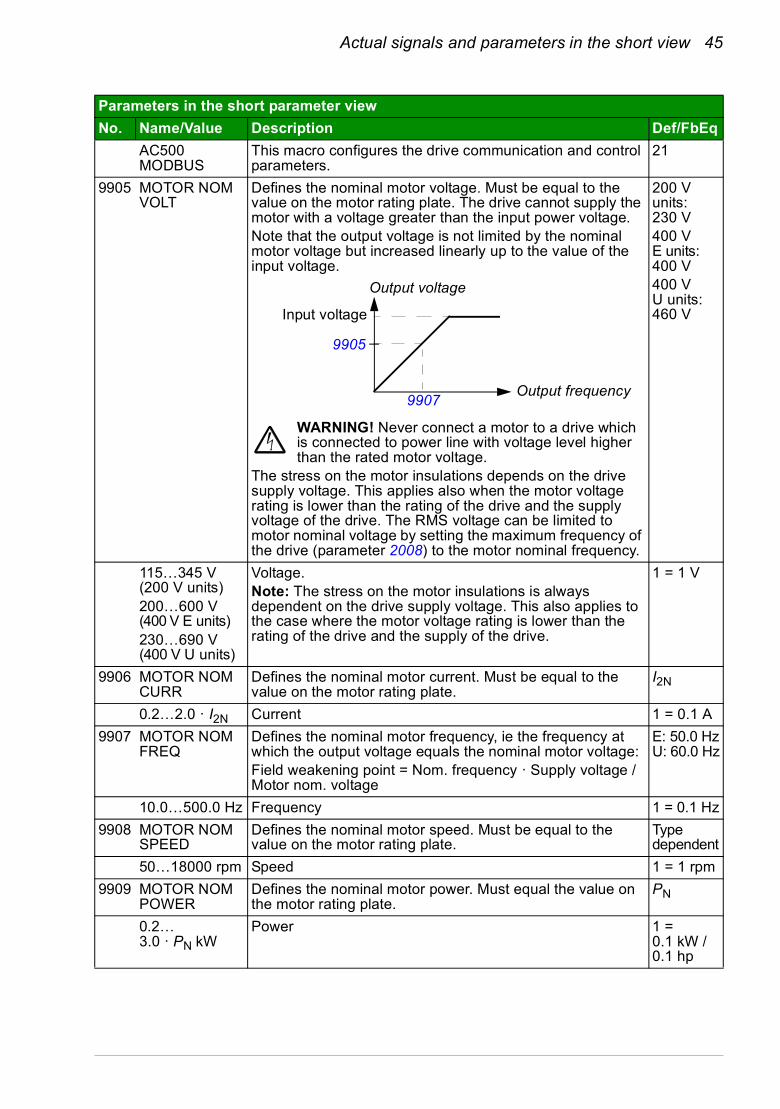
AC500 MODBUS
This macro configures the drive communication and control parameters.
21
9905 MOTOR NOM VOLT
Defines the nominal motor voltage. Must be equal to the value on the motor rating plate. The drive cannot supply the motor with a voltage greater than the input power voltage.Note that the output voltage is not limited by the nominal motor voltage but increased linearly up to the value of the input voltage.
WARNING! Never connect a motor to a drive which is connected to power line with voltage level higher than the rated motor voltage.
The stress on the motor insulations depends on the drive supply voltage. This applies also when the motor voltage rating is lower than the rating of the drive and the supply voltage of the drive. The RMS voltage can be limited to motor nominal voltage by setting the maximum frequency of the drive (parameter 2008) to the motor nominal frequency.
200 V units:230 V 400 VE units:400 V400 V U units:460 V
115…345 V (200 V units)200…600 V (400 V E units)230…690 V (400 V U units)
Voltage.Note: The stress on the motor insulations is always dependent on the drive supply voltage. This also applies to the case where the motor voltage rating is lower than the rating of the drive and the supply of the drive.
1 = 1 V
9906 MOTOR NOM CURR
Defines the nominal motor current. Must be equal to the value on the motor rating plate.
I2N
0.2…2.0 · I2N Current 1 = 0.1 A
9907 MOTOR NOM FREQ
Defines the nominal motor frequency, ie the frequency at which the output voltage equals the nominal motor voltage: Field weakening point = Nom. frequency · Supply voltage / Motor nom. voltage
E: 50.0 HzU: 60.0 Hz
10.0…500.0 Hz Frequency 1 = 0.1 Hz
9908 MOTOR NOM SPEED
Defines the nominal motor speed. Must be equal to the value on the motor rating plate.
Type dependent
50…18000 rpm Speed 1 = 1 rpm
9909 MOTOR NOM POWER
Defines the nominal motor power. Must equal the value on the motor rating plate.
PN
0.2…3.0 · PN kW
Power 1 = 0.1 kW / 0.1 hp
Parameters in the short parameter view
No. Name/Value Description Def/FbEq
Output voltage
Output frequency
Input voltage
9907
9905

46 Actual signals and parameters in the short view
Technical data 47
7. Technical data
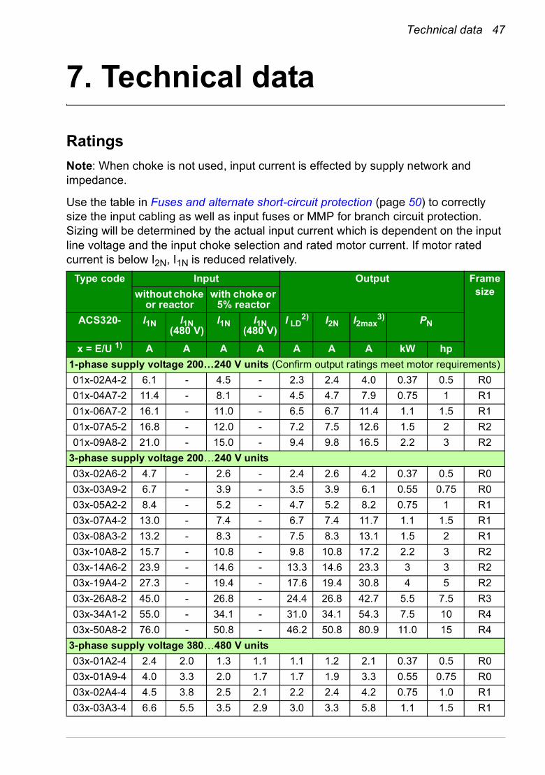
Ratings
Note: When choke is not used, input current is effected by supply network and impedance.
Use the table in Fuses and alternate short-circuit protection (page 50) to correctly size the input cabling as well as input fuses or MMP for branch circuit protection. Sizing will be determined by the actual input current which is dependent on the input line voltage and the input choke selection and rated motor current. If motor rated current is below I2N, I1N is reduced relatively.
Type code Input Output Framesizewithout choke
or reactorwith choke or
5% reactor
ACS320- I1N I1N (480 V)
I1N I1N (480 V)
I LD2) I2N I2max
3) PN
x = E/U 1) A A A A A A A kW hp
1-phase supply voltage 200…240 V units (Confirm output ratings meet motor requirements)
01x-02A4-2 6.1 - 4.5 - 2.3 2.4 4.0 0.37 0.5 R0
01x-04A7-2 11.4 - 8.1 - 4.5 4.7 7.9 0.75 1 R1
01x-06A7-2 16.1 - 11.0 - 6.5 6.7 11.4 1.1 1.5 R1
01x-07A5-2 16.8 - 12.0 - 7.2 7.5 12.6 1.5 2 R2
01x-09A8-2 21.0 - 15.0 - 9.4 9.8 16.5 2.2 3 R2
3-phase supply voltage 200…240 V units
03x-02A6-2 4.7 - 2.6 - 2.4 2.6 4.2 0.37 0.5 R0
03x-03A9-2 6.7 - 3.9 - 3.5 3.9 6.1 0.55 0.75 R0
03x-05A2-2 8.4 - 5.2 - 4.7 5.2 8.2 0.75 1 R1
03x-07A4-2 13.0 - 7.4 - 6.7 7.4 11.7 1.1 1.5 R1
03x-08A3-2 13.2 - 8.3 - 7.5 8.3 13.1 1.5 2 R1
03x-10A8-2 15.7 - 10.8 - 9.8 10.8 17.2 2.2 3 R2
03x-14A6-2 23.9 - 14.6 - 13.3 14.6 23.3 3 3 R2
03x-19A4-2 27.3 - 19.4 - 17.6 19.4 30.8 4 5 R2
03x-26A8-2 45.0 - 26.8 - 24.4 26.8 42.7 5.5 7.5 R3
03x-34A1-2 55.0 - 34.1 - 31.0 34.1 54.3 7.5 10 R4
03x-50A8-2 76.0 - 50.8 - 46.2 50.8 80.9 11.0 15 R4
3-phase supply voltage 380…480 V units
03x-01A2-4 2.4 2.0 1.3 1.1 1.1 1.2 2.1 0.37 0.5 R0
03x-01A9-4 4.0 3.3 2.0 1.7 1.7 1.9 3.3 0.55 0.75 R0
03x-02A4-4 4.5 3.8 2.5 2.1 2.2 2.4 4.2 0.75 1.0 R1
03x-03A3-4 6.6 5.5 3.5 2.9 3.0 3.3 5.8 1.1 1.5 R1
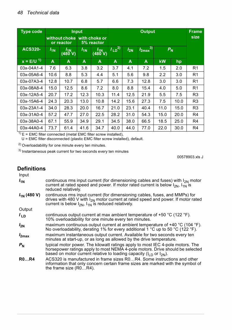
48 Technical data
Definitions
03x-04A1-4 7.6 6.3 3.8 3.2 3.7 4.1 7.2 1.5 2.0 R1
03x-05A6-4 10.6 8.8 5.3 4.4 5.1 5.6 9.8 2.2 3.0 R1
03x-07A3-4 12.8 10.7 6.8 5.7 6.6 7.3 12.8 3.0 3.0 R1
03x-08A8-4 15.0 12.5 8.6 7.2 8.0 8.8 15.4 4.0 5.0 R1
03x-12A5-4 20.7 17.2 12.3 10.3 11.4 12.5 21.9 5.5 7.5 R3
03x-15A6-4 24.3 20.3 13.0 10.8 14.2 15.6 27.3 7.5 10.0 R3
03x-23A1-4 34.0 28.3 20.0 16.7 21.0 23.1 40.4 11.0 15.0 R3
03x-31A0-4 57.2 47.7 27.0 22.5 28.2 31.0 54.3 15.0 20.0 R4
03x-38A0-4 67.1 55.9 34.9 29.1 34.5 38.0 66.5 18.5 25.0 R4
03x-44A0-4 73.7 61.4 41.6 34.7 40.0 44.0 77.0 22.0 30.0 R41) E = EMC filter connected (metal EMC filter screw installed), U = EMC filter disconnected (plastic EMC filter screw installed), default.2) Overloadability for one minute every ten minutes.3) Instantaneous peak current for two seconds every ten minutes
00578903.xls J
InputI1N continuous rms input current (for dimensioning cables and fuses) with I2N motor
current at rated speed and power. If motor rated current is below I2N, I1N is reduced relatively.
I1N (480 V) continuous rms input current (for dimensioning cables, fuses, and MMPs) for drives with 480 V with I2N motor current at rated speed and power. If motor rated current is below I2N, I1N is reduced relatively.
OutputI LD continuous output current at max ambient temperature of +50 °C (122 °F).
10% overloadability for one minute every ten minutes.I2N maximum continuous output current at ambient temperature of +40 °C (104 °F).
No overloadability, derating 1% for every additional 1 °C up to 50 °C (122 °F).I2max maximum instantaneous output current. Available for two seconds every ten
minutes at start-up, or as long as allowed by the drive temperature.PN typical motor power. The kilowatt ratings apply to most IEC 4-pole motors. The
horsepower ratings apply to most NEMA 4-pole motors. Drive should be selected based on motor current relative to loading capacity (ILD or I2N).
R0…R4 ACS320 is manufactured in frame sizes R0…R4. Some instructions and other information that only concern certain frame sizes are marked with the symbol of the frame size (R0…R4).
Type code Input Output Framesizewithout choke
or reactorwith choke or
5% reactor
ACS320- I1N I1N (480 V)
I1N I1N (480 V)
I LD2) I2N I2max
3) PN
x = E/U 1) A A A A A A A kW hp
Technical data 49
Sizing
Drive sizing is based on the rated motor current and power. To achieve the rated motor power given in the table, the rated current of the drive must be higher than or equal to the rated motor current. The rated power of the drive must also be higher than or equal to compared to the rated motor power. The power ratings are the same regardless of the supply voltage within one voltage range.
In multimotor systems, the drive output current rating ILD must be equal to or greater than the calculated sum of the input currents of all motors.
Note:
• The maximum allowed motor shaft power is limited to 1.5 · PN. If the limit exceeds, motor torque and current are automatically restricted. The function protects the input bridge of the drive against overload.
• The ratings apply at ambient temperature of 40 °C (104 °F) for I2N and 50 °C (122 °F) for ILD.
Derating
For information on derating, see chapter Technical data, section Derating in ACS320 user’s manual (3AUA0000062599 [English]).
50 Technical data
Fuses and alternate short-circuit protection
Fuses
The rated fuse currents given in the table are the maximums for the mentioned fuse types. If smaller fuse ratings are used, check that the fuse rms current rating is larger than the rated I1N current given in the Ratings table on page 47. If 150% of output power is needed, multiply current I1N by 1.5.
Check that the operating time of the fuse is below 0.5 seconds. The operating time depends on the fuse type, the supply network impedance as well as the cross-sectional area, material and length of the supply cable. In case the 0.5 seconds operating time is exceeded with the gG or T fuses, ultra rapid (aR) fuses reduces in most cases the operating time to an acceptable level.
Note:
• Do not use larger fuses when the input power cable is selected according to this table.
• Choose the correct fuse size according to the actual input current which depends on the input line voltage and the input choke selection.
• You can use other fuse types if they meet the current rating of the fuse in the table and also if the melting curve of the other fuses does not exceed the melting curve of the fuse in the table.
Alternate short-circuit protection
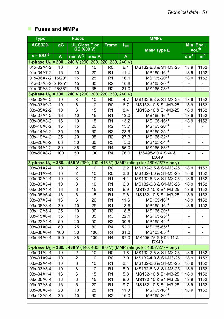
In accordance with the National Electrical Code (NEC), the following ABB type E manual motor protectors can be used as an alternate to the recommended fuses as a means of branch circuit protection:
• MS132-x.x and S1-M3-25
• MS495-xx or MS495-xxE and SK4-11 & DX49
• MS165-xx.
When the correct ABB type E manual motor protector is selected from the table and used for branch circuit protection, the drive is suitable for use in a circuit capable of delivering not more than 65 kA RMS symmetrical amperes at the drive maximum rated voltage. See the appropriate ratings in the following table.
IP20 open type and IP21 UL type 1 ACS320 can use ABB type E manual motor protectors for branch circuit protection. See the MMP rating table for the minimum enclosure volume of IP20 open type ACS320 mounted in an enclosure.
Technical data 51
Fuses and MMPs
Type Fuses MMPs
ACS320- gG UL Class T or CC (600 V)
Frame I1NMMP Type E
Min. Encl.Vol.4)
x = E/U1) A min A2) max A A dm3 in3
1-phase UN = 200…240 V (200, 208, 220, 230, 240 V)01x-02A4-2 10 6 10 R0 6.1 MS132-6.3 & S1-M3-25 18.9 115201x-04A7-2 16 10 20 R1 11.4 MS165-163) 18.9 115201x-06A7-2 16/20* 15 25 R1 16.1 MS165-203) 18.9 115201x-07A5-2 20/25* 15 30 R2 16.8 MS165-203) - -01x-09A8-2 25/35* 15 35 R2 21.0 MS165-253) - -3-phase UN = 200…240 V (200, 208, 220, 230, 240 V)03x-02A6-2 10 3 10 R0 4.7 MS132-6.3 & S1-M3-25 18.9 115203x-03A9-2 10 6 10 R0 6.7 MS132-10 & S1-M3-25 18.9 115203x-05A2-2 10 6 15 R1 8.4 MS132-10 & S1-M3-25 18.9 115203x-07A4-2 16 10 15 R1 13.0 MS165-163) 18.9 115203x-08A3-2 16 10 15 R1 13.2 MS165-163) 18.9 115203x-10A8-2 16 15 20 R2 15.7 MS165-203) - -03x-14A6-2 25 15 30 R2 23.9 MS165-253) - -03x-19A4-2 25 20 35 R2 27.3 MS165-323) - -03x-26A8-2 63 30 60 R3 45.0 MS165-543) - -03x-34A1-2 80 35 80 R4 55.0 MS165-653) - -03x-50A8-2 100 50 100 R4 76.0 MS495-90 & SK4 &
DX49- -
3-phase UN = 380... 480 V (380, 400, 415 V) (MMP ratings for 480Y/277V only)03x-01A2-4 10 2 10 R0 2.2 MS132-2.5 & S1-M3-25 18.9 115203x-01A9-4 10 2 10 R0 3.6 MS132-4.0 & S1-M3-25 18.9 115203x-02A4-4 10 3 10 R1 4.1 MS132-6.3 & S1-M3-25 18.9 115203x-03A3-4 10 3 10 R1 6.0 MS132-6.3 & S1-M3-25 18.9 115203x-04A1-4 16 6 15 R1 6.9 MS132-10 & S1-M3-25 18.9 115203x-05A6-4 16 6 15 R1 9.6 MS132-10 & S1-M3-25 18.9 115203x-07A3-4 16 6 20 R1 11.6 MS165-163) 18.9 115203x-08A8-4 20 10 25 R1 13.6 MS165-163) 18.9 115203x-12A5-4 25 10 30 R3 18.8 MS165-203) - -03x-15A6-4 35 15 35 R3 22.1 MS165-253) - -03x-23A1-4 50 20 50 R3 30.9 MS165-423) - -03x-31A0-4 80 25 80 R4 52.0 MS165-653) - -03x-38A0-4 100 30 100 R4 61.0 MS165-653) - -03x-44A0-4 100 35 100 R4 67.0 MS495-75 & SK4-11 &
DX49- -
3-phase UN = 380... 480 V (440, 460, 480 V) (MMP ratings for 480Y/277V only)03x-01A2-4 10 2 10 R0 1.8 MS132-2.5 & S1-M3-25 18.9 115203x-01A9-4 10 2 10 R0 3.0 MS132-4.0 & S1-M3-25 18.9 115203x-02A4-4 10 3 10 R1 3.4 MS132-6.3 & S1-M3-25 18.9 115203x-03A3-4 10 3 10 R1 5.0 MS132-6.3 & S1-M3-25 18.9 115203x-04A1-4 16 6 15 R1 5.8 MS132-10 & S1-M3-25 18.9 115203x-05A6-4 16 6 15 R1 8.0 MS132-10 & S1-M3-25 18.9 115203x-07A3-4 16 6 20 R1 9.7 MS132-10 & S1-M3-25 18.9 115203x-08A8-4 20 10 25 R1 11.0 MS165-163) 18.9 115203x-12A5-4 25 10 30 R3 16.0 MS165-203) - -

52 Technical data
03x-15A6-4 35 15 35 R3 18.0 MS165-203) - -03x-23A1-4 50 20 50 R3 26.0 MS165-323) - -03x-31A0-4 80 25 80 R4 43.0 MS165-543) - -03x-38A0-4 100 30 100 R4 51.0 MS165-653) - -03x-44A0-4 100 35 100 R4 56.0 MS165-653) - -
00578903.xls.J1) E = EMC filter connected (metal EMC filter screw installed),
U = EMC filter disconnected (plastic EMC filter screw installed), U.S parameterization.2) minimum fuse size can be used with input choke according to table in Rating section3) Trip class 10; integral trip indication; does not require additional line-side feeder terminal.4) For all drives, the enclosure must be sized to accommodate the specific thermal considerations of the applications as well as provide free space for cooling. See ACS320 user’s manual, chapter Technical data, section Free space requirements.For UL only: The minimum enclosure volume is specified in the UL listing for drive frames R0 and R1 when applied with the ABB type E MMP shown in the table. ACS320 drives are intended to be mounted in an
Type Fuses MMPs
ACS320- gG UL Class T or CC (600 V)
Frame I1NMMP Type E
Min. Encl.Vol.4)
x = E/U1) A min A2) max A A dm3 in3

Technical data 53
UL marking
See the type designation label for the valid markings of your drive.
The UL mark is attached to the drive to verify that it meets UL requirements.
UL checklist
See the instructions for electrical installation in the sections in this manual or in the ACS320 user’s manual (3AUA0000062599 [English]0 specified below.
Input power connection – See ACS320 user’s manual, chapter Technical data, section Electrical power network specification.
Disconnecting device (disconnecting means) – See ACS320 user’s manual, chapter Planning the electrical installation, section Selecting the supply disconnecting device (disconnecting means).
Ambient conditions – The drives are to be used in a heated indoor controlled environment. See ACS320 user’s manual, chapter Technical data, section Ambient conditions for specific limits.
Input cable fuses – For installation in the United States, branch circuit protection must be provided in accordance with the National Electrical Code (NEC) and any applicable local codes. To fulfill this requirement, use the UL classified fuses given in section Fuses and MMPs on page 51.
For installation in Canada, branch circuit protection must be provided in accordance with Canadian Electrical Code and any applicable provincial codes. To fulfill this requirement, use the UL classified fuses given in section Fuses and MMPs on page 51.
Power cable selection – See ACS320 user’s manual, chapter Planning the electrical installation, section Selecting the power cables.
Power cable connections – For the connection diagram and tightening torques, see section Connecting the power cables on page 19.
Overload protection – The drive provides overload protection in accordance with the National Electrical Code (US).

54 Technical data

Technical data 55

56 Technical data

Further information
Product and service inquiries
Address any inquiries about the product to your local ABB representative, quoting the type designation and serial number of the unit in question. A listing of ABB sales, support and service contacts can be found by navigating to www.abb.com/searchchannels.
Product training
For information on ABB product training, navigate to new.abb.com/service/training.
Providing feedback on ABB Drives manuals
Your comments on our manuals are welcome. Navigate to new.abb.com/drives/manuals-feedback-form.
Document library on the Internet
You can find manuals and other product documents in PDF format on the Internet at www.abb.com/drives/documents..

www.abb.com/driveswww.abb.com/drivespartners
Contact us
3AUA0000086933 Rev D (EN) EFFECTIVE: 2016-08-18
3AUA0000086933D