tilting-pad geometry journal bearings (tiltbr) · hydrodynamic, hydrostatic, and hybrid lubricated...
TRANSCRIPT
AdvancedRotatingMachineryDynamics
TILTBRTILTBRVersion
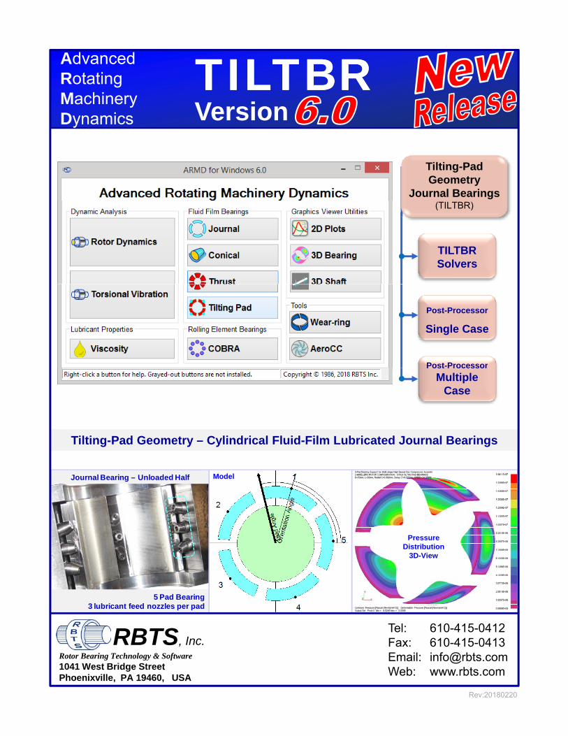
Tilting-Pad Geometry
Journal Bearings
Dynamics Version
(TILTBR)
TILTBRSolvers
Post-Processor
Post-Processor
Single Case
Post Processor
Multiple Case
Tilting-Pad Geometry – Cylindrical Fluid-Film Lubricated Journal Bearings
Journal Bearing – Unloaded Half
P
Model
5 Pad Bearing3 lubricant feed nozzles per pad
PressureDistribution
3D-View
Tel: 610-415-0412Fax: 610-415-0413Email: [email protected]: www.rbts.com
Rotor Bearing Technology & Software1041 West Bridge StreetPhoenixville, PA 19460, USA
RBTS, Inc.
Rev:20180220
The Worldwide Leader in Software for Rotating Machinery Dynamics
ARMDV6.0
ARMDV6.0 TILTBRTILTBR
TM Fluid-Film
Bearing
M o d u l e
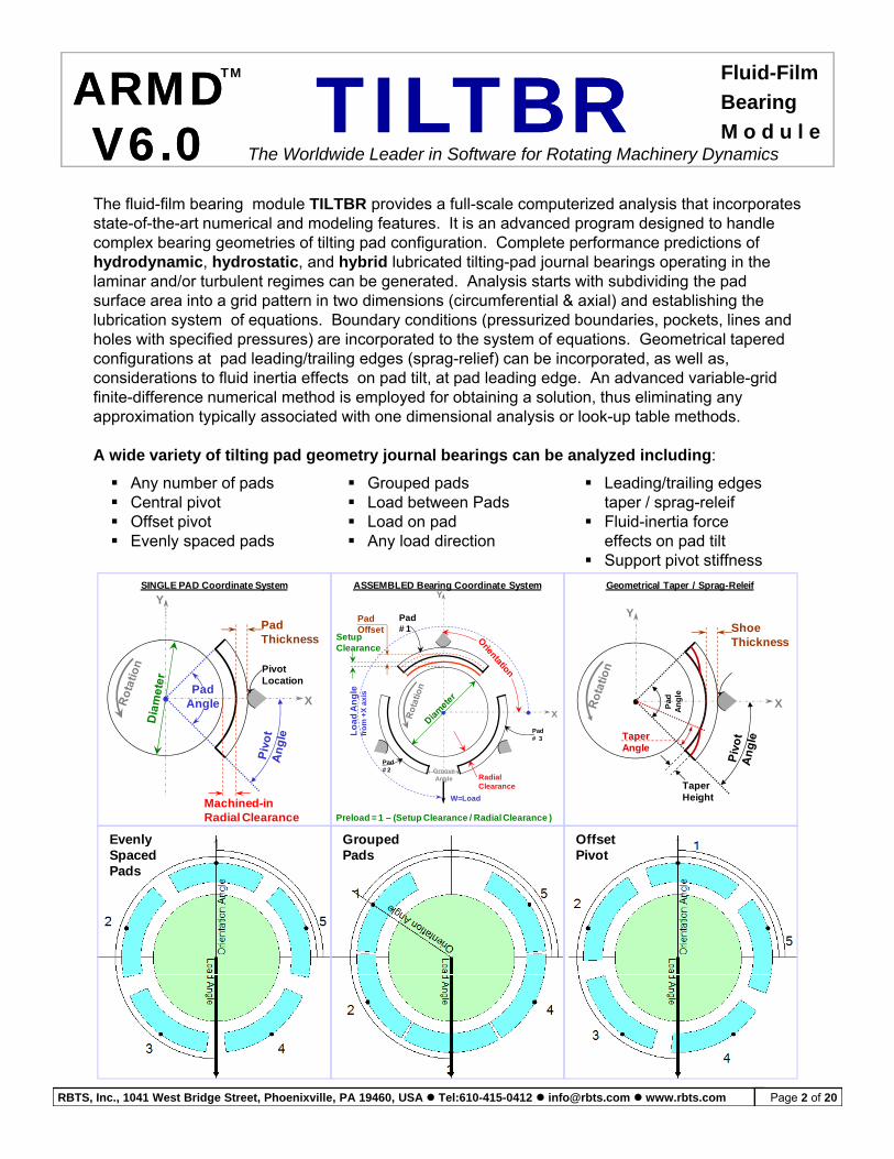
The fluid-film bearing module TILTBR provides a full-scale computerized analysis that incorporates state-of-the-art numerical and modeling features. It is an advanced program designed to handle complex bearing geometries of tilting pad configuration. Complete performance predictions of hydrodynamic, hydrostatic, and hybrid lubricated tilting-pad journal bearings operating in the laminar and/or turbulent regimes can be generated. Analysis starts with subdividing the pad surface area into a grid pattern in two dimensions (circumferential & axial) and establishing the l b i ti t f ti B d diti ( i d b d i k t li dlubrication system of equations. Boundary conditions (pressurized boundaries, pockets, lines and holes with specified pressures) are incorporated to the system of equations. Geometrical tapered configurations at pad leading/trailing edges (sprag-relief) can be incorporated, as well as, considerations to fluid inertia effects on pad tilt, at pad leading edge. An advanced variable-grid finite-difference numerical method is employed for obtaining a solution, thus eliminating any approximation typically associated with one dimensional analysis or look-up table methods.
A wide variety of tilting pad geometry journal bearings can be analyzed including:
Any number of pads Central pivot Offset pivot Evenly spaced pads
Grouped pads Load between Pads Load on pad Any load direction
Leading/trailing edges taper / sprag-releif
Fluid-inertia force effects on pad tilt
Support pivot stiffness
X
Y
Pad
An
gle
PivotLocation
ShoeThickness
SINGLE PAD Coordinate System
XPad
Angle
PivotLocation
PadThickness
YASSEMBLED Bearing Coordinate System
X
Y
Pad# 1
An
gle
X a
xis
PadOffset
SetupClearance
Geometrical Taper / Sprag-Releif
A
Taper Height
Taper Angle
Taper HeightMachined-in
Radial Clearance
X
W=Load
Pad# 2
Pad# 3
Lo
ad
Afr
om
+X
GrooveAngle Radial
Clearance
Preload = 1 – (Setup Clearance / Radial Clearance )
Evenly Grouped OffsetEvenlySpacedPads
GroupedPads
OffsetPivot
RBTS, Inc., 1041 West Bridge Street, Phoenixville, PA 19460, USA Tel:610-415-0412 [email protected] www.rbts.com Page 2 of 20
ARMD V6.0 – TILTBR ModuleTM
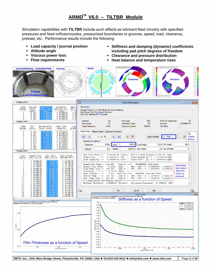
Simulation capabilities with TILTBR include such effects as lubricant feed circuitry with specified pressures and feed orifices/nozzles, pressurized boundaries or grooves, speed, load, clearance, preload, etc. Performance results include the following.
Journal Bearing – Unloaded Half Model
Load capacity / journal position Attitude angle Viscous power loss Flow requirements
Stiffness and damping (dynamic) coefficients including pad pitch degrees of freedom
Clearance and pressure distribution Heat balance and temperature rises
Drawing
5-PadsLoad Between Pads
Clearance Pressure
3D ViewerViewer Button
Generated t t t ttext output af ter Run button is pressed
Stiffness as a f nction of SpeedStiffness as a function of Speed.
Film-Thickness as a function of Speed.
RBTS, Inc., 1041 West Bridge Street, Phoenixville, PA 19460, USA Tel:610-415-0412 [email protected] www.rbts.com Page 3 of 20
The release of RBTS’ ARMD Version 6 TILTBR module is a major milestone in the
ARMD V6.0 – TILTBR ModuleTM
product’s development history, rolling out a completely new and improved graphical user interface for the package with enhanced numerical capabilities and new technical features. TILTBR software’s front end was redesigned with our customers’ and industry’s input to incorporate the most logical, efficient, and productive techniques to model and analyze common, as well as, complex bearing configurations with ease.
ARMD TILTBR ill i di t l th i t b i d i d tARMD TILTBR users will immediately see the improvements as bearing design data are presented in a flatter, more accessible format, with key fields and analysis options readily visible from the main data entry screens. Fluid-film bearing design and performance evaluation productivity is vastly improved as a wide selection of templates accompanied by a “wizard” style sequence of dialogs allows the user to setup and evaluate most of the commonly used bearings in industry with few key strokes. Tab selected grids and input forms allow the user to see all of the data on screen at the same time Furthermore theforms allow the user to see all of the data on screen at the same time. Furthermore, the ability to simultaneously run multiple instances of the program permits rapid side-by-side comparison of results.
A vastly improved pad configuration tab, on the basic bearing design input data form, allows the user to rapidly configure the pad and assembled bearing with complete freedom in pad and bearing attributes.in pad and bearing attributes.
By identifying new trends from industry, along with RBTS’ involvement in bearings design, performance evaluation and troubleshooting, new technical capabilities were added to the software including the ability to define pad pivot stiffness and pad leading/trailing edge tapers. User specified groove angle (angle between pads) allows the assembled bearing to have evenly spaced pads (typical industry design) or grouped pads.y p p ( yp y g ) g p p
Version 6 TILTBR users need only pick an overall grid density or design, and the user interface built-in analytical routines will generate the required grid network for the overall design, automatically modified as needed to add additional grid points at feature locations. Previous versions required the user to carefully design the fluid-film grid network in order to place design feature locations (like tapers, specified pressure regions, etc.) at existing grid points.
The grid design form now allows the user to specify grid locations by their physical positions instead of their incremental distance from their neighboring grid points. If a grid point increment is changed resulting in a mismatch between the size of the grid and the size of the bearing, a single button click will proportionately resize the grid to fit the bearing.
RBTS, Inc., 1041 West Bridge Street, Phoenixville, PA 19460, USA Tel:610-415-0412 [email protected] www.rbts.com Page 4 of 20
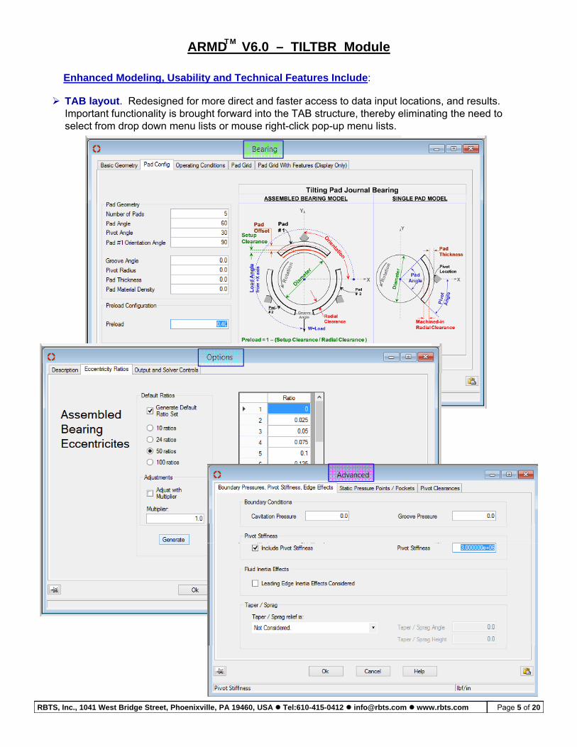
TAB layout. Redesigned for more direct and faster access to data input locations, and results. Important functionality is brought forward into the TAB structure, thereby eliminating the need to
Enhanced Modeling, Usability and Technical Features Include:
ARMD V6.0 – TILTBR ModuleTM
p y g y gselect from drop down menu lists or mouse right-click pop-up menu lists.
RBTS, Inc., 1041 West Bridge Street, Phoenixville, PA 19460, USA Tel:610-415-0412 [email protected] www.rbts.com Page 5 of 20
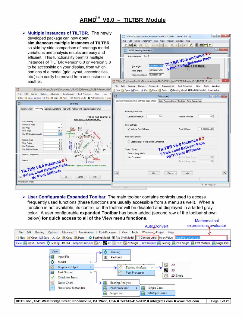
Multiple instances of TILTBR. The newly developed package can now open simultaneous multiple instances of TILTBR, so side-by-side comparison of bearings model
ARMD V6.0 – TILTBR ModuleTM
variations and analysis results are easy and efficient. This functionality permits multiple instances of TILTBR Version 6.0 or Version 5.8 to be accessible on your display, from which, portions of a model (grid layout, eccentricities, etc.) can easily be moved from one instance to another.
User Configurable Expanded Toolbar. The main toolbar contains controls used to access frequently used functions (these functions are usually accessible from a menu as well). When a function is not available, its control on the toolbar will be disabled and displayed in a faded gray color. A user configurable expanded Toolbar has been added (second row of the toolbar shown below) for quick access to all of the View menu functions.
Mathematical expressions evaluator Auto Convert
RBTS, Inc., 1041 West Bridge Street, Phoenixville, PA 19460, USA Tel:610-415-0412 [email protected] www.rbts.com Page 6 of 20
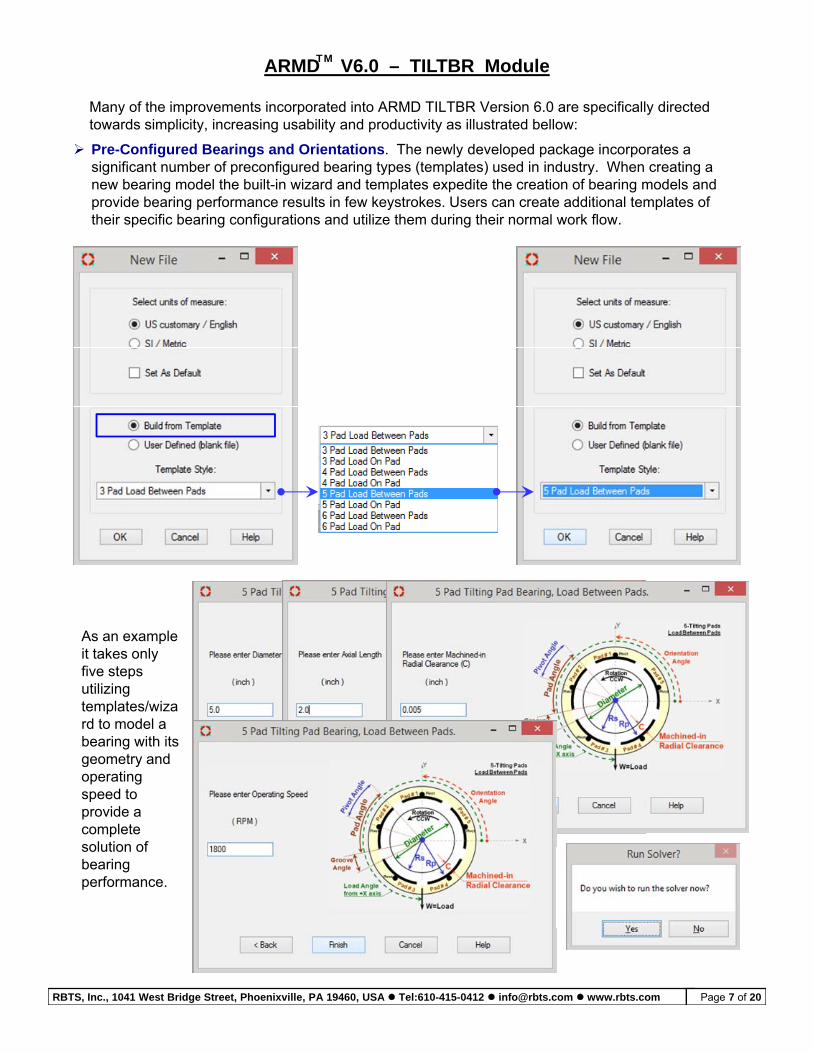
Many of the improvements incorporated into ARMD TILTBR Version 6.0 are specifically directed towards simplicity, increasing usability and productivity as illustrated bellow:
Pre-Configured Bearings and Orientations. The newly developed package incorporates a significant number of preconfigured bearing types (templates) used in industry When creating a
ARMD V6.0 – TILTBR ModuleTM
significant number of preconfigured bearing types (templates) used in industry. When creating a new bearing model the built-in wizard and templates expedite the creation of bearing models and provide bearing performance results in few keystrokes. Users can create additional templates of their specific bearing configurations and utilize them during their normal work flow.
As an example it takes only five steps utilizing templates/wizard to model a bearing with its geometry and g yoperating speed to provide a complete solution of bearing performance.performance.
RBTS, Inc., 1041 West Bridge Street, Phoenixville, PA 19460, USA Tel:610-415-0412 [email protected] www.rbts.com Page 7 of 20
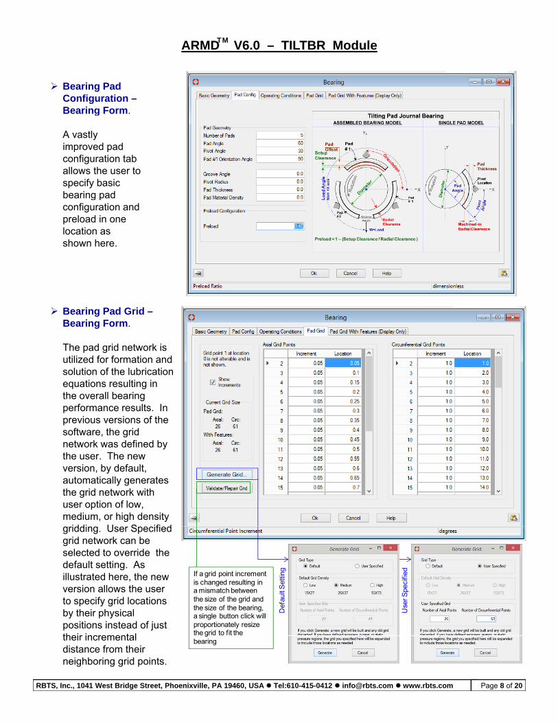
Bearing Pad Configuration –Bearing Form.
ARMD V6.0 – TILTBR ModuleTM
g
A vastly improved pad configuration tab allows the user to specify basic bearing padbearing pad configuration and preload in one location as shown here.
Bearing Pad Grid –Bearing Form.
The pad grid network is utilized for formation andutilized for formation and solution of the lubrication equations resulting in the overall bearing performance results. In previous versions of the software, the grid network was defined bynetwork was defined by the user. The new version, by default, automatically generates the grid network with user option of low, medium, or high density
iddi U S ifi dgridding. User Specified grid network can be selected to override the default setting. As illustrated here, the new version allows the user to specify grid locations
If a grid point increment is changed resulting in a mismatch between the size of the grid and the size of the bearing D
efau
lt S
ettin
g
Use
r Spe
cifie
d
by their physical positions instead of just their incremental distance from their neighboring grid points.
the size of the bearing, a single button click will proportionately resize the grid to fit the bearing
D U
RBTS, Inc., 1041 West Bridge Street, Phoenixville, PA 19460, USA Tel:610-415-0412 [email protected] www.rbts.com Page 8 of 20
ARMD V6.0 – TILTBR ModuleTM
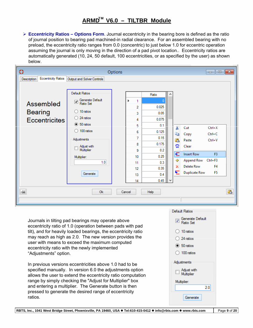
Eccentricity Ratios – Options Form. Journal eccentricity in the bearing bore is defined as the ratio of journal position to bearing pad machined-in radial clearance. For an assembled bearing with no preload, the eccentricity ratio ranges from 0.0 (concentric) to just below 1.0 for eccentric operation assuming the journal is only moving in the direction of a pad pivot location.. Eccentricity ratios are assu g e jou a s o y o g e d ec o o a pad p o oca o cce c y a os a eautomatically generated (10, 24, 50 default, 100 eccentricities, or as specified by the user) as shown below.
Journals in tilting pad bearings may operate above eccentricity ratio of 1.0 (operation between pads with pad tilt), and for heavily loaded bearings, the eccentricity ratio may reach as high as 2.0. The new version provides the ay eac as g as 0 e e e s o p o des euser with means to exceed the maximum computed eccentricity ratio with the newly implemented “Adjustments” option.
In previous versions eccentricities above 1.0 had to be specified manually. In version 6.0 the adjustments option allows the user to extend the eccentricity ratio computationallows the user to extend the eccentricity ratio computation range by simply checking the "Adjust for Multiplier" box and entering a multiplier. The Generate button is then pressed to generate the desired range of eccentricity ratios.
RBTS, Inc., 1041 West Bridge Street, Phoenixville, PA 19460, USA Tel:610-415-0412 [email protected] www.rbts.com Page 9 of 20
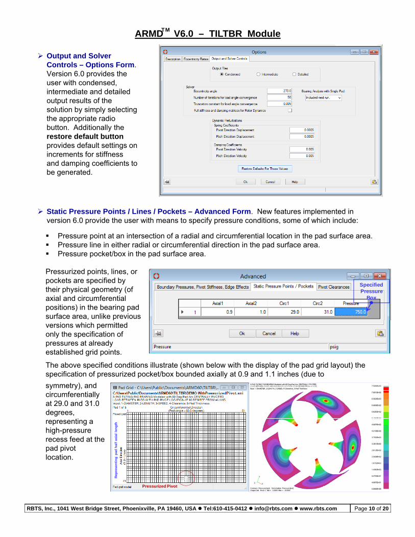
Output and Solver Controls – Options Form. Version 6.0 provides the user with condensed,
ARMD V6.0 – TILTBR ModuleTM
use co de sed,intermediate and detailed output results of the solution by simply selecting the appropriate radio button. Additionally the restore default buttonprovides default settings onprovides default settings on increments for stiffness and damping coefficients to be generated.
Static Pressure Points / Lines / Pockets – Advanced Form. New features implemented in version 6.0 provide the user with means to specify pressure conditions, some of which include:
Pressure point at an intersection of a radial and circumferential location in the pad surface area. Pressure line in either radial or circumferential direction in the pad surface area. Pressure pocket/box in the pad surface area.
Specified Pressure
Box
Pressurized points, lines, or pockets are specified by their physical geometry (of axial and circumferential positions) in the bearing pad surface area, unlike previous versions which permitted only the specification of pressures at already established grid points.
The above specified conditions illustrate (shown below with the display of the pad grid layout) the specification of pressurized pocket/box bounded axially at 0.9 and 1.1 inches (due to
symmetry), and
ad h
alf
axia
l le
ng
th
circumferentially at 29.0 and 31.0 degrees, representing a high-pressure recess feed at the pad pivot
Pressurized Pivot
Rep
rese
nti
ng
pa
p plocation.
RBTS, Inc., 1041 West Bridge Street, Phoenixville, PA 19460, USA Tel:610-415-0412 [email protected] www.rbts.com Page 10 of 20
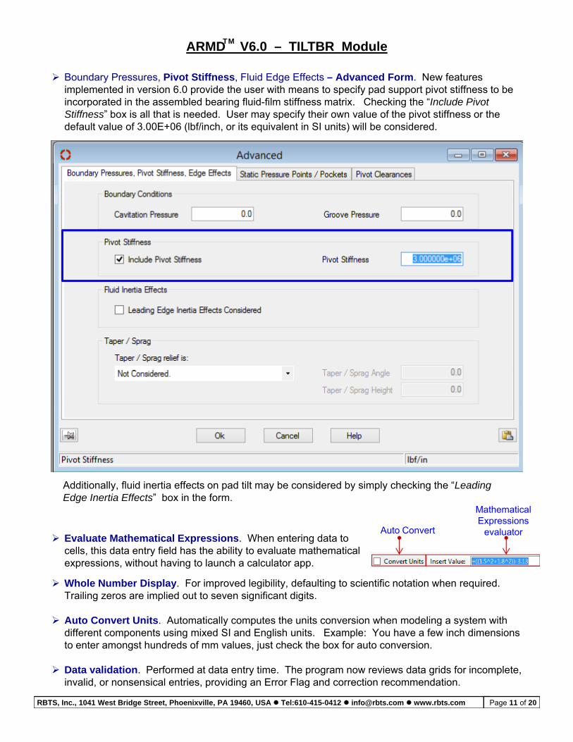
Boundary Pressures, Pivot Stiffness, Fluid Edge Effects – Advanced Form. New features implemented in version 6.0 provide the user with means to specify pad support pivot stiffness to be incorporated in the assembled bearing fluid-film stiffness matrix. Checking the “Include Pivot Stiffness” box is all that is needed. User may specify their own value of the pivot stiffness or the
ARMD V6.0 – TILTBR ModuleTM
S ess bo s a a s eeded Use ay spec y e o a ue o e p o s ess o edefault value of 3.00E+06 (lbf/inch, or its equivalent in SI units) will be considered.
Additionally, fluid inertia effects on pad tilt may be considered by simply checking the “Leading Edge Inertia Effects” box in the form.
Mathematical Expressions
evaluator Auto Convert Evaluate Mathematical Expressions When entering data to Evaluate Mathematical Expressions. When entering data to
cells, this data entry field has the ability to evaluate mathematical expressions, without having to launch a calculator app.
Whole Number Display. For improved legibility, defaulting to scientific notation when required. Trailing zeros are implied out to seven significant digits.
Auto Convert Units. Automatically computes the units conversion when modeling a system with uto Co e t U ts u o a ca y co pu es e u s co e s o e ode g a sys edifferent components using mixed SI and English units. Example: You have a few inch dimensions to enter amongst hundreds of mm values, just check the box for auto conversion.
Data validation. Performed at data entry time. The program now reviews data grids for incomplete, invalid, or nonsensical entries, providing an Error Flag and correction recommendation.
RBTS, Inc., 1041 West Bridge Street, Phoenixville, PA 19460, USA Tel:610-415-0412 [email protected] www.rbts.com Page 11 of 20
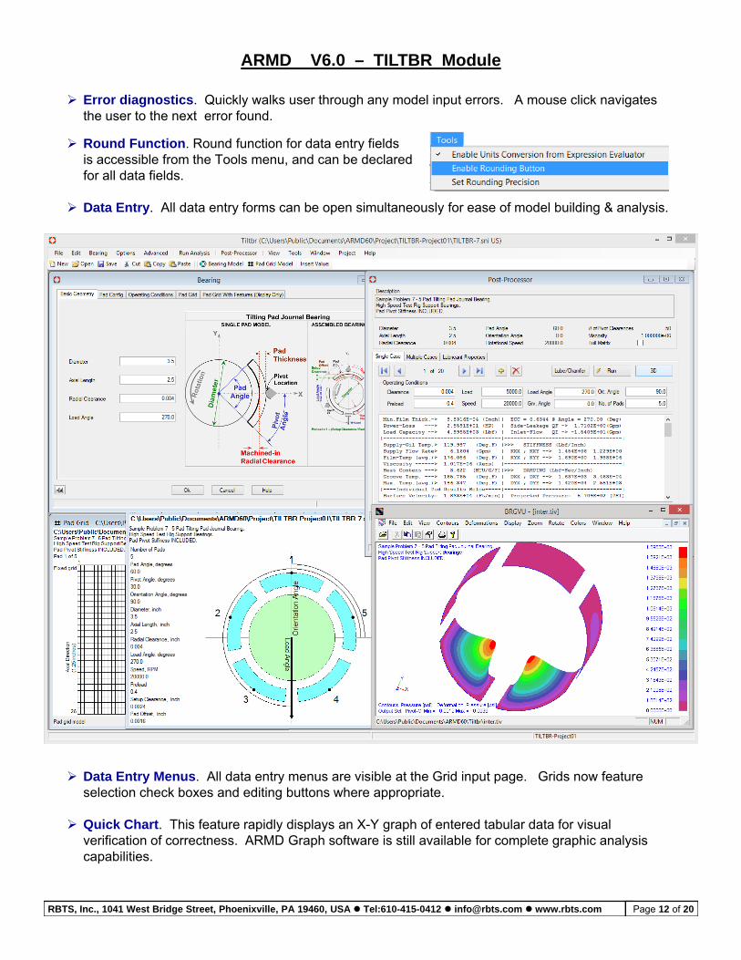
Round Function. Round function for data entry fields
ARMD V6.0 – TILTBR Module
Error diagnostics. Quickly walks user through any model input errors. A mouse click navigates the user to the next error found.
is accessible from the Tools menu, and can be declaredfor all data fields.
Data Entry. All data entry forms can be open simultaneously for ease of model building & analysis.
Data Entry Menus. All data entry menus are visible at the Grid input page. Grids now feature selection check boxes and editing buttons where appropriate.
Quick Chart. This feature rapidly displays an X-Y graph of entered tabular data for visual verification of correctness. ARMD Graph software is still available for complete graphic analysis capabilities.
RBTS, Inc., 1041 West Bridge Street, Phoenixville, PA 19460, USA Tel:610-415-0412 [email protected] www.rbts.com Page 12 of 20
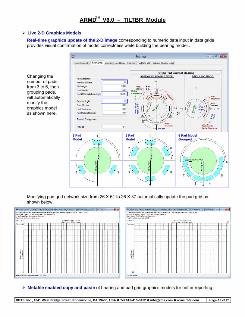
Live 2-D Graphics Models.
Real-time graphics update of the 2-D image corresponding to numeric data input in data grids provides visual confirmation of model correctness while building the bearing model..
ARMD V6.0 – TILTBR ModuleTM
Changing the number of pads from 3 to 6 thenfrom 3 to 6, then grouping pads, will automatically modify the graphics model as shown here.
3 PadModel
6 PadModel
6 Pad ModelGrouped
Modifying pad grid network size from 26 X 61 to 26 X 37 automatically update the pad grid as shown below.
Metafile enabled copy and paste of bearing and pad grid graphics models for better reporting.
RBTS, Inc., 1041 West Bridge Street, Phoenixville, PA 19460, USA Tel:610-415-0412 [email protected] www.rbts.com Page 13 of 20
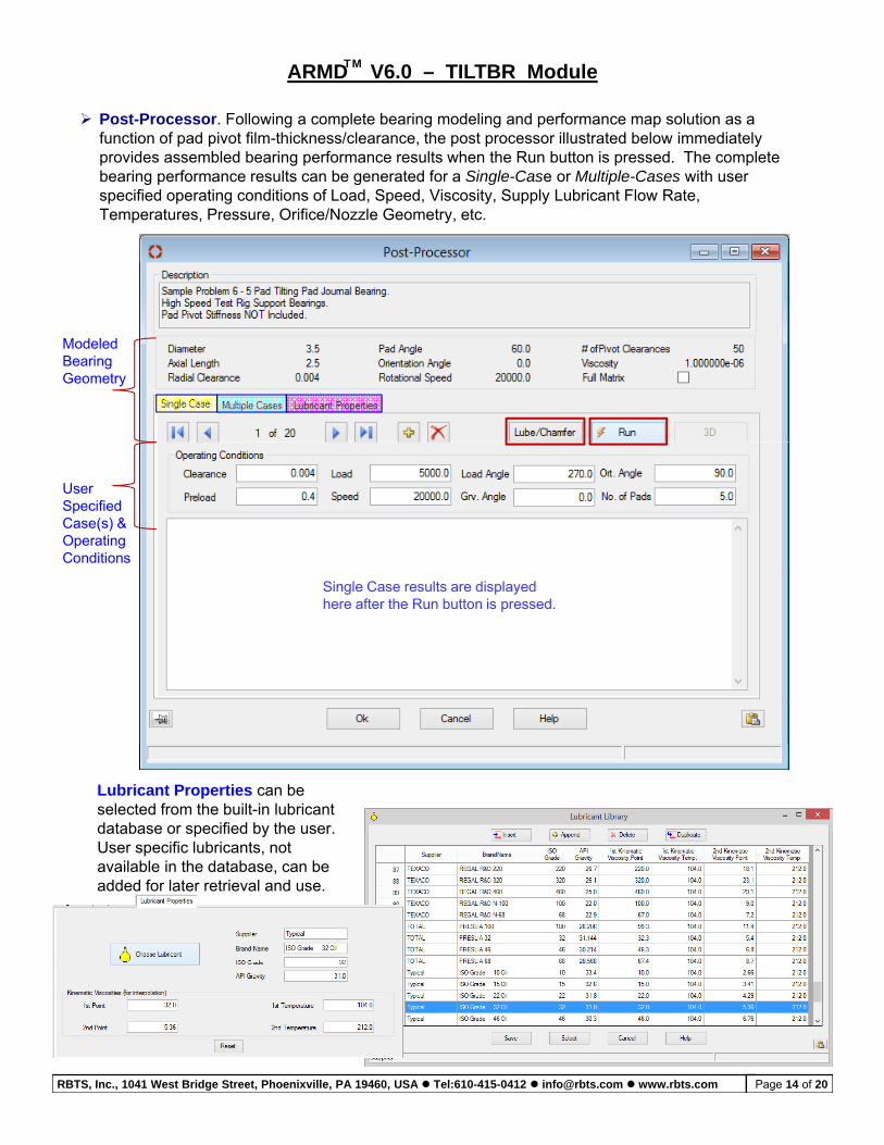
Post-Processor. Following a complete bearing modeling and performance map solution as a function of pad pivot film-thickness/clearance, the post processor illustrated below immediately provides assembled bearing performance results when the Run button is pressed. The complete bearing performance results can be generated for a Single-Case or Multiple-Cases with user
ARMD V6.0 – TILTBR ModuleTM
bea g pe o a ce esu s ca be ge e a ed o a S g e Case o u p e Cases usespecified operating conditions of Load, Speed, Viscosity, Supply Lubricant Flow Rate, Temperatures, Pressure, Orifice/Nozzle Geometry, etc.
Modeled Bearing Geometry
User Specified Case(s) & Operating Conditions
Single Case results are displayed here after the Run button is pressed.
Lubricant Properties can be selected from the built-in lubricant database or specified by the user.database or specified by the user. User specific lubricants, not available in the database, can be added for later retrieval and use.
RBTS, Inc., 1041 West Bridge Street, Phoenixville, PA 19460, USA Tel:610-415-0412 [email protected] www.rbts.com Page 14 of 20
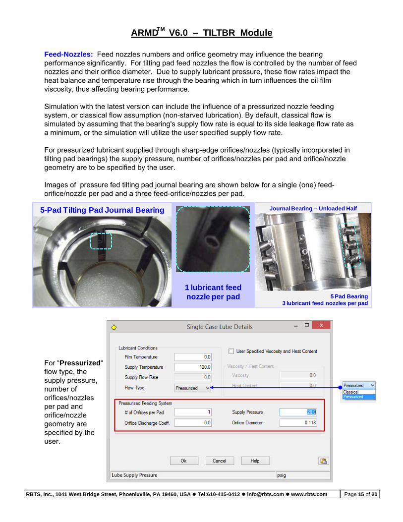
Feed-Nozzles: Feed nozzles numbers and orifice geometry may influence the bearing performance significantly. For tilting pad feed nozzles the flow is controlled by the number of feed nozzles and their orifice diameter. Due to supply lubricant pressure, these flow rates impact the heat balance and temperature rise through the bearing which in turn influences the oil film
ARMD V6.0 – TILTBR ModuleTM
ea ba a ce a d e pe a u e se oug e bea g c u ue ces e oviscosity, thus affecting bearing performance.
Simulation with the latest version can include the influence of a pressurized nozzle feeding system, or classical flow assumption (non-starved lubrication). By default, classical flow is simulated by assuming that the bearing's supply flow rate is equal to its side leakage flow rate as a minimum, or the simulation will utilize the user specified supply flow rate.
For pressurized lubricant supplied through sharp-edge orifices/nozzles (typically incorporated in tilting pad bearings) the supply pressure, number of orifices/nozzles per pad and orifice/nozzle geometry are to be specified by the user.
Images of pressure fed tilting pad journal bearing are shown below for a single (one) feed-orifice/nozzle per pad and a three feed-orifice/nozzles per pad.
5-Pad Tilting Pad Journal Bearing Journal Bearing – Unloaded Half
1 lubricant feed nozzle per pad 5 Pad Bearing
3 lubricant feed nozzles per pad
For “Pressurized“ flow type, the supply pressuresupply pressure, number of orifices/nozzles per pad and orifice/nozzle geometry are specified by the user.
RBTS, Inc., 1041 West Bridge Street, Phoenixville, PA 19460, USA Tel:610-415-0412 [email protected] www.rbts.com Page 15 of 20
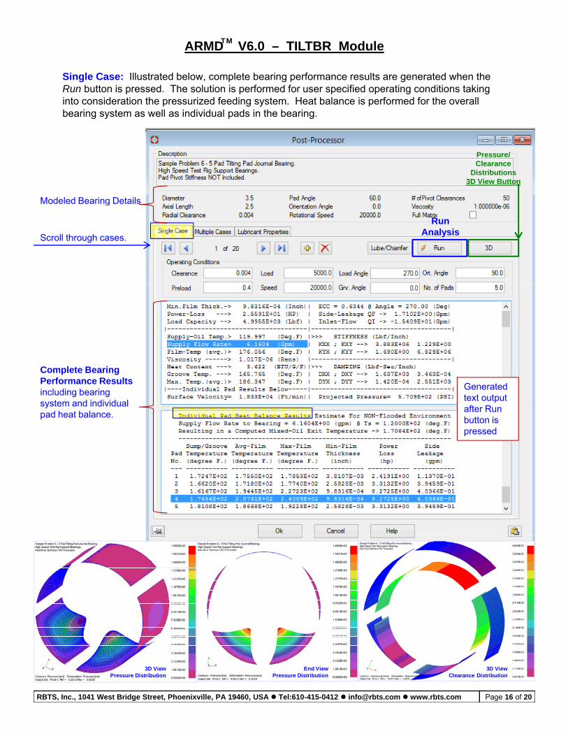
Single Case: Illustrated below, complete bearing performance results are generated when the Run button is pressed. The solution is performed for user specified operating conditions taking into consideration the pressurized feeding system. Heat balance is performed for the overall bearing system as well as individual pads in the bearing.
ARMD V6.0 – TILTBR ModuleTM
bea g sys e as e as d dua pads e bea g
Pressure/ Clearance
Distributions3D View Button
Modeled Bearing Details
RunAnalysis
Scroll through cases.
Modeled Bearing Details
C l t B iComplete Bearing Performance Results including bearing system and individual pad heat balance.
Generated text output after Run button is pressed
RBTS, Inc., 1041 West Bridge Street, Phoenixville, PA 19460, USA Tel:610-415-0412 [email protected] www.rbts.com Page 16 of 20
3D ViewPressure Distribution
End ViewPressure Distribution
3D ViewClearance Distribution
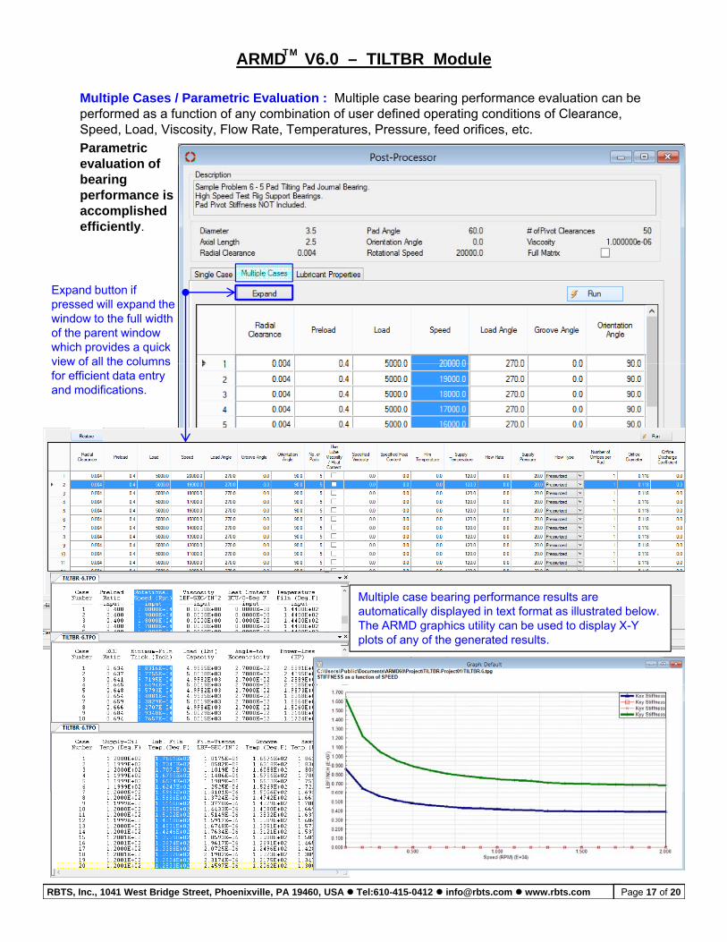
Multiple Cases / Parametric Evaluation : Multiple case bearing performance evaluation can be performed as a function of any combination of user defined operating conditions of Clearance, Speed, Load, Viscosity, Flow Rate, Temperatures, Pressure, feed orifices, etc.
Parametric
ARMD V6.0 – TILTBR ModuleTM
Parametric evaluation of bearing performance is accomplished efficiently.
Expand button if pressed will expand the window to the full width of the parent window which provides a quick view of all the columnsview of all the columns for efficient data entry and modifications.
Multiple case bearing performance results are automatically displayed in text format as illustrated below. The ARMD graphics utility can be used to display X-Y plots of any of the generated results.
RBTS, Inc., 1041 West Bridge Street, Phoenixville, PA 19460, USA Tel:610-415-0412 [email protected] www.rbts.com Page 17 of 20
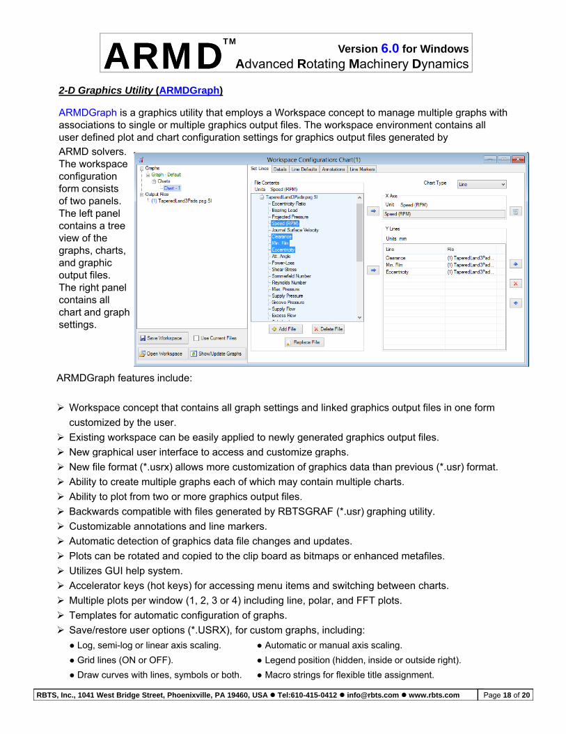
2-D Graphics Utility (ARMDGraph)
ARMDGraph is a graphics utility that employs a Workspace concept to manage multiple graphs with
Version 6.0 for Windows
Advanced Rotating Machinery DynamicsARMDARMDTM
ARMD solvers.The workspace configuration form consistsof two panels
p g p y p y p p g p g passociations to single or multiple graphics output files. The workspace environment contains all user defined plot and chart configuration settings for graphics output files generated by
of two panels. The left panel contains a tree view of the graphs, charts, and graphic output files. The right panel contains all chart and graph settings.
ARMDGraph features include:
Workspace concept that contains all graph settings and linked graphics output files in one form
customized by the user.
Existing workspace can be easily applied to newly generated graphics output files.
New graphical user interface to access and customize graphs New graphical user interface to access and customize graphs.
New file format (*.usrx) allows more customization of graphics data than previous (*.usr) format.
Ability to create multiple graphs each of which may contain multiple charts.
Ability to plot from two or more graphics output files.
Backwards compatible with files generated by RBTSGRAF (*.usr) graphing utility.
Customizable annotations and line markers.
Automatic detection of graphics data file changes and updates.
Plots can be rotated and copied to the clip board as bitmaps or enhanced metafiles.
Utilizes GUI help system.
Accelerator keys (hot keys) for accessing menu items and switching between charts.
Multiple plots per window (1, 2, 3 or 4) including line, polar, and FFT plots.
Templates for automatic configuration of graphs Templates for automatic configuration of graphs.
Save/restore user options (*.USRX), for custom graphs, including:
● Log, semi-log or linear axis scaling. ● Automatic or manual axis scaling.
● Grid lines (ON or OFF). ● Legend position (hidden, inside or outside right).
● Draw curves with lines, symbols or both. ● Macro strings for flexible title assignment.
RBTS, Inc., 1041 West Bridge Street, Phoenixville, PA 19460, USA Tel:610-415-0412 [email protected] www.rbts.com Page 18 of 20
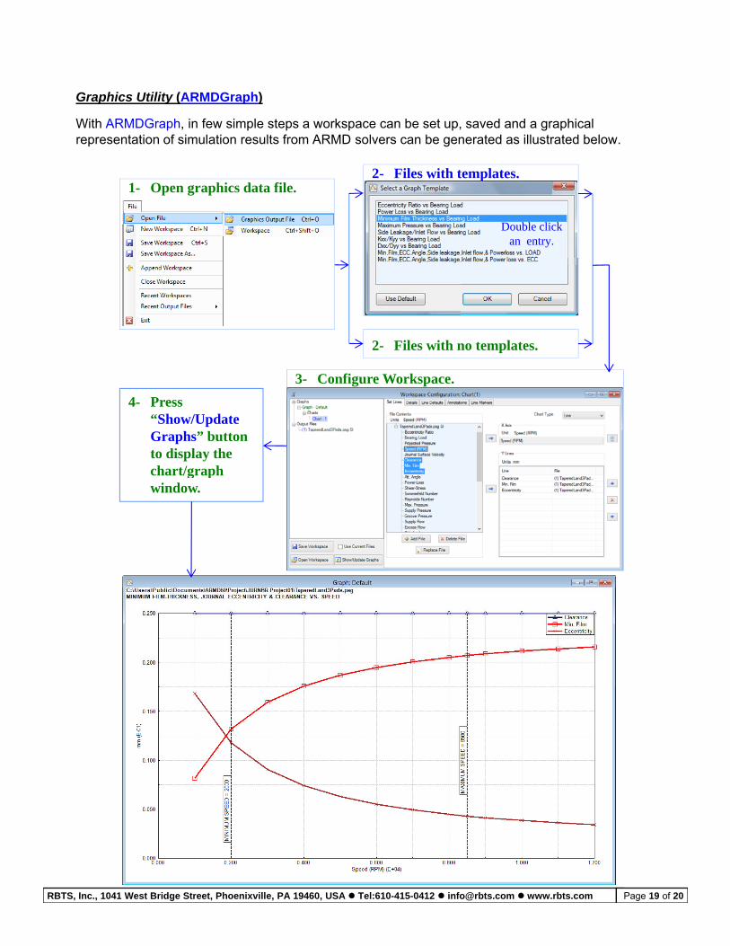
Graphics Utility (ARMDGraph)
With ARMDGraph, in few simple steps a workspace can be set up, saved and a graphical representation of simulation results from ARMD solvers can be generated as illustrated below.
1- Open graphics data file.2- Files with templates.
Double click an entry.
2- Files with no templates.
3- Configure Workspace.
4- Press “Show/Update Graphs” button to display the chart/graphchart/graph window.
RBTS, Inc., 1041 West Bridge Street, Phoenixville, PA 19460, USA Tel:610-415-0412 [email protected] www.rbts.com Page 19 of 20
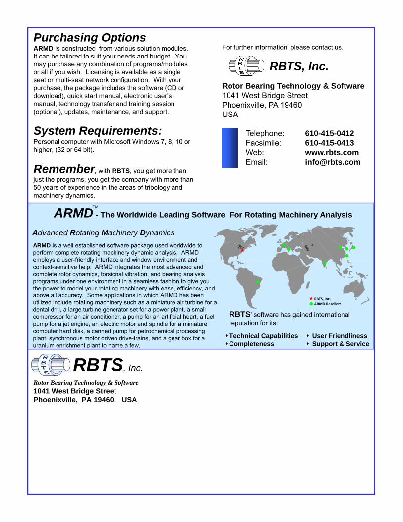
Purchasing OptionsARMD is constructed from various solution modules. It can be tailored to suit your needs and budget. You may purchase any combination of programs/modules or all if you wish. Licensing is available as a single seat or multi-seat network configuration. With your
For further information, please contact us.
RBTS, Inc.
& S fg y
purchase, the package includes the software (CD or download), quick start manual, electronic user’s manual, technology transfer and training session (optional), updates, maintenance, and support.
System Requirements:Personal computer with Microsoft Windows 7 8 10 or
Rotor Bearing Technology & Software1041 West Bridge StreetPhoenixville, PA 19460USA
Telephone: 610-415-0412Facsimile: 610 415 0413Personal computer with Microsoft Windows 7, 8, 10 or
higher, (32 or 64 bit).
Remember, with RBTS, you get more than just the programs, you get the company with more than 50 years of experience in the areas of tribology and machinery dynamics.
Facsimile: 610-415-0413Web: www.rbts.comEmail: [email protected]
Advanced Rotating Machinery Dynamics
ARMD is a well established software package used worldwide to perform complete rotating machinery dynamic analysis. ARMD employs a user-friendly interface and window environment and
TM
ARMD - The Worldwide Leading Software For Rotating Machinery Analysis
RBTS, Inc.ARMD Resellers
employs a user friendly interface and window environment and context-sensitive help. ARMD integrates the most advanced and complete rotor dynamics, torsional vibration, and bearing analysis programs under one environment in a seamless fashion to give you the power to model your rotating machinery with ease, efficiency, and above all accuracy. Some applications in which ARMD has been utilized include rotating machinery such as a miniature air turbine for a dental drill, a large turbine generator set for a power plant, a small compressor for an air conditioner, a pump for an artificial heart, a fuel RBTS' software has gained internationalpump for a jet engine, an electric motor and spindle for a miniature computer hard disk, a canned pump for petrochemical processing plant, synchronous motor driven drive-trains, and a gear box for a uranium enrichment plant to name a few.
RBTS, Inc.
reputation for its:
Technical Capabilities User FriendlinessCompleteness Support & Service
Rotor Bearing Technology & Software1041 West Bridge StreetPhoenixville, PA 19460, USA