special types of bearings i) aerodynamic bearings - … bearings cannot pass bending ... aerodynamic...
TRANSCRIPT

Special types of bearings 1
Special types of bearings I) Aerodynamic bearings
Aerodynamic bearings operate on similar principle as hydrodynamic bearings, the only difference being that the process medium is gas instead of fluid. The pressure in bearing gap, which supports the bearing load, is generated solely by mutual movement of sliding surfaces, as differs from aerostatic bearings, which need supply of compressed gas from external source. The difference between dynamic viscosity of common oils and that of most gases is about 3 orders; thus we had to reckon with adequately lower load capacity and stiffness of aerodynamic bearings as compared with hydrodynamic ones. This handicap can be compensated by increasing the bearing dimensions, while preserving favourable friction losses given also by much lower viscosity of gases. Greater bearing diameter has positive effect also on rotor rigidity and through it on its bending critical speed. It makes the machine design easier, because rotors in aerodynamic bearings cannot pass bending critical speed due to low damping. Individual types of aerodynamic bearings, their properties and possibility of application are briefly described bellow.
A) Journal bearings
1) Circular bearing: not suitable for practical use because of very low stability limit
2) Spiral groove bearing: used in practise, but its production technology is relatively demanding; applicable only with very small bearing clearance, which increases requirements on accuracy of manufacture and adjustment
Special types of bearings 2
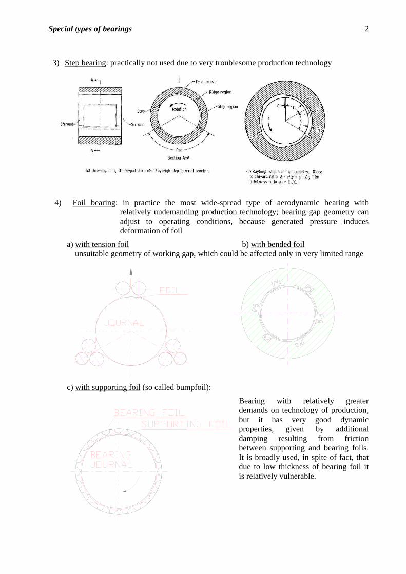
3) Step bearing: practically not used due to very troublesome production technology
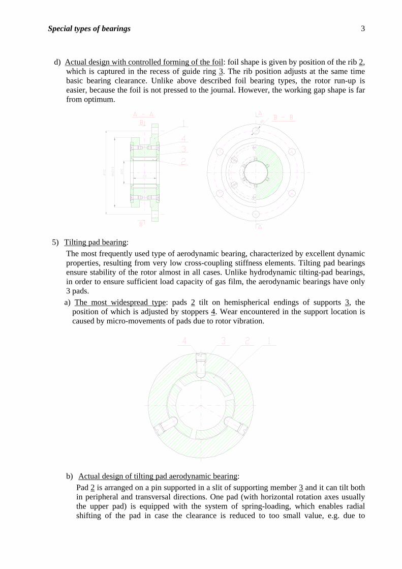
4) Foil bearing: in practice the most wide-spread type of aerodynamic bearing with relatively undemanding production technology; bearing gap geometry can adjust to operating conditions, because generated pressure induces deformation of foil
a) with tension foil b) with bended foil unsuitable geometry of working gap, which could be affected only in very limited range
c) with supporting foil (so called bumpfoil):
Bearing with relatively greater demands on technology of production, but it has very good dynamic properties, given by additional damping resulting from friction between supporting and bearing foils. It is broadly used, in spite of fact, that due to low thickness of bearing foil it is relatively vulnerable.
Special types of bearings 3
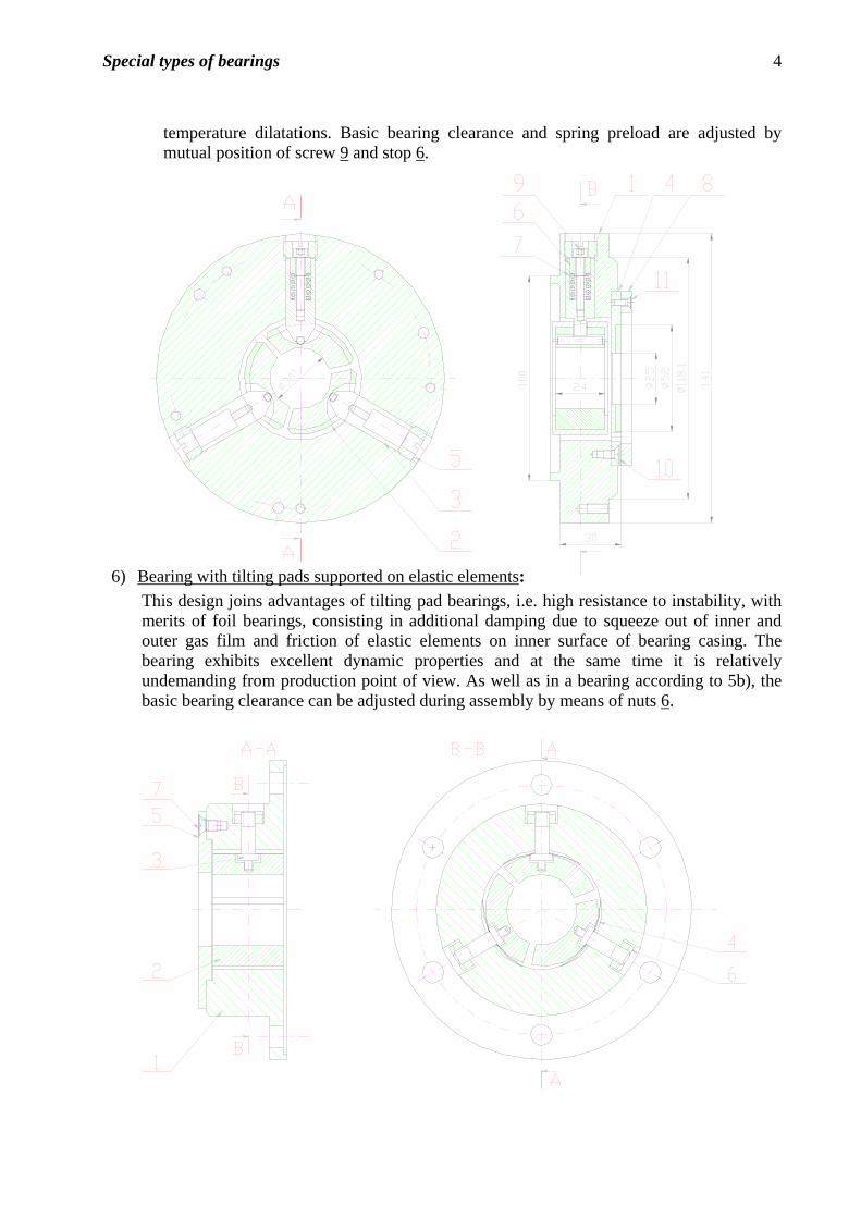
d) Actual design with controlled forming of the foil : foil shape is given by position of the rib 2, which is captured in the recess of guide ring 3. The rib position adjusts at the same time basic bearing clearance. Unlike above described foil bearing types, the rotor run-up is easier, because the foil is not pressed to the journal. However, the working gap shape is far from optimum.
5) Tilting pad bearing:
The most frequently used type of aerodynamic bearing, characterized by excellent dynamic properties, resulting from very low cross-coupling stiffness elements. Tilting pad bearings ensure stability of the rotor almost in all cases. Unlike hydrodynamic tilting-pad bearings, in order to ensure sufficient load capacity of gas film, the aerodynamic bearings have only 3 pads.
a) The most widespread type: pads 2 tilt on hemispherical endings of supports 3, the position of which is adjusted by stoppers 4. Wear encountered in the support location is caused by micro-movements of pads due to rotor vibration.
b) Actual design of tilting pad aerodynamic bearing:
Pad 2 is arranged on a pin supported in a slit of supporting member 3 and it can tilt both in peripheral and transversal directions. One pad (with horizontal rotation axes usually the upper pad) is equipped with the system of spring-loading, which enables radial shifting of the pad in case the clearance is reduced to too small value, e.g. due to
Special types of bearings 4
temperature dilatations. Basic bearing clearance and spring preload are adjusted by mutual position of screw 9 and stop 6.
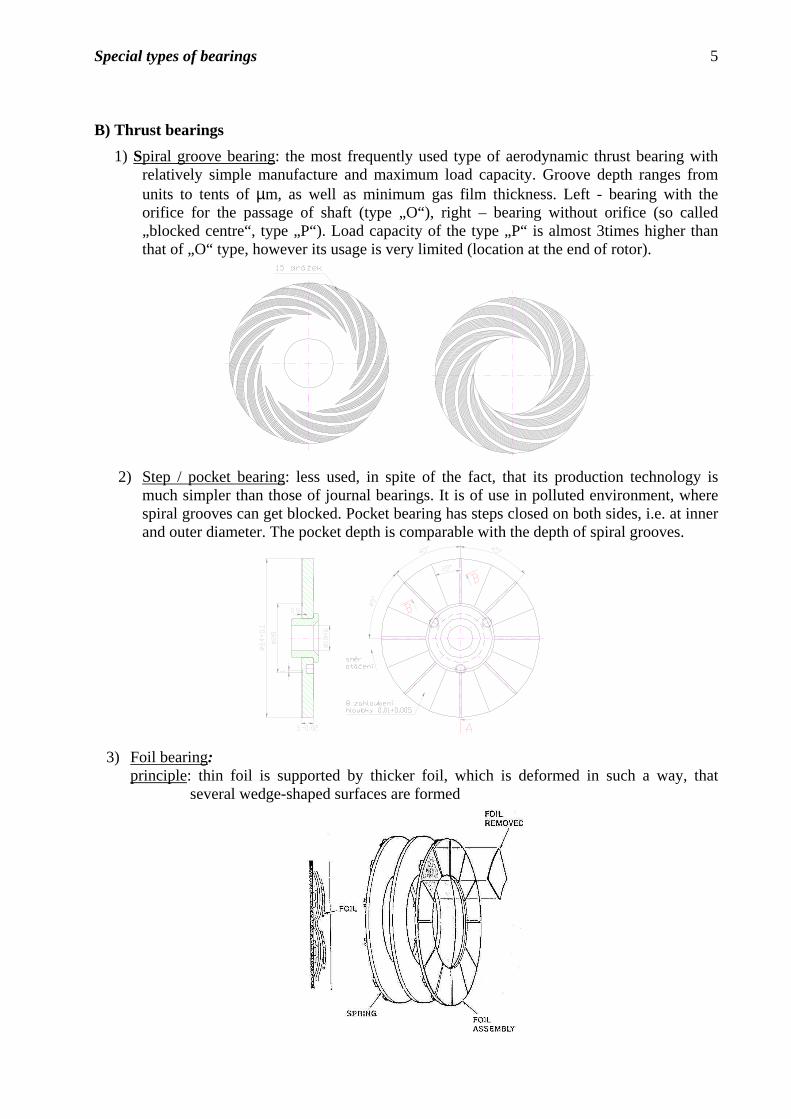
6) Bearing with tilting pads supported on elastic elements: This design joins advantages of tilting pad bearings, i.e. high resistance to instability, with merits of foil bearings, consisting in additional damping due to squeeze out of inner and outer gas film and friction of elastic elements on inner surface of bearing casing. The bearing exhibits excellent dynamic properties and at the same time it is relatively undemanding from production point of view. As well as in a bearing according to 5b), the basic bearing clearance can be adjusted during assembly by means of nuts 6.
Special types of bearings 5
B) Thrust bearings
1) Spiral groove bearing: the most frequently used type of aerodynamic thrust bearing with relatively simple manufacture and maximum load capacity. Groove depth ranges from units to tents of µm, as well as minimum gas film thickness. Left - bearing with the orifice for the passage of shaft (type „O“), right – bearing without orifice (so called „blocked centre“, type „P“). Load capacity of the type „P“ is almost 3times higher than that of „O“ type, however its usage is very limited (location at the end of rotor).
2) Step / pocket bearing: less used, in spite of the fact, that its production technology is
much simpler than those of journal bearings. It is of use in polluted environment, where spiral grooves can get blocked. Pocket bearing has steps closed on both sides, i.e. at inner and outer diameter. The pocket depth is comparable with the depth of spiral grooves.
3) Foil bearing: principle: thin foil is supported by thicker foil, which is deformed in such a way, that
several wedge-shaped surfaces are formed
Special types of bearings 6
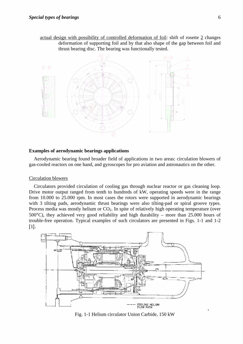
actual design with possibility of controlled deformation of foil: shift of rosette 2 changes deformation of supporting foil and by that also shape of the gap between foil and thrust bearing disc. The bearing was functionally tested.
82
72
Examples of aerodynamic bearings applications
Aerodynamic bearing found broader field of applications in two areas: circulation blowers of gas-cooled reactors on one hand, and gyroscopes for pro aviation and astronautics on the other.
Circulation blowers
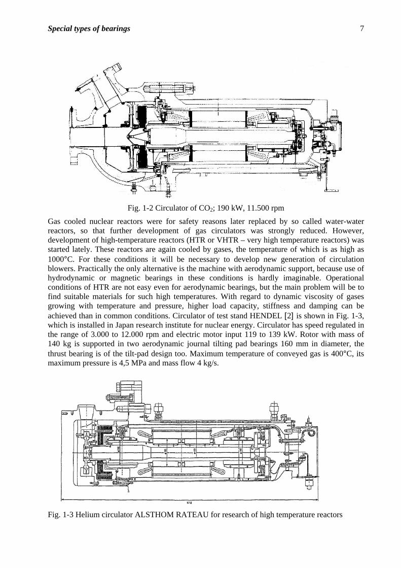
Circulators provided circulation of cooling gas through nuclear reactor or gas cleaning loop. Drive motor output ranged from tenth to hundreds of kW, operating speeds were in the range from 10.000 to 25.000 rpm. In most cases the rotors were supported in aerodynamic bearings with 3 tilting pads, aerodynamic thrust bearings were also tilting-pad or spiral groove types. Process media was mostly helium or CO2. In spite of relatively high operating temperature (over 500°C), they achieved very good reliability and high durability – more than 25.000 hours of trouble-free operation. Typical examples of such circulators are presented in Figs. 1-1 and 1-2 [1].
. Fig. 1-1 Helium circulator Union Carbide, 150 kW
Special types of bearings 7
Fig. 1-2 Circulator of CO2; 190 kW, 11.500 rpm
Gas cooled nuclear reactors were for safety reasons later replaced by so called water-water reactors, so that further development of gas circulators was strongly reduced. However, development of high-temperature reactors (HTR or VHTR – very high temperature reactors) was started lately. These reactors are again cooled by gases, the temperature of which is as high as 1000°C. For these conditions it will be necessary to develop new generation of circulation blowers. Practically the only alternative is the machine with aerodynamic support, because use of hydrodynamic or magnetic bearings in these conditions is hardly imaginable. Operational conditions of HTR are not easy even for aerodynamic bearings, but the main problem will be to find suitable materials for such high temperatures. With regard to dynamic viscosity of gases growing with temperature and pressure, higher load capacity, stiffness and damping can be achieved than in common conditions. Circulator of test stand HENDEL [2] is shown in Fig. 1-3, which is installed in Japan research institute for nuclear energy. Circulator has speed regulated in the range of 3.000 to 12.000 rpm and electric motor input 119 to 139 kW. Rotor with mass of 140 kg is supported in two aerodynamic journal tilting pad bearings 160 mm in diameter, the thrust bearing is of the tilt-pad design too. Maximum temperature of conveyed gas is 400°C, its maximum pressure is 4,5 MPa and mass flow 4 kg/s.
Fig. 1-3 Helium circulator ALSTHOM RATEAU for research of high temperature reactors
Special types of bearings 8
Gyroscopes
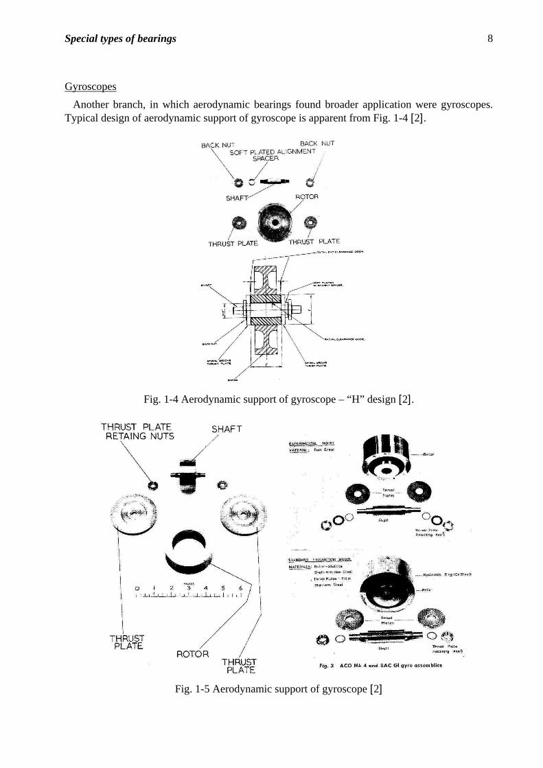
Another branch, in which aerodynamic bearings found broader application were gyroscopes. Typical design of aerodynamic support of gyroscope is apparent from Fig. 1-4 [2].
Fig. 1-4 Aerodynamic support of gyroscope – “H” design [2].
Fig. 1-5 Aerodynamic support of gyroscope [2]
Special types of bearings 9
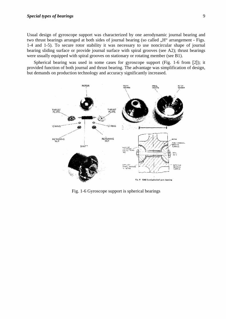
Usual design of gyroscope support was characterized by one aerodynamic journal bearing and two thrust bearings arranged at both sides of journal bearing (so called „H“ arrangement - Figs. 1-4 and 1-5). To secure rotor stability it was necessary to use noncircular shape of journal bearing sliding surface or provide journal surface with spiral grooves (see A2); thrust bearings were usually equipped with spiral grooves on stationary or rotating member (see B1).
Spherical bearing was used in some cases for gyroscope support (Fig. 1-6 from [2]); it provided function of both journal and thrust bearing. The advantage was simplification of design, but demands on production technology and accuracy significantly increased.
Fig. 1-6 Gyroscope support is spherical bearings
Special types of bearings 10
Applications of aerodynamic bearings realized in Czech Republic
1. Expansion turbines for helium liquefaction:
One of the first and at the same time most successful applications of aerodynamic bearings was rotor support of helium liquefaction expansion turbine (Fig. 1-7).
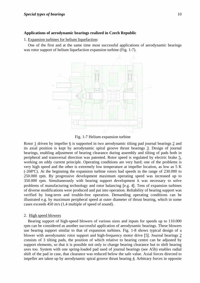
Fig. 1-7 Helium expansion turbine
Rotor 1 driven by impeller 6 is supported in two aerodynamic tilting pad journal bearings 2 and its axial position is kept by aerodynamic spiral groove thrust bearings 3. Design of journal bearings, enabling adjustment of bearing clearance during assembly and tilting of pads both in peripheral and transversal direction was patented. Rotor speed is regulated by electric brake 5, working on eddy current principle. Operating conditions are very hard; one of the problems is very high speed and the other is extremely low temperature at impeller location, as low as 5 K (-268ºC). At the beginning the expansion turbine rotors had speeds in the range of 230.000 to 250.000 rpm. By progressive development maximum operating speed was increased up to 350.000 rpm. Simultaneously with bearing support development it was necessary to solve problems of manufacturing technology and rotor balancing [e.g. 4]. Tens of expansion turbines of diverse modifications were produced and put into operation. Reliability of bearing support was verified by long-term and trouble-free operation. Demanding operating conditions can be illustrated e.g. by maximum peripheral speed at outer diameter of thrust bearing, which in some cases exceeds 450 m/s (1,4 multiple of speed of sound).
2. High speed blowers
Bearing support of high-speed blowers of various sizes and inputs for speeds up to 110.000 rpm can be considered as another successful application of aerodynamic bearings. These blowers use bearing support similar to that of expansion turbines. Fig. 1-8 shows typical design of a blower with aerodynamic rotor support and high-frequency motor drive [5]. Journal bearings 2 consists of 3 tilting pads, the position of which relative to bearing centre can be adjusted by support elements, so that it is possible not only to change bearing clearance but to shift bearing axes too. System with one spring-loaded pad used of journal bearings (see A5b) enables radial shift of the pad in case, that clearance was reduced below the safe value. Axial forces directed to impeller are taken up by aerodynamic spiral groove thrust bearing 4. Arbitrary forces in opposite
Special types of bearings 11
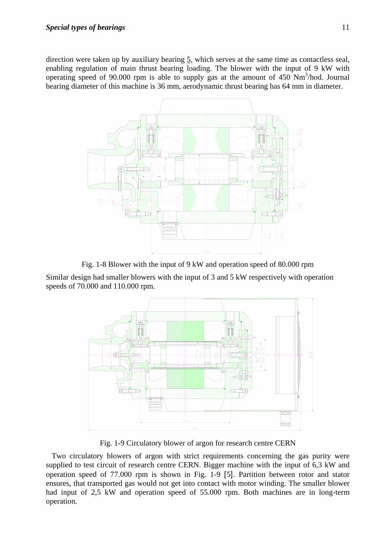
direction were taken up by auxiliary bearing 5, which serves at the same time as contactless seal, enabling regulation of main thrust bearing loading. The blower with the input of 9 kW with operating speed of 90.000 rpm is able to supply gas at the amount of 450 Nm3/hod. Journal bearing diameter of this machine is 36 mm, aerodynamic thrust bearing has 64 mm in diameter.
Fig. 1-8 Blower with the input of 9 kW and operation speed of 80.000 rpm
Similar design had smaller blowers with the input of 3 and 5 kW respectively with operation speeds of 70.000 and 110.000 rpm.
(52)
(38)
Fig. 1-9 Circulatory blower of argon for research centre CERN
Two circulatory blowers of argon with strict requirements concerning the gas purity were supplied to test circuit of research centre CERN. Bigger machine with the input of 6,3 kW and operation speed of 77.000 rpm is shown in Fig. 1-9 [5]. Partition between rotor and stator ensures, that transported gas would not get into contact with motor winding. The smaller blower had input of 2,5 kW and operation speed of 55.000 rpm. Both machines are in long-term operation.
Special types of bearings 12
Aerodynamic bearing support of the blower with the input of 100 kW and operation speed of 18.000 rpm was designed and tested in scope of grant project of Academy of Sciences of Czech Republic (Fig. 1-10).
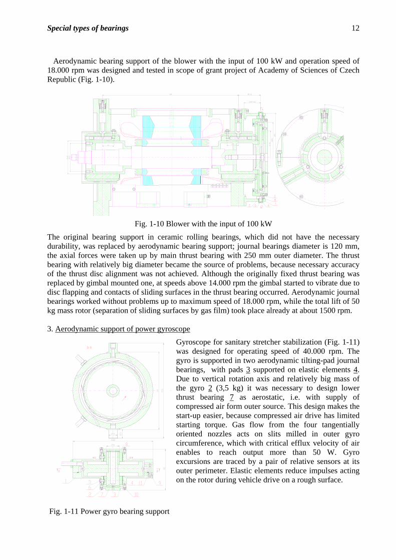
Fig. 1-10 Blower with the input of 100 kW
The original bearing support in ceramic rolling bearings, which did not have the necessary durability, was replaced by aerodynamic bearing support; journal bearings diameter is 120 mm, the axial forces were taken up by main thrust bearing with 250 mm outer diameter. The thrust bearing with relatively big diameter became the source of problems, because necessary accuracy of the thrust disc alignment was not achieved. Although the originally fixed thrust bearing was replaced by gimbal mounted one, at speeds above 14.000 rpm the gimbal started to vibrate due to disc flapping and contacts of sliding surfaces in the thrust bearing occurred. Aerodynamic journal bearings worked without problems up to maximum speed of 18.000 rpm, while the total lift of 50 kg mass rotor (separation of sliding surfaces by gas film) took place already at about 1500 rpm. 3. Aerodynamic support of power gyroscope
Gyroscope for sanitary stretcher stabilization (Fig. 1-11) was designed for operating speed of 40.000 rpm. The gyro is supported in two aerodynamic tilting-pad journal bearings, with pads 3 supported on elastic elements 4. Due to vertical rotation axis and relatively big mass of the gyro 2 (3,5 kg) it was necessary to design lower thrust bearing 7 as aerostatic, i.e. with supply of compressed air form outer source. This design makes the start-up easier, because compressed air drive has limited starting torque. Gas flow from the four tangentially oriented nozzles acts on slits milled in outer gyro circumference, which with critical efflux velocity of air enables to reach output more than 50 W. Gyro excursions are traced by a pair of relative sensors at its outer perimeter. Elastic elements reduce impulses acting on the rotor during vehicle drive on a rough surface.
Fig. 1-11 Power gyro bearing support

Special types of bearings 13
II) Aerostatic bearings
Aerostatic bearings need for their operation external source of compressed gas. Due to supply of pressurized gas they work even without any relative movement of sliding surfaces. Gas film of relatively high stiffness quite separates sliding surfaces and compensates their unevenness and roughness so that excellent precision of running can be achieved. Advantageous is also very low friction, disregarding speed of sliding surfaces relative movement, and from it resulting low heat generation.
A) Journal bearings
1) Bearing with s discrete feeding orifices: the most frequent type of aerostatic bearings; compressed gas is fed to the bearing by orifices, arranged in one or two planes around bearing periphery
2) Porous bearing: compressed gas is fed to working gap through the pores of bearing lining (e.g. un-impregnated electrographite, sintered bronze), thus across the whole sliding surface. Gas utilization is more effective and its consumption is therefore lower. The load capacity is greater due to supply of gas over the whole sliding surface. It is possible to combine porous material with discrete orifices and thus achieve optimum bearing properties.
radi-axial bearing journal bearing
+0,01
+0,01
Special types of bearings 14
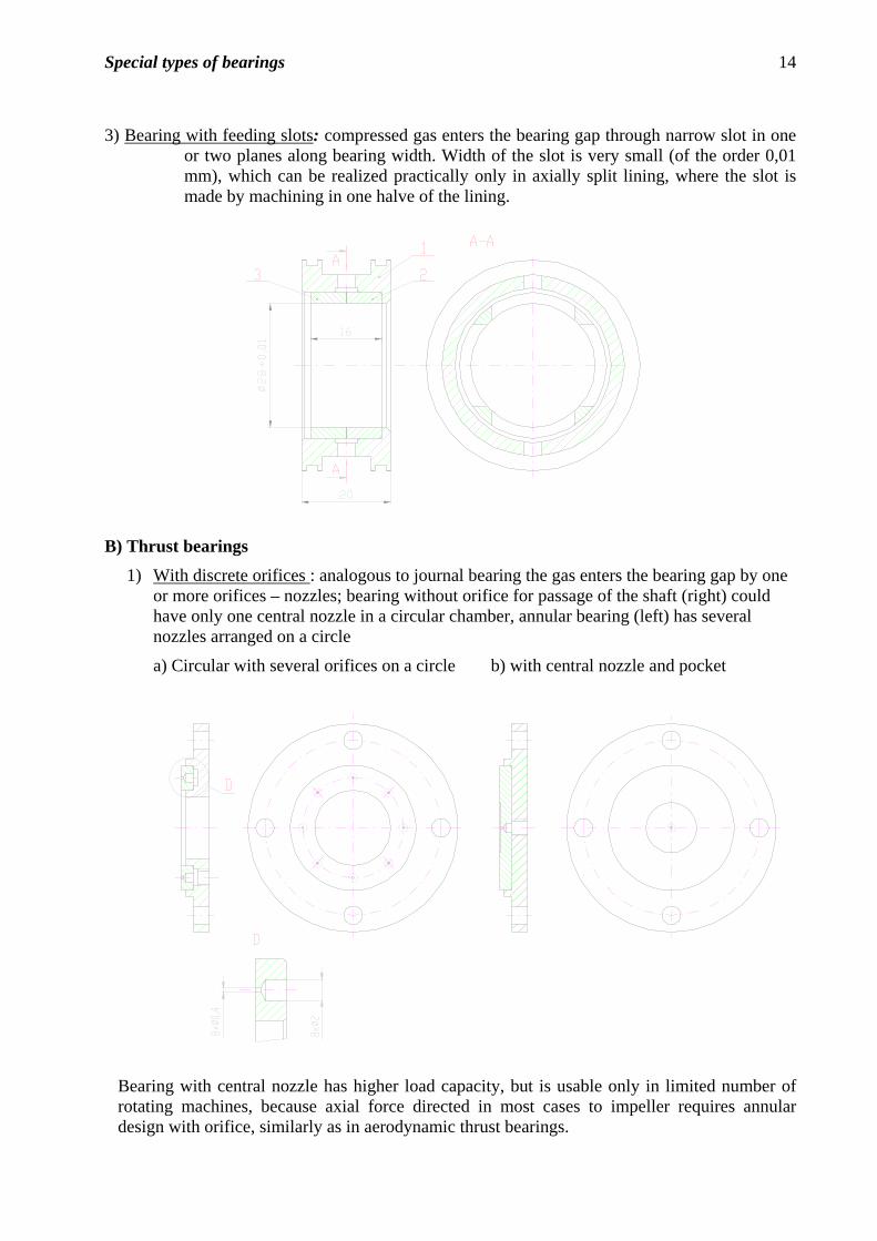
3) Bearing with feeding slots: compressed gas enters the bearing gap through narrow slot in one or two planes along bearing width. Width of the slot is very small (of the order 0,01 mm), which can be realized practically only in axially split lining, where the slot is made by machining in one halve of the lining.
+0,01
B) Thrust bearings
1) With discrete orifices : analogous to journal bearing the gas enters the bearing gap by one or more orifices – nozzles; bearing without orifice for passage of the shaft (right) could have only one central nozzle in a circular chamber, annular bearing (left) has several nozzles arranged on a circle
a) Circular with several orifices on a circle b) with central nozzle and pocket
Bearing with central nozzle has higher load capacity, but is usable only in limited number of rotating machines, because axial force directed in most cases to impeller requires annular design with orifice, similarly as in aerodynamic thrust bearings.
Special types of bearings 15
Examples of aerostatic bearings applications
The greatest advantages of aerostatic bearings consist in relatively high stiffness, high precision of operation and the fact, that even at run-up and run-down there is no contact between sliding surfaces and thus no wear. These properties determine two biggest areas of application, i.e. machine tools and measuring devices. From measuring devices one can name three-coordinate measuring machines, at which plane aerostatic bearings are used for linear feeding as well as journal bearings for rotational movement in spindles.
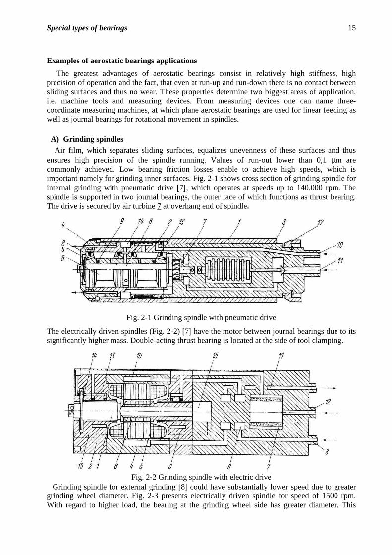
A) Grinding spindles Air film, which separates sliding surfaces, equalizes unevenness of these surfaces and thus ensures high precision of the spindle running. Values of run-out lower than 0,1 µm are commonly achieved. Low bearing friction losses enable to achieve high speeds, which is important namely for grinding inner surfaces. Fig. 2-1 shows cross section of grinding spindle for internal grinding with pneumatic drive [7], which operates at speeds up to 140.000 rpm. The spindle is supported in two journal bearings, the outer face of which functions as thrust bearing. The drive is secured by air turbine 7 at overhang end of spindle.
Fig. 2-1 Grinding spindle with pneumatic drive
The electrically driven spindles (Fig. 2-2) [7] have the motor between journal bearings due to its significantly higher mass. Double-acting thrust bearing is located at the side of tool clamping.
Fig. 2-2 Grinding spindle with electric drive
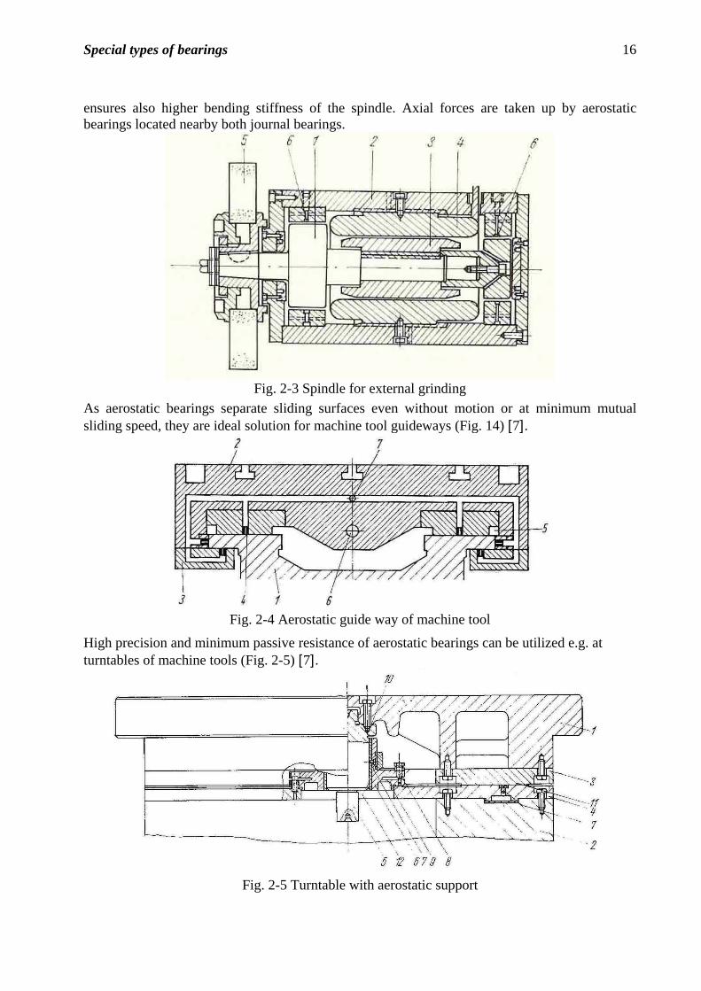
Grinding spindle for external grinding [8] could have substantially lower speed due to greater grinding wheel diameter. Fig. 2-3 presents electrically driven spindle for speed of 1500 rpm. With regard to higher load, the bearing at the grinding wheel side has greater diameter. This
Special types of bearings 16
ensures also higher bending stiffness of the spindle. Axial forces are taken up by aerostatic bearings located nearby both journal bearings.
Fig. 2-3 Spindle for external grinding
As aerostatic bearings separate sliding surfaces even without motion or at minimum mutual sliding speed, they are ideal solution for machine tool guideways (Fig. 14) [7].
Fig. 2-4 Aerostatic guide way of machine tool
High precision and minimum passive resistance of aerostatic bearings can be utilized e.g. at turntables of machine tools (Fig. 2-5) [7].
Fig. 2-5 Turntable with aerostatic support
Special types of bearings 17
Application of aerostatic bearings in Czech Republic
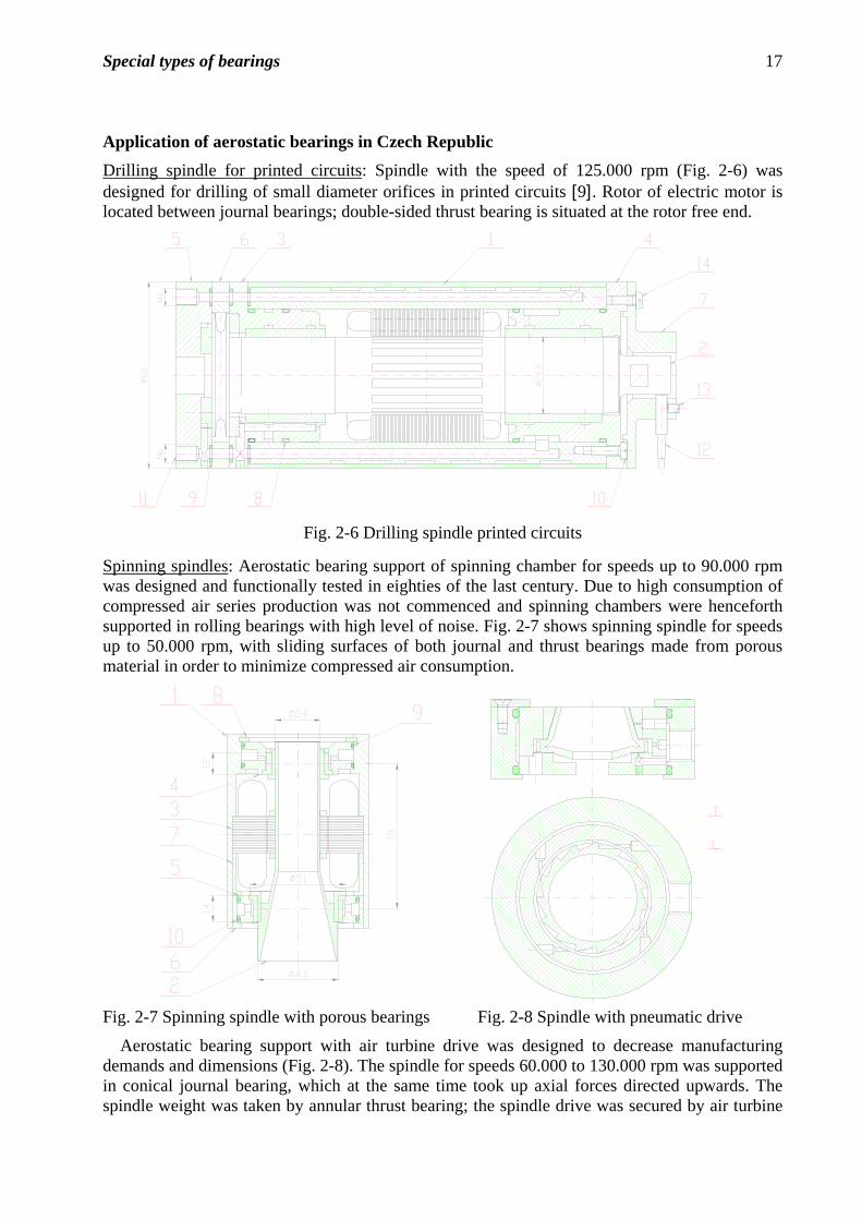
Drilling spindle for printed circuits: Spindle with the speed of 125.000 rpm (Fig. 2-6) was designed for drilling of small diameter orifices in printed circuits [9]. Rotor of electric motor is located between journal bearings; double-sided thrust bearing is situated at the rotor free end.
Fig. 2-6 Drilling spindle printed circuits
Spinning spindles: Aerostatic bearing support of spinning chamber for speeds up to 90.000 rpm was designed and functionally tested in eighties of the last century. Due to high consumption of compressed air series production was not commenced and spinning chambers were henceforth supported in rolling bearings with high level of noise. Fig. 2-7 shows spinning spindle for speeds up to 50.000 rpm, with sliding surfaces of both journal and thrust bearings made from porous material in order to minimize compressed air consumption.
Fig. 2-7 Spinning spindle with porous bearings Fig. 2-8 Spindle with pneumatic drive
Aerostatic bearing support with air turbine drive was designed to decrease manufacturing demands and dimensions (Fig. 2-8). The spindle for speeds 60.000 to 130.000 rpm was supported in conical journal bearing, which at the same time took up axial forces directed upwards. The spindle weight was taken by annular thrust bearing; the spindle drive was secured by air turbine
Special types of bearings 18
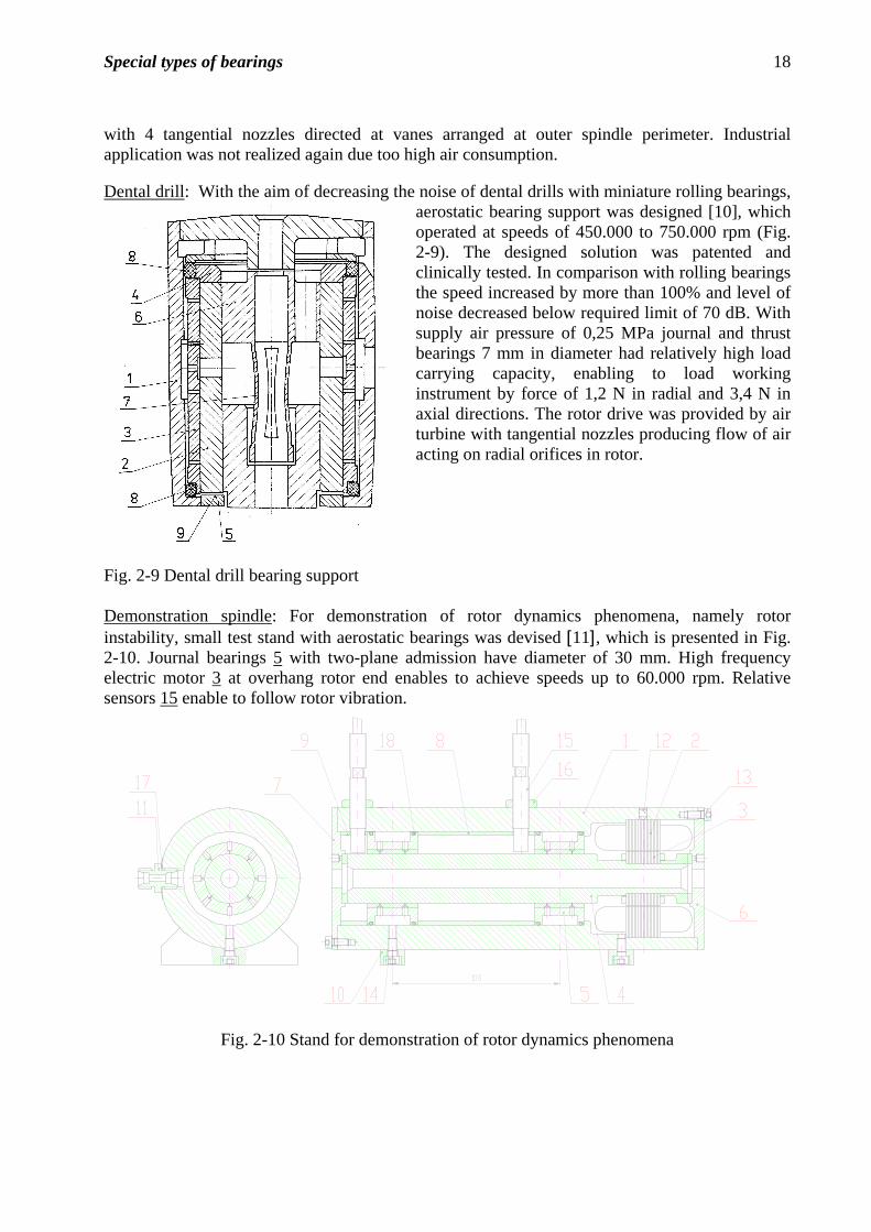
with 4 tangential nozzles directed at vanes arranged at outer spindle perimeter. Industrial application was not realized again due too high air consumption. Dental drill: With the aim of decreasing the noise of dental drills with miniature rolling bearings,
aerostatic bearing support was designed [10], which operated at speeds of 450.000 to 750.000 rpm (Fig. 2-9). The designed solution was patented and clinically tested. In comparison with rolling bearings the speed increased by more than 100% and level of noise decreased below required limit of 70 dB. With supply air pressure of 0,25 MPa journal and thrust bearings 7 mm in diameter had relatively high load carrying capacity, enabling to load working instrument by force of 1,2 N in radial and 3,4 N in axial directions. The rotor drive was provided by air turbine with tangential nozzles producing flow of air acting on radial orifices in rotor.
Fig. 2-9 Dental drill bearing support Demonstration spindle: For demonstration of rotor dynamics phenomena, namely rotor instability, small test stand with aerostatic bearings was devised [11], which is presented in Fig. 2-10. Journal bearings 5 with two-plane admission have diameter of 30 mm. High frequency electric motor 3 at overhang rotor end enables to achieve speeds up to 60.000 rpm. Relative sensors 15 enable to follow rotor vibration.
Fig. 2-10 Stand for demonstration of rotor dynamics phenomena
Special types of bearings 19
III) Magnetic bearings
Analogous to gas bearings magnetic bearings can excellent solution for special operating conditions. The most important feature of magnetic bearings is possibility of active affecting their properties during operation.
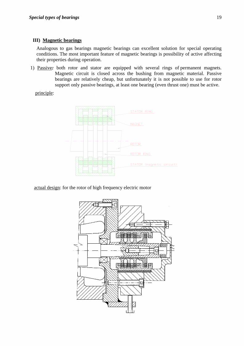
1) Passive: both rotor and stator are equipped with several rings of permanent magnets. Magnetic circuit is closed across the bushing from magnetic material. Passive bearings are relatively cheap, but unfortunately it is not possible to use for rotor support only passive bearings, at least one bearing (even thrust one) must be active.
principle:
actual design: for the rotor of high frequency electric motor
Special types of bearings 20
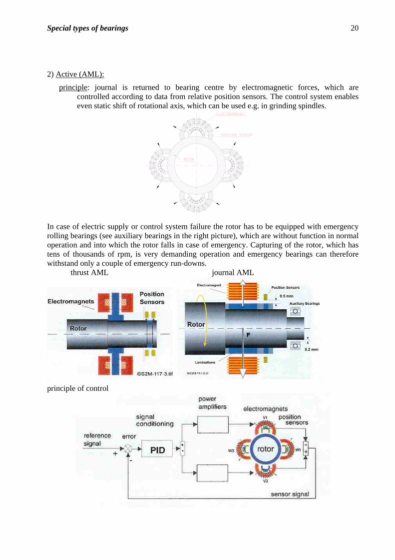
2) Active (AML):
principle: journal is returned to bearing centre by electromagnetic forces, which are controlled according to data from relative position sensors. The control system enables even static shift of rotational axis, which can be used e.g. in grinding spindles.
In case of electric supply or control system failure the rotor has to be equipped with emergency rolling bearings (see auxiliary bearings in the right picture), which are without function in normal operation and into which the rotor falls in case of emergency. Capturing of the rotor, which has tens of thousands of rpm, is very demanding operation and emergency bearings can therefore withstand only a couple of emergency run-downs.
thrust AML journal AML
principle of control
Special types of bearings 21
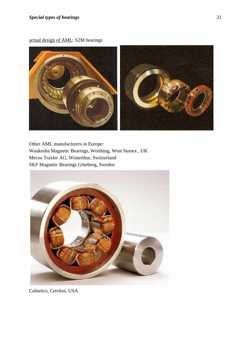
actual design of AML: S2M bearings
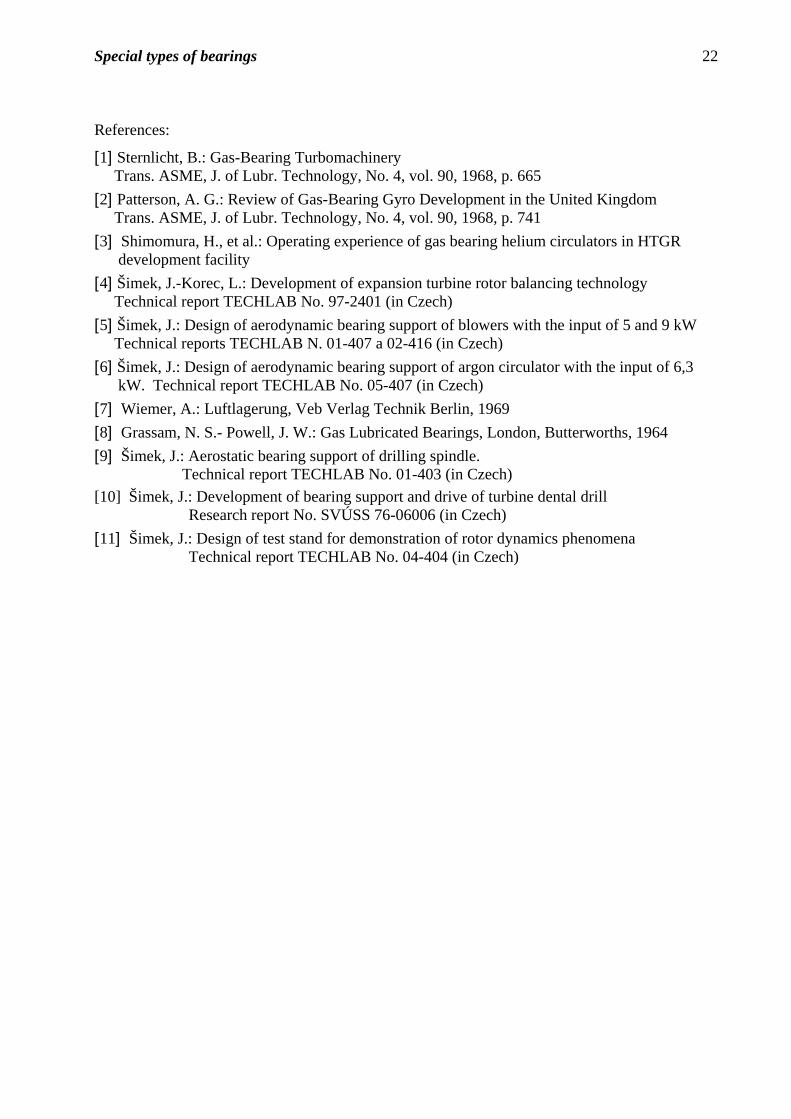
Other AML manufacturers in Europe:
Waukesha Magnetic Bearings, Worthing, West Sussex , UK
Mecos Traxler AG, Winterthur, Switzerland
SKF Magnetic Bearings Göteborg, Sweden
Calnetics, Cerritos, USA
Special types of bearings 22
References:
[1] Sternlicht, B.: Gas-Bearing Turbomachinery Trans. ASME, J. of Lubr. Technology, No. 4, vol. 90, 1968, p. 665
[2] Patterson, A. G.: Review of Gas-Bearing Gyro Development in the United Kingdom Trans. ASME, J. of Lubr. Technology, No. 4, vol. 90, 1968, p. 741
[3] Shimomura, H., et al.: Operating experience of gas bearing helium circulators in HTGR development facility
[4] Šimek, J.-Korec, L.: Development of expansion turbine rotor balancing technology Technical report TECHLAB No. 97-2401 (in Czech)
[5] Šimek, J.: Design of aerodynamic bearing support of blowers with the input of 5 and 9 kW Technical reports TECHLAB N. 01-407 a 02-416 (in Czech)
[6] Šimek, J.: Design of aerodynamic bearing support of argon circulator with the input of 6,3 kW. Technical report TECHLAB No. 05-407 (in Czech)
[7] Wiemer, A.: Luftlagerung, Veb Verlag Technik Berlin, 1969
[8] Grassam, N. S.- Powell, J. W.: Gas Lubricated Bearings, London, Butterworths, 1964
[9] Šimek, J.: Aerostatic bearing support of drilling spindle. Technical report TECHLAB No. 01-403 (in Czech)
[10] Šimek, J.: Development of bearing support and drive of turbine dental drill Research report No. SVÚSS 76-06006 (in Czech)
[11] Šimek, J.: Design of test stand for demonstration of rotor dynamics phenomena Technical report TECHLAB No. 04-404 (in Czech)