this manual must always be kept near the...
TRANSCRIPT

X�RAY EQUIPMENT FOR DENTAL INTRA�ORAL RADIOGRAPHY
INSTALLATION & MAINTENANCE MANUAL
THIS MANUAL MUST ALWAYS BE KEPT NEAR THE MEDICAL DEVICE
X�MIND unity � Installation & Maintenance
Page 2 of 110
DETAILS OF THE DOCUMENT
File name: X�MIND_unity_Installation&ma
Type of document: XMIIND unity xray sys
Edition Revision
1 3c
Language of the original document: ENGLIS
Important: All new editions and revisions
�
Refer to complete manuals and instructions�
ce manual �
XM_unity_Installation&Maintenan
maintenance_Manual_1.3c.docx�
system installation & maintenance manual.
Date Issued by Reviewed
20130605 PM CG
LISH
ns of the manuals supersede the previous ones
� �
For complete manuals and instructions
www.satelec.com/documents
Scan the Qded
www.sate
ance_Manual Ed.1.3c2013
ed by Approved by
MdG
e QR code to access the edicated website atelec.com/documents

� Installation & Maintenance manual � X�MIND unity
XM_unity_Installation&Maintenance_Manual Ed.1.3c2013 Page 3 of 110
MANUFACTURER:
de Götzen S.r.l. � a company of ACTEON Group
Via Roma, 45
21057 OLGIATE OLONA (VA) – ITALY
Tel. +39 0331 376760
Fax +39 0331 376763
Website: www.degotzen.com www.acteongroup.com
Email: [email protected] (for generic requests)
For technical support:
Tech. Support Webpage:
http://support.degotzen.net
https://support.degotzen.net
ITALY
For information and technical assistance, contact the manufacturer
Direct Tel.: +39 0331 376762
WORLDWIDE
Contact your authorised local dealer.
Refer to the list in the following page to find the authorised dealer near you.
X�MIND unity � Installation & Maintenance manual �
Page 4 of 110 XM_unity_Installation&Maintenance_Manual Ed.1.3c2013
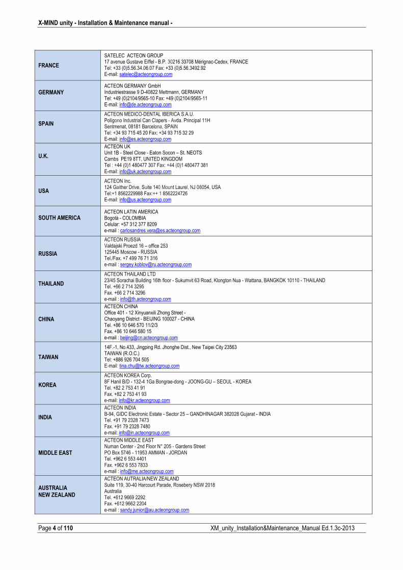
FRANCE
SATELEC ACTEON GROUP 17 avenue Gustave Eiffel B.P. 30216 33708 MérignacCedex, FRANCE Tel: +33 (0)5.56.34.06.07 Fax: +33 (0)5.56.3492.92 Email: [email protected]
GERMANY
ACTEON GERMANY GmbH Industriestrasse 9 D40822 Mettmann, GERMANY Tel: +49 (0)2104/956510 Fax: +49 (0)2104/956511 Email: [email protected]
SPAIN
ACTEON MEDICODENTAL IBERICA S.A.U. Polígono Industrial Can Clapers Avda. Principal 11H Sentmenat, 08181 Barcelona, SPAIN Tel: +34 93 715 45 20 Fax: +34 93 715 32 29 Email: [email protected]
U.K.
ACTEON UK Unit 1B Steel Close Eaton Socon – St. NEOTS Cambs PE19 8TT, UNITED KINGDOM Tel : +44 (0)1 480477 307 Fax: +44 (0)1 480477 381 Email: [email protected]
USA
ACTEON Inc. 124 Gaither Drive, Suite 140 Mount Laurel, NJ 08054, USA Tel:+1 8562229988 Fax:++ 1 8562224726 Email: [email protected]
SOUTH AMERICA
ACTEON LATIN AMERICA Bogotà COLOMBIA Celular: +57 312 377 8209 email : [email protected]
RUSSIA
ACTEON RUSSIA Valdajski Proezd 16 – office 253 125445 Moscow RUSSIA Tel./Fax. +7 499 76 71 316 email : [email protected]
THAILAND
ACTEON THAILAND LTD 23/45 Sorachai Building 16th floor Sukumvit 63 Road, Klongton Nua Wattana, BANGKOK 10110 THAILAND Tel. +66 2 714 3295 Fax. +66 2 714 3296 email : [email protected]
CHINA
ACTEON CHINA Office 401 12 Xinyuanxili Zhong Street Chaoyang District BEIJING 100027 CHINA Tel. +86 10 646 570 11/2/3 Fax. +86 10 646 580 15 email : [email protected]
TAIWAN
14F.1, No.433, Jingping Rd. Jhonghe Dist., New Taipei City 23563 TAIWAN (R.O.C.) Tel: +886 926 704 505 Email: [email protected]
KOREA
ACTEON KOREA Corp. 8F Hanil B/D 1324 1Ga Bongraedong JOONGGU – SEOUL KOREA Tel. +82 2 753 41 91 Fax. +82 2 753 41 93 email: [email protected]
INDIA
ACTEON INDIA B94, GIDC Electronic Estate Sector 25 – GANDHINAGAR 382028 Gujarat INDIA Tel. +91 79 2328 7473 Fax. +91 79 2328 7480 email: [email protected]
MIDDLE EAST
ACTEON MIDDLE EAST Numan Center 2nd Floor N° 205 Gardens Street PO Box 5746 11953 AMMAN JORDAN Tel. +962 6 553 4401 Fax. +962 6 553 7833 email : [email protected]
AUSTRALIA NEW ZEALAND
ACTEON AUTRALIA/NEW ZEALAND Suite 119, 3040 Harcourt Parade, Rosebery NSW 2018 Australia Tel. +612 9669 2292 Fax. +612 9662 2204 email : [email protected]
� Installation & Maintenance manual � X�MIND unity
XM_unity_Installation&Maintenance_Manual Ed.1.3c2013 Page 5 of 110
THE ELECTROMEDICAL EQUIPMENT DESCRIBED IN THIS MANUAL REFERS TO THE X�MIND unity MEDICAL DEVICE.
“de Götzen® S.r.l. ACTEON Group” RESERVES THE RIGHT TO MODIFY THE PRODUCT AND ALL THE MANUALS WITHOUT
PRIOR NOTICE.
IT IS PROHIBITED TO MODIFY, COPY, REPRODUCE, DISPLAY, SHARE, DISCLOSE AND PUBLISH THIS MANUAL AND ALL
OTHER DOCUMENTS REFERRING TO X�MIND unity IN ANY FORM WITHOUT PRIOR WRITTEN CONSENT BY de GÖTZEN®
S.R.L. ACTEON Group
THIS MANUAL MUST ALWAYS BE KEPT NEAR THE MEDICAL DEVICE FOR FUTURE REFERENCE.
“de Götzen® S.r.l. � ACTEON Group” SHALL NOT BE HELD LIABLE FOR MISUSE OF THE INFORMATION PROVIDED BY
THIS MANUAL.

X�MIND unity � Installation & Maintenance manual �
Page 6 of 110 XM_unity_Installation&Maintenance_Manual Ed.1.3c2013
TABLE OF CONTENTS
TABLE OF CONTENTS _____________________________________________________________________________________6
1. INTRODUCTION ______________________________________________________________________________________9
���� ����������� ������������������������������������������������������������������������������
���� � ������� ���������������������������������������������������������������������������������
���������������������� �����������������������������������������������������������������������������
����������������������������������������������������������������������������������������������������
������� ���������������������������������������������������������������������������������������������
���������������������������� ������������������ !"��#$%&'(')� �����������������������������������*
2. RADIOGRAPHIC SYSTEM OVERVIEW___________________________________________________________________18
�������������������������������������������������������������������������������������������������+
���� ����� �����������������������������������������������������������������������������������������
3. INSTALLATION REQUIREMENTS _______________________________________________________________________23
���� �,������������������������������������������������������������������������������������� CLINICAL ENVIRONMENT CONDITIONS (OPERATING CONDITIONS) _________________________________________23 TRANSPORTATION ENVIRONMENT CONDITIONS _________________________________________________________23 WAREHOUSING ENVIRONMENT CONDITIONS ___________________________________________________________23
���� ������������ �����������������������������������������������������������������������������
���� ������������ �����������������������������������������������������������������������������
���� ������������ �������������������������������������������������������������������������������
���� �������������������� �����������������������������������������������������������������������
4. INSTALLATION POSSIBILITIES ________________________________________________________________________27
���� �� ����������-����������������������������������������������������������������������������*
���� �,������������������������������������������������������������������������������������������ 4.2.1. FRONT VIEW (REST POSITION) BOTTOM MOUNT _______________________________________________29 4.2.2. FRONT VIEW (REST POSITION) TOP MOUNT ___________________________________________________29 4.2.3. SIDE VIEW (OPEN) TOP MOUNT _____________________________________________________________30 4.2.4. SIDE VIEW (CLOSED) TOP MOUNT ___________________________________________________________31 4.2.5. SIDE VIEW (OPEN) BOTTOM MOUNT _________________________________________________________32 4.2.6. SIDE VIEW (CLOSED) BOTTOM MOUNT _______________________________________________________33
5. INSTALLATION______________________________________________________________________________________34
���� ����.�����������������������������������������������������������������������������������������
���� ����/������������0�����/���.��� �����������������������������������������������������������
���� ����/������������������� �������������������������������������������������������������������
���� �������������������� ����������������������������������������������������������������������� 5.5.1. OVERVIEW OF THE INTERNAL PARTS OF THE TIMER ____________________________________________61 5.5.2. STEP 1 CABLES ROUTING IN THE WALL PLATE: ________________________________________________62 5.5.3. STEP 2 CONNECTING INPUT POWER BOARD and INTERFACE BOARD: ____________________________63

� Installation & Maintenance manual � X�MIND unity
XM_unity_Installation&Maintenance_Manual Ed.1.3c2013 Page 7 of 110
5.5.4. STEP 3 GROUND POINT CONNECTION ON THE WALL PLATE: ____________________________________64 5.5.5. STEP 4 INSTALL AND CONNECT REMOTE EXPOSURE SWITCH AND XMIND unity LIGHT (Optional) _____65 5.5.6. STEP 5 CONNECTING CONTROL POWER BOARD: ______________________________________________65 5.5.7. STEP 6 CONTROL BOX CONNECTIONS CHECK ________________________________________________66 5.5.8. STEP 7 CONNECTING CONTROL DISPLAY BOARD ______________________________________________68 5.5.9. STEP 8 ASSEMBLING THE TIMER: ____________________________________________________________69
6. INSTALL AND CONNECT X�MIND unity LIGHT (OPTIONAL) _________________________________________________70
7. INSTALL AND CONNECT THE REMOTE EXPOSURE SWITCH (OPTIONAL) ____________________________________73
6. START UP __________________________________________________________________________________________75
7. CONFIGURATION____________________________________________________________________________________77
*��� ��,���������������� ���,�������)�������������������������������������������������������*�
8. CHECKING THE INSTALLATION _______________________________________________________________________81
+��� ����.��������� ��������������������������������������������������������������������������+�
+��� ����.�������������������������������������������������������������������������������������+�
+��� ����.��������-�����������������������������������������������������������������������������+�
+��� ����.����������������� �������/����������������������������������������������������������+�
+��� ����.��������/���/������������������������������������������������������������������������+�
+��� ����.���������������������� ���������������������������������������������������������������+�
9. BASICAL CHECKING OVERALL SYSTEM FUNCTIONS _____________________________________________________83
10. CHECKING THE EXPOSURE FACTORS _______________________________________________________________84
����� ����.�������-1������/��,������� 2,)� ������������������������������������������������������+�
����� ����.�������-1������/��������� 3�)�������������������������������������������������������+�
11. DIAGNOSTIC _____________________________________________________________________________________87
����� -1��������/������������������������������������������������������������������������������+*
12. ERROR MESSAGES _______________________________________________________________________________88
13. SUGGESTED MAINTENANCE AND REPAIR ____________________________________________________________91
����� �������������������� ���������������������������������������������������������������������
����� ����������������������������������������������������������������������������������������������
����� ��������������������������������������������������������������������������������������
����� ����������� � ����������������������������������������������������������������������������
����� �����������/������������,���� �!%%435"!6��!#()���������������������������������������������� 13.5.1. ROUND CONE (SHORT AND LONG) ____________________________________________________________96 13.5.2. RECTANGULAR CONE _______________________________________________________________________97 13.5.3. MODIFY INSTALLED BEAM LIMITING DEVICE IN XMIND unity CONTROL UNIT _______________________100
����� ��������������/���������/������������������������������������������������������������������
���*� �������6(1����/���������/������� �����������������������������������������������������������

X�MIND unity � Installation & Maintenance manual �
Page 8 of 110 XM_unity_Installation&Maintenance_Manual Ed.1.3c2013
14. TECHNICAL SPECIFICATIONS ______________________________________________________________________105
15. ELECTRICAL SCHEMES ___________________________________________________________________________106
-1���"7��%!85%��464#9��$:(3(���������������������������������������������������������������������������
� Installation & Maintenance manual � X�MIND unity
XM_unity_Installation&Maintenance_Manual Ed.1.3c2013 Page 9 of 110
1. INTRODUCTION
1.1. PRELIMINARY INFORMATIONS
Before starting with the use of the “X�MIND unity” xray system, it is mandatory to carefully read and follow the instructions contained
herein in order to obtain the best performance and assure the safety of the patient, operator, device and the environment.
Always pay close attention to the messages when operating the system.
CAUTION
WARNING
PLEASE NOTE
LEGEND
CAUTION
���� ����� ��� �� ����������� ������ ������������ ������ ������ ����������� ���� ����������� ��������� ������� ��� ������
��������������������
WARNING
���������� ���!���������������������������������������������������������"#��������������������������
PLEASE NOTE
$%&'&�� �&����(��������(�����������������������������������������������������)���������������������������������
X�MIND unity � Installation & Maintenance manual �
Page 10 of 110 XM_unity_Installation&Maintenance_Manual Ed.1.3c2013
1.2. INFORMATION FOR THE INSTALLER
CAUTION � WARNING
�������������������������*�����������������������+��������������������������������������������������
The XMIND unity is an Xray equipment intended to be used for dental intraoral xray imaging.
For a safe and reliable installation of the XMIND unity radiographic system, together with the strict following of the
instructions and recommendations contained in the accompanying documents and provided by the manufacturer, it is further
recommended to:
Check that the rated voltage mentioned in the rating plates matches the line voltage.
Install the radiographic system according to the procedures described in this manual and in compliance with local
rules and laws of the place of installation.
Provide the operator with any information regarding the use of the radiographic system according to what stated
in the accompanying documents according to its intended use.
Certify the work done by a “declaration of conformity”.
This manual has been written and published under the supervision of de Götzen® S.r.l. ACTEON Group. It contains all the latest
descriptions and features of the product. Although every effort is made to produce uptodate and multilanguage documentation
(since each accompanying document is translated in different languages), this publication should not be regarded as an infallible
guide to current specifications.
The information in this manual is periodically updated; any amendment will be included in subsequent publications without prior
notice by de Götzen® S.r.l. ACTEON Group.
Contact your dealer to request the latest version of the manual.
In the event of errors, please inform de Götzen® S.r.l. ACTEON Group promptly.
CAUTION � WARNING
This manual describes how to install and set the X�MIND unity x�ray system.
The installer must read and understand the manual before install and set the medical device.
This manual must be always kept as a reference document and it is mandatory to comply with the instructions supplied
with it.
Before install the device, it is essential to carefully read the instructions, CAUTION and WARNING messages listed in the
paragraph relevant to the safety warnings.
CAUTION – WARNING
This manual does not include all the recommendations and obligations concerning installation and use of ionising
radiation sources, since they differ from country to country. Therefore, only the most common are listed
Installers must refer to the laws in force in their country to meet all legal requirements.
� Installation & Maintenance manual � X�MIND unity
XM_unity_Installation&Maintenance_Manual Ed.1.3c2013 Page 11 of 110
PLEASE NOTE
For installation in USA, a report of assembly (Form FDA 2579) must be filled out to certify that the medical equipment was
assembled according to the instructions provided by the manufacturer, and meets the requirements of the applicable
Federal standards contained in 21 CFR 1020.30 through 1020.33.
Reports must be filed with FDA's Center for Devices and Radiological Health (CDRH) within 15 days of completion of the
assembly. The report must be filled in according to the methods provided in:
http://www.fda.gov/ForIndustry/FDAeSubmitter/ucm107879.htm
(remember to check the updated web address since this may change over time)
1.3. WARRANTY CONDITIONS
Inappropriate use or any arbitrary tampering with, exempt “de Götzen® S.r.l. ACTEON Group”, as manufacturer of the “XMIND
unity” xray system, from any service under warranty or from any other liability.
The warranty is valid only if the following precautions are taken, please refer also to the warranty conditions:
- Any repair, modification, adjustment, or any kind of technical intervention must be performed only by de Götzen
S.r.l. or by a qualified authorized representative
- The installation must be made by professionally qualified technicians according to the regulations in force.
- The system must be installed and used in compliance with the instructions given in this operator’s manual and in its
associated documentation.
- The device shall be used in compliance with the purposes and applications for which it is designed.
- The power supply must be adequate to supply the required power indicated in the data contained in the labels of the
device.
- In order to safeguard your warranty rights, read carefully, fill and sign the Warranty Document provided by the
seller, immediately after the installation is completed, together with the installer.
- The system must be checked completely at least each 12 months by professionally qualified technicians according to the
regulations in force. Use the manuals provided with the device X�MIND unity for reference.
- de Götzen S.r.l. refuse all responsibility due to any damage coming from persons or things in consequence of nonobservance of all prescriptions contained in all the manuals provided with the X�MIND unity device.
- In case of repair, only original spare parts of the manufacturer of the X�MIND unity must be used.
CAUTION
Disregarding the above mentioned rules and all the indications provided by the manufacturer in the documentation, or successively in written paper or electronic format, will cause the total losing of the warranty of the product and the manufacturer will be discharged from any obligation, including consequential damages, direct or indirect that may derive to people, things or environment. Furthermore, the facility representative, customer or employees of the facility, will be liable for any damage and/or incident and/or degeneration of the health status of a patient, operator, involved people and the surrounding environment.
This also will have the result in service charges for nonwarranty technical assistance.
X�MIND unity � Installation & Maintenance manual �
Page 12 of 110 XM_unity_Installation&Maintenance_Manual Ed.1.3c2013
1.4. TRANSPORT CONDITIONS
������������������������The “X�MIND unity” x�ray system travels at the receiver’s own risk���
All claims for damages or mishaps regarding the shipment must be pointed out in the presence of the shipping agent. In case of actual or suspected damages, the receiver shall indicate the proper reserves on the waybill or on the consignment note.
1.5. SAFETY WARNINGS
A few safety recommendations are listed here below which must be followed when using the “X�MIND unity” xray system.
CAUTION
GENERAL REQUIREMENTS
• The Installation of the X�MIND unity system must be executed only by trained, qualified and authorized service
personnel.
• de Götzen S.r.l. � ACTEON Group or its authorized technicians are not allowed to check the conformity of the
installation site with the local laws and regulations in terms of Electrical safety, X�ray protection or any kind of
safety regulations of the country and location where the X�MIND unity is installed.
• The X�MIND unity must be installed and operated in accordance with the safety procedures and operating
instructions given in the Operator’s manual, Installation & Maintenance manual and Maintenance Manual and
all the connected accompanying documents for the purposes and intended use for which it was designed.
• It is mandatory for the RESPONSIBLE ORGANIZATION to provide a routine and special maintenance schedule
for biomedical equipment; this schedule must be documented for every device and transmitted to the various
operating levels (*).The preventive maintenance (that must be performed at least every twelve months), which
includes functional, performance and safety tests of the device, must be carried out by qualified, authorised
professional technicians, it is mandatory to ensure patients' health and safety and proper X�MIND unity
operation (IEC 60601�1 etc.).These operations must be carried out according to the methods and frequency
indicated in this manual, in the installation and maintenance manual and maintenance manual. Failure to
comply with this requirement or with the messages concerning anomalies will release the manufacturer from
any liability for direct and indirect injuries to persons and/or damage to property or the environment.
Furthermore, the managers of the facility, customers or collaborators shall be held liable for any damage
and/or accidents and/or degeneration of patients' or operators' health or of the surrounding environment.
The RESPONSIBLE ORGANIZATION must also provide for the safe and proper use of the equipment.
(*) For Italy refer to Presidential Decree 14/01/1997, Legislative Decree No. 81/2008 (as subsequently amended
and modified).
• Carefully follow the instructions in this manual and the accompanying documents to install and proper
maintain and use the X�MIND unity device. In the event that local laws and standards are more restrictive than
the manufacturer's indications, the former supersede the latter.
• The installation and placing in service of the X�MIND unity must comply with the standards and regulations in
force concerning the installation of the medical device in consideration of the place and country of installation.
• The X�MIND unity must be installed in order that the operator must be able to monitor the patient throughout
the entire duration of the x�ray examination.
� Installation & Maintenance manual � X�MIND unity
XM_unity_Installation&Maintenance_Manual Ed.1.3c2013 Page 13 of 110
• It is prohibited to modify or attempt to repair the electronic boards of the X�MIND unity.
• de Götzen S.r.l. � ACTEON Group and its authorised technicians are not required to verify compliance of the
installation site with local standards concerning electrical safety and X�ray protection and with any other
directive concerning safety in force in the country of installation.
• The RESPONSIBLE ORGANIZATION of the X�MIND unity must ensure compliance of the installation site
with the local laws in force
CAUTION
INSTALLATION OF THE SOPIX/SOPIX2 INSIDE INTRAORAL X�RAY DIGITAL SENSOR
• The X�MIND unity is already partially prepared for the integration only of the optional Sopix/Sopix2 Inside
intraoral x�ray digital sensors manufactured by Sopro�Acteon Group.
For the proper and safe installation of the Sopix/Sopix2 Inside sensor it is mandatory to strictly follow the
instructions and accompanying documents relevant to the Sopix/Sopix2 Inside and all the recommendations
contained in the accompanying documents relevant to the X�MIND unity.
• The X�MIND unity has been certified by Accredited Laboratories ONLY for the integrated use with the
Sopix/Sopix2 Inside x�ray digital intraoral sensor, according to the requirements stated by the applicable
standards. It is strictly forbidden to connect, trying to connect or operate in any way devices different from the
Sopix/Sopix2 Inside sensor manufactured by Sopro. If you don’t respect this warning the overall safety of the
X�MIND unity can be irreversibly compromised with the consequence of damages or injuries to patients, to
operators and to the environment. Failure to comply with this requirement or with the messages concerning
the presence of eventual anomalies will release the manufacturer from any liability for direct and indirect
injuries to persons and/or damage to property or the environment. Furthermore, the managers of the facility,
customers or collaborators shall be held liable for any damage and/or accidents and/or degeneration of
patients' or operators' health or of the surrounding environment.
X�MIND unity � Installation & Maintenance manual �
Page 14 of 110 XM_unity_Installation&Maintenance_Manual Ed.1.3c2013
CAUTION
$ �&�� ��!��'�� ,��� �'�
The "General principles for safeguarding and protecting the personnel and patients" must always be applied during the
use of the X�ray unit.
1. Justification of the practice
2. Optimisation of protection principle (ALARA principle)
3. Individual risk and dose limits
• The X�MIND unity is a medical device that generates X�rays; therefore, both the patients and the operator are
exposed to risks due to ionising radiation. The physician must assess the actual need for X�ray exposure.
• All personnel present during x�ray examination must comply with safety regulations concerning protection
against radiation. For his own safety, the operator must always keep a distance of more than 2 meters (6 ft.)
from the x�ray beam.
• The X�MIND unity medical device must be installed and used in compliance with the local standards in force
and with the international directives concerning radiation protection.
• Comply with the guidelines and indications provided by an accredited specialist in radiation protection, who
will recommend, if necessary, the additional shields or precautions for every specific case.
• The device installation site must be shielded in compliance with the local standards in force to protect the
operator, patient and other people against X�rays.
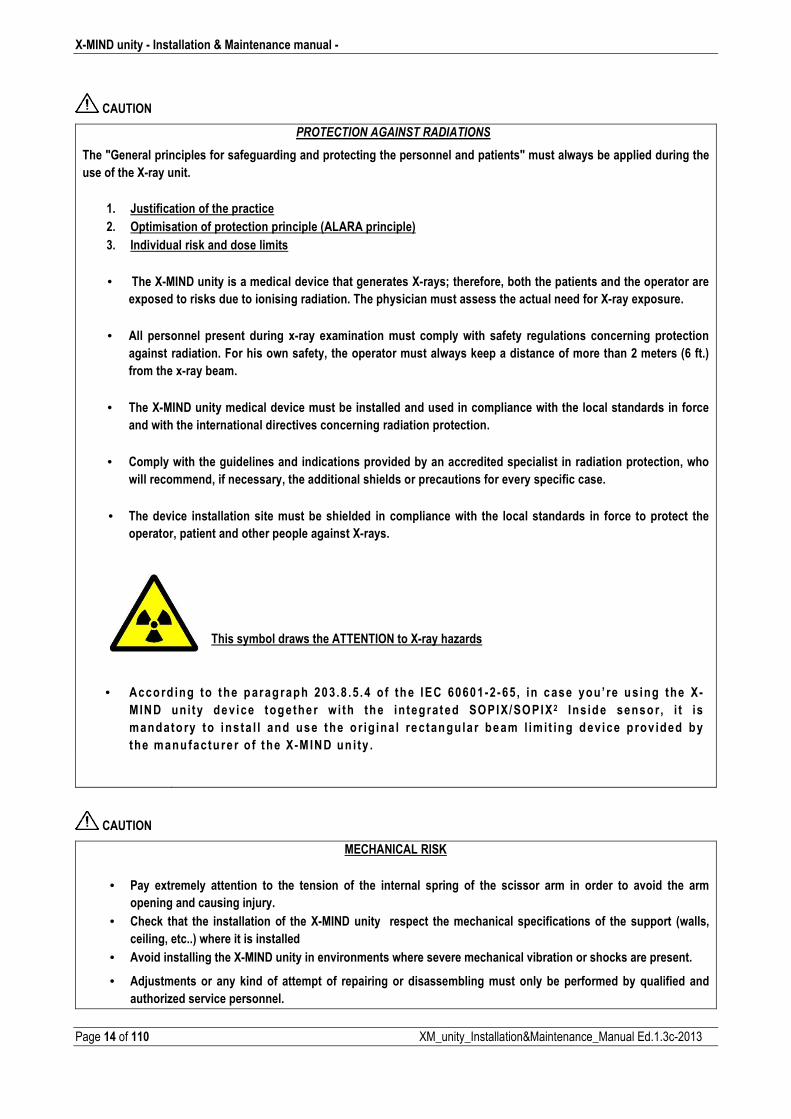
�
�
This symbol draws the ATTENTION to X�ray hazards
• Accord ing to the paragraph 203.8 .5 .4 o f the IEC 60601�2�65 , in case you’ re using the X�
MIND uni ty device together wi th the in tegrated SOPIX/SOPIX 2 Ins ide sensor, i t is
mandato ry to insta l l and use the o r ig ina l rectangula r beam l imi t ing device p rov ided by
the manufactu re r o f the X�M IND un i ty .
� �
CAUTION
MECHANICAL RISK
• Pay extremely attention to the tension of the internal spring of the scissor arm in order to avoid the arm
opening and causing injury.
• Check that the installation of the X�MIND unity respect the mechanical specifications of the support (walls,
ceiling, etc..) where it is installed
• Avoid installing the X�MIND unity in environments where severe mechanical vibration or shocks are present.
• Adjustments or any kind of attempt of repairing or disassembling must only be performed by qualified and
authorized service personnel.
� Installation & Maintenance manual � X�MIND unity
XM_unity_Installation&Maintenance_Manual Ed.1.3c2013 Page 15 of 110
CAUTION
ELECTRICAL SAFETY
• The x�ray system contains high voltage. It’s not allowed to inspect internal parts of the system.
• Never attempt to open the x�ray source.
• The covers on the X�MIND unity equipment must only be removed by qualified and authorized service
personnel.
• The unit must be installed only in environments that are in compliance with all the electrical safety standards
set forth for medical environments.
• The unit is NOT equipped with protections against penetration of liquids; it will therefore be necessary to make
sure that no water or other liquids penetrate inside so as to avoid short circuits or corrosion.
• Always disconnect the x�ray system from the power supply and wait for 2 minutes before beginning cleaning or
disinfecting operations or maintenance.
• Do not connect a multiple portable socket outlet (MPSO) or extension cord to the system.
• External equipment intended for connection to signal input, signal output or other connectors shall comply
with the relevant product standard e.g. IEC 60950�1 for IT equipment and the IEC 60601�series for medical
electrical equipment. In addition, all such combinations – systems – shall comply with the safety requirements
stated in the collateral standard IEC 60601�1�1 or the general standard IEC 60601�1, edition 3, clause 16. Any
equipment not complying with the leakage current requirements in IEC 60601�1 shall be kept outside the
patient environment i.e. at least 1.5 m from the patient support.
• Any person who connects external equipment to signal input, signal output or other connectors has formed a
system and is therefore responsible for the system to comply with the requirements. If in doubt, contact
qualified medical technician or your local representative.
• An isolation device (Separation Device) is mandatory needed to isolate the equipment located outside the
patient environment from the equipment located inside the patient environment. In particular such a Separation
Device is required when a network or data connection is made. The requirements on the Separation Device is
defined in IEC 60601�1�1 and in IEC 60601�1, edition 3, clause 16.
• Pay extreme care of the internal cables throughout the whole unit in order not to damage them
• Basing on the IEC 60601�1, the installation of the X�MIND unity wall version is permanent type (fixed). IT IS NOT
ALLOWED TO connect the equipment to the main supply using a plug
• Do not modify or try to modify any internal wiring or connector which are already present and provided in the
X�Mind unity.
X�MIND unity � Installation & Maintenance manual �
Page 16 of 110 XM_unity_Installation&Maintenance_Manual Ed.1.3c2013
WARNING � CAUTION
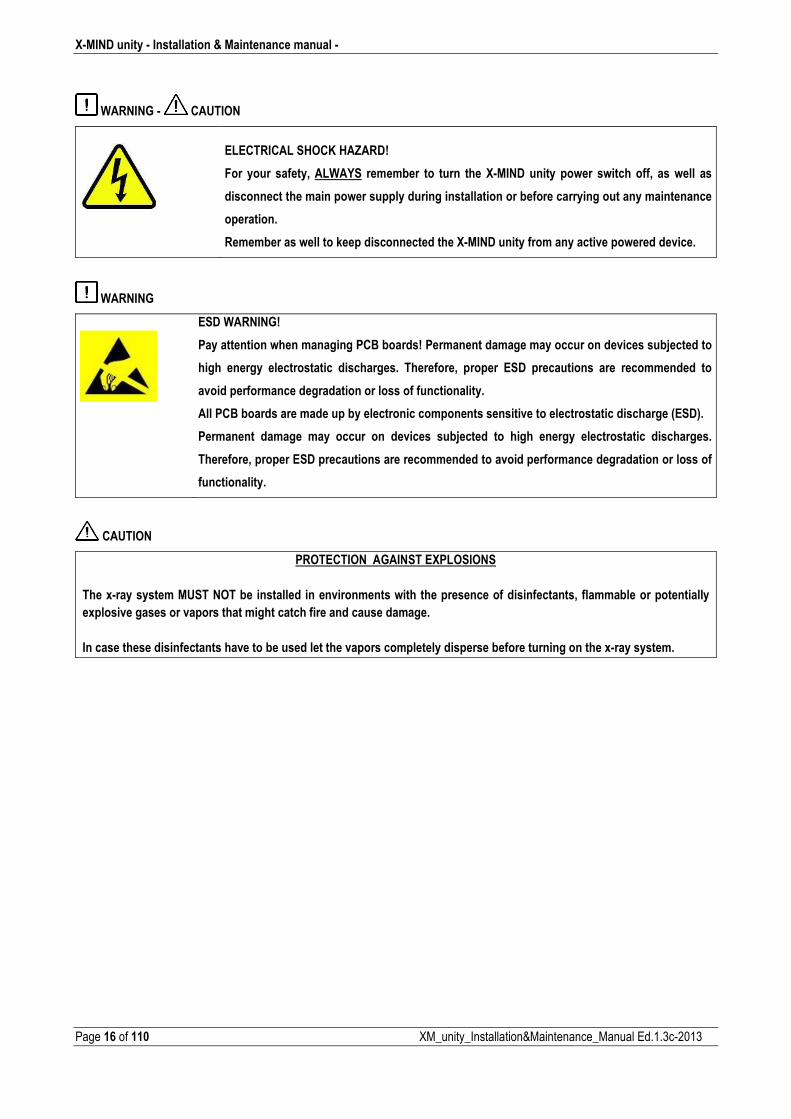
ELECTRICAL SHOCK HAZARD!
For your safety, ALWAYS remember to turn the X�MIND unity power switch off, as well as
disconnect the main power supply during installation or before carrying out any maintenance
operation.
Remember as well to keep disconnected the X�MIND unity from any active powered device.
WARNING
ESD WARNING!
Pay attention when managing PCB boards! Permanent damage may occur on devices subjected to
high energy electrostatic discharges. Therefore, proper ESD precautions are recommended to
avoid performance degradation or loss of functionality.
All PCB boards are made up by electronic components sensitive to electrostatic discharge (ESD).
Permanent damage may occur on devices subjected to high energy electrostatic discharges.
Therefore, proper ESD precautions are recommended to avoid performance degradation or loss of
functionality.
�CAUTION� �
PROTECTION AGAINST EXPLOSIONS
The x�ray system MUST NOT be installed in environments with the presence of disinfectants, flammable or potentially
explosive gases or vapors that might catch fire and cause damage.
In case these disinfectants have to be used let the vapors completely disperse before turning on the x�ray system.�
� Installation & Maintenance manual � X�MIND unity
XM_unity_Installation&Maintenance_Manual Ed.1.3c2013 Page 17 of 110
1.6. EQUIPMENT AND TOOLS NEEDED FOR THE INSTALLATION (Not Included)
For a standard installation of the medical device XMIND unity, the following tools are needed:
1. Drill
2. Wall tips of various size.
3. Paper tape or similar to fix template to the wall.
4. Spirit level.
5. Flexometer.
6. Set of screwdrivers, flat and cross type.
7. Click wrench (suggested dynamometer click wrench to check torque of anchor bolts).
8. Series of metric socket wrenches with extension tube.
9. Series of metric Allen keys.
10. Scissors or cable stripper.
11. Necessary tools and components to install ring and ferrules.
12. True RMS Calibrated Multimeter.

X�MIND unity � Installation & Maintenance manual �
Page 18 of 110 XM_unity_Installation&Maintenance_Manual Ed.1.3c2013
2. RADIOGRAPHIC SYSTEM OVERVIEW
2.1. SYSTEM COMPONENTS
The XMIND unity radiographic system ( 49����) consists of:
Fig.1.1
1. X�RAY CONTROL UNIT (TIMER) and WALL PLATE
2. HORIZONTAL BRACKET
3. PANTOGRAPH TYPE ARM (SCISSOR)
4. X�RAY SOURCE ASSEMBLY (TUBEHEAD)
5. Sopix/Sopix2 Inside SENSOR and SENSOR HOLDER1
6. COLLIMATOR CONE (Beam Limiting Device)
OTHER OPTIONALS
� X�MIND unity REMOTE EXPOSURE SWITCH
� X�MIND unity LIGHT (Rx signalling lamp for external use)
1 Optional Sold Separately. Contact Sopro, ZAC Athélia IV • Avenue des Genévriers • 13705 LA CIOTAT cedex • FRANCE • Tél +33 (0) 442 98 01 01 • Fax +33 (0) 442 71 76 90 • Email: [email protected] • www.sopro.acteongroup.com
� Installation & Maintenance manual � X�MIND unity
XM_unity_Installation&Maintenance_Manual Ed.1.3c2013 Page 19 of 110
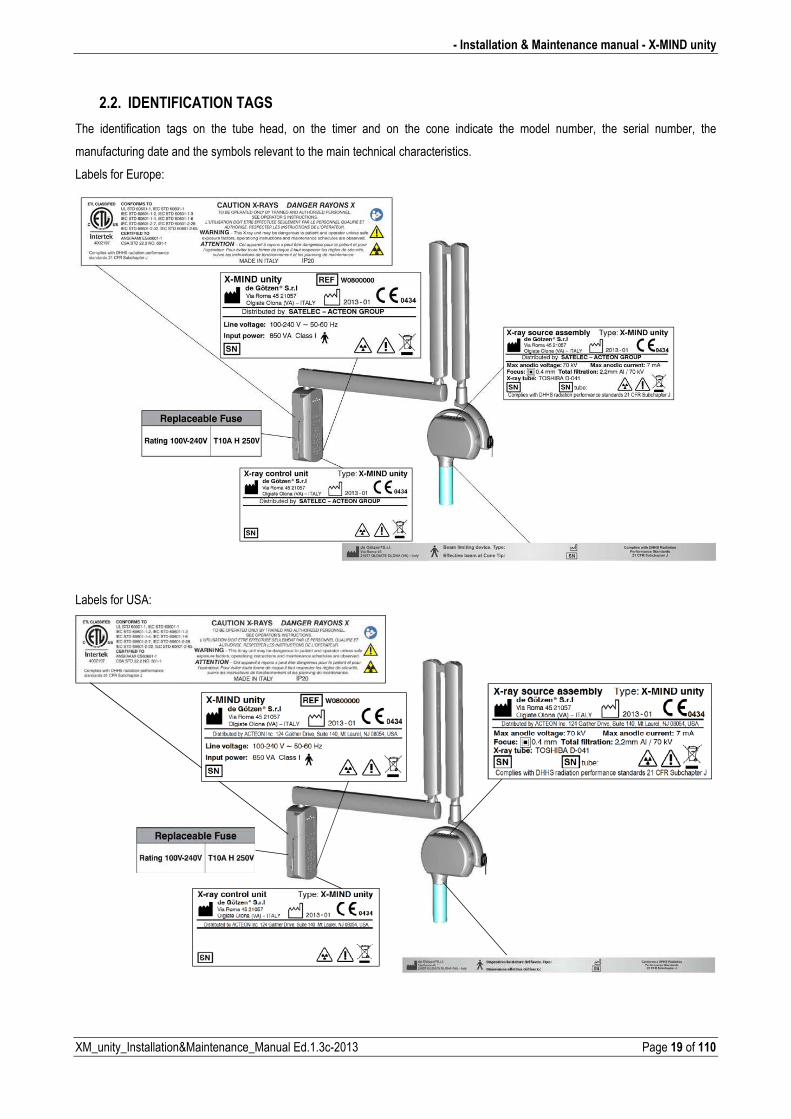
2.2. IDENTIFICATION TAGS
The identification tags on the tube head, on the timer and on the cone indicate the model number, the serial number, the
manufacturing date and the symbols relevant to the main technical characteristics.
Labels for Europe:
Labels for USA:
X�MIND unity � Installation & Maintenance manual �
Page 20 of 110 XM_unity_Installation&Maintenance_Manual Ed.1.3c2013
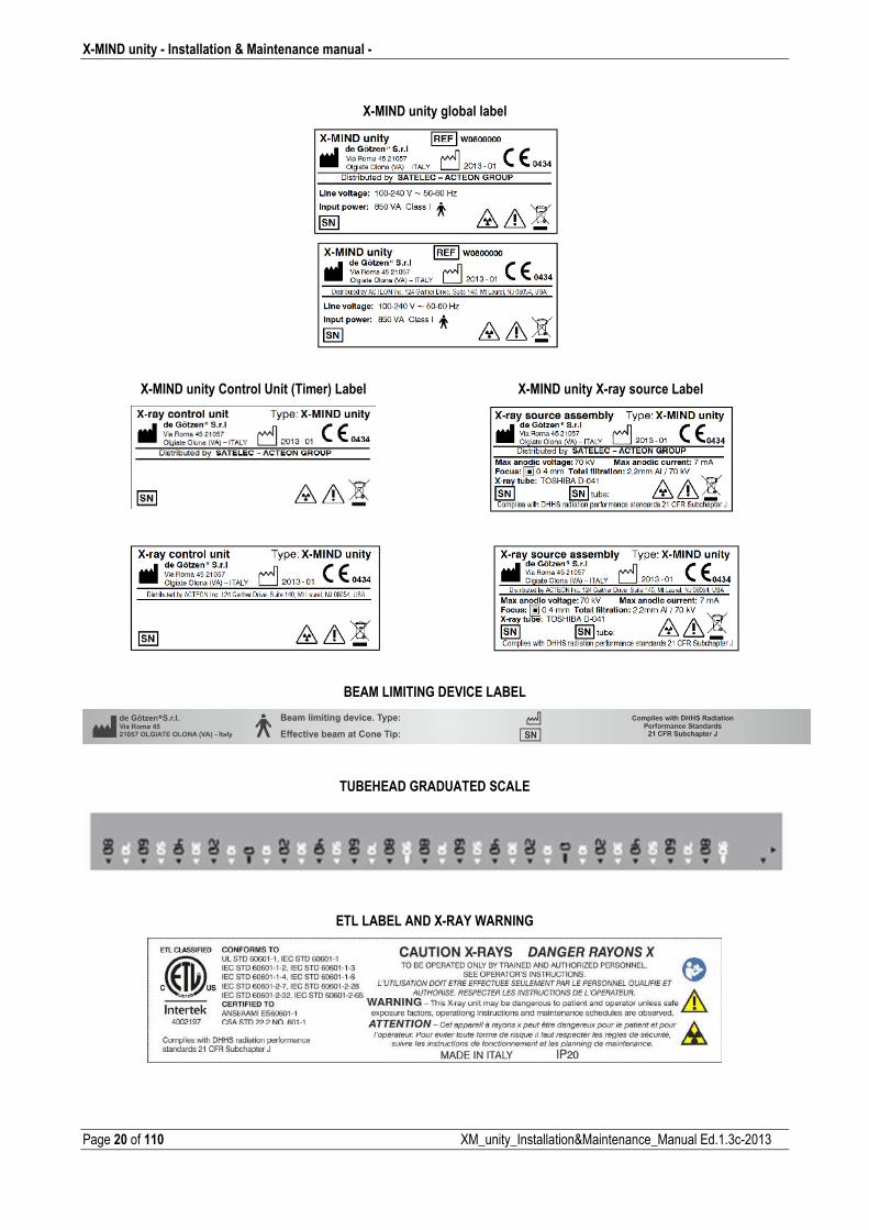
X�MIND unity global label
X�MIND unity Control Unit (Timer) Label X�MIND unity X�ray source Label
BEAM LIMITING DEVICE LABEL
TUBEHEAD GRADUATED SCALE
ETL LABEL AND X�RAY WARNING
XM_unity_Installation&Maintenance_Manual
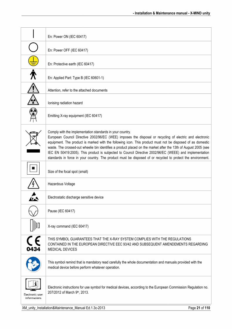
En: Power ON (IEC 60417
En: Power OFF (IEC 6041
En: Protective earth (IEC 6
En: Applied Part: Type B (
Attention, refer to the attac
Ionising radiation hazard
Emitting Xray equipment (
Comply with the implemenEuropean Council Directiequipment. The product iwaste. The crossedout wIEC EN 50419:2005). Thistandards in force in youContact your supplier befo
Size of the focal spot (sma
Hazardous Voltage
Electrostatic discharge sen
Pause (IEC 60417)
Xray command (IEC 6041
THIS SYMBOL GUARANTCONTAINED IN THE EURMEDICAL DEVICES
This symbol remind that ismedical device before perf
Electronic instructions for u207/2012 of March 9th, 201
� Installation & Maintena
ual Ed.1.3c2013
17)
417)
C 60417)
B (IEC 606011)
ttached documents
nt (IEC 60417)
entation standards in your country. ctive 2002/96/EC (WEE) imposes the disposal or recycling
ct is marked with the following icon. This product must not bt wheelie bin identifies a product placed on the market after thThis product is subjected to Council Directive 2002/96/EC (our country. The product must be disposed of or recycled efore disposing of this product.
mall)
sensitive device
0417)
NTEES THAT THE XRAY SYSTEM COMPLIES WITH THE RUROPEAN DIRECTIVE EEC 93/42 AND SUBSEQUENT AME
t is mandatory read carefully the whole documentation and maerform whatever operation.
or use symbol for medical devices, according to the European 2013.
enance manual � X�MIND unity
Page 21 of 110
ling of electric and electronic ot be disposed of as domestic r the 13th of August 2005 (see (WEEE) and implementation
ed to protect the environment.
E REGULATIONS MENDEMENTS REGARDING
manuals provided with the
an Commission Regulation no.
X�MIND unity � Installation & Maintenance manual �
Page 22 of 110 XM_unity_Installation&Maintenance_Manual Ed.1.3c2013
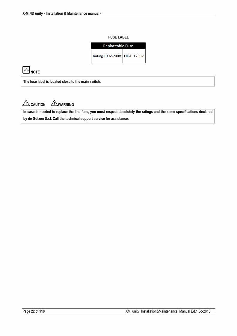
FUSE LABEL
NOTE
The fuse label is located close to the main switch.
CAUTION WARNING
In case is needed to replace the line fuse, you must respect absolutely the ratings and the same specifications declared
by de Götzen S.r.l. Call the technical support service for assistance.
� Installation & Maintenance manual � X�MIND unity
XM_unity_Installation&Maintenance_Manual Ed.1.3c2013 Page 23 of 110
3. INSTALLATION REQUIREMENTS
WARNING
$���������������������������������������+����� ������ ������������� &'$ �'�-%&� !��.�� ����������������������������(��������+� ���� ����������� ����������� ���������� ������� ���� ��������������� ���� ��/����������������+����������� ������������������������������������������������������������ ��� ����� ���������� ���������� ����� ���� ����� ��� ��� ����������� ����� ���� ������ ����� ���� ������������ ���������� �������������������������������������������������(�����������������������������������������
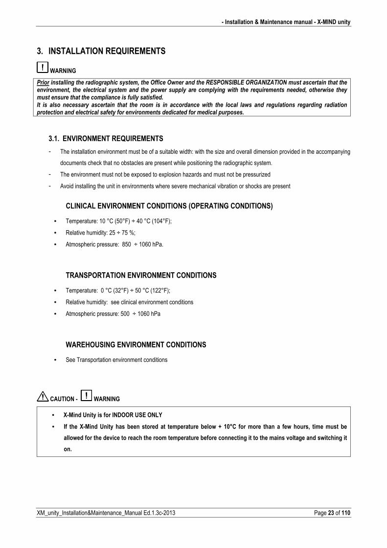
3.1. ENVIRONMENT REQUIREMENTS
� The installation environment must be of a suitable width: with the size and overall dimension provided in the accompanying
documents check that no obstacles are present while positioning the radiographic system.
� The environment must not be exposed to explosion hazards and must not be pressurized
� Avoid installing the unit in environments where severe mechanical vibration or shocks are present
CLINICAL ENVIRONMENT CONDITIONS (OPERATING CONDITIONS)
• Temperature: 10 °C (50°F) ÷ 40 °C (104°F);
• Relative humidity: 25 ÷ 75 %;
• Atmospheric pressure: 850 ÷ 1060 hPa.
TRANSPORTATION ENVIRONMENT CONDITIONS
• Temperature: 0 °C (32°F) ÷ 50 °C (122°F);
• Relative humidity: see clinical environment conditions
• Atmospheric pressure: 500 ÷ 1060 hPa
WAREHOUSING ENVIRONMENT CONDITIONS
• See Transportation environment conditions
CAUTION � WARNING
• X�Mind Unity is for INDOOR USE ONLY
• If the X�Mind Unity has been stored at temperature below + 10°C for more than a few hours, time must be
allowed for the device to reach the room temperature before connecting it to the mains voltage and switching it
on.
X�MIND unity � Installation & Maintenance manual �
Page 24 of 110 XM_unity_Installation&Maintenance_Manual Ed.1.3c2013
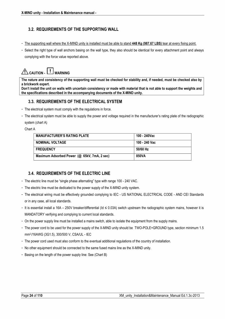
3.2. REQUIREMENTS OF THE SUPPORTING WALL
� The supporting wall where the XMIND unity is installed must be able to stand 448 Kg (987.67 LBS) tear at every fixing point.
� Select the right type of wall anchors basing on the wall type, they also should be identical for every attachment point and always
complying with the force value reported above.
CAUTION � WARNING
The nature and consistency of the supporting wall must be checked for stability and, if needed, must be checked also by a brickwork expert. Don’t install the unit on walls with uncertain consistency or made with material that is not able to support the weights and the specifications described in the accompanying documents of the X�MIND unity.
3.3. REQUIREMENTS OF THE ELECTRICAL SYSTEM
� The electrical system must comply with the regulations in force.
� The electrical system must be able to supply the power and voltage required in the manufacturer’s rating plate of the radiographic
system (chart A)
Chart A
MANUFACTURER’S RATING PLATE 100 � 240Vac
NOMINAL VOLTAGE 100 � 240 Vac
FREQUENCY 50/60 Hz
Maximum Adsorbed Power (@ 65kV, 7mA, 2 sec) 850VA
3.4. REQUIREMENTS OF THE ELECTRIC LINE
� The electric line must be “single phase alternating” type with range 100 240 VAC.
� The electric line must be dedicated to the power supply of the XMIND unity system.
� The electrical wiring must be effectively grounded complying to IEC US NATIONAL ELECTRICAL CODE AND CEI Standards
or in any case, all local standards.
� It is essential install a 16A – 250V breaker/differential (Id ≤ 0.03A) switch upstream the radiographic system mains, however it is
MANDATORY verifying and complying to current local standards.
� On the power supply line must be installed a mains switch, able to isolate the equipment from the supply mains.
� The power cord to be used for the power supply of the XMIND unity should be TWOPOLE+GROUND type, section minimum 1.5
mm2 /16AWG (3G1.5), 300/500 V, CSA/UL IEC
� The power cord used must also conform to the eventual additional regulations of the country of installation.
� No other equipment should be connected to the same fused mains line as the XMIND unity.
� Basing on the length of the power supply line: See (Chart B)
� Installation & Maintenance manual � X�MIND unity
XM_unity_Installation&Maintenance_Manual Ed.1.3c2013 Page 25 of 110
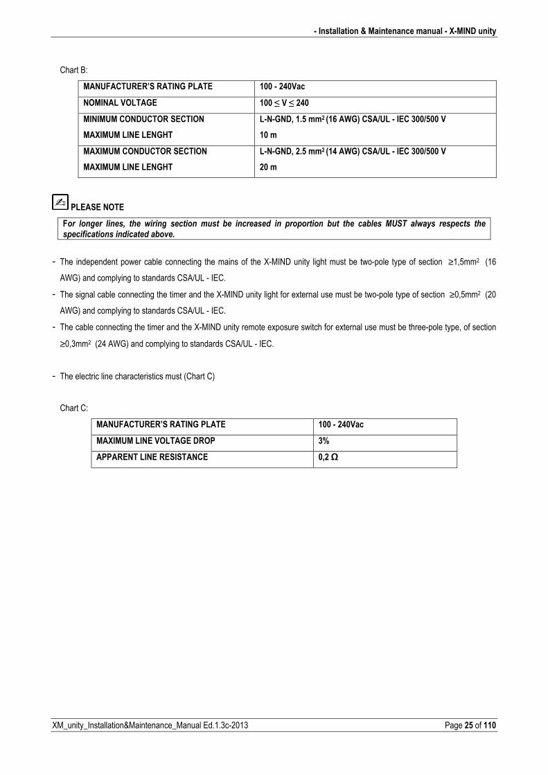
Chart B:
MANUFACTURER’S RATING PLATE 100 � 240Vac
NOMINAL VOLTAGE 100 ≤ V ≤ 240
MINIMUM CONDUCTOR SECTION
MAXIMUM LINE LENGHT
L�N�GND, 1.5 mm2 (16 AWG) CSA/UL � IEC 300/500 V
10 m
MAXIMUM CONDUCTOR SECTION
MAXIMUM LINE LENGHT
L�N�GND, 2.5 mm2 (14 AWG) CSA/UL � IEC 300/500 V
20 m
PLEASE NOTE
F��� ������� �����+� ���� ������� �������� ����� *�� ���������� ��� ����������� *��� ���� ��*���� 0�'�� ������� ��������� ������������������������������*�(��
� The independent power cable connecting the mains of the XMIND unity light must be twopole type of section ≥1,5mm2 (16
AWG) and complying to standards CSA/UL IEC.
� The signal cable connecting the timer and the XMIND unity light for external use must be twopole type of section ≥0,5mm2 (20
AWG) and complying to standards CSA/UL IEC.
� The cable connecting the timer and the XMIND unity remote exposure switch for external use must be threepole type, of section
≥0,3mm2 (24 AWG) and complying to standards CSA/UL IEC.
� The electric line characteristics must (Chart C)
Chart C:
MANUFACTURER’S RATING PLATE 100 � 240Vac
MAXIMUM LINE VOLTAGE DROP 3%
APPARENT LINE RESISTANCE 0,2 W
X�MIND unity � Installation & Maintenance manual �
Page 26 of 110 XM_unity_Installation&Maintenance_Manual Ed.1.3c2013
3.5. ELECTRICAL CONNECTIONS
WARNING
$������������������������������������������+���������(���*���������������������������������������*������������
The electrical system must be suitably earthed, in compliance with IEC and American NEC standards and with the laws in force in the country of installation.
In Italy, the system must be made in a workmanlike manner and in compliance with the CEI 648 standard, including all collateral
standards concerning premises dedicated for medical purposes
XRay control unit (Timer)
On the timer installation wall, suitable runs for the following electric cables must be provided, according to the installation electric
diagram:
� XRay control unit (Timer) mains cables
� Cables connecting the timer and the XRay signalling lamp X�MIND unity light (optional) (20 AWG, CSA/UL/IEC)
� Cables connecting the timer and the X�MIND unity remote control button (optional) (24 AWG, CSA/UL/IEC)
CAUTION
��������������������(������������+�����"#�����������������������*�����������������������������������������������������������
�����������������������������"��������������"�������������
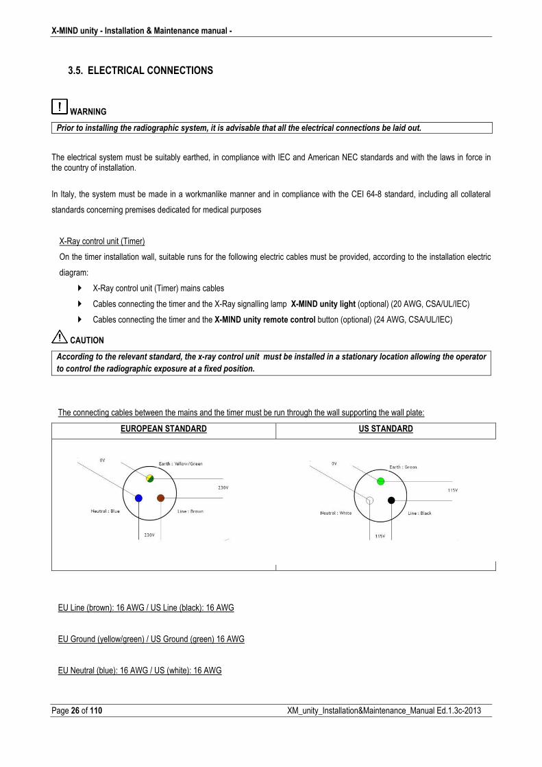
The connecting cables between the mains and the timer must be run through the wall supporting the wall plate:
EUROPEAN STANDARD US STANDARD
EU Line (brown): 16 AWG / US Line (black): 16 AWG
EU Ground (yellow/green) / US Ground (green) 16 AWG
EU Neutral (blue): 16 AWG / US (white): 16 AWG
� Installation & Maintenance manual � X�MIND unity
XM_unity_Installation&Maintenance_Manual Ed.1.3c2013 Page 27 of 110
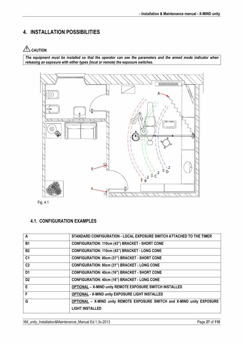
4. INSTALLATION POSSIBILITIES
CAUTION
���� �/�������� ����� *�� ���������� ��� ����� ���� ��������� ���� ���� ���� ����������� ���� ���� ������ ����� ���������� �������������������"�������������������������1���������������2������"�����������������
Fig. 4.1
4.1. CONFIGURATION EXAMPLES
A STANDARD CONFIGURATION � LOCAL EXPOSURE SWITCH ATTACHED TO THE TIMER
B1 CONFIGURATION: 110cm (43”) BRACKET � SHORT CONE
B2 CONFIGURATION: 110cm (43”) BRACKET � LONG CONE
C1 CONFIGURATION: 80cm (31”) BRACKET � SHORT CONE
C2 CONFIGURATION: 80cm (31”) BRACKET � LONG CONE
D1 CONFIGURATION: 40cm (16”) BRACKET � SHORT CONE
D2 CONFIGURATION: 40cm (16”) BRACKET � LONG CONE
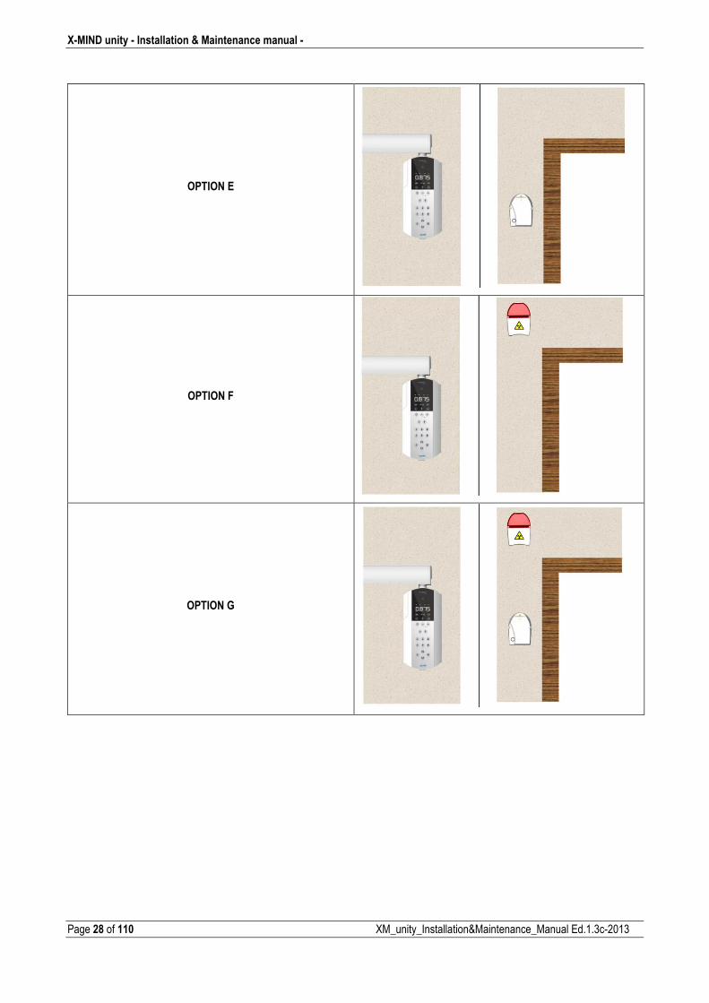
E OPTIONAL – X�MIND unity REMOTE EXPOSURE SWITCH INSTALLED
F OPTIONAL � X�MIND unity EXPOSURE LIGHT INSTALLED
G OPTIONAL – X�MIND unity REMOTE EXPOSURE SWITCH and X�MIND unity EXPOSURE
LIGHT INSTALLED
X�MIND unity � Installation & Maintenance manual �
Page 28 of 110 XM_unity_Installation&Maintenance_Manual Ed.1.3c2013
OPTION E
OPTION F
OPTION G
� Installation & Maintenance manual � X�MIND unity
XM_unity_Installation&Maintenance_Manual Ed.1.3c2013 Page 29 of 110
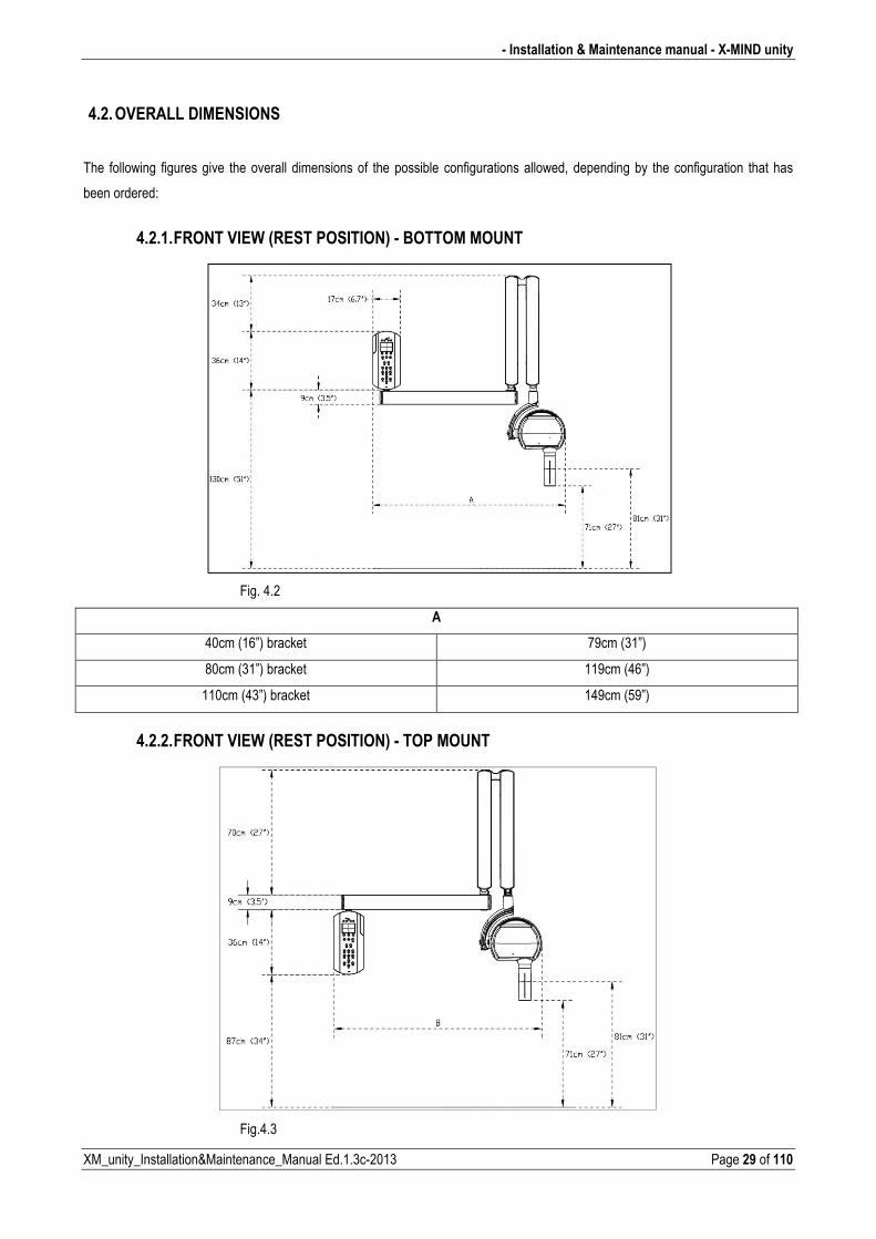
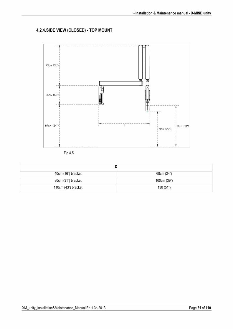
4.2. OVERALL DIMENSIONS
The following figures give the overall dimensions of the possible configurations allowed, depending by the configuration that has
been ordered:
4.2.1. FRONT VIEW (REST POSITION) � BOTTOM MOUNT
Fig. 4.2
A
40cm (16”) bracket 79cm (31”)
80cm (31”) bracket 119cm (46”)
110cm (43”) bracket 149cm (59”)
4.2.2. FRONT VIEW (REST POSITION) � TOP MOUNT
Fig.4.3
X�MIND unity � Installation & Maintenance manual �
Page 30 of 110 XM_unity_Installation&Maintenance_Manual Ed.1.3c2013
B
40cm (16”) bracket 79cm (31”)
80cm (31”) bracket 119cm (46”)
110cm (43”) bracket 149cm (59”)
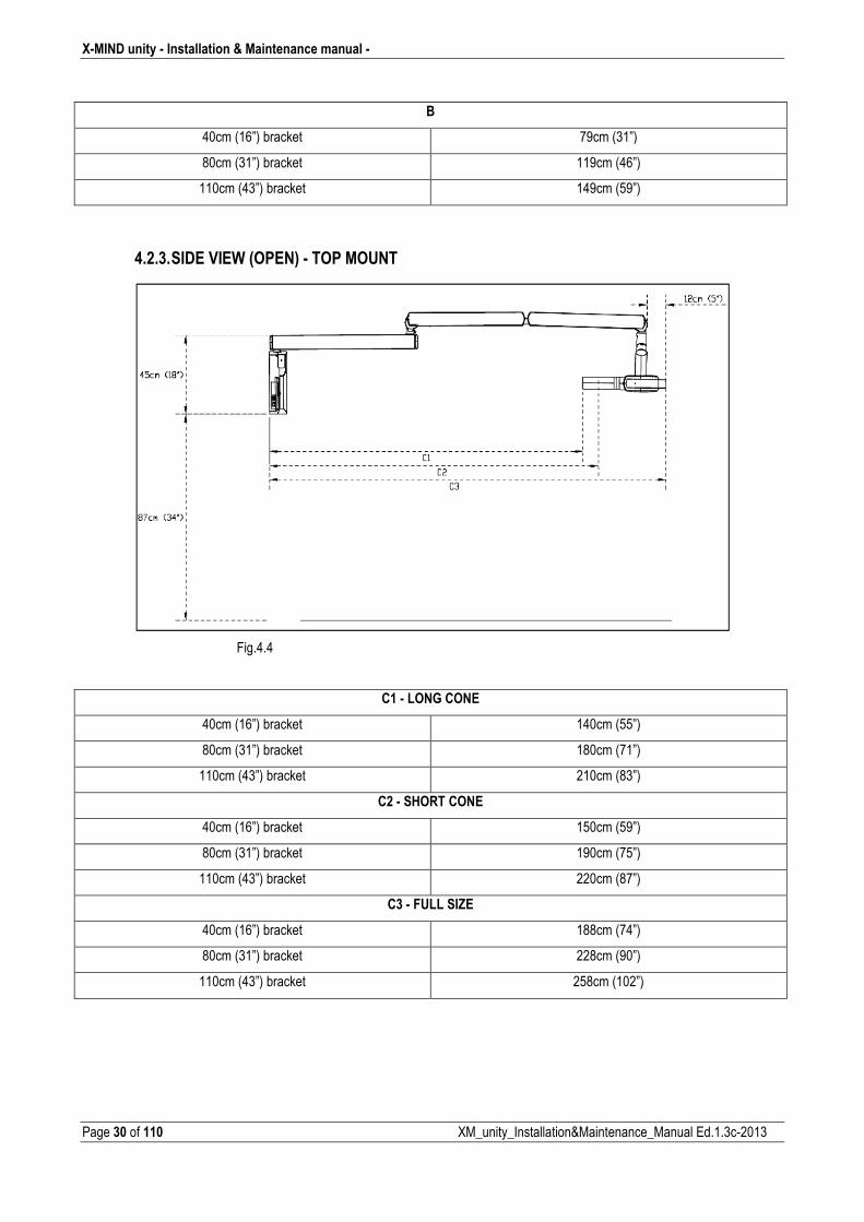
4.2.3. SIDE VIEW (OPEN) � TOP MOUNT
Fig.4.4
C1 � LONG CONE
40cm (16”) bracket 140cm (55”)
80cm (31”) bracket 180cm (71”)
110cm (43”) bracket 210cm (83”)
C2 � SHORT CONE
40cm (16”) bracket 150cm (59”)
80cm (31”) bracket 190cm (75”)
110cm (43”) bracket 220cm (87”)
C3 � FULL SIZE
40cm (16”) bracket 188cm (74”)
80cm (31”) bracket 228cm (90”)
110cm (43”) bracket 258cm (102”)
� Installation & Maintenance manual � X�MIND unity
XM_unity_Installation&Maintenance_Manual Ed.1.3c2013 Page 31 of 110
4.2.4. SIDE VIEW (CLOSED) � TOP MOUNT
Fig.4.5
D
40cm (16”) bracket 60cm (24”)
80cm (31”) bracket 100cm (39”)
110cm (43”) bracket 130 (51”)
X�MIND unity � Installation & Maintenance manual �
Page 32 of 110 XM_unity_Installation&Maintenance_Manual Ed.1.3c2013
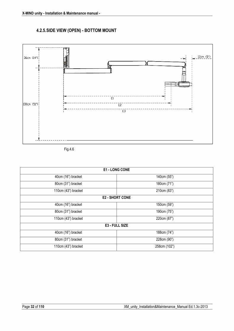
4.2.5. SIDE VIEW (OPEN) � BOTTOM MOUNT
Fig.4.6
E1 � LONG CONE
40cm (16”) bracket 140cm (55”)
80cm (31”) bracket 180cm (71”)
110cm (43”) bracket 210cm (83”)
E2 � SHORT CONE
40cm (16”) bracket 150cm (59”)
80cm (31”) bracket 190cm (75”)
110cm (43”) bracket 220cm (87”)
E3 � FULL SIZE
40cm (16”) bracket 188cm (74”)
80cm (31”) bracket 228cm (90”)
110cm (43”) bracket 258cm (102”)
� Installation & Maintenance manual � X�MIND unity
XM_unity_Installation&Maintenance_Manual Ed.1.3c2013 Page 33 of 110
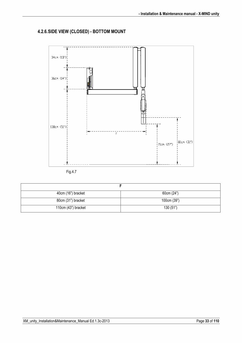
4.2.6. SIDE VIEW (CLOSED) � BOTTOM MOUNT
Fig.4.7
F
40cm (16”) bracket 60cm (24”)
80cm (31”) bracket 100cm (39”)
110cm (43”) bracket 130 (51”)
X�MIND unity � Installation & Maintenance manual �
Page 34 of 110 XM_unity_Installation&Maintenance_Manual Ed.1.3c2013
5. INSTALLATION
CAUTION
The X�MIND unity radiographic system must be installed by professionally trained technicians, who must be able to
certify their work to their local state regulatory body.
WARNING
Prior to installing the radiographic system verify that all needed requirements have been met (refer to Chapter “Installation Specifications”)
CAUTION � WARNING
During the installation pay extreme attention of the proper connection of the all internal grounding leads of the X�MIND
unity, that must be properly and safely connected. For additional information refer to the electrical and wiring schemes
provided in the Installation & Maintenance Manual.
It is mandatory check the safety ground continuity with proper calibrated instruments and according to the regulations
in force after the installation, before the first use of the unit or after each maintenance or repairing.
The checking of the proper electrical connections and safety grounding must be part of the periodical maintenance of
the X�MIND unity device.
� Installation & Maintenance manual � X�MIND unity
XM_unity_Installation&Maintenance_Manual Ed.1.3c2013 Page 35 of 110
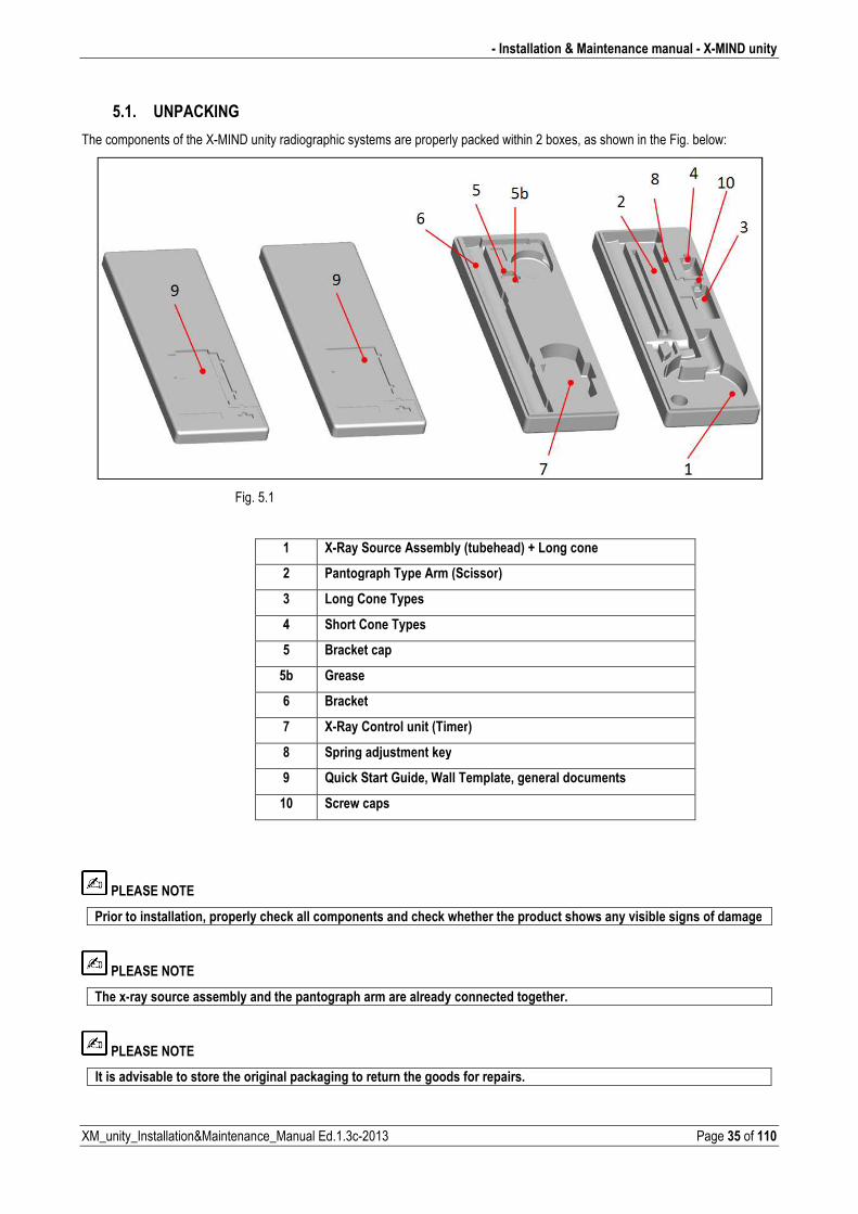
5.1. UNPACKING
The components of the XMIND unity radiographic systems are properly packed within 2 boxes, as shown in the Fig. below:
Fig. 5.1
1 X�Ray Source Assembly (tubehead) + Long cone
2 Pantograph Type Arm (Scissor)
3 Long Cone Types
4 Short Cone Types
5 Bracket cap
5b Grease
6 Bracket
7 X�Ray Control unit (Timer)
8 Spring adjustment key
9 Quick Start Guide, Wall Template, general documents
10 Screw caps
PLEASE NOTE
Prior to installation, properly check all components and check whether the product shows any visible signs of damage
PLEASE NOTE
The x�ray source assembly and the pantograph arm are already connected together.
PLEASE NOTE
It is advisable to store the original packaging to return the goods for repairs.
X�MIND unity � Installation & Maintenance manual �
Page 36 of 110 XM_unity_Installation&Maintenance_Manual Ed.1.3c2013
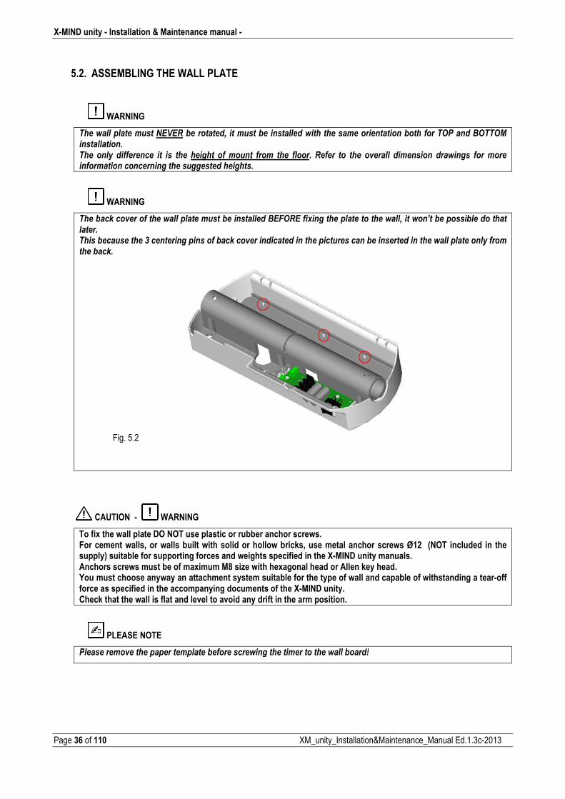
5.2. ASSEMBLING THE WALL PLATE
WARNING
���������������������&3& �*���������+���������*��������������������������������������*��������� $�����- �� 0������������������� ����� ����������� ��� ��� ���� ������� ��������� ����� ���� ������� ����� ��� ���� �(������ ���������� ��������� ������������������������������������������������������
WARNING
����*��)���(��������������������������*������������-&4 &���"�������������������������+����������*�������*�����������������������*�����������5�������������������*��)���(���������������������������������*��������������������������������������������*��)���
�Fig. 5.2
�
CAUTION � WARNING
To fix the wall plate DO NOT use plastic or rubber anchor screws. For cement walls, or walls built with solid or hollow bricks, use metal anchor screws Ø12 (NOT included in the supply) suitable for supporting forces and weights specified in the X�MIND unity manuals. Anchors screws must be of maximum M8 size with hexagonal head or Allen key head. You must choose anyway an attachment system suitable for the type of wall and capable of withstanding a tear�off force as specified in the accompanying documents of the X�MIND unity. Check that the wall is flat and level to avoid any drift in the arm position.
PLEASE NOTE
$����������(���������������������*�������������������������������������*����6�
� Installation & Maintenance manual � X�MIND unity
XM_unity_Installation&Maintenance_Manual Ed.1.3c2013 Page 37 of 110
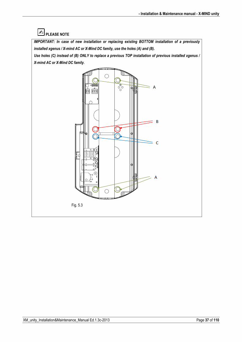
PLEASE NOTE
�0$ ���7� ��� ����� ��� ���� ������������� ��� ���������� �"������� - �� 0� ������������� ��� �� ���(�������
����������"������8�9#���������9#0����,�������+���������������12�����1-2��
����������12������������1-2� �%:�����������������(������ $��������������������(���������������"������8�
9#���������9#0����,���������
Fig. 5.3
�
X�MIND unity � Installation & Maintenance manual �
Page 38 of 110 XM_unity_Installation&Maintenance_Manual Ed.1.3c2013
PLEASE NOTE
�0$ ���7��������������������������(��������������������������������������������������������*���)������+�
���������������*�������*���)���������������������*��������"�����������������
�
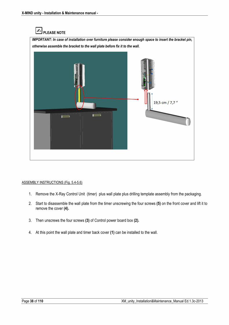
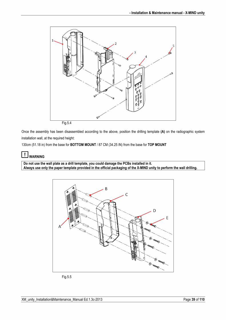
ASSEMBLY INSTRUCTIONS (Fig. 5.45.6)
1. Remove the XRay Control Unit (timer) plus wall plate plus drilling template assembly from the packaging.
2. Start to disassemble the wall plate from the timer unscrewing the four screws (5) on the front cover and lift it to
remove the cover (4).
3. Then unscrews the four screws (3) of Control power board box (2).
4. At this point the wall plate and timer back cover (1) can be installed to the wall.
� Installation & Maintenance manual � X�MIND unity
XM_unity_Installation&Maintenance_Manual Ed.1.3c2013 Page 39 of 110
Fig.5.4
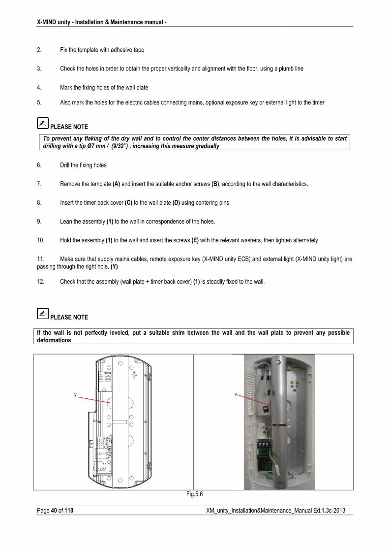
Once the assembly has been disassembled according to the above, position the drilling template (A) on the radiographic system
installation wall, at the required height:
130cm (51.18 in) from the base for BOTTOM MOUNT / 87 CM (34.25 IN) from the base for TOP MOUNT
WARNING
Do not use the wall plate as a drill template, you could damage the PCBs installed in it. Always use only the paper template provided in the official packaging of the X�MIND unity to perform the wall drilling.
Fig.5.5
X�MIND unity � Installation & Maintenance
Page 40 of 110
2. Fix the template with adhesive tape
3. Check the holes in order to obtain
4. Mark the fixing holes of the wall pla 5. Also mark the holes for the electric
PLEASE NOTE
������(�������� ���)������� ���������������������������������;<����8��1=85>?2�+�����
6. Drill the fixing holes
7. Remove the template (A) and inser
8. Insert the timer back cover (C) to th
9. Lean the assembly (1) to the wall in
10. Hold the assembly (1) to the wall a
11. Make sure that supply mains cablepassing through the right hole. (Y) 12. Check that the assembly (wall plate
PLEASE NOTE
If the wall is not perfectly leveled, put deformations
ce manual �
XM_unity_Installation&Maintena
ape
the proper verticality and alignment with the floor, using a pl
plate
tric cables connecting mains, optional exposure key or externa
�������� ����������� ���������������������*������� �����������������������������������������
sert the suitable anchor screws (B), according to the wall char
o the wall plate (D) using centering pins.
ll in correspondence of the holes.
ll and insert the screws (E) with the relevant washers, then tigh
bles, remote exposure key (XMIND unity ECB) and external
late + timer back cover) (1) is steadily fixed to the wall.
ut a suitable shim between the wall and the wall plate
Fig.5.6
nance_Manual Ed.1.3c2013
plumb line
rnal light to the timer
����+� ��� �����(���*��� ���������
haracteristics.
tighten alternately.
nal light (XMIND unity light) are
ate to prevent any possible
� Installation & Maintenance manual � X�MIND unity
XM_unity_Installation&Maintenance_Manual Ed.1.3c2013 Page 41 of 110
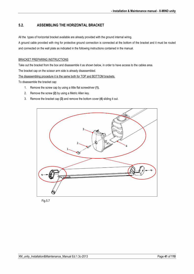
5.2. ASSEMBLING THE HORIZONTAL BRACKET
All the types of horizontal bracket available are already provided with the ground internal wiring.
A ground cable provided with ring for protective ground connection is connected at the bottom of the bracket and it must be routed
and connected on the wall plate as indicated in the following instructions contained in the manual.
BRACKET PREPARING INSTRUCTIONS
Take out the bracket from the box and disassemble it as shown below, in order to have access to the cables area.
The bracket cap on the scissor arm side is already disassembled.
The disassembling procedure it is the same both for TOP and BOTTOM brackets.
To disassemble the bracket cap:
1. Remove the screw cap by using a little flat screwdriver (1).
2. Remove the screw (2) by using a Metric Allen key.
3. Remove the bracket cap (3) and remove the bottom cover (4) sliding it out.
Fig.5.7
X�MIND unity � Installation & Maintenance manual �
Page 42 of 110 XM_unity_Installation&Maintenance_Manual Ed.1.3c2013
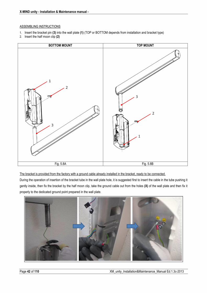
ASSEMBLING INSTRUCTIONS
1. Insert the bracket pin (3) into the wall plate (1) (TOP or BOTTOM depends from installation and bracket type) 2. Insert the half moon clip (2)
BOTTOM MOUNT TOP MOUNT
Fig. 5.8A Fig. 5.8B
The bracket is provided from the factory with a ground cable already installed in the bracket, ready to be connected.
During the operation of insertion of the bracket tube in the wall plate hole, it is suggested first to insert the cable in the tube pushing it
gently inside, then fix the bracket by the half moon clip, take the ground cable out from the holes (X) of the wall plate and then fix it
properly to the dedicated ground point prepared in the wall plate.
� Installation & Maintenance manual � X�MIND unity
XM_unity_Installation&Maintenance_Manual Ed.1.3c2013 Page 43 of 110
Fig. 5.9
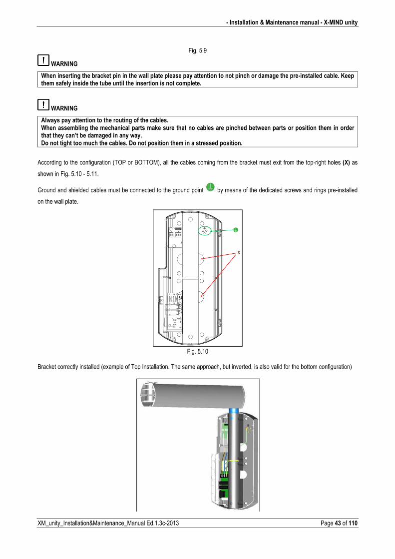
WARNING
When inserting the bracket pin in the wall plate please pay attention to not pinch or damage the pre�installed cable. Keep them safely inside the tube until the insertion is not complete.
WARNING
Always pay attention to the routing of the cables. When assembling the mechanical parts make sure that no cables are pinched between parts or position them in order that they can’t be damaged in any way. Do not tight too much the cables. Do not position them in a stressed position.�
According to the configuration (TOP or BOTTOM), all the cables coming from the bracket must exit from the topright holes (X) as
shown in Fig. 5.10 5.11.
Ground and shielded cables must be connected to the ground point by means of the dedicated screws and rings preinstalled
on the wall plate.
Fig. 5.10
Bracket correctly installed (example of Top Installation. The same approach, but inverted, is also valid for the bottom configuration)
X�MIND unity � Installation & Maintenance manual �
Page 44 of 110 XM_unity_Installation&Maintenance_Manual Ed.1.3c2013
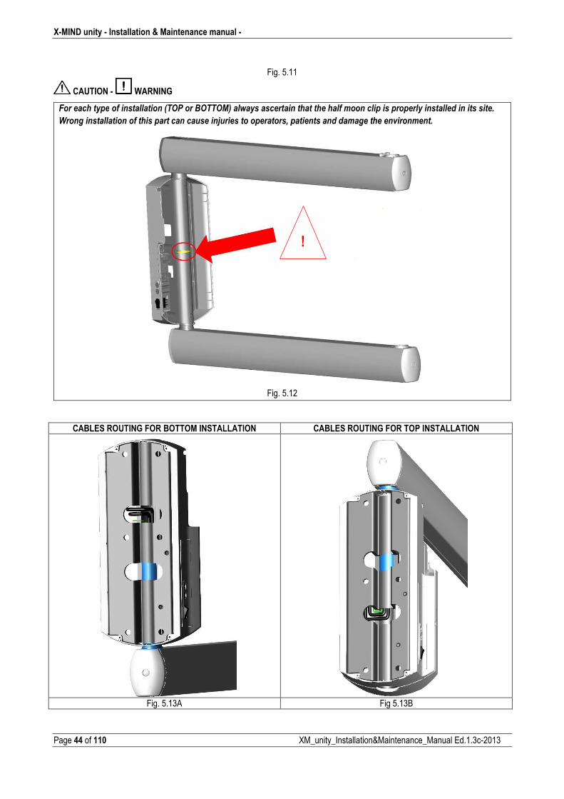
Fig. 5.11
CAUTION � WARNING
4�����������������������������1� $����- �� 02�����������������������������������������������������������������������������
���������������������������������������������������������������+���������������������������(����������
Fig. 5.12�
CABLES ROUTING FOR BOTTOM INSTALLATION CABLES ROUTING FOR TOP INSTALLATION
Fig. 5.13A Fig 5.13B
!
� Installation & Maintenance manual � X�MIND unity
XM_unity_Installation&Maintenance_Manual Ed.1.3c2013 Page 45 of 110
PLEASE NOTE
Prevent all foreign matter (dirt, dust, cement, etc.) from setting on the pin seat.
The pin must slide freely in its seat. If required, thoroughly clean and lubricate with Molikote D grease type ONLY as
specified by de Götzen S.r.l. – Acteon Group. Don’t try to use other type of grease.
PLEASE NOTE
Check accurately with a spirit level instrument, the exact alignment between the bracket and the ground floor.
CAUTION � WARNING
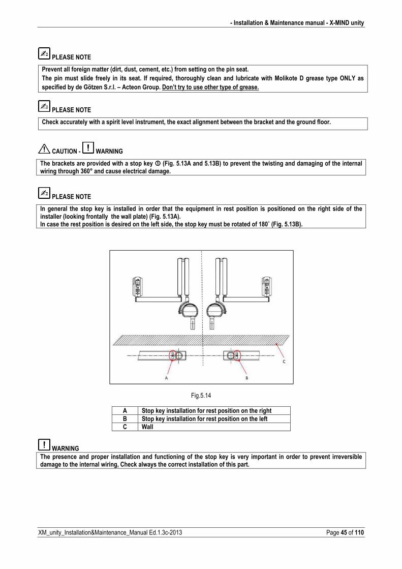
The brackets are provided with a stop key ���� (Fig. 5.13A and 5.13B) to prevent the twisting and damaging of the internal wiring through 360° and cause electrical damage.
PLEASE NOTE
In general the stop key is installed in order that the equipment in rest position is positioned on the right side of the installer (looking frontally the wall plate) (Fig. 5.13A). In case the rest position is desired on the left side, the stop key must be rotated of 180˚ (Fig. 5.13B). �
�
�
��
Fig.5.14 �
A Stop key installation for rest position on the right
B Stop key installation for rest position on the left C Wall
WARNING
The presence and proper installation and functioning of the stop key is very important in order to prevent irreversible damage to the internal wiring, Check always the correct installation of this part.
�
X�MIND unity � Installation & Maintenance manual �
Page 46 of 110 XM_unity_Installation&Maintenance_Manual Ed.1.3c2013
5.3. ASSEMBLING THE SCISSOR ARM
The scissor arm is provided with the XRay source assembly (tubehead) already connected and installed.
CAUTION
The spring contained in the portion of the arm relevant to the tubehead side (Arm B) is provided unloaded from the factory for safety reasons. Anyway, when removing the assembly pantograph arm and tubehead from the package, check that the mechanical tension is fully unloaded.�
CAUTION
Pay attention when managing the assembly pantograph arm plus tubehead. This assembly is quite heavy and is an extremely delicate part. Pay attention moving this assembly, we suggest to move that as shown below to be more comfortable during assembling operations.
CAUTION
Risk of injury! Do not fold up or try to fold up the scissor arm in the uninstalled state! Carefully transport the scissor arm ONLY in the unfolded state.
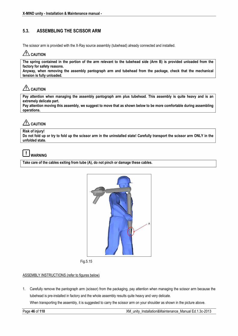
WARNING
Take care of the cables exiting from tube (A), do not pinch or damage these cables.
Fig.5.15
ASSEMBLY INSTRUCTIONS (refer to figures below)
1. Carefully remove the pantograph arm (scissor) from the packaging, pay attention when managing the scissor arm because the
tubehead is preinstalled in factory and the whole assembly results quite heavy and very delicate.
When transporting the assembly, it is suggested to carry the scissor arm on your shoulder as shown in the picture above.
� Installation & Maintenance manual � X�MIND unity
XM_unity_Installation&Maintenance_Manual Ed.1.3c2013 Page 47 of 110
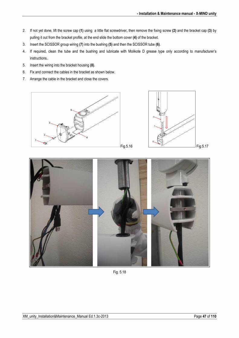
2. If not yet done, lift the screw cap (1) using a little flat screwdriver, then remove the fixing screw (2) and the bracket cap (3) by
pulling it out from the bracket profile, at the end slide the bottom cover (4) of the bracket.
3. Insert the SCISSOR group wiring (7) into the bushing (5) and then the SCISSOR tube (6).
4. If required, clean the tube and the bushing and lubricate with Molikote D grease type only according to manufacturer’s
instructions..
5. Insert the wiring into the bracket housing (8).
6. Fix and connect the cables in the bracket as shown below.
7. Arrange the cable in the bracket and close the covers.
Fig.5.16 Fig.5.17
Fig. 5.18
X�MIND unity � Installation & Maintenance manual �
Page 48 of 110 XM_unity_Installation&Maintenance_Manual Ed.1.3c2013
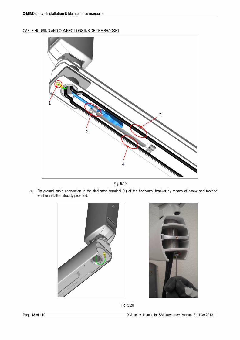
CABLE HOUSING AND CONNECTIONS INSIDE THE BRACKET
Fig. 5.19
1. Fix ground cable connection in the dedicated terminal (1) of the horizontal bracket by means of screw and toothed washer installed already provided.
Fig. 5.20
� Installation & Maintenance manual � X�MIND unity
XM_unity_Installation&Maintenance_Manual Ed.1.3c2013 Page 49 of 110
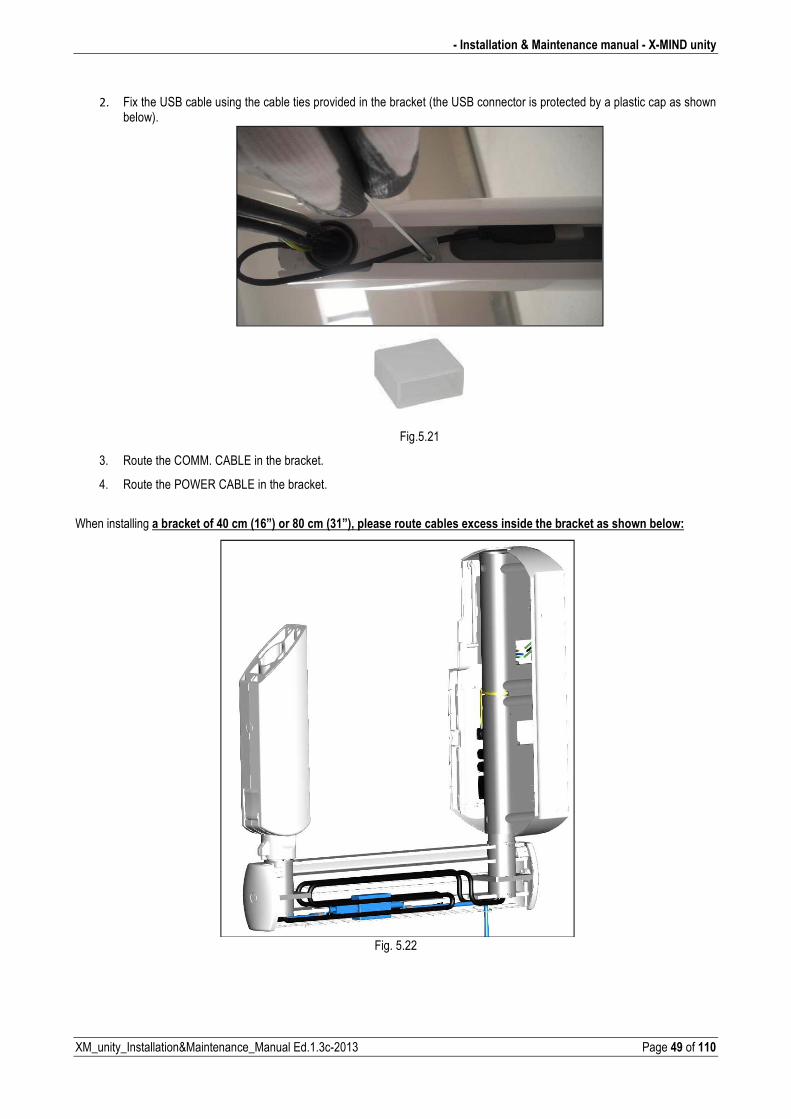
2. Fix the USB cable using the cable ties provided in the bracket (the USB connector is protected by a plastic cap as shown below).
Fig.5.21
3. Route the COMM. CABLE in the bracket.
4. Route the POWER CABLE in the bracket.
When installing a bracket of 40 cm (16”) or 80 cm (31”), please route cables excess inside the bracket as shown below:
Fig. 5.22
X�MIND unity � Installation & Maintenance manual �
Page 50 of 110 XM_unity_Installation&Maintenance_Manual Ed.1.3c2013
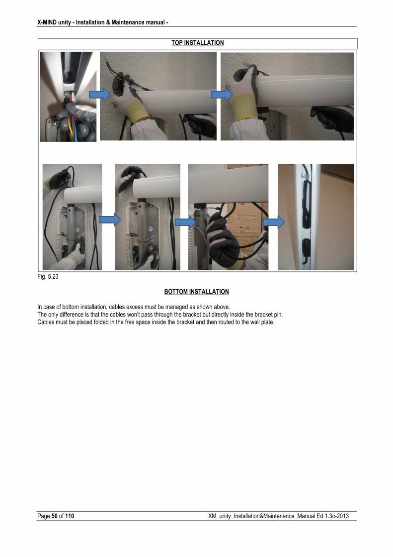
Fig. 5.23
BOTTOM INSTALLATION In case of bottom installation, cables excess must be managed as shown above. The only difference is that the cables won’t pass through the bracket but directly inside the bracket pin. Cables must be placed folded in the free space inside the bracket and then routed to the wall plate.
TOP INSTALLATION
� Installation & Maintenance manual � X�MIND unity
XM_unity_Installation&Maintenance_Manual Ed.1.3c2013 Page 51 of 110
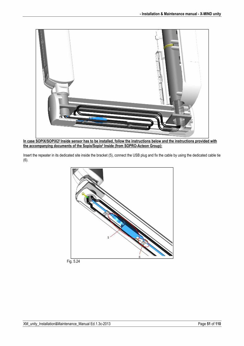
In case SOPIX/SOPIX22 Inside sensor has to be installed, follow the instructions below and the instructions provided with the accompanying documents of the Sopix/Sopix2 Inside (from SOPRO�Acteon Group): Insert the repeater in its dedicated site inside the bracket (5), connect the USB plug and fix the cable by using the dedicated cable tie (6).
Fig. 5.24
X�MIND unity � Installation & Maintenance manual �
Page 52 of 110 XM_unity_Installation&Maintenance_Manual Ed.1.3c2013
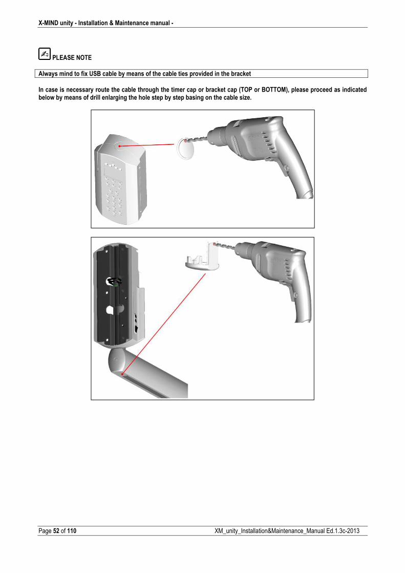
PLEASE NOTE
Always mind to fix USB cable by means of the cable ties provided in the bracket
In case is necessary route the cable through the timer cap or bracket cap (TOP or BOTTOM), please proceed as indicated below by means of drill enlarging the hole step by step basing on the cable size.
� Installation & Maintenance manual � X�MIND unity
XM_unity_Installation&Maintenance_Manual Ed.1.3c2013 Page 53 of 110
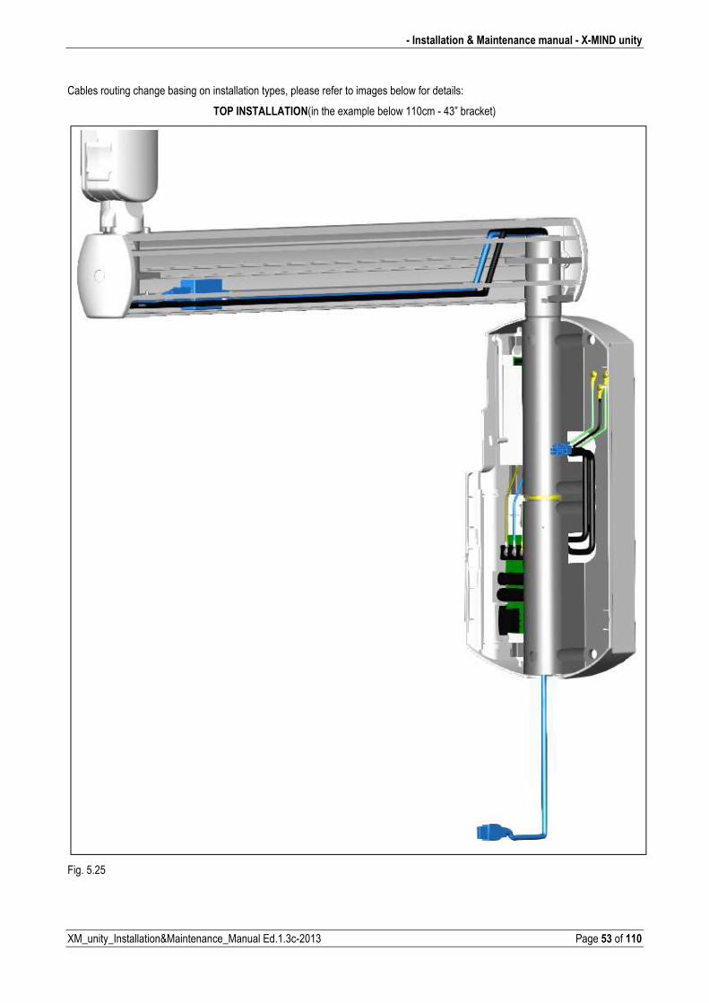
Cables routing change basing on installation types, please refer to images below for details:
TOP INSTALLATION(in the example below 110cm 43” bracket)
Fig. 5.25
X�MIND unity � Installation & Maintenance manual �
Page 54 of 110 XM_unity_Installation&Maintenance_Manual Ed.1.3c2013
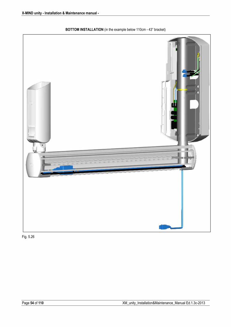
BOTTOM INSTALLATION (in the example below 110cm 43” bracket)
Fig. 5.26
� Installation & Maintenance manual � X�MIND unity
XM_unity_Installation&Maintenance_Manual Ed.1.3c2013 Page 55 of 110
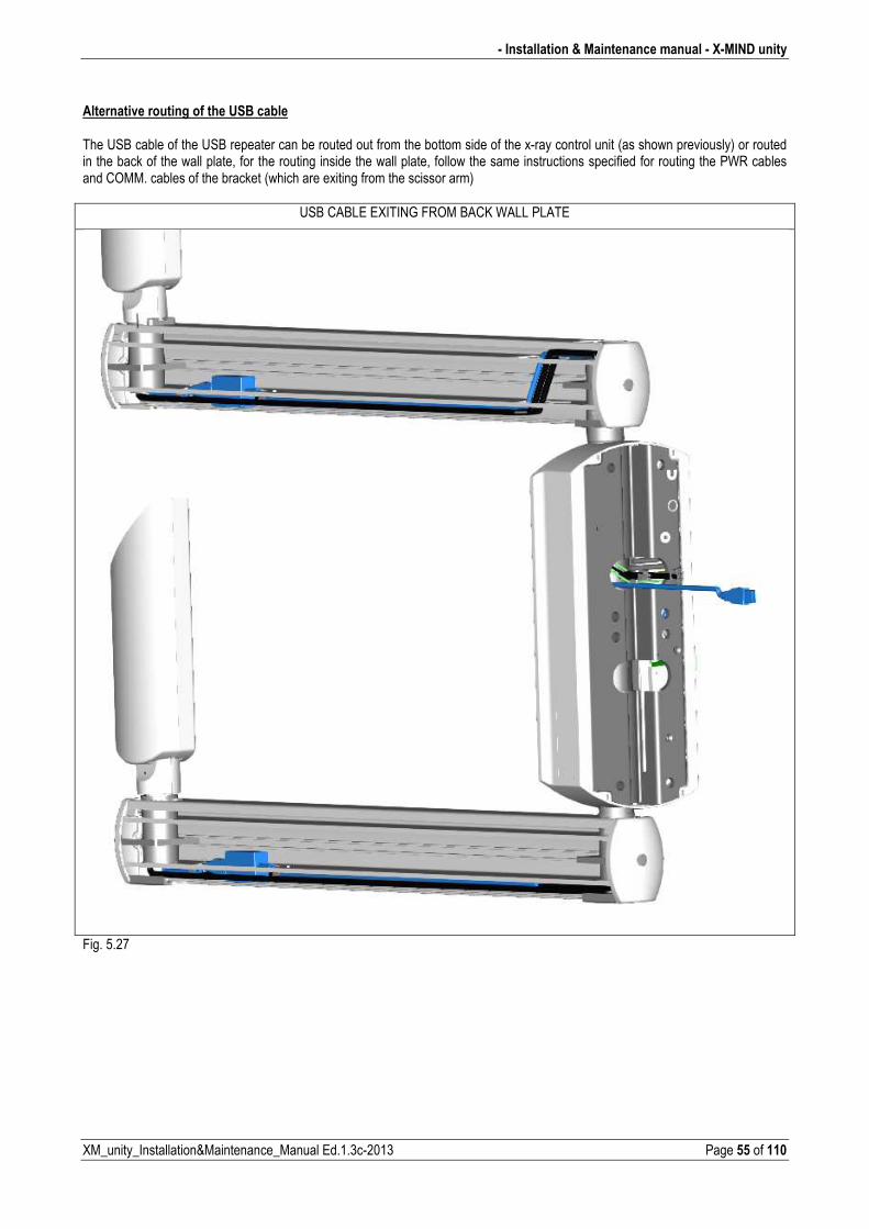
Alternative routing of the USB cable The USB cable of the USB repeater can be routed out from the bottom side of the xray control unit (as shown previously) or routed in the back of the wall plate, for the routing inside the wall plate, follow the same instructions specified for routing the PWR cables and COMM. cables of the bracket (which are exiting from the scissor arm)
USB CABLE EXITING FROM BACK WALL PLATE
Fig. 5.27
X�MIND unity � Installation & Maintenance manual �
Page 56 of 110 XM_unity_Installation&Maintenance_Manual Ed.1.3c2013
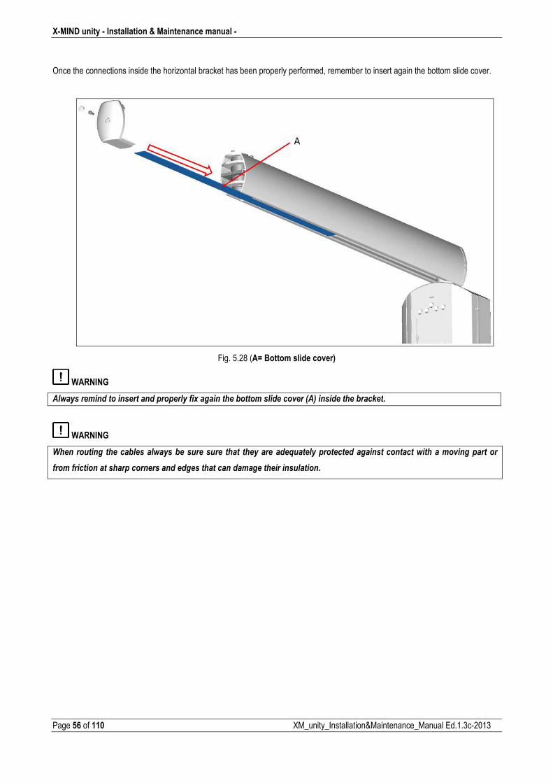
Once the connections inside the horizontal bracket has been properly performed, remember to insert again the bottom slide cover.
Fig. 5.28 (A= Bottom slide cover)
WARNING
��������������������������������������"�����������*��������������(���12������������*���)���
WARNING
������������� ������*�����������*������������ ����� ������������/������������������������������������������(������������
���������������������������������������������������������������������������
� Installation & Maintenance manual � X�MIND unity
XM_unity_Installation&Maintenance_Manual Ed.1.3c2013 Page 57 of 110
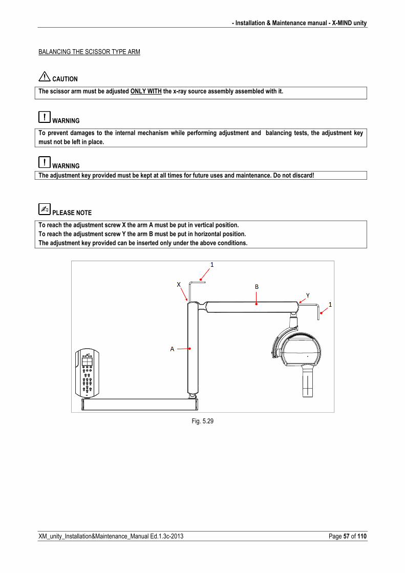
BALANCING THE SCISSOR TYPE ARM
CAUTION
The scissor arm must be adjusted ONLY WITH the x�ray source assembly assembled with it.
WARNING
To prevent damages to the internal mechanism while performing adjustment and balancing tests, the adjustment key
must not be left in place.
WARNING The adjustment key provided must be kept at all times for future uses and maintenance. Do not discard!
PLEASE NOTE
To reach the adjustment screw X the arm A must be put in vertical position.
To reach the adjustment screw Y the arm B must be put in horizontal position.
The adjustment key provided can be inserted only under the above conditions.
Fig. 5.29
X�MIND unity � Installation & Maintenance manual �
Page 58 of 110 XM_unity_Installation&Maintenance_Manual Ed.1.3c2013
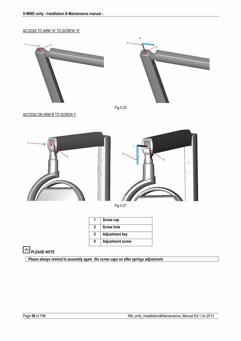
ACCESS TO ARM “A” TO SCREW “X”
Fig.5.30
ACCESS ON ARM B TO SCREW Y
Fig 5.31
1 Screw cap
2 Screw hole
3 Adjustment key
4 Adjustment screw
PLEASE NOTE
$����������������������������*������������������������������������������������������
� Installation & Maintenance manual � X�MIND unity
XM_unity_Installation&Maintenance_Manual Ed.1.3c2013 Page 59 of 110
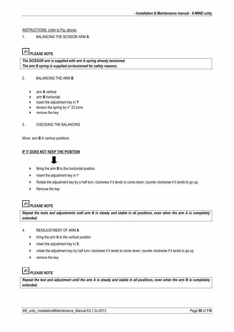
INSTRUCTIONS (refer to Fig. above)
1. BALANCING THE SCISSOR ARM A
PLEASE NOTE
����'�'' �����������������������������������������������������
��������-����������������������#�����������������������������
2. BALANCING THE ARM B
� arm A vertical � arm B horizontal � insert the adjustment key in Y � tension the spring by n° 22 turns � remove the key
3. CHECKING THE BALANCING
Move arm B in various positions
IF IT DOES NOT KEEP THE POSITION
� Bring the arm B to the horizontal position
� Insert the adjustment key in Y
� Rotate the adjustment key by a half turn: clockwise if it tends to come down; counter clockwise if it tends to go up;
� Remove the key
PLEASE NOTE
������ ���� ��������������������������������-� �����������������*��� ����������������+��(�������� ��������� ��������������
�"��������
4. READJUSTMENT OF ARM A
� bring the arm A to the vertical position
� insert the adjustment key in X
� rotate the adjustment key by half turn: clockwise if it tends to come down; counter clockwise if it tends to go up
� remove the key
PLEASE NOTE
��������������������������������������������������������������*�������������������+��(����������������-���������������
�"��������
X�MIND unity � Installation & Maintenance manual �
Page 60 of 110 XM_unity_Installation&Maintenance_Manual Ed.1.3c2013
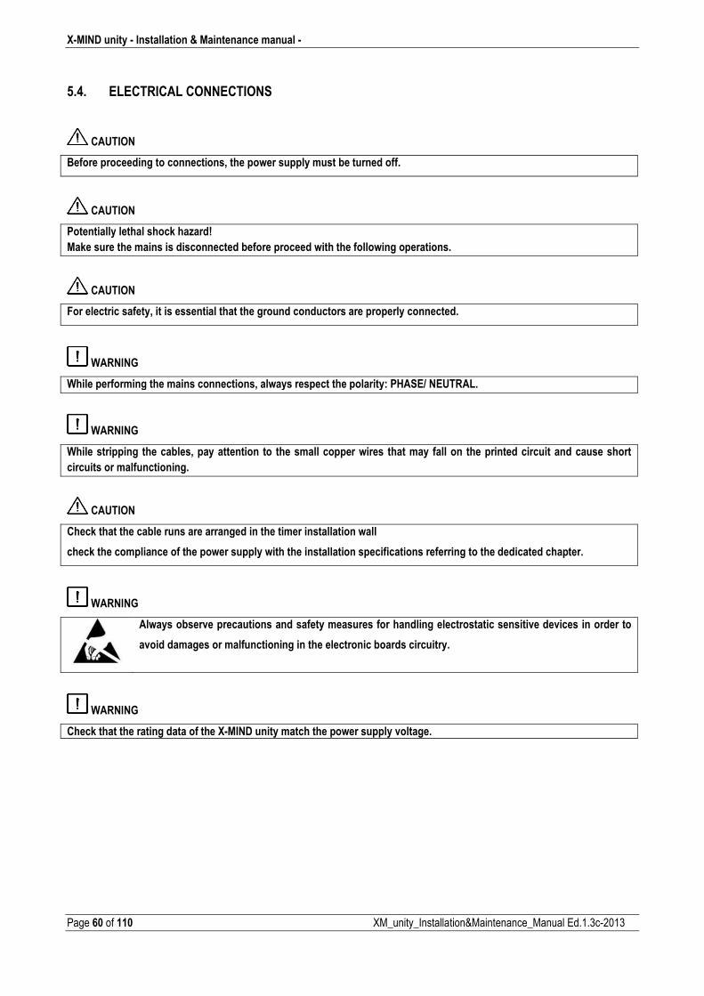
5.4. ELECTRICAL CONNECTIONS
CAUTION
Before proceeding to connections, the power supply must be turned off.
CAUTION
Potentially lethal shock hazard!
Make sure the mains is disconnected before proceed with the following operations.
CAUTION
For electric safety, it is essential that the ground conductors are properly connected.
WARNING
While performing the mains connections, always respect the polarity: PHASE/ NEUTRAL.
WARNING
While stripping the cables, pay attention to the small copper wires that may fall on the printed circuit and cause short
circuits or malfunctioning.
CAUTION
Check that the cable runs are arranged in the timer installation wall
check the compliance of the power supply with the installation specifications referring to the dedicated chapter.
WARNING
Always observe precautions and safety measures for handling electrostatic sensitive devices in order to
avoid damages or malfunctioning in the electronic boards circuitry.
WARNING
Check that the rating data of the X�MIND unity match the power supply voltage.
� Installation & Maintenance manual � X�MIND unity
XM_unity_Installation&Maintenance_Manual Ed.1.3c2013 Page 61 of 110
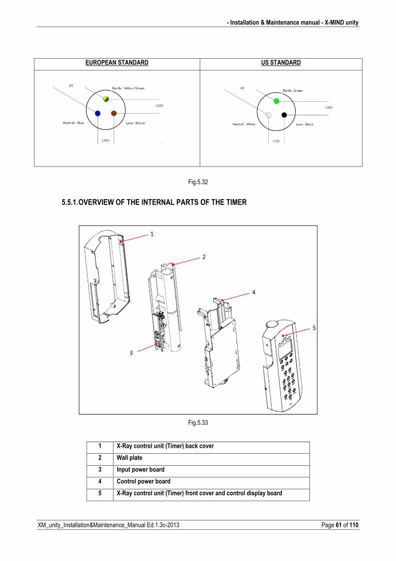
EUROPEAN STANDARD US STANDARD
Fig.5.32
5.5.1. OVERVIEW OF THE INTERNAL PARTS OF THE TIMER
Fig.5.33
1 X�Ray control unit (Timer) back cover
2 Wall plate
3 Input power board
4 Control power board
5 X�Ray control unit (Timer) front cover and control display board
X�MIND unity � Installation & Maintenance manual �
Page 62 of 110 XM_unity_Installation&Maintenance_Manual Ed.1.3c2013
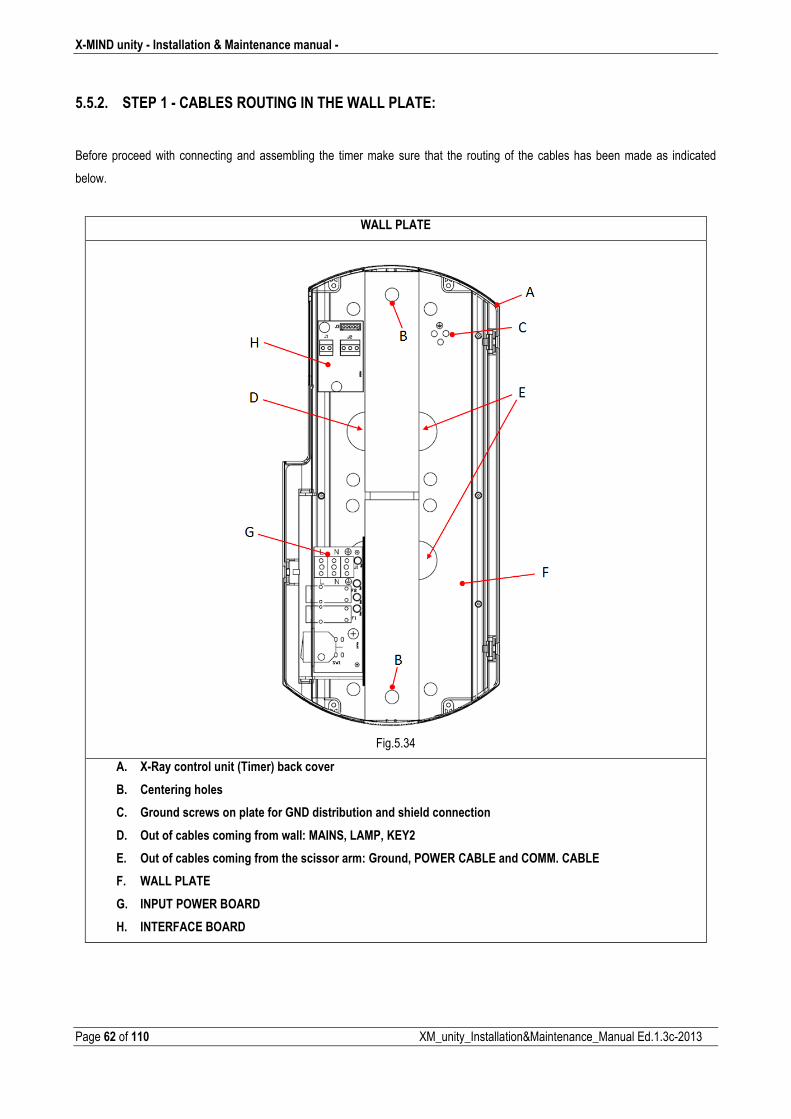
5.5.2. STEP 1 � CABLES ROUTING IN THE WALL PLATE:
Before proceed with connecting and assembling the timer make sure that the routing of the cables has been made as indicated
below.
WALL PLATE
Fig.5.34
A. X�Ray control unit (Timer) back cover
B. Centering holes
C. Ground screws on plate for GND distribution and shield connection
D. Out of cables coming from wall: MAINS, LAMP, KEY2
E. Out of cables coming from the scissor arm: Ground, POWER CABLE and COMM. CABLE
F. WALL PLATE
G. INPUT POWER BOARD
H. INTERFACE BOARD
� Installation & Maintenance manual � X�MIND unity
XM_unity_Installation&Maintenance_Manual Ed.1.3c2013 Page 63 of 110
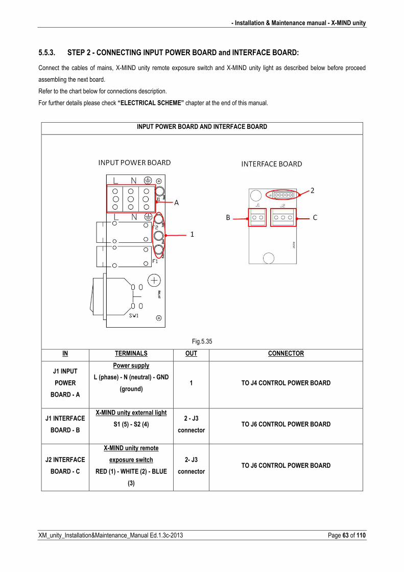
5.5.3. STEP 2 � CONNECTING INPUT POWER BOARD and INTERFACE BOARD:
Connect the cables of mains, XMIND unity remote exposure switch and XMIND unity light as described below before proceed
assembling the next board.
Refer to the chart below for connections description.
For further details please check “ELECTRICAL SCHEME” chapter at the end of this manual.
INPUT POWER BOARD AND INTERFACE BOARD
Fig.5.35
IN TERMINALS OUT CONNECTOR
J1 INPUT
POWER
BOARD � A
Power supply
L (phase) � N (neutral) � GND
(ground)
1 TO J4 CONTROL POWER BOARD
J1 INTERFACE
BOARD � B
X�MIND unity external light
S1 (5) � S2 (4)
2 � J3
connector TO J6 CONTROL POWER BOARD
J2 INTERFACE
BOARD � C
X�MIND unity remote
exposure switch
RED (1) � WHITE (2) � BLUE
(3)
2� J3
connector TO J6 CONTROL POWER BOARD
X�MIND unity � Installation & Maintenance manual �
Page 64 of 110 XM_unity_Installation&Maintenance_Manual Ed.1.3c2013
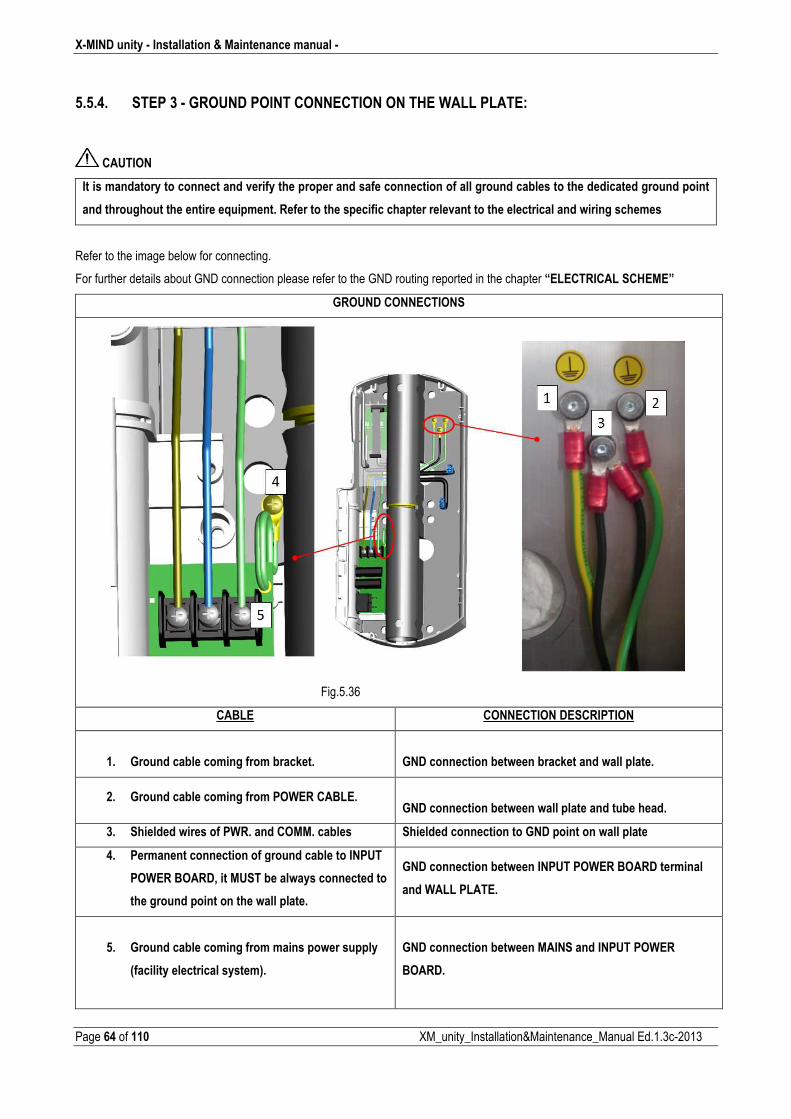
5.5.4. STEP 3 � GROUND POINT CONNECTION ON THE WALL PLATE:
CAUTION
It is mandatory to connect and verify the proper and safe connection of all ground cables to the dedicated ground point
and throughout the entire equipment. Refer to the specific chapter relevant to the electrical and wiring schemes �
Refer to the image below for connecting.
For further details about GND connection please refer to the GND routing reported in the chapter “ELECTRICAL SCHEME”
GROUND CONNECTIONS
Fig.5.36
CABLE CONNECTION DESCRIPTION
1. Ground cable coming from bracket.
GND connection between bracket and wall plate.
2. Ground cable coming from POWER CABLE.
GND connection between wall plate and tube head.
3. Shielded wires of PWR. and COMM. cables Shielded connection to GND point on wall plate
4. Permanent connection of ground cable to INPUT
POWER BOARD, it MUST be always connected to
the ground point on the wall plate.
GND connection between INPUT POWER BOARD terminal
and WALL PLATE.
5. Ground cable coming from mains power supply
(facility electrical system).
GND connection between MAINS and INPUT POWER
BOARD.
� Installation & Maintenance manual � X�MIND unity
XM_unity_Installation&Maintenance_Manual Ed.1.3c2013 Page 65 of 110
5.5.5. STEP 4 � INSTALL AND CONNECT REMOTE EXPOSURE SWITCH AND X�MIND unity LIGHT
(Optional)
REFER TO CHAPTERS 6 and 7 for instructions otherwise proceed to the next step.
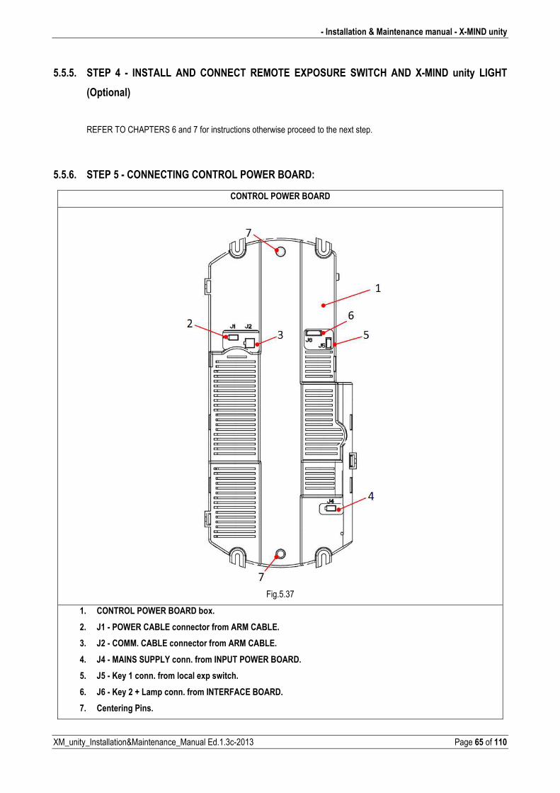
5.5.6. STEP 5 � CONNECTING CONTROL POWER BOARD:
CONTROL POWER BOARD
Fig.5.37
1. CONTROL POWER BOARD box.
2. J1 � POWER CABLE connector from ARM CABLE.
3. J2 � COMM. CABLE connector from ARM CABLE.
4. J4 � MAINS SUPPLY conn. from INPUT POWER BOARD.
5. J5 � Key 1 conn. from local exp switch.
6. J6 � Key 2 + Lamp conn. from INTERFACE BOARD.
7. Centering Pins.
X�MIND unity � Installation & Maintenance manual �
Page 66 of 110 XM_unity_Installation&Maintenance_Manual Ed.1.3c2013
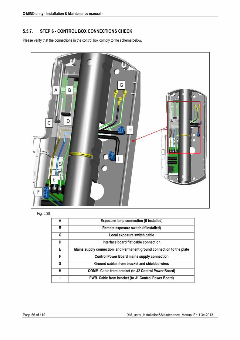
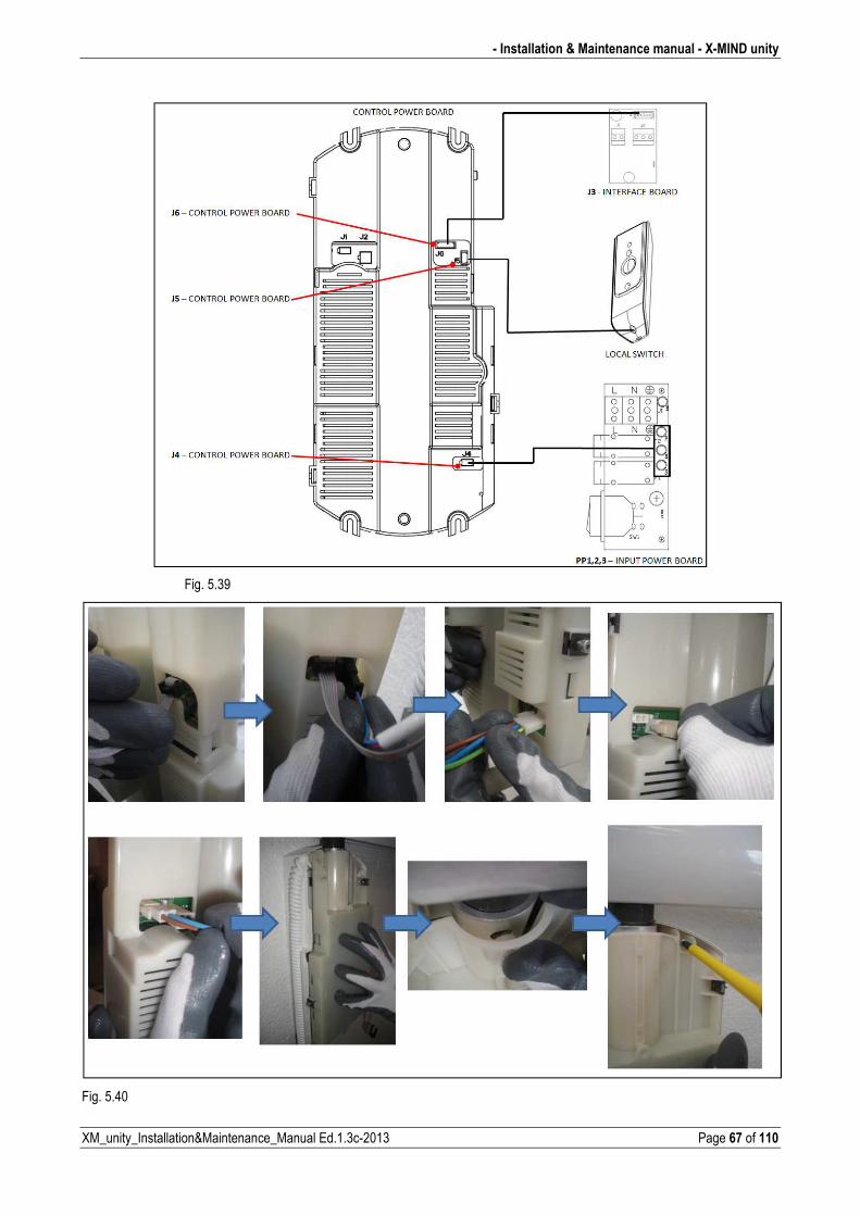
5.5.7. STEP 6 � CONTROL BOX CONNECTIONS CHECK
Please verify that the connections in the control box comply to the scheme below.
Fig. 5.38
A Exposure lamp connection (if installed)
B Remote exposure switch (if installed)
C Local exposure switch cable
D Interface board flat cable connection
E Mains supply connection and Permanent ground connection to the plate
F Control Power Board mains supply connection
G Ground cables from bracket and shielded wires
H COMM. Cable from bracket (to J2 Control Power Board)
I PWR. Cable from bracket (to J1 Control Power Board)
� Installation & Maintenance manual � X�MIND unity
XM_unity_Installation&Maintenance_Manual Ed.1.3c2013 Page 67 of 110
Fig. 5.39
Fig. 5.40
X�MIND unity � Installation & Maintenance manual �
Page 68 of 110 XM_unity_Installation&Maintenance_Manual Ed.1.3c2013
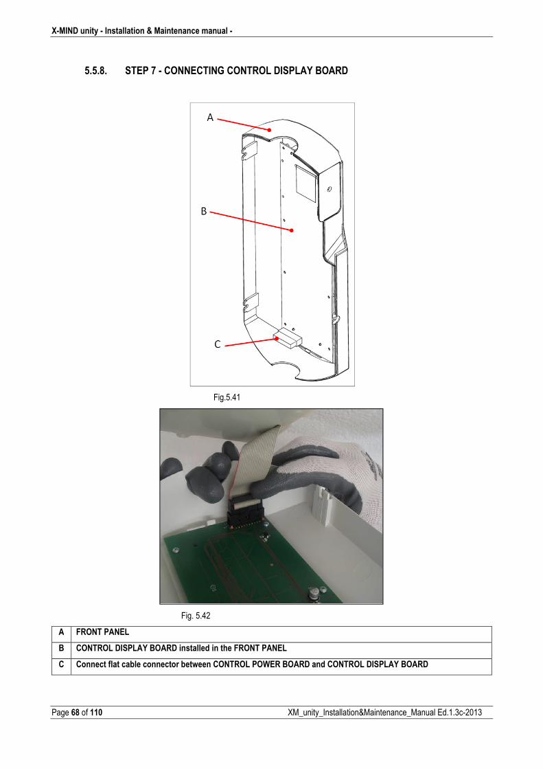
5.5.8. STEP 7 � CONNECTING CONTROL DISPLAY BOARD
Fig.5.41
Fig. 5.42
A FRONT PANEL
B CONTROL DISPLAY BOARD installed in the FRONT PANEL
C Connect flat cable connector between CONTROL POWER BOARD and CONTROL DISPLAY BOARD
� Installation & Maintenance manual � X�MIND unity
XM_unity_Installation&Maintenance_Manual Ed.1.3c2013 Page 69 of 110
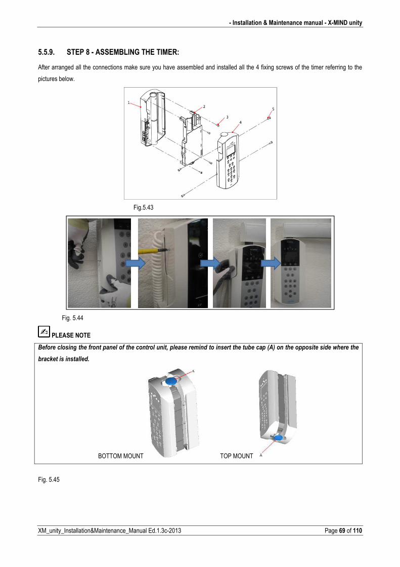
5.5.9. STEP 8 � ASSEMBLING THE TIMER:
After arranged all the connections make sure you have assembled and installed all the 4 fixing screws of the timer referring to the
pictures below.
Fig.5.43
Fig. 5.44
PLEASE NOTE
-�������������������������������������������������+�������������������������������*������12��������������������������������
*���)�����������������
BOTTOM MOUNT TOP MOUNT
Fig. 5.45
X�MIND unity � Installation & Maintenance manual �
Page 70 of 110 XM_unity_Installation&Maintenance_Manual Ed.1.3c2013
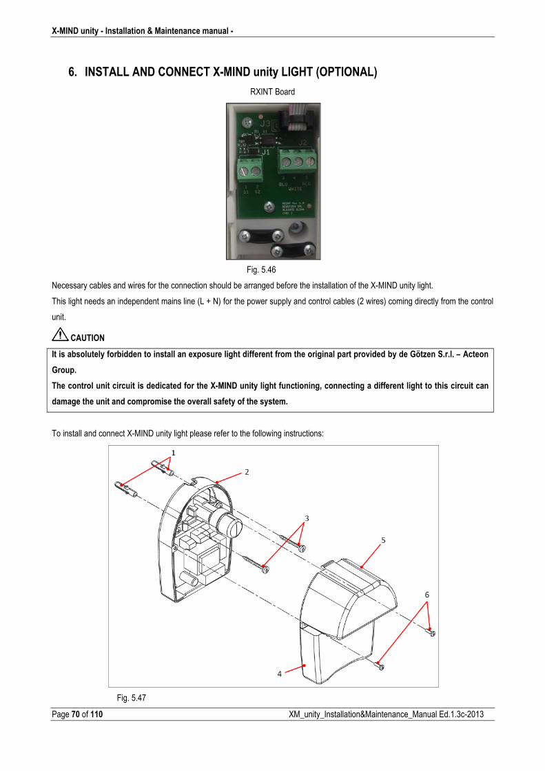
6. INSTALL AND CONNECT X�MIND unity LIGHT (OPTIONAL)
RXINT Board
Fig. 5.46
Necessary cables and wires for the connection should be arranged before the installation of the XMIND unity light.
This light needs an independent mains line (L + N) for the power supply and control cables (2 wires) coming directly from the control
unit.
CAUTION
It is absolutely forbidden to install an exposure light different from the original part provided by de Götzen S.r.l. – Acteon
Group.
The control unit circuit is dedicated for the X�MIND unity light functioning, connecting a different light to this circuit can
damage the unit and compromise the overall safety of the system.
To install and connect XMIND unity light please refer to the following instructions:
Fig. 5.47
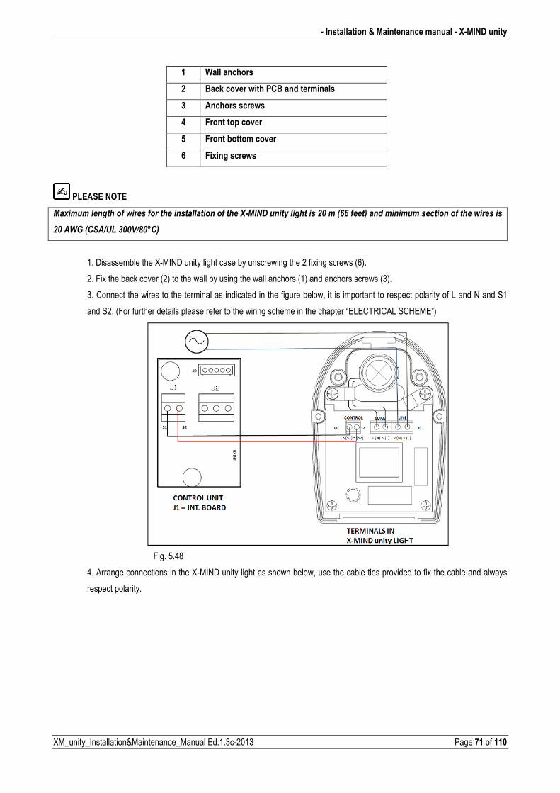
� Installation & Maintenance manual � X�MIND unity
XM_unity_Installation&Maintenance_Manual Ed.1.3c2013 Page 71 of 110
1 Wall anchors
2 Back cover with PCB and terminals
3 Anchors screws
4 Front top cover
5 Front bottom cover
6 Fixing screws
PLEASE NOTE
0�"�������������������������������������������������9#0��,����������������>@���1AA�����2�������������������������������������
>@��!�1'8�%�5@@38B@C2�
1. Disassemble the XMIND unity light case by unscrewing the 2 fixing screws (6).
2. Fix the back cover (2) to the wall by using the wall anchors (1) and anchors screws (3).
3. Connect the wires to the terminal as indicated in the figure below, it is important to respect polarity of L and N and S1
and S2. (For further details please refer to the wiring scheme in the chapter “ELECTRICAL SCHEME”)
Fig. 5.48
4. Arrange connections in the XMIND unity light as shown below, use the cable ties provided to fix the cable and always
respect polarity.
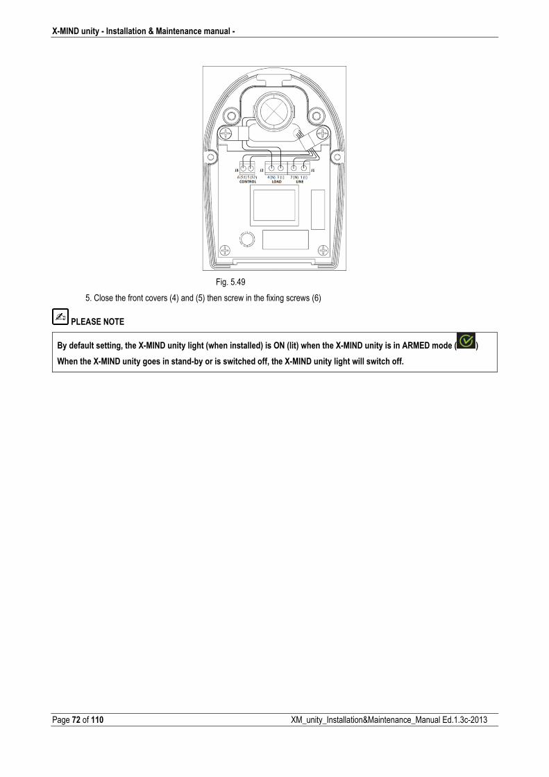
X�MIND unity � Installation & Maintenance manual �
Page 72 of 110 XM_unity_Installation&Maintenance_Manual Ed.1.3c2013
Fig. 5.49
5. Close the front covers (4) and (5) then screw in the fixing screws (6)
PLEASE NOTE
By default setting, the X�MIND unity light (when installed) is ON (lit) when the X�MIND unity is in ARMED mode ( )
When the X�MIND unity goes in stand�by or is switched off, the X�MIND unity light will switch off.
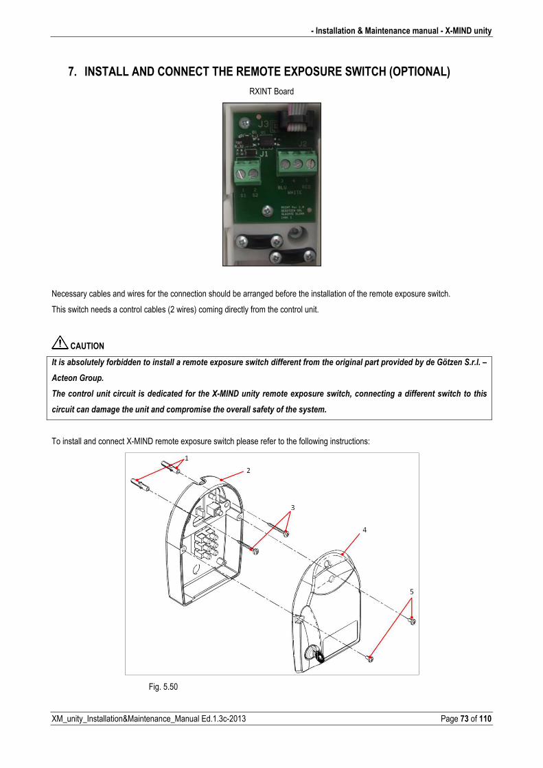
� Installation & Maintenance manual � X�MIND unity
XM_unity_Installation&Maintenance_Manual Ed.1.3c2013 Page 73 of 110
7. INSTALL AND CONNECT THE REMOTE EXPOSURE SWITCH (OPTIONAL)
RXINT Board
Necessary cables and wires for the connection should be arranged before the installation of the remote exposure switch.
This switch needs a control cables (2 wires) coming directly from the control unit.
CAUTION
�������*������������*���������������������������"��������������������������������������������������(�����*�����!D�E���'������F�
������!������
������������������������� ����������������� ����9#0��,������� ��������"�������������+���������������������������������������
������������������������������������������������(����������������������������
To install and connect XMIND remote exposure switch please refer to the following instructions:
Fig. 5.50
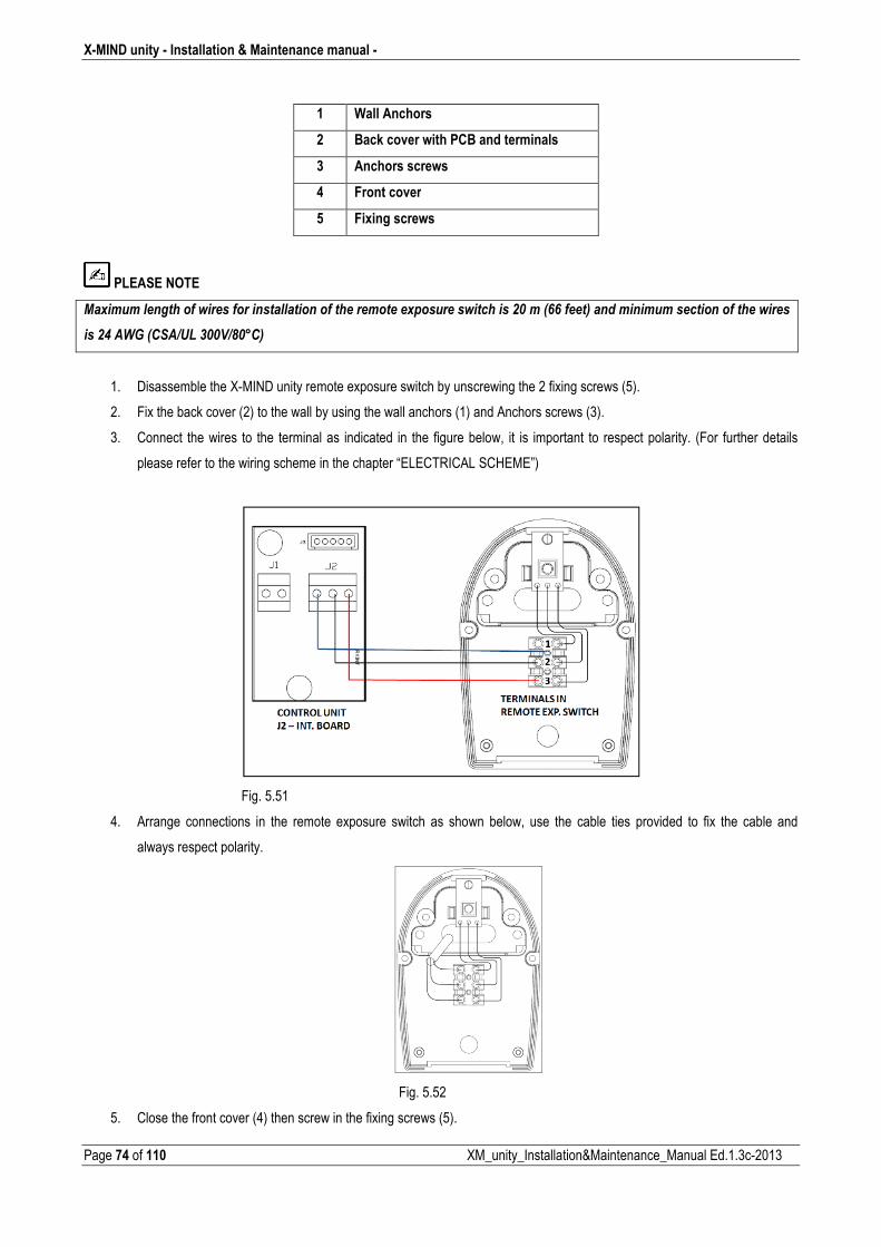
X�MIND unity � Installation & Maintenance manual �
Page 74 of 110 XM_unity_Installation&Maintenance_Manual Ed.1.3c2013
1 Wall Anchors
2 Back cover with PCB and terminals
3 Anchors screws
4 Front cover
5 Fixing screws
PLEASE NOTE
0�"�����������������������������������������������������"�����������������>@���1AA�����2����������������������������������
���>G��!�1'8�%�5@@38B@C2�
1. Disassemble the XMIND unity remote exposure switch by unscrewing the 2 fixing screws (5).
2. Fix the back cover (2) to the wall by using the wall anchors (1) and Anchors screws (3).
3. Connect the wires to the terminal as indicated in the figure below, it is important to respect polarity. (For further details
please refer to the wiring scheme in the chapter “ELECTRICAL SCHEME”)
Fig. 5.51
4. Arrange connections in the remote exposure switch as shown below, use the cable ties provided to fix the cable and
always respect polarity.
Fig. 5.52
5. Close the front cover (4) then screw in the fixing screws (5).
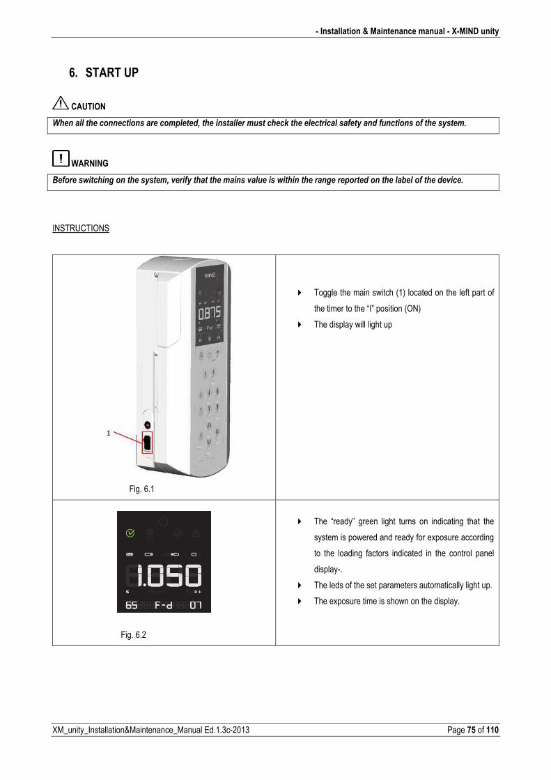
� Installation & Maintenance manual � X�MIND unity
XM_unity_Installation&Maintenance_Manual Ed.1.3c2013 Page 75 of 110
6. START UP
CAUTION
��������������������������������������+������������������������)���������������������������������������������������
WARNING
-�����������������������������+�(���������������������(�������������������������������������������*������������(����
INSTRUCTIONS
Fig. 6.1
� Toggle the main switch (1) located on the left part of
the timer to the “I” position (ON)
� The display will light up
Fig. 6.2
� The “ready” green light turns on indicating that the
system is powered and ready for exposure according
to the loading factors indicated in the control panel
display.
� The leds of the set parameters automatically light up.
� The exposure time is shown on the display.
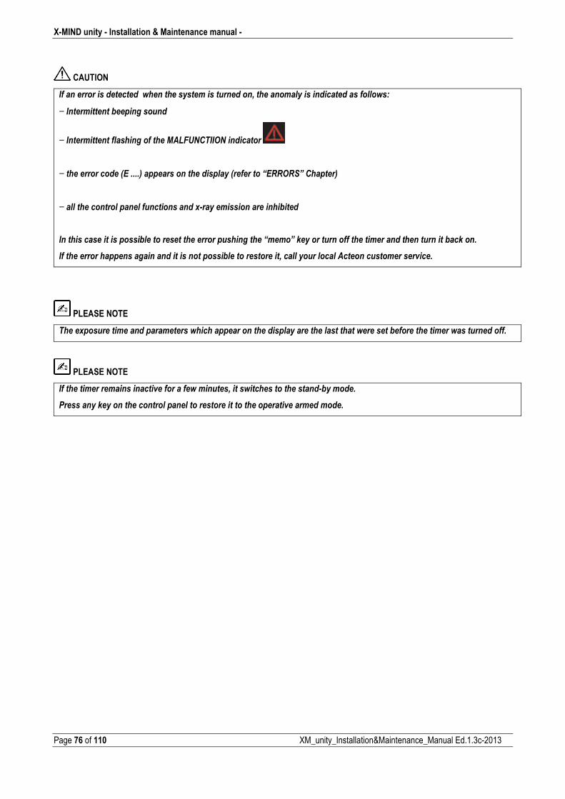
X�MIND unity � Installation & Maintenance manual �
Page 76 of 110 XM_unity_Installation&Maintenance_Manual Ed.1.3c2013
CAUTION
�����������������������������������������������������+������������������������������������7��
− �������������*�������������
− �����������������������������0%4����� ������������ �
��
− ���������������1&�����2������������������������1���������H& '?�������2�
�
− ������������������������������������"#���������������������*�����
�
������������������������*����������������������������������H����?�)������������������������������������������*��)�����
����������������������������������������������*����������������+�����������������������������������(�����
PLEASE NOTE
�����"����������������������������������������������������������������������������������*��������������������������������
PLEASE NOTE
���������������������������(�������������������+�������������������������#*���������
$���������)����������������������������������������������������(��������������

� Installation & Maintenance manual � X�MIND unity
XM_unity_Installation&Maintenance_Manual Ed.1.3c2013 Page 77 of 110
7. CONFIGURATION
The “X�MIND unity“ xray system is factory configured in “;"5#'56'�3!'(”.
On the control panel, the led relevant to the following exposure parameters will light up:
Ready for xray exposure (Armed mode)
XRay Exposure Time selected
Type of cone installed (rectangular or circular shaped xray beam output)
SSD distance
20 [cm] (8”) = SHORT CONE (circular or rectangular)
30 [cm] (12”) = LONG CONE (circular or rectangular)
Xray tube voltage
60kV / 65kV / 70kV
Xray tube current
4mA7mA
Selection of the xray detector support type :
Fd : FILM, D Speed
Fe : FILM, E Speed
Ff : FILM, F Speed
Dig : Digital XRay Sensor
PSP : Phosphor plates
ACE : The “ACE” code inside the list of selected type of supported detector (Fd, Fe, Fg, Ff, DIG,
PSP) is available only when a Sopix/Sopix2 Inside is installed and properly armed.
When the integrated SOPIX/SOPIX2 Inside sensor is installed and properly armed you can run the
XMIND unity with the ACE system activated2. This icon lights up after the exposure performed in
ACE mode.
2 Refer to the operator’s manual of the SOPIX/SOPIX22 Inside xray sensor for more informations or contact the technical support of Sopro. : ZAC Athélia IV • Avenue des Genévriers • 13705 LA CIOTAT cedex • FRANCE • Tél +33 (0) 442 98 01 01 • Fax +33 (0) 442 71 76 90 • Email: [email protected] • www.sopro.acteongroup.com
X�MIND unity � Installation & Maintenance manual �
Page 78 of 110 XM_unity_Installation&Maintenance_Manual Ed.1.3c2013
The following exposure times [s] are available in the XMIND unity: 0.020 – 0,025 – 0,032 – 0,040 – 0,050 – 0,063 – 0,080 – 0,100 –0,125 – 0,160 – 0,200 – 0,250 – 0,320 – 0,400 – 0,500 –0,630 – 0,800 – 1,00 – 1,250 – 1,600 – 2,000 s
PLEASE NOTE
������������������������������������&�A@A@I#>#<����������������������������>�������5�������������������&�A@A@I#I����������������' �G=<�������� �I@�������������������
PLEASE NOTE
������(�������������������������"�������������0:�� ��*������������ Certain exposure values have been predefined which depend on the selection of the operating parameters: � cone (8”/12”)
� type of patient (ADULT/CHILD)
� xray technique
� intraoral exam
PLEASE NOTE
�����������������+������������*�������������������(������*�������������������������)���*����������(������������������ Possible modifications of the exposure values: � xray anodic voltage (typical: 60kV/65kV/70kV)
� xray anodic current (typical: 4mA/6mA/7mA)
� type of patient (ADULT/CHILD)
� xray technique
���� refer to chapter 5 Possible modifications of the parameters: � Number of exposure switches
� Cone size (20cm 8” / 30cm 12”)
� Cone type (Square / Round)
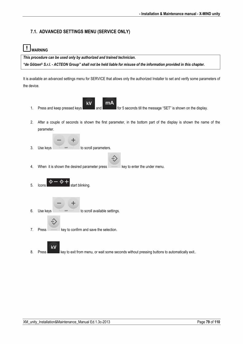
� Installation & Maintenance manual � X�MIND unity
XM_unity_Installation&Maintenance_Manual Ed.1.3c2013 Page 79 of 110
7.1. ADVANCED SETTINGS MENU (SERVICE ONLY)
WARNING
�������������������*������������*���������E���������������������������
H���!D�E��J�'������#��& ��!����?�����������*����������*������������������������������������(����������������������
It is available an advanced settings menu for SERVICE that allows only the authorized Installer to set and verify some parameters of
the device.
1. Press and keep pressed keys and for 5 seconds till the message “SET” is shown on the display.
2. After a couple of seconds is shown the first parameter, in the bottom part of the display is shown the name of the
parameter.
3. Use keys to scroll parameters.
4. When it is shown the desired parameter press key to enter the under menu.
5. Icons start blinking.
6. Use keys to scroll available settings.
7. Press key to confirm and save the selection.
8. Press key to exit from menu, or wait some seconds without pressing buttons to automatically exit..

X�MIND unity � Installation & Maintenance manual �
Page 80 of 110 XM_unity_Installation&Maintenance_Manual Ed.1.3c2013
SERVICE MENU � AVAILABLE SETTINGS
IDENTIFICATION DESCRIPTION RANGE CUSTOMIZABLE
����� ������� Restore factory time Yes / No Yes
&������%��� See errors list Scroll errors Clear errors list
��������� Cone type installed / selected
Short cone
Long cone
Rectangular cone
Yes3
������*������ Wired remote switch enable ON/OFF Yes
&������8�#!� Number of exposure (tens) 0….9999 (Read only) No
��������8#!� Number of powerup (tens) 0….9999 (Read only) No
%����0���� Define Exp. Light functioning
rdy (ON when in armed
mode)
EMIS (ON during exp.)
Yes
%��������� Verify functioning of leds Start test only Start test only
,������������ Verify functioning of display Start test only Start test only
K��������� Verify functioning of keys Start test only Start test only
3������� Control unit firmware version Read only No
����������(��� XRay Source assembly firmware version Read only No
��Only authorized installers and technicians are authorized to modify the cone configuration�
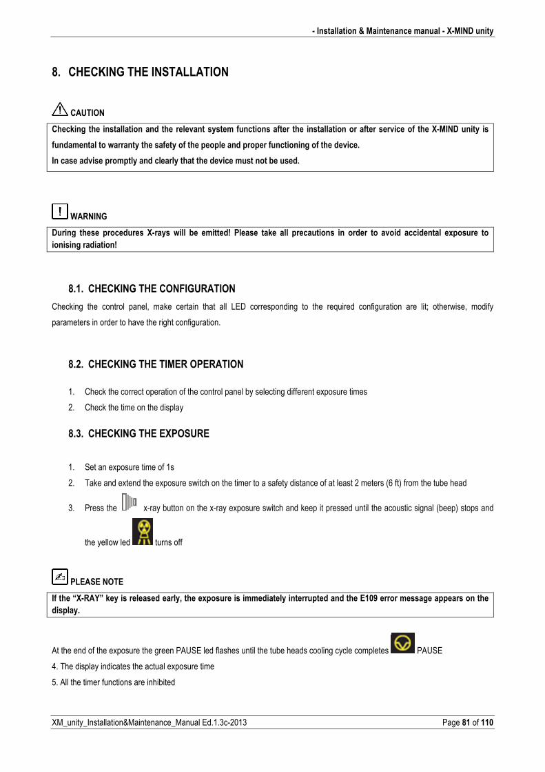
� Installation & Maintenance manual � X�MIND unity
XM_unity_Installation&Maintenance_Manual Ed.1.3c2013 Page 81 of 110
8. CHECKING THE INSTALLATION
CAUTION
Checking the installation and the relevant system functions after the installation or after service of the X�MIND unity is
fundamental to warranty the safety of the people and proper functioning of the device.
In case advise promptly and clearly that the device must not be used.
WARNING
During these procedures X�rays will be emitted! Please take all precautions in order to avoid accidental exposure to
ionising radiation!
8.1. CHECKING THE CONFIGURATION
Checking the control panel, make certain that all LED corresponding to the required configuration are lit; otherwise, modify
parameters in order to have the right configuration.
8.2. CHECKING THE TIMER OPERATION
�
1. Check the correct operation of the control panel by selecting different exposure times
2. Check the time on the display
8.3. CHECKING THE EXPOSURE
1. Set an exposure time of 1s
2. Take and extend the exposure switch on the timer to a safety distance of at least 2 meters (6 ft) from the tube head
3. Press the xray button on the xray exposure switch and keep it pressed until the acoustic signal (beep) stops and
the yellow led turns off
PLEASE NOTE
If the “X�RAY” key is released early, the exposure is immediately interrupted and the E109 error message appears on the
display.
At the end of the exposure the green PAUSE led flashes until the tube heads cooling cycle completes PAUSE
4. The display indicates the actual exposure time
5. All the timer functions are inhibited
X�MIND unity � Installation & Maintenance manual �
Page 82 of 110 XM_unity_Installation&Maintenance_Manual Ed.1.3c2013
8.4. CHECKING THE OPERATION OF THE TUBEHEAD
take several exposures and check that: � there are no errors
� the led of the selected tube head is lit
� the exposure button switch led is lit over the whole duration of the acoustic signal (beep)
8.5. CHECKING THE ABSORBED POWER
To check the power absorbed by the radiographic system an AC ammeter must be used
�� Connect the instrument to the power supply line���
2. Set the xray to 65kV 7mA 2 s on the control panel
3. Carry out an exposure and read the current value on the instrument
PLEASE NOTE
������������������������9#0��,���������������������������/��������������7�
�����*���*���������������≤≤≤≤��B+L������I@@�#�>G@�3���������(����� ��������+�����)�������������������������������������������������'��(�������*������������������5����������������
8.6. CHECKING THE ELECTRIC SYSTEM
To check the electrical system an AC voltmeter must be used:
1. Measure the voltage from mains terminals
2. Measure and record the line voltage
3. Set an exposure of 65kV 7mA 2 s on the control panel
4. Proceed to the exposure and measured the line voltage during exposure
PLEASE NOTE
����������������������������������������/��������������7�
13@�F�3I�2�8�3@�����≤≤≤≤�@+@5��
��������+�����)�������������������������������������������������'��(�������*������������������5����������������

� Installation & Maintenance manual � X�MIND unity
XM_unity_Installation&Maintenance_Manual Ed.1.3c2013 Page 83 of 110
9. BASICAL CHECKING OVERALL SYSTEM FUNCTIONS
PLEASE NOTE
$�������������������0�����������������������0�������������������������������)���
PARTS CHECK DESCRIPTION X
WALL MOUNTING
Ensure that the wall support is adequate, the system is
properly installed to the wall and fixing anchors are properly
tighten.
LABELS CHECKING
Ensure that all the labels on the system are available and
properly attached.
Furthermore check that they are readable and correct with the
SN reported on the documents.
SYSTEM ROTATING PARTS Ensure that all rotating parts have a functioning mechanical
stop to avoid cables twisting.
SYSTEM STABILITY
Check that all the movements are smooth and no forcing.
Check that the system maintains the position without further
movements after releasing it.
COVERS INSTALLATION
Ensure that all the enclosures and covers are properly
installed (including all the screw caps) and not damaged. Make
sure the bottom slide cover of the bracket is properly installed.
POWER SWITCH FUNCTIONING Verify that the power switch is properly functioning and that
the power indicator is lit on the control panel.
CONTROL PANEL FUNCTIONING When the system is ON, verify that all the buttons and settings
are functioning and available.
LOCAL AND *REMOTE EXPOSURE BUTTON
* if installed
Verify that the exposure buttons are functioning properly,
check also exposure LED located on the switches.
EXPOSURE INDICATORS
Make several exposures and verify that the exposures
indicators are functioning.(icon on the control panel, led on
exposure button and audible signal from control unit)
EXPOSURE INTERRUPTION
Select longest exposure time available and using “+” button.
Start an exposure but release switch before the end of the
exposure. Verify that the display shows an error and
malfunction indicator is ON.
Pressing “Clear” button the system back to normal operation.
OPERATOR INFORMATION
Ensure that the Operator has received the whole
documentation provided with the system and the necessary
information in order to operate the system according to safety
measures.
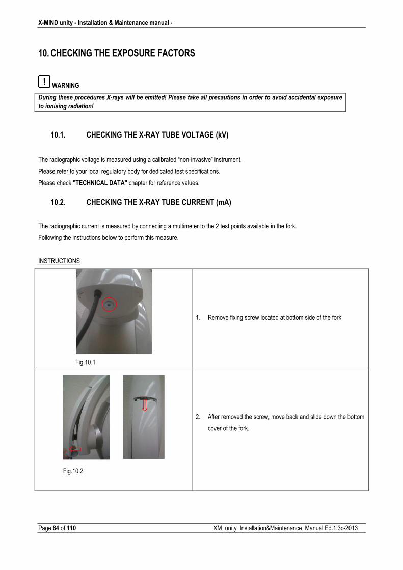
X�MIND unity � Installation & Maintenance manual �
Page 84 of 110 XM_unity_Installation&Maintenance_Manual Ed.1.3c2013
10. CHECKING THE EXPOSURE FACTORS
WARNING
,�����������������������9#����������*���������6�$��������)�������������������������������(����������������"�������
���������������������6�
10.1. CHECKING THE X�RAY TUBE VOLTAGE (kV)
The radiographic voltage is measured using a calibrated “noninvasive” instrument.
Please refer to your local regulatory body for dedicated test specifications.
Please check "TECHNICAL DATA" chapter for reference values.
10.2. CHECKING THE X�RAY TUBE CURRENT (mA)
�
The radiographic current is measured by connecting a multimeter to the 2 test points available in the fork.
Following the instructions below to perform this measure.
INSTRUCTIONS
Fig.10.1
1. Remove fixing screw located at bottom side of the fork.
Fig.10.2
2. After removed the screw, move back and slide down the bottom
cover of the fork.
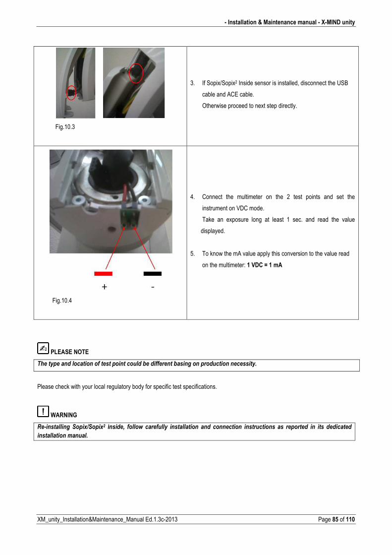
� Installation & Maintenance manual � X�MIND unity
XM_unity_Installation&Maintenance_Manual Ed.1.3c2013 Page 85 of 110
Fig.10.3
3. If Sopix/Sopix2 Inside sensor is installed, disconnect the USB
cable and ACE cable.
Otherwise proceed to next step directly.
Fig.10.4
4. Connect the multimeter on the 2 test points and set the
instrument on VDC mode.
Take an exposure long at least 1 sec. and read the value
displayed.
5. To know the mA value apply this conversion to the value read
on the multimeter: 1 VDC = 1 mA
PLEASE NOTE
������������������������������������������*������������*�������������������������������
Please check with your local regulatory body for specific test specifications.
WARNING
�#����������� '���"8'���">� ������+� ������� ���������� ������������� ���� ����������� ������������� ��� ��������� ��� ���� ����������
���������������������
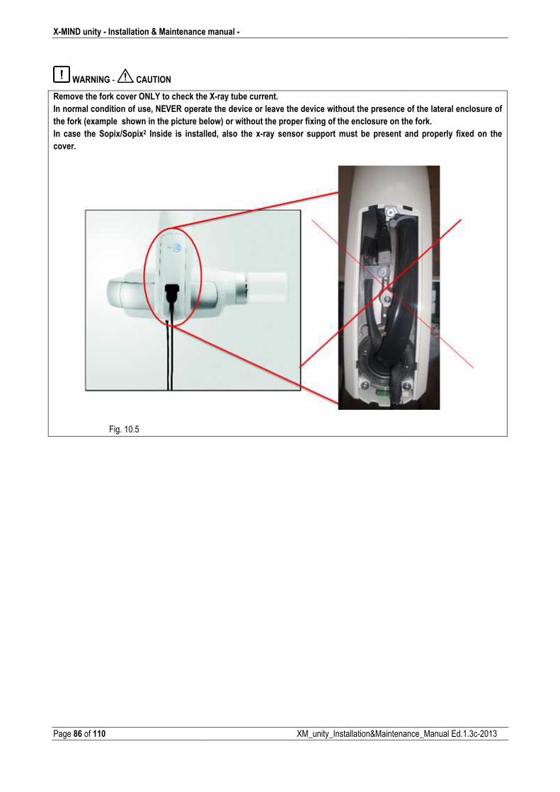
X�MIND unity � Installation & Maintenance
Page 86 of 110
WARNING CAUTION
Remove the fork cover ONLY to check the
In normal condition of use, NEVER opera
the fork (example shown in the picture be
In case the Sopix/Sopix2 Inside is instal
cover.
�
Fig. 10.5
ce manual �
XM_unity_Installation&Maintena
the X�ray tube current.
erate the device or leave the device without the presence
below) or without the proper fixing of the enclosure on th
talled, also the x�ray sensor support must be present a
nance_Manual Ed.1.3c2013
ce of the lateral enclosure of
the fork.
t and properly fixed on the
�
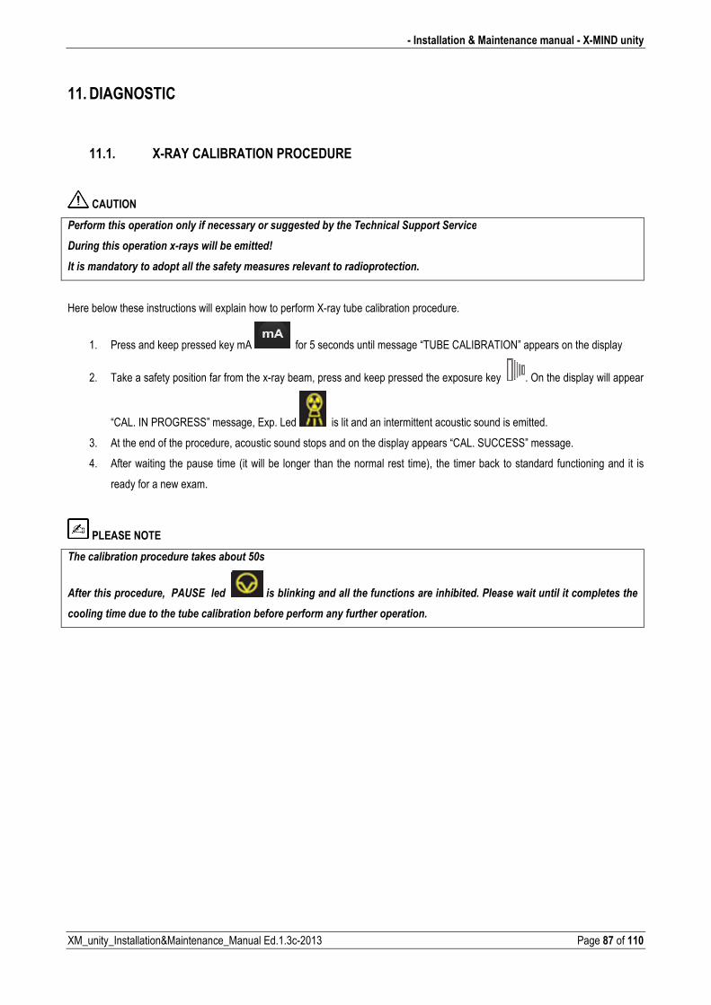
� Installation & Maintenance manual � X�MIND unity
XM_unity_Installation&Maintenance_Manual Ed.1.3c2013 Page 87 of 110
11. DIAGNOSTIC
11.1. X�RAY CALIBRATION PROCEDURE
CAUTION
$�����������������������������������������������������*����������������'�������'��(����
,���������������������"#����������*���������6�
�����������������������������������������������������(������������������������
Here below these instructions will explain how to perform Xray tube calibration procedure.
1. Press and keep pressed key mA for 5 seconds until message “TUBE CALIBRATION” appears on the display
2. Take a safety position far from the xray beam, press and keep pressed the exposure key . On the display will appear
“CAL. IN PROGRESS” message, Exp. Led is lit and an intermittent acoustic sound is emitted.
3. At the end of the procedure, acoustic sound stops and on the display appears “CAL. SUCCESS” message.
4. After waiting the pause time (it will be longer than the normal rest time), the timer back to standard functioning and it is
ready for a new exam.
PLEASE NOTE
��������*�������������������)����*����L@��
�������������������+��$�'&������� ����*���)����������������������������������*������$����������������������������������
��������������������������*������*�������*���������������������������������������
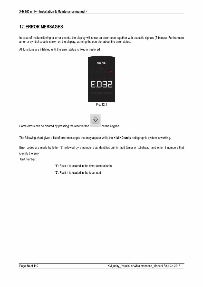
X�MIND unity � Installation & Maintenance manual �
Page 88 of 110 XM_unity_Installation&Maintenance_Manual Ed.1.3c2013
12. ERROR MESSAGES
�
In case of malfunctioning or error events, the display will show an error code together with acoustic signals (5 beeps). Furthermore an error symbol code is shown on the display, warning the operator about the error status. All functions are inhibited until the error status is fixed or restored.
Fig. 12.1
Some errors can be cleared by pressing the reset button on the keypad. The following chart gives a list of error messages that may appear while the X�MIND unity radiographic system is working.
Error codes are made by letter “E” followed by a number that identifies unit in fault (timer or tubehead) and other 2 numbers that
identify the error.
Unit number:
“1”: Fault it is located in the timer (control unit)
“2”: Fault it is located in the tubehead

� Installation & Maintenance manual � X�MIND unity
XM_unity_Installation&Maintenance_Manual Ed.1.3c2013 Page 89 of 110
This chart also includes the causes of the error messages and what to do to solve them:
Code Message Description Resettable
E101 memory fail EEPROM fault NO
E102 memory fail I2C bus EEPROM fault NO
E103 memory fail EEPROM DMA readings fault NO
E104 memory fail EEPROM DMA writings fault NO
E105 no response from generator Lost communication between inverter and generator
NO
E106 wrong response from generator NAK response from inverter YES
E107 emission start fail YES
E108 emission too long YES
E109 button released beforehand YES
E110 wrong use of button pressione pulsante di esposizione in situazione di “pronto” disattivo
YES
E111 keyboard pressed at boot Keyboard pressed during boot time NO
E112 button pushed at boot Exposure button pressed beforehand NO
E113 wrong use of keyboard Keys pressed during an exposure YES
E114 button release timeout Exposure button released beforehand after an exposure
YES
E115 wrong parameters in generator Exposure parameters (kV, mA, exposure time, mode) does not match with the ones set in the control box
YES
E116 generator reset during emission inverter has been resetted during an exposure
YES
E117 calibration start fail Calibration YES
E118 calibration too long Calibration tme too long YES
E119 button pushed during cooling Exposure button pressed beforehand pushed during a functionality exposure
YES
E120 cooling time disabled Functionality pause disabled YES
E121 button pushed during standby Exposure button pressed beforehand during standby
YES
E122 memory fail Parameters out of range NO
E123 power relay fail power relay failure (relay OFF) NO
E124 power relay fail power relay failure (relay ON) NO
E125 power board fail power board failure NO
E126 power board fail power board failure NO
E127 power board fail power board failure NO
E128 power board fail power board failure NO
E201 generator memory Inverter EEPROM error NO
E202 generator memory Inverter I2C EEPROM error NO
E203 generator memory Inverter EEPROM DMA readings fault NO
E204 generator memory Inverter EEPROM DMA writings fault NO

X�MIND unity � Installation & Maintenance manual �
Page 90 of 110 XM_unity_Installation&Maintenance_Manual Ed.1.3c2013
Code Message Description Resettable
E205 generator not calibrated Calibration not yet done YES
E206 tube voltage too low Anodic voltage too low YES
E207 tube voltage too high Anodic voltage too high YES
E208 electrical discharge on hv YES
E209 tube current too low Anodic current too low YES
E210 tube current too high Anodic current too high YES
E211 filament voltage too low Filament voltage too low YES
E212 filament voltage too high Filament voltage too high YES
E213 tube unit not connected High voltage unit not connected NO
E214 button released beforehand Enable signal released beforehand during an exposure
YES
E215 generator internal power supply 12V internal voltage too low NO
E216 generator internal power supply 12V internal voltage too high NO
E217 generator mode Wrong exposure enabling signal activation
YES
E218 safe circuit fail Security interlock fault NO
E219 tube current too low Mean anodic current too low YES
E220 tube current too high Mean anodic current too high YES
E221 no tube voltage feedback Missing HV feedback NO
E222 ACE acquisition fail Xrays not detected by Sopix YES
For the errors that can’t be cleared by the reset button on the keypad, please contact your installer or your local Acteon customer service
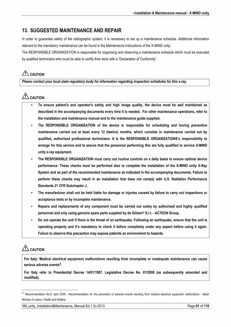
� Installation & Maintenance manual � X�MIND unity
XM_unity_Installation&Maintenance_Manual Ed.1.3c2013 Page 91 of 110
13. SUGGESTED MAINTENANCE AND REPAIR
In order to guarantee safety of the radiographic system, it is necessary to set up a maintenance schedule. Additional information
relevant to the mandatory maintenance can be found in the Maintenance Instructions of the XMIND unity.
The RESPONSIBLE ORGANIZATION is responsible for organising and observing a maintenance schedule which must be executed
by qualified technicians who must be able to certify their work with a “Declaration of Conformity”.
CAUTION
$������������������������������������������*������������������������������������������������������������"#�����
CAUTION
• To ensure patient's and operator's safety and high image quality, the device must be well maintained as
described in the accompanying documents every time it is needed. For other maintenance operations, refer to
the installation and maintenance manual and to the maintenance guide supplied.
• The RESPONSIBLE ORGANIZATION of the device is responsible for scheduling and having preventive
maintenance carried out at least every 12 (twelve) months, which consists in maintenance carried out by
qualified, authorised professional technicians. It is the RESPONSIBLE ORGANIZATIONS’s responsibility to
arrange for this service and to assure that the personnel performing this are fully qualified to service X�MIND
unity x�ray equipment.
• The RESPONSIBLE ORGANIZATION must carry out routine controls on a daily basis to ensure optimal device
performance. These checks must be performed also to complete the installation of the X�MIND unity X�Ray
System and as part of the recommended maintenance as indicated in the accompanying documents. Failure to
perform these checks may result in an installation that does not comply with U.S. Radiation Performance
Standards 21 CFR Subchapter J.
• The manufacturer shall not be held liable for damage or injuries caused by failure to carry out inspections or
acceptance tests or by incomplete maintenance.
• Repairs and replacements of any component must be carried out solely by authorised and highly qualified
personnel and only using genuine spare parts supplied by de Götzen® S.r.l. � ACTEON Group.
• Do not operate the unit if there is the threat of an earthquake. Following an earthquake, ensure that the unit is
operating properly and it’s mandatory to check it before completely under any aspect before using it again.
Failure to observe this precaution may expose patients an environment to hazards.
CAUTION
For Italy: Medical electrical equipment malfunctions resulting from incomplete or inadequate maintenance can cause
serious adverse eventsG.�
For Italy refer to Presidential Decree 14/01/1997, Legislative Decree No. 81/2008 (as subsequently amended and
modified).
��Recommendation No.9, April 2009 Recommendation for the prevention of adverse events resulting from medical electrical equipment malfunctions Italian
Ministry of Labour, Health and Welfare
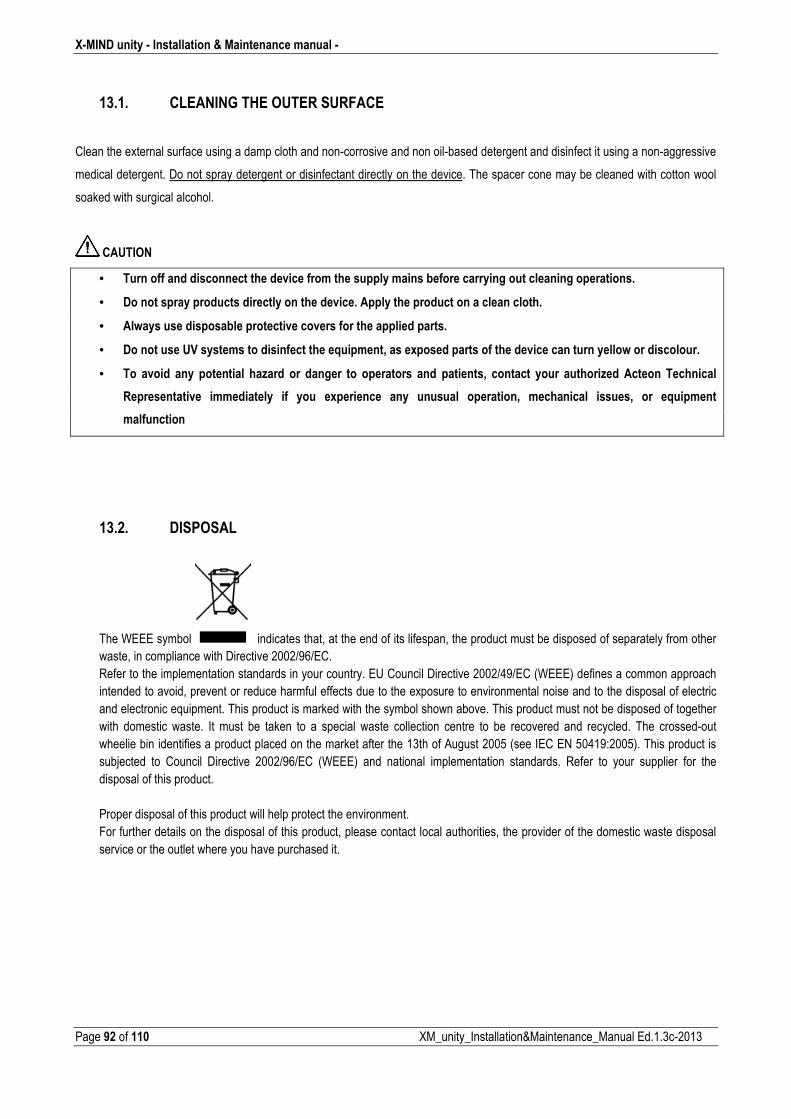
X�MIND unity � Installation & Maintenance manual �
Page 92 of 110 XM_unity_Installation&Maintenance_Manual Ed.1.3c2013
13.1. CLEANING THE OUTER SURFACE
Clean the external surface using a damp cloth and noncorrosive and non oilbased detergent and disinfect it using a nonaggressive
medical detergent. Do not spray detergent or disinfectant directly on the device. The spacer cone may be cleaned with cotton wool
soaked with surgical alcohol.
CAUTION
• Turn off and disconnect the device from the supply mains before carrying out cleaning operations.
• Do not spray products directly on the device. Apply the product on a clean cloth.
• Always use disposable protective covers for the applied parts.
• Do not use UV systems to disinfect the equipment, as exposed parts of the device can turn yellow or discolour.
• To avoid any potential hazard or danger to operators and patients, contact your authorized Acteon Technical
Representative immediately if you experience any unusual operation, mechanical issues, or equipment
malfunction
13.2. DISPOSAL
The WEEE symbol indicates that, at the end of its lifespan, the product must be disposed of separately from other waste, in compliance with Directive 2002/96/EC. Refer to the implementation standards in your country. EU Council Directive 2002/49/EC (WEEE) defines a common approach intended to avoid, prevent or reduce harmful effects due to the exposure to environmental noise and to the disposal of electric and electronic equipment. This product is marked with the symbol shown above. This product must not be disposed of together with domestic waste. It must be taken to a special waste collection centre to be recovered and recycled. The crossedout wheelie bin identifies a product placed on the market after the 13th of August 2005 (see IEC EN 50419:2005). This product is subjected to Council Directive 2002/96/EC (WEEE) and national implementation standards. Refer to your supplier for the disposal of this product. Proper disposal of this product will help protect the environment. For further details on the disposal of this product, please contact local authorities, the provider of the domestic waste disposal service or the outlet where you have purchased it.
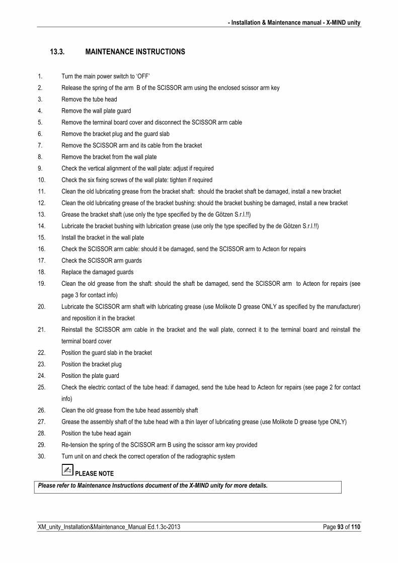
� Installation & Maintenance manual � X�MIND unity
XM_unity_Installation&Maintenance_Manual Ed.1.3c2013 Page 93 of 110
13.3. MAINTENANCE INSTRUCTIONS
1. Turn the main power switch to ‘OFF’
2. Release the spring of the arm B of the SCISSOR arm using the enclosed scissor arm key
3. Remove the tube head
4. Remove the wall plate guard
5. Remove the terminal board cover and disconnect the SCISSOR arm cable
6. Remove the bracket plug and the guard slab
7. Remove the SCISSOR arm and its cable from the bracket
8. Remove the bracket from the wall plate
9. Check the vertical alignment of the wall plate: adjust if required
10. Check the six fixing screws of the wall plate: tighten if required
11. Clean the old lubricating grease from the bracket shaft: should the bracket shaft be damaged, install a new bracket
12. Clean the old lubricating grease of the bracket bushing: should the bracket bushing be damaged, install a new bracket
13. Grease the bracket shaft (use only the type specified by the de Götzen S.r.l.!!)
14. Lubricate the bracket bushing with lubrication grease (use only the type specified by the de Götzen S.r.l.!!)
15. Install the bracket in the wall plate
16. Check the SCISSOR arm cable: should it be damaged, send the SCISSOR arm to Acteon for repairs
17. Check the SCISSOR arm guards
18. Replace the damaged guards
19. Clean the old grease from the shaft: should the shaft be damaged, send the SCISSOR arm to Acteon for repairs (see
page 3 for contact info)
20. Lubricate the SCISSOR arm shaft with lubricating grease (use Molikote D grease ONLY as specified by the manufacturer)
and reposition it in the bracket
21. Reinstall the SCISSOR arm cable in the bracket and the wall plate, connect it to the terminal board and reinstall the
terminal board cover
22. Position the guard slab in the bracket
23. Position the bracket plug
24. Position the plate guard
25. Check the electric contact of the tube head: if damaged, send the tube head to Acteon for repairs (see page 2 for contact
info)
26. Clean the old grease from the tube head assembly shaft
27. Grease the assembly shaft of the tube head with a thin layer of lubricating grease (use Molikote D grease type ONLY)
28. Position the tube head again
29. Retension the spring of the SCISSOR arm B using the scissor arm key provided
30. Turn unit on and check the correct operation of the radiographic system
PLEASE NOTE
$���������������0����������������������������������������9#0��,�������������������������
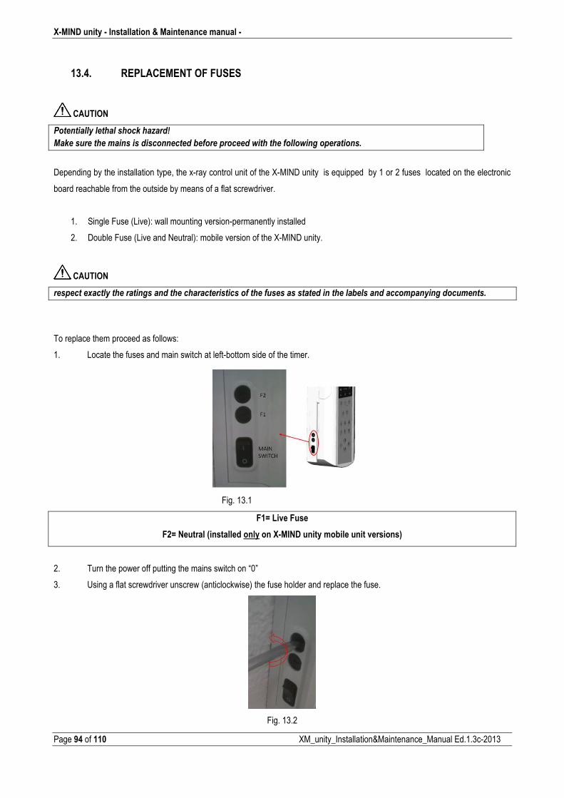
X�MIND unity � Installation & Maintenance manual �
Page 94 of 110 XM_unity_Installation&Maintenance_Manual Ed.1.3c2013
13.4. REPLACEMENT OF FUSES
CAUTION
$����������������������)���E���6�
0�)���������������������������������*���������������������������������������������
Depending by the installation type, the xray control unit of the XMIND unity is equipped by 1 or 2 fuses located on the electronic
board reachable from the outside by means of a flat screwdriver.
1. Single Fuse (Live): wall mounting versionpermanently installed
2. Double Fuse (Live and Neutral): mobile version of the XMIND unity.
CAUTION
���������"��������������������������������������������������������������������������*��������������������������������
To replace them proceed as follows:
1. Locate the fuses and main switch at leftbottom side of the timer.
Fig. 13.1
F1= Live Fuse
F2= Neutral (installed only on X�MIND unity mobile unit versions)
2. Turn the power off putting the mains switch on “0”
3. Using a flat screwdriver unscrew (anticlockwise) the fuse holder and replace the fuse.
Fig. 13.2
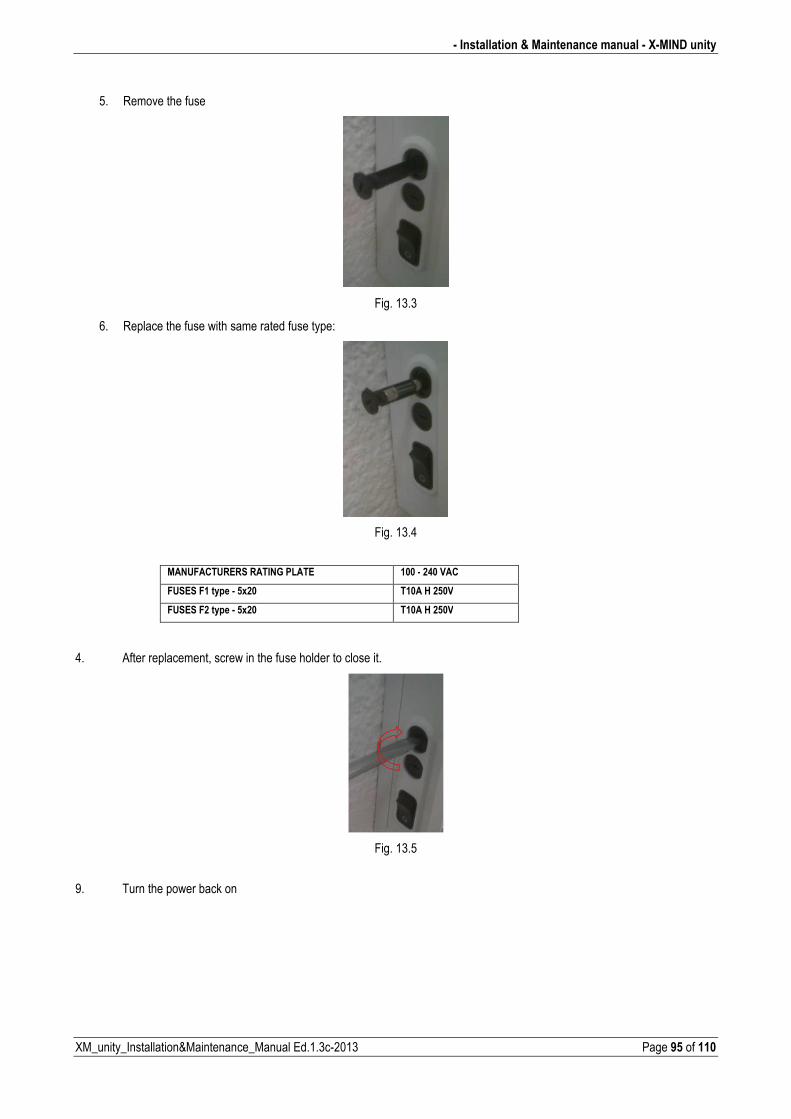
� Installation & Maintenance manual � X�MIND unity
XM_unity_Installation&Maintenance_Manual Ed.1.3c2013 Page 95 of 110
5. Remove the fuse
Fig. 13.3
6. Replace the fuse with same rated fuse type:
Fig. 13.4
MANUFACTURERS RATING PLATE 100 � 240 VAC
FUSES F1 type � 5x20 T10A H 250V
FUSES F2 type � 5x20 T10A H 250V
4. After replacement, screw in the fuse holder to close it.
Fig. 13.5
9. Turn the power back on
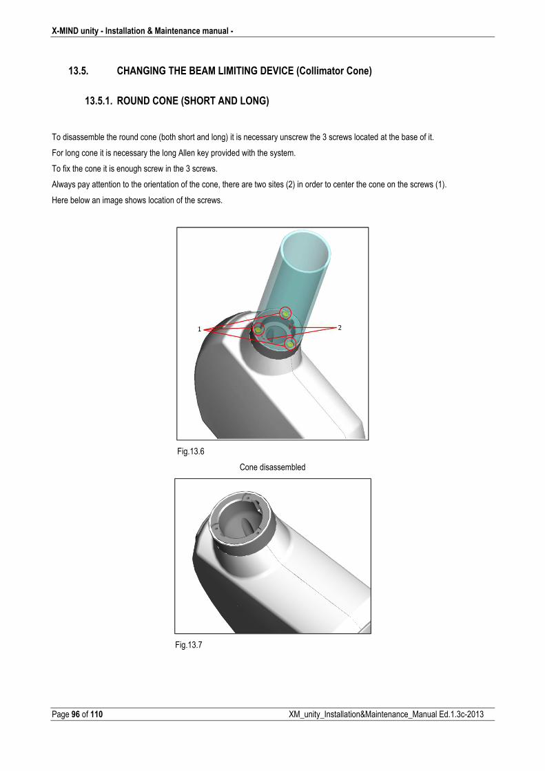
X�MIND unity � Installation & Maintenance manual �
Page 96 of 110 XM_unity_Installation&Maintenance_Manual Ed.1.3c2013
13.5. CHANGING THE BEAM LIMITING DEVICE (Collimator Cone)
13.5.1. ROUND CONE (SHORT AND LONG)
To disassemble the round cone (both short and long) it is necessary unscrew the 3 screws located at the base of it.
For long cone it is necessary the long Allen key provided with the system.
To fix the cone it is enough screw in the 3 screws.
Always pay attention to the orientation of the cone, there are two sites (2) in order to center the cone on the screws (1).
Here below an image shows location of the screws.
Fig.13.6
Cone disassembled
Fig.13.7
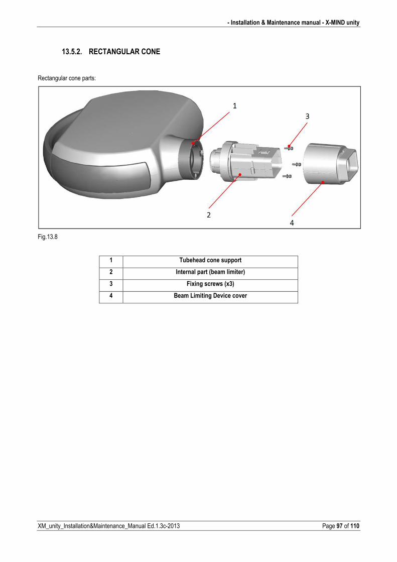
� Installation & Maintenance manual � X�MIND unity
XM_unity_Installation&Maintenance_Manual Ed.1.3c2013 Page 97 of 110
13.5.2. RECTANGULAR CONE
Rectangular cone parts:
Fig.13.8
1 Tubehead cone support
2 Internal part (beam limiter)
3 Fixing screws (x3)
4 Beam Limiting Device cover
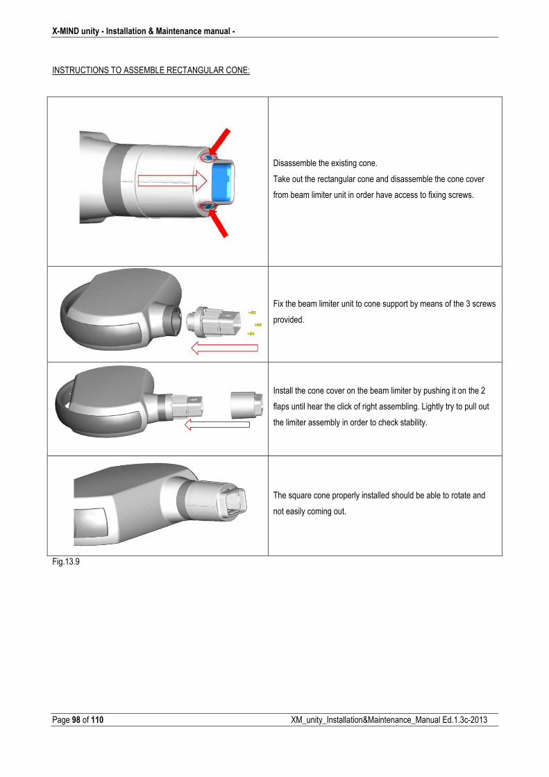
X�MIND unity � Installation & Maintenance manual �
Page 98 of 110 XM_unity_Installation&Maintenance_Manual Ed.1.3c2013
INSTRUCTIONS TO ASSEMBLE RECTANGULAR CONE:
Disassemble the existing cone.
Take out the rectangular cone and disassemble the cone cover
from beam limiter unit in order have access to fixing screws.
Fix the beam limiter unit to cone support by means of the 3 screws
provided.
Install the cone cover on the beam limiter by pushing it on the 2
flaps until hear the click of right assembling. Lightly try to pull out
the limiter assembly in order to check stability.
The square cone properly installed should be able to rotate and
not easily coming out.
Fig.13.9
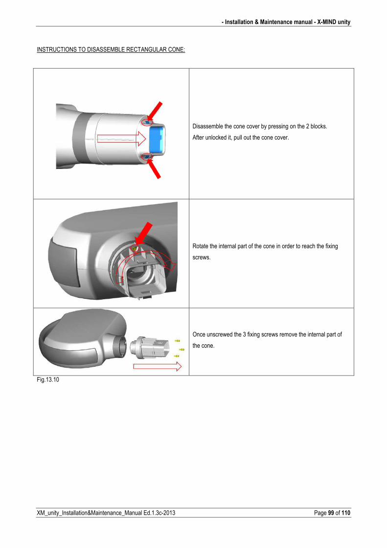
� Installation & Maintenance manual � X�MIND unity
XM_unity_Installation&Maintenance_Manual Ed.1.3c2013 Page 99 of 110
INSTRUCTIONS TO DISASSEMBLE RECTANGULAR CONE:
Disassemble the cone cover by pressing on the 2 blocks.
After unlocked it, pull out the cone cover.
Rotate the internal part of the cone in order to reach the fixing
screws.
Once unscrewed the 3 fixing screws remove the internal part of
the cone.
Fig.13.10
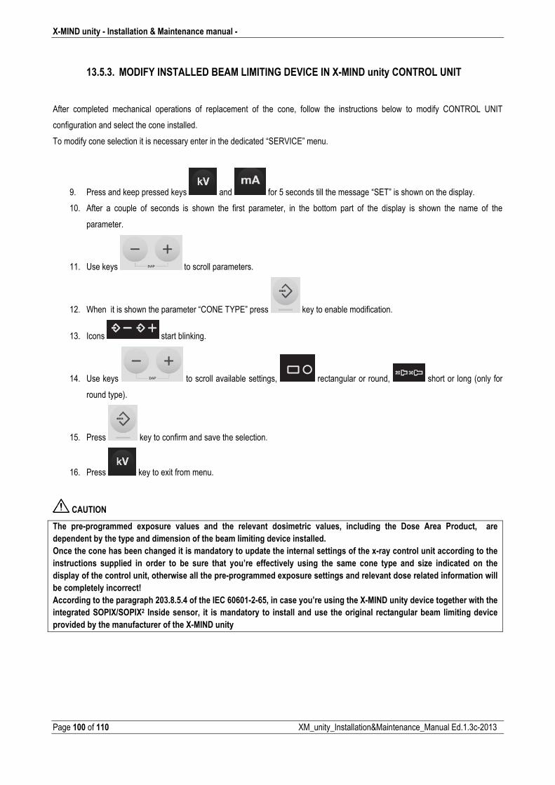
X�MIND unity � Installation & Maintenance manual �
Page 100 of 110 XM_unity_Installation&Maintenance_Manual Ed.1.3c2013
13.5.3. MODIFY INSTALLED BEAM LIMITING DEVICE IN X�MIND unity CONTROL UNIT
After completed mechanical operations of replacement of the cone, follow the instructions below to modify CONTROL UNIT
configuration and select the cone installed.
To modify cone selection it is necessary enter in the dedicated “SERVICE” menu.
9. Press and keep pressed keys and for 5 seconds till the message “SET” is shown on the display.
10. After a couple of seconds is shown the first parameter, in the bottom part of the display is shown the name of the
parameter.
11. Use keys to scroll parameters.
12. When it is shown the parameter “CONE TYPE” press key to enable modification.
13. Icons start blinking.
14. Use keys to scroll available settings, rectangular or round, short or long (only for
round type).
15. Press key to confirm and save the selection.
16. Press key to exit from menu.
CAUTION
The pre�programmed exposure values and the relevant dosimetric values, including the Dose Area Product, are
dependent by the type and dimension of the beam limiting device installed.
Once the cone has been changed it is mandatory to update the internal settings of the x�ray control unit according to the
instructions supplied in order to be sure that you’re effectively using the same cone type and size indicated on the
display of the control unit, otherwise all the pre�programmed exposure settings and relevant dose related information will
be completely incorrect!
According to the paragraph 203.8.5.4 of the IEC 60601�2�65, in case you’re using the X�MIND unity device together with the
integrated SOPIX/SOPIX2 Inside sensor, it is mandatory to install and use the original rectangular beam limiting device
provided by the manufacturer of the X�MIND unity�
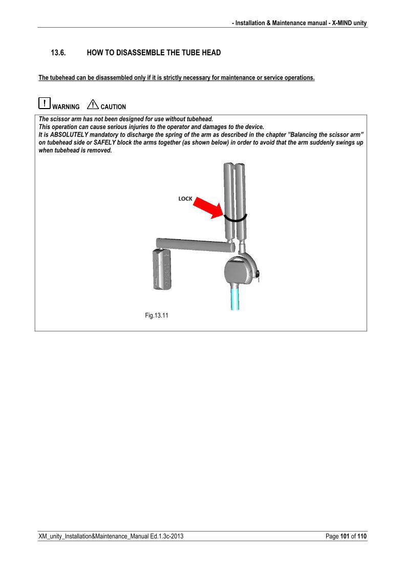
� Installation & Maintenance manual � X�MIND unity
XM_unity_Installation&Maintenance_Manual Ed.1.3c2013 Page 101 of 110
13.6. HOW TO DISASSEMBLE THE TUBE HEAD
The tubehead can be disassembled only if it is strictly necessary for maintenance or service operations.
WARNING CAUTION
������������������������*�������������������������������*��������������������������������������������������������������������������������������(�����������-' %��&%:�������������������������������������������������������*������������������?-������������������������?�������*��������������'4&%:�*���)�������������������1���������*����2��������������(�������������������������������������������*�������������(����
�
� Fig.13.11
�
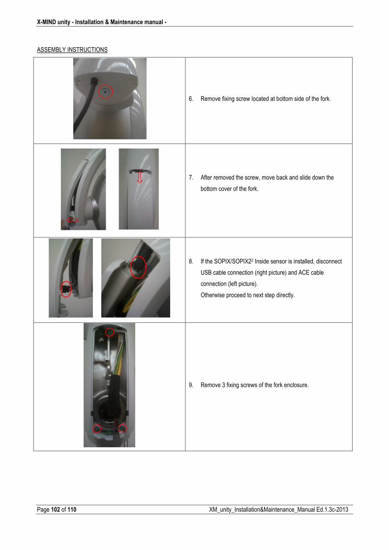
X�MIND unity � Installation & Maintenance manual �
Page 102 of 110 XM_unity_Installation&Maintenance_Manual Ed.1.3c2013
ASSEMBLY INSTRUCTIONS
6. Remove fixing screw located at bottom side of the fork.
7. After removed the screw, move back and slide down the
bottom cover of the fork.
8. If the SOPIX/SOPIX22 Inside sensor is installed, disconnect
USB cable connection (right picture) and ACE cable
connection (left picture).
Otherwise proceed to next step directly.
9. Remove 3 fixing screws of the fork enclosure.
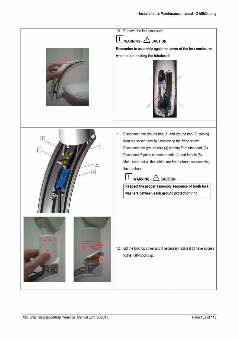
XM_unity_Installation&Maintenance_Manual
� Installation & Maintena
ual Ed.1.3c2013
10. Remove the fork enclosure.
WARNING CAUTION
Remember to assemble again the cov
when re�connecting the tubehead!
11. Disconnect the ground ring (1) and
from the scissor arm by unscrewing
Disconnect the ground wire (3) com
Disconnect 6 poles connector male
Make sure that all the cables are fr
the tubehead.
WARNING CAUTION
Respect the proper assembly s
washers between each ground
12. Lift the fork top cover and if necess
to the halfmoon clip.
enance manual � X�MIND unity
Page 103 of 110
cover of the fork enclosure
and ground ring (2) coming
ing the fixing screw.
coming from tubehead (3).
ale (4) and female (5).
e free before disassembling
ION
y sequence of tooth lock
nd protection ring.
essary rotate it till have access
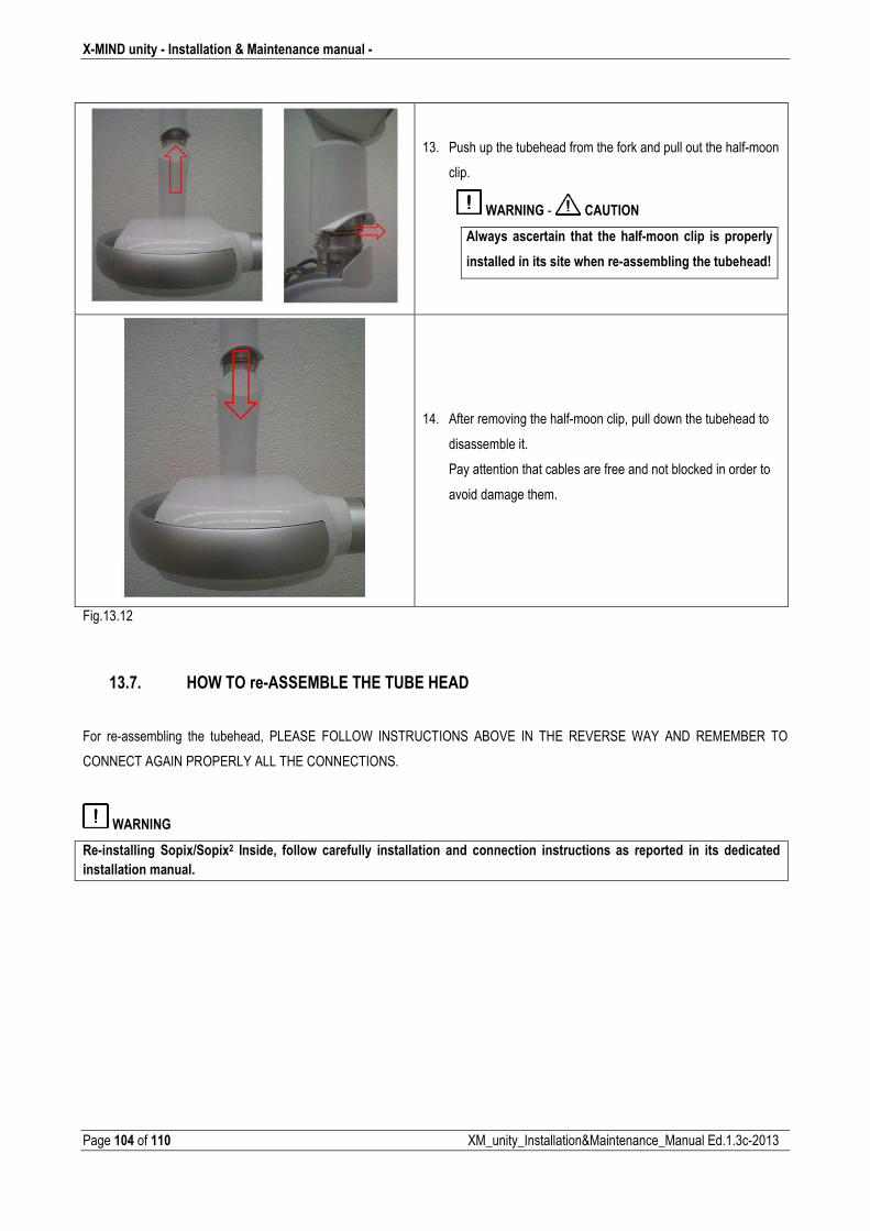
X�MIND unity � Installation & Maintenance manual �
Page 104 of 110 XM_unity_Installation&Maintenance_Manual Ed.1.3c2013
13. Push up the tubehead from the fork and pull out the halfmoon
clip.
WARNING CAUTION
Always ascertain that the half�moon clip is properly
installed in its site when re�assembling the tubehead!
14. After removing the halfmoon clip, pull down the tubehead to
disassemble it.
Pay attention that cables are free and not blocked in order to
avoid damage them.
Fig.13.12
13.7. HOW TO re�ASSEMBLE THE TUBE HEAD
For reassembling the tubehead, PLEASE FOLLOW INSTRUCTIONS ABOVE IN THE REVERSE WAY AND REMEMBER TO
CONNECT AGAIN PROPERLY ALL THE CONNECTIONS.
WARNING
Re�installing Sopix/Sopix2 Inside, follow carefully installation and connection instructions as reported in its dedicated
installation manual.
� Installation & Maintenance manual � X�MIND unity
XM_unity_Installation&Maintenance_Manual Ed.1.3c2013 Page 105 of 110
14. TECHNICAL SPECIFICATIONS
PLEASE NOTE
�����������"��������� ����������0�������������9#0��,�������
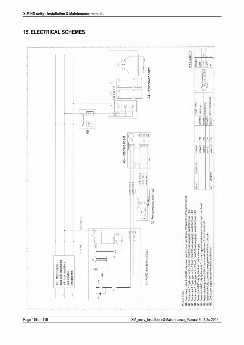
X�MIND unity � Installation & Maintenance manual �
Page 106 of 110 XM_unity_Installation&Maintenance_Manual Ed.1.3c2013
15. ELECTRICAL SCHEMES
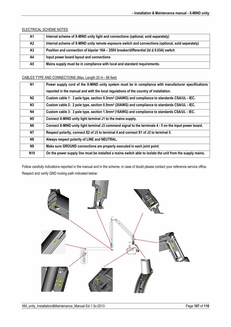
� Installation & Maintenance manual � X�MIND unity
XM_unity_Installation&Maintenance_Manual Ed.1.3c2013 Page 107 of 110
ELECTRICAL SCHEME NOTES
A1 Internal scheme of X�MIND unity light and connections (optional, sold separately)
A2 Internal scheme of X�MIND unity remote exposure switch and connections (optional, sold separately)
A3 Position and connection of bipolar 16A – 250V breaker/differential (Id ≤ 0.03A) switch
A4 Input power board layout and connections
A5 Mains supply must be in compliance with local and standard requirements.
CABLES TYPE AND CONNECTIONS (Max. Length 20 m 66 feet)
N1 Power supply cord of the X�MIND unity system must be in compliance with manufacturer specifications
reported in the manual and with the local regulations of the country of installation.
N2 Custom cable 1: 3 pole type, section 0.3mm2 (24AWG) and compliance to standards CSA/UL � IEC.
N3 Custom cable 2: 2 pole type, section 0.5mm2 (20AWG) and compliance to standards CSA/UL � IEC.
N4 Custom cable 3: 3 pole type, section 1.5mm2 (16AWG) and compliance to standards CSA/UL � IEC.
N5 Connect X�MIND unity light terminal J1 to the mains supply.
N6 Connect X�MIND unity light terminal J3 command signal to the terminals 4 � 5 on the input power board.
N7 Respect polarity, connect S2 of J3 to terminal 4 and connect S1 of J3 to terminal 5.
N8 Always respect polarity of LINE and NEUTRAL.
N9 Make sure GROUND connections are properly executed in each joint point.
N10 On the power supply line must be installed a mains switch able to isolate the unit from the supply mains.
Follow carefully indications reported in the manual and in the scheme, in case of doubt please contact your reference service office.
Respect and verify GND routing path indicated below:
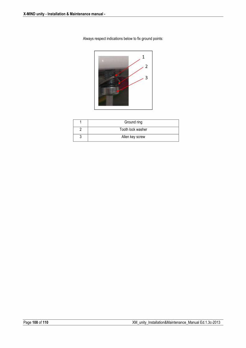
X�MIND unity � Installation & Maintenance manual �
Page 108 of 110 XM_unity_Installation&Maintenance_Manual Ed.1.3c2013
Always respect indications below to fix ground points:
1 Ground ring
2 Tooth lock washer
3 Allen key screw
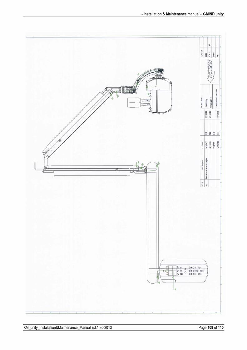
� Installation & Maintenance manual � X�MIND unity
XM_unity_Installation&Maintenance_Manual Ed.1.3c2013 Page 109 of 110
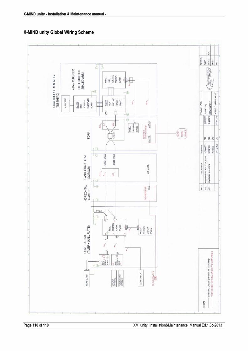
X�MIND unity � Installation & Maintenance manual �
Page 110 of 110 XM_unity_Installation&Maintenance_Manual Ed.1.3c2013
X�MIND unity Global Wiring Scheme