third time’s the charm - rit launch initiative
TRANSCRIPT
Experimental Sounding Rocket Association
1
Third Time’s The Charm
Team 78 Project Technical Report to the 2018 Spaceport America Cup
Z. Rizzolo1 and O. Castillo2
Rochester Institute of Technology, Rochester, NY, 14623
Approved by
Michael Buffalin3
Rochester Institute of Technology, Rochester, NY, 14623
This project involves the design, manufacture, and launch of the RIT Launch Initiative’s
level 3 high-powered rocket, constructed to compete in the 10,000 ft AGL apogee COTS solid
category at the 2018 IREC. This rocket, Third Time’s The Charm (3TTC), is a 10 ft. fiberglass
rocket equipped with a M-2020 75 mm Cesaroni solid motor. The system is designed to
deliver a 3U CubeSat scientific payload at apogee which will descend with an independent
recovery system. The payload, Hyperion, has data acquisition, storage, and real-time
transmission for visualization before, during, and after the launch. Modeling and analysis
were conducted on the entirety of the rocket system. Studies were performed on propulsion,
aerostructures, recovery, avionics, and flight characteristics of the vehicle. A test launch of
this rocket was executed to validate the analysis and overall performance of the vehicle prior
to the 2018 IREC. Current models suggest that 3TTC will reach an altitude of 10,227 feet.
Nomenclature
Fd = Drag Force
W = Weight of Rocket
m = Mass of Rocket
a = Acceleration
Cd = Drag Coefficient
ρ = Free Stream Density of Air
A = Projected Parachute Area
g = Gravity
F = Force
SA = Surface Area
σ = Normal Stress
Xs = Normal Stress Factor of Safety
σyield = Normal Yield Stress
σring = Normal Stress on Ring
σultimate = Ultimate Strength
τ = Shear Stress
τedge = Shear Stress on Inner Edge
τbodytube = Shear Stress of Body Tube
τepoxy = Shear Stress of Epoxy
Ys = Shear Stress Factor of Safety
Es = Epoxy Factor of Safety
Bs = Body Tube Factor of Safety
Sstrength = Shear Strength
1 Master’s Student, Department of Mechanical Engineering, 1 Lomb Memorial Dr., Rochester, NY 14623. 2 Master’s Student, Department of Mechanical Engineering, 1 Lomb Memorial Dr., Rochester, NY 14623. 3 Club Advisor, Department of Innovation and Entrepreneurship, 1 Lomb Memorial Dr., Rochester, NY 14623.
Experimental Sounding Rocket Association
2
mpayload = Mass of Payload
Apayload = Payload Projected Area
t = Time
vterminal = Terminal Velocity
I. Introduction
HE RIT Launch Initiative is a multidisciplinary student organization that applies the principles of rocket design
and manufacturing for learning and competition. The team aims to prepare students for excellence in aerospace,
to conduct novel research and development, and put RIT at the forefront of the emerging space push. This year the
team has expanded by 50% and made great strides towards becoming a leading competition team in the college of
engineering here at RIT. The team has successfully flown two L3 rockets, one L2 rocket, and has certified 25
members to fly L1 rockets under the National Association of Rocketry (NAR). Additionally, several team members
hold individual L2 high-powered rocketry NAR certifications.
RIT LI is comprised of 2 major teams – mechanical and avionics. The Mechanical Team is headed by the Lead
Mechanical Engineer (LME). The Structures Lead Engineer (SLE) and Aerodynamics Lead Engineer (ALE) report
directly to the LME. The Chief Booster Engineer and Chief Payload Engineer then report to the SLE, while the ALE
does not have any direct reports. All other engineers are known as “Responsible Engineers” and are assigned based
on skillset and interest. In addition, all members have the option to contribute to research and development (R&D)
projects that push the team to create new rocket technologies. The Avionics Team is divided into a Hardware Team
and Software Team, each with a team lead. All other avionics members fall into one of these two groups. As the
organization continues to expand, team management strategies are continuously being molded around the personnel,
resources, and team goals for any given year.
This will be the team’s first year attending the IREC. We will be competing in the “10,000 ft AGL apogee with
commercial-off-the-shelf (COTS) solid or hybrid rocket propulsion system” category. The rocket that will be flying
has a solid propulsion system, great structural integrity, and has previously been test launched to 10,909 feet at a
launch site in Potter, New York. This all fiberglass rocket encompasses a design that has stemmed from 3 years of
rocket architecture, analysis, and building, as well as the lessons learned along the way. Several team members have
held internships at SpaceX, Blue Origin, NASA, among others, and have been able to integrate valuable knowledge
into this team and its designs. In conjunction with this year’s IREC efforts, our team is conducting R&D projects
that include custom filament wound carbon fiber body tubes, mechanical separation mechanisms, and a 1300 lb.
thrust hybrid rocket engine. The team plans to introduce these designs at the next IREC competition.
II. System Architecture Review
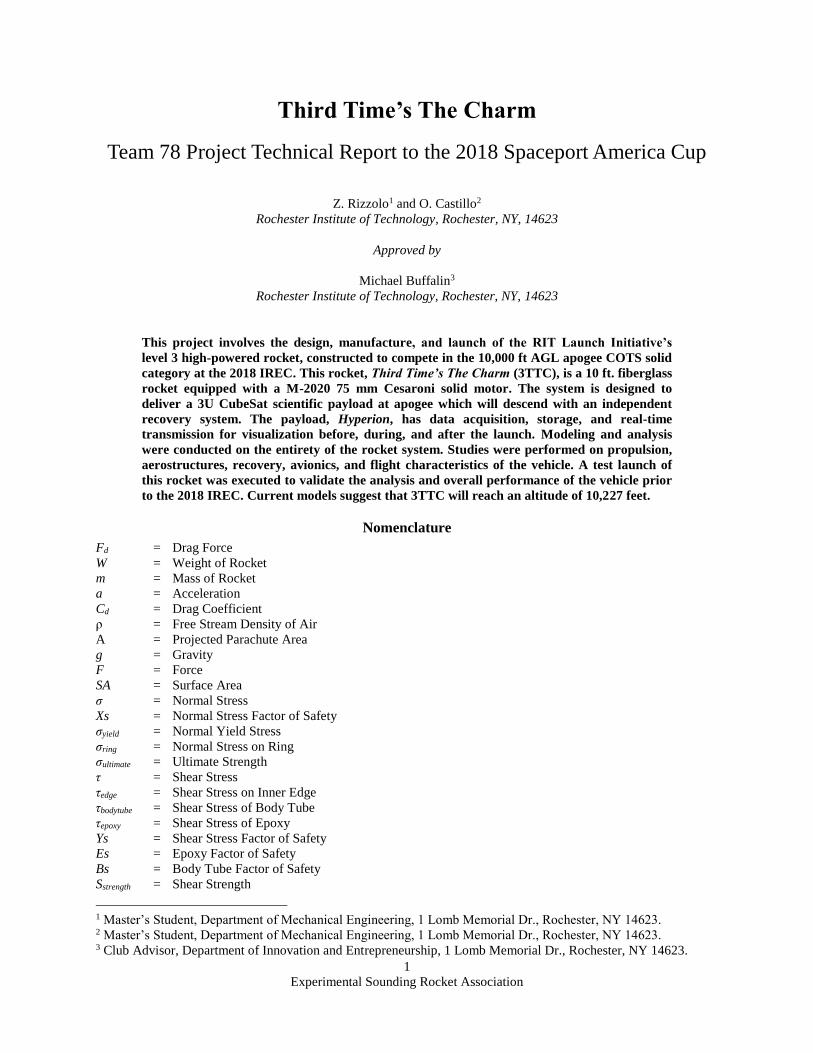
Third Time’s The Charm is a 10.5-foot-tall level 3 high-powered rocket. The rocket body is entirely G10
fiberglass and is broken up into 5 sections. The sections include the booster, payload bay, avionics bay, main
parachute bay, and nosecone. The booster holds the M-2020 Cesaroni 6 grain motor, and transfers the thrust through
the custom force plate into the airframe. The force plate was designed to be the only structural bulkhead in the
system, simplifying the structural design requirements and analysis upstream. The rocket encompasses a dual-deploy
recovery system, utilizing black powder to provide separation forces. A 5-foot drogue parachute and 14-foot main
parachute will be deployed from the payload bay and main parachute bay, respectively. The combined effort will
allow the rocket to descend safely to earth, yet still land within a reasonable distance from the launch pad.
The payload of this rocket is a scientific 3U CubeSat that has real-time data acquisition, storage, and
transmission for visualization before, during, and after the launch. It is complete with an independent recovery
system that will guide it safely to the ground after ejection at apogee, with the help of a custom sabot design. The
electronics on-board are all housed on the avionics sled, within the avionics bay. This system includes a telemetry
flight computer, stratologger, eggtimer quark, GPS, omnidirectional antenna, magnetometer, accelerometer,
gyroscope, and 3 power supplies. Lastly, the nosecone is a 5:1 tangent ogive made of fiberglass with an aluminum
tip. A custom shoulder was made for the metal tip that supports a threaded rod concentrically running the length of
the structure. This threaded rod not only transfers the load of the main parachute shock force, but also allows for
ballasts to be easily integrated inside the nosecone if necessary for stability.
T
Experimental Sounding Rocket Association
3
A. Propulsion Subsystems
The propulsion system of this rocket encompasses a commercial off the shelf (COTS) solid rocket motor. The
motor is an M-class 75mm six grain Cesaroni M2020. The fuel grains are IMAX and have the highest impulse
density of all commercial motors of this class. Moreover, the grains are housed in a commercial phenolic liner which
is located inside a second generation 75mm P75-6G Cesaroni motor casing. The motor delivers a total impulse of
1895 lb-s and peak thrust of 602.6 lb. It will burn for 4.17 seconds with a specific impulse of 197.6 seconds. The motor was chosen as one of the last steps in the design process of the rocket. After all major subsystems
were designed and the weights of their respective components were taken into consideration, an open rocket model
was created. This model allowed us to assess the effects of different motors on the flight characteristics and target
altitude of the rocket. Having previous experience with level 3 rockets, it was decided to start with an M-class
motor. RIT LI already owns a 75 mm motor casing and therefore the diameter of the motor was chosen to be this
size for cost savings. Because the weight of the rocket was expected to be over 50 lb. with the payload, a 6-grain
motor was required to reach 10,000 feet. Simultaneously, aerodynamic parameters such as fin dimensions were
iterated with potential motor options to assess the rocket’s ability to reach 10,000 feet, while maintaining the
stability margins required by IREC.
The motor is equipped with a phenolic liner, 6 fuel grains, ceramic nozzle attachment, nozzle holder, 3 nozzle
orings, 2 retention rings, forward insulating disk, forward closure, tracking smoke element, tracking smoke
insulator, spacer, 5 grain-spacing orings, and an igniter. The spacer is not used in this motor because 6 grains fill up
the volumetric capacity within the liner. The exterior of the phenolic liner is coated with a thin layer of lithium
grease before being inserted into the casing. This is done not only for ease of assembly, but also as a safety
precaution because the grease acts as a seal and minimizes the potential for leaking combustion gases. After the motor is assembled and both end caps are screwed in, the gap between the aft retention ring and the end
of the motor casing is assessed. This gap is usually very small but nonetheless it recesses the aft retention ring from
the end of the casing, a common occurrence for Cesaroni motors. In this instance, acrylic spacer rings are added as
needed such that upon inserting the motor assembly into the motor mount tube, the casing will mate flush with the
booster force plate. The acrylic rings are also necessary because the motor cannot slide fully into the booster and be
rigidly retained from the forward closure at the top of the booster. The reason for this is that the dimensions of the
motor casing cannot be changed, and the booster airframe only came in 30-inch sections. After assembly, it was
found that the motor casing is marginally bigger than the motor mount tube. The motor would work without the
acrylic spacers, but in the interest of fully constraining the system, they will be used as needed. The motor is then
retained from the top of the booster through the forward closure. An eye-nut and threaded rod are threaded into the
forward closure through a small opening at the top of the booster. This puts the forward closure and motor casing in
Figure 1: Rocket System Schematic
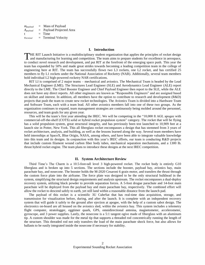
Figure 2: Rocket System CAD Model
Experimental Sounding Rocket Association
4
tension, thus retaining the motor inside the motor mount tube. See figure 13 in Appendix A for motor components
and see figure 32 in Appendix B for the motor thrust curve.
B. Aerostructures Subsystems
A rocket is defined by its structure and shape. The shape of the rocket is critical in achieving the most
aerodynamic vehicle. The structure of the rocket must be designed to sustain all loads the vehicle experiences during
operation to guarantee a successful mission. The structural elements of this rocket are the booster, upper stage,
nosecone, and fins.
The booster houses the engine or motor of the rocket. It is responsible for transferring the developed thrust from
the motor into the rocket structure and fixing the engine in place. For 3TTC, the load is transferred from the motor
into an aluminum force plate. The force plate then transfers the thrust force into the airframe. The airframe material
is G12 fiberglass tube that is 6 inches in diameter and 30 inches long for the booster section. Four 1/8” slots were cut
into the bottom of the booster tube for fin placement. These slots are 5 inches long and 1.5 inches from the bottom
of the booster tube, corresponding with the designed fin tabs. The fins were placed in between the centering rings to
provide further structural integrity and proper fin alignment. The last centering ring was placed further up in the
booster to provide proper alignment of the cardboard motor tube. The motor tube allows for the motor to be easily
integrated axially into the booster.
The force plate is responsible for transferring all developed thrust by constraining the motor in the thrust vector
direction. A lip was designed on the outer edge of the force plate such that it can transfer force directly to the bottom
of the booster, as well as through the sides where it is epoxied to the airframe. The force plate is made from 0.5”
thick 6061 aluminum plate. Aluminum was chosen for its availability, strength, and ease of machining. Please
reference Drawing 9 in Appendix G for more on the force plate. With a maximum motor load of 603lbs, stress
calculations were used to determine the thickness of the force plate. The equations used are below.
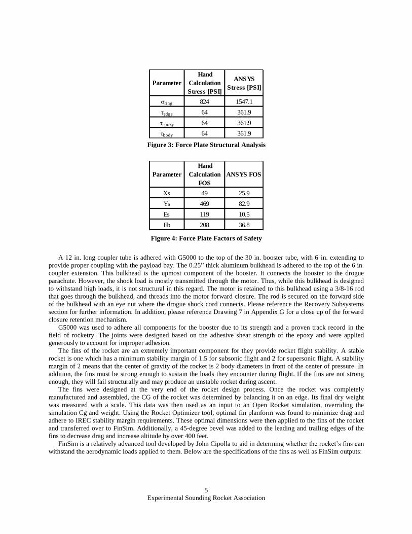
An ANSYS model was developed to validate the force plate would not fail under expected loads. The localized
Von Mises stresses were determined using a static structural analysis. The geometry of the retention ring from the
motor casing was projected onto the bottom side of the force plate. The maximum thrust load was applied. The outer
perimeter was treated as a bonded fixed support. An additional frictional contact was applied to the retention ring
projected area.
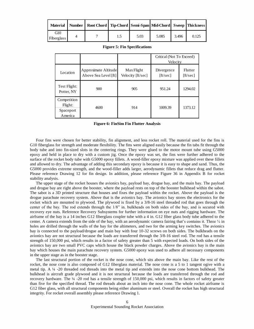
The analysis revealed an extremely high factor of safety for Aluminum T6 6061. All calculations yielded
acceptable FOS with enough margin to account for discontinuities or improper adhesion of the G5000 High Strength
Epoxy. The results are summarized in Figure 3 and 4 below.
Experimental Sounding Rocket Association
5
Parameter
Hand
Calculation
Stress [PSI]
ANSYS
Stress [PSI]
σring 824 1547.1
τedge 64 361.9
τepoxy 64 361.9
τbody 64 361.9
Parameter
Hand
Calculation
FOS
ANSYS FOS
Xs 49 25.9
Ys 469 82.9
Es 119 10.5
Eb 208 36.8
A 12 in. long coupler tube is adhered with G5000 to the top of the 30 in. booster tube, with 6 in. extending to
provide proper coupling with the payload bay. The 0.25” thick aluminum bulkhead is adhered to the top of the 6 in.
coupler extension. This bulkhead is the upmost component of the booster. It connects the booster to the drogue
parachute. However, the shock load is mostly transmitted through the motor. Thus, while this bulkhead is designed
to withstand high loads, it is not structural in this regard. The motor is retained to this bulkhead using a 3/8-16 rod
that goes through the bulkhead, and threads into the motor forward closure. The rod is secured on the forward side
of the bulkhead with an eye nut where the drogue shock cord connects. Please reference the Recovery Subsystems
section for further information. In addition, please reference Drawing 7 in Appendix G for a close up of the forward
closure retention mechanism.
G5000 was used to adhere all components for the booster due to its strength and a proven track record in the
field of rocketry. The joints were designed based on the adhesive shear strength of the epoxy and were applied
generously to account for improper adhesion.
The fins of the rocket are an extremely important component for they provide rocket flight stability. A stable
rocket is one which has a minimum stability margin of 1.5 for subsonic flight and 2 for supersonic flight. A stability
margin of 2 means that the center of gravity of the rocket is 2 body diameters in front of the center of pressure. In
addition, the fins must be strong enough to sustain the loads they encounter during flight. If the fins are not strong
enough, they will fail structurally and may produce an unstable rocket during ascent.
The fins were designed at the very end of the rocket design process. Once the rocket was completely
manufactured and assembled, the CG of the rocket was determined by balancing it on an edge. Its final dry weight
was measured with a scale. This data was then used as an input to an Open Rocket simulation, overriding the
simulation Cg and weight. Using the Rocket Optimizer tool, optimal fin planform was found to minimize drag and
adhere to IREC stability margin requirements. These optimal dimensions were then applied to the fins of the rocket
and transferred over to FinSim. Additionally, a 45-degree bevel was added to the leading and trailing edges of the
fins to decrease drag and increase altitude by over 400 feet.
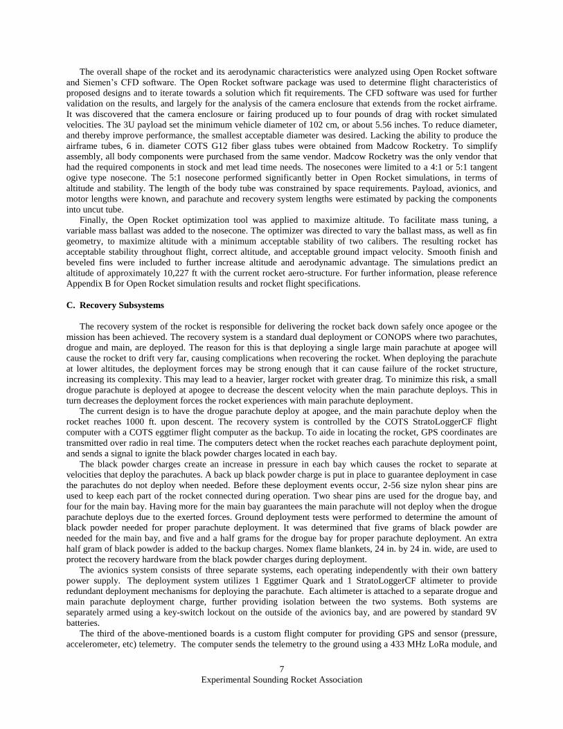
FinSim is a relatively advanced tool developed by John Cipolla to aid in determing whether the rocket’s fins can
withstand the aerodynamic loads applied to them. Below are the specifications of the fins as well as FinSim outputs:
Figure 3: Force Plate Structural Analysis
Figure 4: Force Plate Factors of Safety
Experimental Sounding Rocket Association
6
Material Number Root Chord Tip-Chord Semi-Span Mid-Chord Sweep Thickness
G10
Fiberglass4 7 1.5 5.03 5.085 3.496 0.125
LocationApproximate Altitude
Above Sea Level [ft]
Max Flight
Velocity [ft/sec]
Divergence
[ft/sec]
Flutter
[ft/sec]
Test Flight:
Potter, NY900 905 951.24 1294.02
Competition
Flight:
Spaceport
America
Critical (Not To Exceed)
Velocity
4600 914 1009.39 1373.12
Four fins were chosen for better stability, fin alignment, and less rocket roll. The material used for the fins is
G10 fiberglass for strength and moderate flexibility. The fins were aligned easily because the fin tabs fit through the
body tube and into fin-sized slots in the centering rings. They were glued to the motor mount tube using G5000
epoxy and held in place to dry with a custom jig. Once the epoxy was set, the fins were further adhered to the
surface of the rocket body tube with G5000 epoxy fillets. A wood-filler epoxy mixture was applied over these fillets
and allowed to dry. The advantage of adding this secondary epoxy is because it is easy to shape and sand. Thus, the
G5000 provides extreme strength, and the wood-filler adds larger, aerodynamic fillets that reduce drag and flutter.
Please reference Drawing 12 for fin design. In addition, please reference Figure 36 in Appendix B for rocket
stability analysis.
The upper stage of the rocket houses the avionics bay, payload bay, drogue bay, and the main bay. The payload
and drogue bay are right above the booster, where the payload rests on top of the booster bulkhead within the sabot.
The sabot is a 3D printed structure that houses and fixes the payload within the rocket. Above the payload is the
drogue parachute recovery system. Above that is the avionics bay. The avionics bay stores the electronics for the
rocket which are mounted to plywood. The plywood is fixed by a 3/8-16 steel threaded rod that goes through the
center of the bay. The rod extends through the 1/8” in. bulkheads on both sides of the bay, and is secured with
recovery eye nuts. Reference Recovery Subsystems for further information on eye nuts and rigging hardware. The
airframe of the bay is a 14 inches G12 fiberglass coupler tube with a 4 in. G12 fiber glass body tube adhered to the
center. A camera extends from the side of the bay, with an aerodynamic camera fairing that’s contains it. Three ¼ in
holes are drilled through the walls of the bay for the altimeters, and two for the arming key switches. The avionics
bay is connected to the payload/drogue and main bay with four 10-32 screws on both sides. The bulkheads on the
avionics bay are not structural because the loads are transferred through the 3/8-16 steel rod. The rod has a tensile
strength of 150,000 psi, which results in a factor of safety greater than 5 with expected loads. On both sides of the
avionics bay are two small PVC caps which house the black powder charges. Above the avionics bay is the main
bay which houses the main parachute recovery system. G5000 epoxy was used to adhere all necessary components
in the upper stage as in the booster stage.
The last structural portion of the rocket is the nose cone, which sits above the main bay. Like the rest of the
rocket, the nose cone is also composed of G12 fiberglass material. The nose cone is a 5 to 1 tangent ogive with a
metal tip. A ¼ -20 threaded rod threads into the metal tip and extends into the nose cone bottom bulkhead. The
bulkhead is aircraft grade plywood and it is not structural because the loads are transferred through the rod and
recovery hardware. The ¼ -20 rod has a tensile strength of 150,000 psi, which results in factors of safety greater
than five for the specified thread. The rod threads about an inch into the nose cone. The whole rocket airframe is
G12 fiber glass, with all structural components being either aluminum or steel. Overall the rocket has high structural
integrity. For rocket overall assembly please reference Drawing 1.
Figure 5: Fin Specifications
Figure 6: FinSim Fin Flutter Analysis
Experimental Sounding Rocket Association
7
The overall shape of the rocket and its aerodynamic characteristics were analyzed using Open Rocket software
and Siemen’s CFD software. The Open Rocket software package was used to determine flight characteristics of
proposed designs and to iterate towards a solution which fit requirements. The CFD software was used for further
validation on the results, and largely for the analysis of the camera enclosure that extends from the rocket airframe.
It was discovered that the camera enclosure or fairing produced up to four pounds of drag with rocket simulated
velocities. The 3U payload set the minimum vehicle diameter of 102 cm, or about 5.56 inches. To reduce diameter,
and thereby improve performance, the smallest acceptable diameter was desired. Lacking the ability to produce the
airframe tubes, 6 in. diameter COTS G12 fiber glass tubes were obtained from Madcow Rocketry. To simplify
assembly, all body components were purchased from the same vendor. Madcow Rocketry was the only vendor that
had the required components in stock and met lead time needs. The nosecones were limited to a 4:1 or 5:1 tangent
ogive type nosecone. The 5:1 nosecone performed significantly better in Open Rocket simulations, in terms of
altitude and stability. The length of the body tube was constrained by space requirements. Payload, avionics, and
motor lengths were known, and parachute and recovery system lengths were estimated by packing the components
into uncut tube.
Finally, the Open Rocket optimization tool was applied to maximize altitude. To facilitate mass tuning, a
variable mass ballast was added to the nosecone. The optimizer was directed to vary the ballast mass, as well as fin
geometry, to maximize altitude with a minimum acceptable stability of two calibers. The resulting rocket has
acceptable stability throughout flight, correct altitude, and acceptable ground impact velocity. Smooth finish and
beveled fins were included to further increase altitude and aerodynamic advantage. The simulations predict an
altitude of approximately 10,227 ft with the current rocket aero-structure. For further information, please reference
Appendix B for Open Rocket simulation results and rocket flight specifications.
C. Recovery Subsystems
The recovery system of the rocket is responsible for delivering the rocket back down safely once apogee or the
mission has been achieved. The recovery system is a standard dual deployment or CONOPS where two parachutes,
drogue and main, are deployed. The reason for this is that deploying a single large main parachute at apogee will
cause the rocket to drift very far, causing complications when recovering the rocket. When deploying the parachute
at lower altitudes, the deployment forces may be strong enough that it can cause failure of the rocket structure,
increasing its complexity. This may lead to a heavier, larger rocket with greater drag. To minimize this risk, a small
drogue parachute is deployed at apogee to decrease the descent velocity when the main parachute deploys. This in
turn decreases the deployment forces the rocket experiences with main parachute deployment.
The current design is to have the drogue parachute deploy at apogee, and the main parachute deploy when the
rocket reaches 1000 ft. upon descent. The recovery system is controlled by the COTS StratoLoggerCF flight
computer with a COTS eggtimer flight computer as the backup. To aide in locating the rocket, GPS coordinates are
transmitted over radio in real time. The computers detect when the rocket reaches each parachute deployment point,
and sends a signal to ignite the black powder charges located in each bay. The black powder charges create an increase in pressure in each bay which causes the rocket to separate at
velocities that deploy the parachutes. A back up black powder charge is put in place to guarantee deployment in case
the parachutes do not deploy when needed. Before these deployment events occur, 2-56 size nylon shear pins are
used to keep each part of the rocket connected during operation. Two shear pins are used for the drogue bay, and
four for the main bay. Having more for the main bay guarantees the main parachute will not deploy when the drogue
parachute deploys due to the exerted forces. Ground deployment tests were performed to determine the amount of
black powder needed for proper parachute deployment. It was determined that five grams of black powder are
needed for the main bay, and five and a half grams for the drogue bay for proper parachute deployment. An extra
half gram of black powder is added to the backup charges. Nomex flame blankets, 24 in. by 24 in. wide, are used to
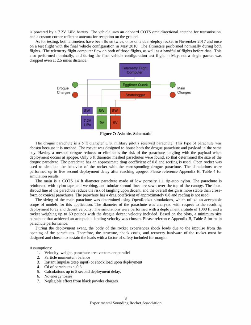
protect the recovery hardware from the black powder charges during deployment. The avionics system consists of three separate systems, each operating independently with their own battery
power supply. The deployment system utilizes 1 Eggtimer Quark and 1 StratoLoggerCF altimeter to provide
redundant deployment mechanisms for deploying the parachute. Each altimeter is attached to a separate drogue and
main parachute deployment charge, further providing isolation between the two systems. Both systems are
separately armed using a key-switch lockout on the outside of the avionics bay, and are powered by standard 9V
batteries.
The third of the above-mentioned boards is a custom flight computer for providing GPS and sensor (pressure,
accelerometer, etc) telemetry. The computer sends the telemetry to the ground using a 433 MHz LoRa module, and
Experimental Sounding Rocket Association
8
is powered by a 7.2V LiPo battery. The vehicle uses an onboard COTS omnidirectional antenna for transmission,
and a custom corner-reflector antenna for reception on the ground. As for testing, both altimeters have been flown twice, once on a dual-deploy rocket in November 2017 and once
on a test flight with the final vehicle configuration in May 2018. The altimeters performed nominally during both
flights. The telemetry flight computer flew on both of those flights, as well as a handful of flights before that. This
also performed nominally, and during the final vehicle configuration test flight in May, not a single packet was
dropped even at 2.5 miles distance.
Figure 7: Avionics Schematic
The drogue parachute is a 5 ft diameter U.S. military pilot’s reserved parachute. This type of parachute was
chosen because it is meshed. The rocket was designed to house both the drogue parachute and payload in the same
bay. Having a meshed drogue reduces or eliminates the risk of the parachute tangling with the payload when
deployment occurs at apogee. Only 5 ft diameter meshed parachutes were found, so that determined the size of the
drogue parachute. The parachute has an approximate drag coefficient of 0.8 and reefing is used. Open rocket was
used to simulate the behavior of the rocket with the corresponding drogue parachute. The simulations were
performed up to five second deployment delay after reaching apogee. Please reference Appendix B, Table 4 for
simulation results. The main is a COTS 14 ft diameter parachute made of low porosity 1.1 rip-stop nylon. The parachute is
reinforced with nylon tape and webbing, and tubular shroud lines are sewn over the top of the canopy. The four-
shroud line of the parachute reduce the risk of tangling upon decent, and the overall design is more stable than cross-
form or conical parachutes. The parachute has a drag coefficient of approximately 0.8 and reefing is not used. The sizing of the main parachute was determined using OpenRocket simulations, which utilize an acceptable
scope of models for this application. The diameter of the parachute was analyzed with respect to the resulting
deployment force and decent velocity. The simulations were performed with a deployment altitude of 1000 ft. and a
rocket weighing up to 60 pounds with the drogue decent velocity included. Based on the plots, a minimum size
parachute that achieved an acceptable landing velocity was chosen. Please reference Appendix B, Table 5 for main
parachute performance.
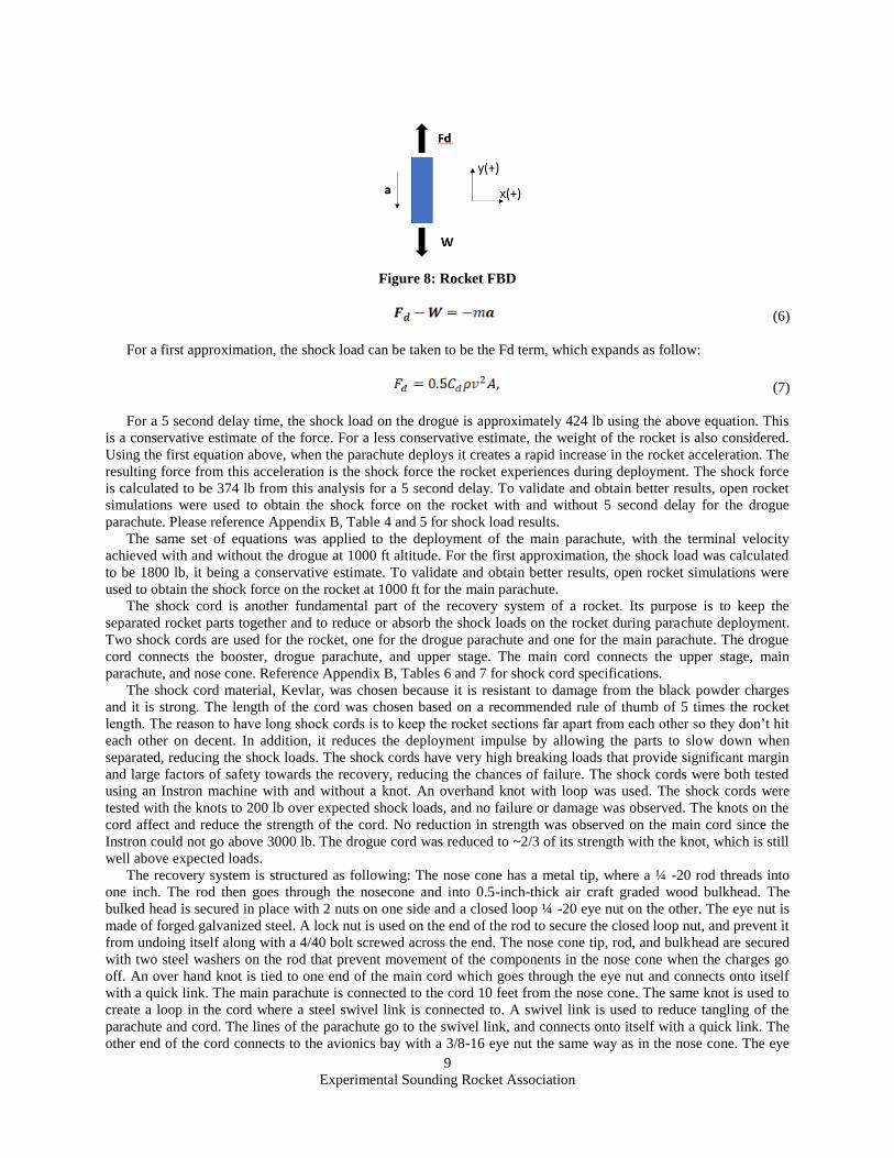
During the deployment event, the body of the rocket experiences shock loads due to the impulse from the
opening of the parachutes. Therefore, the structure, shock cords, and recovery hardware of the rocket must be
designed and chosen to sustain the loads with a factor of safety included for margin. Assumptions:
1. Velocity, weight, parachute area vectors are parallel
2. Particle momentum balance
3. Instant Impulse (step input) or shock load upon deployment
4. Cd of parachutes ~ 0.8
5. Calculations up to 5 second deployment delay.
6. No energy losses
7. Negligible effect from black powder charges
Experimental Sounding Rocket Association
9
Figure 8: Rocket FBD
(6)
For a first approximation, the shock load can be taken to be the Fd term, which expands as follow:
(7)
For a 5 second delay time, the shock load on the drogue is approximately 424 lb using the above equation. This
is a conservative estimate of the force. For a less conservative estimate, the weight of the rocket is also considered.
Using the first equation above, when the parachute deploys it creates a rapid increase in the rocket acceleration. The
resulting force from this acceleration is the shock force the rocket experiences during deployment. The shock force
is calculated to be 374 lb from this analysis for a 5 second delay. To validate and obtain better results, open rocket
simulations were used to obtain the shock force on the rocket with and without 5 second delay for the drogue
parachute. Please reference Appendix B, Table 4 and 5 for shock load results.
The same set of equations was applied to the deployment of the main parachute, with the terminal velocity
achieved with and without the drogue at 1000 ft altitude. For the first approximation, the shock load was calculated
to be 1800 lb, it being a conservative estimate. To validate and obtain better results, open rocket simulations were
used to obtain the shock force on the rocket at 1000 ft for the main parachute.
The shock cord is another fundamental part of the recovery system of a rocket. Its purpose is to keep the
separated rocket parts together and to reduce or absorb the shock loads on the rocket during parachute deployment.
Two shock cords are used for the rocket, one for the drogue parachute and one for the main parachute. The drogue
cord connects the booster, drogue parachute, and upper stage. The main cord connects the upper stage, main
parachute, and nose cone. Reference Appendix B, Tables 6 and 7 for shock cord specifications.
The shock cord material, Kevlar, was chosen because it is resistant to damage from the black powder charges
and it is strong. The length of the cord was chosen based on a recommended rule of thumb of 5 times the rocket
length. The reason to have long shock cords is to keep the rocket sections far apart from each other so they don’t hit
each other on decent. In addition, it reduces the deployment impulse by allowing the parts to slow down when
separated, reducing the shock loads. The shock cords have very high breaking loads that provide significant margin
and large factors of safety towards the recovery, reducing the chances of failure. The shock cords were both tested
using an Instron machine with and without a knot. An overhand knot with loop was used. The shock cords were
tested with the knots to 200 lb over expected shock loads, and no failure or damage was observed. The knots on the
cord affect and reduce the strength of the cord. No reduction in strength was observed on the main cord since the
Instron could not go above 3000 lb. The drogue cord was reduced to ~2/3 of its strength with the knot, which is still
well above expected loads.
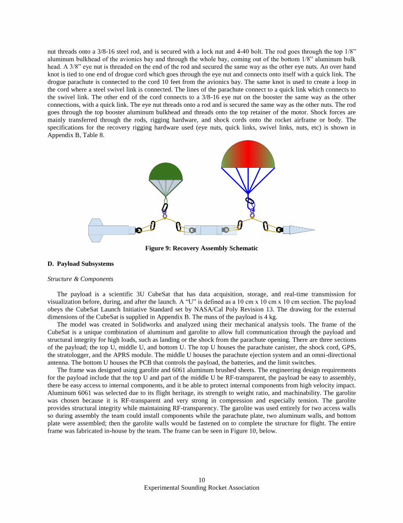
The recovery system is structured as following: The nose cone has a metal tip, where a ¼ -20 rod threads into
one inch. The rod then goes through the nosecone and into 0.5-inch-thick air craft graded wood bulkhead. The
bulked head is secured in place with 2 nuts on one side and a closed loop ¼ -20 eye nut on the other. The eye nut is
made of forged galvanized steel. A lock nut is used on the end of the rod to secure the closed loop nut, and prevent it
from undoing itself along with a 4/40 bolt screwed across the end. The nose cone tip, rod, and bulkhead are secured
with two steel washers on the rod that prevent movement of the components in the nose cone when the charges go
off. An over hand knot is tied to one end of the main cord which goes through the eye nut and connects onto itself
with a quick link. The main parachute is connected to the cord 10 feet from the nose cone. The same knot is used to
create a loop in the cord where a steel swivel link is connected to. A swivel link is used to reduce tangling of the
parachute and cord. The lines of the parachute go to the swivel link, and connects onto itself with a quick link. The
other end of the cord connects to the avionics bay with a 3/8-16 eye nut the same way as in the nose cone. The eye
Experimental Sounding Rocket Association
10
nut threads onto a 3/8-16 steel rod, and is secured with a lock nut and 4-40 bolt. The rod goes through the top 1/8”
aluminum bulkhead of the avionics bay and through the whole bay, coming out of the bottom 1/8” aluminum bulk
head. A 3/8” eye nut is threaded on the end of the rod and secured the same way as the other eye nuts. An over hand
knot is tied to one end of drogue cord which goes through the eye nut and connects onto itself with a quick link. The
drogue parachute is connected to the cord 10 feet from the avionics bay. The same knot is used to create a loop in
the cord where a steel swivel link is connected. The lines of the parachute connect to a quick link which connects to
the swivel link. The other end of the cord connects to a 3/8-16 eye nut on the booster the same way as the other
connections, with a quick link. The eye nut threads onto a rod and is secured the same way as the other nuts. The rod
goes through the top booster aluminum bulkhead and threads onto the top retainer of the motor. Shock forces are
mainly transferred through the rods, rigging hardware, and shock cords onto the rocket airframe or body. The
specifications for the recovery rigging hardware used (eye nuts, quick links, swivel links, nuts, etc) is shown in
Appendix B, Table 8.
Figure 9: Recovery Assembly Schematic
D. Payload Subsystems
Structure & Components
The payload is a scientific 3U CubeSat that has data acquisition, storage, and real-time transmission for
visualization before, during, and after the launch. A “U” is defined as a 10 cm x 10 cm x 10 cm section. The payload
obeys the CubeSat Launch Initiative Standard set by NASA/Cal Poly Revision 13. The drawing for the external
dimensions of the CubeSat is supplied in Appendix B. The mass of the payload is 4 kg.
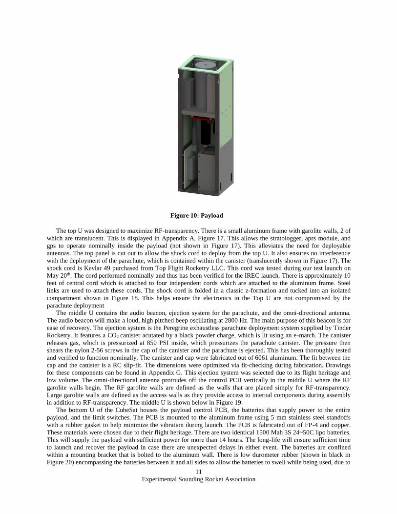
The model was created in Solidworks and analyzed using their mechanical analysis tools. The frame of the
CubeSat is a unique combination of aluminum and garolite to allow full communication through the payload and
structural integrity for high loads, such as landing or the shock from the parachute opening. There are three sections
of the payload; the top U, middle U, and bottom U. The top U houses the parachute canister, the shock cord, GPS,
the stratologger, and the APRS module. The middle U houses the parachute ejection system and an omni-directional
antenna. The bottom U houses the PCB that controls the payload, the batteries, and the limit switches.
The frame was designed using garolite and 6061 aluminum brushed sheets. The engineering design requirements
for the payload include that the top U and part of the middle U be RF-transparent, the payload be easy to assembly,
there be easy access to internal components, and it be able to protect internal components from high velocity impact.
Aluminum 6061 was selected due to its flight heritage, its strength to weight ratio, and machinability. The garolite
was chosen because it is RF-transparent and very strong in compression and especially tension. The garolite
provides structural integrity while maintaining RF-transparency. The garolite was used entirely for two access walls
so during assembly the team could install components while the parachute plate, two aluminum walls, and bottom
plate were assembled; then the garolite walls would be fastened on to complete the structure for flight. The entire
frame was fabricated in-house by the team. The frame can be seen in Figure 10, below.
Experimental Sounding Rocket Association
11
The top U was designed to maximize RF-transparency. There is a small aluminum frame with garolite walls, 2 of
which are translucent. This is displayed in Appendix A, Figure 17. This allows the stratologger, aprs module, and
gps to operate nominally inside the payload (not shown in Figure 17). This alleviates the need for deployable
antennas. The top panel is cut out to allow the shock cord to deploy from the top U. It also ensures no interference
with the deployment of the parachute, which is contained within the canister (translucently shown in Figure 17). The
shock cord is Kevlar 49 purchased from Top Flight Rocketry LLC. This cord was tested during our test launch on
May 20th. The cord performed nominally and thus has been verified for the IREC launch. There is approximately 10
feet of central cord which is attached to four independent cords which are attached to the aluminum frame. Steel
links are used to attach these cords. The shock cord is folded in a classic z-formation and tucked into an isolated
compartment shown in Figure 18. This helps ensure the electronics in the Top U are not compromised by the
parachute deployment
The middle U contains the audio beacon, ejection system for the parachute, and the omni-directional antenna.
The audio beacon will make a loud, high pitched beep oscillating at 2800 Hz. The main purpose of this beacon is for
ease of recovery. The ejection system is the Peregrine exhaustless parachute deployment system supplied by Tinder
Rocketry. It features a CO2 canister acutated by a black powder charge, which is lit using an e-match. The canister
releases gas, which is pressurized at 850 PSI inside, which pressurizes the parachute canister. The pressure then
shears the nylon 2-56 screws in the cap of the canister and the parachute is ejected. This has been thoroughly tested
and verified to function nominally. The canister and cap were fabricated out of 6061 aluminum. The fit between the
cap and the canister is a RC slip-fit. The dimensions were optimized via fit-checking during fabrication. Drawings
for these components can be found in Appendix G. This ejection system was selected due to its flight heritage and
low volume. The omni-directional antenna protrudes off the control PCB vertically in the middle U where the RF
garolite walls begin. The RF garolite walls are defined as the walls that are placed simply for RF-transparency.
Large garolite walls are defined as the access walls as they provide access to internal components during assembly
in addition to RF-transparency. The middle U is shown below in Figure 19.
The bottom U of the CubeSat houses the payload control PCB, the batteries that supply power to the entire
payload, and the limit switches. The PCB is mounted to the aluminum frame using 5 mm stainless steel standoffs
with a rubber gasket to help minimize the vibration during launch. The PCB is fabricated out of FP-4 and copper.
These materials were chosen due to their flight heritage. There are two identical 1500 Mah 3S 24~50C lipo batteries.
This will supply the payload with sufficient power for more than 14 hours. The long-life will ensure sufficient time
to launch and recover the payload in case there are unexpected delays in either event. The batteries are confined
within a mounting bracket that is bolted to the aluminum wall. There is low durometer rubber (shown in black in
Figure 20) encompassing the batteries between it and all sides to allow the batteries to swell while being used, due to
Figure 10: Payload
Experimental Sounding Rocket Association
12
thermal expansion caused by the heating from the usage, such that the mechanical integrity of the bracket remains
intact. The low durometer nature ensures the pressure of the side of the batteries does not exceed the acceptable
limit, when the deformation of the battery would become significant. The material used for this bracket is 6061
aluminum, secured using 6-32 socket head caps and 6-32 flat heads. The bracket is secured in two different
directions to minimize vibration, and consequently the stress on bolts. This material was chosen due to its ease of
fabrication, availability, and flight heritage. The limit switches are integrated into the side of the aluminum frame.
The purpose of the limit switches are to tell the payload when it has been ejected from the rocket. The switches are
compressed inside the rocket within the sabot, which holds the CubeSat. Once the payload has ejected, these
switches are released and the parachute deployment procedure initiates. There are four switches for redundency to
ensure the payload is actually outside the rocket; it uses a majority rules scenario to ensure ejection from the rocket.
The limit switches are secured using epoxy which has been flown before successfully.
To analyze how the structure would respond to landing, the system was put through a drop test simulation in
Solidworks. Figure 21 displays the stress response of this test. The figure shows the maximum stress occurred at the
smaller portion of the aluminum frame. The stress was simulated to be 117 MPa. The theoretical yield strength of
6061 aluminum is 276 MPa. Thus the theoretical factor of safety is 2.36. The garolite displayed little stress. This is
acceptable since those garolite panels are mainly for access. The aluminum is meant to handle the high loading.
This payload has been previously flown and the aluminum withstood the landing impact well. The damage was
minimal and can be re-flown with little adjustments. The terminal velocity of this payload has been calculated to be
approximately 81.51 m/s. This was calculated using equation 8,
(8)
Where; mpayload = 4 kg, g = 9.81 m/s2, CD = 1.05, Apayload = 0.01 m2, ρ = 1.125 kg/m3. The cross-sectional area of the
payload was chosen to be the smallest side, the 10 cm x 10 cm panel on bottom (or top). This ensured the payload
would be prepared for the worst-case scenario shock from parachute opening. The payload should not hit terminal
velocity during descent. The parachute is scheduled to open 4 seconds after ejection from the rocket. Ignoring losses
from air resistance, the payload will reach a velocity of 39.24 m/s. This is attained using the following projectile
motion equation,
(9)
The payload has been designed to withstand the full shock of a parachute being ejected at 81.51 m/s.
Sabot
The sabot is a plastic shell that encapsulates the CubeSat within the drogue bay, and ensures a safe and effective
deployment. The sabot is split into 5 parts. First is the sabot base, which spaces the base of the payload off the top of
the force plate of the booster section to prevent collision between the eye nut at the top of the booster and the bottom
of the payload. Parts two through four are identical sabot leaves, which run the entire length of the payload and form
a snug fit between the wall of the payload and the wall of the drogue bay. The fifth piece of the sabot is a leaf, nearly
identical to parts two through four, but with the addition of a top plate that is connected, and covers the payload and
other three leaves. This top section prevents the drogue parachute from interfering with the CubeSat. This fifth piece
also has a hole going through the length of the part, allowing the shock cord to run from the booster to the avionics
bay, constraining the sabot assembly to the rocket after the ejection charge triggers. The other leaves are connected
with shock cord to the booster directly. Figure 22 shows the assembly of the sabot parts.
Power
The power system is designed with built-in redundancies and multiple factors of safety. The energy source
throughout the flight is provided by two separate but identical 3-cell, 1500mAh lithium polymer batteries. They are
secured in the bottom U of the payload and are encased in a rubber-lined housing which serves to attenuate
vibration, keep the batteries from rubbing against each other, and allow for expansion that may occur if swelling
occurs. Each of these batteries is fed to the main printed circuit board (PCB) at opposite ends using TE
Connectivity’s AMP connector product line which features a locking mate. Although they are identical, one acts as a
Experimental Sounding Rocket Association
13
main power source while the other acts as a backup power source. According to preliminary power consumption
estimates based on datasheets, either battery should be able to independently run the Hyperion system for ~7 hours.
Power-on behavior is initiated when the operator flips the mechanical switch to the “on” position as indicated by
the silk screen. This action electrically connects the backup battery to a linear dropout regulator (LDO) which
generates a 3.3 Volt potential that is used to bias the gate of an N-Channel MOSFET. Biasing this N-Channel
MOSFET then biases a P-Channel MOSFET that is located in series between the backup battery and the rest of the
power system and current is allowed to flow. This is shown in Figure 23.
At this point in the power-on sequence, the main battery is fed into the regulators to generate the voltage rails the
system depends on. For efficiency, the LT3605 switching regulator is used to bring the 11.1V nominal battery
voltage down to 6.5V with an output capability of 5 Amps. The 6.5V rail is inspected through a voltage divider with
an operational amplifier acting as a comparator. The LT6703-3 contains a 400mV internal reference and is powered
from the 3.3V startup rail mentioned before. If the 6.5V rail is under a set threshold of 6.2V, then the output signal
from the LT6703-3 is used as a control signal to route the battery directly to the 5V and 3.3V linear regulators. This
process is shown in Figure 24.
According to simulations through LTSpice, the linear regulators will be fed directly from the battery for a little
over 2 milliseconds. After the 6.5V rail rises above the threshold, the output control signal from the comparator will
instead route the 6.5V rail to the linear regulators. The come-up simulation is shown below in Figure 25. Regardless
of the source, once the 5V rail is present, the Teensy 3.6 microcontroller will initialize and take an analog
measurement of the main battery. If it is deemed acceptable (> 9.9V), then the main battery will be enabled and used
as a power source.
By having control of both batteries, a variety of options becomes available. If the backup battery is desired to be
protected as much as possible, it can be disabled while the main battery is providing the power. If immunity to
power loss is desired, then both batteries can be enabled and if one fails due to something like a rough impact on one
side of the payload during a crucial operation, then both batteries can be enabled. If a failure such as a non-
responsive communications bus occurs and cannot be resolved by restarting the bus, then a hard reset can be self-
imposed by disabling both batteries. Because the initial start-up switch remains flipped, the startup sequence will
automatically restart again with the backup battery.
The power system features two LTC2992 power monitor integrated circuits to measure the voltage and current
from the batteries, 6.5V, 5V, and 3.3V rails. Additionally, LED indication is present for each rail as well as an
indicator for the status of the 6.5V rail. Both measurement and feedback mechanisms are shown below in Figures 26
and 27 respectively.
Due to a large forward voltage drop with the chosen LED, the 3.3V rail must drive a FET to enable its LED.
To summarize, the main benefits to the Hyperion power system are:
1. Enough energy to run for at least 14 hours
2. Reverse-polarity protection
3. Digital control of both power sources
4. Automatic reapplication of power during a failure
5. Low power dissipation with ideal diodes
6. Automatic restructure of power system in the event of a switching regulator failure
7. Ability to hard-reset the system if desired
Controller & Detection
In order to achieve the mission objectives, a sufficient amount of computing speed and power is necessary. After
researching various options, the Teensy 3.6 stood out as the leading contender. With a 32-bit 180 MHz ARM
Cortex-M4 processor and a vast amount of available general-purpose input/output, the Teensy 3.6 met the
requirements. Early prototyping tests showed that there was no issue maintaining a high sampling rate of the inertial
measurement units, radio transmission, SD Card writes, and all of the other miscellaneous tasks that was required.
Another benefit to using this microcontroller is that it is Arduino-compatible. Although the available libraries are far
from efficient, the ability to quickly incorporate drivers for individual sensors was a major benefit – especially since
this project required a concept to deliverable product in less than a year during a full-time educational commitment.
UART, SPI, and I2C communication protocols are used for communicating with various sensors, the SD card,
the GPS receiver, and the LoRa radio. Digital outputs are utilized to control on-board LED indication, an external
strobe, a buzzer, and ematch actuation. Two of these sub-circuits are shown in Figure 28.
Experimental Sounding Rocket Association
14
It should be noted that both the buzzer and the strobe are enabled by default and the controller can only disable
these. Typically, both the strobe and buzzer will by cycled in order for the payload to be more detectable. In the
event that the controller fails, the strobe and buzzer will be constantly enabled until there is no remaining power.
Analog inputs are used to read voltages such as the main battery and to detect the presence and status of the
electric matches used for deploying the parachute. Four digital pins are used as inputs to detect the state of four
discrete mechanical switches which detect if the payload is still inside of the rocket or if it has been deployed. The
circuitry associated with these mechanical switches is shown below in Figure 29.
The series 1kΩ resistor and following 10nF capacitor serve to provide an element of hardware debouncing for
when the switch is in a state where it is just on the threshold of being open or closed. There is also a software
debounce which is much more robust and is covered in the software section.
Sensors
Besides controlling mission-critical events such as parachute deployment, the primary purpose of the Hyperion
payload is to provide and store real-time self-diagnostics, telemetry, and sensor data. Because of this, there are
plenty of pieces of information which were considered as part of the design process. For the power system, each
power rail is measured in terms of voltage and current. This information is gathered from the LTC2992 integrated
circuits and is available through an I2C interface. The control signal output of the operational amplifier comparator
which inspects the 6.5V rail is also input to the Teensy 3.6.
For generic data that can be used for future testing models, there is a wide variety gathered from multiple
sensors. Acceleration, angular rate, and magnetic-field orientation are obtained from the LSM9DS1. Additionally,
acceleration up to +/- 24g’s is obtained from the LIS331. The main purpose of the LSM9DS1 is to calculate pitch,
roll, and yaw to transmit for real-time 3D orientation visualization. The LIS331 was chosen so that a wider range of
acceleration data can be gathered. Both of these sensors are read from the sensor SPI bus so that a higher rate can be
used. Temperature, pressure, and humidty are gathered from the BME280 which communicates on the sensor I2C
bus. The BME280 is also used to to calibrate the next sensor, the CCS811. The CCS811 is a nonvolatile organic gas
sensor. Since the payload uses compressed CO2, this sensor can be used to detect any leaks that may occur.
Although the payload is not completely sealed, the parts per million (ppm) of CO2 detected will increase
dramatically in the event of a leak. Altitude is gathered from the Stratologger altimeter through a UART link. GPS
data is obtained from the GPS receiver through another UART link. Although the originally designed airbags will
not be flying for IREC 2018, the board also features a pressure transducer which contains a barbed input for a
flexible tube. The other side of the flexible tube is connected to a 1/4” NPT to barb adapter and is screwed into a
1/4” tee linked to the balloon inflation network.
Finally, and most importantly, mission-critical elements such as the mechanical deployment switches and the
electric matches are read in by the Teensy. The deployment switches, mentioned in the detection section, are read as
either “high” or “low” by the Teensy. By implementing a software debounce, the switches can only be detected as
truly opened when multiple consecutive reads have been received for a majority of the switches. These switches are
also read during the remote arming phase to make sure the payload is correctly sitting in the rocket to ensure that the
parachute is not deployed inside of the rocket. The same goes for the electric matches. If connected properly and not
defective, the Teensy will see the input as being “high”. Otherwise, a pull-down resistor will cause it to read “low.”
These readings of these mission-critical elements help to ensure mission success.
Actuation
With the exception that the power comes from the main PCB, the Stratologger is a completely redundant system
that can trigger its own ematch at a set programmed altitude of 1700 feet. If the Hyperion PCB fails to properly
trigger the ematch or if the ematch is defective despite having continuity, then the Stratologger will independently
fire the ematch on its own. This happened on a test flight when the payload was unable to be armed inside of the
rocket due to a mechanical failure. The Peregrine CO2 depoyment mechanism used for parachute deployment is able
to fit 2 ematches at once. With one being controlled by the Hyperion PCB and the other being controlled as a last
resort by the stratologger, there is redundancy in actuation.
The actual firing of the ematch is done in two stages. For reference, see Figure 30. The first stage arms the
ematch by allowing the battery voltage to be present on one side of the device. When this occurs, a red LED will be
illuminated showing that the match is armed and ready to fire. In the event of the launch, the ematches are enabled
as soon as deployment is detected. Four seconds later, when the payload is sufficiently separated from the rocket and
the rocket’s shock cord, the ematch will fire by enabling the second stage and completing the circuit, allowing
Experimental Sounding Rocket Association
15
current to flow through the match. It should be noted that in order to properly “check” the ematch, it must be armed.
This occurs briefly and then is disabled after the measurement is taken. As part of the pre-launch process, a
measurement is first taken before the payload enters the rocket and is then taken right before launch.
As mentioned in the sensor section, the original design of this system involved an airbag. Although it was cut in
order to maintain successful functionality of other subsystems, the PCB does have the ability to power and control a
servo motor for future revisions of the payload. The circuitry is shown below in Figure 31.
The control of this servo includes a fly back diode which will dissipate the energy stored in the inductive load
when disabled. The ability to enable and disable power to the servo motor improves power draw considerations and
is also warranted in the event that the switching regulator fails and the 6.5V is not adequately created.
Communication
The Hyperion payload features two forms of communication for redundant tracking purposes. The radio installed
on the PCB is the RFM69HCW which is a 915MHz LoRa module. This module communicates on its own SPI bus
for code efficiency and safety considerations so that the chance for conflict errors is minimal. This module is broken
out to an SMA connector which is interfaced with a quarter-wave omni-directional dipole antenna. The SMA is
angled at 90 degrees such that it faces upwards into the center U of the payload which has the rf-transpared g10
material on all four sides. Testing shows that roughly 20 messages per second can be sent. This amount of resolution
should be good enough to obtain a decent model of the pitch, roll, and yaw in real-time. Other pieces of information
are sent at a rate of once every second to once every 5 to 10 seconds, depending on the type of data. The
transmissions are received with a 915MHz direction patch antenna connected to a commercial off-the-shelf (COTS)
Adafruit RFM9x 915 MHz LoRa module. This module is linked to and processed by another Teensy 3.6. The
Teensy is connected to a PC through the serial interface which is used to relay the data to the HABnet data
visualizer. The combination of these devices is referred to as the “ground station”. If the payload encounters any
major failures, it will enter a “safety” state in which everything but GPS coordinates are transmitted to the ground
station.
The GPS receiver used for this mission is the uBLOX MAX M8-Q. The receiver antenna for the GPS is a COTS
weatherproof antenna which is located in the top U of the payload. Because most satellites that can be locked onto
will be higher in altitude, it is important for the GPS antenna to be located as high as possible. The top four walls
and the ceiling of the payload are made from G10 as well to assist in obtaining a good GPS lock. This antenna is fed
down to the bottom U where the PCB is installed and connected through a SMA to uFL adapter.
In the event that the communications or GPS receiver from the Hyperion PCB should fail, the Tracksoar APRS
(automated packet reporting system) module is included in the payload as a redundant tracking mechanism. This
device is completely independent from the rest of the electronics and even has its own power supply in the form of 2
AA batteries. It is also included in the top U of the payload to get as good a GPS lock as possible and transmits its
data on 144.390 MHz as packets. This frequency is commonly used by HAM radio operators all over the United
States to track objects. Many operators use repeaters and have their stations linked to a global network which can be
seen at https://aprs.fi/. Because it is unlikely that networked tracking will be available in the desert during the
competition, the packets will be received directly with a Baofeng UV-5r with an upgraded Nagoya NA-771 15.6”
whip antenna. The speaker output of the radio is connected to the mic input of an android phone which runs the
APRS Droid application. This application can locally decode the received packets and provide the GPS coordinates
which have been sent.
After parachute deployment, recovery of the payload is the next most important task. With two forms of
communication that each have their own GPS receiver and radio transmitter, the odds of recovery are already pretty
good. However, to further increase these odds, a loud buzzer and a bright strobe LED is incorporated. It is unknown
if the strobe LED will be bright enough to see while the payload is still thousands of feet in the air, but it should
serve to increase the chance of recovery regardless. Because of the immense factor of safety with the battery life, the
payload should continue to have power, transmit its location, toggle the buzzer, and blink the strobe LED even into
the night when it will only become more visible. In the event that the controller gets locked up, the buzzer and strobe
LED are enabled by default. As long as the controller isn’t frozen while holding those control pins low, they should
be working as long as battery power is present.
System Software
The system software is at the heart of the Hyperion payload. It controls mission critical subsystems, collects and
logs output from sensors, controls communication to the ground station and maintains responsibility for handling

Experimental Sounding Rocket Association
16
mission events. System software running on the payload from the beginning was designed to be held to a high
degree of reliability and redundancy. Varying degrees of redundancy were also achieved within the system software
mainly in relation to sensor or hardware failure. From its core, the system software can be segmented into four main
parts: (1) Dynamic Scheduling Queue, (2) Core system routines along with necessary utilities, (3) Hyperion
communications protocol and (4) Sensor/Hardware drivers.
The Dynamic System Queue is a light weight multi-threaded real time operating system (RTOS) used to provide
dynamic execution of routines within the system. At the very core of the Hyperion system software is the DSQ.
Routines within the system are placed within the DSQ and then scheduled. Routines are scheduled using a priority
based system which allows for execution relative to other routines in the system.
Routines within the system are pieces of code which can be run within the DSQ. These routines handle
everything within the system after start up. Depending on the function of the routine, a static or dynamic priority
value is assigned to each one. In general, routines which handle mission critical events are assigned values which
correlate to a higher priority. These higher priority routines will execute more often than lower priority routines.
The Hyperion Protocol defines communication between the payload and ground station. The protocol includes
information on packing and unpacking sensor/general data, layout of packed values, maximum bit lengths accepted
and arming/disarming sequence. The protocol library was written in C++ and can be used with a microprocessor and
desktop architectures.
Methodology
This section will outline methodology for mission critical components of the system software. Below is how
deployment is detected, arming/disarming and phases/phase switching works within the system software.
Placed on the outside wall of the payload are four limit switches used to detect deployment. These switches
while inside of the payload adapter will be pressed in, reading no voltage across them. When depressed the switches
will be open and read a maximum of 5 volts. These switches are checked against a "priority rules" situation where
three or four switches need to be open for the deployment check to pass validation. In the case where two switches
are open and two closed, the rate of climb measured by the payload will need to be greater than 15m/s downward. In
total, the deployment validation sequence will take one second to complete. This time interval of one second will
account for switches which could open and close quickly due to vibrations during launch.
Arming and disarming of the payload will occur remotely; due to this, commands to disarm and arm the payload
were built into the Hyperion protocol. To arm the payload, the payload sends a status message which informs the
ground station of the current status of the payload (armed/disarmed). Then the ground station sends a command to
ether arm or disarm the payload. If the payload is in the same phase as the command, nothing happens. If the
payload is disarmed and receives an armed command, the payload checks if it is okay to arm. To successfully pass
the arming check, the deployment switches on the payload must be all closed. This is done as to not accidentally
trigger deployment while still inside of the launch vehicle. If the payload is armed and receives a disarm command,
the payload immediately switches over to the disarmed phase.
Within the system, three phases exist in which separate sets of software are run. The three phases include the
SAFE, MAIN and DONE phase. In the SAFE phase, the payload is disarmed and incapable of triggering mission
events (deployment, parachutes). In the MAIN phase the payload is armed and running all mission critical software.
In the DONE phase, the payload has landed and is awaiting recovery. This last phase is triggered 20 minutes after
deployment.
The ground station created to interact with the Hyperion payload contains software which is used to arm/disarm
the payload, collect transmissions via the Hyperion Protocol and visualize data in real-time. The ground station can
be separated into two distinct parts which combine to form a unified system. The two distinct parts include system
forwarder and a desktop/laptop used to serve as an interface.
The system forwarder consists of a micro-controller with a connected radio communication module. This system
will be responsible for collecting data transmitted from the payload, forwarding the data over serial to the interface
and arming/disarming the payload with user supplied commands via serial.
The interface will be responsible for displaying all information collected and sent to the Hyperion payload. The
interface will be running a piece of software developed in-house called HABnet. HABnet has the capability to show
data in graphical form as well as the orientation (Pitch, Roll, Yaw) of the payload with a 3D model of the Hyperion
payload in real-time.
Experimental Sounding Rocket Association
17
III. Mission Concept of Operations Overview
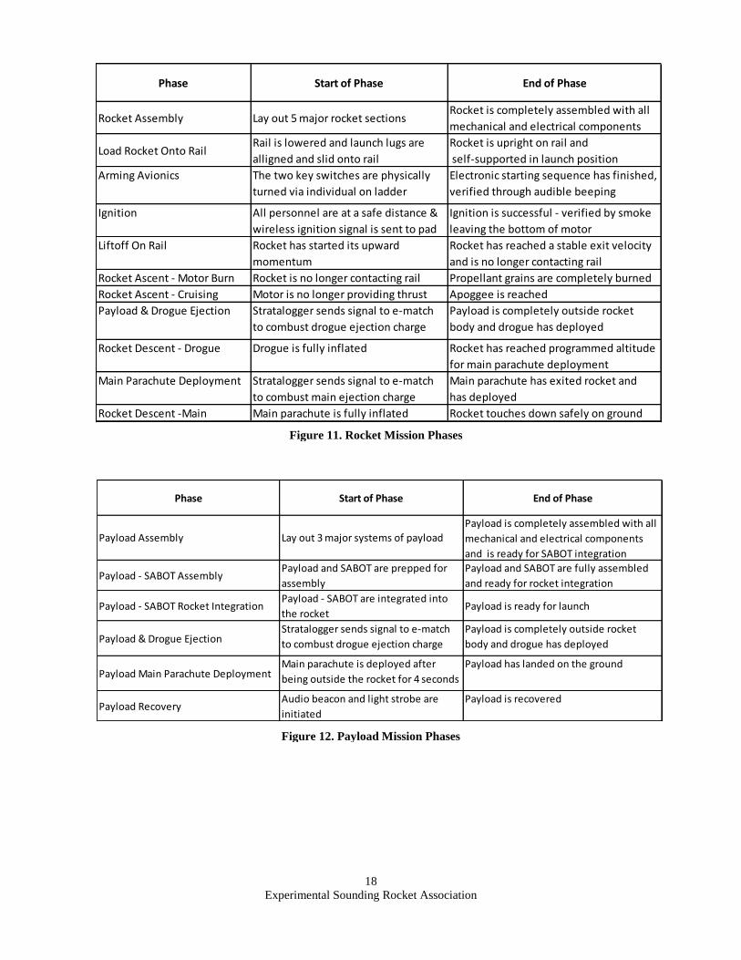
From the beginning of rocket assembly to the final rocket touch down, 11 mission phases have been identified.
The first is rocket assembly. The launch preparation station will be set up and the 5 main sections of the rocket will
be laid out. The sub teams will simultaneaously prepare the motor, avionics, and parachutes. The motor components
will be prepared and assembled on a clean surface. It will then be loaded into the booster and secured via eye-nut.
The avionics sled will come with all electronics mounted on it. The black powder will be loaded and sealed into
their canisters with an e-match embedded. The charges will be attached, batteries connected, and wires secured.
Once the sled is complete, it is loaded into the avionics bay and the bulkheads are secured on either end. The
parachutes are then loaded into their bays with respective shock cords, quick links, swivels, and flame blankets. The
avionics bay and the payload are then combined and screwed together through threaded holes in the body tube. The
main parachute bay is then attached in the same manner. The nose cone is attached to this assembly. It is secured
using 4 nylon shear pins. Finally, this assembly is attached to the booster and secured using 2 nylon shear pins.
These attachments will be the two points of separation for parachute ejection.
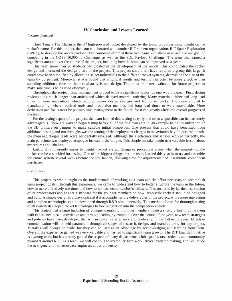
The payload has three systems that must be assembled before rocket integration. They are the parachute ejection
system, power system, and the shock cord. The parachute ejection system integration procedure is as follows: epoxy
two e-matches into position, load the black powder using premade measuring cups, insert the 8g CO2 canister, and
screw on the ejection system to the parachute canister. The power must be supplied to the payload by connecting the
terminals from the batteries to the control PCB. The shock cord must then be folded in a z-formation and placed into
the isolation room inside the top U. Once complete, the payload is ready to be integrated into the rocket. Once inside
the rocket, the payload is armed using a remote command carried out by the project leader. The payload is then
ready for launch.
The fully assembled rocket will be carried to the pad by several team members. The rail will be lowered and the
rocket launch lugs will be aligned with it. One member supporting the booster, one member supporting the nose
cone, and one spotter will carefully slide the rocket onto the rail. Once the rocket is at the bottom of the rail, the rail
will be raised and oriented to a specific angle depending on the launch conditions. The rocket will be locked down
and the igniter will be inserted into the booster. Then begins arming. A ladder will be used to reach the arming key
switches on the outside of the avionics bay. The first switch will be turned to arm the stratologger. It will go through
its starting sequence and once it reaches steady state, the egg-timer will be armed. After it finishes its sequence, both
keys will be removed, locking them in place. The team will return to safety and when cleared for launch, a wireless
signal will be sent to the igniter. If it is a successful ignition, smoke will appear from the bottom of the rocket and
shortly after the rocket will begin lift-off.
The lift-off on the rail is considered a phase because of it’s critical importance in achieving a stable flight. A
minimum velocity of 42 ft/s must be achieved off the rail and this rocket should reach 104 ft/s. If this velocity is
achieved and the rocket is no longer in contact with the rail, this phase will be completed. The rocket will now
ascend due to the thrust force imparted by the M-class motor. This motor will impart thrust for 4.2 seconds until the
6 fuel grains are completely exhausted. Once they are burned out, the motor burn phase comes to an end. The rocket
now abides by the laws of projectile motion and it’s performance will depend on the intial burnout velocity and
weather conditions such as wind. When gravity and drag finally bring the rocket’s acceleration to zero, it will have
reached apogee.
After the rocket reaches apogee, the pressure readings of the stratologger will trigger a switch to open the circuit
that sends current into the e-match. The e-match will ignite the black powder charge and the pressure force will push
the drogue parachute and payload out of the rocket bay. Once the payload is completely clear and the drogue
parachute has been inflated, this stage is complete. The rocket will then decend at a rate of 55 ft/s for 160 seconds
with the drogue deployed. At an altitude of 1,000 feet, the stratologger triggers the main ejection charge and the
main parachute is deployed. After deployment, the rocket will fall at 18 ft/s for 55 seconds until it safely touches
down.
Experimental Sounding Rocket Association
18
Phase Start of Phase End of Phase
Rocket Assembly Lay out 5 major rocket sectionsRocket is completely assembled with all
mechanical and electrical components
Load Rocket Onto RailRail is lowered and launch lugs are
alligned and slid onto rail
Rocket is upright on rail and
self-supported in launch position
Arming Avionics The two key switches are physically
turned via individual on ladder
Electronic starting sequence has finished,
verified through audible beeping
Ignition All personnel are at a safe distance &
wireless ignition signal is sent to pad
Ignition is successful - verified by smoke
leaving the bottom of motor
Liftoff On Rail Rocket has started its upward
momentum
Rocket has reached a stable exit velocity
and is no longer contacting rail
Rocket Ascent - Motor Burn Rocket is no longer contacting rail Propellant grains are completely burned
Rocket Ascent - Cruising Motor is no longer providing thrust Apoggee is reached
Payload & Drogue Ejection Stratalogger sends signal to e-match
to combust drogue ejection charge
Payload is completely outside rocket
body and drogue has deployed
Rocket Descent - Drogue Drogue is fully inflated Rocket has reached programmed altitude
for main parachute deployment
Main Parachute Deployment Stratalogger sends signal to e-match
to combust main ejection charge
Main parachute has exited rocket and
has deployed
Rocket Descent -Main Main parachute is fully inflated Rocket touches down safely on ground
Phase Start of Phase End of Phase
Payload Assembly Lay out 3 major systems of payload
Payload is completely assembled with all
mechanical and electrical components
and is ready for SABOT integration
Payload - SABOT AssemblyPayload and SABOT are prepped for
assembly
Payload and SABOT are fully assembled
and ready for rocket integration
Payload - SABOT Rocket IntegrationPayload - SABOT are integrated into
the rocketPayload is ready for launch
Payload & Drogue EjectionStratalogger sends signal to e-match
to combust drogue ejection charge
Payload is completely outside rocket
body and drogue has deployed
Payload Main Parachute DeploymentMain parachute is deployed after
being outside the rocket for 4 seconds
Payload has landed on the ground
Payload RecoveryAudio beacon and light strobe are
initiated
Payload is recovered
Figure 11. Rocket Mission Phases
Figure 12. Payload Mission Phases
Experimental Sounding Rocket Association
19
IV Conclusion and Lessons Learned
Lessons Learned
Third Time’s The Charm is the 3rd high-powered rocket developed by the team, providing some insight on the
rocket’s name. For this project, the team collaborated with another RIT student organization, RIT Space Exploration
(SPEX), to develop the rocket payload. The combined effort of these two teams will allow us to achieve our goal of
competing in the COTS 10,000 ft. Challenge, as well as the SDL Payload Challenge. The team has learned a
significant amount over the course of the project, including how the team can be improved next year.
This year, more than 20 students participated in the development of the rocket. This complicated the rocket
design and increased the design phase of the project. This project should not have required a group this large, it
could have been simplified by allocating select individuals to the different rocket systems, decreasing the size of the
team by 50 percent. Moreover, it was found that empirical results and testing can often be more effective than
spending additional time on theoretical analysis and design. This must be better evaluated for future projects to
make sure time is being used effectively.
Throughout the project, time management proved to be a significant factor, as one would expect. First, design
reviews took much longer than anticipated which delayed material ordering. Many materials either had long lead
times or were unavailable which required minor design changes and led to set backs. The same applied to
manufacturing, where required tools and production methods had long lead times or were unavailable. More
dedication and focus must be put into time management in the future, for it can greatly affect the overall progress of
the team.
For the testing aspect of the project, the team learned that testing as early and often as possible can be extremely
advantageous. There are ways to begin testing before all of the final parts are in, an example being the utilization of
the 3D printers on campus to make suitable initial prototypes. One process that could have benefitted from
additional testing and run-throughs was the arming of the deployment charges in the avionics bay. In our test launch,
the main and drogue leads were accidentally reversed. Although the electronics and sensors worked perfectly, the
main parachute was deployed at apogee instead of the drogue. This simple mistake taught us a valuable lesson about
procedures and labeling.
Lastly, it is inherently easier to identify rocket system design or procedural errors when the majority of the
rocket can be assembled for testing. One of the biggest things that the team learned this year is to try and assemble
the entire system several weeks before the test launch, allowing time for adjustments and last-minute component
purchases.
Conclusion
This project as whole taught us the fundamentals of working as a team and the effort necessary to accomplish
team project goals. Through this experience, we came to understand how to better structure the team in the future,
how to more effectively use time, and how to harness team member’s skillsets. This rocket is by far the best version
of its predecessors and has set a standard for the younger members on how large-scale rockets should be designed
and built. A simple design is always optimal if it accomplishes the deliverables of the project, while more interesting
and complex technologies can be developed through R&D simultaneously. This method allows for thorough testing
of all custom developed rocket technologies before integration into the competition vehicle.
This project had a large inclusion of younger members; the older members made a strong effort to guide them
with experience-based knowledge and through leading by example. Over the course of the year, new team strategies
and policies have been developed that will increase the efficiency and leadership in the following years. Effective
communication will be held paramount through all stages of research, design, and manufacturing for any project.
Mistakes will always be made, but they can be used as an advantage by acknowledging and learning from them.
Overall, the experience gained was very valuable and has led to significant team growth. The RIT Launch Initiative
is a young team, but has already gained the respect of many departments, clubs, professors, students, and community
members around RIT. As a team, we will continue to exemplify hard work, ethical decision making, and will guide
the next generation of aerospace engineers at our university.

Experimental Sounding Rocket Association
20
Appendix A: Additional Subsystem Information
Figure 13: Propulsion Components
Figure 14: Drogue Parachute
Figure 15: Main Parachute
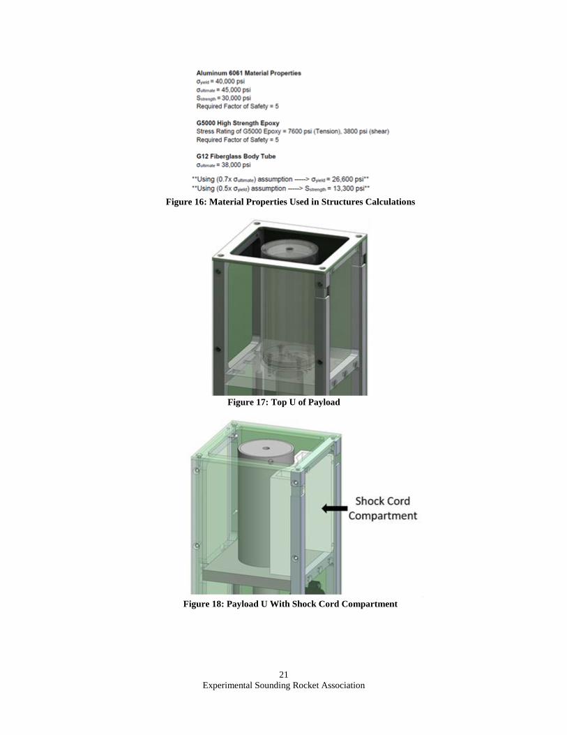
Experimental Sounding Rocket Association
21
Figure 16: Material Properties Used in Structures Calculations
Figure 17: Top U of Payload
Figure 18: Payload U With Shock Cord Compartment
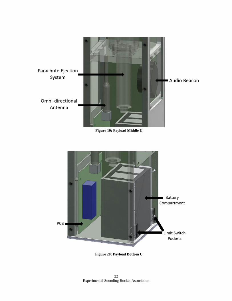
Experimental Sounding Rocket Association
22
Figure 19: Payload Middle U
Figure 20: Payload Bottom U

Experimental Sounding Rocket Association
23
Figure 21: Payload Structural Analysis
Figure 22: Sabot Layout
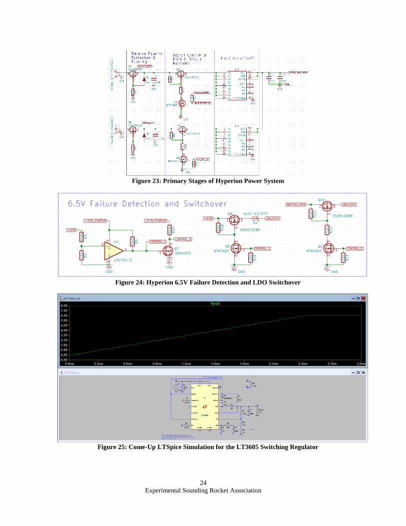
Experimental Sounding Rocket Association
24
Figure 23: Primary Stages of Hyperion Power System
Figure 24: Hyperion 6.5V Failure Detection and LDO Switchover
Figure 25: Come-Up LTSpice Simulation for the LT3605 Switching Regulator
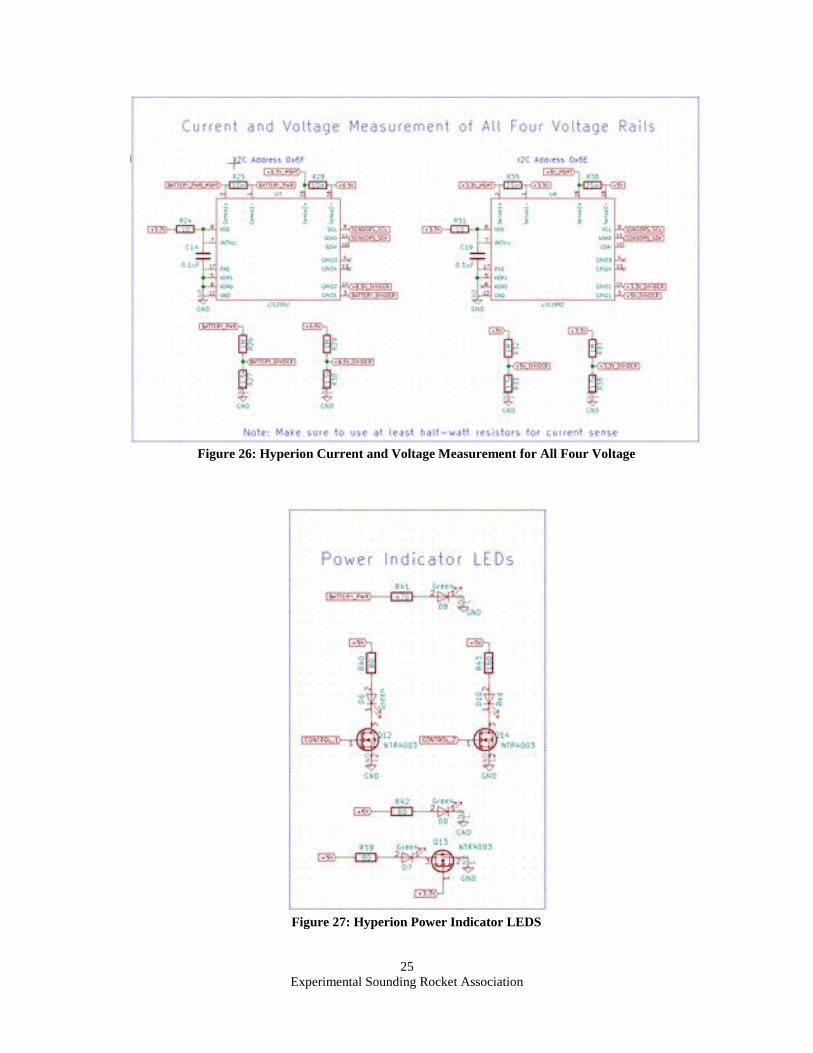
Experimental Sounding Rocket Association
25
Figure 26: Hyperion Current and Voltage Measurement for All Four Voltage
Figure 27: Hyperion Power Indicator LEDS

Experimental Sounding Rocket Association
26
Figure 28: Hyperion Off-Board Buzzer and Strobe LED Control Circuitry
Figure 29: Hyperion Mechanical Deployment Detection Switches
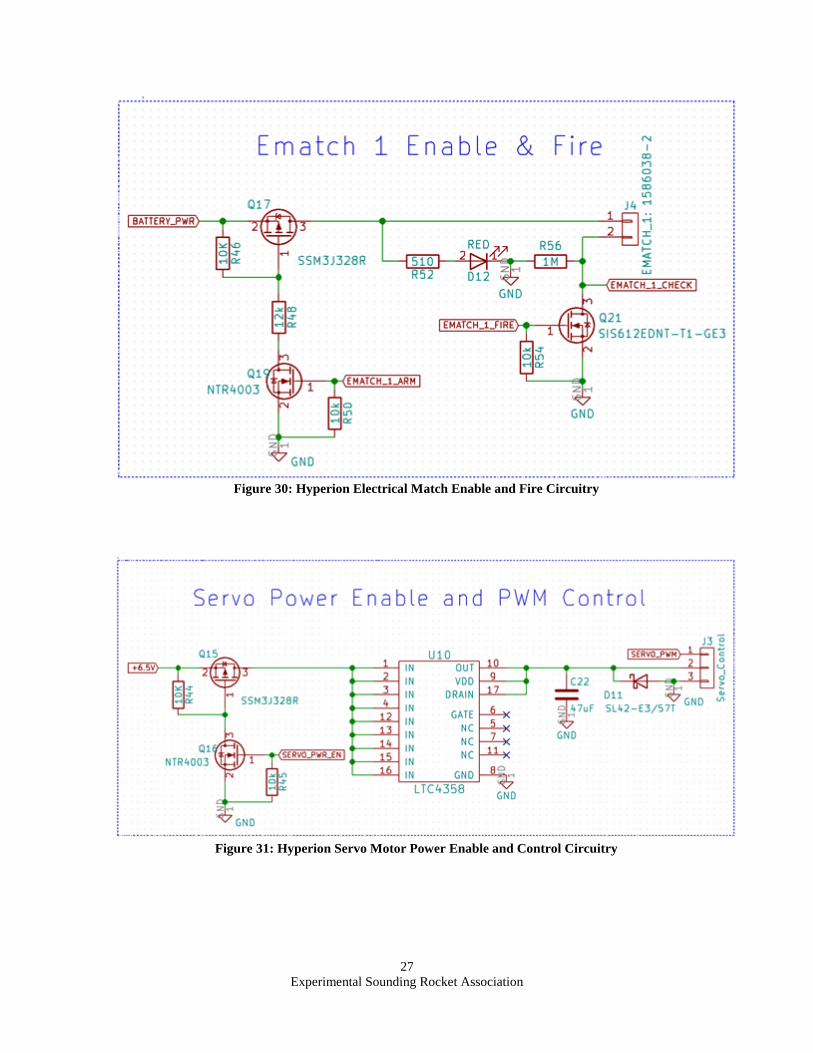
Experimental Sounding Rocket Association
27
Figure 30: Hyperion Electrical Match Enable and Fire Circuitry
Figure 31: Hyperion Servo Motor Power Enable and Control Circuitry
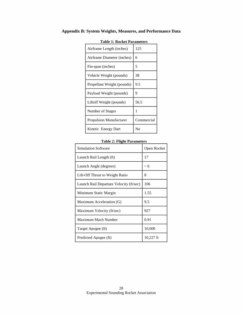
Experimental Sounding Rocket Association
28
Appendix B: System Weights, Measures, and Performance Data
Table 1: Rocket Parameters
Airframe Length (inches) 125
Airframe Diameter (inches) 6
Fin-span (inches) 5
Vehicle Weight (pounds) 38
Propellant Weight (pounds) 9.5
Payload Weight (pounds) 9
Liftoff Weight (pounds) 56.5
Number of Stages 1
Propulsion Manufacturer Commercial
Kinetic Energy Dart No
Table 2: Flight Parameters
Simulation Software Open Rocket
Launch Rail Length (ft) 17
Launch Angle (degrees) ~ 6
Lift-Off Thrust to Weight Ratio 8
Launch Rail Departure Velocity (ft/sec) 106
Minimum Static Margin 1.55
Maximum Acceleration (G) 9.5
Maximum Velocity (ft/sec) 927
Maximum Mach Number 0.91
Target Apogee (ft) 10,000
Predicted Apogee (ft) 10,227 ft
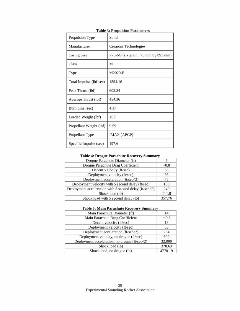
Experimental Sounding Rocket Association
29
Table 3: Propulsion Parameters
Propulsion Type Solid
Manufacturer Cesaroni Technologies
Casing Size P75-6G (six grain, 75 mm by 893 mm)
Class M
Type M2020-P
Total Impulse (lbf-sec) 1894.16
Peak Thrust (lbf) 602.34
Average Thrust (lbf) 454.36
Burn time (sec) 4.17
Loaded Weight (lbf) 15.5
Propellant Weight (lbf) 9.59
Propellant Type IMAX (APCP)
Specific Impulse (sec) 197.6
Table 4: Drogue Parachute Recovery Summary
Drogue Parachute Diameter (ft) 5
Drogue Parachute Drag Coefficient ~0.8
Decent Velocity (ft/sec) 55
Deployment velocity (ft/sec) 93
Deployment acceleration (ft/sec^2) 75
Deployment velocity with 5 second delay (ft/sec) 180
Deployment acceleration with 5 second delay (ft/sec^2) 240
Shock load (lb) 111.8
Shock load with 5 second delay (lb) 357.76
Table 5: Main Parachute Recovery Summary
Main Parachute Diameter (ft) 14
Main Parachute Drag Coefficient ~ 0.8
Decent velocity (ft/sec) 18
Deployment velocity (ft/sec) 53
Deployment acceleration (ft/sec^2) 254
Deployment velocity, no drogue (ft/sec) 600
Deployment acceleration, no drogue (ft/sec^2) 32,000
Shock load (lb) 378.63
Shock load, no drogue (lb) 4770.19
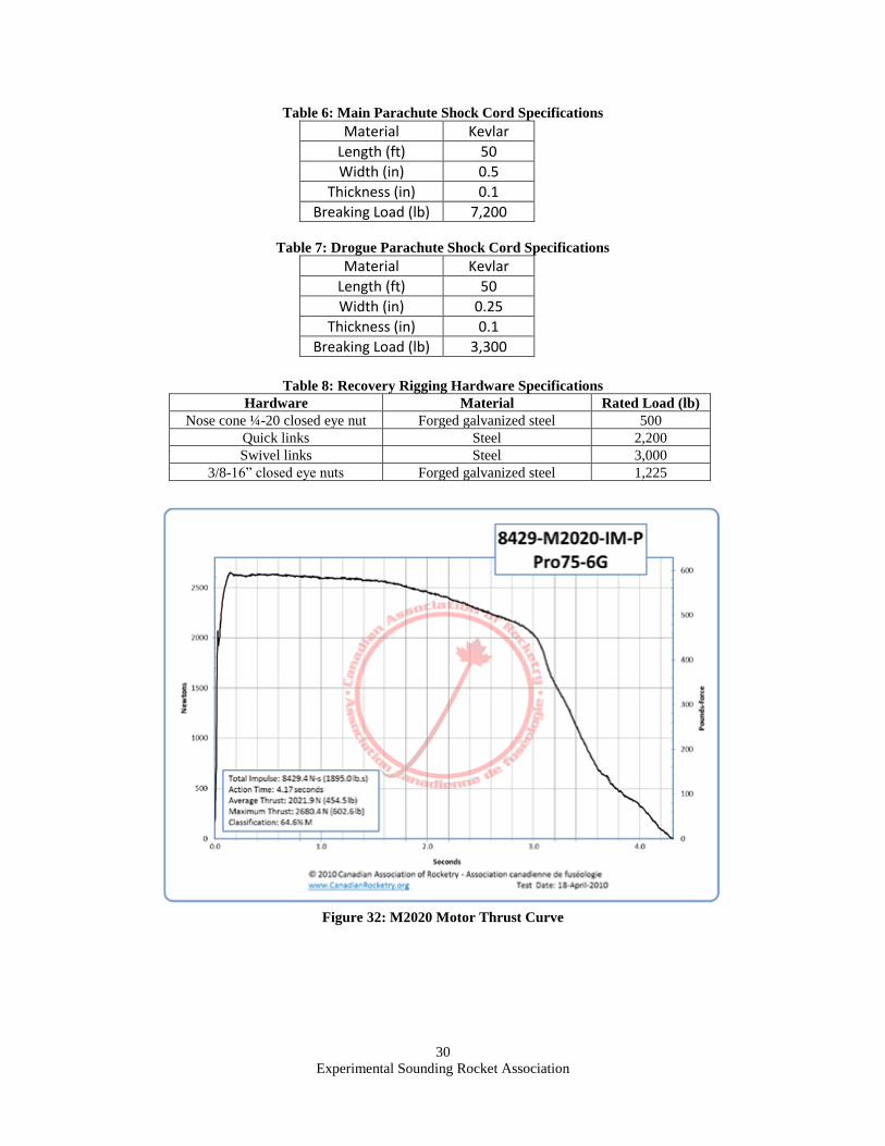
Experimental Sounding Rocket Association
30
Table 6: Main Parachute Shock Cord Specifications
Material Kevlar
Length (ft) 50
Width (in) 0.5
Thickness (in) 0.1
Breaking Load (lb) 7,200
Table 7: Drogue Parachute Shock Cord Specifications
Material Kevlar
Length (ft) 50
Width (in) 0.25
Thickness (in) 0.1
Breaking Load (lb) 3,300
Table 8: Recovery Rigging Hardware Specifications
Hardware Material Rated Load (lb)
Nose cone ¼-20 closed eye nut Forged galvanized steel 500
Quick links Steel 2,200
Swivel links Steel 3,000
3/8-16” closed eye nuts Forged galvanized steel 1,225
Figure 32: M2020 Motor Thrust Curve
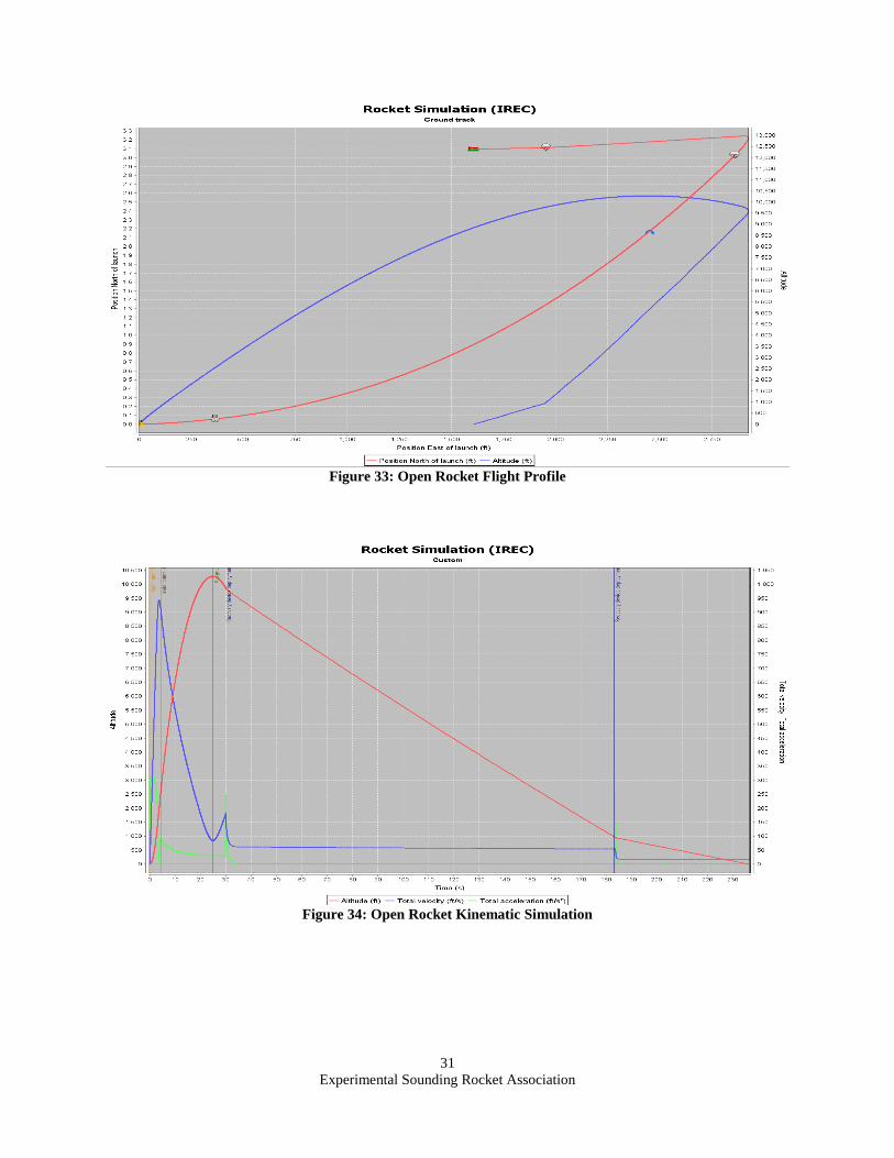
Experimental Sounding Rocket Association
31
Figure 33: Open Rocket Flight Profile
Figure 34: Open Rocket Kinematic Simulation
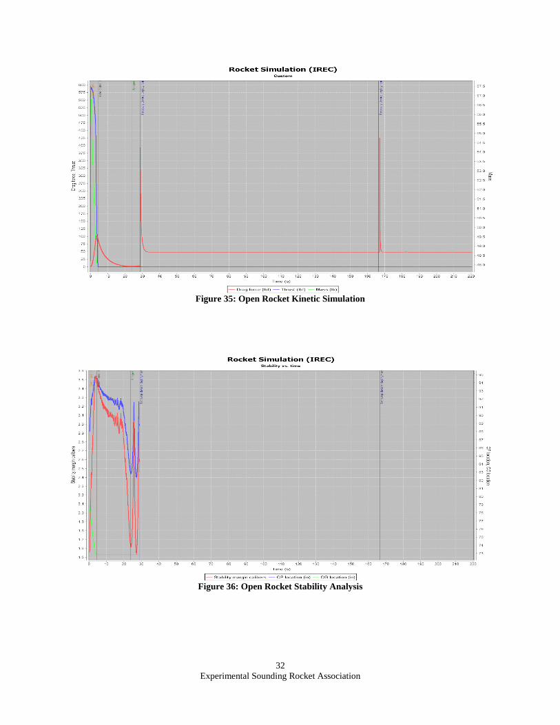
Experimental Sounding Rocket Association
32
Figure 35: Open Rocket Kinetic Simulation
Figure 36: Open Rocket Stability Analysis
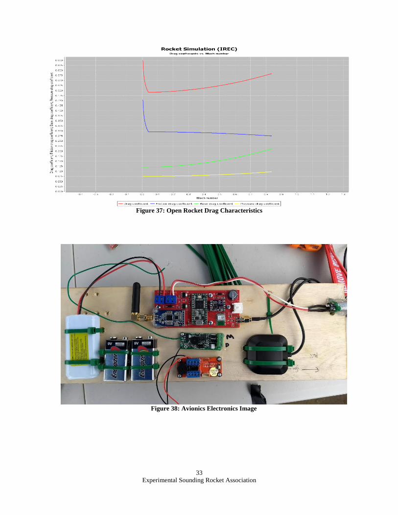
Experimental Sounding Rocket Association
33
Figure 37: Open Rocket Drag Characteristics
Figure 38: Avionics Electronics Image
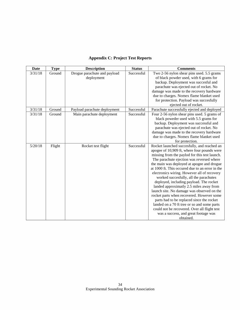
Experimental Sounding Rocket Association
34
Appendix C: Project Test Reports
Date Type Description Status Comments
3/31/18 Ground Drogue parachute and payload
deployment
Successful Two 2-56 nylon shear pins used. 5.5 grams
of black powder used, with 6 grams for
backup. Deployment was succesful and
parachute was ejected out of rocket. No
damage was made to the recovery hardware
due to charges. Nomex flame blanket used
for protection. Payload was succesfully
ejected out of rocket.
3/31/18 Ground Payload parachute deployment Successful Parachute successfully ejected and deployed
3/31/18 Ground Main parachute deployment Successful Four 2-56 nylon shear pins used. 5 grams of
black poweder used with 5.5 grams for
backup. Deployment was successful and
parachute was ejected out of rocket. No
damage was made to the recovery hardware
due to charges. Nomex flame blanket used
for protection.
5/20/18 Flight Rocket test flight Successful Rocket launched succesfully, and reached an
apogee of 10,909 ft, where four pounds were
missing from the paylod for this test launch.
The parachute ejection was reversed where
the main was deployed at apogee and drogue
at 1000 ft. This occured due to an error in the
electronics wiring. However all of recovery
worked succesfully, all the parachutes
deployed, including payload. The rocket
landed approximatly 2.5 miles away from
launch site. No damage was observed on the
rocket parts when recovered. However some
parts had to be replaced since the rocket
landed on a 70 ft tree or so and some parts
could not be recovered. Over all flight test
was a success, and great footage was
obtained.
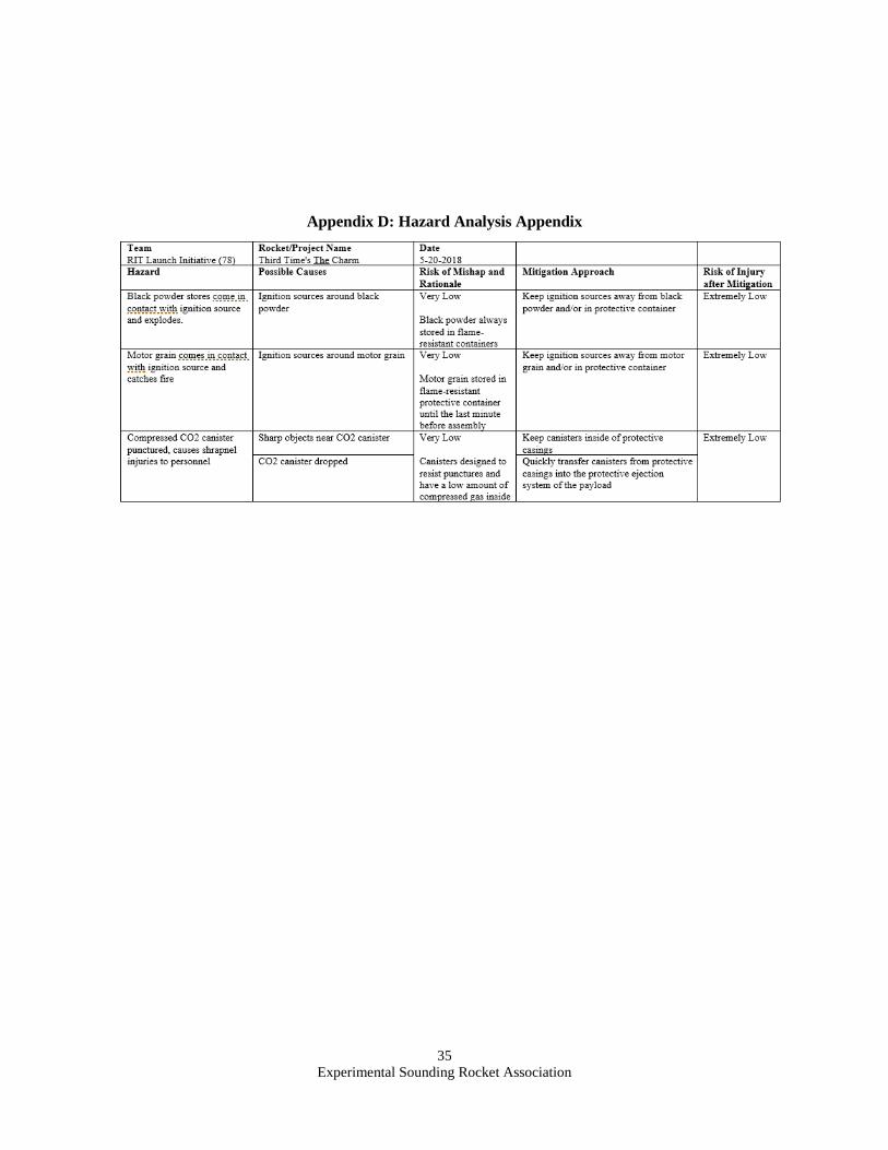
Experimental Sounding Rocket Association
35
Appendix D: Hazard Analysis Appendix
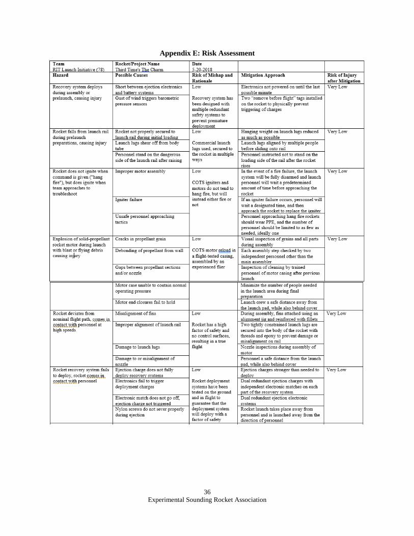
Experimental Sounding Rocket Association
36
Appendix E: Risk Assessment
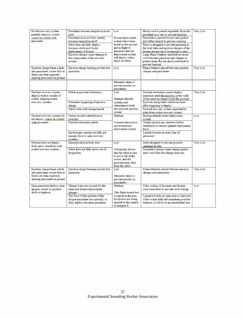
Experimental Sounding Rocket Association
37
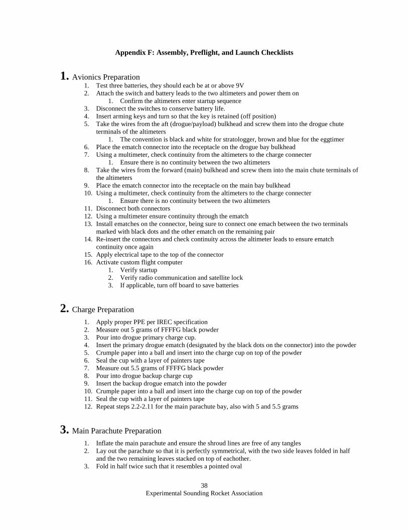
Experimental Sounding Rocket Association
38
Appendix F: Assembly, Preflight, and Launch Checklists
1. Avionics Preparation 1. Test three batteries, they should each be at or above 9V
2. Attach the switch and battery leads to the two altimeters and power them on
1. Confirm the altimeters enter startup sequence
3. Disconnect the switches to conserve battery life.
4. Insert arming keys and turn so that the key is retained (off position)
5. Take the wires from the aft (drogue/payload) bulkhead and screw them into the drogue chute
terminals of the altimeters
1. The convention is black and white for stratologger, brown and blue for the eggtimer
6. Place the ematch connector into the receptacle on the drogue bay bulkhead
7. Using a multimeter, check continuity from the altimeters to the charge connecter
1. Ensure there is no continuity between the two altimeters
8. Take the wires from the forward (main) bulkhead and screw them into the main chute terminals of
the altimeters
9. Place the ematch connector into the receptacle on the main bay bulkhead
10. Using a multimeter, check continuity from the altimeters to the charge connecter
1. Ensure there is no continuity between the two altimeters
11. Disconnect both connectors
12. Using a multimeter ensure continuity through the ematch
13. Install ematches on the connector, being sure to connect one emach between the two terminals
marked with black dots and the other ematch on the remaining pair
14. Re-insert the connectors and check continuity across the altimeter leads to ensure ematch
continuity once again
15. Apply electrical tape to the top of the connector
16. Activate custom flight computer
1. Verify startup
2. Verify radio communication and satellite lock
3. If applicable, turn off board to save batteries
2. Charge Preparation 1. Apply proper PPE per IREC specification
2. Measure out 5 grams of FFFFG black powder
3. Pour into drogue primary charge cup.
4. Insert the primary drogue ematch (designated by the black dots on the connector) into the powder
5. Crumple paper into a ball and insert into the charge cup on top of the powder
6. Seal the cup with a layer of painters tape
7. Measure out 5.5 grams of FFFFG black powder
8. Pour into drogue backup charge cup
9. Insert the backup drogue ematch into the powder
10. Crumple paper into a ball and insert into the charge cup on top of the powder
11. Seal the cup with a layer of painters tape
12. Repeat steps 2.2-2.11 for the main parachute bay, also with 5 and 5.5 grams
3. Main Parachute Preparation 1. Inflate the main parachute and ensure the shroud lines are free of any tangles
2. Lay out the parachute so that it is perfectly symmetrical, with the two side leaves folded in half
and the two remaining leaves stacked on top of eachother.
3. Fold in half twice such that it resembles a pointed oval
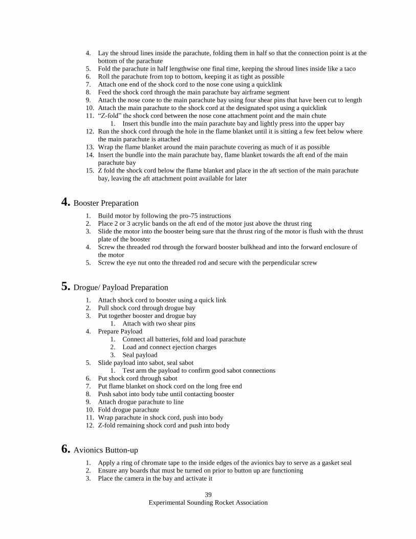
Experimental Sounding Rocket Association
39
4. Lay the shroud lines inside the parachute, folding them in half so that the connection point is at the
bottom of the parachute
5. Fold the parachute in half lengthwise one final time, keeping the shroud lines inside like a taco
6. Roll the parachute from top to bottom, keeping it as tight as possible
7. Attach one end of the shock cord to the nose cone using a quicklink
8. Feed the shock cord through the main parachute bay airframe segment
9. Attach the nose cone to the main parachute bay using four shear pins that have been cut to length
10. Attach the main parachute to the shock cord at the designated spot using a quicklink
11. “Z-fold” the shock cord between the nose cone attachment point and the main chute
1. Insert this bundle into the main parachute bay and lightly press into the upper bay
12. Run the shock cord through the hole in the flame blanket until it is sitting a few feet below where
the main parachute is attached
13. Wrap the flame blanket around the main parachute covering as much of it as possible
14. Insert the bundle into the main parachute bay, flame blanket towards the aft end of the main
parachute bay
15. Z fold the shock cord below the flame blanket and place in the aft section of the main parachute
bay, leaving the aft attachment point available for later
4. Booster Preparation 1. Build motor by following the pro-75 instructions
2. Place 2 or 3 acrylic bands on the aft end of the motor just above the thrust ring
3. Slide the motor into the booster being sure that the thrust ring of the motor is flush with the thrust
plate of the booster
4. Screw the threaded rod through the forward booster bulkhead and into the forward enclosure of
the motor
5. Screw the eye nut onto the threaded rod and secure with the perpendicular screw
5. Drogue/ Payload Preparation 1. Attach shock cord to booster using a quick link
2. Pull shock cord through drogue bay
3. Put together booster and drogue bay
1. Attach with two shear pins
4. Prepare Payload
1. Connect all batteries, fold and load parachute
2. Load and connect ejection charges
3. Seal payload
5. Slide payload into sabot, seal sabot
1. Test arm the payload to confirm good sabot connections
6. Put shock cord through sabot
7. Put flame blanket on shock cord on the long free end
8. Push sabot into body tube until contacting booster
9. Attach drogue parachute to line
10. Fold drogue parachute
11. Wrap parachute in shock cord, push into body
12. Z-fold remaining shock cord and push into body
6. Avionics Button-up 1. Apply a ring of chromate tape to the inside edges of the avionics bay to serve as a gasket seal
2. Ensure any boards that must be turned on prior to button up are functioning
3. Place the camera in the bay and activate it
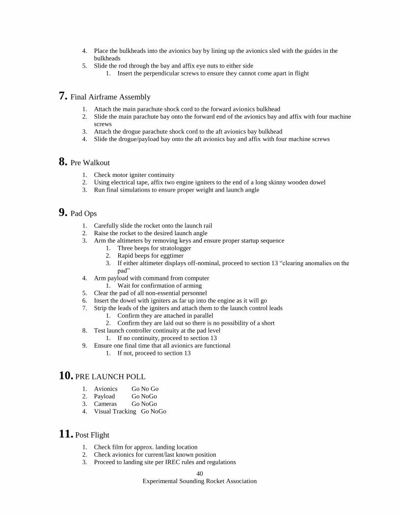
Experimental Sounding Rocket Association
40
4. Place the bulkheads into the avionics bay by lining up the avionics sled with the guides in the
bulkheads
5. Slide the rod through the bay and affix eye nuts to either side
1. Insert the perpendicular screws to ensure they cannot come apart in flight
7. Final Airframe Assembly 1. Attach the main parachute shock cord to the forward avionics bulkhead
2. Slide the main parachute bay onto the forward end of the avionics bay and affix with four machine
screws
3. Attach the drogue parachute shock cord to the aft avionics bay bulkhead
4. Slide the drogue/payload bay onto the aft avionics bay and affix with four machine screws
8. Pre Walkout 1. Check motor igniter continuity
2. Using electrical tape, affix two engine igniters to the end of a long skinny wooden dowel
3. Run final simulations to ensure proper weight and launch angle
9. Pad Ops 1. Carefully slide the rocket onto the launch rail
2. Raise the rocket to the desired launch angle
3. Arm the altimeters by removing keys and ensure proper startup sequence
1. Three beeps for stratologger
2. Rapid beeps for eggtimer
3. If either altimeter displays off-nominal, proceed to section 13 “clearing anomalies on the
pad”
4. Arm payload with command from computer
1. Wait for confirmation of arming
5. Clear the pad of all non-essential personnel
6. Insert the dowel with igniters as far up into the engine as it will go
7. Strip the leads of the igniters and attach them to the launch control leads
1. Confirm they are attached in parallel
2. Confirm they are laid out so there is no possibility of a short
8. Test launch controller continuity at the pad level
1. If no continuity, proceed to section 13
9. Ensure one final time that all avionics are functional
1. If not, proceed to section 13
10. PRE LAUNCH POLL 1. Avionics Go No Go
2. Payload Go NoGo
3. Cameras Go NoGo
4. Visual Tracking Go NoGo
11. Post Flight 1. Check film for approx. landing location
2. Check avionics for current/last known position
3. Proceed to landing site per IREC rules and regulations
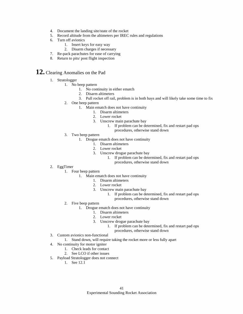
Experimental Sounding Rocket Association
41
4. Document the landing site/state of the rocket
5. Record altitude from the altimeters per IREC rules and regulations
6. Turn off avionics
1. Insert keys for easy way
2. Disarm charges if necessary
7. Re-pack parachutes for ease of carrying
8. Return to pits/ post flight inspection
12. Clearing Anomalies on the Pad 1. Stratologger
1. No beep pattern
1. No continuity in either ematch
2. Disarm altimeters
3. Pull rocket off rail, problem is in both bays and will likely take some time to fix
2. One beep pattern
1. Main ematch does not have continuity
1. Disarm altimeters
2. Lower rocket
3. Unscrew main parachute bay
1. If problem can be determined, fix and restart pad ops
procedures, otherwise stand down
3. Two beep pattern
1. Drogue ematch does not have continuity
1. Disarm altimeters
2. Lower rocket
3. Unscrew drogue parachute bay
1. If problem can be determined, fix and restart pad ops
procedures, otherwise stand down
2. EggTimer
1. Four beep pattern
1. Main ematch does not have continuity
1. Disarm altimeters
2. Lower rocket
3. Unscrew main parachute bay
1. If problem can be determined, fix and restart pad ops
procedures, otherwise stand down
2. Five beep pattern
1. Drogue ematch does not have continuity
1. Disarm altimeters
2. Lower rocket
3. Unscrew drogue parachute bay
1. If problem can be determined, fix and restart pad ops
procedures, otherwise stand down
3. Custom avionics non-functional
1. Stand down, will require taking the rocket more or less fully apart
4. No continuity for motor igniter
1. Check leads for contact
2. See LCO if other issues
5. Payload Stratologger does not connect
1. See 12.1
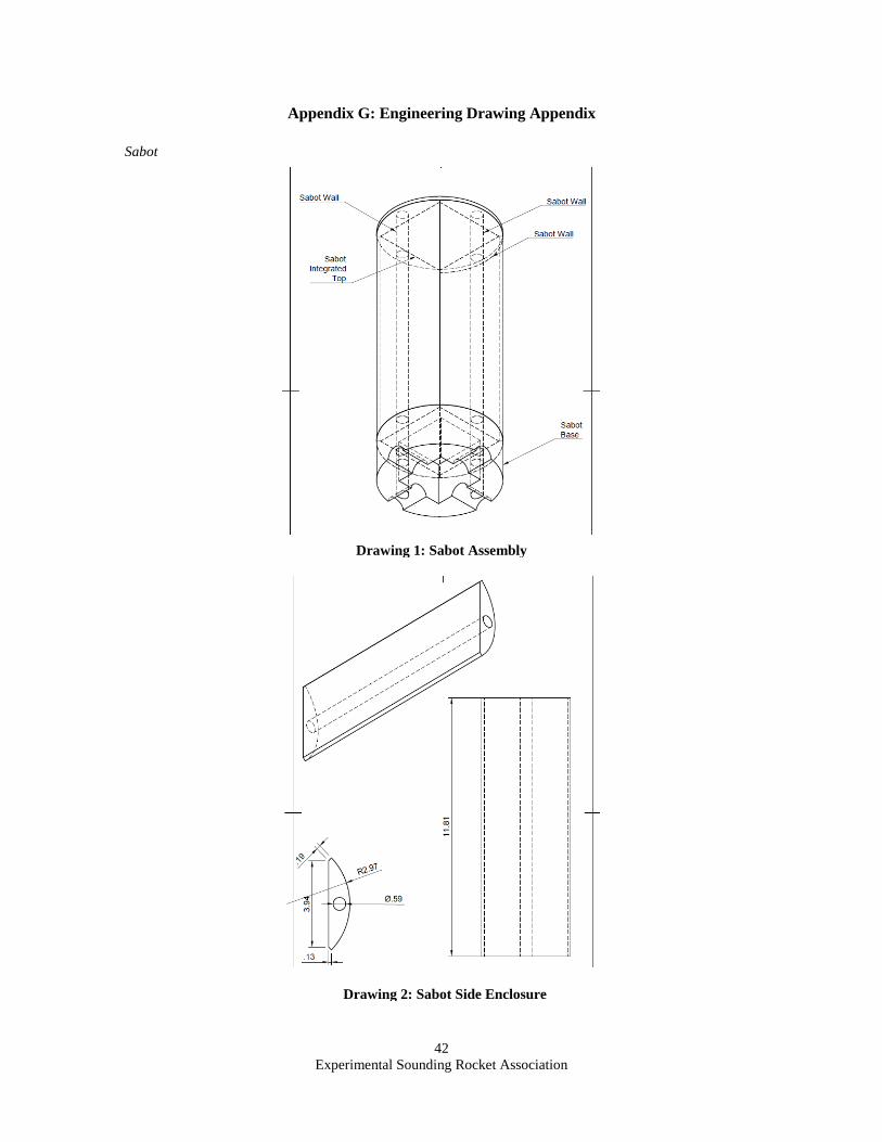
Experimental Sounding Rocket Association
42
Appendix G: Engineering Drawing Appendix
Sabot
Drawing 1: Sabot Assembly
Drawing 2: Sabot Side Enclosure
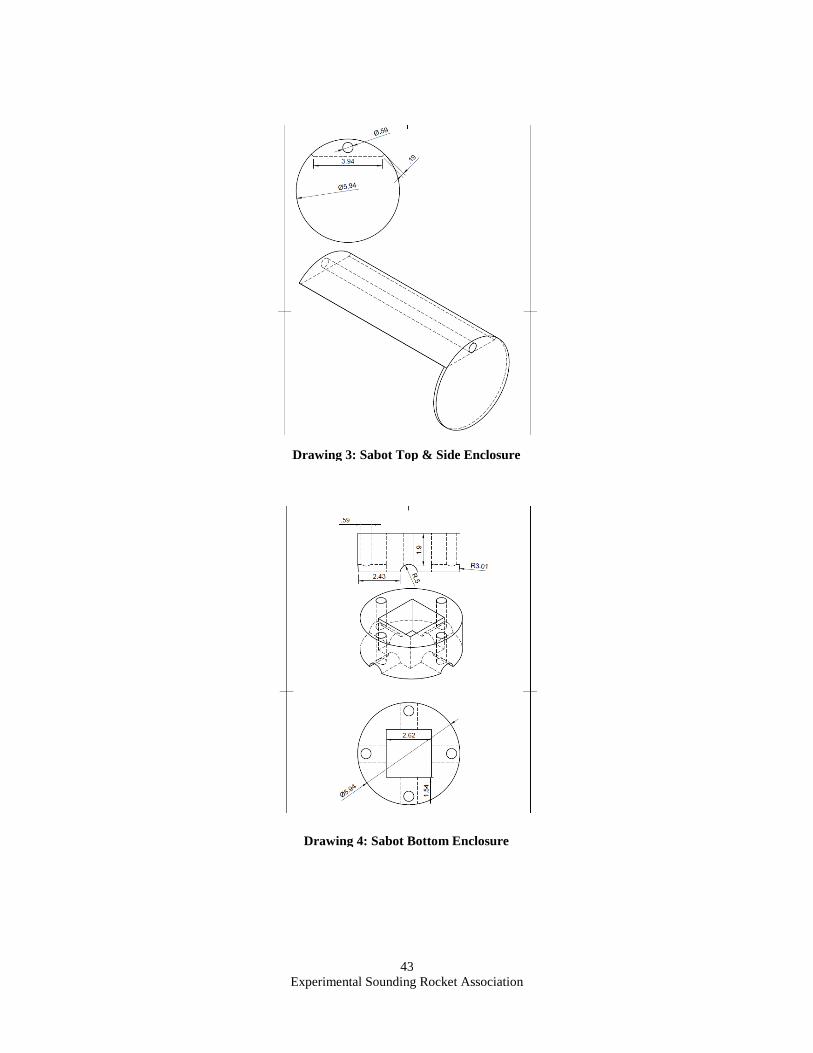
Experimental Sounding Rocket Association
43
Drawing 3: Sabot Top & Side Enclosure
Drawing 4: Sabot Bottom Enclosure
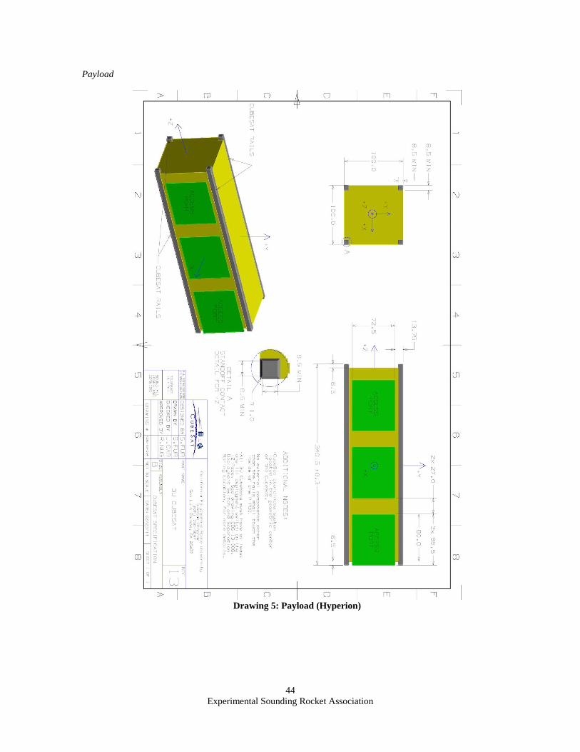
Experimental Sounding Rocket Association
44
Payload
Drawing 5: Payload (Hyperion)
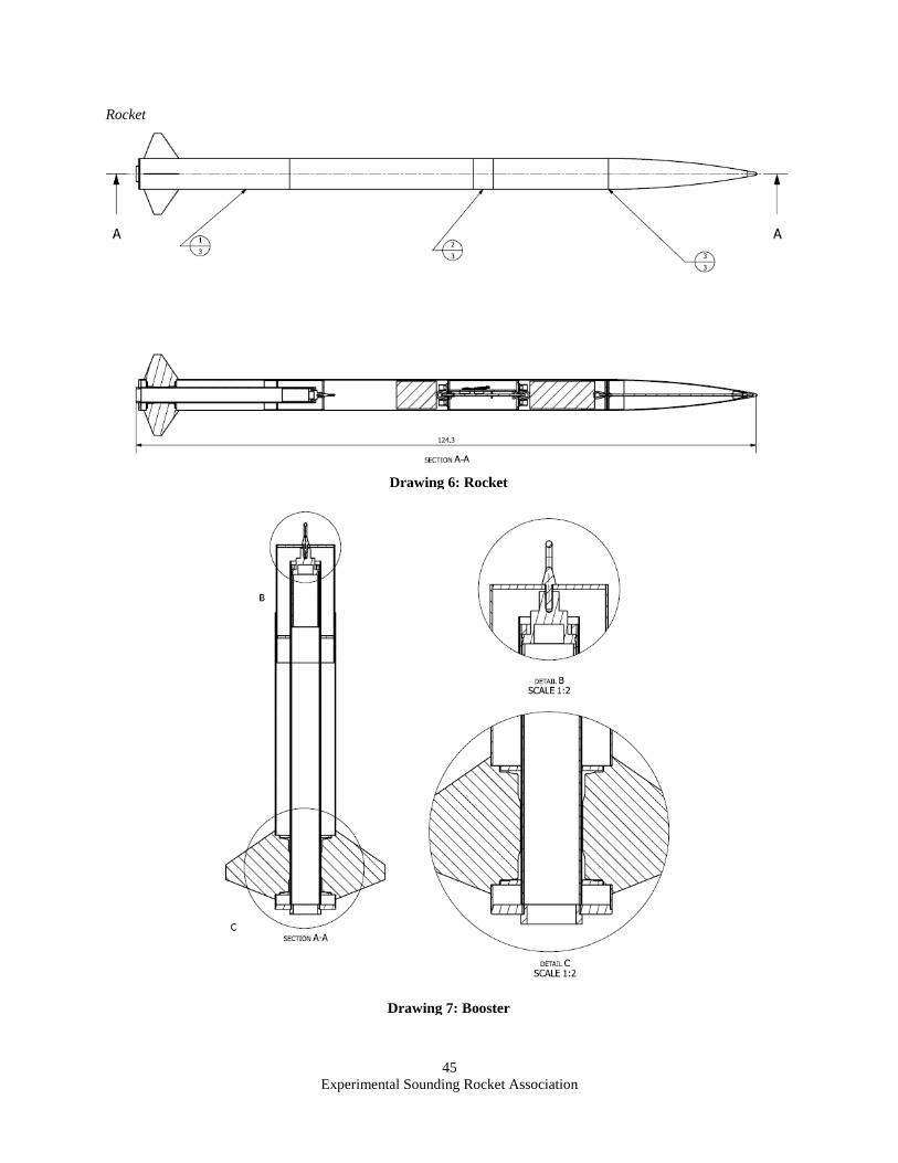
Experimental Sounding Rocket Association
45
Rocket
Drawing 6: Rocket
Drawing 7: Booster
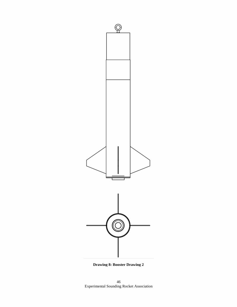
Experimental Sounding Rocket Association
46
Drawing 8: Booster Drawing 2
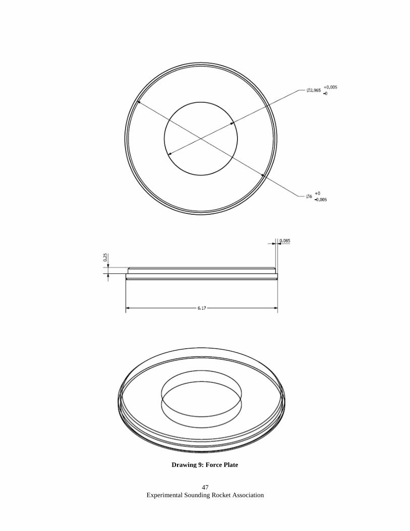
Experimental Sounding Rocket Association
47
Drawing 9: Force Plate
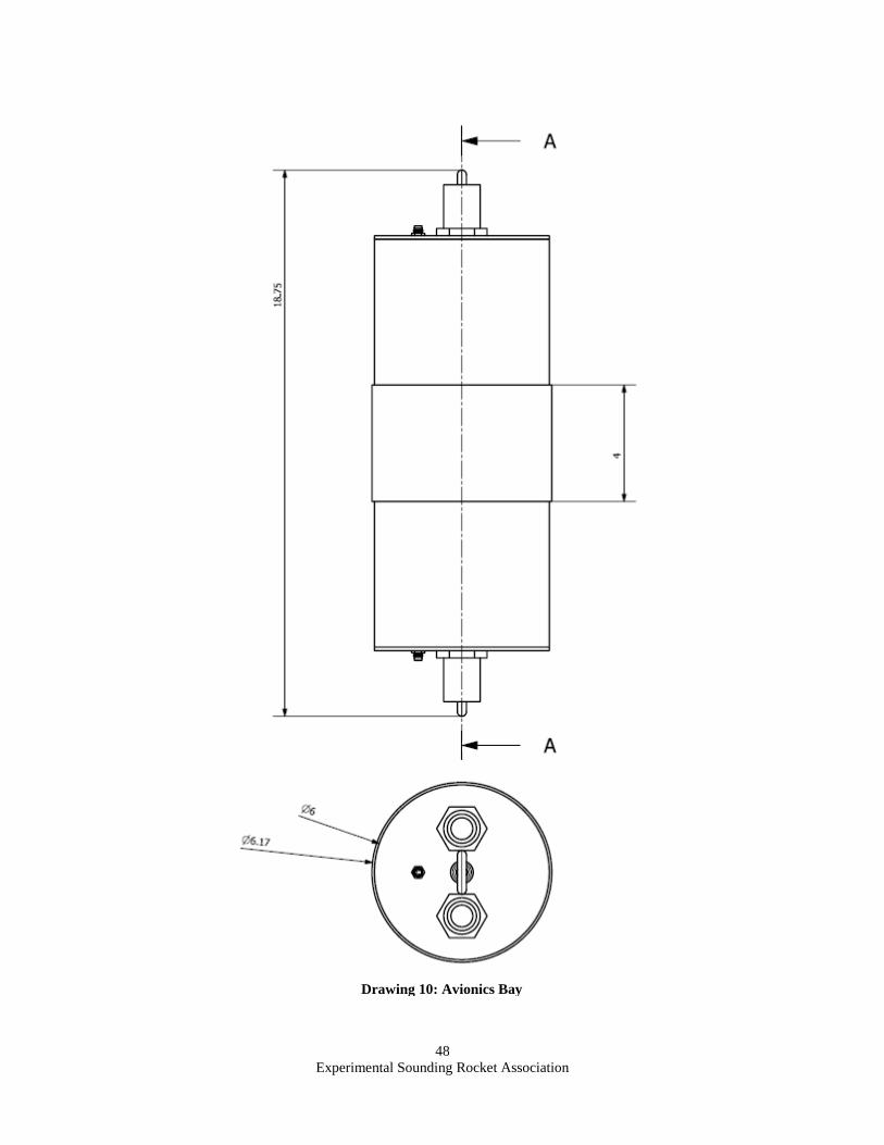
Experimental Sounding Rocket Association
48
Drawing 10: Avionics Bay
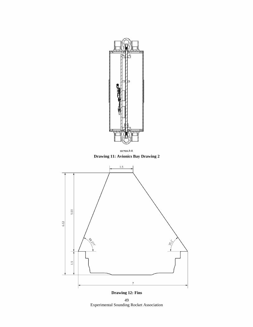
Experimental Sounding Rocket Association
49
Drawing 11: Avionics Bay Drawing 2
Drawing 12: Fins
Experimental Sounding Rocket Association
50
Acknowledgments
The authors would like to thank the following for their contributions to the project:
Michael Buffalin for supporting our team and providing the space and equipment necessary to successfully
complete the project.
Kate Gleason College of Engineering for supporting our first IREC competition and helping us complete all
the required school documentation.
Upstate Research Rocketry Group for providing experienced rocket knowledge, launch memberships, and a
launch site for our test launch.
All parties who donated to RIT LI’s crowdfunding campaign.
Team Members:
Daniel Mitchell for leading project Hyperion, including the electrical design for the payload.
James Parkus for leading the structural design and implementation of the payload.
Mark Saunders for designing the custom flight computer and ground station systems.
Hunter Collins for leading aerodynamic design and contributing to the manufacturing of the rocket.
Eric Roth for consulting and his contributions to launch operations.
Zoe Beepat for contributions to ejection charge logistics and flight computer setup.
Ivan Chukhryaev for contributions to the booster design and assembly.
Jim Heaney for leading sabot design and facilitating communications on payload design & integration.
Nick Foster for assisting in the design and production of the sabot system.
Pat Ekeren for modeling the optimum drogue and main parachute sizes.
Ben Richard for contributions to the analysis and design of recovery systems.
Justin Napieralski for leading the structural analysis and manufacturing of the booster.
Nick Krodthoff for contributions to the initial booster CAD model and assembly.
Jordan D’Alba for contributions to the final booster CAD model and assembly.
Justin Silva for the design, manufacturing, and tesing of the camera bay.
Bailey Reid for contributions to payload bay design and overall rocket manufacturing.
Dylan Bruenning for leading the aerostructural desing and analysis of the rocket.
Meagan Trabert for contributions to the camera bay.
All other parties who assisted and contributed to our team’s success this year.
References
Aluminum 6061-T6; 6061-T651 [Fact sheet]. (n.d.). Retrieved May 24, 2018, from
MATWEB website: http://www.matweb.com/search/
DataSheet.aspx?MatGUID=b8d536e0b9b54bd7b69e4124d8f1d20a&ckck=1
G-10 Fiberglass Epoxy Laminate Sheet [Fact sheet]. (n.d.). Retrieved May 24,
2018, from MATWEB website: http://www.matweb.com/search/
datasheet_print.aspx?matguid=8337b2d050d44da1b8a9a5e61b0d5f85
The CubeSat Program. (n.d.). In CubeSat Design Specification (13th ed., pp.
29-42). Los Angeles, CA: Cal Poly SLO.
Modules [Fact sheet]. (n.d.). Retrieved May 24, 2018, from AVR Libc website:
https://www.nongnu.org/avr-libc/user-manual/modules.html
Eggtime Rocketry, “Eggtimer Quark User’s Guide”,
URL: http://www.eggtimerrocketry.com/attachments/File/Eggtimer__Quark_Users__Guide.pdf

Experimental Sounding Rocket Association
51
"StratoLoggerCF Users Manual", URL: http://www.perfectflite.com/Downloads/StratoLoggerCF%20manual.pdf
Dean Wolf. "A Simplified Dynamic Model of Parachute Inflation", Journal of Aircraft, Vol. 11, No. 1 (1974),
pp. 28-33.
Smith, James Lee. “Hock Response Spectra Variational Analysis for Pyrotechnic Qualification Testing of Flight
Hardware.” Nasa.gov, NASA, 27 May 2018, ntrs.nasa.gov/archive/nasa/casi.ntrs.nasa.gov/19840015608.pdf.
“Aluminum 2024-T4; 2024-T351.” Overview of Materials for Polycarbonate, Extruded,
www.matweb.com/search/datasheet_print.aspx?matguid=67d8cd7c00a04ba29b618484f7ff7524.
Canepa, Mark B. Modern High-Power Rocketry 2. Trafford Publishing, 2005
Bernstein, I.M., and Donald Peckner. “MatWeb - The Online Materials Information
Resource.” Edited by Philip D. Harvey, Overview of Materials for Polycarbonate,
Extruded, www.matweb.com/search/datasheet.aspx?matguid=abc4415b0f8b4
90387e3c922237098da&ckck=1.
Boyer, Howard E., and Timothy L Gall. “Aluminum 6061-T6.” Overview of Materials for
Polycarbonate, Extruded, www.matweb.com/search/datasheet_print.aspx?mat
guid=1b8c06d0ca7c456694c7777d9e10be5b.
“DATA SHEET: G5000 HIGH STRENGTH EPOXY.” Glenmarc Industries Inc.
Apogee Components, “Mounting a video camera to your rocket,” Youtube [online web site], 10 May 2016, URL:
https://www.youtube.com/watch?v=kJD7rB61NoE [cited 27 May 2018]
Koslow, T., “PLA Filament Guide 2018,” All3DP [online web site], 17 April 2018, URL:
https://all3dp.com/1/pla-filament-3d-printing/ [cited 27 May 2018]
Locker, A., “PETG Filament Guide 2018 – Explained, Compared & Reviewed,” All3DP [online web site], 7
Mar. 2018, URL: https://all3dp.com/1/petg-filament-3d-printing/ [cited 27 May 2018]