these marks indicate that a product has successfully passed … · both spindle / anvil c0.2 330°...
TRANSCRIPT

B-37
B
Mitutoyo operates a policy of continuous improvement that aims to provide the customer with the benefit of the latest technological advances.Therefore the company reserves the right to change any or all aspects of any product specification without notice.
Technical DataFlatness: 0.6μm/.000024” for models with 150mm/6” throat 1μm/.00004” for models with 300mm/12” throatParallelism: 3μm/.00012”Quantizing error (389 series): excluding ±1 count
IP Codes (389 series)Level 6: Dust-proof. No ingress of dust allowed. Level 5: Protected against water jets. Water projected in jets against the enclosure from any direction shall have no harmful effects.
Optional accessories• Connecting cables for Series 389 (excluding 389-514 and 389-714) 1m: 05CZA662 2m: 05CZA663 • USB Input Tool Direct USB-ITN-B (2m): 06ADV380B • SPC cables for U-WAVE, 389 series (excluding 389-514 and 389-714) w/ data switch (160mm): 02AZD790B For foot switch: 02AZE140B• Connecting ccables for 389-514, 389-714 • Recommended cables: L-Type (does not interfere with
operating the thimble.) 1m: 04AZB512 2m: 05AZB513• Straight type (may interfere with operating the thimble.) 1m: 959149 2m: 959150
Refer to page A-21 for detailed information about recom-mended cables.
Battery for 389 seriesSR44 (1pc), 938882, 2pcs:389-514, 389-714 for initial operational checks (standard accessory)
L-type
Straight Type
Standard, Flat-Flat (F-F)
Spherical-Flat (S-F)
Spherical-Spherical (S-S)
These marks indicate that a product has successfully passed IP65-level testing, which is carried out by the independent German certification organization TÜV Rheinland.Micrometer
The origin of Mitutoyo’s trustworthy brand of small tool instruments
Sheet Metal MicrometersSERIES 389, 118
• Measures thickness of sheet metal. • IP65 water/dust protection (389 series).• Measuring faces: Carbide • Profile of measuring faces: Flat-Flat,
Spherical-Flat and Spherical-Spherical.
• Equipped with Ratchet Stop for constant measuring force.
DIMENSIONS Unit: mm
118-102
Order No. a b c d e f118-101 34 110
2.5 30 27.5 14.5118-102 118-114118-118
43 160
118-103 78 330 3.5 38.5 35 28118-110 41 165 2.5 55.3 27.5 14.5
389-514Analog models
389-251
SPECIFICATIONSMetric
Order No. Range Resolution Accuracy* Throat depth
Measuring surfaces
Digimatic (LCD)389-251
0 - 25mm
0.001mm
±4μm 150mmF-F
389-261 S-F389-271 S-S389-514 ±5μm 300mm*1
F-F389-25225 - 50mm ±4μm 150mm389-262 S-F
389-272 S-S* Excluding quantizing error
Metric
Order No. Range Graduation Accuracy Throat depth
Measuring surfaces
Analog118-101
0 - 25mm0.01mm
±4μm
100mm F-F118-102150mm118-114 S-F
118-118 S-S118-103 ±5μm 300mm* F-F118-110 25 - 50mm ±4μm 150mm118-126 S-S
*1 Models with a 300mm (12") throat are equipped with a stand for convenience of measurement in the horizontal orientation as standard.
Inch/Metric
Order No. Range Resolution Accuracy* Throat depth
Measuring surfaces
Digimatic (LCD)389-351
0 - 1".00005"/0.001mm
±.0002" 6"F-F
389-361 S-F389-371 S-S389-714 ±.00025" 12"*1
F-F389-3521"- 2" ±.0002" 6"389-362 S-F
389-372 S-S* Excluding quantizing error
Inch
Order No. Range Graduation Accuracy Throat depth
Measuring surfaces
Analog118-129
0 - 1" .0001" ±.0002" 6"F-F
118-116 S-F118-120 S-S118-107 .001" ±.00025" 12" F-F118-112 1"- 2" ±.0002" 6"
dac e
f
ø6.3
5(ø
8)
b
ø9.7
ø18
(ø21
)
( ): Order No.118-103
353.578 38.5 28
ф8
330
ф21
2 55.3 3 50 17
(スピンドル・アンビル共)C0.2
330°
スタンド
353.
578
38.5
28
ø8
330
ø21
255
.33
5017
Both Spindle / Anvil C0.2
330°
Stand Stand
ø9.7
(Refer to page IX for details.)

B-38
B
Mitutoyo operates a policy of continuous improvement that aims to provide the customer with the benefit of the latest technological advances.Therefore the company reserves the right to change any or all aspects of any product specification without notice.
Sheet Metal MicrometerSERIES 119
• Large diameter dial model enables easy and quick measurement of sheet metal thickness.
• Adjustable anvil.• Measuring faces: Carbide
• Equipped with Ratchet Stop for constant measuring force.
DIMENSIONS
Unit: mm
119-202
SPECIFICATIONSMetric
Order No. Range Graduation Accuracy Throat depth119-202 0 - 25mm 0.01mm ±4μm 50mm
SR20(Anvil)
403714.5 419 17
ø6.3
5
27.52.5
506
ø60
ø19 ø9
.7

B-39
B
Mitutoyo operates a policy of continuous improvement that aims to provide the customer with the benefit of the latest technological advances.Therefore the company reserves the right to change any or all aspects of any product specification without notice.
MicrometerThe origin of Mitutoyo’s trustworthy brand of small tool instruments
IP Codes (395 series)Level 6: Dust-proof. No ingress of dust allowed. Level 5: Protected against water jets. Water projected in jets against the enclosure from any direction shall have no harmful effects.
Technical Data Flatness: 0.6μm/ .000024” (115 & 295 Series) 0.3μm/ .000012” (395 Series)
Optional accessories Connecting cables for 395 series 1m: 05CZA662 2m: 05CZA663USB Input Tool Direct USB-ITN-B (2m): 06ADV380BConnecting cables for U-WAVE-T 02AZD790B 160mm For foot switch: 02AZE140B Refer to page A-21 for details.
Tube MicrometersSERIES 395, 115, 295
• Measuring faces: Carbide (115-101: only the spindle is carbide tipped.)• 395 series: IP65 digital spherical-flat anvil
type micrometer.
• Equipped with Ratchet Stop for constant measuring force.
DIMENSIONS
Unit: mm
5 øD
SR4
Unit: mm
0
45
5
19 14.5 33.517.8
15.5
19
ø9.7
37
ø6.3
5
171.2
ø3
1.2
SR2
ø15
Battery for series 395SR44 (1 pc), 938882, for initial operational checks (standard accessory)
These marks indicate that a product has successfully passed IP65-level testing, which is carried out by the independent German certification organization TÜV Rheinland.
395-251
115-115
SPECIFICATIONSMetricOrder No. Range Resolution Accuracy* øD
Digimatic (LCD)395-251 0 - 25mm
0.001mm ±2μm ø15395-252 25 - 50mm395-253 50 - 75mm ø19395-254 75 - 100mm ±3μm ø20
* Excluding quantizing error
MetricOrder No. Range Graduation Accuracy øD
Analog115-101 0 - 15mm
0.01mm
±3μm
ø5.5115-115 0 - 25mm ø10115-116 25 - 50mm ø11115-117 50 - 75mm ø17115-118 75 - 100mm ±4μm ø18
Mechanical counter model295-115 0 - 25mm ±3μm ø10
Inch/MetricOrder No. Range Resolution Accuracy* øD
Digimatic (LCD)395-351 0 - 1"
.00005"/0.001mm
±.0001" ø.59"395-352 1" - 2"395-353 2" - 3" ø.75"395-354 3" - 4" ±.00015"
* Excluding quantizing error
InchOrder No. Range Graduation Accuracy øD
Analog115-153 0 - 1" .0001" ±.00015" ø.40"
Mechanical counter model295-153 0 - 1" .0001" ±.00015" ø.40"
115-101
(Refer to page IX for details.)

B-40
B
Mitutoyo operates a policy of continuous improvement that aims to provide the customer with the benefit of the latest technological advances.Therefore the company reserves the right to change any or all aspects of any product specification without notice.
These marks indicate that a product has successfully passed IP65-level testing, which is carried out by the independent German certification organization TÜV Rheinland.
Tube Micrometers SERIES 395, 115, 295 — Spherical Anvil and Spindle Type
• Measuring faces: Carbide (115-201: only the spindle is carbide tipped.)• 395 series: IP65 spherical anvil and spindle
type digital micrometer.
• Equipped with Ratchet Stop for constant measuring force.
DIMENSIONS
Unit: mm
395-271
0
45
5
19 14.5 33.517.8
15.5
19.5
ø9.7
37
ø6.3
5
171.2
ø15
SR4
ø1
SR1
Details of the measuring unit
1.2
4 4
(94)
(42.
5)
115-201
Inch/MetricOrder No. Range Resolution Accuracy* øD
Digimatic (LCD)395-371 0 - 1"
.00005"/0.001mm
±.0001" ø.59"395-372 1" - 2"395-373 2" - 3" ø.75"395-374 3" - 4" ±.00015" ø.79"
* Excluding quantizing error
InchOrder No. Range Graduation Accuracy øD
Analog115-253 0 - 1" .0001"
±.00015"ø.40"
115-242 1 - 2" .001" ø.44"115-243 2 - 3" ø.67"
Mechanical counter model295-253 0 - 1" .0001" ±.00015" ø.40"
SPECIFICATIONSMetricOrder No. Range Resolution Accuracy* øD
Digimatic (LCD)395-271 0 - 25mm
0.001mm ±2μm ø15395-272 25 - 50mm395-273 50 - 75mm ø19395-274 75 - 100mm ±3μm ø20
* Excluding quantizing error
MetricOrder No. Range Graduation Accuracy øD
Analog115-201 0 - 15mm
0.01mm ±3μm
ø5.5115-215 0 - 25mm ø10115-216 25 - 50mm ø11115-217 50 - 75mm ø17115-218 75 - 100mm ±4μm ø18
Mechanical counter model295-215 0 - 25mm 0.01mm ±3μm ø10
115-215
IP Codes (395 series)Level 6: Dust-proof. No ingress of dust allowed. Level 5: Protected against water jets. Water projected in jets against the enclosure from any direction shall have no harmful effects.
Optional accessories Connecting cables for 395 series 1m: 05CZA662 2m: 05CZA663USB Input Tool Direct USB-ITN-B (2m): 06ADV380BConnecting cables for U-WAVE-T 02AZD790B 160mm For foot switch: 02AZE140B Refer to page A-21 for details.
5 øD
SR4 SR4
Unit: mm
Battery for series 395SR44 (1 pc), 938882, for initial operational checks (standard accessory)
(Refer to page IX for details.)

B-41
B
Mitutoyo operates a policy of continuous improvement that aims to provide the customer with the benefit of the latest technological advances.Therefore the company reserves the right to change any or all aspects of any product specification without notice.
MicrometerThe origin of Mitutoyo’s trustworthy brand of small tool instruments
Tube MicrometersSERIES 395, 115, 295 — Spherical and Cylindrical Anvil Type
• Spindle face: Carbide • 395 Series: IP65 spherical and cylindrical anvil
type digital micrometers
• Equipped with Ratchet Stop for constant measuring force.
These marks indicate that a product has successfully passed IP65-level testing, which is carried out by the independent German certification organization TÜV Rheinland.
395-261
SPECIFICATIONSMetricOrder No. Range Resolution Accuracy* Remarks
Digimatic (LCD)395-261
0 - 25mm 0.001mm ±3μm
Type A395-262 Type B395-263 Type C395-264 Type D
* Excluding quantizing error
MetricOrder No. Range Graduation Accuracy Remarks
Analog115-302 0 - 25mm
0.01mm ±3μm
Type A115-308 Type B115-303 25 - 50mm Type A115-309 Type B115-315 0 - 25mm Type C115-316 Type D
Inch/MetricOrder No. Range Resolution Accuracy* Remarks
Digimatic (LCD)395-362
0 - 1" .00005"/0.001mm ±.00015"
Type B395-363 Type C395-364 Type D
* Excluding quantizing error
InchOrder No. Range Graduation Accuracy Remarks
Analog115-305
0 - 1".001"
±.00015"Type A
115-313 .0001" Type C115-314 Type D
IP Codes (395 series)Level 6: Dust-proof. No ingress of dust allowed. Level 5: Protected against water jets. Water projected in jets against the enclosure from any direction shall have no harmful effects.
Optional accessories Connecting cables for 395 series 1m: 05CZA662 2m: 05CZA663USB Input Tool Direct USB-ITN-B (2m): 06ADV380BConnecting cables for U-WAVE-T 02AZD790B 160mm For foot switch: 02AZE140B Refer to page A-21 for details.
Type B (spherical)Type A (pin)
Type C (cylindrical) Type D (cylindrical)
Unit: mm
Type C (cylindrical) Type D (cylindrical)
øD
LD: Minimum measurable inside diameterL : Distance to spindle center
ø8
ø4ø6.9ø6.9
12.7
Sø4.7ø3.5
68
ø1.8
9
ø8
ø4ø6.9ø6.9
12.7
Sø4.7ø3.5
68
ø1.8
9Battery for series 395SR44 (1 pc), 938882, for initial operational checks (standard accessory)
Anvil D LType A 2 4Type B 3.6Type C 4.8 12Type D 8.2 22
Type A (pin) Type B (spherical)
(Refer to page IX for details.)

B-42
B
Mitutoyo operates a policy of continuous improvement that aims to provide the customer with the benefit of the latest technological advances.Therefore the company reserves the right to change any or all aspects of any product specification without notice.
These marks indicate that a product has successfully passed IP65-level testing, which is carried out by the independent German certification organization TÜV Rheinland.
Spline Micrometers SERIES 331, 111, 131
• The anvil and spindle are of small diameter for measuring splined shafts, slots, and keyways.
• IP65 water/dust protection (series 331).
• Measuring faces: Carbide • Equipped with Ratchet Stop for constant
measuring force.
331-251
111-115
Inch/MetricOrder No. Range Resolution Accuracy* Remarks
Digimatic (LCD)331-351 0 - 1"
.00005"/0.001mm
±.0001" Type A331-352 1" - 2"331-353 2" - 3"331-354 3" - 4" ±.00015"331-361 0 - 1"
±.0001" Type B331-362 1" - 2"331-363 2" - 3"331-364 3" - 4" ±.00015"
* Excluding quantizing error
InchOrder No. Range Graduation Accuracy Remarks
Analog111-166 0 - 1" .0001" ±.00015" Type A
SPECIFICATIONSMetricOrder No. Range Resolution Accuracy* Remarks
Digimatic (LCD)331-251 0 - 25mm
0.001mm
±2μm Type A331-252 25 - 50mm331-253 50 - 75mm331-254 75 - 100mm ±3μm331-261 0 - 25mm
±2μm Type B331-262 25 - 50mm331-263 50 - 75mm331-264 75 - 100mm ±3μm
* Excluding quantizing error
MetricOrder No. Range Graduation Accuracy Remarks
Analog111-215 0 - 25mm
0.01mm
±3μm
Type B111-115 0 - 25mm
Type A
111-116 25 - 50mm111-117 50 - 75mm111-118 75 - 100mm
±4μm111-119 100 - 125mm111-120 125 - 150mm111-121 150 - 175mm
±5μm111-122 175 - 200mm111-123 200 - 225mm111-124 225 - 250mm
±6μm111-125 250 - 275mm111-126 270 - 300mm
Mechanical counter model131-115 0 - 25mm ±3μm Type A
IP Codes (331 series)Level 6: Dust-proof. No ingress of dust allowed. Level 5: Protected against water jets. Water projected in jets against the enclosure from any direction shall have no harmful effects.
Technical DataFlatness: 0.3μm/ .000012” Parallelism: (2+R/100)μm, R = max. range (mm) [.00008” + .00004(R/4)]” R = max range (inch) fraction rounded down
Optional accessories Connecting cables for 331 series 1m: 05CZA662 2m: 05CZA663USB Input Tool Direct USB-ITN-B (2m): 06ADV380BConnecting cables for U-WAVE-T 02AZD790B 160mm For foot switch: 02AZE140B Refer to page A-21 for details.
10 10 55
ø3 ø2
Type A ø3mm Type B ø2mm
Unit: mmUnit: mm
Battery for series 331SR44 (1 pc), 938882, for initial operational checks (standard accessory)
(Refer to page IX for details.)

B-43
B
Mitutoyo operates a policy of continuous improvement that aims to provide the customer with the benefit of the latest technological advances.Therefore the company reserves the right to change any or all aspects of any product specification without notice.
MicrometerThe origin of Mitutoyo’s trustworthy brand of small tool instruments
DIMENSIONS
Unit: mm
Models up to 75mm measuring range
Digital Models
Models over 75mm measuring range
Models up to 300mm measuring range
Range a b c d0 - 25mm 7.3 32
17.558.2
25 - 50mm 10.1 47 83.250 - 75mm 11.5 60 108.2
Digital Models
Analog Models
174714.5Lb
37.5a
3
ø 6.3
5
c
ø 18
5
0
45
C
32.342.5 43 17
ø 6.35
L
ø 9.7
ba 40.7
ø 6.3
5
16.7
ø 9.7
20.3 37.5
76
132.8 174332.347.2214.5ø 1
8
ø 18
174714.5da
37.5c
3
ø 6.3
5
b
ø 18
5
0
45
b
32.342.5 43 17
ø 6.3
5
d
ø 9.7
a
c 40.7
ø 6.3
5
a
ø 9.7
c 37.5
b
d 174332.347.2214.5ø 1
8
ø 18
ø 9.7
174714.5da
37.5c
3
ø 6.3
5
b
ø 18
5
0
45
b
32.342.5 43 17
ø 6.3
5
d
ø 9.7
a
c 40.7
ø 6.3
5
a
ø 9.7
c 37.5
b
d 174332.347.2214.5ø 1
8
ø 18
ø 9.7
Range a b c d0 - 25mm 10 38
17.555
25 - 50mm 12 49 8050 - 75mm 14 60 105
75 - 100mm 16.7 79 20.3 132.8100 - 125mm 18.8 94 20.7 158.2125 - 150mm 19.1 106 21.1 183.6150 - 175mm 18.2 118 21.3 208.8175 - 200mm 16.8 130 21.7 234.2200-225mm
18
18121.5
334225-250mm 169 309250-275mm 156 284275-300mm 143 20.5 258

B-44
B
Mitutoyo operates a policy of continuous improvement that aims to provide the customer with the benefit of the latest technological advances.Therefore the company reserves the right to change any or all aspects of any product specification without notice.
These marks indicate that a product has successfully passed IP65-level testing, which is carried out by the independent German certification organization TÜV.
Point Micrometers SERIES 342, 142, 112
• Pointed spindle and anvil for measuring the web thickness of drills, small grooves, keyways, and other hard-to-reach features.
• The measuring points (carbide tipped) have approximately 0.3mm radius.
• 342 series: IP65 Digimatic micrometers • Equipped with Ratchet Stop for constant
measuring force.
342-251
Inch/MetricOrder No. Range Resolution Accuracy* Point
Digimatic (LCD) (With carbide tip)342-351 0 - 1"
.00005"/0.001mm
±.0001"15º
342-352 1 - 2"342-353 2 - 3"342-354 3 - 4" ±.00015"342-361 0 - 1"
±.0001"30º
342-362 1 - 2"342-363 2 - 3"342-364 3 - 4" ±.00015"
* Excluding quantizing error
InchOrder No. Range Graduation Accuracy Point
Analog112-177 0 - 1"
.001"
±.00015"15º112-178 1" - 2"
112-225 0 - 1" 30º112-226 1" - 2"Analog (With carbide tip)
112-189 0" - 1"
±.00015"15º112-190 1" - 2"
112-191 2" - 3"112-237 0 - 1" 30º112-238 1" - 2"
Mechanical counter model142-177 0 - 1" ±.00015" 15º142-225 30º
SPECIFICATIONSMetricOrder No. Range Resolution Accuracy* Point
Digimatic (LCD) (With carbide tip)342-251 0 - 25mm
0.001mm
±2μm15º
342-252 25 - 50mm342-253 50 - 75mm342-254 75 - 100mm ±3μm342-261 0 - 25mm
±2μm30º
342-262 25 - 50mm342-263 50 - 75mm342-264 75 - 100mm ±3μm
* Excluding quantizing error
MetricOrder No. Range Graduation Accuracy Point
Analog112-153 0 - 25mm
0.01mm
±3μm 15º112-154 25 - 50mm112-155 50 - 75mm112-156 75 - 100mm ±4μm112-201 0 - 25mm
±3μm 30º112-202 25 - 50mm112-203 50 - 75mm112-204 75 - 100mm ±4μm
Analog (With carbide tip)112-165 0 - 25mm
±3μm 15º112-166 25 - 50mm112-167 50 - 75mm112-168 75 - 100mm ±4μm112-213 0 - 25mm
±3μm 30º112-214 25 - 50mm112-215 50 - 75mm112-216 75 - 100mm ±4μm
Mechanical counter model142-153 0 - 25mm ±3μm 15º142-201 30º
IP Codes (342 series)Level 6: Dust-proof. No ingress of dust allowed. Level 5: Protected against water jets. Water projected in jets against the enclosure from any direction shall have no harmful effects.
Technical Data
Optional accessories Connecting cables for 342 series 1m: 05CZA662 2m: 05CZA663 USB Input Tool Direct USB-ITN-B (2m): 06ADV380B SPC cables for U-WAVE w/ data switch (160mm): 02AZD790B For foot switch: 02AZE140B (Refer to page A-21 for details.)
Tip angle: 15º
Tip angle: 30º
Battery for 342 seriesSR44 (1 pc), 938882, for initial operational checks (standard accessory)
112-201
(Refer to page IX for details.)

B-45
B
Mitutoyo operates a policy of continuous improvement that aims to provide the customer with the benefit of the latest technological advances.Therefore the company reserves the right to change any or all aspects of any product specification without notice.
MicrometerThe origin of Mitutoyo’s trustworthy brand of small tool instruments
DIMENSIONS
Unit: mmDigital models up to 75mm measuring range
Analog models measuring range
Digital models over 75mm measuring range
15° type 30° type
15°
(SR0.3)
30°
(SR0.3)
10 10
174714.5da
42.5c
3
ø 6.3
5
ø 18
b
b
φ9.
7
L
φ6.
35
174342.5 2.3 3
c
a 45.7
φ6.
35
φ18
b
φ9.
7
a 42.5
c
L 174332.347.2214.5
φ18
(70.3)
7
(11.2)
(25)
25
(57.96)
9.4
(13)
(20.8)
ø 9.7
Order No. a b c d Frame thickness*1
342-2517.3 32
12.5
58.2 (11.2)342-261342-252
10.1 47 83.2 (12.8)342-262342-253
11.5 60 108.2 (12.8)342-263342-254
16.7 76 15.3 132.8 (20.8)342-264112-153 10 38
12.555 (9)
112-154 12 49 80 (10)112-155 14 60 105 (11)112-156 17 79 15.3 132.8 (13)
*1 Digimatic type: thickness over heat shield
45.7c
(25)
b
32.342.5 43 17
ø 18
ø 6.3
5
d
ø 9.7
a
7
(25)
c
(70
.3)
(11.2)
14.5 2 47.2 2.3 3 43 17d
b
42.5c
ø 9.7
a
(25)
ø 18
ø 6.3
5

B-46
B
Mitutoyo operates a policy of continuous improvement that aims to provide the customer with the benefit of the latest technological advances.Therefore the company reserves the right to change any or all aspects of any product specification without notice.
V-Anvil Micrometers SERIES 314, 114 — 3 Flutes and 5 Flutes
• Measures the outside diameter of cutting tools (such as taps, reamers, end mills) which have three or five flutes.
• Measures pitch diameter: refer to “Quick Guide to Precision Measuring Instruments” on page B-72.
• Measuring faces: Carbide• Equipped with Ratchet Stop for constant
measuring force.
Anvil
Tap
WireSpindle
Pitch Diameter Measurement of Tapby Single-wire Method
114-102
114-101
314-251-10
114-121
Battery for 314 series SR44 (1 pc), 938882, for initial operational checks (standard accessory)
Optional accessories Connecting cables for 314 series 1m: 05CZA662 2m: 05CZA663 USB Input Tool Direct USB-ITN-B (2m): 06ADV380B SPC cables for U-WAVE w/ data switch (160mm): 02AZD790B For foot switch: 02AZE140B (Refer to page A-21 for details.)

B-47
B
Mitutoyo operates a policy of continuous improvement that aims to provide the customer with the benefit of the latest technological advances.Therefore the company reserves the right to change any or all aspects of any product specification without notice.
MicrometerThe origin of Mitutoyo’s trustworthy brand of small tool instruments
DIMENSIONS
Unit: mm
SPECIFICATIONSMetric For 3-flute cutting toolsOrder No. Range Resolution Accuracy* Remarks Anvil
Digimatic (LCD) 314-251-10 1 - 15mm
0.001mm
±4μm w/groove
60º314-252-10 10 - 25mm314-253-10 25 - 40mm ±5μm —314-261-10 1 - 15mm ±4μm —314-262-10 10 - 25mm —
*Excluding quantizing errorMetric For 3-flute cutting toolsOrder No. Range Graduation Accuracy Remarks Anvil
Analog Anvil, Spindle (With carbide tip)114-204 2.3 - 25mm
0.01mm
±4μm —
60º
Analog Spindle (With carbide tip)114-101 1 - 15mm ±4μm w/groove114-102 10 - 25mm114-103 25 - 40mm ±5μm —114-104 40 - 55mm ±6μm —114-105 55 - 70mm —114-106 70 - 85mm ±7μm —114-161 1 - 15mm ±4μm —114-162 10 - 25mm —
Metric For 5-flute cutting toolsOrder No. Range Resolution Accuracy Remarks Anvil
Analog Anvil, Spindle (With carbide tip)114-137 2.3 - 25mm
0.01mm
±4μm —
108º
Analog Spindle (With carbide tip)114-121 5 - 25mm ±4μm w/groove114-122 25 - 45mm ±5μm —114-123 45 - 65mm ±6μm —114-124 65 - 85mm ±7μm —114-165 5 - 25mm ±4μm —
Inch/Metric For 3-flute cutting toolsOrder No. Range Resolution Accuracy* Remarks Anvil
Digimatic (LCD) 314-351-10 .05 - .6"
.00005"/0.001mm
±.0002" w/groove
60º314-352-10 .4" - 1"314-353-10 1" - 1.6" ±.00025" —314-361-10 .05 - .6" ±.0002" —314-362-10 .4" - 1" —
*Excluding quantizing errorInch For 3-flute cutting toolsOrder No. Range Graduation Accuracy Remarks Anvil
Analog Spindle (With carbide tip)114-163 .05" - 6" .0001" ±.0002" — 60º114-113 1" - 1.6" ±.00025" —
Inch For 5-flute cutting toolsOrder No. Range Graduation Accuracy Remarks Anvil
Analog Spindle (With carbide tip)114-135 .09" - 1" .0001" ±.0002" — 108º
Range (a)
10 - 25mm 6.225 - 40mm 19.1440 - 55mm 32.1355 - 70mm 45.1270 - 85mm 58.11
w/o groove model
w/ groove model
For 3-flute cutting tools
47 173
ø 18
14.5
ø 6.3
5
27.5
18
60°
114-103
(a)
ø 9.7
9
12
AA View on arrow
(14.7)
0.5
(14.5)
60°
8
ø1.5
8
ø1.5
22.7
(23.
46)
ø6.3
560
°
30.3
114-101 114-204
6.78
A
A View on arrow

B-48
B
Mitutoyo operates a policy of continuous improvement that aims to provide the customer with the benefit of the latest technological advances.Therefore the company reserves the right to change any or all aspects of any product specification without notice.
Blade Micrometers SERIES 422, 122 — Non-Rotating Spindle Type
• The anvil and spindle are blade-shaped for measuring the groove diameter of shafts, keyways, and other hard-to-reach features.
• Carbide-tipped measuring faces are also available.
• Non-rotating spindle type.• Equipped with Ratchet Stop for constant
measuring force.
Quickmike Type (LCD)422-411
Digimatic (LCD)422-230
122-101
Inch/Metric Order No. Range Resolution Accuracy* Remark
Digimatic (LCD)422-330 0 - 1"
.00005"/0.001mm
±.00015"Type A
422-331 1" - 2"422-332 2" - 3"422-333 3" - 4" ±.0002"422-360
0 - 1" ±.00015"Type B
422-370 Type C422-371 Type D
* Excluding quantizing error
Inch/Metric Quickmike typeOrder No. Range Resolution Accuracy* Remark
Digimatic (LCD)
422-421 0 - 1.2" .00005"/0.001mm ±.00015" Type A
* Excluding quantizing error
InchOrder No. Range Graduation Accuracy Remark
Analog122-125 0 - 1"
.0001"
±.00015"Type A
122-126 1" - 2"122-127 2" - 3"122-128 3" - 4" ±.0002"122-135
0 - 1" ±.00015"Type B
122-151 Type D
SPECIFICATIONSMetric
Order No. Range Resolution Accuracy* RemarkDigimatic (LCD)422-230 0 - 25mm
0.001mm
±3μm Type A422-231 25 - 50mm422-232 50 - 75mm422-233 75 - 100mm ±4μm422-260 0 - 25mm
±3μmType B422-261 25 - 50mm
422-270 0 - 25mm Type C422-271 Type D
* Excluding quantizing error
Metric Quickmike typeOrder No. Range Resolution Accuracy* RemarkDigimatic (LCD)422-411 0 - 30mm 0.001mm ±3μm Type A422-412 25 - 55mm
* Excluding quantizing error
MetricOrder No. Range Graduation Accuracy RemarkAnalog122-101 0 - 25mm
0.01mm
±3μm
Type A
122-102 25 - 50mm122-103 50 - 75mm122-104 75 - 100mm
±4μm122-105 100 - 125mm122-106 125 - 150mm122-107 150 - 175mm
±5μm122-108 175 - 200mm122-109 200 - 225mm122-110 225 - 250mm
±6μm122-115 250 - 275mm122-116 275 - 300mm122-111 0 - 25mm 0.01mm ±3μm Type B122-112 25 - 50mm
Analog (With carbide tip)122-161 0 - 25mm 0.01mm
±3μmType C122-162 25 - 50mm
122-141 0 - 25mm 0.01mm Type D122-142 25 - 50mmNotes: 1) A heat shield is provided with Digimatic models and 422-230 as standard.
Technical DataParallelism3μm/ .0012” for models up to 75mm/ 3”(3+R/100)μm for models over 75mm, R = max. range (mm)fraction rounded up.00016” for 4” models
Type and Dimensions Type A Type B
Type C (carbide-tipped)
Type D (carbide-tipped)
Battery for 422 seriesSR44 (1 pc), 938882, for initial operational checks (standard accessory)
Optional accessories Connecting cables for digital models 1m: 05CZA662 2m: 05CZA663 USB Input Tool Direct USB-ITN-B (2m): 06ADV380B Connecting cables for U-WAVE-T (digital models) 02AZD790B (160mm) For foot switch: 02AZE140BConnecting cables for Quickmike type 1m: 937387 2m: 965013USB Input Tool Direct USB-ITN-E (2m): 06ADV380EConnecting cables for U-WAVE-T (Quickmike type) 02AZD790E 160mm For foot switch: 02AZE140E Refer to page A-21 for details.
Quickmike Provides a speedy spindle feed of 10mm per thimble rotation, which enables widely differently sized features to be measured quickly.
Deviation between the Anvil and Spindle in the Vertical Direction
Unit: mm Unit: mm
Unit: mm Unit: mm
6.5
ø 6
0.75R8
6
0.75
0.4R8
36.5
6
ø 6
ø 6
0.75
711
60°
6
60°
ø 6
0.4
48
6
Deviation of 0.15mm or less is guaranteed between the anvil and spindle in the vertical direction.
within 0.15mmDeviation between the anvil and spindle in the vertical direction
* When the measuring range is 0 - 25mm

B-49
B
Mitutoyo operates a policy of continuous improvement that aims to provide the customer with the benefit of the latest technological advances.Therefore the company reserves the right to change any or all aspects of any product specification without notice.
MicrometerThe origin of Mitutoyo’s trustworthy brand of small tool instruments
DIMENSIONS
Unit: mmDigital models up to 50mm measuring range
Range a b C d0 - 25mm 7.8 32 15 55.3
ab
53.113.5
cd 42.5
14.2
2.3 3 41 11.5 17
ø18
ø14
ø6.3
5ø6
ø9.7
13.5
41 11.5 1732.347.26.514.541.8
dc
a
ø 18
ø 6.3
5ø 6
b
ø 9.7
a
ø 6.3
5ø 6
b
ø 24.
9
d 69.6 3.3 42.9 4.2c
40.33 47 15.514.5d
b ø12
ø9.7ø6 ø8
ø18
17ac
1715.54714.5da40.3c
3
ø 8ø 6
b ø 18
ø 9.7
Range a b C d0 - 25mm 11 31 12.5 65.6
25 - 50mm 12.2 50 12.6 90.7
Range a b C d50 - 75mm 14.6 57 13 104.8
75 - 100mm 16.7 76 16 132.8
Range a b C d0 - 30mm 8.5 36 13.5 59.8
25 - 55mm 10.3 47 84.8
Range a b C d25 - 50mm 12.2 49 14.5 79.850 - 75mm 14.6 60 104.8
75 - 100mm 17 79 17.5 132.8100 - 125mm 19 94 17.9 158.2125 - 150mm 20 106 18.3 183.6150 - 175mm 19 118 18.5 208.8175 - 200mm 17 130 18.9 234.2200 - 225mm
18
143 17.7 258225 - 250mm 156
18.7284
250 - 275mm 169 309275 - 300mm 181 334
Analog models measuring range
Digital models over 75mm measuring range
Quickmike type

B-50
B
Mitutoyo operates a policy of continuous improvement that aims to provide the customer with the benefit of the latest technological advances.Therefore the company reserves the right to change any or all aspects of any product specification without notice.
Can Seam Micrometers SERIES 147
• Measures the width, height, and depth of can seams.
DIMENSIONS
Unit: mm
InchOrder No. Range Graduation Accuracy Remarks147-104
0 - .5" .001” ±.00015"for steel cans
147-106 for aluminum cans147-201 for spray cans
SPECIFICATIONSMetric
Order No. Range Graduation Accuracy Remarks147-103
0 - 13mm 0.01mm ±3μmfor steel cans
147-105 for aluminum cans147-202 for spray cans
147-103
Technical Data
35.5 1.5 32.5
40° 147-201, 147-202
147-103, 147-104
147-105, 147-106
10 15 1.5
8.1
6.1
35.5 1.5 47 5
7.5
ø5
ø5
ø6
ø6
6.1
15 SR0.3 x 40° 10
ø5
ø6
8.1 1.5
2
35.5 1.5 47
6.15
15
45°
0.5 10
7 1.3
1.5
ø13.
7
ø13
Zero point adjustment
Zero point adjustment
Zero point adjustment
ø13.
7
ø13
ø13
ø13.
7
147-103147-104
147-105147-106
147-202 147-201
for steel cans(for depth measurements up to 5mm)
for aluminum cans
for spray cans
B-51
B
Mitutoyo operates a policy of continuous improvement that aims to provide the customer with the benefit of the latest technological advances.Therefore the company reserves the right to change any or all aspects of any product specification without notice.
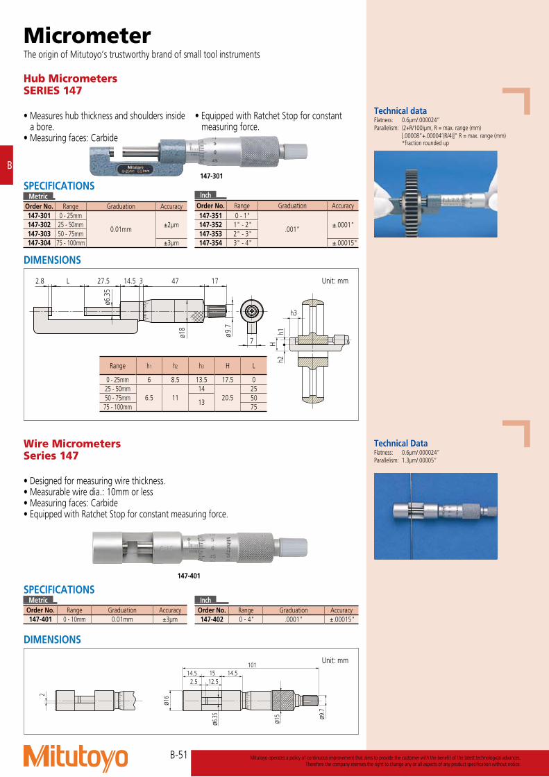
Wire MicrometersSeries 147
• Designed for measuring wire thickness.• Measurable wire dia.: 10mm or less• Measuring faces: Carbide• Equipped with Ratchet Stop for constant measuring force.
DIMENSIONS
Unit: mm
Technical Data Flatness: 0.6μm/.000024”Parallelism: 1.3μm/.00005”
147-401
MicrometerThe origin of Mitutoyo’s trustworthy brand of small tool instruments
14.5101
15 14.512.52.5
ø16
ø15
ø6.3
5
2
ø9.7
SPECIFICATIONSMetric
Order No. Range Graduation Accuracy147-401 0 - 10mm 0.01mm ±3μm
InchOrder No. Range Graduation Accuracy147-402 0 - 4" .0001” ±.00015"
Hub MicrometersSERIES 147
• Measures hub thickness and shoulders inside a bore.
• Measuring faces: Carbide
• Equipped with Ratchet Stop for constant measuring force.
DIMENSIONS
Unit: mm
h3
h1h2
H
InchOrder No. Range Graduation Accuracy147-351 0 - 1"
.001”±.0001"147-352 1" - 2"
147-353 2" - 3"147-354 3" - 4" ±.00015"
SPECIFICATIONSMetric
Order No. Range Graduation Accuracy147-301 0 - 25mm
0.01mm±2μm147-302 25 - 50mm
147-303 50 - 75mm147-304 75 - 100mm ±3μm
147-301
Range h1 h2 h3 H L
0 - 25mm 6 8.5 13.5 17.5 025 - 50mm
6.5 1114
20.525
50 - 75mm13
5075 - 100mm 75
Technical data Flatness: 0.6μm/.000024” Parallelism: (2+R/100)μm, R = max. range (mm) [.00008”+.00004’(R/4)]” R = max. range (mm) *fraction rounded up
3 4714.527.5L2.8
7
17
ø18
ø6.3
5
ø9.7

B-52
B
Mitutoyo operates a policy of continuous improvement that aims to provide the customer with the benefit of the latest technological advances.Therefore the company reserves the right to change any or all aspects of any product specification without notice.
DIMENSIONS
Unit: mm
Crimp Height Micrometers Series 342,112,142
• Measures the height of crimp contacts.• Equipped with Ratchet Stop for constant
measuring force.• IP65 water/dust protection (digital model).
• Model 342-451 is the Quickmike type, which provides a speedy spindle feed of 10mm per thimble rotation, which enables widely differently sized features to be measured quickly.
No.342-271
ø 9.7
2.5 30.717
25
ø 6.3
5
42.5 2.3 3 4333.26.5
5
0
45
A
60°
ø 0.50.5
2.8
2-C0.5
A View on arrow
ø 18
Quickmike type (LCD)342-451
Digimatic (LCD)342-271
112-401
Inch/MetricOrder No. Range Resolution Accuracy*
Digimatic (LCD)342-371 0 - .8" .00005"/ 0.001mm ±.00015"
* Excluding quantizing error
MetricOrder No. Range Graduation Accuracy
Analog112-401 0 - 25mm 0.01mm ±3μm
SPECIFICATIONSMetricOrder No. Range Resolution Accuracy*
Digimatic (LCD)342-271 0 - 20mm 0.001mm ±3μm
Quickmike (LCD)342-451 0 - 15mm 0.001mm ±3μm
* Excluding quantizing errorMetricOrder No. Range Graduation Accuracy
Mechanical counter model142-402
0 - 25mm0.01mm
±3μm142-403 0.001mm
IP Codes (342-271, 371 series)Level 6: Dust-proof. No ingress of dust allowed. Level 5: Protected against water jets. Water projected in jets against the enclosure from any direction shall have no harmful effects.
Optional accessories Connecting cables (digital model) 1m: 05CZA662 2m: 05CZA663 USB Input Tool Direct USB-ITN-B (2m): 06ADV380B Connecting cables for U-WAVE-T (digital model) 02AZD790B (160mm) For foot switch: 02AZE140BConnecting cables (Quickmike type) 1m: 937387 2m: 965013USB Input Tool Direct USB-ITN-E (2m): 06ADV380EConnecting cables for U-WAVE-T (Quickmike type) 02AZD790E 160mm For foot switch: 02AZE140E Refer to page A-21 for details.
Battery for 342 series SR44 (1 pc), 938882, for initial operational checks (standard accessory)
342-271, 342-371, 112-401
ø0.5
60° 0.5
Unit: mm
342-451
ø0.5
45° 0.75
Unit: mm
142-402, 142-403
ø0.6
27° 1
Unit: mm
These marks indicate that a product has successfully passed IP65-level testing, which is carried out by the independent German certification organization TÜV Rheinland.
(Refer to page IX for details.)

B-53
B
Mitutoyo operates a policy of continuous improvement that aims to provide the customer with the benefit of the latest technological advances.Therefore the company reserves the right to change any or all aspects of any product specification without notice.
”Uni-Mike”Series 317, 117 — Interchangeable Anvil Type
• Measures tubing thickness, shoulder-edge distance, rivet head height, etc., with interchangeable anvils (flat anvil, rod anvil, V-anvil).
• IP65 water/dust protection (317 series).• Equipped with Ratchet Stop for constant
measuring force.
DIMENSIONS
Unit: mm
1.5 52.5 (27.5)25 (0) 27.5
34 26.5
7
25
33.6
8.5
ø6.35
ø18
117-102( ): for 0-25mm measuring range model
ø9.7
MicrometerThe origin of Mitutoyo’s trustworthy brand of small tool instruments
These marks indicate that a product has successfully passed IP65-level testing, which is carried out by the independent German certification organization TÜV Rheinland.
317-251
117-101
SPECIFICATIONSMetric Order No. Range Resolution Accuracy*
Digimatic (LCD)317-251 0 - 25mm 0.001mm ±4μm317-252 25 - 50mm
* Excluding quantizing error
MetricOrder No. Range Graduation Accuracy
Analog117-101 0 - 25mm 0.01mm ±4μm117-102 25 - 50mm
Inch/Metric Order No. Range Resolution Accuracy*
Digimatic (LCD)317-351 0 - 1" .00005"/ 0.001mm ±.0002"317-352 1" - 2"
* Excluding quantizing error
InchOrder No. Range Graduation Accuracy
Analog117-107 0 - 1" .0001" ±.0002"117-108 1" - 2"
IP Codes (317 series)Level 6: Dust-proof. No ingress of dust allowed. Level 5: Protected against water jets. Water projected in jets against the enclosure from any direction shall have no harmful effects.
Technical dataFlatness: Spindle face 0.6μm Anvil face 2μmParallelism: 3μm
Optional accessoriesConnecting cables (317 series) 1m: 05CZA662 2m: 05CZA663 USB Input Tool Direct USB-ITN-B (2m): 06ADV380B Connecting cables for U-WAVE-T 02AZD790B 160mm For foot switch: 02AZE140B Refer to page A-21 for details.
1.5120° 6.35
25
ø3 (for 25mm)ø5 (for 50mm)
Rod anvil(Standard accessory)
Flat anvil(Standard accessory)
V-anvil(optional)
Unit: mmR3.2
Accessories
Battery for 317 series SR44 (1 pc), 938882, for initial operational checks (standard accessory)
Order No. Item 201216 Flat anvil (standard accessory)201217 Rod anvil (standard accessory for 117-101)201379 Rod anvil (standard accessory for 117-102)201218 V-anvil (optional)950758 Base for 25mm (optional)
(Refer to page IX for details.)

B-54
B
Mitutoyo operates a policy of continuous improvement that aims to provide the customer with the benefit of the latest technological advances.Therefore the company reserves the right to change any or all aspects of any product specification without notice.
Limit Micrometers SERIES 113
• Dual-spindle design enables use as a GO/±NG gage by setting upper and lower limits.
• Measuring faces: Carbide
Unit: mm
113-102
a d1.8 27.5
C0.5(each spindle
& anvil)
ø6.3
5
19.5
b
14.5
ø18
SPECIFICATIONSMetric
Order No. Range Graduation Accuracy Flatness Parallelism113-102 0 - 25mm
0.01mm ±3μm 0.6μm 3μm113-103 25 - 50mm
Range a b d0 - 25mm
1523 29.3
25 - 50mm 37 54.3

B-55
B
Mitutoyo operates a policy of continuous improvement that aims to provide the customer with the benefit of the latest technological advances.Therefore the company reserves the right to change any or all aspects of any product specification without notice.
MicrometerThe origin of Mitutoyo’s trustworthy brand of small tool instruments
Technical DataFlatness: 0.3μm/.000012”Parallelism: 0.6μm/ .000024” for models up to 50mm/ 2” 1μm/ .00004” for models over 50mm/ 2” Accuracy: ±2μmSpindle feed error: 3μm/ .00015”Dispersion of indication: 0.4μm/ .00002”Dial indication accuracy: 1μm/ .00005”
Workpiece stop (optional)Realizes more stable measurement. Three types are available to suit workpieces of different sizes.
Unit: mm
Dmin: Minimum measurable diameterDmax: Maximum measurable diameterC: Distance from the center of the workpiece to the upper surface of the workpiece stop
A
B4
6
C
Dmin
Dmax
Range A BWorkpiece stop A
04AZA124 ø16 23
Workpiece stop B04AZA125 ø14 20.5
Workpiece stop C04AZA126 ø14 15
Order No 510-121, 510-141, 510-131, 510-151 Unit: mmDmin Dmax C
Workpiece stop A N/A N/A N/AWorkpiece stop B 4 16 5.0Workpiece stop C 15 25 10.5
510-122 and 510-132Dmin Dmax C
Workpiece stop A 25 37 15.5Workpiece stop B 30 42 18.0Workpiece stop C 41 50 23.5
510-123 and 510-133Dmin Dmax C
Workpiece stop A 50 61 27.5Workpiece stop B 54 66 30.0Workpiece stop C 65 75 35.5
510-124 and 510-134Dmin Dmax C
Workpiece stop A 75 87 40.5Workpiece stop B 80 92 43.0Workpiece stop C 91 100 48.2
Indicating Micrometers SERIES 510
• Suited to the measurement of low-volume manufactured parts.
• Easy to use when operating one-handed due to retractable anvil.
• In the 25mm measuring range, the model lineup offers a choice of left or right positioning of the anvil-retraction button.
• Greatly improved accuracy: indication error and graduation of 1μm.
• Water-proof to protection level IP54.• Hard-coated crystal: enhanced oil and scratch
resistance.• Indicator scale is large and easy-to-read. • The zero position and adjustable limit
markers, for GO/±NG testing, are easily set.• Measuring faces: Carbide
DIMENSIONS Unit: mmUp to 25mm measuring range (anvil-retraction button on the right side)
Up to 25mm measuring range (anvil-retraction button on the left side)
Over 50mm measuring range (anvil-retraction button on the left side)
510-121
510-141
SPECIFICATIONSMetricOrder No. Range Indicating range Graduation Dial graduation Measuring force Anvil retraction button Mass510-121 0 - 25mm
±0.06mm 0.001mm 0.001mm 5 - 10N
Right side 520g510-141
Left side 530g
510-122 25 - 50mm 670g510-123 50 - 75mm 820g510-124 75 - 100mm 970g
InchOrder No. Range Indicating range Graduation Dial graduation Measuring force Anvil retraction button Mass510-131 0 - 1"
±.0023" .0001" .00005" 5 - 10N
Right side 520g 510-151
Left side 530g
510-132 1" - 2" 670g510-133 2" - 3" 820g510-134 3" - 4" 970g
Range b d t0 - 25mm 25 31.5 16.4
25 - 50mm 38 56.51650 - 75mm 50 81.5
75 - 100mm 63 106.5
(Refer to page IX for details.)
10
30
40 40
50 5060 60
10
30
0.001 mm000000
4505
5045
000000mm0.001
30
10
60605050
4040
3020
10
d
bb
3.550319
ø8
d11.555.5
55.5 11.5Range 31.5
19 3 50 3.5
ø21ø8
Retractable anvil button
Heat shieldThickness: t
Retractable anvil button
Workpiece stop (optional)
ø21
Workpiece stop (optional)
5045
000000mm0.001
30
10
60605050
4040
3020
10 b
3.550319
ø8
d11.555.5
Retractable anvil button Heat shieldThickness: t
Heat shieldThickness: t
ø21
Workpiece stop (optional)
10
30
40 40
50 5060 60
10
30
0.001 mm000000
4505
5045
000000mm0.001
30
10
60605050
4040
3020
10
d
bb
3.550319
ø8
d11.555.5
55.5 11.5Range 31.5
19 3 50 3.5
ø21ø8
Retractable anvil button
Heat shieldThickness: t
Retractable anvil button
Workpiece stop (optional)
ø21
Workpiece stop (optional)
5045
000000mm0.001
30
10
60605050
4040
3020
10 b
3.550319
ø8
d11.555.5
Retractable anvil button Heat shieldThickness: t
Heat shieldThickness: t
ø21
Workpiece stop (optional)

B-56
B
Mitutoyo operates a policy of continuous improvement that aims to provide the customer with the benefit of the latest technological advances.Therefore the company reserves the right to change any or all aspects of any product specification without notice.
Dial Snap MetersSERIES 523
• Suited to the measurement of mass-produced parts.
• Designed for measurement using a stand: realizes stable measurement.
• Greatly improved accuracy: indication error and graduation of 1μm.
• Water-proof to protection level IP54.• Hard-coated crystal: enhanced oil and scratch
resistance.
• Indicator scale is large and easy-to-read.• Easily settable adjustable limit markers for
GO/±NG testing. • Equipped with an elevating workpiece stop
as standard.• Measuring faces: Carbide
DIMENSIONS
Unit: mm
ø10.
8 Range15
b
89.5 d 11.5 69.5
Work-stopper
Anvil retraction button
SPECIFICATIONSMetric
Order No. Range Dial graduation Measuring force Mass523-121 0 - 25mm
0.001mm 5 - 10N
740g523-122 25 - 50mm 840g523-123 50 - 75mm 950g523-124 75 - 100mm 1080g
InchOrder No. Range Dial graduation Measuring force Mass523-131 0 - 1"
.00005" 5 - 10N
740g 523-132 1" - 2" 840g523-133 2" - 3" 950g523-134 3" - 4" 1080g
523-121
Range b d0 - 25mm 25 31
25 - 50mm 35 5650 - 75mm 47 81
75 - 100mm 60 106
Technical DataIndicator Indicating range: ±0.06mm/±.0023” Repeatability of indication: 0.4μm/.00002” Dial indication accuracy: 1μm/.00005”Flatness: 0.3μm/.000012”Parallelism: 0.6μm/.000024” for models up to 50mm/2” measuring range 1μm/.00004” for models over 50mm/2” measuring range
(Refer to page IX for details.)

B-57
B
Mitutoyo operates a policy of continuous improvement that aims to provide the customer with the benefit of the latest technological advances.Therefore the company reserves the right to change any or all aspects of any product specification without notice.
Snap Meters SERIES 523
• Suited to the measurement of mass-produced parts.
• Various types of indicator can be selected according to the measurement application.
• Measuring faces: Carbide
DIMENSIONS
Unit: mm
523-141(Indicator: optional)
AccuracyFlatness: 0.3μm/.000012”Parallelism: 0.6μm/.000024” for models up to 50mm/2” 1μm/.00004” for models over 50mm/2” Repeatability of indication: 0.4μm/.00002”
Typical Indicators used with gageID-C (0.001mm)/ 543-390BLGF-L (0.0001mm)/ 542-181 & Counter 542-015
MicrometerThe origin of Mitutoyo’s trustworthy brand of small tool instruments
ABS Digimatic Indicator
Linear Gage and counter
optionWork-stopper
Range
Dial
indica
tor h
olding
diam
eter
88.811.5d
bø1
0.8
ø8+0
.015
0
ø16
89.5
SPECIFICATIONSMetric
Order No. Range Anvil movement Measuring force* Mass523-141 0 - 25mm
2mm 5 - 10N
710g523-142 25 - 50mm 810g523-143 50 - 75mm 920g523-144 75 - 100mm 1050g
InchOrder No. Range Anvil movement Measuring force* Mass523-151 0 - 1"
.078" 5 - 10N
710g 523-152 1" - 2" 810g523-153 2" - 3" 920g523-154 3" - 4" 1050g
* Measured at the position where the anvil is retracted by 1mm from the free position without installing the indicator.
Range b d0 - 25mm 25 31
25 - 50mm 35 5650 - 75mm 47 81
75 - 100mm 60 106

B-58
B
Mitutoyo operates a policy of continuous improvement that aims to provide the customer with the benefit of the latest technological advances.Therefore the company reserves the right to change any or all aspects of any product specification without notice.
Groove MicrometersSERIES 146
• Flanged spindle and anvil for measuring width and location of grooves inside bores and tubes.
• Two-directional ratchet stop.• For ID and OD (except for 0 - 25mm)
measurement, a master gage is required for adjusting the reference point.
Flanges (measuring faces)
L ( )25 (103.3)50 (78.3)75 (53.3)
100 (28.3)
L ( )25 (115)50 (90)75 (65)
100 (40)
146-121
146-122
146-221
146-222
SPECIFICATIONSMetricOrder No. Range Outside Range Inside Graduation Accuracy Flange
Rotating spindle146-121 0 - 25mm 1.6 - 26.5mm
0.01mm ±10μm
ø6.35mm146-122
ø12.7mm146-123 25 - 50mm 26.5 - 51.5mm146-124 50 - 75mm 51.5 - 76.5mm146-125 75 - 100mm 76.5 - 101.5mm
MetricOrder No. Range Outside Range Inside Graduation Accuracy Flange
Non-rotating spindle146-221 0 - 25mm 1.6 - 26.5mm
0.01mm ±10μm
ø6.35mm146-222
ø12.7mm146-223 25 - 50mm 26.5 - 51.5mm146-224 50 - 75mm 51.5 - 76.5mm146-225 75 - 100mm 76.5 - 101.5mm
InchOrder No. Range Outside Range Inside Graduation Accuracy Flange
Rotating spindle146-131 0 - 1" .055" - 1.05"
.0001" ±.0004"
ø.25"146-132
ø.5"146-133 1" - 2" 1.05" - 2.05"146-134 2" - 3" 2.05" - 3.05"146-135 3" - 4" 3.05" - 4.05"
InchOrder No. Range Outside Range Inside Graduation Accuracy Flange
Non-rotating spindle146-231 0 - 1" .055" - 1.05"
.0001" ±.0004"
ø.25"146-232
ø.5"146-233 1" - 2" 1.05" - 2.05"146-234 2" - 3" 2.05" - 3.05"146-235 3" - 4" 3.05" - 4.05"
DIMENSIONS
Unit: mm
Technical dataParallelism: 10μm/.0004”
146-121
ø15ø10ø5
ø6.3
5ø3
.5
ø6.3
5
17473329.5(35)0.75
250.75
GVM-25SNR
(194)
φ6.
35
0.750.75
25 (35) 19.5
φ3.
5
φ6.
35 φ5
332 1761
φ10
φ15
φ18
.3
GVM-25NR
1761
φ15φ10
332(115)0.75
250.75
φ12
.7
(254.5)
φ6.
35
φ12
.7
φ18
.3
146-122, 146-123, 146-124, 146-125
(ℓ) 32 3 47
ø12.
7
ø6.3
5
ø12.
7
ø10
17
(228.8)
ø15
0.750.75
L
ø18
ø18 ø9
.7
ø9.7
φ18
(34.5)25 17473
ø5 ø15ø10
3219.50.75
0.75
ø3.5
ø6.3
5
ø6.3
5
ø18 ø9.7
146-221
L
ø12.
7
ø6.3
5
ø12.
7
0.75 0.75 32
ø10
ø15
3 47 17(ℓ)
ø18 ø9.7
146-222, 146-223, 146-224, 146-225

B-59
B
Mitutoyo operates a policy of continuous improvement that aims to provide the customer with the benefit of the latest technological advances.Therefore the company reserves the right to change any or all aspects of any product specification without notice.
MicrometerThe origin of Mitutoyo’s trustworthy brand of small tool instruments
Quick-MiniSERIES 700
• Lightweight and palm-sized.• Highly suitable for quick dimensional
inspection of small, thin and delicate objects. • Functions: origin setting and zero-setting.
• Application examples Measurement of small objects: pearls, jewels, shims for engine tappets
and screws. Measurement of thin objects: printing paper, polyethylene bags,
sheet materials, foods including noodles, lenses for glasses, media substrates, foils, thin plates and medical products including filter cloths.
Measurement of fine lines and bars: fishing lines, dental reamers, pasta, drills for PCB and hard wiring.
DIMENSIONS
Unit: mm
29
3523
.5
ø5
(44
.8)
206
3.857.
2
11
(72.3)166
29
35
23.5
ø5
(44
.8)
206
3.857.
211
(72.3)166
700-119-20
SPECIFICATIONSMetric
Order No. Range Resolution Accuracy* Mass700-119-20 0 - 12mm 0.01mm ±0.02 70 g
* Excluding quantizing errorInch/Metric
Order No. Range Resolution Accuracy* Mass700-118-20 0"- 5"/ 0 - 12mm .0005"/0.01mm ±.001" 70 g
* Excluding quantizing error
700-119-20
Technical DataSR44 (1 pc), 938882, for initial operational checks (standard accessory)

B-60
B
Mitutoyo operates a policy of continuous improvement that aims to provide the customer with the benefit of the latest technological advances.Therefore the company reserves the right to change any or all aspects of any product specification without notice.
Telescoping Gage Set SERIES 155
• A spring-loaded plunger expands within a bore (or groove) and is locked in place, allowing measurement of diameter (or width) with an outside micrometer after extraction.
Small Hole Gage SetSERIES 154
• Extra long for gaging deep and shallow holes, slots, and similar workpiece features.
• Two sprung leaves are fully expanded inside a feature so that its size can be measured with an outside micrometer after extraction.
154-902
SPECIFICATIONSMetric
Order No. Range4-gage Set
154-902 3 - 13mmGages included
154-101 3 - 5mm154-102 5 - 7.5mm154-103 7.5 - 10mm154-104 10 - 13mm
SPECIFICATIONSMetric
Order No. Range6-gage Set
155-905 8 - 150mmGages included
155-127 8 - 12.7mm155-128 12.7 - 19mm155-129 19 - 32mm155-130 32 - 54mm155-131 54 - 90mm155-132 90 - 150mm
InchOrder No. Range
4-gage Set154-901 .125" - .5"
Gages included154-105 .125" - .2"154-106 .2 - .3"154-107 .3 - .4"154-108 .4 - .5"
InchOrder No. Range
6-gage Set155-903 .313" - 6"
Gages included155-121 .313" - .5"155-122 .5 - .75"155-123 .75- 1.25"155-124 1.25 - 2.125"155-125 2.125 - 3.5"155-126 3.5 - 6"
DIMENSIONS Unit: mm
67L
øD
Clamp
ød1
Range ød1 L øD3 - 5mm 2.8 - 5.2 90
5.5 22.55 - 7.5mm 4.8 - 7.8 97.6 30
7.5 - 10mm 7.3 - 10.3 108 8.5 4010 - 13mm 9.8 - 13.2
DIMENSIONS Unit: mm
L
ød2
ød1
Clamp
øD
Range L øD ød1 ød2
8 - 12.7mm110
5 4 312.7 - 19mm 5.5 5 3.519 - 32mm32 - 54mm
150 8 7.5 654 - 90mm90 - 150mm
155-905

B-61
B
Mitutoyo operates a policy of continuous improvement that aims to provide the customer with the benefit of the latest technological advances.Therefore the company reserves the right to change any or all aspects of any product specification without notice.
MicrometerThe origin of Mitutoyo’s trustworthy brand of small tool instruments
SPECIFICATIONS and DIMENSIONS
Setting Standards for Outside Micrometers SERIES 167
• Used for adjusting the reference point of the outside micrometer.
167-103
167-108
167-101 – 167-103167-141 – 167-143
167-104 – 167-107167-144 – 167-147
167-108 – 167-119167-148 – 167-159
Unit: mm
Unit: mm
Unit: mm
D12.7
L 11
L
l
D11
12.7
D
60L
φ13
D
60ℓ
L
φ14
MetricOrder No. Length (L) Tolerance Diameter (D)167-101 25mm ±1.5μm 18 6.35mm167-102 50mm ±2.0μm 40 6.35mm167-103 75mm ±2.5μm 40 6.35mm
MetricOrder No. Length (L) Tolerance Diameter (D)167-108 200mm ±5.0μm 47 9.4mm167-109 225mm ±5.5μm 47 9.4mm167-110 250mm ±6.0μm 52 9.4mm167-111 275mm ±6.5μm 57 9.4mm167-112 300mm ±7μm 64 9.4mm167-113 325mm ±7.5μm 69 9.4mm167-114 350mm ±8μm 74 9.4mm167-115 375mm ±8.5μm 80 9.4mm167-116 400mm ±9μm 85 9.4mm167-117 425mm ±9.5μm 90 9.4mm167-118 450mm ±10μm 95 9.4mm167-119 475mm ±10.5μm 101 9.4mm
MetricOrder No. Length (L) Tolerance Diameter (D)167-104 100mm ±3μm 7.9mm167-105 125mm ±3.5μm 7.9mm167-106 150mm ±4μm 7.9mm167-107 175mm ±4.5μm 7.9mm
InchOrder No. Length (L) Tolerance Diameter (D)167-141 1" ±.00005" 18 .25"167-142 2" ±.0001" 40 .25"167-143 3" ±.0001" 40 .25"
InchOrder No. Length (L) Tolerance Diameter (D)167-148 8" ±.00015" 47 .37"167-149 9" ±.0002" 47 .37"167-150 10" ±.0002" 52 .37"167-151 11" ±.0002" 57 .37"167-152 12" ±.00025 " 64 .37"167-153 13" ±.00025" 69 .37"167-154 14" ±.00025" 74 .37"167-155 15" ±.00025" 80 .37"167-156 16" ±.00025" 85 .37"167-157 17" ±.00025" 90 .37"167-158 18" ±.00025" 95 .37"167-159 19" ±.0003" 101 .37"
InchOrder No. Length (L) Tolerance Diameter (D)167-144 4" ±.0001" .31"167-145 5" ±.00015" .31"167-146 6" ±.00015" .31"167-147 7" ±.00015" .31"
Technical DataFlatness: 0.3μmParallelism: 2μm

B-62
B
Mitutoyo operates a policy of continuous improvement that aims to provide the customer with the benefit of the latest technological advances.Therefore the company reserves the right to change any or all aspects of any product specification without notice.
Unit: mm167-120 – 167-404167-160 – 167-180
60
Lℓ
D
φ17
MetricOrder No. Length (L) Tolerance Diameter (D)167-120 500mm ±11μm 106 11.9mm167-121 525mm ±11.5μm 112 11.9mm167-122 550mm ±12.0μm 117 11.9mm167-123 575mm ±12.5μm 122 11.9mm167-124 600mm ±13μm 128 11.9mm167-125 625mm ±13.5μm 133 11.9mm167-126 650mm ±14μm 138 11.9mm167-127 675mm ±14.5μm 142 11.9mm167-128 700mm ±15μm 147 11.9mm167-129 725mm ±15.5μm 153 11.9mm167-130 750mm ±16μm 158 11.9mm167-131 775mm ±16.5μm 164 11.9mm167-132 800mm ±17μm 170 11.9mm167-133 825mm ±17.5μm 175 11.9mm167-134 850mm ±18μm 180 11.9mm167-135 875mm ±18.5μm 185 11.9mm167-136 900mm ±19μm 191 11.9mm167-137 925mm ±19.5μm 196 11.9mm167-138 950mm ±20μm 201 11.9mm167-139 975mm ±20.5μm 207 11.9mm167-140 1000mm ±21μm 211 11.9mm167-365 1025mm ±21.5μm 217 11.9mm167-366 1050mm ±22μm 222 11.9mm167-367 1075mm ±22.5μm 227 11.9mm167-368 1100mm ±23μm 232 11.9mm167-369 1125mm ±23.5μm 238 11.9mm167-370 1150mm ±24μm 243 11.9mm167-371 1175mm ±24.5μm 248 11.9mm167-372 1200mm ±25μm 254 11.9mm167-373 1225mm ±25.5μm 259 11.9mm167-374 1250mm ±26μm 264 11.9mm167-375 1275mm ±26.5μm 269 11.9mm167-376 1300mm ±27μm 275 11.9mm167-377 1325mm ±27.5μm 280 11.9mm167-378 1350mm ±28μm 285 11.9mm167-379 1375mm ±28.5μm 291 11.9mm167-380 1400mm ±29μm 296 11.9mm167-381 1425mm ±29.5μm 301 11.9mm167-382 1450mm ±30μm 306 11.9mm167-383 1475mm ±30.5μm 312 11.9mm167-384 1500mm ±31μm 317 11.9mm167-385 1525mm ±31.5μm 322 11.9mm167-386 1550mm ±32μm 328 11.9mm167-387 1575mm ±32.5μm 333 11.9mm167-388 1600mm ±33μm 338 11.9mm167-389 1625mm ±33.5μm 343 11.9mm167-390 1650mm ±34μm 349 11.9mm167-391 1675mm ±34.5μm 354 11.9mm167-392 1700mm ±35μm 359 11.9mm167-393 1725mm ±35.5μm 364 11.9mm167-394 1750mm ±36μm 370 11.9mm167-395 1775mm ±36.5μm 375 11.9mm167-396 1800mm ±37μm 380 11.9mm167-397 1825mm ±37.5μm 386 11.9mm167-398 1850mm ±38μm 391 11.9mm167-399 1875mm ±38.5μm 396 11.9mm167-400 1900mm ±39μm 401 11.9mm167-401 1925mm ±39.5μm 407 11.9mm167-402 1950mm ±40μm 412 11.9mm167-403 1975mm ±40.5μm 417 11.9mm167-404 2000mm ±41μm 423 11.9mm
InchOrder No. Length (L) Tolerance Diameter (D)167-160 20" ±.0003" 106 .47"167-161 21" ±.0003" 112 .47"167-162 22" ±.0003" 117 .47"167-163 23" ±.0003" 122 .47"167-164 24" ±.0003" 128 .47"167-165 25" ±.00035" 133 .47"167-166 26" ±.00035" 138 .47"167-167 27" ±.00035" 142 .47"167-168 28" ±.00035" 147 .47"167-169 29" ±.00035" 153 .47"167-170 30" ±.00035" 158 .47"167-171 31" ±.00035" 164 .47"167-172 32" ±.00035" 170 .47"167-173 33" ±.00035" 175 .47"167-174 34" ±.00035" 180 .47"167-175 35" ±.00035" 185 .47"167-176 36" ±.00035" 191 .47"167-177 37" ±.0004" 196 .47"167-178 38" ±.0004" 201 .47"167-179 39" ±.0004" 207 .47"167-180 40" ±.0004" 211 .47"
Available up to 79"

B-63
B
Mitutoyo operates a policy of continuous improvement that aims to provide the customer with the benefit of the latest technological advances.Therefore the company reserves the right to change any or all aspects of any product specification without notice.
MicrometerThe origin of Mitutoyo’s trustworthy brand of small tool instruments
Setting Standards for Screw Thread Micrometers SERIES 167
• Used for accurately setting screw thread micrometers at the start or end of the measuring range.
167-264(60° screw)
167-262(60° screw)
Setting Standards for V-Anvil Micrometers SERIES 167
• Specially designed for accurately setting of V-anvil micrometers.
167-329
ø25
MetricOrder No. Length Accuracy
Metric (unified) θ = 60°167-261 25mm ±4μm167-262 50mm ±5μm167-263 75mm ±6μm167-264 100mm ±7μm167-265 125mm ±8μm167-266 150mm ±9μm167-267 175mm ±10μm167-268 200mm ±11μm167-269 225mm ±12μm167-270 250mm ±13μm167-271 275mm ±14μm
Whitworth θ = 55°167-272 25mm ±4μm167-273 50mm ±5μm167-274 75mm ±6μm167-275 100mm ±7μm167-276 125mm ±8μm167-277 150mm ±9μm167-278 175mm ±10μm167-279 200mm ±11μm167-280 225mm ±12μm167-281 250mm ±13μm167-282 275mm ±14μm
MetricOrder No. Length Accuracy Type167-327 5mm
±2μm Plug167-328 10mm167-329 25mm167-330 40mm
±3μm Ring167-331 55mm167-332 70mm167-333 85mm
InchOrder No. Length (L) Accuracy
Metric (unified) θ = 60°167-294 1" ±.00015"167-295 2" ±.0002"167-296 3" ±.00025"167-297 4" ±.0003"167-298 5" ±.00035"167-299 6" ±.0004"
Whitworth θ = 55°167-283 1" ±.00015"167-284 2" ±.0002"167-285 3" ±.00025"167-286 4" ±.0003"167-287 5" ±.00035"167-288 6" ±.0004"
InchOrder No. Length (L) Accuracy Type167-337 .2"
±.0001" Plug167-338 .4"167-339 1"167-340 1.6"
±.00015" Ring167-341 2.2"167-342 2.8"167-343 3.4"

B-64
B
Mitutoyo operates a policy of continuous improvement that aims to provide the customer with the benefit of the latest technological advances.Therefore the company reserves the right to change any or all aspects of any product specification without notice.
Optical ParallelsSERIES 157
• Designed to inspect parallelism and flatness of measuring faces of micrometers. For details, refer to “Quick Guide to Precision Measuring Instruments”.
• Each set consists of 4 sizes to aid in testing parallelism at various angular positions of the micrometer spindle.
Optical FlatsSERIES 158
• Used for inspecting the flatness of very flat surfaces. For details, refer to “Quick Guide to Precision Measuring Instruments”.
157-903
158-118
SPECIFICATIONSMetricOrder No. Range of micrometer to be checked Sizes of parallels included in set Diameter Flatness Parallelism Remarks157-903 0 - 25mm 12.00, 12.12, 12.25, 12.37mm ø30 0.1μm 0.2μm For 25mm157-904 25 - 50mm 25.00, 25.12, 25.25, 13.37mm For 50mm
SPECIFICATIONSMetricOrder No. Thickness Diameter Flatness grade158-117 12mm ø45 0.2μm158-118 ø45 0.1μm158-119 15mm ø60 0.2μm158-120 ø60 0.1μm
InchOrder No. Thickness Diameter Flatness grade158-122 .5" 1.8" .000004"158-124 .6" 2.4"
InchOrder No. Range of micrometer to be checked Sizes of parallels included in set Diameter Flatness Parallelism Remarks157-901 0 - 1" .5000",.5062", .5125", .5187" ø30 0.1μm 0.2μm For 25mm157-902 1 - 2" 1.0000", 1.0062", 1.0125", 1.0187" For 50mm

B-65
B
Mitutoyo operates a policy of continuous improvement that aims to provide the customer with the benefit of the latest technological advances.Therefore the company reserves the right to change any or all aspects of any product specification without notice.
MicrometerThe origin of Mitutoyo’s trustworthy brand of small tool instruments
Micrometer Oil
• Special lubricant for micrometers.
Spindle Attachment Tips
• Simple interchangeable tips attached to standard micrometer spindles enable measurement of contours otherwise unmeasurable (for 6.35 spindles only).
• Measuring range changes when a spindle attachment tip is mounted: the maximum measuring range is 10mm or less (accuracy is not guaranteed).
208062 208063 208064 208065 208066
Technical DataTip length: 10mm ±5μm
208066
Order No. Tip type Dimensions
208062 Spline
208063 Comparator
208064 Blade
208065 Knife-edge
208066 Disk-plate
SPECIFICATIONSOrder No. Product name Remarks
207000 Micrometer oil Grease (30ml)
Specifications and Dimensions Unit: mm
ø20.
75
10
ø10.
5
30°
ø12.
7
4.5
※マイクロメータアタッチメントを取付けて使用される場合、マイクロメータの測定範囲が狭くなります。※スインドル側へ取付けて使用ください。
5
0.7
30°
207000(Content: 30ml)

B-66
B
Mitutoyo operates a policy of continuous improvement that aims to provide the customer with the benefit of the latest technological advances.Therefore the company reserves the right to change any or all aspects of any product specification without notice.
Color-Coded Ratchet and Speeder Covers
• Ratchet and speeder covers in a choice of seven colors for use in instrument identification control schemes: red, blue, yellow, green, brown, black and gray.
Analog type: 0 - 300mmOrder No. Color MaterialRatchet Speeder
04GZA239 04GAA260 Gray
Plastic
985056 301708 Black985061 301709 Red985081 301713 Blue985071 301711 Yellow985076 301712 Green985066 301710 Brown950700 — Gray Steel
Analog type: 300 - 1000mmOrder No. Color MaterialRatchet Speeder
04GZA243 04GAA260 Gray
Plastic
— 301708 Black— 301709 Red— 301713 Blue— 301711 Yellow— 301712 Green— 301710 Brown
950701 — Gray SteelDigimatic type 0 - 300mm*
Order No.* Color MaterialRatchet Speeder04GZA241 04GAA260 Gray
Plastic
— 301708 Black— 301709 Red— 301713 Blue— 301711 Yellow— 301712 Green— 301710 Brown
951588 — Gray Steel*Cannot be used for analog types.
Color-coded speeder covers
Order No. Color04GAA899 Black04GAA900 Red04GAA901 Yellow04GAA902 Green04GAA903 Blue04AAB208 Gray
Ratchet thimble micrometers
Standard outside micrometers
Ratchet and speeder covers
Color-coded speeder covers
Ratchet Speeder
QuantuMike
SPECIFICATIONS

B-67
B
Mitutoyo operates a policy of continuous improvement that aims to provide the customer with the benefit of the latest technological advances.Therefore the company reserves the right to change any or all aspects of any product specification without notice.
MicrometerThe origin of Mitutoyo’s trustworthy brand of small tool instruments
156-105-10
156-101-10
156-102
Micrometer StandsSERIES 156
• Designed to allow benchtop use of hand micrometers or other gages which have frames suitable for gripping by the clamp.
156-105-10
156-101-10156-102
0 - 18
0 - 1
0
30
62
113.
5
25°
90°
35155
156-101-10ø24.8
435
40
32
60
110
35
156-102
400
Opening range: 7 - 24
98
156-105-10
634 -
12
4091
0
ø28
120
220
750
74
35
156-103
Opening range: 14 - 36
SPECIFICATIONSOrder No. Micrometer ranges Remarks
156-101-10 Up to 100mm (4")* Adjustable angle type156-105-10 0-25mm (0-1"), 25-50mm (1"-2") Fixed angle type
156-102 125-300mm (5"-12") Vertical type156-103 300-1000mm (12"-40") Vertical type
* Items that cannot be mounted on these stands
DIMENSIONS
Unit: mm

B-68
B
Mitutoyo operates a policy of continuous improvement that aims to provide the customer with the benefit of the latest technological advances.Therefore the company reserves the right to change any or all aspects of any product specification without notice.
B-68
B
■ NomenclatureStandard Analogue Outside Micrometer
Digimatic Outside Micrometer
Anvil
Measuring faces Spindle Sleeve Adjusting nut
Ratchet in fast drive
Thimble
Spindle clamp
Fiducial line
Heat Thermally insulating plate
Frame
Anvil
Measuring faces Spindle Thimble
Sleeve
Ratchet in fast drive
ZERO (Incremental mode) / ABS (Absolute mode) setting button
Heat Thermally insulating plate
Frame
Output connector (not present in plain digital model)
Display reading HOLD button
Spindle clamp
Origin button
MicrometersQuick Guide to Precision Measuring Instruments
Sleeve scale
Thimble scale
Fiducial line
Sleeve scaleThimble scale

B-69
B
Mitutoyo operates a policy of continuous improvement that aims to provide the customer with the benefit of the latest technological advances.Therefore the company reserves the right to change any or all aspects of any product specification without notice.
B-69
B
■ Special Purpose Micrometer Applications
Blade micrometer Inside micrometer, caliper type Spline micrometer
Tube micrometer Point micrometer Screw thread micrometer
Disc type outside micrometer Ball tooth thickness micrometer
Measurement of gear over-pin diameterFor root tangent measurement on spur gears and helical gears.
For effective thread diameter measurement
For root diameter measurementFor pipe thickness measurement
For splined shaft diameter measurement
For small internal diameter, and groove width measurement
For diameter inside narrow groove measurement
V-anvil micrometer
For measurement of 3- or 5-flute cutting tools
■ Special Purpose Micrometer Applications
Blade micrometer Inside micrometer, caliper type Spline micrometer
Tube micrometer Point micrometer Screw thread micrometer
Disc type outside micrometer Ball tooth thickness micrometer
Measurement of gear over-pin diameterFor root tangent measurement on spur gears and helical gears, or large-area, low-pressure measurements of paper or film thickness.
For effective thread diameter measurement
For root diameter measurementFor pipe thickness measurement
For splined shaft diameter measurement
For small internal diameter, and groove width measurement
For diameter inside narrow groove measurement
V-anvil micrometer
For measurement of 3- or 5-flute cutting tools

B-70
B
Mitutoyo operates a policy of continuous improvement that aims to provide the customer with the benefit of the latest technological advances.Therefore the company reserves the right to change any or all aspects of any product specification without notice.
B-70
B
■ How to Read the ScaleMicrometer with standard scale (graduation: 0.01mm)
The thimble scale can be read directly to 0.01mm, as shown above, but may also be estimated to 0.001mm when the lines are nearly coincident because the line thickness is 1/5 of the spacing between them.
Micrometer with vernier scale (graduation: 0.001mm)The vernier scale provided above the sleeve index line enables direct readings to be made to within 0.001mm.
(1) Sleeve scale reading 6.mm(2) Thimble scale reading .21mm(3) Reading from the vernier scale marking and thimble graduation line + .003mm Micrometer reading 6.213mm
These drawings above are for illustration only and are not to scale
(1) Sleeve scale reading 7.mm(2) Thimble scale reading + 0.37mm
Micrometer reading 7.37mm0 5
45
40
35
30
(1)
(2)
0
86
0
42
5
3025201510
(1)
(2)
Approx. +1μm Approx. +2μm
Thimble scaleIndex line Thimble scaleIndex line
0
86
0
42
5
30
25
20
1510
(1)
(2)(3)
0
86
0
42
5
3025201510
(1)
(2)(3)
■ Measuring Face Detail
■ Measuring Force Limiting Device
spin
dle
ø6.3
5
ø6.3
30’
spin
dle
ø8
30’
ø7.9
5Carbide tip
Carbide tip
Third decimal placeSecond decimal placeFirst decimal placeMillimetresTens of mm
0 2 9 9
mm
64
5
0
45
2
0
Third decimal place on vernier scale ( 0.001 mm units)
Vernier reading 0.004mm (2)
Fiducial line
+
Counter reading 2.994mm
.004mm
.09 mm
.9 mm2. mm
00. mm *Indicates four digits.
(2)
(1)
(1)
Micrometer with mechanical-digit display (digital step: 0.001mm)
Note) 0.37 mm (2) is read at the position where the sleeve fiducial line is aligned to the thimble graduations.
Note) 0.21 mm (2) is read at the position where the index line is between two graduations (21 and 22 in this case). 0.003 mm (3) is read at the position where one of the vernier graduations aligns with one of the thimble graduations.
Note) 0.004 mm (2) is read at the position where a vernier graduation line corresponds with one of the thimble graduation lines.
Audible in operation
One-handed
operationRemarks
Ratchet stop
Yes Unsuitable Audible clicking operation causes micro-shocks
Friction thimble (F type) No Suitable Smooth operation without shock or
sound
Ratchet thimble(T type) Yes Suitable
Audible operation provides confirmation of constant measuring force
Ratchet thimble
Yes SuitableAudible operation provides confirmation of constant measuring force

B-71
B
Mitutoyo operates a policy of continuous improvement that aims to provide the customer with the benefit of the latest technological advances.Therefore the company reserves the right to change any or all aspects of any product specification without notice.
B-71
B
■ Abbe’s PrincipleAbbe’s principle states that “maximum accuracy is obtained when the scale and the measurement axes are common”.This is because any variation in the relative angle ( ) of the moving measuring jaw on an instrument, such as a caliper jaw micrometer, causes displacement that is not measured
on the instrument’s scale and this is an Abbe error ( = − L in the diagram). Spindle straightness error, play in the spindle guide or variation of measuring force can all cause ( ) to vary and the error increases with R.
The above graph shows micrometer frame expansion due to heat transfer from hand to frame when the frame is held in the bare hand which, as can be seen, may result in a significant measurement error due to temperature-induced expansion. If the micrometer must be held by hand during measurement then try to minimize contact time. A heat insulator will reduce this effect considerably if fitted, or gloves may be worn. (Note that the above graph shows typical effects, and is not guaranteed).
L ε
R
θ
ℓ
■ Hooke's LawHooke’s law states that strain in an elastic material is proportional to the stress causing that strain, providing the strain remains within the elastic limit for that material.
■ Hertz's FormulaeHertz’s formulae give the apparent reduction in diameter of spheres and cylinders due to elastic compression when measured between plane surfaces. These formulae are useful for determining the deformation of a workpiece caused by the measuring force in point and line contact situations.
P
SøD2
2δ
P
2
2δδδσ
δ2
L
øD
(b)Cylinder between
two planes
(a)Sphere between
two planes
■ Effect of Changing Support Method and Orientation (Unit: μm)
■ Difference in Thermal Expansion between Micrometer and Length Standard
125
-3-2-1
0+1+2+3
225
Diffe
renc
e in
exp
ansio
n (µ
m)
Nominal length (mm)325
0°C
10°C
20°C�
425 525
In the above experiment, after the micrometer and its standard were left at a room temperature of 20ºC for about 24 hours for temperature stabilization, the start point was adjusted using the micrometer standard. Then, the micrometer with its standard were left at the temperatures of 0ºC and 10ºC for about the same period of time, and the start point was tested for shift. The above graph shows the results for each of the sizes from 125 through 525 mm at each temperature. This graph shows that both the micrometer and its standard must be left at the same location for at least several hours before adjusting the start point. (Note that the graph values are not guaranteed values but experimental values.)
■ Length Standard Expansion with Change of Temperature (for 200mm bar initially at 20˚C)
The above experimental graph shows how a particular micrometer standard expanded with time as people whose hand temperatures were different (as shown) held the end of it at a room temperature of 20°C. This graph shows that it is important not to set a micrometer while directly holding the micrometer standard but to make adjustments only while wearing gloves or lightly supporting the length standard by its heat insulators.When performing a measurement, note also that it takes time until the expanded micrometer standard returns to the original length.(Note that the graph values are not guaranteed values but experimental values.)
31°C
27°C�
21°C�
Lapse of time (minutes)
Ther
mal
expa
nsio
n (µ
m)
109876543210
20
15
10
5
0
■ Micrometer Expansion due to Holding Frame with the Bare Hand
1413121110
9876543210
2 4 6 8 10 15 20Time (minutes)
Expa
nsio
n (µ
m)
30
100
200
300
50
Supporting method Supported at the bottom and center Supported only at the center
Attitude
Maximummeasuringlength (mm)
325 0 −5.5
425 0 −2.5
525 0 −5.5625 0 −11.0725 0 −9.5825 0 −18.0925 0 −22.5
1025 0 −26.0
Supporting method Supported at the center in a lateral orientation.
Supported by hand downward.
Attitude
Maximummeasuringlength (mm)
325 +1.5 −4.5425 +2.0 −10.5525 −4.5 −10.0625 0 −5.5725 −9.5 −19.0825 −5.0 −35.0925 −14.0 −27.0
1025 −5.0 −40.0
Assuming that the material is steel and units are as follows:Modulus of elasticity: E =205 GPaAmount of deformation: (μm)Diameter of sphere or cylinder: D (mm)Length of cylinder: L (mm)Measuring force: P (N)a) Apparent reduction in diameter of sphere 1=0.82
3√P2/D
b) Apparent reduction in diameter of cylinder 2 =0.094·P/L
3√1/D
Changing the support method and/or orientation of a micrometer after zero setting affects subsequent measuring results. The tables below highlight the measurement errors to be expected in three other cases after micrometers are zero-set in the ‘Supported at the bottom and center’ case. These actual results show that it is best to set and measure using the same orientation and support method.

B-72
B
Mitutoyo operates a policy of continuous improvement that aims to provide the customer with the benefit of the latest technological advances.Therefore the company reserves the right to change any or all aspects of any product specification without notice.
B-72
B
For a gear with an even number of teeth:
dm = dp + cosø = dp + cosø
For a gear with an odd number of teeth:
dm = dp + cos ø ·cos = dp + cosø ·cos
however,
invø = dg –
2 = z·m·cos 0 – 2z – inv 0 + z · X
dg z·m·cos 0
dg
X
z·m·cos 0( z )90° 90°
2tan 0dp dp
Over-pin method
Obtain ø (invø) from the involute function table.
dp dp
dm
(a) (b)
90º Z
dm
: Number of teeth: Pressure angle teeth: Module: Addendum modification coefficient
z 0
m X
■ Gear measurement
■ Root tangent length
inv 20° 0.014904inv 14.5° 0.0055448
Z
Formula for calculating a root tangent length (Sm): Sm = m cos 0 { (Zm − 0.5) + Z inv 0 } + 2Xm sin 0
Formula for calculating the number of teeth within the root tangent length (Zm): Zm' = Z·K (f) + 0.5 ( Zm is the integer closest to Zm'.)
where, K (f) = 1 { sec 0 √ (1 + 2f) 2 − cos2 0 − inv 0 − 2f tan 0}
and, f = X
Sm
m 0 Z X Sm Zm
: Module: Pressure angle : Number of teeth: Addendum modification coefficient : Root tangent length : Number of teeth within the root tangent length
■ Major measurement errors of the screw micrometer
Error cause Precautions for eliminating errors Possible error
Error that might not be eliminated even with precautions
Pitch error (workpiece)
1. Correct the pitch error ( p = E)2. Measure several points and adopt their
average.3. Reduce single pitch errors.
±18μm assuming that the pitch error is 0.02 mm.
±3μm
Error of half angle (workpiece)
1. Use the optimal wire diameter.2. No correction is needed. ±0.3μm ±0.3μm
Due to anvil difference
1. Use the optimal wire diameter.2. Use the wire which has a diameter
close to the average at the one wire side.
±8μm ±1μm
Wire diameter error
1. Use the predetermined measuring force appropriate for the pitch.
2. Use the predetermined width of measurement edge.
3. Use a stable measuring force.
−3μm −1μm
Cumulative errorIn the worst case
+20μm−35μm
When measured carefully
+3μm−5μm
■ Screw pitch diameter measurement● Three-wire methodThe screw pitch diameter can be measured with the three-wire method as shown in the figure.Calculate the pitch diameter (E) with equations (1) and (2).
Metric thread or unified screw (60°) E=M−3d+0.866025P .......(1)
Whitworth thread (55°) E=M−3.16568d+0.960491P .......(2)
d = Wire diameter E = Screw pitch diameter M = Micrometer reading including three wires P = Screw pitch (Convert inches to millimeters for unified screws.)
Thread type Optimal wire size at DMetric thread or unified screw (60°) 0.577PWhitworth thread (55°) 0.564P
d (×3)Spindle
P
Anvil
Screw ME
● One-wire methodThe pitch diameter of odd-fluted tap can be measured using the V-anvil micrometer with the one-wire method. Obtain the measured value (M1) and calculate M with equation (3) or (4).
M1 = Micrometer reading during one-wire measurement D = Odd-fluted tap diameter
Tap with three flutes : M = 3M1−2D ···························(3)Tap with five flutes : M = 2.2360M1−1.23606D ·······(4)
Then, assign the calculated M to equation (1) or (2) to calculate the pitch diameter (E).
Anvil
Spindle
Odd-fluted tap Wire
Error cause Maximum possible error Precautions for eliminating errors
Error that might not be eliminated even with precautions
Micrometer feed error 3μm 1. Correct the micrometer before use. ±1μm
Anvil angle error±5μm assuming the error of a half angle is 15 minutes
1. Measure the angle error and correct the micrometer.
2. Adjust the micrometer using the same thread gage as the workpiece.
±3μm expected measurement error of half angle
Misalignedcontact points +10μm +3μm
Influence of measuring force ±10μm
1. Use a micrometer with a low measuring force if possible.
2. Always use the ratchet stop.3. Adjust the micrometer using a thread
gage with the same pitch.
+3μm
Angle error of thread gage ±10μm
1. Perform correction calculation (angle).2. Correct the length error.3. Adjust the micrometer using the same
thread gage as the workpiece.
+3μm
Length error of thread gage ±(3+
L 25)μm
1. Perform correction calculation.2. Adjust the micrometer using the same
thread gage as the workpiece.±1μm
Workpiece thread angle error
JIS 2 grade error of half angle ±229 minutes-91μm+71μm
1. Minimize the angle error as much as possible.
2. Measure the angle error and perform correction calculation.
3. Use the three-wire method for a large angle error.
±8μm assuming the error of half angle is ±23 minutes
Cumulative error (±117+40)μm +26μm-12μm
( z )
( )
■ Major measurement errors of the three-wire method

B-73
B
Mitutoyo operates a policy of continuous improvement that aims to provide the customer with the benefit of the latest technological advances.Therefore the company reserves the right to change any or all aspects of any product specification without notice.
B-73
B
4. Wipe off the measuring faces of both the anvil and spindle with lint-freepaper set the start (zero) point before measuring.
■ Testing Flatness of Micrometer Measuring Faces
■ Testing Parallelism of Micrometer Measuring Faces
Parallelism can be estimated using an optical parallel held between the faces. Firstly, wring the parallel to the anvil measuring face. Then close the spindle on the parallel using normal measuring force and count the number of red interference fringes seen on the measuring face of the spindle in white light. Each fringe represents a half wavelength difference in height (0.32μm for red fringes).In the above figure a parallelism of approximately 1μm is obtained from 0.32μm x 3=0.96μm.
Optical parallel reading direction on the spindle side
Optical parallel
アンビル側
Fringes on the spindle side
■ General notes on using the micrometer1. Carefully check the type, measuring range, accuracy, and other
specifications to select the appropriate model for your application.2. Leave the micrometer and workpiece at room temperature long enough for
their temperatures to equalize before making a measurement.3. Look directly at the fiducial line when taking a reading against the thimble
graduations. If the graduation lines are viewed from an angle, the correct alignment
position of the lines cannot be read due to parallax error.
Sleeve
Thimble
(c)
(b)
(a)
(b) Looking directly at the index line
(c) From below the index line
(a) From above the index line
Measuring face is curved by approximately 1.3μm. (0.32μm x 4 paired red fringes.)
Measuring face is concave (or convex) approximately 0.6μm deep. (0.32μm x 2 continuous fringes)
Optical flat Optical flat
Anvil Anvil
Interference fringe reading direction
Flatness can be estimated using an optical flat (or parallel) held against a face. Count the number of red interference fringes seen on the measuring face in white light. Each fringe represents a half wavelength difference in height (0.32μm for red).

B-74
B
Mitutoyo operates a policy of continuous improvement that aims to provide the customer with the benefit of the latest technological advances.Therefore the company reserves the right to change any or all aspects of any product specification without notice.
B-74
B
5. Wipe away any dust, chips and other debris from the circumference and measuring face of the spindle as part of daily maintenance. In addition, sufficiently wipe off any stains and fingerprints on each part with dry cloth.
6. Use the constant-force device correctly so that measurements are performed with the correct measuring force.
7. When attaching the micrometer onto a micrometer stand, the stand should clamp the center of the micrometer frame. Do not clamp it too tightly.
8. Be careful not to drop or bump the micrometer on anything. Do not rotate the micrometer thimble using excessive force. If you believe a micrometer may have been damaged due to accidental mishandling, ensure that it is inspected for accuracy before further use.
9. After a long storage period or when there is no protective oil film visible, lightly apply anti-corrosion oil to the micrometer by wiping with a cloth soaked in it.
10. Notes on storage:Avoid storing the micrometer in direct sunlight.Store the micrometer in a ventilated place with low humidity.Store the micrometer in a place with little dust.Store the micrometer in a case or other container, which should not be kept on the floor.When storing the micrometer, always leave a gap of 0.1 to 1 mm between the measuring faces.Do not store the micrometer in a clamped state.