for small tool instruments - mitutoyo
TRANSCRIPT
Catalog No. E12024(4)
Check Points for Small Tool Instruments


Introduction
Measurement… the word can mean many things.
In the case of length measurement there are many kinds of measuring
instrument and corresponding measuring methods.
For effi cient and accurate measurement, the proper usage of measuring tools
and instruments is vital.
Additionally, to ensure the long working life of those instruments, care in
use and regular maintenance is important.
We have put together this booklet to help anyone get the best use from a
Mitutoyo measuring instrument for many years, and sincerely hope it will
help you.
CONVENTIONS USED IN THIS BOOKLET
The following symbols are used in this booklet to help the user obtain
reliable measurement data through correct instrument operation.
correct
incorrect
CONTENTS
Products Used for Maintenance of Measuring Instruments 1
Micrometers
Digimatic Outside Micrometers (Coolant Proof Micrometers) 2
Outside Micrometers 3
Disk Micrometers 4
Screw Thread Micrometers (Interchangeable type) 5
Holtest
Digimatic Holtest (Three-point Bore Micrometers) 6
Holtest (Two-point/Three-point Bore Micrometers) 7
Bore Gages 8
Bore Gages (Small Holes) 9
ABSOLUTE Digimatic Bore Gage CG-D 10
Dial Caliper Gage 11
Calipers
ABSOLUTE Digimatic Calipers 12
Dial Calipers 13
Vernier Calipers 14
Long ABSOLUTE Digimatic Calipers 15
ABSOLUTE Inside Calipers 16
Offset Centerline Calipers 17
Height Gages
Digimatic Height Gages 18
Dial Height Gages 19
Depth Gages
Depth Micrometers (Interchangeable Rod Type) 20
ABSOLUTE Digimatic and Vernier Depth Gages 21
ABSOLUTE Digimatic and Dial Depth Gages 22
Indicators
Digimatic Indicators 23
Dial Indicators 24
Dial Test Indicators (Lever-operated Dial Indicators) 25
Thickness Gages 26
Transfer and Comparator Stands 27
Gauge Blocks
Rectangular Gauge Blocks 28
Mitutoyo Network
Mitutoyo's global sales and service network 29
Download service at Mitutoyo website 30
NOTE 31

Mitutoyo products
Other products on the market (for reference)
Micrometer oilLubrication and rust-prevention oilOrder No.207000
Glass cleanerPPC cleanerFor cleaning granite surface plates.
Paper wipesKimWipes S-200For removing contamination, such as dust, from instrument surfaces.
Contact: SANWAKOGYO CO., LTDContact: NIPPON PAPER CRECIA Co., LTD.
Measuring face cleaning paperCleaning paper for micrometer measuring faces (1,000 sheets)Order No.04AZB581
Products Used for Maintenance of Measuring Instruments
207000(Volume: 30ml)
CerastonCeraston is a very fl at abrasive ceramic block used for removingburrs on hard, fl at, precision surfaces.
Order No.601644150 (W) × 50 (D) × 20 (H) mm
Order No.601645100 (W) × 25 (D) × 12 (H) mm
Maintenance kit for gauge blocksMaintenance k i t fo r gauge blocks includes all the necessary maintenance tools for removing burrs and contamination, and for applying anti-corrosion treatment after use, etc.
Order No.516-650EIncluded items ——————————————————————————— Order No.(1) Ceraston (both sides finished by lapping) (100×25×12mm) ——— 601645(2) Optical flat OF-45B (ø45, thickness: 12mm, Flatness 0.2 µm) ——158-117 Used to check the wringing of thin gauge blocks and for the presence
of burrs.(3) Tweezers ——————————————————————————600004 Used for handling thin gauge blocks.(4) Blower brush ————————————————————————600005 Used for blowing dust from measuring surfaces.(5) Cleaning paper (lens paper) (82×304mm, 500 Sheets) ——————600006 Used for wiping off rust prevention oil and contamination. Lint free.(6) Artificial leather mat (B4 size) —————————————————600007 Used as a gauge block mat in order to avoid scratches on the work table. (7) Reagent bottle (polyethylene container, 100ml) ————————— 600008 Bottle of wiping solution. (Mitutoyo employs n-Heptane for solvent.)(8) Gloves ———————————————————————————600009 Used for handling large gauge blocks. Effective for the prevention of
corrosion and thermal expansion.
516-650E
1
Digimatic Outside Micrometers (Coolant Proof Micrometers)
Micrometers
Before Use
After Use
During Use
Anvil
Frame
Heat shield
ORIGIN button ZERO/ABS button
HOLD button
Display unit
Output connector cover
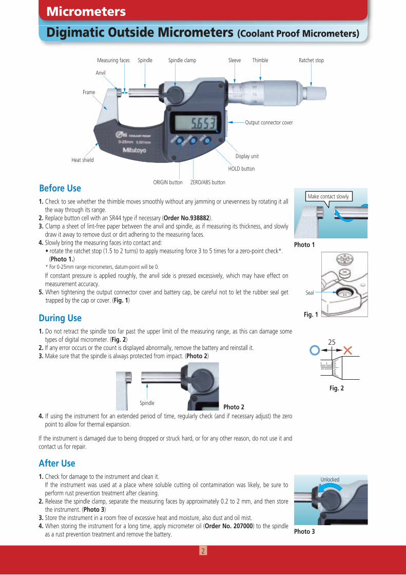
Measuring faces Spindle Spindle clamp Sleeve Thimble Ratchet stop
1. Check to see whether the thimble moves smoothly without any jamming or unevenness by rotating it all the way through its range.
2. Replace button cell with an SR44 type if necessary (Order No.938882).3. Clamp a sheet of lint-free paper between the anvil and spindle, as if measuring its thickness, and slowly
draw it away to remove dust or dirt adhering to the measuring faces.4. Slowly bring the measuring faces into contact and: • rotate the ratchet stop (1.5 to 2 turns) to apply measuring force 3 to 5 times for a zero-point check*. (Photo 1.)
* For 0-25mm range micrometers, datum-point will be 0.
If constant pressure is applied roughly, the anvil side is pressed excessively, which may have effect on measurement accuracy.
5. When tightening the output connector cover and battery cap, be careful not to let the rubber seal get trapped by the cap or cover. (Fig. 1)
1. Check for damage to the instrument and clean it. If the instrument was used at a place where soluble cutting oil contamination was likely, be sure to
perform rust prevention treatment after cleaning.2. Release the spindle clamp, separate the measuring faces by approximately 0.2 to 2 mm, and then store
the instrument. (Photo 3)3. Store the instrument in a room free of excessive heat and moisture, also dust and oil mist.4. When storing the instrument for a long time, apply micrometer oil (Order No. 207000) to the spindle
as a rust prevention treatment and remove the battery.
1. Do not retract the spindle too far past the upper limit of the measuring range, as this can damage some types of digital micrometer. (Fig. 2)
2. If any error occurs or the count is displayed abnormally, remove the battery and reinstall it.3. Make sure that the spindle is always protected from impact. (Photo 2)
4. If using the instrument for an extended period of time, regularly check (and if necessary adjust) the zero point to allow for thermal expansion.
If the instrument is damaged due to being dropped or struck hard, or for any other reason, do not use it and contact us for repair.
Photo 1
Photo 3
Fig. 1
Fig. 2
Make contact slowly.
Seal
Unlocked
SpindlePhoto 2
25
25
25
2
Outside Micrometers
Micrometers
Before Use
After Use
During Use
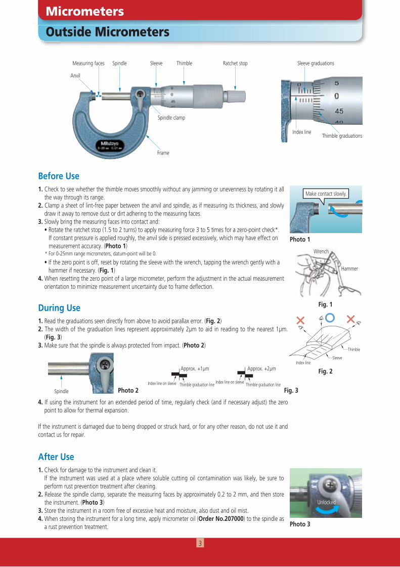
1. Check to see whether the thimble moves smoothly without any jamming or unevenness by rotating it all the way through its range.
2. Clamp a sheet of lint-free paper between the anvil and spindle, as if measuring its thickness, and slowly draw it away to remove dust or dirt adhering to the measuring faces.
3. Slowly bring the measuring faces into contact and: • Rotate the ratchet stop (1.5 to 2 turns) to apply measuring force 3 to 5 times for a zero-point check*. If constant pressure is applied roughly, the anvil side is pressed excessively, which may have effect on measurement accuracy. (Photo 1)
* For 0-25mm range micrometers, datum-point will be 0.
• If the zero point is off, reset by rotating the sleeve with the wrench, tapping the wrench gently with a hammer if necessary. (Fig. 1)4. When resetting the zero point of a large micrometer, perform the adjustment in the actual measurement
orientation to minimize measurement uncertainty due to frame deflection.
1. Check for damage to the instrument and clean it. If the instrument was used at a place where soluble cutting oil contamination was likely, be sure to
perform rust prevention treatment after cleaning.2. Release the spindle clamp, separate the measuring faces by approximately 0.2 to 2 mm, and then store
the instrument. (Photo 3)3. Store the instrument in a room free of excessive heat and moisture, also dust and oil mist.4. When storing the instrument for a long time, apply micrometer oil (Order No.207000) to the spindle as
a rust prevention treatment.
1. Read the graduations seen directly from above to avoid parallax error. (Fig. 2)2. The width of the graduation lines represent approximately 2µm to aid in reading to the nearest 1µm.
(Fig. 3)3. Make sure that the spindle is always protected from impact. (Photo 2)
4. If using the instrument for an extended period of time, regularly check (and if necessary adjust) the zero point to allow for thermal expansion.
If the instrument is damaged due to being dropped or struck hard, or for any other reason, do not use it and contact us for repair.
Photo 3
Fig. 1
Anvil
Measuring faces Spindle Sleeve graduationsSleeve Thimble Ratchet stop
Index line
Frame
Spindle clamp
Thimble graduations
Wrench
Hammer
Fig. 2
SleeveIndex line
Thimble
Photo 1
Make contact slowly.
Unlocked
Spindle Photo 2 Fig. 3Thimble graduation line Thimble graduation lineIndex line on sleeve Index line on sleeve
Approx. +2µmApprox. +1µm
3
Before Use
After Use
During Use
1. Check to see whether the thimble moves smoothly without any jamming or unevenness by rotating it all the way through its range.
2. Replace button cell with an SR44 type if necessary (Order No. 938882).3. Clamp a sheet of lint-free paper between the anvil and spindle, as if measuring its thickness, and
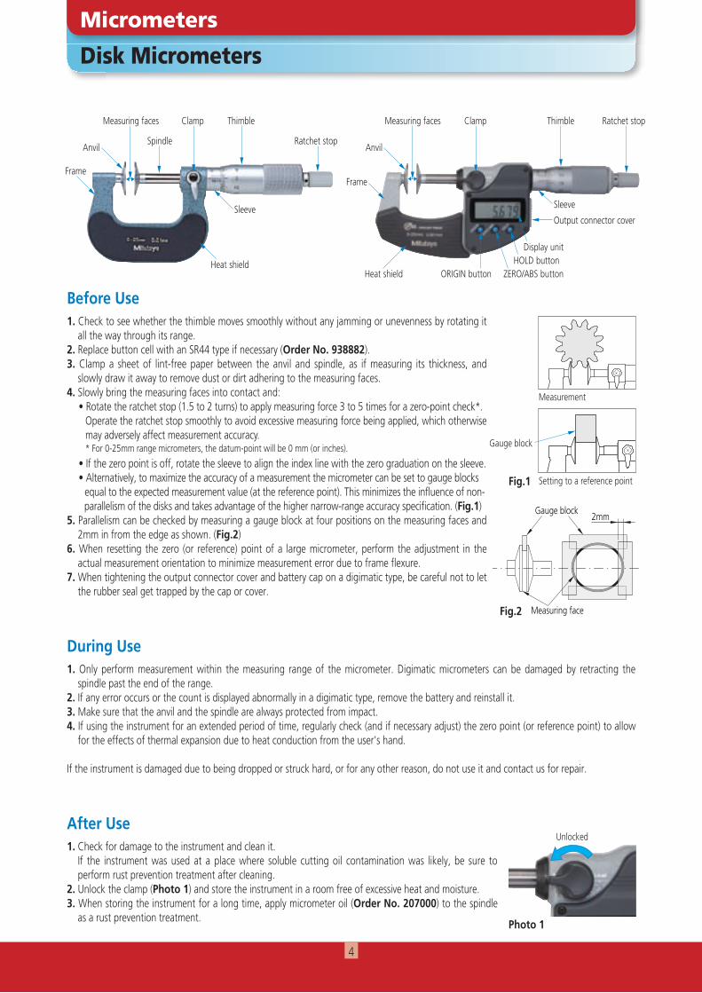
slowly draw it away to remove dust or dirt adhering to the measuring faces.4. Slowly bring the measuring faces into contact and: • Rotate the ratchet stop (1.5 to 2 turns) to apply measuring force 3 to 5 times for a zero-point check*. Operate the ratchet stop smoothly to avoid excessive measuring force being applied, which otherwise
may adversely affect measurement accuracy. * For 0-25mm range micrometers, the datum-point will be 0 mm (or inches).
• If the zero point is off, rotate the sleeve to align the index line with the zero graduation on the sleeve. • Alternatively, to maximize the accuracy of a measurement the micrometer can be set to gauge blocks equal to the expected measurement value (at the reference point). This minimizes the influence of non- parallelism of the disks and takes advantage of the higher narrow-range accuracy specification. (Fig.1) 5. Parallelism can be checked by measuring a gauge block at four positions on the measuring faces and
2mm in from the edge as shown. (Fig.2)6. When resetting the zero (or reference) point of a large micrometer, perform the adjustment in the
actual measurement orientation to minimize measurement error due to frame flexure.7. When tightening the output connector cover and battery cap on a digimatic type, be careful not to let
the rubber seal get trapped by the cap or cover.
1. Check for damage to the instrument and clean it. If the instrument was used at a place where soluble cutting oil contamination was likely, be sure to
perform rust prevention treatment after cleaning.2. Unlock the clamp (Photo 1) and store the instrument in a room free of excessive heat and moisture.3. When storing the instrument for a long time, apply micrometer oil (Order No. 207000) to the spindle
as a rust prevention treatment.
1. Only perform measurement within the measuring range of the micrometer. Digimatic micrometers can be damaged by retracting the spindle past the end of the range.
2. If any error occurs or the count is displayed abnormally in a digimatic type, remove the battery and reinstall it.3. Make sure that the anvil and the spindle are always protected from impact.4. If using the instrument for an extended period of time, regularly check (and if necessary adjust) the zero point (or reference point) to allow
for the effects of thermal expansion due to heat conduction from the user's hand.
If the instrument is damaged due to being dropped or struck hard, or for any other reason, do not use it and contact us for repair.
Anvil Anvil
Measuring faces Measuring facesClamp
Spindle Ratchet stop
Thimble
Sleeve Sleeve
Thimble Ratchet stop
ORIGIN button ZERO/ABS buttonHOLD button
Display unit
Heat shieldHeat shield
FrameFrame
Output connector cover
Clamp
2mmGauge block
Measuring faceFig.2
Fig.1
Photo 1
Disk Micrometers
Micrometers
Unlocked
Measurement
Gauge block
Setting to a reference point
4
Before Use
After Use
During Use
1. Check for damage to the instrument and clean it. If the instrument was used at a place where soluble cutting oil contamination was likely, be sure to perform rust prevention treatment after
cleaning.2. Unlock the clamp and store the instrument in a room free of excessive heat and moisture.3. When storing the instrument for a long time, apply micrometer oil (Order No. 207000) to the spindle as a rust prevention treatment and
remove the battery.
1. Only perform measurement within the measuring range of the micrometer. Digimatic micrometers can be damaged by retracting the spindle past the end of the range.
2. If any error occurs or the count is displayed abnormally on a digimatic type, remove the battery and reinstall it.3. Make sure that the spindle and contact points are always protected from impact.4. If using the instrument for an extended period of time, regularly check (and if necessary adjust) the zero point (or reference point) to allow
for the effects of thermal expansion due to heat conduction from the user's hand.
If the instrument is damaged due to being dropped or struck hard, or for any other reason, do not use it and contact us for repair.
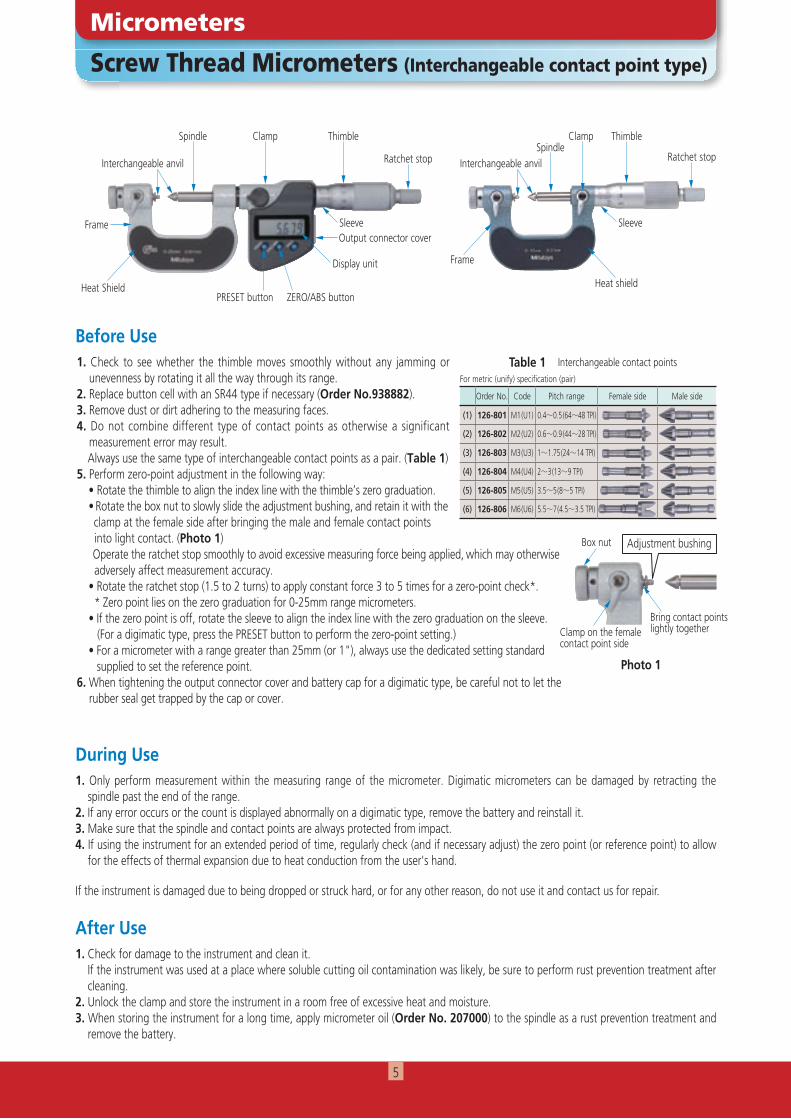
Interchangeable anvil Interchangeable anvil
SpindleSpindle
Clamp ClampThimble Thimble
Ratchet stop Ratchet stop
Frame
Heat Shield Heat shield
SleeveOutput connector cover
Display unit
PRESET button ZERO/ABS button
Frame
Sleeve
1. Check to see whether the thimble moves smoothly without any jamming or unevenness by rotating it all the way through its range.
2. Replace button cell with an SR44 type if necessary (Order No.938882).3. Remove dust or dirt adhering to the measuring faces. 4. Do not combine different type of contact points as otherwise a significant
measurement error may result. Always use the same type of interchangeable contact points as a pair. (Table 1)5. Perform zero-point adjustment in the following way: • Rotate the thimble to align the index line with the thimble’s zero graduation. • Rotate the box nut to slowly slide the adjustment bushing, and retain it with the clamp at the female side after bringing the male and female contact points into light contact. (Photo 1) Operate the ratchet stop smoothly to avoid excessive measuring force being applied, which may otherwise adversely affect measurement accuracy. • Rotate the ratchet stop (1.5 to 2 turns) to apply constant force 3 to 5 times for a zero-point check*. * Zero point lies on the zero graduation for 0-25mm range micrometers. • If the zero point is off, rotate the sleeve to align the index line with the zero graduation on the sleeve. (For a digimatic type, press the PRESET button to perform the zero-point setting.) • For a micrometer with a range greater than 25mm (or 1"), always use the dedicated setting standard supplied to set the reference point.6. When tightening the output connector cover and battery cap for a digimatic type, be careful not to let the
rubber seal get trapped by the cap or cover.
Box nut
Bring contact points lightly together
Adjustment bushing
Clamp on the female contact point side
Photo 1
Screw Thread Micrometers (Interchangeable contact point type)
Micrometers
Table 1For metric (unify) specification (pair)
Order No. Code Pitch range Female side Male side
(1) 126-801 M1 (U1) 0.4~0.5 (64~48 TPI)
(2) 126-802 M2 (U2) 0.6~0.9 (44~28 TPI)
(3) 126-803 M3 (U3) 1~1.75 (24~14 TPI)
(4) 126-804 M4 (U4) 2~3 (13~9 TPI)
(5) 126-805 M5 (U5) 3.5~5 (8~5 TPI)
(6) 126-806 M6 (U6) 5.5~7 (4.5~3.5 TPI)
Interchangeable contact points
5
Digimatic Holtest (Three-point Bore Micrometers)
Holtest
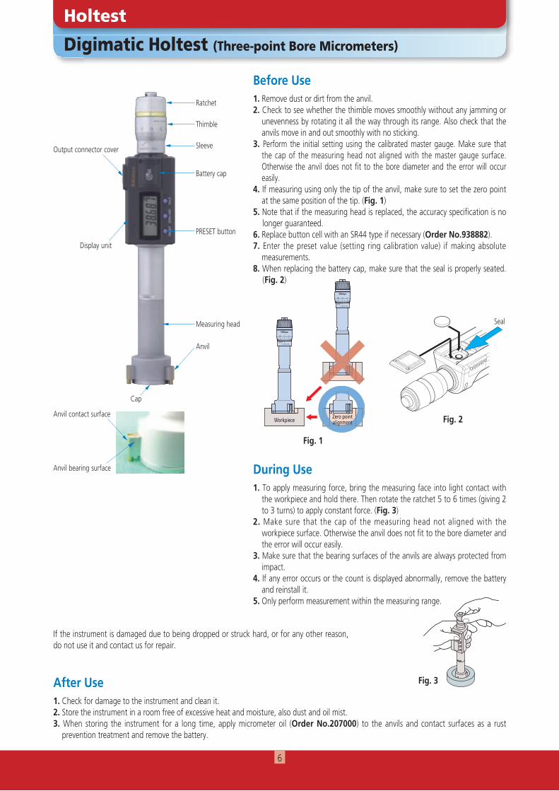
Ratchet
Thimble
Anvil
Sleeve
Battery cap
PRESET button
Measuring head
Output connector cover
Display unit
Before Use
During Use
1. Remove dust or dirt from the anvil.2. Check to see whether the thimble moves smoothly without any jamming or
unevenness by rotating it all the way through its range. Also check that the anvils move in and out smoothly with no sticking.
3. Perform the initial setting using the calibrated master gauge. Make sure that the cap of the measuring head not aligned with the master gauge surface. Otherwise the anvil does not fit to the bore diameter and the error will occur easily.
4. If measuring using only the tip of the anvil, make sure to set the zero point at the same position of the tip. (Fig. 1)
5. Note that if the measuring head is replaced, the accuracy specification is no longer guaranteed.
6. Replace button cell with an SR44 type if necessary (Order No.938882).7. Enter the preset value (setting ring calibration value) if making absolute
measurements.8. When replacing the battery cap, make sure that the seal is properly seated.
(Fig. 2)
1. To apply measuring force, bring the measuring face into light contact with the workpiece and hold there. Then rotate the ratchet 5 to 6 times (giving 2 to 3 turns) to apply constant force. (Fig. 3)
2. Make sure that the cap of the measuring head not aligned with the workpiece surface. Otherwise the anvil does not fit to the bore diameter and the error will occur easily.
3. Make sure that the bearing surfaces of the anvils are always protected from impact.
4. If any error occurs or the count is displayed abnormally, remove the battery and reinstall it.
5. Only perform measurement within the measuring range.
After Use1. Check for damage to the instrument and clean it.2. Store the instrument in a room free of excessive heat and moisture, also dust and oil mist.3. When storing the instrument for a long time, apply micrometer oil (Order No.207000) to the anvils and contact surfaces as a rust
prevention treatment and remove the battery.
Anvil bearing surface
Fig. 3
45 0 5
1DIV. 0.005mm45
測定物 基点合せ
45 0 5
1DIV. 0.005mm45
9401DIV. 0.005mm
5045
9401DIV. 0.005mm
5045
Zero pointalignmentWorkpiece
Seal
Fig. 1
Fig. 2Anvil contact surface
If the instrument is damaged due to being dropped or struck hard, or for any other reason, do not use it and contact us for repair.
Cap
6
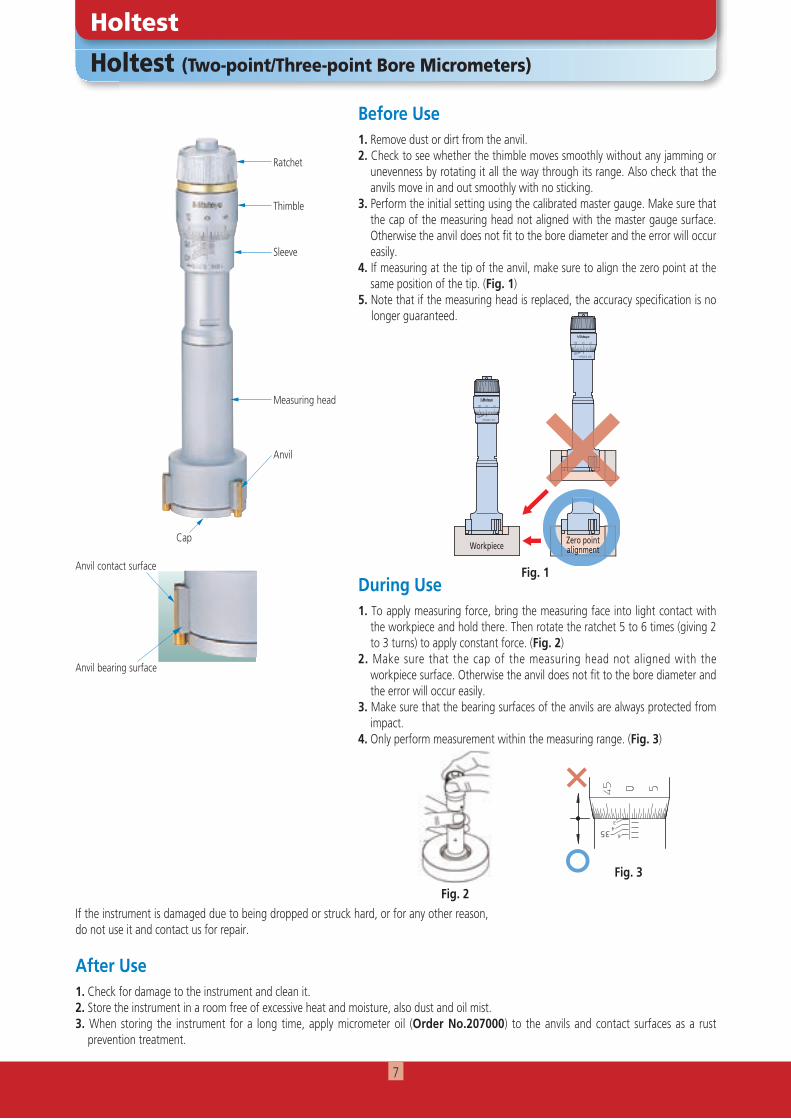
1. To apply measuring force, bring the measuring face into light contact with the workpiece and hold there. Then rotate the ratchet 5 to 6 times (giving 2 to 3 turns) to apply constant force. (Fig. 2)
2. Make sure that the cap of the measuring head not aligned with the workpiece surface. Otherwise the anvil does not fit to the bore diameter and the error will occur easily.
3. Make sure that the bearing surfaces of the anvils are always protected from impact.
4. Only perform measurement within the measuring range. (Fig. 3)
Holtest (Two-point/Three-point Bore Micrometers)
Holtest
Before Use1. Remove dust or dirt from the anvil.2. Check to see whether the thimble moves smoothly without any jamming or
unevenness by rotating it all the way through its range. Also check that the anvils move in and out smoothly with no sticking.
3. Perform the initial setting using the calibrated master gauge. Make sure that the cap of the measuring head not aligned with the master gauge surface. Otherwise the anvil does not fit to the bore diameter and the error will occur easily.
4. If measuring at the tip of the anvil, make sure to align the zero point at the same position of the tip. (Fig. 1)
5. Note that if the measuring head is replaced, the accuracy specification is no longer guaranteed.
After Use1. Check for damage to the instrument and clean it.2. Store the instrument in a room free of excessive heat and moisture, also dust and oil mist.3. When storing the instrument for a long time, apply micrometer oil (Order No.207000) to the anvils and contact surfaces as a rust
prevention treatment.
45 0 5
1DIV. 0.005mm45 4
測定物 基点合せ
45 0 5
1DIV. 0.005mm45 4
9401DIV. 0.005mm
5045
9401DIV. 0.005mm
5045
Zero pointalignmentWorkpiece
Fig. 1
Fig. 2
Ratchet
Thimble
Anvil
Sleeve
Measuring head
During Use
Anvil bearing surface
Anvil contact surface
If the instrument is damaged due to being dropped or struck hard, or for any other reason, do not use it and contact us for repair.
Cap
Fig. 3
356
43
2
7
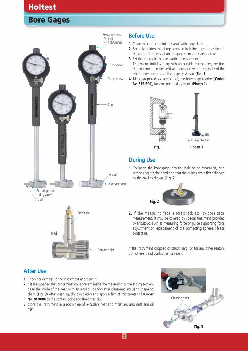
Bore Gages
Holtest
Protection cover(Option)(No.21DZA000)
Indicator
Guide
Clamp screw
Contact point
Exchange rod (fi xing screw)Anvil
Grip
Before Use
During Use
1. Clean the contact point and anvil with a dry cloth.2. Securely tighten the clamp screw to lock the gage in position. If
the gage still moves, clean the gage stem and clamp screw.3. Set the zero point before starting measurement. To perform initial setting with an outside micrometer, position
the micrometer in the vertical orientation with the spindle of the micrometer and anvil of the gage as shown. (Fig. 1)
4. Mitutoyo provides a useful tool, the bore gage checker (Order No.515-590), for zero-point adjustment. (Photo 1)
1. To insert the bore gage into the hole to be measured, or a setting ring, tilt the handle so that the guides enter first followed by the anvil as shown. (Fig. 2)
2. I f the measuring face is scratched, etc. by bore gage measurement, it may be covered by special treatment provided by Mitutoyo, such as measuring force or guide supporting force adjustment or replacement of the contacting sphere. Please contact us.
If the instrument dropped or struck hard, or for any other reason, do not use it and contact us for repair.
After Use1. Check for damage to the instrument and clean it.2. If it is suspected that contamination is present inside the measuring or the sliding section,
clean the inside of the head with an alcohol solution after disassembling using snap-ring pliers. (Fig. 3) After cleaning, dry completely and apply a film of micrometer oil (Order No.207000) to the contact point and the driver pin.
3. Store the instrument in a room free of excessive heat and moisture, also dust and oil mist.
Photo 1
Driver pin
Contact point
Head
Bore gage checker
Fig. 2
Fig. 1
Fig. 3
Cleaning parts
8
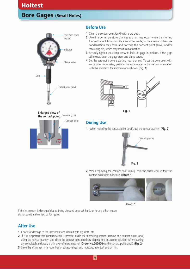
L
L / 2 L / 2
1. When replacing the contact point (anvil), use the special spanner. (Fig. 2)
2. When replacing the contact point (anvil), hold the screw end so that the contact point does not close. (Photo 1)
Bore Gages (Small Holes)
Holtest
Before Use
During Use
1. Clean the contact point (anvil) with a dry cloth.2. Avoid large temperature changes such as may occur when transferring
the instrument from outside a room to inside, or vice versa. Otherwise condensation may form and corrode the contact point (anvil) and/or measuring pin, which may result in malfunction.
3. Securely tighten the clamp screw to lock the gage in position. If the gage still moves, clean the gage stem and clamp screw.
4. Set the zero point before starting measurement. To set the zero point with an outside micrometer, position the micrometer in the vertical orientation with the spindle of the micrometer as shown. (Fig. 1)
After Use1. Check for damage to the instrument and clean it with dry cloth, etc.2. If it is suspected that contamination is present inside the measuring section, remove the contact point (anvil)
using the special spanner, and clean the contact point (anvil) by dipping into an alcohol solution. After cleaning, dry completely and apply a thin layer of micrometer oil (Order No.207000) to the contact point (anvil). (Fig. 2)
3. Store the instrument in a room free of excessive heat and moisture, also dust and oil mist.
Protection cover(option)
Indicator
Contact point (anvil)
Clamp screw
Grip
Enlarged view ofthe contact point Measuring pin
Contact point
Fig. 1
Photo 1
Fig. 2
Special spanner
If the instrument is damaged due to being dropped or struck hard, or for any other reason, do not use it and contact us for repair.
9

ABSOLUTE Digimatic Bore Gage CG-D
Holtest
Before Use
During Use
1. Clean the contact point and anvil with a dry cloth.2. When setting up the measuring
r ange u s ing space r s on the anvi l , always use the minimum number of spacers possible. (Fig. 1)
3. Replace button cell with an SR44 type if necessary (Order No.938882).
4. Make sure that the serial numbers of the display unit and the measuring unit are the same. If they are different then the accuracy specification cannot be guaranteed.
5. Make sure to engage the locating pin with the corresponding groove when connecting an extension rod (optional) (Figs. 2 and 3).
6. Make sure to perform the initial setting before starting measurement. To do this with an outside micrometer, keep the micrometer in the vertical orientation and position the anvil on the spindle as shown. (Fig. 4)
7. Mitutoyo provides a useful tool, the bore gage checker (Order No.515-590) for initial setting. (Photo 1)
1. To measure a hole or bore, insert the guided side first followed by the anvil side. (Photo 2)2. When measuring a hole or bore in the horizontal orientation, use with the anvil side downward.3. When reconnecting the extension rod (option) after removing it once, make sure to perform the initial
setting again.
If the instrument is damaged due to being dropped or struck hard, or for any other reason, do not use it and contact us for repair.
After Use1. Check for damage to the instrument and clean it.2. Store the instrument in a room free of excessive heat and moisture, also dust and oil mist.3. Do not clean the contact point by disassembling.
Guide
Contact point
Display unit
Clamp knob
Grip
Anvil
Fig. 1
Exchange anvil fi xing screwAnvilSpacers
Fig. 2 Fig. 3 Fig. 4
Photo 2
Photo 1
Locating groove
Locating pin
Measuring unit
Extension rod (option)
Anvil
Guide
Extension rod (option)
Display unit Measuring unit
Serial No.
PRESET button
Bore gage checker
10
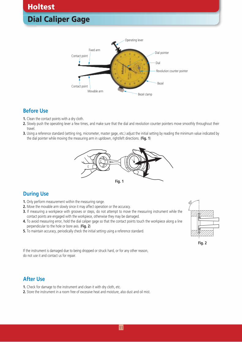
Dial Caliper Gage
Holtest
Before Use1. Clean the contact points with a dry cloth.2. Slowly push the operating lever a few times, and make sure that the dial and revolution counter pointers move smoothly throughout their
travel.3. Using a reference standard (setting ring, micrometer, master gage, etc.) adjust the initial setting by reading the minimum value indicated by
the dial pointer while moving the measuring arm in up/down, right/left directions. (Fig. 1)
During Use
After Use1. Check for damage to the instrument and clean it with dry cloth, etc.2. Store the instrument in a room free of excessive heat and moisture, also dust and oil mist.
1. Only perform measurement within the measuring range.2. Move the movable arm slowly since it may affect operation or the accuracy.3. If measuring a workpiece with grooves or steps, do not attempt to move the measuring instrument while the
contact points are engaged with the workpiece, otherwise they may be damaged. 4. To avoid measuring error, hold the dial caliper gage so that the contact points touch the workpiece along a line
perpendicular to the hole or bore axis. (Fig. 2)5. To maintain accuracy, periodically check the initial setting using a reference standard.
If the instrument is damaged due to being dropped or struck hard, or for any other reason, do not use it and contact us for repair.
Dial
Revolution counter pointer
Dial pointer
Operating lever
Bezel
Bezel clamp
Contact point
Fixed arm
Movable armContact point
90º
Fig. 2
Fig. 1
11
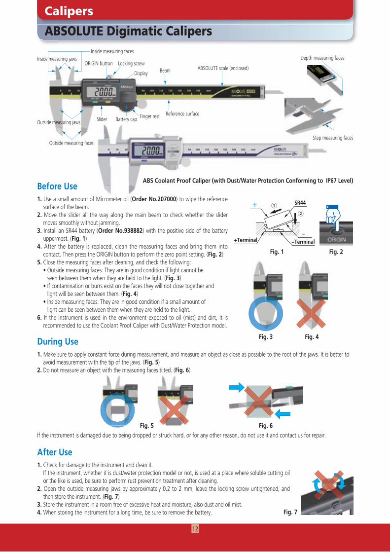
1. Make sure to apply constant force during measurement, and measure an object as close as possible to the root of the jaws. It is better to avoid measurement with the tip of the jaws. (Fig. 5)
2. Do not measure an object with the measuring faces tilted. (Fig. 6)
If the instrument is damaged due to being dropped or struck hard, or for any other reason, do not use it and contact us for repair.
ABSOLUTE Digimatic Calipers
Calipers
Locking screw
Display
Inside measuring facesInside measuring jaws
Outside measuring jaws
Outside measuring faces
Slider
Before Use
During Use
1. Use a small amount of Micrometer oil (Order No.207000) to wipe the reference surface of the beam.
2. Move the slider all the way along the main beam to check whether the slider moves smoothly without jamming.
3. Install an SR44 battery (Order No.938882) with the positive side of the battery uppermost. (Fig. 1)
4. After the battery is replaced, clean the measuring faces and bring them into contact. Then press the ORIGIN button to perform the zero point setting. (Fig. 2)
5. Close the measuring faces after cleaning, and check the following: • Outside measuring faces: They are in good condition if light cannot be seen between them when they are held to the light. (Fig. 3) • If contamination or burrs exist on the faces they will not close together and light will be seen between them. (Fig. 4) • Inside measuring faces: They are in good condition if a small amount of light can be seen between them when they are held to the light.6. If the instrument is used in the environment exposed to oil (mist) and dirt, it is
recommended to use the Coolant Proof Caliper with Dust/Water Protection model.
After Use
Battery capReference surface
Beam ABSOLUTE scale (enclosed)
Fig. 2
Fig. 5 Fig. 6
Fig. 7
ORIGIN button
Finger rest
SR44
−Terminal
②①
+Terminal−
+
Fig. 1
1. Check for damage to the instrument and clean it. If the instrument, whether it is dust/water protection model or not, is used at a place where soluble cutting oil
or the like is used, be sure to perform rust prevention treatment after cleaning.2. Open the outside measuring jaws by approximately 0.2 to 2 mm, leave the locking screw untightened, and
then store the instrument. (Fig. 7)3. Store the instrument in a room free of excessive heat and moisture, also dust and oil mist.4. When storing the instrument for a long time, be sure to remove the battery.
〇 〇 ××Fig. 3 Fig. 4
Depth measuring faces
ABS Coolant Proof Caliper (with Dust/Water Protection Conforming to IP67 Level)
Step measuring faces
12
〇〇×Fig. 2
Dial Calipers
Calipers
Before Use
During Use
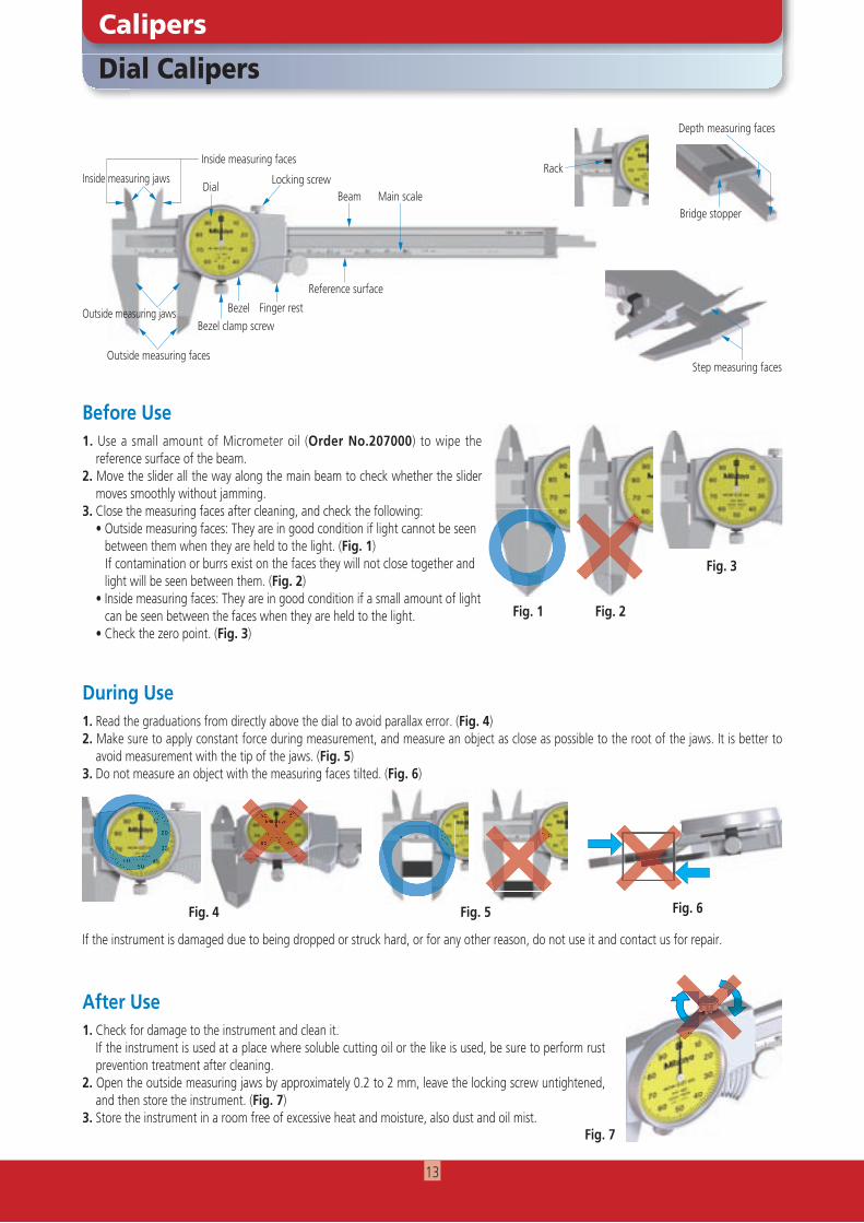
1. Use a small amount of Micrometer oil (Order No.207000) to wipe the reference surface of the beam.
2. Move the slider all the way along the main beam to check whether the slider moves smoothly without jamming.
3. Close the measuring faces after cleaning, and check the following: • Outside measuring faces: They are in good condition if light cannot be seen between them when they are held to the light. (Fig. 1) If contamination or burrs exist on the faces they will not close together and light will be seen between them. (Fig. 2) • Inside measuring faces: They are in good condition if a small amount of light can be seen between the faces when they are held to the light. • Check the zero point. (Fig. 3)
After Use1. Check for damage to the instrument and clean it. If the instrument is used at a place where soluble cutting oil or the like is used, be sure to perform rust
prevention treatment after cleaning.2. Open the outside measuring jaws by approximately 0.2 to 2 mm, leave the locking screw untightened,
and then store the instrument. (Fig. 7)3. Store the instrument in a room free of excessive heat and moisture, also dust and oil mist.
Fig. 3
Fig. 7
Fig. 1
1. Read the graduations from directly above the dial to avoid parallax error. (Fig. 4)2. Make sure to apply constant force during measurement, and measure an object as close as possible to the root of the jaws. It is better to
avoid measurement with the tip of the jaws. (Fig. 5)3. Do not measure an object with the measuring faces tilted. (Fig. 6)
If the instrument is damaged due to being dropped or struck hard, or for any other reason, do not use it and contact us for repair.
Step measuring faces
Depth measuring faces
Bridge stopper
Locking screw
Inside measuring faces
Inside measuring jaws
Outside measuring jaws
Outside measuring faces
Bezel clamp screwBezel
Reference surface
Beam Main scaleDial
Finger rest
Rack
〇×××〇〇 ×××××××××××
Fig. 4 Fig. 6Fig. 5
13
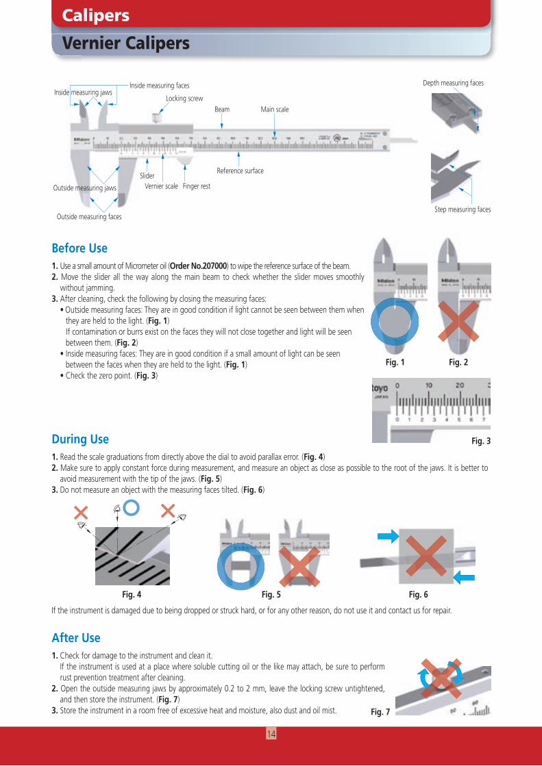
Vernier Calipers
Calipers
Locking screw
Inside measuring faces Depth measuring faces
Outside measuring jaws
Outside measuring faces
Slider
Before Use
During Use1. Read the scale graduations from directly above the dial to avoid parallax error. (Fig. 4)2. Make sure to apply constant force during measurement, and measure an object as close as possible to the root of the jaws. It is better to
avoid measurement with the tip of the jaws. (Fig. 5)3. Do not measure an object with the measuring faces tilted. (Fig. 6)
If the instrument is damaged due to being dropped or struck hard, or for any other reason, do not use it and contact us for repair.
After Use1. Check for damage to the instrument and clean it. If the instrument is used at a place where soluble cutting oil or the like may attach, be sure to perform
rust prevention treatment after cleaning.2. Open the outside measuring jaws by approximately 0.2 to 2 mm, leave the locking screw untightened,
and then store the instrument. (Fig. 7)3. Store the instrument in a room free of excessive heat and moisture, also dust and oil mist.
Vernier scale
Reference surface
Beam Main scale
Step measuring faces
Fig. 2
Fig. 3
Fig. 7
Fig. 4 Fig. 5 Fig. 6
Finger rest
Fig. 1
Inside measuring jaws
1. Use a small amount of Micrometer oil (Order No.207000) to wipe the reference surface of the beam.2. Move the slider all the way along the main beam to check whether the slider moves smoothly
without jamming.3. After cleaning, check the following by closing the measuring faces: • Outside measuring faces: They are in good condition if light cannot be seen between them when they are held to the light. (Fig. 1) If contamination or burrs exist on the faces they will not close together and light will be seen between them. (Fig. 2) • Inside measuring faces: They are in good condition if a small amount of light can be seen between the faces when they are held to the light. (Fig. 1) • Check the zero point. (Fig. 3)
14
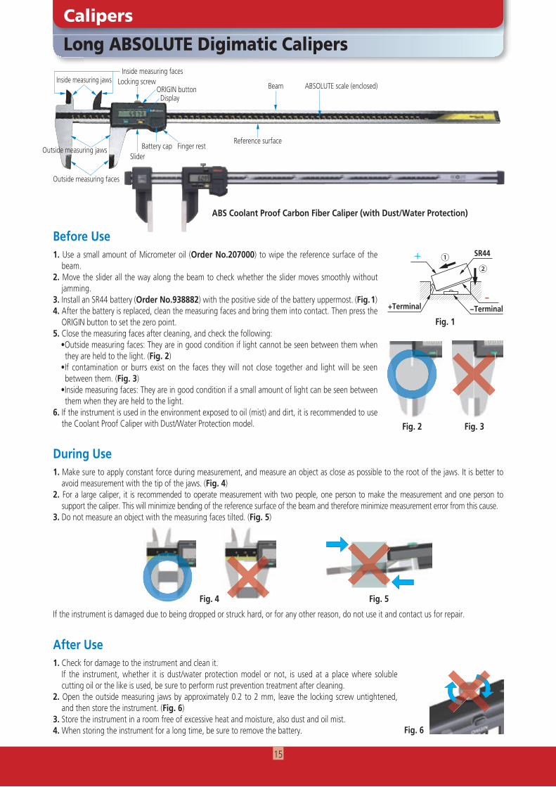
Long ABSOLUTE Digimatic Calipers
Calipers
1. Make sure to apply constant force during measurement, and measure an object as close as possible to the root of the jaws. It is better to avoid measurement with the tip of the jaws. (Fig. 4)
2. For a large caliper, it is recommended to operate measurement with two people, one person to make the measurement and one person to support the caliper. This will minimize bending of the reference surface of the beam and therefore minimize measurement error from this cause.
3. Do not measure an object with the measuring faces tilted. (Fig. 5)
Before Use
During Use
1. Use a small amount of Micrometer oil (Order No.207000) to wipe the reference surface of the beam.
2. Move the slider all the way along the beam to check whether the slider moves smoothly without jamming.
3. Install an SR44 battery (Order No.938882) with the positive side of the battery uppermost. (Fig. 1)4. After the battery is replaced, clean the measuring faces and bring them into contact. Then press the
ORIGIN button to set the zero point.5. Close the measuring faces after cleaning, and check the following:
•Outside measuring faces: They are in good condition if light cannot be seen between them when they are held to the light. (Fig. 2)
•If contamination or burrs exist on the faces they will not close together and light will be seen between them. (Fig. 3)
•Inside measuring faces: They are in good condition if a small amount of light can be seen between them when they are held to the light.
6. If the instrument is used in the environment exposed to oil (mist) and dirt, it is recommended to use the Coolant Proof Caliper with Dust/Water Protection model.
After Use1. Check for damage to the instrument and clean it. If the instrument, whether it is dust/water protection model or not, is used at a place where soluble
cutting oil or the like is used, be sure to perform rust prevention treatment after cleaning.2. Open the outside measuring jaws by approximately 0.2 to 2 mm, leave the locking screw untightened,
and then store the instrument. (Fig. 6)3. Store the instrument in a room free of excessive heat and moisture, also dust and oil mist.4. When storing the instrument for a long time, be sure to remove the battery.
Locking screw
Battery capReference surface
Beam ABSOLUTE scale (enclosed)ORIGIN button
SliderFinger rest
Inside measuring faces
Outside measuring faces
Inside measuring jaws
Outside measuring jaws
Display
〇×Fig. 2 Fig. 3
If the instrument is damaged due to being dropped or struck hard, or for any other reason, do not use it and contact us for repair.
SR44
−Terminal
②①
+Terminal−
+
Fig. 1
ABS Coolant Proof Carbon Fiber Caliper (with Dust/Water Protection)
Fig. 6
Fig. 4 Fig. 5
15
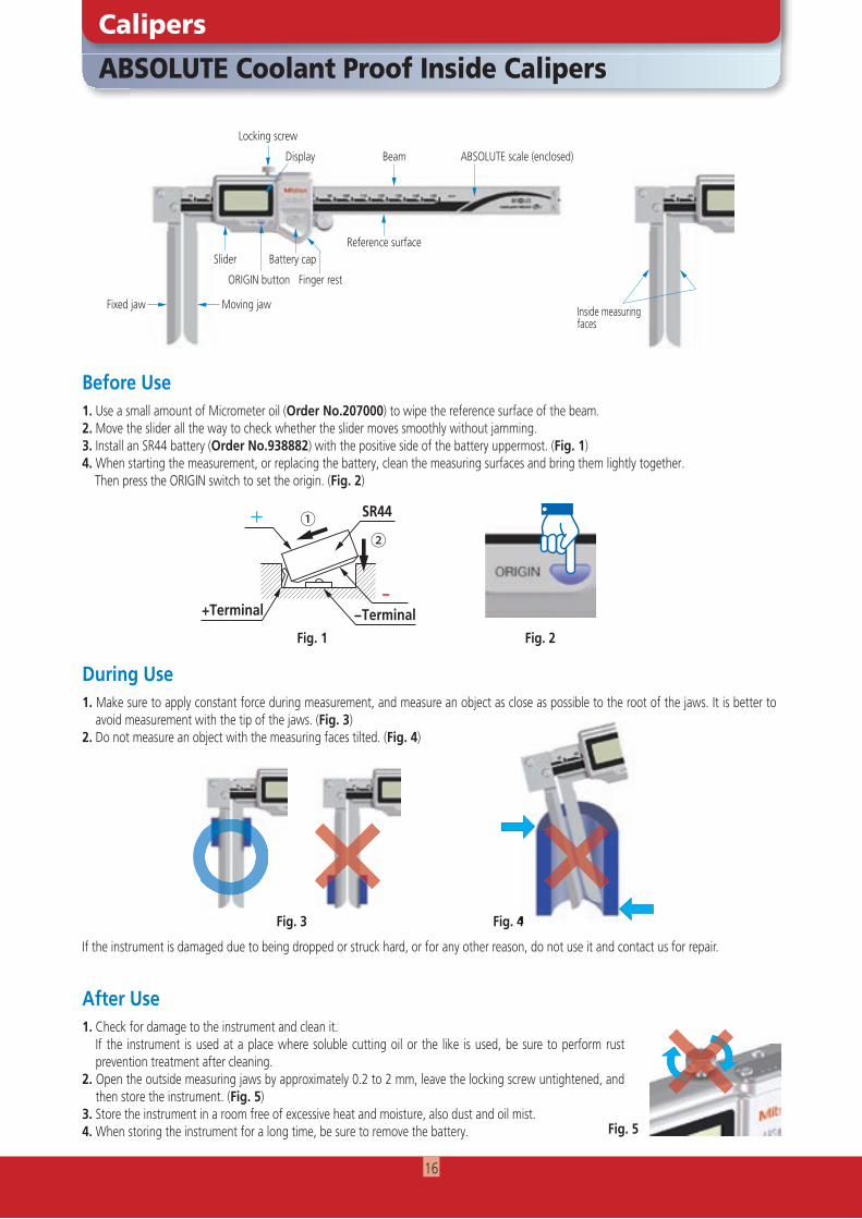
ABSOLUTE Coolant Proof Inside Calipers
Calipers
1. Make sure to apply constant force during measurement, and measure an object as close as possible to the root of the jaws. It is better to avoid measurement with the tip of the jaws. (Fig. 3)
2. Do not measure an object with the measuring faces tilted. (Fig. 4)
If the instrument is damaged due to being dropped or struck hard, or for any other reason, do not use it and contact us for repair.
Before Use
During Use
After Use1. Check for damage to the instrument and clean it. If the instrument is used at a place where soluble cutting oil or the like is used, be sure to perform rust
prevention treatment after cleaning.2. Open the outside measuring jaws by approximately 0.2 to 2 mm, leave the locking screw untightened, and
then store the instrument. (Fig. 5)3. Store the instrument in a room free of excessive heat and moisture, also dust and oil mist.4. When storing the instrument for a long time, be sure to remove the battery.
Locking screw
Fixed jaw
Slider
Moving jaw
Battery capReference surface
Beam ABSOLUTE scale (enclosed)
Inside measuringfaces
Fig. 5
Display
Finger rest
Fig. 4Fig. 4
ORIGIN button
SR44
−Terminal
②①
+Terminal−
+
Fig. 1
Fig. 3
1. Use a small amount of Micrometer oil (Order No.207000) to wipe the reference surface of the beam.2. Move the slider all the way to check whether the slider moves smoothly without jamming.3. Install an SR44 battery (Order No.938882) with the positive side of the battery uppermost. (Fig. 1)4. When starting the measurement, or replacing the battery, clean the measuring surfaces and bring them lightly together. Then press the ORIGIN switch to set the origin. (Fig. 2)
Fig. 2
16
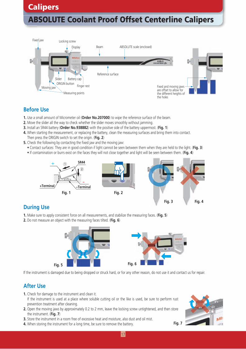
ABSOLUTE Coolant Proof Offset Centerline Calipers
Calipers
Locking screwFixed jaw
Moving jaw
Slider
Before Use
During Use
1. Use a small amount of Micrometer oil (Order No.207000) to wipe the reference surface of the beam.2. Move the slider all the way to check whether the slider moves smoothly without jamming.3. Install an SR44 battery (Order No.938882) with the positive side of the battery uppermost. (Fig. 1)4. When starting the measurement, or replacing the battery, clean the measuring surfaces and bring them into contact. Then press the ORIGIN switch to set the origin. (Fig. 2)5. Check the following by contacting the fixed jaw and the moving jaw: • Contact surfaces: They are in good condition if light cannot be seen between them when they are held to the light. (Fig. 3) • If contamination or burrs exist on the faces they will not close together and light will be seen between them. (Fig. 4)
1. Make sure to apply consistent force on all measurements, and stabilize the measuring faces. (Fig. 5)2. Do not measure an object with the measuring faces tilted. (Fig. 6)
If the instrument is damaged due to being dropped or struck hard, or for any other reason, do not use it and contact us for repair.
After Use1. Check for damage to the instrument and clean it. If the instrument is used at a place where soluble cutting oil or the like is used, be sure to perform rust
prevention treatment after cleaning.2. Open the moving jaws by approximately 0.2 to 2 mm, leave the locking screw untightened, and then store
the instrument. (Fig. 7)3. Store the instrument in a room free of excessive heat and moisture, also dust and oil mist.4. When storing the instrument for a long time, be sure to remove the battery.
Reference surface
Beam ABSOLUTE scale (enclosed)
Fixed and moving jaws are offset to allow for the different heights of the holes
Fig. 4Fig. 3
Display
Fig. 2
Fig. 5 Fig. 6
Battery cap
Fig. 7
Finger restORIGIN button
SR44
−Terminal
②①
+Terminal−
+
Fig. 1
Measuring points
17
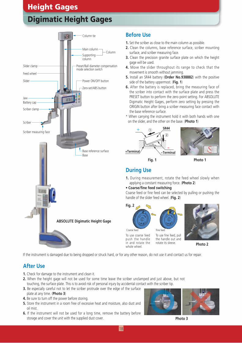
Digimatic Height Gages
Height Gages
1. During measurement, rotate the feed wheel slowly when applying a constant measuring force. (Photo 2)
• Coarse/fine feed switchingCoarse feed or fine feed can be selected by pulling or pushing the handle of the slider feed wheel. (Fig. 2)
Before Use
During Use
1. Set the scriber as close to the main column as possible.2. Clean the columns, base reference surface, scriber mounting
surface, and scriber measuring face.3. Clean the precision granite surface plate on which the height
gage will be used.4. Move the slider throughout its range to check that the
movement is smooth without jamming.5. Install an SR44 battery (Order No.938882) with the positive
side of the battery uppermost. (Fig. 1)6. After the battery is replaced, bring the measuring face of
the scriber into contact with the surface plate and press the PRESET button to perform the zero point setting. For ABSOLUTE Digimatic Height Gages, perform zero setting by pressing the ORIGIN button after bring a scriber measuring face contact with the base reference surface.
* When carrying the instrument hold it with both hands with one on the slider, and the other on the base. (Photo 1)
After Use1. Check for damage to the instrument and clean it.2. When the height gage will not be used for some time leave the scriber unclamped and just above, but not
touching, the surface plate. This is to avoid risk of personal injury by accidental contact with the scriber tip.3. Be especially careful not to let the scriber protrude over the edge of the surface
plate at any time. (Photo 3)4. Be sure to turn off the power before storing.5. Store the instrument in a room free of excessive heat and moisture, also dust and
oil mist.6. If the instrument will not be used for a long time, remove the battery before
storage and cover the unit with the supplied dust cover.
Photo 1Fig. 1
Fig. 2
To use coarse feed push the hand le in and rotate the whole wheel.
To use fine feed, pull the handle out and rotate its sleeve.
Fine feedCoarse feed
Photo 3
Column tie
Power ON/OFF button
Zero-set/ABS button
Preset/Ball diameter compensation mode selection switch
Base reference surfaceBase
Feed wheel
Slider clamp
Slider
Battery cap
Scriber clamp
Scriber
Scriber measuring face
Jaw
Main column
Supportingcolumn
Column
SR44
−Terminal
②①
+Terminal−
+
Photo 2
If the instrument is damaged due to being dropped or struck hard, or for any other reason, do not use it and contact us for repair.
ABSOLUTE Digimatic Height Gage
18
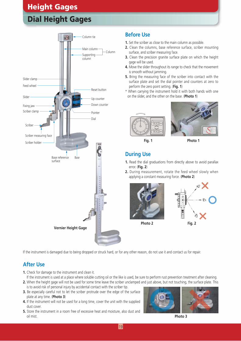
Dial Height Gages
Height Gages
1. Read the dial graduations from directly above to avoid parallax error. (Fig. 2)
2. During measurement, rotate the feed wheel slowly when applying a constant measuring force. (Photo 2)
Before Use
During Use
1. Set the scriber as close to the main column as possible.2. Clean the columns, base reference surface, scriber mounting
surface, and scriber measuring face.3. Clean the precision granite surface plate on which the height
gage will be used.4. Move the slider throughout its range to check that the movement
is smooth without jamming.5. Bring the measuring face of the scriber into contact with the
surface plate and set the dial pointer and counters at zero to perform the zero point setting. (Fig. 1)
* When carrying the instrument hold it with both hands with one on the slider, and the other on the base. (Photo 1)
After Use1. Check for damage to the instrument and clean it. If the instrument is used at a place where soluble cutting oil or the like is used, be sure to perform rust prevention treatment after cleaning.2. When the height gage will not be used for some time leave the scriber unclamped and just above, but not touching, the surface plate. This
is to avoid risk of personal injury by accidental contact with the scriber tip.3. Be especially careful not to let the scriber protrude over the edge of the surface
plate at any time. (Photo 3)4. If the instrument will not be used for a long time, cover the unit with the supplied
dust cover.5. Store the instrument in a room free of excessive heat and moisture, also dust and
oil mist. Photo 3
Photo 1Fig. 1
Reset button
Up counter
Down counter
Pointer
Dial
Slider clamp
Feed wheel
Slider
Fixing jaw
Scriber clamp
Scriber holder
Scriber
Scriber measuring face
Base
Fig. 2
Base referencesurface
Photo 2
00
1010
20
30
4050
60
70
80
90
20
30
4050
60
70
80
90
0 0 0 mm
mm0 0 0
If the instrument is damaged due to being dropped or struck hard, or for any other reason, do not use it and contact us for repair.
Vernier Height Gage
Column tie
Main column
Supportingcolumn
Column
19
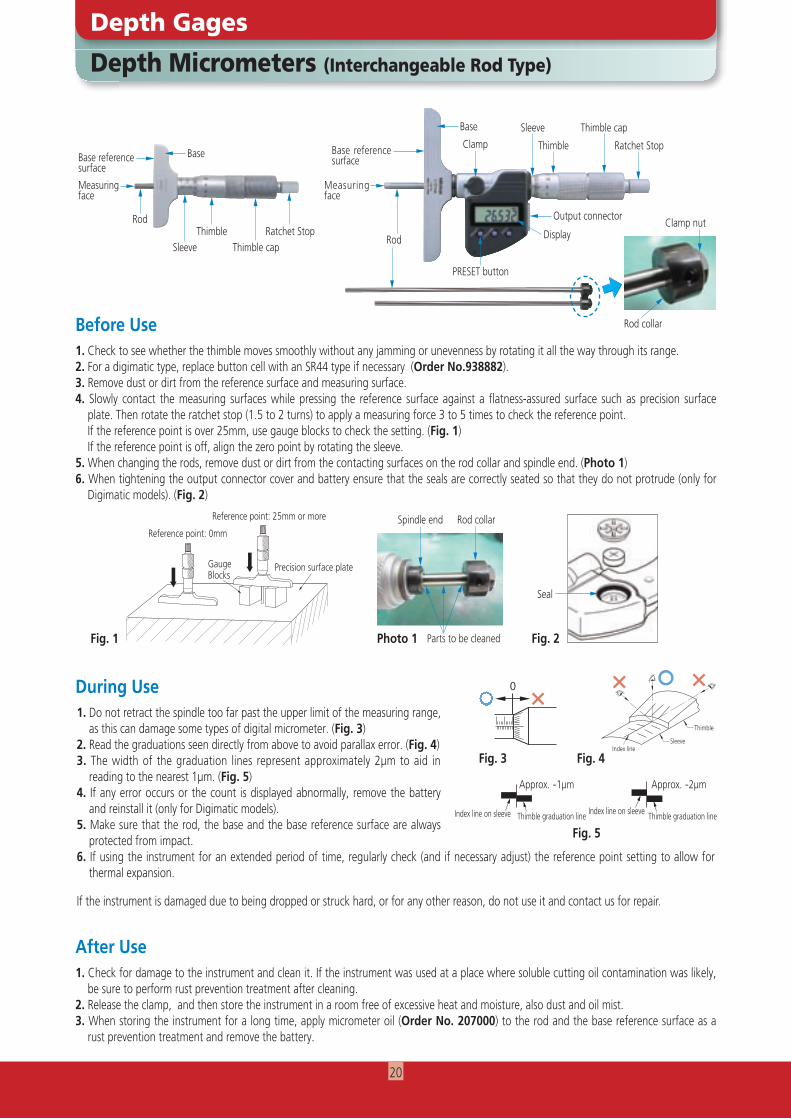
Measuring face
Depth Micrometers (Interchangeable Rod Type)
Depth Gages
Before Use
During Use
After Use1. Check for damage to the instrument and clean it. If the instrument was used at a place where soluble cutting oil contamination was likely,
be sure to perform rust prevention treatment after cleaning.2. Release the clamp, and then store the instrument in a room free of excessive heat and moisture, also dust and oil mist.3. When storing the instrument for a long time, apply micrometer oil (Order No. 207000) to the rod and the base reference surface as a
rust prevention treatment and remove the battery.
1. Check to see whether the thimble moves smoothly without any jamming or unevenness by rotating it all the way through its range.2. For a digimatic type, replace button cell with an SR44 type if necessary (Order No.938882).3. Remove dust or dirt from the reference surface and measuring surface.4. Slowly contact the measuring surfaces while pressing the reference surface against a flatness-assured surface such as precision surface
plate. Then rotate the ratchet stop (1.5 to 2 turns) to apply a measuring force 3 to 5 times to check the reference point. If the reference point is over 25mm, use gauge blocks to check the setting. (Fig. 1) If the reference point is off, align the zero point by rotating the sleeve.5. When changing the rods, remove dust or dirt from the contacting surfaces on the rod collar and spindle end. (Photo 1)6. When tightening the output connector cover and battery ensure that the seals are correctly seated so that they do not protrude (only for
Digimatic models). (Fig. 2)
1. Do not retract the spindle too far past the upper limit of the measuring range, as this can damage some types of digital micrometer. (Fig. 3)
2. Read the graduations seen directly from above to avoid parallax error. (Fig. 4)3. The width of the graduation lines represent approximately 2µm to aid in
reading to the nearest 1µm. (Fig. 5)4. If any error occurs or the count is displayed abnormally, remove the battery
and reinstall it (only for Digimatic models).5. Make sure that the rod, the base and the base reference surface are always
protected from impact. 6. If using the instrument for an extended period of time, regularly check (and if necessary adjust) the reference point setting to allow for
thermal expansion.
If the instrument is damaged due to being dropped or struck hard, or for any other reason, do not use it and contact us for repair.
Base
Base reference surface
ClampSleeve Thimble cap
Thimble Ratchet Stop
Rod
PRESET button
Display
Output connectorClamp nut
Rod collar
Gauge Blocks
Precision surface plate
Reference point: 0mm
Reference point: 25mm or more
Photo 1
Spindle end Rod collar
Parts to be cleaned
Measuring face
BaseBase reference surface
Rod
Sleeve Thimble capThimble Ratchet Stop
Fig. 1
0
0
0
Fig. 5Thimble graduation line Thimble graduation lineIndex line on sleeve Index line on sleeve
Approx. -2µmApprox. -1µm
SleeveIndex line
Thimble
Fig. 3 Fig. 4
Fig. 2
Seal
20
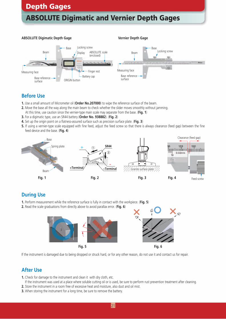
ABSOLUTE Digimatic and Vernier Depth Gages
Depth Gages
1. Perform measurement while the reference surface is fully in contact with the workpiece. (Fig. 5)2. Read the scale graduations from directly above to avoid parallax error. (Fig. 6)
If the instrument is damaged due to being dropped or struck hard, or for any other reason, do not use it and contact us for repair.
Before Use
During Use
1. Use a small amount of Micrometer oil (Order No.207000) to wipe the reference surface of the beam.2. Move the base all the way along the main beam to check whether the slider moves smoothly without jamming. At this time, use caution since the vernier-type main scale may separate from the base. (Fig. 1)3. For a digimatic type, use an SR44 battery (Order No. 938882). (Fig. 2)4. Set up the origin point on a flatness-assured surface such as precision surface plate. (Fig. 3)5. If using a vernier-type scale equipped with fine feed, adjust the feed screw so that there is always clearance (feed gap) between the fine
feed device and the base. (Fig. 4)
After Use1. Check for damage to the instrument and clean it with dry cloth, etc. If the instrument was used at a place where soluble cutting oil or is used, be sure to perform rust prevention treatment after cleaning.2. Store the instrument in a room free of excessive heat and moisture, also dust and oil mist.3. When storing the instrument for a long time, be sure to remove the battery.
Base BaseDisplay
Battery capORIGIN button
Measuring face Measuring face
Beam BeamABSOLUTE scale (enclosed)
Base reference surface
Base reference surface
Finger rest
Locking screw
ABSOLUTE Digimatic Depth Gage Vernier Depth Gage
Fig. 2
Base
Beam Granite surface plate
Fig. 3
Clearance (feed gap)
Fig. 1 Feed screwFig. 4
Fig. 5
〇 ××
Spring plate
Locking screw
SR44
−Terminal
②①
+Terminal−
+
Fig. 6
21
SR44
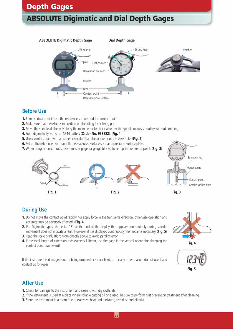
ABSOLUTE Digimatic and Dial Depth Gages
Depth Gages
1. Do not move the contact point rapidly nor apply force in the transverse direction, otherwise operation and accuracy may be adversely affected. (Fig. 4)
2. For Digimatic types, the letter "E" at the end of the display that appears momentarily during spindle movement does not indicate a fault. However, if it is displayed continuously then repair is necessary. (Fig. 5)
3. Read the scale graduations from directly above to avoid parallax error. 4. If the total length of extension rods exceeds 110mm, use the gage in the vertical orientation (keeping the
contact point downward).
If the instrument is damaged due to being dropped or struck hard, or for any other reason, do not use it and contact us for repair.
Before Use
During Use
1. Remove dust or dirt from the reference surface and the contact point.2. Make sure that a washer is in position on the lifting lever fixing part.3. Move the spindle all the way along the main beam to check whether the spindle moves smoothly without jamming.4. For a digimatic type, use an SR44 battery (Order No. 938882). (Fig. 1)5. Use a contact point with a diameter smaller than the diameter of the base hole. (Fig. 2)6. Set up the reference point on a flatness-assured surface such as a precision surface plate.7. When using extension rods, use a master gage (or gauge blocks) to set up the reference point. (Fig. 3)
After Use1. Check for damage to the instrument and clean it with dry cloth, etc.2. If the instrument is used at a place where soluble cutting oil or is used, be sure to perform rust prevention treatment after cleaning. 3. Store the instrument in a room free of excessive heat and moisture, also dust and oil mist.
Fig. 3
Fig. 5
Holder
BaseContact pointBase reference surface
ABSOLUTE Digimatic Depth Gage Dial Depth Gage
Lifting lever Lifting lever
Display Dial pointer
Revolution counter
Washer
Fig. 2
Extension rod
Contact point
Granite surface plate
Master gauge
Fig. 4
Fig. 1
22
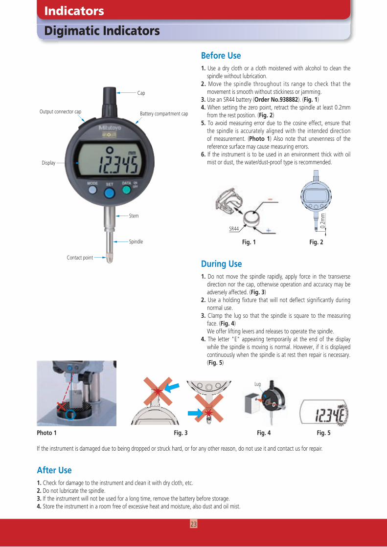
Digimatic Indicators
Indicators
Before Use1. Use a dry cloth or a cloth moistened with alcohol to clean the
spindle without lubrication.2. Move the spindle throughout its range to check that the
movement is smooth without stickiness or jamming.3. Use an SR44 battery (Order No.938882). (Fig. 1)4. When setting the zero point, retract the spindle at least 0.2mm
from the rest position. (Fig. 2)5. To avoid measuring error due to the cosine effect, ensure that
the spindle is accurately aligned with the intended direction of measurement. (Photo 1) Also note that unevenness of the reference surface may cause measuring errors.
6. If the instrument is to be used in an environment thick with oil mist or dust, the water/dust-proof type is recommended.
During Use
After Use1. Check for damage to the instrument and clean it with dry cloth, etc.2. Do not lubricate the spindle.3. If the instrument will not be used for a long time, remove the battery before storage.4. Store the instrument in a room free of excessive heat and moisture, also dust and oil mist.
Contact point
Display
Output connector cap
Cap
Battery compartment cap
Stem
Spindle
0.2m
m
Fig. 2
Photo 1
×〇 ×〇 ×
1. Do not move the spindle rapidly, apply force in the transverse direction nor the cap, otherwise operation and accuracy may be adversely affected. (Fig. 3)
2. Use a holding fixture that will not deflect significantly during normal use.
3. Clamp the lug so that the spindle is square to the measuring face. (Fig. 4)
We offer lifting levers and releases to operate the spindle.4. The letter "E" appearing temporarily at the end of the display
while the spindle is moving is normal. However, if it is displayed continuously when the spindle is at rest then repair is necessary. (Fig. 5)
Lug
Fig. 3 Fig. 4 Fig. 5
SR44
Fig. 1
If the instrument is damaged due to being dropped or struck hard, or for any other reason, do not use it and contact us for repair.
××××××××××××××××××××××××××××××××××××××××××××××××××××××××××××××××××××××××××××××××××××××××××××××××××××××××××××××××××××××××××××××××××××××××××××××××××××××××××××××××××××××××××××××××××××××××××××××××××××××××××××××××××××××××××××××××××××××××××××××××××××××××××××××××××××××××××××××××××××××××××××××××××××××××××××××××××××××××××××××××××××××××××××××××××××××××××××××××
23
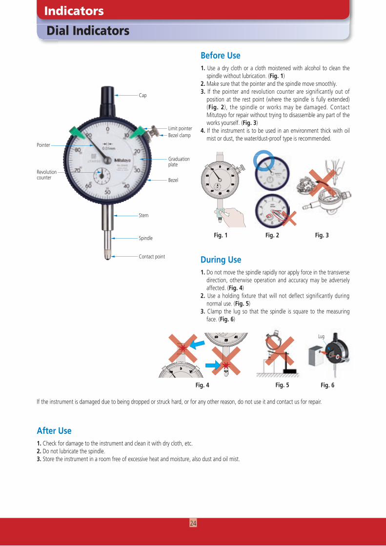
1. Use a dry cloth or a cloth moistened with alcohol to clean the spindle without lubrication. (Fig. 1)
2. Make sure that the pointer and the spindle move smoothly.3. If the pointer and revolution counter are significantly out of
position at the rest point (where the spindle is fully extended) (Fig. 2), the spindle or works may be damaged. Contact Mitutoyo for repair without trying to disassemble any part of the works yourself. (Fig. 3)
4. If the instrument is to be used in an environment thick with oil mist or dust, the water/dust-proof type is recommended.
4 5 678
9
32
1 0
Dial Indicators
Indicators
1. Do not move the spindle rapidly nor apply force in the transverse direction, otherwise operation and accuracy may be adversely affected. (Fig. 4)
2. Use a holding fixture that will not deflect significantly during normal use. (Fig. 5)
3. Clamp the lug so that the spindle is square to the measuring face. (Fig. 6)
Before Use
During Use
After Use1. Check for damage to the instrument and clean it with dry cloth, etc.2. Do not lubricate the spindle.3. Store the instrument in a room free of excessive heat and moisture, also dust and oil mist.
Fig. 3Fig. 2Fig. 1
Lug
Fig. 5
Limit pointerBezel clamp
Graduationplate
Bezel
Stem
Spindle
Contact point
Cap
Pointer
Revolution counter
If the instrument is damaged due to being dropped or struck hard, or for any other reason, do not use it and contact us for repair.
10
512.8
38.8
30° 30°
4 5 678
9
32
1 0
×××××××××××××××××××××××××××××××××××××××××××××××××××××××××××××××××××××××××××××××××××××××××××××××××××××××××××××××××××××××××××××××××××××××××××××××××××××××××××××××××××××××××××××××××××××××××××××××××××××××××××××××××××××××××××××××××××××××××××××××××××××××××××××××××××××××××××××××××××××××××××××××××××××××××××××××××××××××××××××××××××××××××××××××××××××××××××××××××××××××××××××××××××××××××××××××××××××××××××××××××××××××××××××××××××××××××××××××××××××
10
512.8
38.8
30° 30°
4 5 678
9
32
1 0
××××××××××××××××××××××××××××××××××××××××××××××××××××××××××××××××××××××××××××××××××××××××××××××××××××××××××××××××××××××××××××××××××××××××××××××××××××××××××××××××××××××××××××××××××××××××××××××××××××××××××××××××××××××××××××××××××××××××××××××××××××××××××××××××××××××××××××××××××××××××××××××××××××××××××××××××××××××××××××××××××××××××××××××××××××××××××××××××××××××××××××××××××××××××××××××××××××××××××××××××××××××××××××××××××××××××××××××××××××××××××××××××××××××××××××××××××××××××××××××××××××××××××××××××××××××××××××××××××××××××××××××××××××Fig. 4
Lug
Fig. 6
24
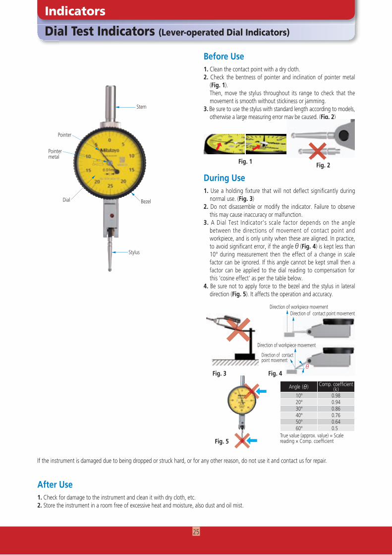
Dial Test Indicators (Lever-operated Dial Indicators)
Indicators
Before Use1. Clean the contact point with a dry cloth.2. Check the bentness of pointer and inclination of pointer metal
(Fig. 1). Then, move the stylus throughout its range to check that the
movement is smooth without stickiness or jamming. 3. Be sure to use the stylus with standard length according to models,
otherwise a large measuring error may be caused. (Fig. 2)
During Use
After Use1. Check for damage to the instrument and clean it with dry cloth, etc.2. Store the instrument in a room free of excessive heat and moisture, also dust and oil mist.
Bezel
1. Use a holding fixture that will not deflect significantly during normal use. (Fig. 3)
2. Do not disassemble or modify the indicator. Failure to observe this may cause inaccuracy or malfunction.
3. A Dial Test Indicator's scale factor depends on the angle between the directions of movement of contact point and workpiece, and is only unity when these are aligned. In practice, to avoid significant error, if the angle (Fig. 4) is kept less than 10° during measurement then the effect of a change in scale factor can be ignored. If this angle cannot be kept small then a factor can be applied to the dial reading to compensation for this 'cosine effect' as per the table below.
4. Be sure not to apply force to the bezel and the stylus in lateral direction (Fig. 5). It affects the operation and accuracy.
Pointer
Pointermetal
Dial
Stylus
Fig. 3 Fig. 4
Direction of workpiece movementDirection of contact point movement
Direction of workpiece movement
Direction of contact point movement
Angle ( ) Comp. coeffi cient(k)
10° 0.9820° 0.9430° 0.8640° 0.7650° 0.6460° 0.5
True value (approx. value) = Scalereading × Comp. coeffi cient
Stem
If the instrument is damaged due to being dropped or struck hard, or for any other reason, do not use it and contact us for repair.
Fig. 2Fig. 1
××
××
Fig. 5
25
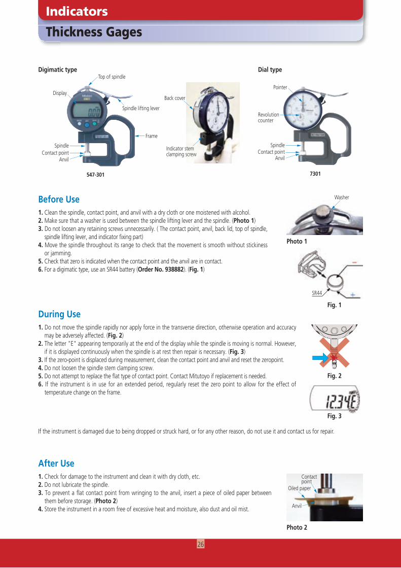
Thickness Gages
Indicators
1. Do not move the spindle rapidly nor apply force in the transverse direction, otherwise operation and accuracy may be adversely affected. (Fig. 2)
2. The letter "E" appearing temporarily at the end of the display while the spindle is moving is normal. However, if it is displayed continuously when the spindle is at rest then repair is necessary. (Fig. 3)
3. If the zero-point is displaced during measurement, clean the contact point and anvil and reset the zeropoint.4. Do not loosen the spindle stem clamping screw.5. Do not attempt to replace the flat type of contact point. Contact Mitutoyo if replacement is needed.6. If the instrument is in use for an extended period, regularly reset the zero point to allow for the effect of
temperature change on the frame.
Before Use
During Use
After Use1. Check for damage to the instrument and clean it with dry cloth, etc.2. Do not lubricate the spindle.3. To prevent a flat contact point from wringing to the anvil, insert a piece of oiled paper between
them before storage. (Photo 2)4. Store the instrument in a room free of excessive heat and moisture, also dust and oil mist.
Fig. 2
7301
Top of spindleDigimatic type Dial type
DisplayPointer
Spindle lifting lever
547-301
Frame
Spindle SpindleContact point Contact point
Anvil Anvil
Back cover
Indicator stem clamping screw
Revolution counter
Photo 1
Photo 2
Contactpoint
Oiled paper
Anvil
1. Clean the spindle, contact point, and anvil with a dry cloth or one moistened with alcohol.2. Make sure that a washer is used between the spindle lifting lever and the spindle. (Photo 1)3. Do not loosen any retaining screws unnecessarily. ( The contact point, anvil, back lid, top of spindle,
spindle lifting lever, and indicator fixing part)4. Move the spindle throughout its range to check that the movement is smooth without stickiness
or jamming.5. Check that zero is indicated when the contact point and the anvil are in contact.6. For a digimatic type, use an SR44 battery (Order No. 938882). (Fig. 1)
If the instrument is damaged due to being dropped or struck hard, or for any other reason, do not use it and contact us for repair.
SR44
Fig. 3
Fig. 1
Washer
××××××××××××××××××××××××××××××××××××××××××××××××××××××××××××××××××××××××
26
If the instrument is damaged due to being dropped or struck hard, or for any other reason, do not use it and contact us for repair.
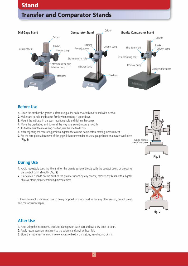
1. Clean the anvil or the granite surface using a dry cloth or a cloth moistened with alcohol.2. Make sure to hold the bracket firmly when moving it up or down.3. Mount the indicator in the stem mounting hole and tighten the clamp.4. Move the bracket up and down all the way to ensure it moves smoothly.5. To finely adjust the measuring position, use the fine feed knob.6. After adjusting the measuring position, tighten the column clamp before starting measurement.7. For the zero-point adjustment of the gage, it is recommended to use a gauge block or a master workpiece.
(Fig. 1)
Transfer and Comparator Stands
Stand
Before Use
During Use
After Use1. After using the instrument, check for damages on each part and use a dry cloth to clean.2. Apply rust prevention treatment to the column and anvil without fail.3. Store the instrument in a room free of excessive heat and moisture, also dust and oil mist.
Indicator clampStem mounting hole
Steel anvil
Dial Gage Stand Comparator Stand Granite Comparator Stand
Fine adjustment
Column
Bracket
Column clamp
Column
Column clampBracket
Stem mounting hole
Indicator clamp
Steel anvil
Column
BracketColumn clamp
Indicator clamp
Stem mounting hole
Fine adjustment
Granite surface plate
1. Avoid repeatedly touching the anvil or the granite surface directly with the contact point, or dropping the contact point abruptly. (Fig. 2)
2. If a scratch is made on the anvil or the granite surface by any chance, remove any burrs with a lightly abrasive stone before continuing measurement.
Fine adjustment
Fig. 1
×××××××××××××××××××××××××××××××××××××××××××××××××××××××××××××××××××××××××××××××××××××××××××××××××××××××××××××××××××××××××××××××××××××××××××××××××××××××××××××××××××××××××××××××××××××××××××××××××××××××××××××××××××××××××××××××××××××××××××××××××××××××××××××××××××××××××××××××××××××××××××××××××××××××××××××××××××××××××××××××××××××××××××××××××××××××××××××××××××××××××××××××××××××××××××××××××××××××××××××
Gauge block or master workpiece
Fig. 2
27
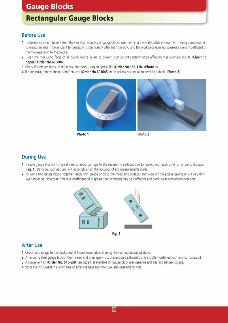
Rectangular Gauge Blocks
Gauge Blocks
Before Use1. To obtain maximum benefit from the very high accuracy of gauge blocks, use them in a thermally stable environment. Apply compensation
to measurements if the ambient temperature is significantly different from 20°C and the workpiece does not possess a similar coefficient of thermal expansion to the blocks.
2. Clean the measuring faces of all gauge blocks in use to prevent dust or dirt contamination affecting measurement results. (Cleaning paper : Order No.600006).
3. Check if there are burrs on the measuring faces using an optical flat (Order No.158-118). (Photo 1)4. If burrs exist, remove them using Ceraston (Order No.601645) or an Arkansas stone (commercial product). (Photo 2)
During Use
After Use1. Check for damage to the blocks and, if found, recondition them by the method described above. 2. After using steel gauge blocks, them clean and then apply rust prevention treatment using a cloth moistened with anti-corrosion oil.3. A convenient kit (Order No. 516-650, see page 1) is available for gauge block maintenance and cleaning before storage.4. Store the instrument in a room free of excessive heat and moisture, also dust and oil mist.
Photo 1 Photo 2
1. Handle gauge blocks with great care to avoid damage to the measuring surfaces due to impact with each other or by being dropped (Fig. 1). Damage, such as burrs, will adversely affect the accuracy of any measurements made.
2. To wring two gauge blocks together, apply thin grease or oil to the measuring surfaces and wipe off the excess leaving only a very thin layer adhering. Note that if there is insufficient oil or grease then wringing may be ineffective and block wear accelerated over time.
Fig. 1
28

Following the establishment of MTI Corporation (U.S.) in 1963, Mitutoyo has been expanding its market throughout the world. Currently, the company has R&D, manufacturing, sales, and engineering service bases in 30 countries, as well as network of distributors in some 80 countries. Mitutoyo maintains its rocksolid status as a leading global manufacturer providing services tailored to each regional society.
■ Sales
Mitutoyo Europe GmbH Mitutoyo (UK) L.td. Mitutoyo France S.A.R.L Mitutoyo America Corporation Head Offi ce
Mitutoyo Italiana S.R.L. Mitutoyo Asia Pacifi c Pte. Ltd. Regional Headquarters
Mitutoyo's global sales and service network
Mitutoyo Network
http://www.mitutoyo.co.jp/global.html
Zhengzhou Offi ceZhengzhou City, CHINAMitutoyo Leeport Metrology (Hong Kong) LimitedKwai Chung, NT, HONG KONGMitutoyo Leeport Metrology (Dongguan) Limited/ M3 Solution Center DongguanGuang Chang Road, Chong Tou ZoneMitutoyo Leeport Metrology (Dongguan) Limited – Fuzhou offi ceFuzhou City, CHINAMitutoyo Leeport Metrology (Dongguan) Limited – Changsha offi ceHunan Province, CHINAaMitutoyo Measuring Instruments (Suzhou) Co., Ltd.Suzhou, CHINA
U.S.A.Mitutoyo America CorporationAurora, U.S.A.M3 Solution Center-IllinoisAurora, U.S.A.M3 Solution Center-OhioMason, U.S.A.M3 Solution Center-MichiganMichigan, U.S.A.M3 Solution Center-CaliforniaCity of Industry, U.S.A.M3 Solution Center-North CarolinaHuntersville, U.S.A.M3 Solution Center-AlabamaHoover, U.S.A.M3 Solution Center-Washington Renton, U.S.A.M3 Solution Center-Texas Houston, U.S.A.M3 Solution Center-MassachusettsMarlborough, USA
CanadaMitutoyo Canada Inc.Mississauga, Ont., CANADAMontreal Offi ceQuebec, CANADA
ArgentinaMitutoyo Sul Americana Ltda.Argentina Branch / M3 Solution CenterBuenos Aires – ARGENTINASucursal Cordoba / M3 Solution CenterCordoba, ARGENTINA
MexicoMitutoyo Mexicana S. A. de C. V.Estado de México, MÉXICOMonterrey Offi ce / M3 Solution Center Apodaca, N.L., MÉXICOTijuana Offi ce / M3 Solution Center Tijuana, MÉXICO Querétaro Offi ce / M3 Solution Center Fraccionamiento ObservatorioAguascalientes Offi ce / M3 Solution Center Aguascalientes Ags, MÉXICOIrapuato Offi ce / M3 Solution Center Irapuato Irapuato, Gto., MÉXICO
BrazilMitutoyo Sul Americana Ltda.Head Offi ce / M3 Solution Center / FactorySuzano - SP, BRASIL
VietnamMitutoyo Vietnam Co., Ltd.Hanoi Head Offi ce / M3 Solution CenterHanoi, VIETNAMHo Chi Minh City Branch Offi ce / M3 Solution CenterHo Chi Minh City, VIETNAM
PhilippinesMitutoyo Philippines, Inc.Laguna, PHILIPPINES
IndiaMitutoyo South Asia Pvt. Ltd.Head Offi ce / M3 Solution Center New Delhi, INDIAMumbai Region Head offi ceMumbai, INDIAPune Offi ce / M3 Solution CenterPune, INDIABengaluru Region Head offi ce / M3 Solution CenterBengaluru, INDIAChennai Offi ce / M3 Solution CenterChennai, INDIAKolkata Offi ceKolkata, INDIAAhmedabad Offi ce / M3 Solution CenterAhmedabad, INDIACoimbatore Offi ceCoimbatore, INDIA
TaiwanMitutoyo Taiwan Co., Ltd. / M3 Solution Center TaipeiTaipei City TAIWAN (R.O.C.)Taichung Branch / M3 Solution Center TaichungTaichung City, TAIWAN (R.O.C.)Kaohsiung Branch / M3 Solution Center KaohsiungKaohsiung City, TAIWAN (R.O.C.)
South KoreaMitutoyo Korea CorporationHead Offi ce / M3 Solution CenterGyeonggi-do, KOREABusan Offi ce / M3 Solution CenterBusan, KOREADaegu Offi ce / M3 Solution CenterDaegu, KOREA
ChinaMitutoyo Measuring Instruments (Shanghai) Co., Ltd.Shanghai, CHINASuzhou Offi ce / M3 Solution Center China (Suzhou)Suzhou, CHINAWuhan Offi ceWuhan, CHINAChengdu Offi ceSichuan, CHINAHangzhou Offi ceHangzhou, CHINATianjin Offi ce / M3 Solution Center TianjinTianjin, CHINAChangchun Offi ceChangchun, CHINAChongqing Offi ceChongqing, CHINAQingdao Offi ce / M3 Solution Center QingdaoShandong, CHINAXi’ an Offi ceXi’ an, CHINADalian Offi ce / M3 Solution Center QingdaoDalian, CHINA
EuropeMitutoyo Europe GmbHNeuss, GERMANY
GermanyMitutoyo Deutschland GmbHNeuss, GERMANYM3 Solution Center HamburgHamburg, GERMANYM3 Solution Center BerlinBerlin, GERMANYM3 Solution Center EisenachEisenach, GERMANYM3 Solution Center IngolstadtIngolstadt, GERMANYM3 Solution Center LeonbergLeonberg, GERMANYMitutoyo-Messgeräte Leonberg GmbHLeonberg, GERMANY
U.K.Mitutoyo (UK) Ltd.Hampshire UNITED KINGDOMM3 Solution Center CoventryWarwickshire, UNITED KINGDOMM3 Solution Center HalifaxWest Yorkshire, UNITED KINGDOMM3 Solution Center East KilbrideEast Killbride, UNITED KINGDOM
FranceMitutoyo FranceParis, FRANCEM3 Solution Center LYONSaint-Priest, FRANCEM3 Solution Center STRASBOURGGeispolsheim, FRANCEM3 Solution Center CLUSESScionzier, FRANCEM3 Solution Center TOULOUSEToulouse, FRANCEM3 Solution Center RENNESRennes, FRANCE
ItalyMitutoyo ITALIANA S.r.l.Lainate (MI), ITALYM3 Solution Center BOLOGNAAnzola Emilia (BO), ITALYM3 Solution Center CHIETIRocca S. Giovanni (CH), ITALYM3 Solution Center PADOVAMestrino (PD), ITALY
NetherlandsMitutoyo Nederland B.V.KW Veenendaal, THE NETHERLANDS
BelgiumMitutoyo Belgium N.V.Kruibeke, BELGIUM
SwedenMitutoyo Scandinavia ABUpplands Väsby, SWEDENM3 Solution Center AlingsåsAlingsås, SWEDENM3 Solution Center VärnamoVärnamo, SWEDEN
FinlandMitutoyo Scandinavia Aktiebolag Finnish BranchPirkkala, FINLAND
SwitzerlandMitutoyo Schweiz AGUrdorf, SWITZERLANDMitutoyo Suisse SAYverdon-les Bains, SWITZERLAND
PolandMitutoyo Polska Sp.z o.o.Wroclaw, POLAND
Czech RepublicMitutoyo Cesko, s.r.o.Teplice, CZECH REPUBLICM3 Solution Center Ivančice Ivančice, CZECH REPUBLICM3 Solution Center Ostrava MošnovMošnov, CZECH REPUBLIC
HungaryMitutoyo Hungária Kft.Budapest, HUNGARY
RomaniaMitutoyo Romania SRLOTOPENI-ILFOV, ROMANIAShowroom in BrasovBrasov-Judetul Brasov, ROMANIA
Russian FederationMitutoyo RUS LLCMoscow, RUSSIAN FEDERATION
AustriaMitutoyo Austria GmbHTraun, AUSTRIA
SingaporeMitutoyo Asia Pacifi c Pte. Ltd.Head Offi ce / M3 Solution CenterSINGAPORE
MalaysiaMitutoyo (Malaysia) Sdn. Bhd.Kuala Lumpur Head Offi ce / M3 Solution CenterSelangor, MALAYSIAPenang Branch offi ce / M3 Solution CenterPenang, MALAYSIAJohor Branch offi ce / M3 Solution CenterJohor, MALAYSIA
IndonesiaPT. Mitutoyo IndonesiaHead Offi ce / M3 Solution CenterBekasi, INDONESIA
ThailandMitutoyo (Thailand) Co., Ltd.Bangkok Head Offi ce / M3 Solution CenterBangkok, THAILANDChonburi Branch / M3 Solution CenterChonburi , THAILANDAmata Nakorn Branch / M3 Solution CenterChonburi, THAILAND
Europe
Americas
Southeast and South Asia
East Asia
29
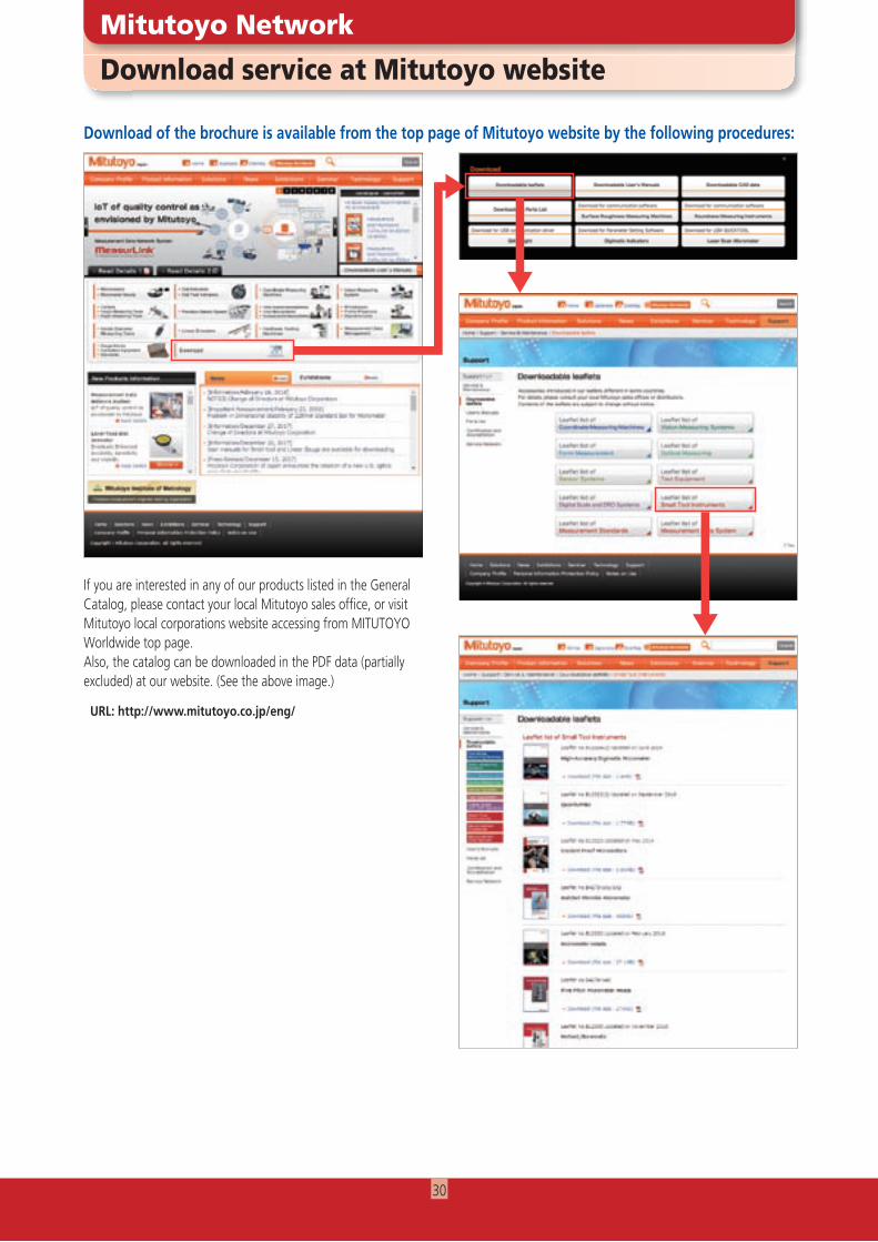
Download of the brochure is available from the top page of Mitutoyo website by the following procedures:
Download service at Mitutoyo website
Mitutoyo Network
If you are interested in any of our products listed in the General Catalog, please contact your local Mitutoyo sales offi ce, or visit Mitutoyo local corporations website accessing from MITUTOYO Worldwide top page.Also, the catalog can be downloaded in the PDF data (partially excluded) at our website. (See the above image.)
URL: http://www.mitutoyo.co.jp/eng/
30

NOTE
31

154
1810
(4)A
-(CH)
NE, P
rinte
d in
Japa
n
Coordinate Measuring Machines
Sensor Systems
Vision Measuring Systems
Test Equipmentand Seismometers
Form Measurement
Digital Scale and DRO Systems
Optical Measuring
Small Tool Instrumentsand Data Management
http://www.mitutoyo.co.jp/global.html
Find additional product literature and our product catalogue
Mitutoyo Corporation
20-1, Sakado 1-Chome,
Takatsu-ku, Kawasaki-shi,
Kanagawa 213-8533, Japan
T +81 (0) 44 813-8230
F +81 (0) 44 813-8231
http://www.mitutoyo.co.jp
Whatever your challenges are, Mitutoyo supports you from start to finish.
Mitutoyo is not only a manufacturer of top quality measuring products but one that also offers qualified support for the lifetime of the equipment, backed up by comprehensive services that ensure your staff can make the very best use of the investment.
Apart from the basics of calibration and repair, Mitutoyo offers product and metrology training, as well as IT support for the sophisticated software used in modern measuring technology. We can also design, build, test and deliver bespoke measuring solutions and even, if deemed cost-effective, take your critical measurement challenges in-house on a sub-contract basis.
Note: Product illustrations are without obligation. Product descriptions, in particular any and all technical specifications, are only binding when explicitly agreed upon.MITUTOYO and MiCAT are either registered trademarks or trademarks of Mitutoyo Corp. in Japan and/or other countries/regions. Other product, company and brand names mentioned herein are for identification purposes only and may be the trademarks of their respective holders.
Our products are classified as regulated items under Japanese Foreign Exchange and Foreign Trade Law. Please consult us in advance if you wish to export our products to any other country.If the purchased product is exported, even though it is not a regulated item (Catch-All controls item), the customer service available for that product may be affected. If you have any questions, please consult your local Mitutoyo sales office.