the use of simulation to de-risk maritime uav operations meeting proceedings/rto... · the use of...
TRANSCRIPT

RTO-MP-AVT-146 13 - 1
UNCLASSIFIED/UNLIMITED
UNCLASSIFIED/UNLIMITED
The Use of Simulation to De-risk Maritime UAV Operations
Mr Ian Cox Senior Consultant, Systems Engineering & Assessment Ltd
SEA House, Bristol Business Park Bristol, BS16 1EJ
UK
Mr Jeremy Howitt Assistant Technical Director – Air Systems, QinetiQ
Cody Technology Park, Ively Road Farnborough, Hampshire, GU14 0LX
UK
Dr John Duncan Head of Simulation Based Acquisition, Technical Enabling Services – Sea Systems Group
Defence Procurement Agency, Rowan 0 #8014 MoD Abbey Wood, Bristol, B34 8JH
UK
ABSTRACT
The UK Ship/Air Interface Framework (SAIF) project has developed a networked simulation architecture for the purposes of studying the dynamic interface between an air vehicle and the ship from which it operates. The SAIF project has enhanced the simulation technology developed for the 13 nation NATO/PfP Interoperability and Re-Use Study (NIREUS), and has initially been aimed at developing a simulation system capable of accurately predicting the Ship/Helicopter Operating Limits (SHOLs) for a helicopter operating from a wide variety of current and future ship platforms. Since the SAIF architecture is independent of any particular ship or aircraft type, it has the potential to assess the operational performance of fixed or rotary wing Maritime UAV (MUAV) concepts in the key launch and recovery phases. This paper summarises the findings of a joint Systems Engineering and Assessment (SEA) and QinetiQ feasibility study into the potential application of the SAIF architecture for MUAV simulation experiments. The study concluded that the use of simulation offers a powerful methodology for developing ship/MUAV operating limits in a flexible and cost effective manner. The use of a federated architecture also provides the opportunity to develop a collaborative simulation architecture with partner nations for use in MUAV studies.
1.0 INTRODUCTION
The safe operating limits of aircraft from naval vessels are currently determined either by manned flight trials, or by estimation by experienced aircraft operators. The use of simulation to study the dynamic
Cox, I.; Howitt, J.; Duncan, J. (2007) The Use of Simulation to De-risk Maritime UAV Operations. In Platform Innovations and System Integration for Unmanned Air, Land and Sea Vehicles (AVT-SCI Joint Symposium) (pp. 13-1 – 13-16). Meeting Proceedings RTO-MP-AVT-146, Paper 13. Neuilly-sur-Seine, France: RTO. Available from: http://www.rto.nato.int/abstracts.asp.

The Use of Simulation to De-risk Maritime UAV Operations
13 - 2 RTO-MP-AVT-146
UNCLASSIFIED/UNLIMITED
UNCLASSIFIED/UNLIMITED
interface between the air vehicle, the ship and the environment in which they both operate offers significant potential benefits, in terms of the cost, flexibility and time to produce a new set of operating limits. However, using modelling and simulation to analyse this complex subject provides a unique set of challenges.
The Ship/Air Interface Framework (SAIF) project commenced in 2003, and has developed a networked simulation architecture for the purposes of studying the dynamic interface between an air vehicle and the ship from which it operates. The framework utilises the High Level Architecture (HLA), whereby the simulation is split into several ‘federate’ models, separate from a core aircraft flight simulator. The federate models can be run on remote computers, and provide functionality such as the real-time representation of the ship motion characteristics and airwake flow field. The project sponsors are the UK Defence Procurement Agency Technical Enabling Services – Sea Systems Group (TES-SSG) and the Directorate of Equipment Capability – Above Water Effects (DEC-AWE).
The initial stages of the project have concentrated upon developing a networked version of the Merlin helicopter flight simulator, based at the Royal Naval Air Station (RNAS) Culdrose. The main aim of modifying the Merlin simulator is to produce a high-fidelity system capable of accurately predicting the Ship/Helicopter Operating Limits (SHOLs) for the aircraft operating from a wide variety of current and future ship platforms. The use of simulation in this field provides a more flexible and cost effective method of generating SHOLs, and when used in combination with first-of-class flight trials, will help to maximise the aircraft’s operating envelope. SHOLs are comprised of a set of operating envelopes that describe the wind speed and relative wind direction conditions within which an aircraft can safely operate from a ship. The SHOL is normally displayed in the form of a polar plot, as shown in Figure 1. SHOLs are usually provided for different aircraft operating weights, for a certain set of conditions (e.g. day or night operations, using a certain approach path to the flightdeck).
0
330
300
270
240
210
180
150
120
90
60
30
10
5040
3020
Wind over deckvelocity (kts)
Relative winddirection (degrees)
Area inside the blue line isinside the SHOL - i.e.
acceptable pilot workloadand air vehicle performance
levels for launch andrecovery.
Figure 1: SHOL plot indicating safe limits for relative wind velocity and direction
Since the SAIF architecture is independent of any particular ship or aircraft type, it has the potential to assess the operational performance of Maritime Unmanned Air Vehicle (MUAV) concepts in the key

The Use of Simulation to De-risk Maritime UAV Operations
RTO-MP-AVT-146 13 - 3
UNCLASSIFIED/UNLIMITED
UNCLASSIFIED/UNLIMITED
launch and recovery phases. This paper summarises the findings of a study carried out to assess the feasibility and benefits of modelling MUAV operations within the SAIF architecture, considering not only the simulation technology, but also the challenges of developing a set of Ship/MUAV operating limits without a pilot in the loop.
2.0 STUDY BACKGROUND
2.1 NIREUS VTOL UAV Simulation The NATO/Partnership for Peace (PfP) Interoperability and Re-Use Study (NIREUS), was a 13-nation project to apply the HLA standards to investigate multinational distributed simulation for system design and acquisition. The NIREUS test case concerned the development of a distributed simulation of Vertical Take-Off and Landing (VTOL) air vehicle operations from ships, initially focusing on the automated recovery of MUAVs, but also addressing conventional manned aircraft. The test case demonstrated the interoperability of different nations’ simulations and domain experts, and assessed the interoperability of the platforms and systems they represent [1,2]. In order to foster the interoperability of air vehicle simulations and ship air wake models within the NIREUS framework, a common generic interface structure was developed, including common middleware software, support and verification tools, as shown in Figure 2. A generic rotorcraft MUAV model was developed for the simulation in the UK, with ship models provided by the participating nations. The resulting federation successfully demonstrated the automatic recovery of a MUAV onto various nations’ ships under a range of environmental conditions, during a set of simulation trials in 2001. In particular, the project demonstrated that the use of separate air vehicle and ship airwake federate models was a valid approach. This served as a valuable in exercise in de-risking the simulation technologies required to generate an accurate ship/air interface assessment tool.
Ship
MotionShip
Motion
Ship MotionForward Prediction
Ship MotionForward Prediction
Ship MotionForward Prediction
Ship MotionForward Prediction
ShipMotionShip
Motion
ShipINS
ShipINS
ShipMotionShip
Motion
Ship MotionForward Prediction
Ship MotionForward Prediction
Ship MotionForward Prediction
Ship MotionForward Prediction
ShipMotionShip
Motion
ShipINS
ShipINS
Approach/LandingAlgorithm
Approach/LandingAlgorithm
TrackingSensors
TrackingSensors
TouchdownDynamics
TouchdownDynamics
Approach/LandingAlgorithm
Approach/LandingAlgorithm
TrackingSensors
TrackingSensors
TouchdownDynamics
TouchdownDynamics
Air VehicleAir Vehicle
Air EffectsServices
Air EffectsServices
Air VehicleAir Vehicle
Air EffectsServices
Air EffectsServices
ManagementFederate
ManagementFederate
VisualizationVisualizationData
CollectionTool
DataCollection
Tool
Run Time InfrastructureRun Time Infrastructure
ManagementFederate
ManagementFederate
VisualizationVisualizationData
CollectionTool
DataCollection
Tool
Run Time InfrastructureRun Time Infrastructure
Figure 2: Multi-national NIREUS concept demonstration federation
2.2 The SAIF Architecture The SAIF project took the NIREUS simulation and developed it for the purposes of predicting SHOLs for manned aircraft, via funding from TES-SSG under the VIrtual Ships Technology Arrangement (VISTA). An HLA-based federated approach has been maintained, allowing the rapid integration and modification of the individual models within the simulation [3,4]. The SAIF architecture is comprised of the following six federate models, and is shown in Figure 3:

The Use of Simulation to De-risk Maritime UAV Operations
13 - 4 RTO-MP-AVT-146
UNCLASSIFIED/UNLIMITED
UNCLASSIFIED/UNLIMITED
• Environment Federate: Publishes data on the wind speed and direction, sea state, wave spectra, time of day and visibility levels to the federation;
• Ship Motion Federate: Calculates in real-time the six degree-of-freedom motion of the ship, either by using a pre-recorded time history file or by calculating the response to the individual wave sinusoids published by the Environment Federate;
• Ship Airwake Federate: Calculates the three-dimensional airflow velocity vector at various sample points around the air vehicle. A grid of normalised airwake flow perturbation and turbulence intensity values around the ship is calculated offline using Computational Fluid Dynamics (CFD) methods. The position of the air vehicle relative to the ship is then used to access the look-up tables, and calculate the airflow velocity vectors at the sample points, which are scaled by the wind over deck velocity. The airflow data is then fed back to the air vehicle model for use within its internal flight dynamics calculations;
• Landing Aids Federate: Controls the functionality of the various ship-borne visual landing aids systems used to support aircraft operations;
• Visualisation Federate: Provides a dynamic visualisation of the simulation from multiple user-selected viewpoints;
• Air Vehicle Federate: Provides a simulation of the flight dynamics of the air vehicle. In the first example of the application of SAIF, this functionality is provided by the networked version of the Merlin helicopter flight simulator.
EnvironmentSea Surface, wind speed & direction,
time of day, fog level
Ship MotionReal time six degree of freedom
Ship AirwakeAirflow velocity vectors in three axes
HLA Run Time Infrastructure
Landing AidsControls ship visual landing aids
VisualisationMultiple viewpoints of simulation
Air VehicleFlight simulator and data logging
Individual federate model (separate from core flight simulator)
Aircraft flight simulation
Figure 3: SAIF architecture split into six federate models
2.3 SAIF Test and Validation The first piloted assessment of the SAIF configuration was conducted at the Merlin Training Facility at Culdrose during August 2004. The overall strategy adopted for the trials was to conduct an assessment of the SHOL for the operation of a Merlin helicopter from a Type 23 Frigate in order to collect sufficient data to compare with the real SHOL. Pilots and Flight Test Engineers from the Rotary Wing Test Squadron (RWTS) at Boscombe Down have been used throughout the project to provide an experienced assessment of the validity of the simulation. Several improvements were made to the system following these initial trials, and the Merlin/Type 23 validation test points were re-flown in the simulator using a RWTS test pilot and an experienced Royal Navy (RN) Squadron pilot in 2005. Analysis of the results showed that

The Use of Simulation to De-risk Maritime UAV Operations
RTO-MP-AVT-146 13 - 5
UNCLASSIFIED/UNLIMITED
UNCLASSIFIED/UNLIMITED
there was a good match between the simulated and real data, and in the vast majority of cases the difference between the simulated and real pilot workload ratings using the Deck Interface Pilot Effort Scale (DIPES) was one or less. The causal factors (e.g. torque or pedal limits being reached) were also well matched between the simulation and real results [5].
Given these encouraging results, simulator trials were flown in September 2005 using the SAIF configured Merlin simulator to develop an indicative SHOL for the Merlin operating from the new RN Type 45 destroyer. It is believed that this capability is a world-first in using simulation for the development of an indicative set of operating limits for a new ship/helicopter combination. The results have been briefed to DEC-AWE, and serve as a far more detailed estimation of the likely operational envelope than has to date been possible to produce prior to a new ship type being launched. At this stage, the use of the simulation results to influence the Merlin/Type 45 flight test programme will be limited, pending the completion of further validation studies involving the application of the SAIF models to other known ship and aircraft types. Further successful validation studies where the results of simulation compare well with flight test data will increase the confidence level in the predicted SHOL for Merlin/Type 45.
3.0 THE APPLICATION OF SAIF TO MUAV OPERATIONS
3.1 Requirements for MUAV simulation The section details some of the key requirements for a MUAV simulation capability, to evaluate the performance of different air vehicle designs within the boundaries of ship/air interface issues. The simulation should be able to discriminate between competing designs, and provide information on the key cost, capability and risk drivers. In addition, the use of simulation offers the potential benefit of testing in a wide variety of simulated weather and environmental conditions, which may not be available during limited trials time at-sea. If the validation status of the simulation is sufficiently high, then the scope of at-sea tests may be reduced to particular areas of interest within the operational envelope, thus reducing costly trials time.
3.1.1 Performance comparison of air vehicle architectures
The motivation for developing the SAIF environment to address MUAV operations arises from the growing consideration of such vehicles for future naval aviation roles and missions. A wide variety of vehicle types are being considered to fulfil the demanding requirements of naval operations, including:
• Fixed-wing – e.g. Boeing ScanEagle;
• Helicopter – e.g. Northrop-Grumman Fire Scout;
• Tilt-rotor – e.g. Bell Eagle Eye;
• Amphibious – e.g. Aeromarine Warrior Gull.
A simulation system should be suitably flexible so that it can evaluate the strengths and weaknesses of these competing vehicle architectures using the same set of test conditions. For example, the relative vehicle responses to the turbulent airwake conditions found in the lee of a ship’s superstructure may be a key discriminator in determining how easy an MUAV design may be to operate from a ship. The simulation should therefore consistently apply the effects of the air wake to the flight dynamics model of all candidate vehicles, regardless of their configuration.
3.1.2 Development of operating limits for a MUAV
The use of SAIF in developing predictive SHOLs for manned aircraft has relied heavily upon the subjective assessments of pilot workload provided by an experienced test pilot, using approved rating

The Use of Simulation to De-risk Maritime UAV Operations
13 - 6 RTO-MP-AVT-146
UNCLASSIFIED/UNLIMITED
UNCLASSIFIED/UNLIMITED
scales. The DIPES rating is used in the UK for SHOL trials in order to assess if the pilot workload to recover/launch an aircraft to/from a ship is at an acceptable level for a fleet pilot. Figure 4 shows the decision tree that is used to determine a rating between one and five, where a rating above three indicates an unacceptably high workload level. Along with the numerical rating, a letter descriptor is added to specify the key causal factors for the rating score (e.g. H = Height Control, Y = Yaw Control). Post trials analysis of engine torque and tail rotor pitch values are also evaluated using data logged during the flight to determine if limits for these parameters have been exceeded.
DECK INTERFACE PILOT EFFORT SCALE (DIPES) EFFORT EXPLANATION DIPESSlight to
Moderate Reasonable pilot compensation required. Tracking and positioning accuracy is consistently maintained throughout the operation. Fleet pilots will have enough spare capacity to conduct ancillary tasks (eg. radio, Tq gauge, checks).
1
Considerable
Significant pilot compensation required. Tracking and positioning accuracy are occasionally exceeded during peaks in ship motion, sea spray or turbulence. Fleet Pilots will have difficulty conducting ancillary tasks (eg. Radio, Tq gauge, checks).
2
Highest tolerable
Highest tolerable pilot compensation required. Repeated safe shipboard launch/recovery operations are achievable. Fleet pilots will be able to keep up with task requirements but no more. Degraded operations (ship or aircraft) are likely to cause fleet pilot effort to become unacceptable. These points define the release limits recommended by (DERA).
3
Excessive Excessive pilot compensation required. Fleet Pilots will be purely reacting to external influences rather than anticipating them. Accuracy is poor in one or more axes. Fleet pilots under operational conditions could not consistently repeat these evolutions safely.
4
Dangerous
Extreme pilot compensation required. Repeated safe evolutions are not possible even under controlled test conditions with fully proficient crews. 5
Note: Each DIPES rating should be given one or more suffixes to describe the cause(s) of the increased workload:
Pitch control: P Height control: H Turbulence: T Windscreen W Roll control: R F/Aft positioning: F Deck Motion: D Spray S Yaw control: Y Lateral positioning: L Visual Cues: V Torque Control Q
Yes
UNACCEPTABLE
Yes
Is a successful recovery likely?
No
Have fleet pilot limits been reached?
No
ACCEPTABLE
No Would a fleet pilot be
consistently safe?
Would fleet pilot effort be
moderate or less?
No
Yes
FLEET / OPERATIONAL
PILOT WORKLOAD
Yes
Figure 4: DIPES decision tree for pilot workload assessment
Given that a MUAV is likely to have a semi-automatic (or possibly fully autonomous) landing mode, during which a pilot is not in direct control of the aircraft, the use of the DIPES rating scale would not be relevant. Alternative factors will need to be analysed in order to evaluate the safe operating limits of the MUAV. These may include:
• Accuracy of the recovery to the flightdeck of a moving ship in different conditions;
• Evaluation of the air vehicle control system workload levels (i.e. the frequency and magnitude of control inputs required for an accurate recovery), and the proximity to the limits of air vehicle and control system limits during recovery;
• Time taken to recover the air vehicle from a set distance from the ship;
The Use of Simulation to De-risk Maritime UAV Operations
RTO-MP-AVT-146 13 - 7
UNCLASSIFIED/UNLIMITED
UNCLASSIFIED/UNLIMITED
• Amount of operator input required to safely launch and recover the air vehicle;
• Proximity of the air vehicle to the ship’s superstructure during launch and recovery.
3.1.3 Analysis of MUAV command and control issues
The use of simulation early in the MUAV development cycle may aid the requirements capture process, and allow prototype architectures and designs to be quickly evaluated. One particular area that may be de-risked in this way is the design of the Man-Machine Interface (MMI) for an MUAV operator. The remote ground (ship) control system used to provide command input to the MUAV must provide a high degree of situational awareness and require a low level of workload for any human operator. Several different MMI designs may be tested using simulation, prior to any firm decision on the type of air vehicle platform. An early capability for operators to define concepts of operation may also build confidence prior to the deployment of such radically different technologies.
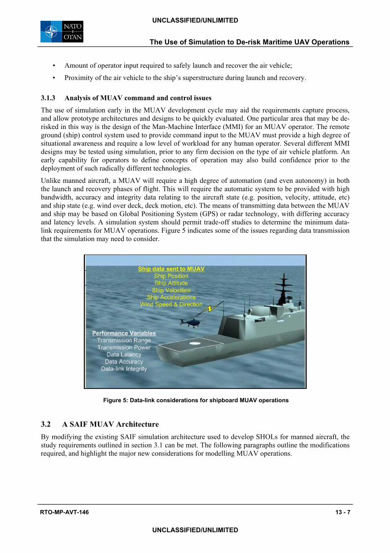
Unlike manned aircraft, a MUAV will require a high degree of automation (and even autonomy) in both the launch and recovery phases of flight. This will require the automatic system to be provided with high bandwidth, accuracy and integrity data relating to the aircraft state (e.g. position, velocity, attitude, etc) and ship state (e.g. wind over deck, deck motion, etc). The means of transmitting data between the MUAV and ship may be based on Global Positioning System (GPS) or radar technology, with differing accuracy and latency levels. A simulation system should permit trade-off studies to determine the minimum data-link requirements for MUAV operations. Figure 5 indicates some of the issues regarding data transmission that the simulation may need to consider.
Figure 5: Data-link considerations for shipboard MUAV operations
3.2 A SAIF MUAV Architecture By modifying the existing SAIF simulation architecture used to develop SHOLs for manned aircraft, the study requirements outlined in section 3.1 can be met. The following paragraphs outline the modifications required, and highlight the major new considerations for modelling MUAV operations.

The Use of Simulation to De-risk Maritime UAV Operations
13 - 8 RTO-MP-AVT-146
UNCLASSIFIED/UNLIMITED
UNCLASSIFIED/UNLIMITED
3.2.1 Federation Design
A candidate architecture for a SAIF MUAV federation is shown in Figure 6. Where possible, the architecture makes maximum usage of the federate models developed for the SAIF SHOL project. New federates are added to the architecture only where appropriate.
EnvironmentSea Surface, wind speed & direction,
time of day, fog level
Ship MotionReal time six degree of freedom
Ship AirwakeAirflow velocity vectors in three axes
HLA Run Time Infrastructure
VisualisationMultiple viewpoints of simulation
MUAVFlight dynamics and data logging
Existing SAIF federate model
New MUAV federate
Recovery SystemPhysical system and/or
ship-MUAV data link
UAV ControllerCommand input to MUAV
New MUAV flight dynamics federate
Figure 6: SAIF MUAV architecture combines SHOL models with new federates
The federates re-used from the SHOL federation (shown in green in Figure 6) are:
• Environment Federate: Publishes the environment data as per the SHOL federation;
• Ship Motion Federate: Calculates the six degree-of-freedom motion of the ship from which the MUAV operates (ship type to be confirmed);
• Ship Airwake Federate: Calculates the airflow velocity vectors at the MUAV sample points. Improvements made to the airwake federate as part of the SAIF SHOL programme can be easily fed through to the MUAV federation. The internal airwake model Dynamic Link Library (DLL) around which the federate is constructed may need to be modified to meet the specific requirements of a MUAV platform (this is discussed at section 3.2.2);
• Visualisation Federate: Provides a dynamic visualisation of the simulation. Visual models of the MUAV and possibly the recovery system will be added to the visualisation as required.
Three new federate models are required for the SAIF MUAV federation:
• Launch/Recovery System Federate: This would provide a model of any physical launch/recovery system (e.g. catapult, net, harpoon, sky-hook etc.), and/or provide information on the ships relative position to the MUAV, replicating a GPS or radar-based recovery system. The accuracy and latency of the data provided to the MUAV from this federate could be varied to assess the required level of data fidelity for particular MUAV platforms;
• UAV Controller Federate: This would provide a model of the MMI for a UAV Controller to input basic commands to the MUAV. The format and content of the data passed to the UAV may follow any NATO standard message protocols developed for this purpose. The level of

The Use of Simulation to De-risk Maritime UAV Operations
RTO-MP-AVT-146 13 - 9
UNCLASSIFIED/UNLIMITED
UNCLASSIFIED/UNLIMITED
complexity of this federate would depend upon the level of autonomy included within the MUAV model;
• MUAV Federate: This model provides the simulation of the flight dynamics of the MUAV. As with the SHOL air vehicle federate, this model will utilise the airwake data published by the airwake federate and also act as the central data logging point for simulation data. The federate will also take commands from the UAV controller. A generic model would also be expected to contain the following features:
• A representation of the MUAV undercarriage design, in order to accurately represent the interactions between the ship and MUAV upon touchdown and at the moment of take-off;
• A sufficiently detailed autopilot model, to transfer high-level commands into control surface and propulsion system inputs, thus replacing the role of the pilot in the SHOL simulation.
The federated approach allows for the development of the new federate models to be carried out independently, against a known interface specification. The existing SAIF SHOL federates would provide the backbone of a test federation, and the new models could be rapidly integrated and tested as they are developed. The final MUAV federation is also not reliant upon access to a heavily utilised manned aircraft flight simulator for testing and trials, as in the case of the SHOL simulation.
Since a networked architecture using the HLA standards is the suggested route for the MUAV system, this opens up the possibility of running the federation across a Wide Area Network (WAN), with federate models located at different sites. However, careful consideration of the bandwidth required by the simulation and the potential effects of data latency will be required. A lower risk solution would be to co-locate all of the MUAV federate models within a Local Area Network (LAN) at a mutually convenient site for experimental purposes.
3.2.2 Air Vehicle Models
Two different approaches may be used to provide the model for the MUAV federate. In the first instance, a generic model (or subset of models) could be developed that effectively parameterise the flight dynamics characteristics of different air vehicle designs. For example, parameters such as aircraft dimensions, mass, inertia and manoeuvre characteristics, lift-to-drag ratio, engine performance and control system responsiveness may be modified in a generic model to represent different MUAV platforms. These parameters could be evaluated using data supplied by an air vehicle manufacturer, open source information, or by making informed assumptions. A generic air vehicle autopilot module could also be tuned to represent the control characteristics of the different designs. This approach may provide a more cost-effective approach to simulating different MUAV designs, at the potential expense of reduced fidelity where data is not available. A generic air vehicle model would also be suitable for the early investigation of UAV Controller MMI issues.
An alternative approach may be to re-use an existing standalone type-specific air vehicle flight dynamics model within the federation. This could be achieved by developing an HLA ‘wrapper’ interface to the existing model, which handles the transmission of data between the HLA federation and the internal functions of the model. The existing standalone MUAV model may already be developed and validated by the air vehicle manufacturer as part of the vehicle design process. By using a model with a successful previous validation and test history, the validation level of the overall federated simulation solution may be enhanced.
For all approaches to MUAV modelling, the correct interaction between the air vehicle and ship airwake representation is key to providing an accurate simulation. This has been proven through extensive testing using the SAIF SHOL configuration. The scale lengths and turbulence intensities within the current SAIF airwake model structure are optimised for integration with a full-scale helicopter rotor. It is considered

The Use of Simulation to De-risk Maritime UAV Operations
13 - 10 RTO-MP-AVT-146
UNCLASSIFIED/UNLIMITED
UNCLASSIFIED/UNLIMITED
that this structure will still be appropriate for the medium/large UAVs (e.g. Fire Scout), but that modification may be required for smaller UAVs (e.g. ScanEagle). In particular, this class of aircraft may require a CFD flow solution to be generated using a finer computational grid. This would incur a slight increase in time and cost to generate the CFD solution, but it is not considered to be a major issue. The current airwake model as applied in the SAIF programme would be immediately useable with, at most, modest changes to its interfaces and content.
3.2.3 Air Vehicle Command and Control
The control of a MUAV from the ground (or in this case the ship) raises critical questions regarding the interfaces between the operator and the UAV control system (UCS). NATO Standardisation Agreement 4586 was conceived in 1998 to standardise UAV control system interfaces via an Interface Control Definition (ICD) [6]. The aim of the STANAG is to promote interoperability between one or more ground stations, UAVs and their payloads, and the Command, Control, Communication, Computers and Intelligence (C4I) network, by using standard interfaces. Two new interfaces are defined within the STANAG:
• Data Link Interface (DLI): between the UAV and the UCS;
• Command & Control Interface (CCI): between the UCS and the C4I network.
Figure 7 indicates how the UAV Controller and MUAV federates may be configured using a STANAG 4586 compliant methodology. The operator of the UAV would interact with the UAV Controller federate using a Human Computer Interface (HCI), which is designed to provide the operator with relevant mission management information and control input. The HCI is then linked with the Core UCS that converts operator commands into messages within the STANAG DLI format. These messages can then be published via the HLA network. The MUAV federate would subscribe to the messages via its own DLI, and then de-code them into air vehicle commands for the flight dynamics model, via a Vehicle Specific Module (VSM). This would allow the DLI within the MUAV federate to be common for all air vehicle types.
The STANAG DLI may also need to be extended to cater for specific maritime operational issues. For example, if the MUAV operator onboard a ship deems that conditions would be dangerous for the MUAV to recover to the ship, then a ‘wave-off’ command may be issued to the air vehicle telling it to abort its approach. Details of the STANAG will have to be studied to ensure that all MUAV operational modes can be utilised.

The Use of Simulation to De-risk Maritime UAV Operations
RTO-MP-AVT-146 13 - 11
UNCLASSIFIED/UNLIMITED
UNCLASSIFIED/UNLIMITED
HLA Run Time Infrastructure
Operator
Human Control Interface (HCI)
Data Link Interface (DLI)
Vehicle Specific Module (VSM)
Data Link Interface (DLI)
STANAG 4586 component
UAV Controller - Core UAV Control System (CUCS)
MUAV Flight Dynamics
UAV Controller federate
MUAV federate
Figure 7: SAIF MUAV Architecture can be configured following STANAG 4586 guidelines
4.0 EXPERIMENTAL DESIGN
4.1 Potential Ship/MUAV Combinations The approach taken to date with experimental design for the SAIF manned helicopter studies has been one of incremental validation, starting from a reasonably well understood baseline (e.g. Merlin/Type 23 with a time-averaged CFD flow solution) and changing just one experimental parameter at a time - i.e. ship type, air vehicle type or technology option (e.g. CFD flow solution). It is proposed that a similar evolutionary process is appropriate for MUAVs. A reasonable starting point would again be to consider operations from a Type 23 Frigate, for which there is a significant body of validation evidence both in terms of operational experience and measurements and also existing simulation data. There are two strong candidates for the initial test cases:
• Type 23 / Fixed Wing MUAV (e.g. Boeing ScanEagle): Within the UK, one of the remits of the Joint UAV Experimentation Programme (JUEP) has been to explore the utility of UAVs for maritime operations. As part of the JUEP study, a Boeing ScanEagle aircraft successfully completed 10 autonomous launch and recovery cycles from a RN Type 23 Frigate, during trials off the Scottish coast in 2006. This set of real-life tests may provide a valuable validation test case for a SAIF MUAV capability.
• Type 23 / Rotary Wing MUAV (e.g. Northrop-Grumman Fire Scout): Whilst Fire Scout has never operated from a Type 23, it is a conventional full-scale helicopter and hence represents minimum change from previous manned helicopter simulations in terms of air vehicle dynamics and airwake interaction. This would allow the simulation of new ground control system and launch/recovery system federates to be tested in an otherwise conventional and proven helicopter/ship simulation environment.
4.2 Test Methodology In common with the SAIF SHOL experiments, a set of test variables would need to be developed for a SAIF MUAV operating limits experiment. A matrix of test points would be developed, using a combination of the following factors:

The Use of Simulation to De-risk Maritime UAV Operations
13 - 12 RTO-MP-AVT-146
UNCLASSIFIED/UNLIMITED
UNCLASSIFIED/UNLIMITED
• Aircraft mass;
• Ship heading and speed;
• Sea state conditions;
• Day/night and visibility (i.e. fog or cloud) conditions;
• MUAV approach angle to the ship (i.e. standard RN approach to the port side of the ship).
A standard procedure for evaluating the MUAV performance for each test point would also be required. Again, lessons learnt from the SAIF SHOL programme can be applied to MUAV operations. A typical test point evaluation may start with the MUAV on approach to the ship at a specified separation distance, speed and height. The MUAV would then recover to the ship (either automatically or via operator command), and hold position on deck. If the MUAV is then capable of taking off without the use of a separate launching mechanism, then a take-off would be executed, and the aircraft flown to a safe separation distance from the ship. At this time, the simulation test point would be stopped, and a data log file written recording all of the parameters required for analysis. Since a UAV operator may not be required, there is a possibility that the simulation may be run in a ‘Monte-Carlo’ mode at a rate considerably higher than real-time. This offers the potential benefit of evaluating a large number of test points over a shorter period of time when compared with the manned SHOL simulation experiments.
4.3 Data Analysis As explained in section 3.1.2, definition of the key performance metrics and analysis of the data from an MUAV operating limits simulation will require careful consideration. The end goal of an intuitive set of operating limits for a MUAV must remain a key consideration, with the output of the simulation resulting in a set of wind speed and direction polar plots (see Figure 1), and possibly a set of deck motion limits (ship pitch and roll angles) within which the air vehicle can safely launch, recover and be moved around the flightdeck. Consultation with the MUAV operators will be required to develop an approved analysis methodology, with the aim of building confidence in the simulation results within the user community. As with any simulation, validation will also be highly important, and the comparison of simulation test data with real MUAV flight trials data should be made if available.
5.0 THE WAY FORWARD
Having completed a feasibility study, the next phase of the development of SAIF MUAV capability is to follow good system engineering practises and develop a User Requirements Document (URD) for the simulation, gaining input from the key project stakeholders. A simulation System Requirements Document (SRD) can then be produced, indicating how the simulation can meet the needs of the various stakeholders. Once the URD and SRD have been approved the simulation can then be designed and developed, making maximum re-use of the existing SAIF architecture. It is estimated that an initial SAIF MUAV simulation capability would be available within 6-12 months of the start of the project.
By adopting a networked approach using HLA, the opportunity exists to easily plug-in different federate models to the architecture using a common interface. The SAIF SHOL programme has shown that new ship motion, airwake and landing aids models can be rapidly integrated within the framework. The HLA standards state that a Federation Object Model (FOM) is developed for each simulation. The FOM describes the data transmitted via the HLA network, to which each federate model can subscribe to, or publish. By developing a common FOM that is open and available to all NATO nations, a collaborative simulation project may be achieved, whereby partner nations could assess their MUAV designs within a common framework. Figure 8 shows how a library of federate models could potentially be developed, all using the common framework.

The Use of Simulation to De-risk Maritime UAV Operations
RTO-MP-AVT-146 13 - 13
UNCLASSIFIED/UNLIMITED
UNCLASSIFIED/UNLIMITED
EnvironmentSea Surface, wind speed & direction,
time of day, fog level
Ship MotionReal time six degree of freedom
HLA Run Time Infrastructure
VisualisationMultiple viewpoints of simulation
Recovery SystemPhysical system and/or
ship-MUAV data link
Ship AirwakeAirflow velocity vectors in three axes
UAV ControllerCommand input to MUAV(STANAG 4586 compliant)
MUAVFlight dynamics and data logging
Additional federate models from NATO Nations can be plugged into federation
Figure 8: Open architecture supports collaborative simulation projects
6.0 CONCLUSIONS
The conclusions of the feasibility study into the potential application of the SAIF architecture for MUAV simulation experiments are:
• The SAIF architecture provides a suitable environment in which to study the ship/air interface issues associated with MUAV operations from naval vessels. A large proportion of the SAIF SHOL architecture can be readily ported into a MUAV system, and the two systems would mutually benefit from further technology enhancements.
• The benefits of using SAIF to study MUAV operations at an early stage in their lifecycle are:
• The ability to investigate the required levels of accuracy and latency for the transmission of data from the ship to the MUAV by a recovery system, ahead of any system selection;
• The early de-risking of ship integration issues such as the required levels of operator interaction and vehicle control, the design of MUAV capture/recovery aids and flight deck safety;
• The opportunity to develop methodologies for producing operating limits and flight clearances for MUAV operations from naval vessels;
• The opportunity to develop a collaborative simulation architecture with partner nations for use in MUAV studies.
• Simulating the test scenarios from the JUEP ScanEagle/Type 23 trials, and comparing the simulated and flight test data could achieve validation of a SAIF MUAV system.
In summary, the use of simulation offers a powerful methodology for developing ship/MUAV operating limits in a flexible and cost effective manner.

The Use of Simulation to De-risk Maritime UAV Operations
13 - 14 RTO-MP-AVT-146
UNCLASSIFIED/UNLIMITED
UNCLASSIFIED/UNLIMITED
7.0 REFERENCES
[1] Woodrow, I., Spilling, D., McCallum, A (2002). The Interoperable Simulation of Air Vehicles and Ship Air Wakes within a Multinational Simulation Framework. 2nd European Simulation Interoperability Workshop, June 2002, London, UK, Paper No. 02E-SIW-047 (http://www.sisostds.org).
[2] White, S., Reading, R. (2001). NATO/PfP HLA Federation of VTOL Operations Supporting Simulation Based Acquisition. 1st European Simulation Interoperability Workshop, June 2001, London, UK, Paper No. 01E-SIW-034 (http://www.sisostds.org).
[3] Cox, I., Turner, G., Duncan, J. (2005). Applying a Networked Architecture to the Merlin Helicopter Simulator. Royal Aeronautical Society conference “Multi-role and Networked Simulation, Networking of Simulators – For Better or Worse?” London, May 2005.
[4] Cox, I., Duncan, J. (2006). The Simulation of the Ship/Air Interface. Maritime Systems and Technology (MAST) Conference, Nice, September 2006.
[5] Turner, G., Clark, W., Cox, I., Finlay, B., Duncan, J. (2006) Project SAIF – Assessment of Ship Helicopter Operating Limits Using the Merlin Helicopter Simulator. American Helicopter Society 62nd Annual Forum, Phoenix, Arizona, May 2006.
[6] Cummings, M.L., Platts, J.T., Sulmistras, A. Human Performance Considerations in the Development of Interoperability Standards for UAV Interfaces. Moving Autonomy Forward Conference, Lincoln, UK, 2006.

The Use of Simulation to De-risk Maritime UAV Operations
RTO-MP-AVT-146 13 - 15
UNCLASSIFIED/UNLIMITED
UNCLASSIFIED/UNLIMITED
8.0 ACRONYMS AND ABBREVIATIONS
C4I Command, Control, Communication, Computers and Intelligence
CCI Command and Control Interface
CFD Computational Fluid Dynamics
DEC-AWE Directorate of Equipment Capability – Above Water Effects
DIPES Deck Interface Pilot Effort Scale
DLI Data Link Interface
DLL Dynamic Link Library
FOM Federation Object Model
GPS Global Positioning System
HCI Human Computer Interface
HLA High Level Architecture
ICD Interface Control Definition
JUEP Joint UAV Evaluation Programme
LAN Local Area Network
MUAV Maritime Unmanned Air Vehicle
MMI Man-Machine Interface
NATO North Atlantic Treaty Organisation
NIREUS NATO Interoperability RE-Use Study
PfP Partnership for Peace
RN Royal Navy
RNAS Royal Naval Air Station
RWTS Rotary Wing Test Squadron
SAIF Ship/Air Interface Framework
SEA Systems Engineering and Assessment Ltd
SHOL Ship/Helicopter Operating Limit
SRD System Requirements Document
STANAG STANdardisation AGreement
TES-SSG Technical Enabling Service – Sea Systems Group
UAV Unmanned Air Vehicle
UCS UAV Control System
URD User Requirements Document
VISTA VIrtual Ships Technology Arrangement
VSM Vehicle Specific Module
VTOL Vertical Take-Off and Landing
WAN Wide Area Network

The Use of Simulation to De-risk Maritime UAV Operations
13 - 16 RTO-MP-AVT-146
UNCLASSIFIED/UNLIMITED
UNCLASSIFIED/UNLIMITED