uav infrared search and track (irst)/eyesafe laser range ... · uav infrared search and track...
TRANSCRIPT
RTO-MP-SET-094 9 - 1
UNCLASSIFIED/UNLIMITED
UNCLASSIFIED/UNLIMITED
UAV Infrared Search and Track (IRST)/Eyesafe Laser Range Finder (ELR) System
R.T. Hintz, J. Allen, M. Chen, T. Price, G. Goetz NAVAIR Weapons Division Code 45T000D (R. T. Hintz)
Code 452300D (J. Allen, M Chen, T. Price) CLTC (G. Goetz)
China Lake, CA 93555 (760) 939-2890
UAV IRST/ELRF FOR ATFP
1.0 INTRODUCTION
Based on the lessons learned from 9/11, the Naval Anti-Terrorism Force Protection (ATFP) program is now considering an airborne IRST as part of a family of sensors, which can be used to monitor air traffic in the vicinity of Naval facilities around the world. This IRST is intended to augment current capabilities by providing a method of detecting and tracking even low flying small aircraft using terrain features or urban canyons to mask their approach. This paper describes an Infrared Search and Track (IRST) system integrated with an eyesafe laser rangefinder (ELRF) and intended for operation from an unmanned air vehicle (UAV) with automated targeting and fire control functionality. The IRST sensor was developed under a jointly funded MDA/ONR contract with Raytheon, but the completion of the eyesafe laser rangefinder and its integration and demonstration was only accomplished recently under NAVAIR internal funding. In addition to low flying aircraft this IRST sensor must also be able to detect and track missiles launched from shipboard platforms readily found around the world, so the capability must be there to operate against a wide range of targets with large variations in their signatures. This sensor possesses the desired dynamic range for all of these applications and the passive IRST sensor participated recently in data collections for Blue Velvet 1 & 2 missions. Infrared imagery and pointing data was collected during the two events. Although the Blue Velvet (BV) target (SCUD) is the oldest and most widely deployed theater ballistic missile in the world it’s emissions and reflections had never been measured during its boost phase. The coude path incorporated in this sensor provides a means for an external eyesafe laser rangefinder to share the aperture with the narrow field of view passive MWIR sensor. The fabrication and installation of the coude path mechanical and optical components was completed recently and the evaluation of a short-range eyesafe laser rangefinder with this sensor is described. The demonstration of the eyesafe laser rangefinder pointed by the MWIR IRST, will not only provide precise 3-D tracks from a single platform, but it will also provide a rudimentary form of target recognition based on 1-D profiling. This paper also touches on previous NAVAIR work with LADAR 1-D profiling and discusses how it can be implemented for this passive/active sensor.
Hintz, R.T.; Allen, J.; Chen, M.; Price, T.; Goetz, G. (2005) UAV Infrared Search and Track (IRST)/Eyesafe Laser Range Finder (ELR) System. In Emerging EO Phenomenology (pp. 9-1 – 9-14). Meeting Proceedings RTO-MP-SET-094, Paper 9. Neuilly-sur-Seine, France: RTO. Available from: http://www.rto.nato.int/abstracts.asp.
Report Documentation Page Form ApprovedOMB No. 0704-0188
Public reporting burden for the collection of information is estimated to average 1 hour per response, including the time for reviewing instructions, searching existing data sources, gathering andmaintaining the data needed, and completing and reviewing the collection of information. Send comments regarding this burden estimate or any other aspect of this collection of information,including suggestions for reducing this burden, to Washington Headquarters Services, Directorate for Information Operations and Reports, 1215 Jefferson Davis Highway, Suite 1204, ArlingtonVA 22202-4302. Respondents should be aware that notwithstanding any other provision of law, no person shall be subject to a penalty for failing to comply with a collection of information if itdoes not display a currently valid OMB control number.
1. REPORT DATE 01 OCT 2005
2. REPORT TYPE N/A
3. DATES COVERED -
4. TITLE AND SUBTITLE UAV Infrared Search and Track (IRST)/Eyesafe Laser Range Finder(ELR) System
5a. CONTRACT NUMBER
5b. GRANT NUMBER
5c. PROGRAM ELEMENT NUMBER
6. AUTHOR(S) 5d. PROJECT NUMBER
5e. TASK NUMBER
5f. WORK UNIT NUMBER
7. PERFORMING ORGANIZATION NAME(S) AND ADDRESS(ES) NAVAIR Weapons Division China Lake, CA 93555
8. PERFORMING ORGANIZATIONREPORT NUMBER
9. SPONSORING/MONITORING AGENCY NAME(S) AND ADDRESS(ES) 10. SPONSOR/MONITOR’S ACRONYM(S)
11. SPONSOR/MONITOR’S REPORT NUMBER(S)
12. DISTRIBUTION/AVAILABILITY STATEMENT Approved for public release, distribution unlimited
13. SUPPLEMENTARY NOTES See also ADM202114, RTO-MP-SET-094. Emerging EO Phenomenology (Naissance de la phenomenologieet de la technologie electro-optique)., The original document contains color images.
14. ABSTRACT
15. SUBJECT TERMS
16. SECURITY CLASSIFICATION OF: 17. LIMITATION OF ABSTRACT
UU
18. NUMBEROF PAGES
34
19a. NAME OFRESPONSIBLE PERSON
a. REPORT unclassified
b. ABSTRACT unclassified
c. THIS PAGE unclassified
Standard Form 298 (Rev. 8-98) Prescribed by ANSI Std Z39-18
UAV Infrared Search and Track (IRST)/ Eyesafe Laser Range Finder (ELR) System
9 - 2 RTO-MP-SET-094
UNCLASSIFIED/UNLIMITED
UNCLASSIFIED/UNLIMITED
2.0 BACKGROUND
The Naval Anti Terrorism Force Protection (ATFP) program is intended to address a broad range of potential threats to U. S. Naval Facilities around the world. Recently NAVAIR was assigned the lead role for the Air Defense portion of the program, and a UAV mounted IRST with a high level of automation was identified as a critical part of the Air Defense against small low flying aircraft or missile launches from ships in the vicinity of those facilities. The UAV IRST was based on modifications to the Navy LAMPS FLIR built by Raytheon, and the mechanical structures have been ruggedized for maritime environments. The sensor is integrated with an LN-100G INS/GPS, and can provide absolute tracks in WGS-84 or other coordinate systems. The IRST was flown on a CONVAIR 580 aircraft in data collection exercises coordinated with launches from White Sands Missile Range (WSMR) and Vandenberg AFB. After delivery to NAVAIR in July 2002, the system was installed in a truck, transported to Anderson Peak, California, and used to support data collections against the Blue Velvet targets. Although funded at the same time as the passive MWIR IRST development, the eyesafe laser rangefinder was not completed when NAVAIR took delivery of the sensor. The Raytheon Company was the lead on the IRST development and they elected to have development of the eyesafe source performed by Lite Cycles Corp. Recently Lite Cycles completed the development of this laser and subsequently delivered it to NAVAIR for future integration into the IRST. The characteristics of the coude path, its original checkout with the MELIOS eyesafe laser rangefinder, and the plans for integrating the Lite Cycles source into the eyesafe laser rangefinder system will be discussed later in this paper.
3.0 UAV IRST DESCRIPTION
The UAV IRST program relied upon significant reuse of existing hardware and software to reduce cost, risk and schedule. This is because the primary purpose of the program was to reduce technology and component risk, and to focus the effort on the systems integration key issues of timeline, range performance, and 3-D precision tracking. Reuse legacy is described in section 3.1 and modifications are described in section 3.2. Signal processing (section 3.3) is implemented in commercial off-the-shelf (COTS) hardware. It performs advanced real-time IRST processing (including target detection and the integrated multi-target tracker), provides unique state and mode controls, and provides the external interface to the system. Although the design of the coude path for introducing the eyesafe laser rangefinder was performed under the contracted effort, the completion of the coude path hardware, and subsequent integration of the eyesafe laser rangefinder was performed with NAVAIR internal funding.
3.1 Sensor Legacy Compact, high-performance, non-developmental FLIR equipment is used for the IRST WFOV search and NFOV fire control. The IRST is derived from the Raytheon AN/AAS-44 LAMPS FLIR product line, which meets military specifications for the Naval Fleet environment. Figure 3.1-1, shows this IR sensor packaged in a 12-inch gimbal with a high performance, midwave infrared (MWIR) optical subsystem, precision stabilization and pointing, and flexible interfaces. An NDI commercial off-the-shelf (COTS) processor (VME PPC 604e) provides unique IRST processing and precision target state estimation.
UAV Infrared Search and Track (IRST)/ Eyesafe Laser Range Finder (ELR) System
RTO-MP-SET-094 9 - 3
UNCLASSIFIED/UNLIMITED
UNCLASSIFIED/UNLIMITED
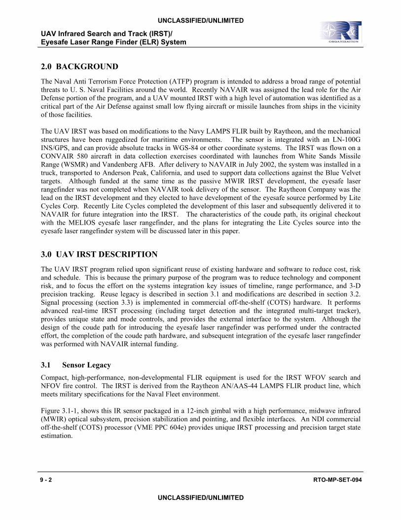
Figure 3.1-1 UAV with ELRF and LN 100G
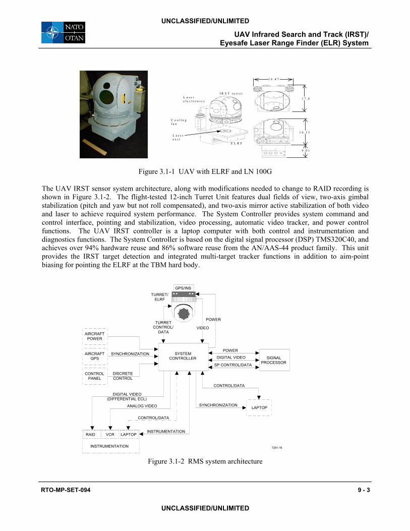
The UAV IRST sensor system architecture, along with modifications needed to change to RAID recording is shown in Figure 3.1-2. The flight-tested 12-inch Turret Unit features dual fields of view, two-axis gimbal stabilization (pitch and yaw but not roll compensated), and two-axis mirror active stabilization of both video and laser to achieve required system performance. The System Controller provides system command and control interface, pointing and stabilization, video processing, automatic video tracker, and power control functions. The UAV IRST controller is a laptop computer with both control and instrumentation and diagnostics functions. The System Controller is based on the digital signal processor (DSP) TMS320C40, and achieves over 94% hardware reuse and 86% software reuse from the AN/AAS-44 product family. This unit provides the IRST target detection and integrated multi-target tracker functions in addition to aim-point biasing for pointing the ELRF at the TBM hard body.
Figure 3.1-2 RMS system architecture
1 6 . 4 7
1 7 . 6
1 6 . 1 3
9 . 0 1
I R S T t u r r e t
E L R F
L a s e re l e c t r o n i c s
C o o l i n g f a n
L a s e re x i t
SIGNALPROCESSOR
SYSTEMCONTROLLER
POWER
DIGITAL VIDEO
SP CONTROL/DATA
DISCRETE CONTROL
CONTROL PANEL
AIRCRAFT GPS
AIRCRAFT POWER
SYNCHRONIZATION
LAPTOPSYNCHRONIZATION
CONTROL/DATA
INSTRUMENTATION
RAID VCR LAPTOP
DIGITAL VIDEO (DIFFERENTIAL ECL)
ANALOG VIDEO
CONTROL/DATA
INSTRUMENTATION
POWER
VIDEOTURRET
CONTROL/DATA
7291-16
GPS/INSTURRET/
ELRF
UAV Infrared Search and Track (IRST)/ Eyesafe Laser Range Finder (ELR) System
9 - 4 RTO-MP-SET-094
UNCLASSIFIED/UNLIMITED
UNCLASSIFIED/UNLIMITED
The baseline ELRF was a Lite Cycles, Inc. Solid State Raman Laser (SSRL) with a diode-pumped Nd:YLF laser coupled to a solid state Raman crystal of barium nitrate, Ba(NO3)2. An eyesafe MELIOS laser rangefinder was substituted (as described later in this report) to demonstrate the 3-D tracking functionality at short ranges (rangefinder electronics limit MELIOS performance to 10 km).
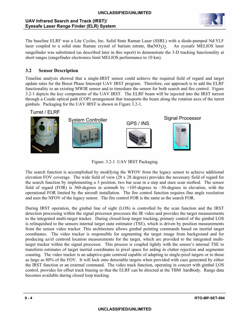
3.2 Sensor Description Timeline analysis showed that a single-IRST sensor could achieve the required field of regard and target update rates for the Boost Phase Intercept UAV IRST program. Therefore, our approach is to add the ELRF functionality to an existing MWIR sensor and to timeshare the sensor for both search and fire control. Figure 3.2-1 depicts the key components of the UAV IRST. The ELRF beam will be injected into the IRST turrent through a Coude optical path (COP) arrangement that transports the beam along the rotation axes of the turret gimbals. Packaging for the UAV IRST is shown in Figure 3.2-1.
Figure. 3.2-1 UAV IRST Packaging
The search function is accomplished by modifying the WFOV from the legacy sensor to achieve additional elevation FOV coverage. The wide field of view (28 x 28 degrees) provides the necessary field of regard for the search function by implementing a 3 position, two bar scan in a step and stare scan method. The sensor field of regard (FOR) is 360-degrees in azimuth by +105-degrees to –50-degrees in elevation, with the operational FOR limited by the aircraft installation. The fire control function requires fine angle resolution and uses the NFOV of the legacy sensor. The fire control FOR is the same as the search FOR. During IRST operation, the gimbal line of sight (LOS) is controlled by the scan function and the IRST detection processing within the signal processor processes the IR video and provides the target measurements to the integrated multi-target tracker. During closed-loop target tracking, primary control of the gimbal LOS is relinquished to the sensors internal target state estimator (TSE), which is driven by position measurements from the sensor video tracker. This architecture allows gimbal pointing commands based on inertial target coordinates. The video tracker is responsible for segmenting the target image from background and for producing az/el centroid location measurements for the target, which are provided to the integrated multi-target tracker within the signal processor. This process is coupled tightly with the sensor’s internal TSE to transform estimates of target inertial coordinates to pixel space for aiding in clutter rejection and segmenter coasting. The video tracker is an adaptive-gate centroid capable of adapting to single-pixel targets or to those as large as 80% of the FOV. It will lock onto detectable targets when provided with cues generated by either the IRST function or an external command. The video track function, operating in concert with gimbal LOS control, provides for offset track biasing so that the ELRF can be directed at the TBM hardbody. Range data becomes available during closed loop tracking.
Turret / ELRFSystem Controller
GPS / INSSignal Processor
UAV Infrared Search and Track (IRST)/ Eyesafe Laser Range Finder (ELR) System
RTO-MP-SET-094 9 - 5
UNCLASSIFIED/UNLIMITED
UNCLASSIFIED/UNLIMITED
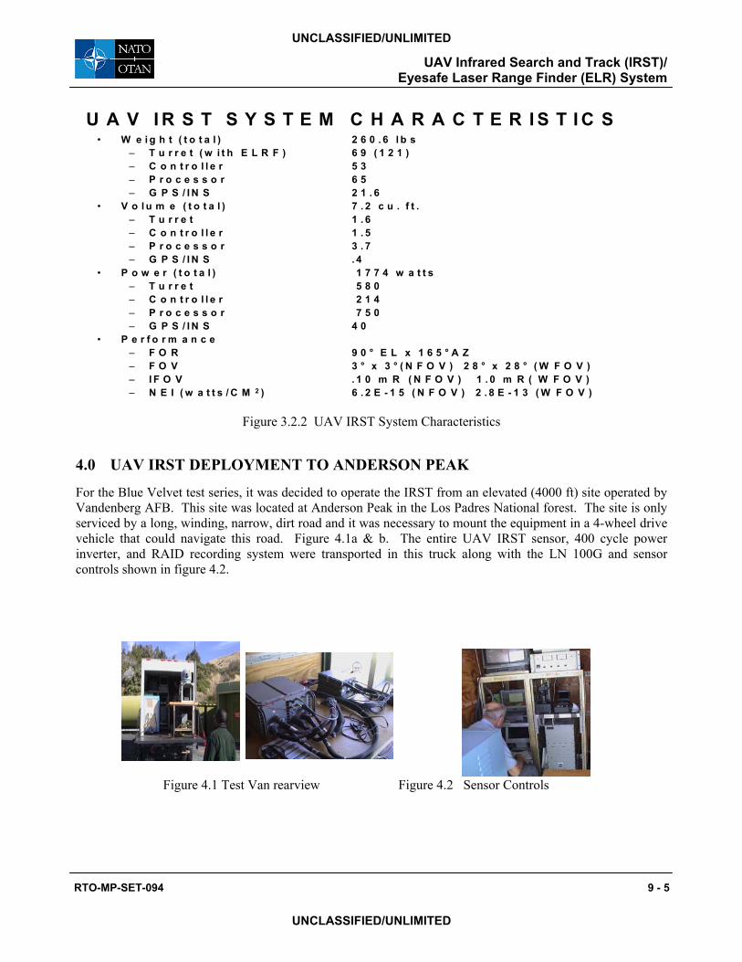
Figure 3.2.2 UAV IRST System Characteristics
4.0 UAV IRST DEPLOYMENT TO ANDERSON PEAK
For the Blue Velvet test series, it was decided to operate the IRST from an elevated (4000 ft) site operated by Vandenberg AFB. This site was located at Anderson Peak in the Los Padres National forest. The site is only serviced by a long, winding, narrow, dirt road and it was necessary to mount the equipment in a 4-wheel drive vehicle that could navigate this road. Figure 4.1a & b. The entire UAV IRST sensor, 400 cycle power inverter, and RAID recording system were transported in this truck along with the LN 100G and sensor controls shown in figure 4.2.
Figure 4.1 Test Van rearview Figure 4.2 Sensor Controls
U A V I R S T S Y S T E M C H A R A C T E R I S T I C S• W e i g h t ( t o t a l ) 2 6 0 . 6 l b s
– T u r r e t ( w i t h E L R F ) 6 9 ( 1 2 1 )– C o n t r o l l e r 5 3– P r o c e s s o r 6 5– G P S / I N S 2 1 . 6
• V o l u m e ( t o t a l ) 7 . 2 c u . f t .– T u r r e t 1 . 6– C o n t r o l l e r 1 . 5– P r o c e s s o r 3 . 7– G P S / I N S . 4
• P o w e r ( t o t a l ) 1 7 7 4 w a t t s– T u r r e t 5 8 0– C o n t r o l l e r 2 1 4– P r o c e s s o r 7 5 0– G P S / I N S 4 0
• P e r f o r m a n c e– F O R 9 0 ° E L x 1 6 5 ° A Z– F O V 3 ° x 3 ° ( N F O V ) 2 8 ° x 2 8 ° ( W F O V )– I F O V . 1 0 m R ( N F O V ) 1 . 0 m R ( W F O V )– N E I ( w a t t s / C M 2 ) 6 . 2 E - 1 5 ( N F O V ) 2 . 8 E - 1 3 ( W F O V )
UAV Infrared Search and Track (IRST)/ Eyesafe Laser Range Finder (ELR) System
9 - 6 RTO-MP-SET-094
UNCLASSIFIED/UNLIMITED
UNCLASSIFIED/UNLIMITED
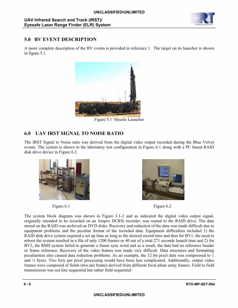
5.0 BV EVENT DESCRIPTION
A more complete description of the BV events is provided in reference 1. The target on its launcher is shown in figure.5.1.
Figure 5.1 Missile Launcher
6.0 UAV IRST SIGNAL TO NOISE RATIO
The IRST Signal to Noise ratio was derived from the digital video output recorded during the Blue Velvet events. The system is shown in the laboratory test configuration in Figure 6.1 along with a PC based RAID disk drive device in Figure 6.2.
Figure 6.1 Figure 6.2
The system block diagram was shown in Figure 3.1-2 and as indicated the digital video output signal, originally intended to be recorded on an Ampex DCRSi recorder, was routed to the RAID drive. The data stored on the RAID was archived on DVD disks. Recovery and reduction of the data was made difficult due to equipment problems and the peculiar format of the recorded data. Equipment difficulties included 1) the RAID disk drive system required a set up time as long as the desired record time and thus for BV1, the need to reboot the system resulted in a file of only 1200 frames or 40 out of a total 271 seconds launch time and 2) for BV2, the RMS system failed to generate a frame sync word and as a result, the data had no reference header or frame reference. Recovery of the video frames was made very difficult. Data structures and formatting peculiarities also caused data reduction problems. As an example, the 12 bit pixel data was compressed to 1 and ½ bytes. Two byte per pixel processing would have been less complicated. Additionally, output video frames were composed of fields (two per frame) derived from different focal plane array frames. Field to field transmission was not line sequential but rather field sequential.
UAV Infrared Search and Track (IRST)/ Eyesafe Laser Range Finder (ELR) System
RTO-MP-SET-094 9 - 7
UNCLASSIFIED/UNLIMITED
UNCLASSIFIED/UNLIMITED
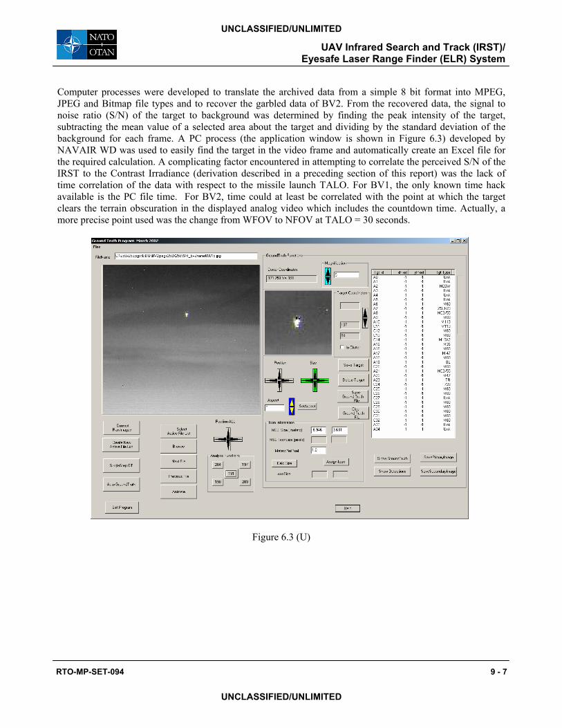
Computer processes were developed to translate the archived data from a simple 8 bit format into MPEG, JPEG and Bitmap file types and to recover the garbled data of BV2. From the recovered data, the signal to noise ratio (S/N) of the target to background was determined by finding the peak intensity of the target, subtracting the mean value of a selected area about the target and dividing by the standard deviation of the background for each frame. A PC process (the application window is shown in Figure 6.3) developed by NAVAIR WD was used to easily find the target in the video frame and automatically create an Excel file for the required calculation. A complicating factor encountered in attempting to correlate the perceived S/N of the IRST to the Contrast Irradiance (derivation described in a preceding section of this report) was the lack of time correlation of the data with respect to the missile launch TALO. For BV1, the only known time hack available is the PC file time. For BV2, time could at least be correlated with the point at which the target clears the terrain obscuration in the displayed analog video which includes the countdown time. Actually, a more precise point used was the change from WFOV to NFOV at TALO = 30 seconds.
Figure 6.3 (U)
UAV Infrared Search and Track (IRST)/ Eyesafe Laser Range Finder (ELR) System
9 - 8 RTO-MP-SET-094
UNCLASSIFIED/UNLIMITED
UNCLASSIFIED/UNLIMITED
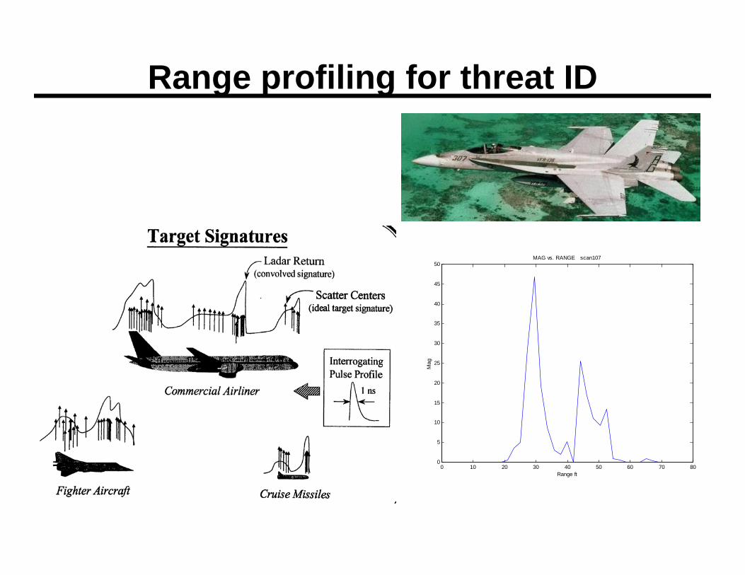
7.0 1-D RANGE PROFILING AS AN AUTOMATIC TARGET RECOGNITION TECHNIQUE
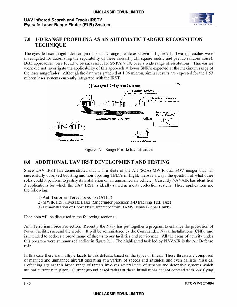
The eyesafe laser rangefinder can produce a 1-D range profile as shown in figure 7.1. Two approaches were investigated for automating the separability of these aircraft ( Chi square metric and pseudo random noise). Both approaches were found to be successful for SNR’s > 10, over a wide range of resolutions. This earlier work did not investigate the applicability of this approach at lower SNR’s expected at the maximum range of the laser rangefinder. Although the data was gathered at 1.06 micron, similar results are expected for the 1.53 micron laser systems currently integrated with the IRST.
Figure. 7.1 Range Profile Identification
8.0 ADDITIONAL UAV IRST DEVELOPMENT AND TESTING Since UAV IRST has demonstrated that it is a State of the Art (SOA) MWIR dual FOV imager that has successfully observed boosting and non-boosting TBM’s in flight, there is always the question of what other roles could it perform to justify its installation on an unmanned air vehicle. Currently NAVAIR has identified 3 applications for which the UAV IRST is ideally suited as a data collection system. These applications are the following:
1) Anti Terrorism Force Protection (ATFP) 2) MWIR IRST/Eyesafe Laser Rangefinder precision 3-D tracking T&E asset 3) Demonstration of Boost Phase Intercept from BAMS (Navy Global Hawk)
Each area will be discussed in the following sections: Anti Terrorism Force Protection: Recently the Navy has put together a program to enhance the protection of Naval Facilities around the world. It will be administered by the Commander, Naval Installations (CNI). and is intended to address a broad range of threats to our facilities and servicemen. All the areas of activity under this program were summarized earlier in figure 2.1. The highlighted task led by NAVAIR is the Air Defense role. In this case there are multiple facets to this defense based on the types of threat. These threats are composed of manned and unmanned aircraft operating at a variety of speeds and altitudes, and even ballistic missiles. Defending against this broad range of threats involves several tiers of sensors and defensive systems which are not currently in place. Current ground based radars at these installations cannot contend with low flying
UAV Infrared Search and Track (IRST)/ Eyesafe Laser Range Finder (ELR) System
RTO-MP-SET-094 9 - 9
UNCLASSIFIED/UNLIMITED
UNCLASSIFIED/UNLIMITED
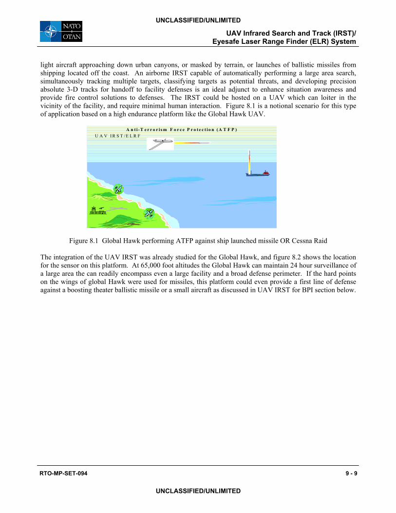
light aircraft approaching down urban canyons, or masked by terrain, or launches of ballistic missiles from shipping located off the coast. An airborne IRST capable of automatically performing a large area search, simultaneously tracking multiple targets, classifying targets as potential threats, and developing precision absolute 3-D tracks for handoff to facility defenses is an ideal adjunct to enhance situation awareness and provide fire control solutions to defenses. The IRST could be hosted on a UAV which can loiter in the vicinity of the facility, and require minimal human interaction. Figure 8.1 is a notional scenario for this type of application based on a high endurance platform like the Global Hawk UAV.
A n t i - T e r r o r is m F o r c e P r o t e c t io n ( A T F P )U A V I R S T /E L R F
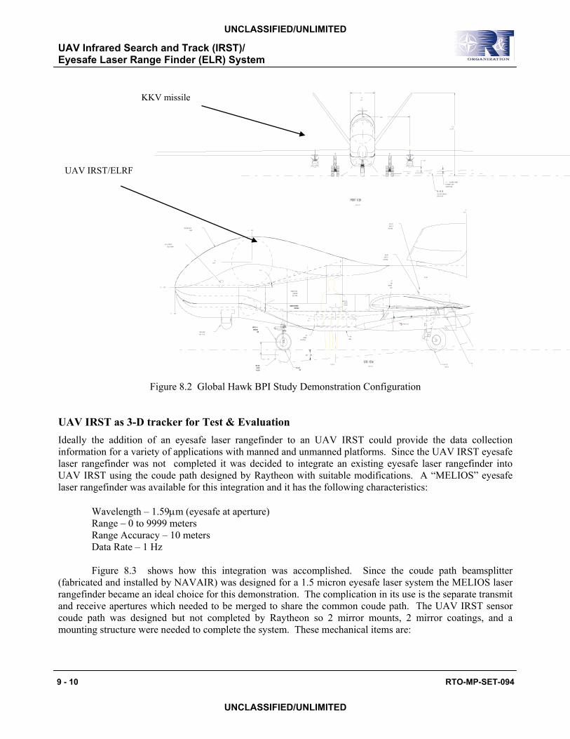
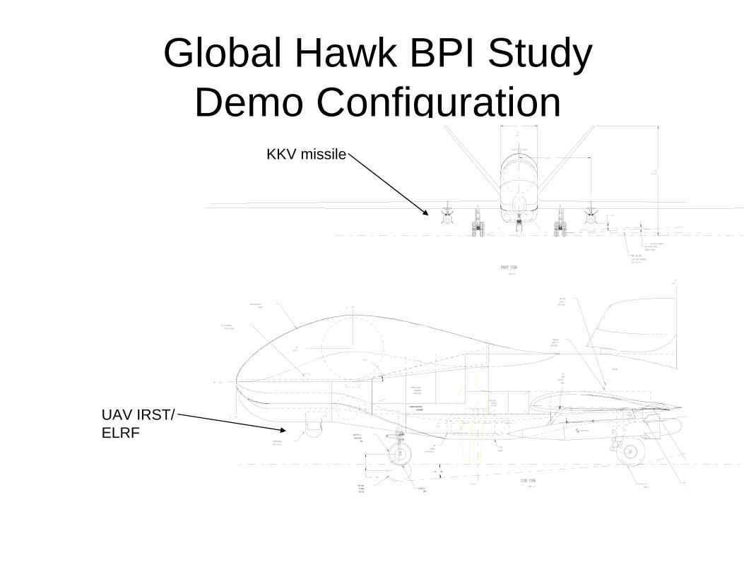
Figure 8.1 Global Hawk performing ATFP against ship launched missile OR Cessna Raid The integration of the UAV IRST was already studied for the Global Hawk, and figure 8.2 shows the location for the sensor on this platform. At 65,000 foot altitudes the Global Hawk can maintain 24 hour surveillance of a large area the can readily encompass even a large facility and a broad defense perimeter. If the hard points on the wings of global Hawk were used for missiles, this platform could even provide a first line of defense against a boosting theater ballistic missile or a small aircraft as discussed in UAV IRST for BPI section below.
UAV Infrared Search and Track (IRST)/ Eyesafe Laser Range Finder (ELR) System
9 - 10 RTO-MP-SET-094
UNCLASSIFIED/UNLIMITED
UNCLASSIFIED/UNLIMITED
Figure 8.2 Global Hawk BPI Study Demonstration Configuration
UAV IRST as 3-D tracker for Test & Evaluation Ideally the addition of an eyesafe laser rangefinder to an UAV IRST could provide the data collection information for a variety of applications with manned and unmanned platforms. Since the UAV IRST eyesafe laser rangefinder was not completed it was decided to integrate an existing eyesafe laser rangefinder into UAV IRST using the coude path designed by Raytheon with suitable modifications. A “MELIOS” eyesafe laser rangefinder was available for this integration and it has the following characteristics: Wavelength – 1.59µm (eyesafe at aperture) Range – 0 to 9999 meters Range Accuracy – 10 meters Data Rate – 1 Hz Figure 8.3 shows how this integration was accomplished. Since the coude path beamsplitter (fabricated and installed by NAVAIR) was designed for a 1.5 micron eyesafe laser system the MELIOS laser rangefinder became an ideal choice for this demonstration. The complication in its use is the separate transmit and receive apertures which needed to be merged to share the common coude path. The UAV IRST sensor coude path was designed but not completed by Raytheon so 2 mirror mounts, 2 mirror coatings, and a mounting structure were needed to complete the system. These mechanical items are:
1.5░WING
INCIDENCEANGLE
57.0
170.1(14.2 FT)
110.80
3.0 MIN GROUND CLEARANCEPER AIRCRAFT STORESINTERFACE MANUAL
4.2░ REF
13.0 REF
12.00
15.0░
4.2░ REF
WL
SCALE 1/10
SCALE 1/20
MODIFIED F-5HIKING NOSE
GEAR
NOSE GEARIN HIKEDPOSITION
FORWARD PAYLOADCOMPARTMENT
ACCESS DOORS
FORWARD PRESSURIZEDCOMPARTMENT
FUEL BAY
ZERO FUELWEIGHT CG
(GEAR DOWN)
TAKE-OFFWEIGHT CG
(GEAR DOWN)
BL0.00
FRONT VIEW
SIDE VIEW
FS440.0
22.0x5.75-12 TIRES (4)18.0x6.5-8
TIRE
RA(T
FORWARD PAYLOADCOMPARTMENT
ACCESS DOORS
TURRET/SENSORMASS = 96 LBS
WL 40.58SHOCK STRUT COMPRESSEDWITH FLAT TIRE
MASS=315 LBS
FS 100.0
FS 190.0
100.0
MODIFIED F-5HIKING NOSE
GEAR
NOSE GEARIN HIKEDPOSITION
FORWARD PRESSURIZEDCOMPARTMENT
WIDE BAND SATCOMRADOME
WL126.00
SARANTENNA
(NO ROTATION)
FS 287.50
18.0x6.5-8TIRE
WL67.0
SAR
RADOME
UHF LOS TRANSMIT/RECEIVE ANTENNA
UAV IRST/ELRF
KKV missile
UAV Infrared Search and Track (IRST)/ Eyesafe Laser Range Finder (ELR) System
RTO-MP-SET-094 9 - 11
UNCLASSIFIED/UNLIMITED
UNCLASSIFIED/UNLIMITED
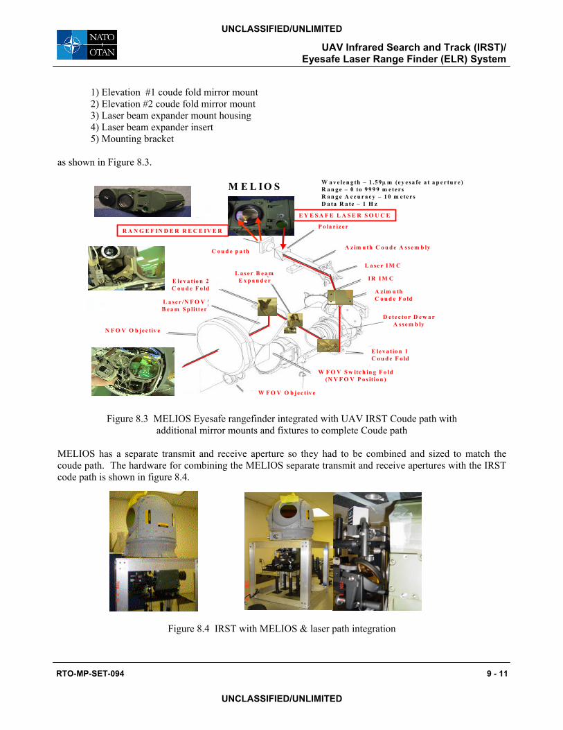
1) Elevation #1 coude fold mirror mount 2) Elevation #2 coude fold mirror mount 3) Laser beam expander mount housing 4) Laser beam expander insert 5) Mounting bracket
as shown in Figure 8.3.
Figure 8.3 MELIOS Eyesafe rangefinder integrated with UAV IRST Coude path with
additional mirror mounts and fixtures to complete Coude path
MELIOS has a separate transmit and receive aperture so they had to be combined and sized to match the coude path. The hardware for combining the MELIOS separate transmit and receive apertures with the IRST code path is shown in figure 8.4.
Figure 8.4 IRST with MELIOS & laser path integration
C o u d e p a th
P o la r iz e r
A z im u th C o u d e A sse m b ly
L a se r IM C
IR IM C
A zim u thC o u d e F o ld
E le v a tio n 1C o u d e F o ld
W F O V S w itc h in g F o ld(N V F O V P o s itio n )
W F O V O b jec tiv e
N F O V O b jec tiv e
L a se r /N F O VB ea m S p litter
E lev a tio n 2C o u d e F o ld
L a ser B e a mE x p a n d e r
D e te c to r D e w a rA sse m b ly
R A N G E F IN D E R R E C E IV E R
E Y E S A F E L A S E R S O U C E
M E L IO S W a v e le n g th – 1 .5 9µm (e y esa fe a t a p e r tu r e )R a n g e – 0 to 9 9 9 9 m e te rsR a n g e A cc u r a c y – 1 0 m e te r sD a ta R a te – 1 H z
M E L IO S
UAV Infrared Search and Track (IRST)/ Eyesafe Laser Range Finder (ELR) System
9 - 12 RTO-MP-SET-094
UNCLASSIFIED/UNLIMITED
UNCLASSIFIED/UNLIMITED
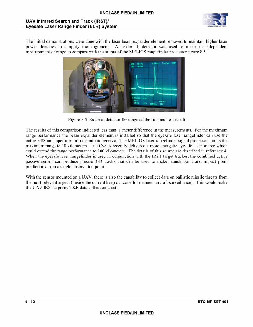
The initial demonstrations were done with the laser beam expander element removed to maintain higher laser power densities to simplify the alignment. An external; detector was used to make an independent measurement of range to compare with the output of the MELIOS rangefinder processor figure 8.5.
Figure 8.5 External detector for range calibration and test result
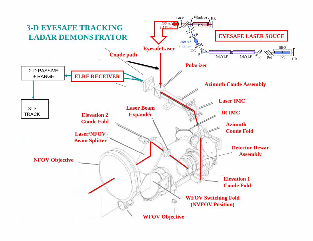
The results of this comparison indicated less than 1 meter difference in the measurements. For the maximum range performance the beam expander element is installed so that the eyesafe laser rangefinder can use the entire 3.88 inch aperture for transmit and receive. The MELIOS laser rangefinder signal processor limits the maximum range to 10 kilometers. Lite Cycles recently delivered a more energetic eyesafe laser source which could extend the range performance to 100 kilometers. The details of this source are described in reference 4. When the eyesafe laser rangefinder is used in conjunction with the IRST target tracker, the combined active passive sensor can produce precise 3-D tracks that can be used to make launch point and impact point predictions from a single observation point. With the sensor mounted on a UAV, there is also the capability to collect data on ballistic missile threats from the most relevant aspect ( inside the current keep out zone for manned aircraft surveillance). This would make the UAV IRST a prime T&E data collection asset.
UAV Infrared Search and Track (IRST)/ Eyesafe Laser Range Finder (ELR) System
RTO-MP-SET-094 9 - 13
UNCLASSIFIED/UNLIMITED
UNCLASSIFIED/UNLIMITED
9.0 CONCLUSION
The UAV IRST has successfully been used to support two data collections against the most widely deployed boosting theater ballistic missile. The performance model has been shown to have good agreement with the sensed data from the BV trials. The coude path has been completed and the eyesafe laser rangefinding has been demonstrated using the MELIOS unit A higher power eyesafe laser source has been delivered, and when integrated with the IRST could support performance out to 100 kilometers. The combination of the precise angular track and the laser range information allow the system to produce target state estimations that allow prediction of the future positions of targets. In addition the eyesafe laser rangefinding can also be used to support automatic air target recognition based on 1-D range profiles, as demonstrated on the F/A-18 and MIG-23 database.
10.0 REFERENCES
1. Robert T. Hintz, "UAV IRST for Ballistic Missile Defense, Proc. 2003 Meeting of the Mss Defense Senosors, Environments and Algoithms II (18-20 November 2003). 2. Raytheon Systems Corporation Advanced Airborne Electro-Optics (ABEO), “Final Report for the IRST/ELRF Risk Mitigation Sensor (RMS), (28 February 2001). 3. Robert T. Hintz, “UAV IRST for Ballistic Missile Defense, Proc. 2004 Meeting of the 2004 National Fire Control Symposium (9-12 August 2004).
UAV Infrared Search and Track (IRST)/ Eyesafe Laser Range Finder (ELR) System
9 - 14 RTO-MP-SET-094
UNCLASSIFIED/UNLIMITED
UNCLASSIFIED/UNLIMITED
GLOBAL HAWKIRST
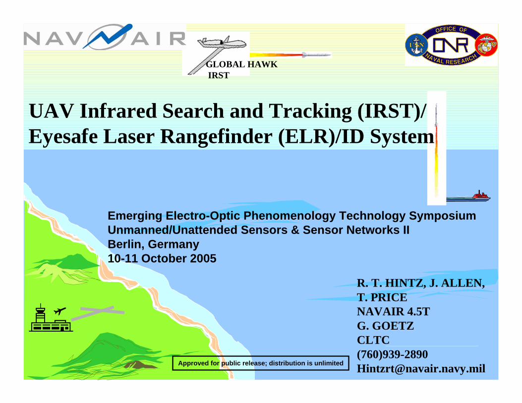
R. T. HINTZ, J. ALLEN, T. PRICENAVAIR 4.5TG. GOETZ CLTC(760)[email protected]
UAV Infrared Search and Tracking (IRST)/Eyesafe Laser Rangefinder (ELR)/ID System
Emerging Electro-Optic Phenomenology Technology SymposiumUnmanned/Unattended Sensors & Sensor Networks IIBerlin, Germany10-11 October 2005
Approved for public release; distribution is unlimited
IRST FOR UAVs
• Air Defense Application– Anti-Terrorism Force Protection (ATFP)– Naval Facilities around the world
• System Description– Hardware – Signal Processing & Software
• Data Collections– Airborne– Blue Velvet– MANPAD
• Recent Activities– Blue Velvet data analysis– Eyesafe Laser Rangefinder Integration & Testing– 1-D Profiling for Threat ID
OUTLINE
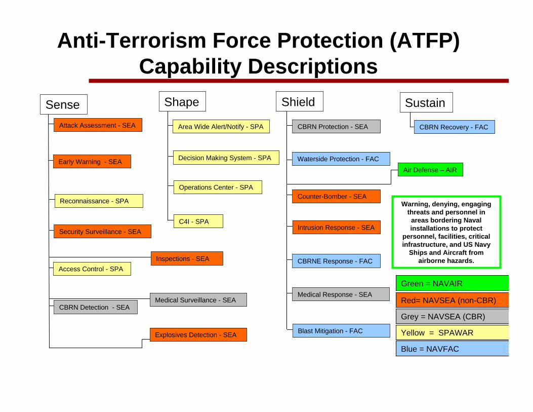
Shape
Area Wide Alert/Notify - SPA
Decision Making System - SPA
Operations Center - SPA
C4I - SPA
SenseAttack Assessment - SEA
Early Warning - SEA
Reconnaissance - SPA
Security Surveillance - SEA
Access Control - SPA
CBRN Detection - SEA
Inspections - SEA
Medical Surveillance - SEA
Explosives Detection - SEA
Shield
CBRN Protection - SEA
Waterside Protection - FAC
Counter-Bomber - SEA
Intrusion Response - SEA
CBRNE Response - FAC
Medical Response - SEA
Sustain
CBRN Recovery - FAC
Anti-Terrorism Force Protection (ATFP) Capability Descriptions
Blast Mitigation - FAC
Red= NAVSEA (non-CBR)
Grey = NAVSEA (CBR)
Yellow = SPAWAR
Blue = NAVFAC
Green = NAVAIR
Air Defense – AIR
Warning, denying, engaging threats and personnel in
areas bordering Naval installations to protect
personnel, facilities, critical infrastructure, and US Navy
Ships and Aircraft from airborne hazards.
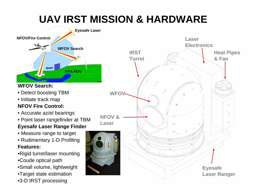
UAV IRST MISSION & HARDWARE
WFOV Search:• Detect boosting TBM• Initiate track mapNFOV Fire Control:• Accurate az/el bearings• Point laser rangefinder at TBMEyesafe Laser Range Finder• Measure range to target• Rudimentary 1-D ProfilingFeatures:•Rigid turret/laser mounting•Coude optical path •Small volume, lightweight•Target state estimation•3-D IRST processing
Eyesafe Laser
FPA FOV
7291-12
WFOV Search
NFOV/Fire Control
EyesafeLaser Ranger
LaserElectronics
Heat Pipes& Fan
IRSTTurret
WFOV
NFOV &Laser
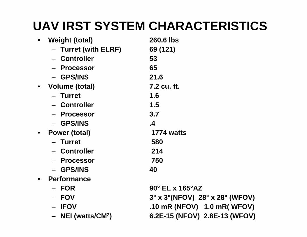
UAV IRST SYSTEM CHARACTERISTICS• Weight (total) 260.6 lbs
– Turret (with ELRF) 69 (121)– Controller 53– Processor 65– GPS/INS 21.6
• Volume (total) 7.2 cu. ft.– Turret 1.6– Controller 1.5– Processor 3.7– GPS/INS .4
• Power (total) 1774 watts– Turret 580– Controller 214– Processor 750– GPS/INS 40
• Performance– FOR 90° EL x 165°AZ– FOV 3° x 3°(NFOV) 28° x 28° (WFOV)– IFOV .10 mR (NFOV) 1.0 mR( WFOV)– NEI (watts/CM2) 6.2E-15 (NFOV) 2.8E-13 (WFOV)
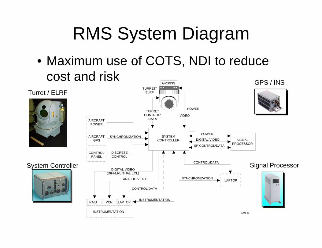
RMS System Diagram• Maximum use of COTS, NDI to reduce
cost and risk
SIGNALPROCESSOR
SYSTEMCONTROLLER
POWER
DIGITAL VIDEO
SP CONTROL/DATA
DISCRETECONTROL
CONTROLPANEL
AIRCRAFTGPS
AIRCRAFTPOWER
SYNCHRONIZATION
LAPTOPSYNCHRONIZATION
CONTROL/DATA
INSTRUMENTATION
RAID VCR LAPTOP
DIGITAL VIDEO(DIFFERENTIAL ECL)
ANALOG VIDEO
CONTROL/DATA
INSTRUMENTATION
POWER VIDEO
TURRETCONTROL/
DATA
7291-16
GPS/INSTURRET/
ELRFTurret / ELRF
System Controller
GPS / INS
Signal Processor
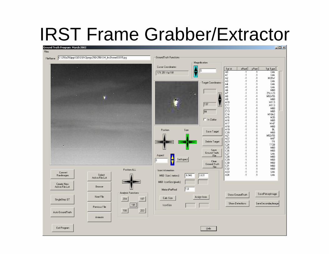
IRST Frame Grabber/Extractor
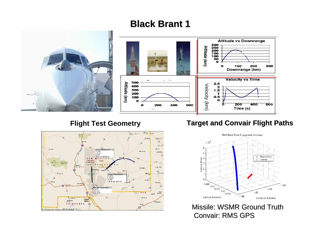
Flight Test Geometry Target and Target and ConvairConvair Flight PathsFlight Paths
Black Brant 1Black Brant 1
Missile: WSMR Ground TruthMissile: WSMR Ground TruthConvairConvair: RMS GPS: RMS GPS
Velocity (km)
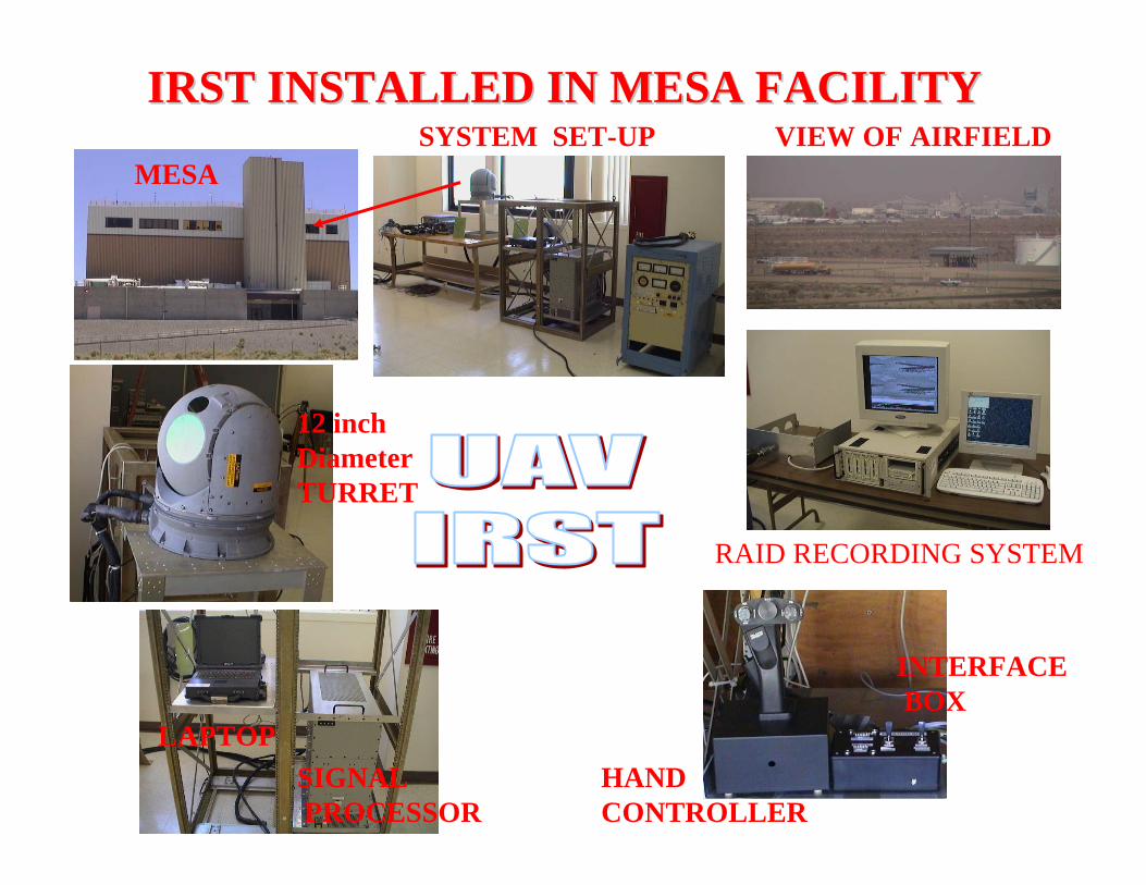
IRST INSTALLED IN MESA FACILITYIRST INSTALLED IN MESA FACILITYSYSTEM SET-UP
LAPTOPSIGNALPROCESSOR
MESAVIEW OF AIRFIELD
RAID RECORDING SYSTEM
12 inchDiameterTURRET
INTERFACEBOX
HANDCONTROLLER
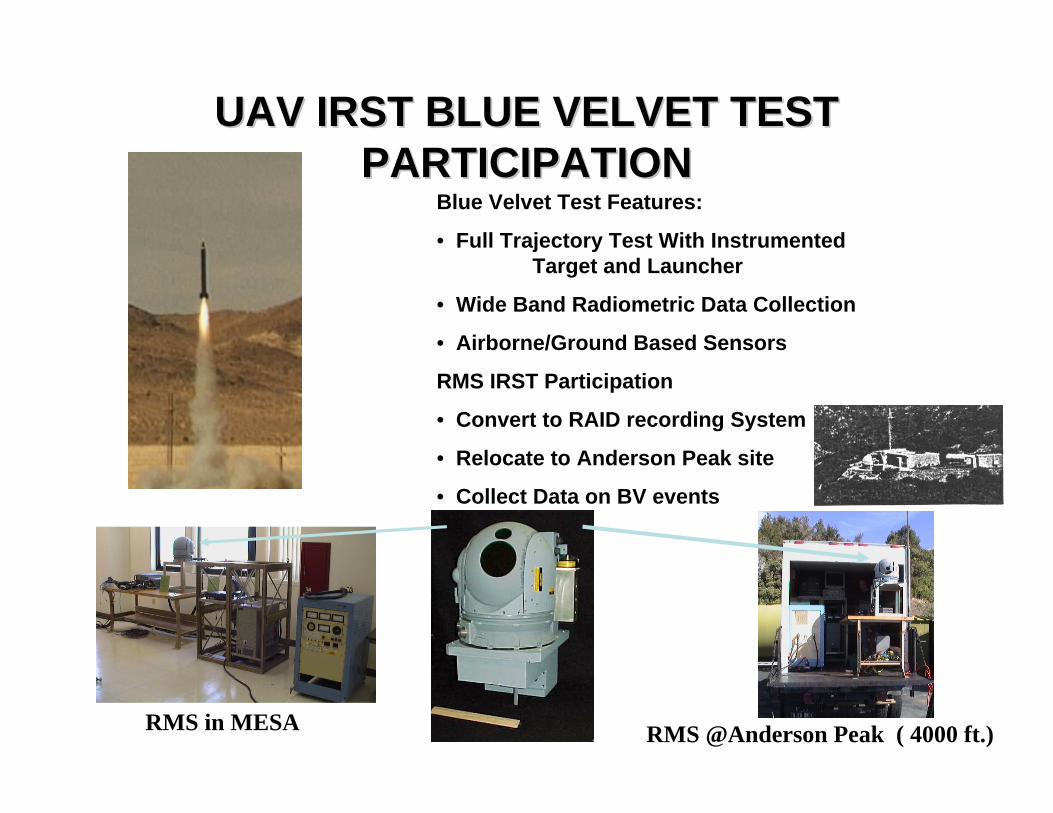
UAV IRST BLUE VELVET TEST UAV IRST BLUE VELVET TEST PARTICIPATIONPARTICIPATION
Blue Velvet Test Features:
• Full Trajectory Test With Instrumented Target and Launcher
• Wide Band Radiometric Data Collection
• Airborne/Ground Based Sensors
RMS IRST Participation
• Convert to RAID recording System
• Relocate to Anderson Peak site
• Collect Data on BV events
RMS @Anderson Peak ( 4000 ft.)RMS in MESA
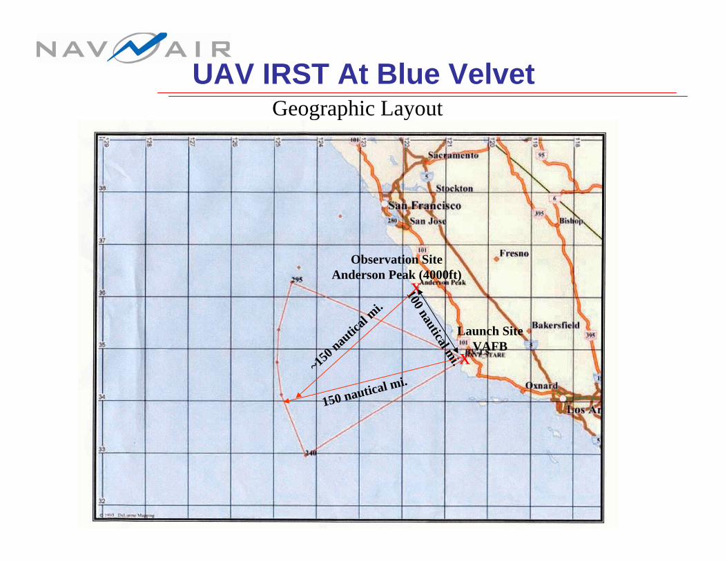
UAV IRST At Blue VelvetGeographic Layout
Observation SiteAnderson Peak (4000ft)
x
Launch SiteVAFBx
100 nautical mi.
150 nautical mi.~15
0 nau
tical
mi.
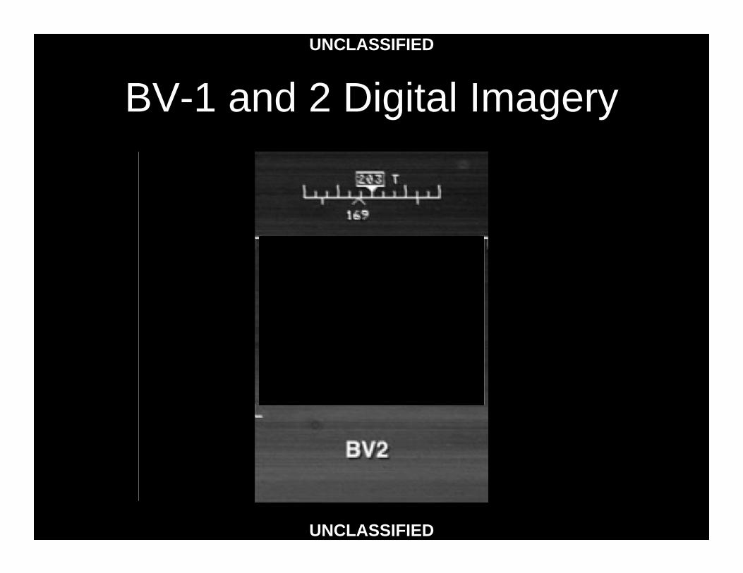
BV-1 and 2 Digital ImageryUNCLASSIFIED
UNCLASSIFIED
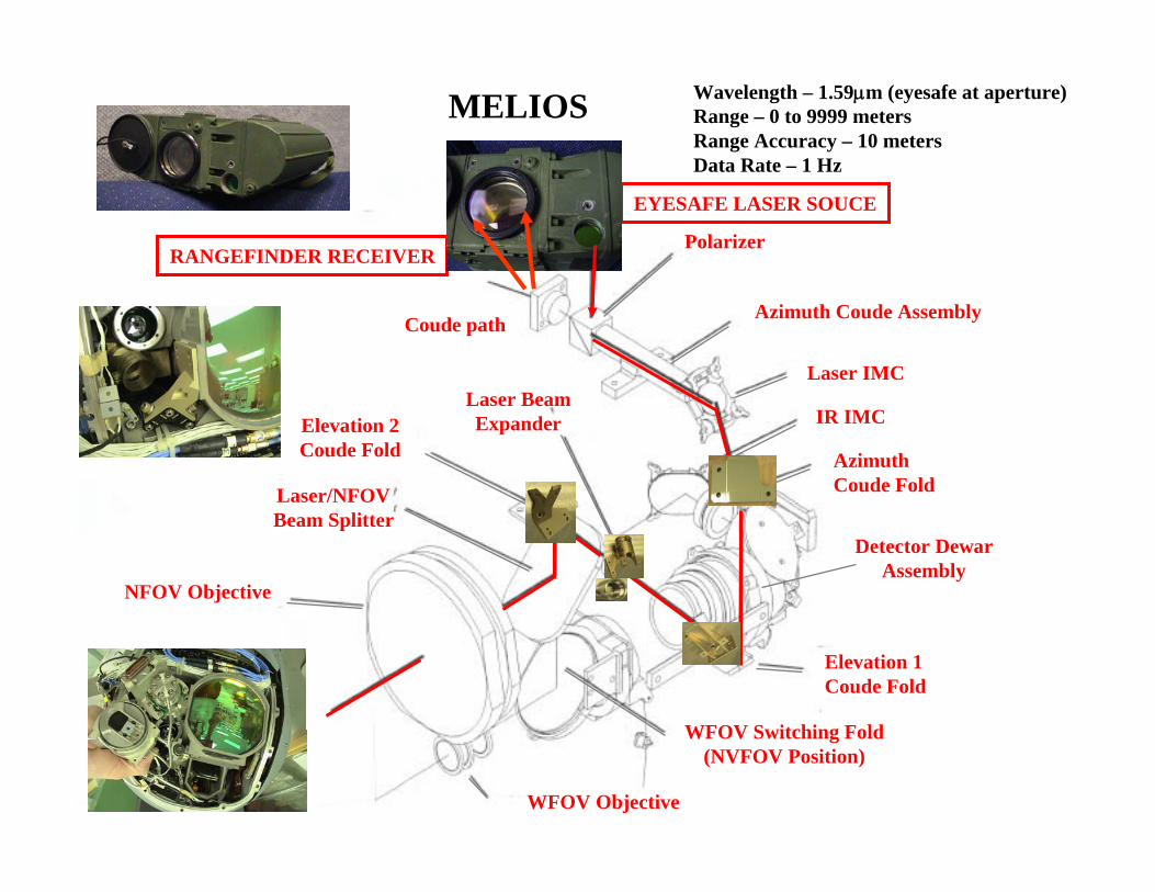
Coude path
Polarizer
Azimuth Coude Assembly
Laser IMC
IR IMC
AzimuthCoude Fold
Elevation 1Coude Fold
WFOV Switching Fold(NVFOV Position)
WFOV Objective
NFOV Objective
Laser/NFOVBeam Splitter
Elevation 2Coude Fold
Laser BeamExpander
Detector DewarAssembly
RANGEFINDER RECEIVER
EYESAFE LASER SOUCE
MELIOS Wavelength – 1.59μm (eyesafe at aperture)Range – 0 to 9999 metersRange Accuracy – 10 metersData Rate – 1 Hz
MELIOS
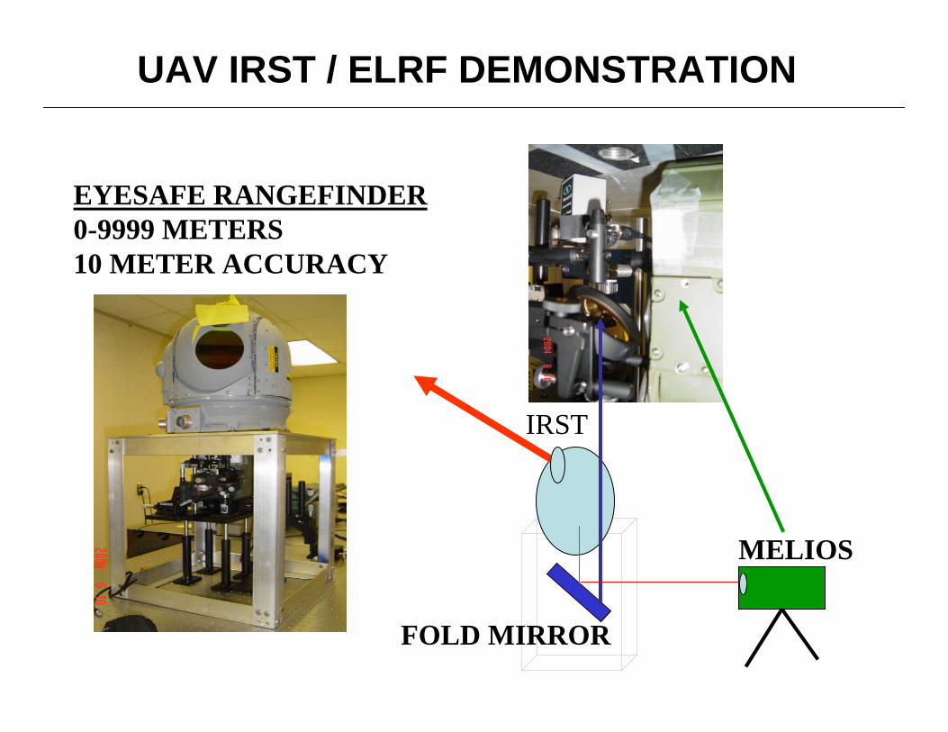
UAV IRST / ELRF DEMONSTRATION
EYESAFE RANGEFINDER0-9999 METERS10 METER ACCURACY
MELIOS
IRST
FOLD MIRROR
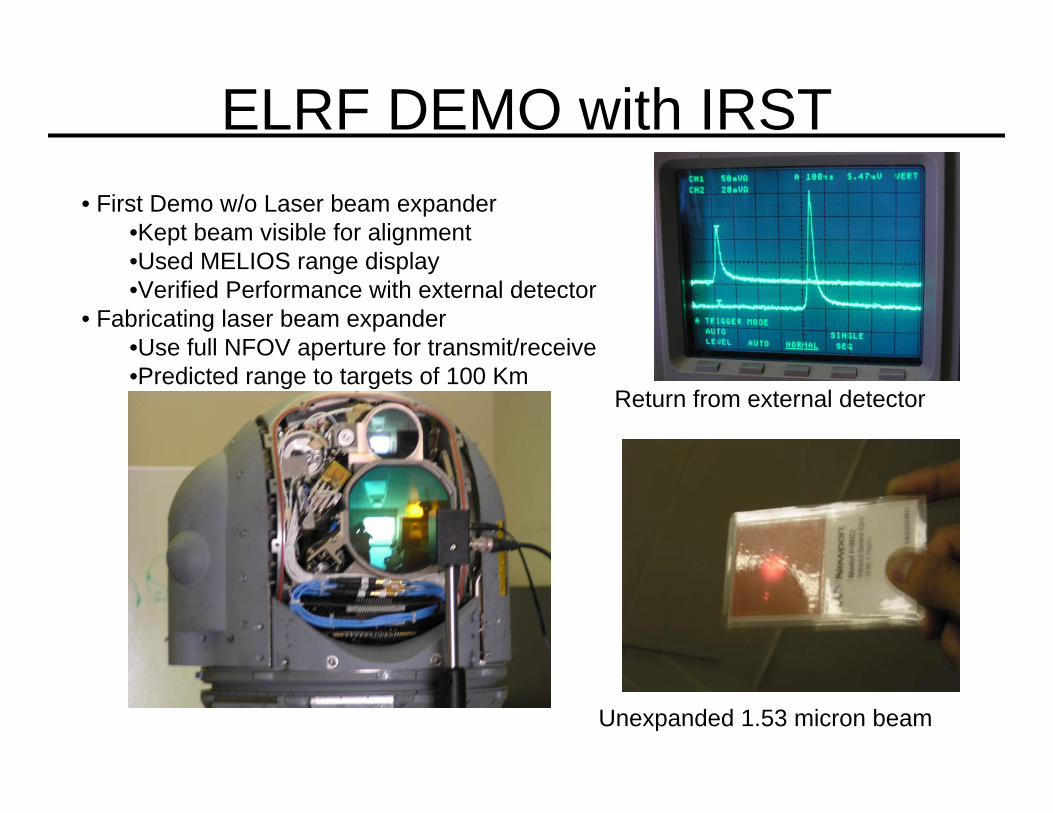
ELRF DEMO with IRST• First Demo w/o Laser beam expander
•Kept beam visible for alignment•Used MELIOS range display•Verified Performance with external detector
• Fabricating laser beam expander•Use full NFOV aperture for transmit/receive•Predicted range to targets of 100 Km
Return from external detector
Unexpanded 1.53 micron beam
Coude path
Polarizer
Azimuth Coude Assembly
Laser IMC
IR IMC
AzimuthCoude Fold
Elevation 1Coude Fold
WFOV Switching Fold(NVFOV Position)
WFOV Objective
NFOV Objective
Laser/NFOVBeam Splitter
Elevation 2Coude Fold
Laser BeamExpander
3-D EYESAFE TRACKINGLADAR DEMONSTRATOR
EyesafeLaser
Detector DewarAssembly
ELRF RECEIVER2-D PASSIVE
+ RANGE
3-D TRACK
150 mJ1.533 μm
GRM
BN
Windows HR
300 mJ1.321 μm
POC
Nd:YLFNd:YLF R Pol PC
BBO
HR
EYESAFE LASER SOUCE
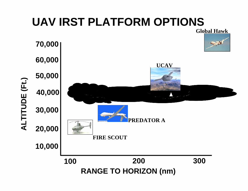
UAV IRST PLATFORM OPTIONS
50,000
40,000
30,000
20,000
10,000
ALT
ITU
DE
(Ft.)
RANGE TO HORIZON (nm)100 200 300
60,000
70,000
FIRE SCOUT
PREDATOR A
UCAV
Global Hawk
Global Hawk BPI StudyDemo Configuration
1.5░
WING
INCIDENCE
ANGLE
57.0
170.1
(14.2 FT)
110.80
3.0 MIN GROUND CLEARANCE
PER AIRCRAFT STORES
INTERFACE MANUAL
4.2░ REF
13.0 REF
12.00
15.0░
4.2░ REF
WL
SCALE 1/10
SCALE 1/20
MODIFIED F-5
HIKING NOSE
GEAR
NOSE GEAR
IN HIKED
POSITION
FORWARD PAYLOAD
COMPARTMENT
ACCESS DOORS
FORWARD PRESSURIZED
COMPARTMENT
FUEL BAY
ZERO FUEL
WEIGHT CG
(GEAR DOWN)
TAKE-OFF
WEIGHT CG
(GEAR DOWN)
BL
0.00
FRONT VIEW
SIDE VIEW
FS
440.0
22.0x5.75-12
TIRES (4)18.0x6.5-8
TIRE
RA
(T
FORWARD PAYLOAD
COMPARTMENT
ACCESS DOORS
TURRET/SENSOR
MASS = 96 LBS
WL 40.58SHOCK STRUT COMPRESSED
WITH FLAT TIRE
MASS=315 LBS
FS 100.0
FS 190.0
100.0
MODIFIED F-5
HIKING NOSE
GEAR
NOSE GEAR
IN HIKED
POSITION
FORWARD PRESSURIZED
COMPARTMENT
WIDE BAND SATCOM
RADOME
WL
126.00
SAR
ANTENNA
(NO ROTATION)
FS 287.50
18.0x6.5-8
TIRE
WL
67.0
SAR
RADOME
UHF LOS TRANSMIT/
RECEIVE ANTENNA
UAV IRST/ELRF
KKV missile
Range profiling for threat ID
0 10 20 30 40 50 60 70 800
5
10
15
20
25
30
35
40
45
50MAG vs. RANGE scan107
Range ft
Mag
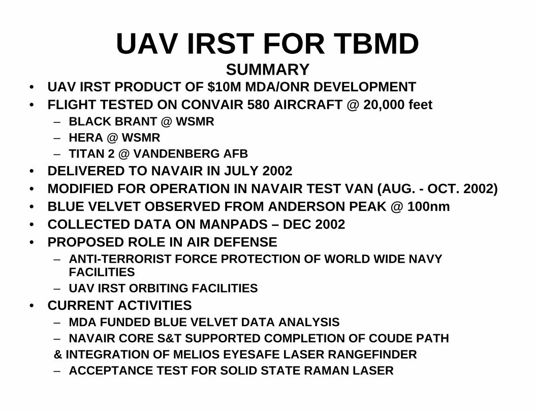
UAV IRST FOR TBMD• UAV IRST PRODUCT OF $10M MDA/ONR DEVELOPMENT• FLIGHT TESTED ON CONVAIR 580 AIRCRAFT @ 20,000 feet
– BLACK BRANT @ WSMR – HERA @ WSMR– TITAN 2 @ VANDENBERG AFB
• DELIVERED TO NAVAIR IN JULY 2002 • MODIFIED FOR OPERATION IN NAVAIR TEST VAN (AUG. - OCT. 2002)• BLUE VELVET OBSERVED FROM ANDERSON PEAK @ 100nm• COLLECTED DATA ON MANPADS – DEC 2002• PROPOSED ROLE IN AIR DEFENSE
– ANTI-TERRORIST FORCE PROTECTION OF WORLD WIDE NAVY FACILITIES
– UAV IRST ORBITING FACILITIES• CURRENT ACTIVITIES
– MDA FUNDED BLUE VELVET DATA ANALYSIS– NAVAIR CORE S&T SUPPORTED COMPLETION OF COUDE PATH& INTEGRATION OF MELIOS EYESAFE LASER RANGEFINDER– ACCEPTANCE TEST FOR SOLID STATE RAMAN LASER
SUMMARY