the software for structural analysis of tall …exmact.excon.cz/downloads/exmact_manual.pdf · the...
TRANSCRIPT

THE SOFTWARE FOR STRUCTURAL ANALYSIS OF TALL SLENDER STRUCTURES
Monopoles, chimneys and lattice towers
USER’S MANUAL
April 2017

2
USER’S MANUAL
Content
1 Introduction ..................................................................................................................................... 4
2 Analysis capabilities ......................................................................................................................... 4
2.1 Model of the structure ............................................................................................................ 4
2.2 Analysis .................................................................................................................................... 4
3 Responsibility .................................................................................................................................. 5
4 Contact ............................................................................................................................................ 5
5 Copyrights ........................................................................................................................................ 5
6 Installation ....................................................................................................................................... 6
6.1 Installation ............................................................................................................................... 6
6.2 Hardware and software requirements .................................................................................... 6
7 Manual ............................................................................................................................................. 6
7.1 Generally ................................................................................................................................. 6
7.2 Project, Standards ................................................................................................................... 9
7.3 Structure ................................................................................................................................ 10
7.3.1 Type of the structure ..................................................................................................... 10
7.3.2 Geometry ....................................................................................................................... 11
7.3.3 Lattice structure definition ............................................................................................ 11
7.3.4 Lattice cross section characteristics .............................................................................. 13
7.3.5 Tube structure definition............................................................................................... 14
7.3.6 Cross section characteristics for monopoles and chimneys.......................................... 15
7.3.7 Discrete structure components ..................................................................................... 16
7.3.8 Materials and profiles .................................................................................................... 16
7.3.9 Bolts ............................................................................................................................... 17
7.3.10 Connections for lattice structures ................................................................................. 18
7.3.11 Connections for monopoles .......................................................................................... 22
7.3.12 Flange connections according to Petersen.................................................................... 25

3
USER’S MANUAL
7.3.13 Important points of chimneys and monopoles ............................................................. 31
7.4 Foundation ............................................................................................................................ 32
7.5 Ancillaries .............................................................................................................................. 33
7.6 Calculation model .................................................................................................................. 34
7.7 Loading .................................................................................................................................. 35
7.7.1 Load combinations ........................................................................................................ 35
7.7.2 Snow load ...................................................................................................................... 37
7.7.3 Ice load .......................................................................................................................... 38
7.7.4 Wind load ...................................................................................................................... 42
7.8 Analysis .................................................................................................................................. 52
7.8.1 Shaft computation data ................................................................................................. 52
7.8.2 Second order effects ..................................................................................................... 53
7.8.3 Analysis method ............................................................................................................ 54
7.9 Results ................................................................................................................................... 60
7.9.1 Natural frequencies and mode shapes .......................................................................... 60
7.9.2 Response of the tower .................................................................................................. 62
7.9.3 Assessment – lattice towers .......................................................................................... 64
7.9.4 Assessment – monopoles and chimneys ....................................................................... 71
7.9.5 Foundation .................................................................................................................... 78
8 Report ............................................................................................................................................ 80
9 Acknowledgement ......................................................................................................................... 80
10 Literature ................................................................................................................................... 80
10.1 General .................................................................................................................................. 80
10.2 National annexes of eurocode .............................................................................................. 81
10.2.1 Czech Republic ............................................................................................................... 81
10.2.2 Germany ........................................................................................................................ 82

4
USER’S MANUAL
1 Introduction
Software EXMACT has been developed for analysis of tall slender structures as towers and chimneys,
especially in accordance with European standards. The software allows advanced calculation
methods such as the spectral analysis. The determination of wind drag, icing and snow load is
included. The generation of project report can be carried out.
2 Analysis capabilities
2.1 Model of the structure
The finite element method is used for the mathematical model of the structure. Plane beam model is used for the monopoles and chimneys, three-dimensional bar model for the lattice towers.
The typical structural systems of lattice towers are prepared for generation of the model, see chapter 7.3.3. Other systems are not supported in this version of the software.
As some structural systems are not theoretically stable using the bar model (nodes supported only in one plane are unstable out of this plane), the “dumb elements” are used as notional bracing. Resultant axial forces in the dumb elements must be zero or close to zero. Otherwise the model cannot be assumed reliable!
The load is applied in the nodes of the structure. Local bending effect due to connection of ancillaries between the nodes is not included to the assessment of members of the structure. The effect depends on the way of ancillary connection. The local bending effect is usually minor, but in case of significant ancillaries connected between nodes of lattice structure, appropriate bars must be additionally checked separately!
2.2 Analysis
The dynamic characteristics of the structure (natural frequencies and mode shapes) are determined by the modal analysis.
The response of the structure due to applied loads is determined using static or dynamic analysis according to the selected method.
The following method can be chosen for the wind response evaluation:
Monopoles and chimneys (or towers modelled as vertical beam)
o Quasi-static analysis according to EN 1991-1-4 [4]
o Equivalent static analysis according to EN 1993-3-1 [8]
o Simplified spectral analysis
o Spectral analysis
o Quasi-static analysis according to ČSN 730035 [13]
o Analysis according to ČSN 730035 [13] using mode shapes decomposition
o Quasi-static analysis according to DIN 4131 [17]

5
USER’S MANUAL
Lattice towers
o Quasi-static analysis according to EN 1991-1-4 [4]
o Equivalent static analysis according to EN 1993-3-1 [8]
o Simplified spectral analysis
o Quasi-static analysis according to ČSN 730035 [13]
o Analysis according to ČSN 730035 [13] using mode shapes decomposition
o Quasi-static analysis according to DIN 4131 [17]
The second order effect can be determined by non-linear static calculation in the software (for monopoles and chimneys in this version only).
3 Responsibility
The software is developed to assist designers in structural analysis of towers and chimneys. User
must have an understanding of these structures, good knowledge of the standards and experience
with designing and assessment of these structures.
The software has been carefully tested. However, please know that EXCON, a.s. makes no guarantees
concerning interpretation of the outputs, accuracy of results or errors as well as damages resulting
from the use of this manual and the software.
4 Contact
EXCON, a.s.
Sokolovská 187/203
190 00 Prague 9
Czech Republic
Software web page: http://exmact.excon.cz/
E-mail: [email protected], [email protected]
5 Copyrights
EXCON, a.s. All rights are reserved.

6
USER’S MANUAL
6 Installation
6.1 Installation
No installation is needed. The files are copied to created folder in user’s computer. Run
“EXMACT.exe” to open program. The desktop shortcut may be created to run “EXMACT.exe”.
6.2 Hardware and software requirements
Hardware requirements: RAM ≥ 2GB
Disk space ≥ 50 MB
Software requirements: MS Windows (32 bit or 64 bit)
.NET 4.0
MS Office Word
7 Manual
7.1 Generally
The Graphical User Interface (GUI) is used to enter input data. The main window of GUI is divided into three main sections: Toolbar, Tree and Panel of input and output data, see Fig. 1.
Toolbar provides direct access to the basic function. It is placed at the top of the main window. Toolbar contain 7 items:
New ... Create a new project
Open ... Open an existing project
Save ... Save a current project
Save as ... Save a current project as another
Close ... Close a current project
Word ... Create a report of current project
About ... Show product version number and other information
Note: More projects can be opened at the same time.

7
USER’S MANUAL
Fig. 1 Graphical user interface
Toolbar
Tree Panel of input and output data

8
USER’S MANUAL
Tree provides direct access to all functions. It is placed at the left side of the main window.
Tree is different for poles and lattice towers, see Fig. 2.
Fig. 2 Tree window for monopoles and chimneys (left), tree window for lattice towers (right)
The items of the tree and the corresponding panels of input/output data are described in the following chapters.
Colours of boxes
Three colours are used for boxes in the software: white, yellow and gray.
White boxes are to be filled or can be changed by user. If predefine value in white box is changed, colour of box changes to yellow. If there is need to change back value in yellow box to Exmact proposed value, delete number in box and press “Enter” or press “CTRL and 0” and then “Enter”.

9
USER’S MANUAL
ATTENTION: Yellow - manually changed - boxes remain unchanged, when initial parameters are modified.
Example: If different projected areas are set for different wind directions then boxes on page “Wind drag”, which differ from page “Ancillaries” change colour to yellow. When afterwards parameters on page “Ancillaries” are modified, all white boxes are automatically modified, while yellow boxes remain unchanged.
Gray boxes serve for information and cannot be modified.
7.2 Project, Standards
Project identification information can be assigned to the project. The selection of standards is done
on this page, see Fig. 3. (General European standards, the Czech National Annex, the German
National Annex, the German DIN standards and the old Czech standards ČSN are included in this
version)
Fig. 3 Page “Project, Standards”
Note: If system of European standards is chosen for analysis and assessment of the structure, the following
standards are used: EN 1990 [1], EN 1991-1-1 [2], EN 1991-1-3 [3], EN 1991-1-4 [4], EN 1993-1-1 [5],
EN 1993-1-6 [6], EN 1993-1-8 [7], EN 1993-3-1 [8], EN 1993-3-2 [9], EN 1997-1 [10], EN 1090-2 [11].
Standard ISO 12494 [12] is used for icing on structure.
If system of German DIN standards is chosen for analysis and assessment of the structure, the
following standards are used: DIN 4131 [17], DIN 18800-1 [19], DIN 18800-2 [20], DIN 18800-4 [21],
DIN 1054 [22]. Standard DIN 1055-5 [18] or ISO 12494 [12] are used for icing on structure.

10
USER’S MANUAL
7.3 Structure
The geometry of the structure, cross section and other characteristics of the structure are defined in
this section. The section comprises following pages.
7.3.1 Type of the structure
Page contains 2 main selections, see Fig. 4:
The type of the structure ... “Tower” or
“Guyed mast” (guyed mast is not included in this version)
The type of the tower ... “Tube (or another beam)” for monopoles or chimneys or
“Triangular lattice tower” or
“Square lattice tower”
For lattice structures 3D model is used. 2D model is used for monopoles or chimneys.
Fig. 4 Page “Type of the Structure”

11
USER’S MANUAL
7.3.2 Geometry
User defines the heights of panels of the structure and their division. The panel name can be
assigned to each panel. Only white boxes are filled. Grey boxes are for the user’s information only,
see Fig. 5. Unlimited number of panels can be defined.
Fig. 5 Page “Geometry”
7.3.3 Lattice structure definition
The width of lattice tower are determined on this page, see Fig. 6. The width of the structure can be
set only in the heights, where the slope of the legs changes. These manually filled boxes will be
marked (yellow box), other widths are calculated automatically for a constant slope of the legs
between yellow boxes.
The division of the panel to elements is subsequently determined. If “Division type” is chosen as
“Height”, the height of panel is divided equally to element heights. If “Division type” is chosen as
“Angle”, the heights of elements are calculated with respect of constant slope of the diagonals.

12
USER’S MANUAL
Fig. 6 Page “Lattice structure definition”
The panel type determines the lattice structural system. The types, which can be used and their type
numbers are depicted in Fig. 7.
Fig. 7 Panel structural types
Note: Dashed and dotted members in Fig. 7 are optional. If a profile is set on the next page “Lattice
cross section characteristics”, the dashed or dotted member is used in the model. If the box
“profile” on the next page is empty, the member isn’t included in the model – in case of the
dotted items. In case of the dashed items, the member is included in the model as a “dumb”
element.

13
USER’S MANUAL
The secondary bracing members (secondary diagonals and horizontals) can be assumed in calculation. Because these members bear no primary forces, they are not included in the model. But they can be assumed in the wind drag evaluation and in the tower assessment.
Horizontal bracing members are divided into two groups marked I and II, see Fig. 8.
Fig. 8 Horizontal bracing member I and II
7.3.4 Lattice cross section characteristics
The profiles and materials are assigned to members of lattice towers, see Fig. 9. The software
includes automatic calculation of cross section characteristics for tubes and rods and database of
profiles and basic materials. Other user-defined profiles and materials can be added on the page
“Materials and Profiles”, see chapter 7.3.8. The weight addition can be added to self weight of
members.
Inserting of profiles with automatic calculation and profiles from the database:
• For TUBES write: TUdiameter*thickness example: TU89*3,6
• For RODS write: RDdiameter example: RD70
• For EQUAL-LEG ANGLES write: Lwidth*thickness example: L50*5
• For UNEQUAL-LEG ANGLES write: Lwidth*width2*thickness example: L50*30*5
Horizontal bracing member II
Horizontal bracing member I

14
USER’S MANUAL
Fig. 9 Page “Lattice cross section characteristics”
Note: If user click on small plus in first column, elements of panel will show and plus will change to minus. If user click on minus, elements will hide. When some value for panel is filled, the same value is automatically given to all elements of this panel. When value for element is changed to value different from value for panel, box will be yellow marked.
7.3.5 Tube structure definition
The width (diameter) of the structure, thickness of wall and material are defined on page “Tube
structure definition”, see Fig. 10. Width at top and bottom point is defined for tapered panels. One
width is entered for straight panels. If a slope of tapered part of the structure is constant through
more panels, set only top width and bottom width of this part. Widths in intermediate points are
calculated automatically. Different widths beneath and above single node can be set. In this case,
first enter top width of panel under the node and then setting of bottom width of upper panel will be
allowed.

15
USER’S MANUAL
Fig. 10 Page “Tube structure definition”
7.3.6 Cross section characteristics for monopoles and chimneys
Cross section characteristics and weight additions are defined on page “Cross section
characteristics”, see Fig. 11. For tubes the automatic calculation of cross section characteristics is
included. User can input also other profiles. In this case cross section characteristics must be filled
manually. Other user-defined materials can be added on the page “Materials and Profiles”, see
chapter 7.3.8.
Fig. 11 Page “Cross section characteristics” for monopoles and chimney

16
USER’S MANUAL
7.3.7 Discrete structure components
The discrete structure components (platforms etc.) are defined on this page, see Fig. 12. The height
of attachment, the weight, the projected area and the force coefficient are filled for each discrete
component. The height of attachment is arbitrary and may not be equal to the height of the nodes of
the structure, but it cannot be higher than total height of the structure.
Note: If the height of attachment is equal to height of some node in the structure, user can click on
the box in column “height” and choose node of structure in shown offer, see Fig. 13. This procedure
works for heights of ancillaries defined in chapter 7.5 too.
Fig. 12 Page “Discrete structure components”
Fig. 13 Page “Discrete structure components” – offer of structure nodes is shown
7.3.8 Materials and profiles
Database of basic offered materials and summary of used profiles can be seen on page “Materials and Profiles”. User can add new material or profile.
The modulus of elasticity and yield strength are set in the material definition. The type of fabrication is added to the material definition, see upper section in Fig. 14.
The cross section area, the diameter or the width, the radiuses of gyration and buckling curves are set in the profile definition, see lower section in Fig. 14.
Note: For monopoles and chimneys page includes only upper part “Used materials”.

17
USER’S MANUAL
Fig. 14 Page “Materials and Profiles”
7.3.9 Bolts
Database of bolts and bolt classes can be seen on page “Bolts”. User can add new bolt or bolt class.
The dimensions and cross section areas are set in the bolt definition, see upper part in Fig. 15.
In the lower part of page is bolt class definition. The yield strength, ultimate strength, factor αv , shear resistance reduction factor for bolts M12 and M14 in 2 mm clearance holes and modulus of elasticity (only for DIN standards) have to be set.

18
USER’S MANUAL
Fig. 15 Page “Bolts”
7.3.10 Connections for lattice structures
Connections of elements are defined on the page “Connections”. The main used types of connections
are chosen for detail design. There are “Bolted flanged connection” and “Angle legs connection” for
legs connections and “Angles connected by one leg” and “Connection of tube” for joints of other
elements.
Resistance of representative types of connections according to EN 1993-1-8 [7] or DIN 18 800 [19] is
given automatically after determination qualities of connection (such as profile and material of
elements, number and type of bolts, dimensions and spacing etc.). Needed inputs are divided in
logical groups, see Fig. 16. Calculation works only if connection meets design rules, so the minimum
spacing is pre-filled for used bolts. On the right, user can see particular resistances of single events,
which impacts on total resistance of connection.
Defined connections are matched with single members on page “Assessment”, see chapter 7.9.3.
Note: Rows of bolts are assumed parallel to axial force in member, according to [7].

19
USER’S MANUAL
Fig. 16 Page “Connections”
In case of need another type of connection (connections calculated by hand or in special software for
connections), user can choose “Other connection” and set only its resistance.
The bolted flange connection is used for connection of tube legs. The diameter of bolt should not be
smaller than 12mm and all bolts should be pre-loaded due to fatigue. If user leaves boxes in input of
flange 2 empty, it is supposed that flange 2 is identical to flange 1. Positive influence of possible
reinforcement plates is not included in calculation. Dimensions of connection are described in Fig.
17.
Type of connections
Inputs Partial resistances

20
USER’S MANUAL
Fig. 17 Bolted flange connection
Angle legs connection is available for equal-leg angles. It is supposed that spacing and bolts are
selfsame on both sides of one angle and all bolts are in normal holes. User can choose orthogonal or
staggered spacing (can be different in each angle), maximum 2 rows of bolts in one leg of angle are
allowed. Dimensions of connection are described in Fig. 18.
Fig. 18 Angle legs connection

21
USER’S MANUAL
Angles connected by one leg are used for connection of equal-leg angle to joint plate or another
angle. Maximum 2 rows of bolts are allowed, spacing for 2 rows is staggered. Dimensions of
connection are described in Fig. 19.
Fig. 19 Angle connected by one leg
Inputs of connection of tube are the same for three main used arrangements (see Fig. 20) of
connection of tube to joint plate. Maximum 2 rows of bolts are allowed, spacing for 2 rows is
orthogonal. For fillet weld resistance check simplified method is used. Resistance of weld is
independent of the orientation of the weld throat plane to the applied force. Total weld length is
sum of lengths of one-sided fillet welds. If user leave boxes in part “Tube tearing resistance” empty,
it is supposed, that plate 1 tearing from tube can’t happen, so this partial resistance is not included in
total resistance of connection.
Fig. 20 Connection of tube

22
USER’S MANUAL
7.3.11 Connections for monopoles
Bolted flanged connections according to Fig. 21 and Fig. 22 can be defined in the software. Three
types of tabs are prepared for monopole connections:
o “Flange connection of tubes” – for connection by two bolted flanges
o “Base flange of tube” – for base flange laying on anchor bolts (when bolts bears both tension
and compression forces, adjusting nuts are present and concrete support is neglected)
o “Other connections” – for connections, the resistances were calculated outside the software
Exmact
Both “Flange connection of tubes” and “Base flange of tube” can be set with or without stiffeners.
Fig. 21 Connection of monopole – bolts outside the tube – plan (left), detail of connection of two panels (middle), detail of base flange (right)

23
USER’S MANUAL
Fig. 22 Connection of monopole – bolts inside the tube - plan (left), detail of connection of two panels (middle), detail of base flange (right)
RECOMMENDATIONS:
o Assume plastic hinge appears in the tube wall above the flange (or above stiffeners, if
present), if the tube is of cross section class 4
Set “Assume yielding in tube above flange/stiffeners” to option “yes” in this case.
o Do not “count with tube” if two tubes with significantly different diameter are connected.
Set “Count with tube” to option “no” in this case.
If this option is chosen, the compression forces are borne only by stiffeners. It is supposed,
the tube is not sufficiently supported and transfer of compression forces through the tube is
neglected (diagram in Fig. 23 does not contain magenta tube component).
Resistance determination
First, maximum possible force in single bolt is determined. It is minimum value of tension resistance
of bolt, punching shear resistance and bending resistance of flange or wall of the tube with the
inclusion of prying forces. Program considers following lengths of patterns:
Connection without stiffeners: 2πm, πm + p, 2p, 4m + 1,25e, 0,5p + 2m + 0,625e, p
where p is used for flange and/or wall of tube, if required
Connection with stiffeners: 2πm, 4m + 1,25e, 2αm-(4m + 1,25e), p
where p is used for wall of tube above stiffeners, if required

24
USER’S MANUAL
Symbols correspond to EN 1993-1-8 [7].
Fig. 23 Scheme of connection – substitute tubes and stress diagram
Calculation for “Flange connection of tube”
Afterwards, the position of neutral axis is found by iteration calculation using elastic-plastic
behaviour. Bolts acts in tension, tube and stiffeners in compression only. Groups of individual
components (i.e. bolts and stiffeners) are substituted for single notional collective tubes with
equivalent characteristics, see Fig. 23. Centerline of bolt substitute tube passes through centres of
bolts. Centerline of stiffener substitute tube passes through middle of width hs, see Fig. 21 and Fig.
22.
Maximum tension in substitute tube of bolts, marks as σb,max, is equivalent to maximum possible
force in bolt. Maximum compression in tube is equivalent to yield strength of tube material.
Maximum compression in substitute tube of stiffeners isstt
yts tt
ft
,max, +
⋅=σ , where tt,s is thickness of
substitute tube of stiffeners and tt is wall thickness of tube. It is assumed, the stress in tube above
stiffeners reach the yield stress. Then, stiffeners take part of forces, but overall force in stiffeners and
tube cannot be greater than force corresponding to yield stress in tube above stiffeners.

25
USER’S MANUAL
Calculation for “Base flange of tube”
Only substitute tube of bolts is considered (tension and compression) using elastic behaviour.
Maximum stress is equivalent to maximum possible force in bolt.
Comment:
Results of above described calculation were widely compared to full analysis of connections in
software IDEA Connection using FEM models. Results have been found safe and conservative. Above
mentioned recommendations resulted from this comparison study.
ATTENTION:
Some partial resistances are not included in the calculation. They have to be checked by user.
o Welds
o Resistance of stiffeners
o Shear resistance of connection
o Fatigue*
o Tube wall failure under stiffeners (caused by horizontal or vertical forces from stiffeners), if a
stiffening ring under stiffeners is not present and/or if “yielding in tube above stiffeners” is
not assumed**.
Note *): Especially fatigue of anchor bolts, which acts in tension even compression, might be crucial.
Note **): This failure was not crucial for compared examples, if above mentioned recommendations
were applied. The attention has to be paid especially when upper and lower tube diameter differs
significantly. In this case, it is recommended to use a ring under stiffeners or carry out full analysis of
connection.
Because the substitute tubes are used, the calculation is not reliable for small number of bolts
(approx. less than 12).
Bending resistances are checked in “Assessment / Connection check” only. Influence of axial
(compression) force is neglected.
7.3.12 Flange connections according to Petersen
Flange connections can be calculated according to Petersen [23] when DIN 4131 standard is used.
Calculation of following resistances is included in the software:
o Tension resistances of tube‘s and rod’s flanges for the lattice towers
o Bending resistance of flanges of monopoles
o Resistance of the base connection - for the base flange laying on anchor bolts (when bolts
bears both tension and compression forces, adjusting nuts are present and concrete
support is neglected)

26
USER’S MANUAL
Elastic as well as plastic method can be chosen for determination of resistance of flange connection
between steel tubes and rods in tension or bending. Elastic method is available for the base flange
connection.
Flange connection between tubes and rods
Tension and bending resistances of flanges are calculated according to chapters 9.7.4.2 - 9.7.4.4 and
23.2.9 [23]. Symbols correspond to Petersen [23] or following figures (Fig. 24, Fig. 25). Symbols and
schemes are the same for flanges in tension (for lattice structures) and bending (for monopoles).
Fig. 24 Scheme of outside (left) and inside (right) flange of tube

27
USER’S MANUAL
Fig. 25 Scheme of flange of rod
Lengths of bending lines of the flange c0 and c1 are set in accordance with Fig. 26. Both lengths can be
adjusted by user.
Fig. 26 Scheme of lengths c0 and c1 for outside (left) and inside (right) flange
The exception is for determination of following parameters:
o Rotational stiffness Kw
o Stress caused by tension in tube wall σw (sigma_w)
o Tension resistance of tube wall NRd,PL,3,(I)
These parameters are calculated for the length c0* depicted in Fig. 27.

28
USER’S MANUAL
Fig. 27 Scheme of the length c0*
The different flange types can be assumed for the lattice structures:
o ”Open”
o ”Full”
o ”Full, no rotation”
The flanges of monopoles are assumed to be open only.
Open flange is depicted in Fig. 28. Flange is intended for tube. A rotational stiffness K in intersection of flange and tube’s wall is calculated according to equation
sr
scEKK W ⋅
⋅⋅==5,8
3
Fig. 28 Scheme of “Open” flange

29
USER’S MANUAL
Full flange is depicted in Fig. 29. Flange is intended for tube or rod. A rotational stiffness K in intersection of flange and tube’s wall or rod’s weld is determined as
flW KKK += for tubes or
flKK = for rods,
where D
IEK fl
fl
⋅⋅=
2 and Kw is the same as for the open flange.
Fig. 29 Scheme of “Full” flange
Full flange with no rotation in connection with profile is depicted in Fig. 30. Flange is intended for
rods. A rotational stiffness K in intersection of flange and rod’s weld is assumed to be ∞=K .
Fig. 30 Scheme of “Full, no rotation” flange

30
USER’S MANUAL
Base flange connection
Resistance of the base flange is determined in accordance with chapter 23.2.10.2 and 23.2.6 [23].
Symbols correspond to [23] or Fig. 31.
Fig. 31 Scheme of the base flange and the ring
Note: Diameter and wall thickness of tube in ring level DI,ring and tI,ring are calculated from the tube
parameters in bottom section. If the ring is placed in different (higher) section, DI,ring and tI,ring have to
be set by user.
If the ring bears forces from bolts (nuts are above ring) choose “yes” in column “Ring bended by bolt”. Then bending of the ring will be taken into account. Bending of the base flange is taken into account every time (base flange is laying on the adjusting nut under the flange).

31
USER’S MANUAL
Bending moment is determined for simple beam static scheme for maximum force in bolt in the middle of span ast.
Different configuration of base flange and ring can be considered, see Fig. 32.
Fig. 32 Scheme of different configurations of base flange and ring
ATTENTION:
Some partial resistances are not included in the calculation. They have to be checked by user.
o Welds
o Resistance of stiffeners
o Shear resistance of connection
o Fatigue*
Note *): Especially fatigue of anchor bolts, which acts in tension even compression, might be crucial.
7.3.13 Important points of chimneys and monopoles
The resultant internal forces, deflections and check of member of chimneys and monopoles are
shown in the nodes (at the ends of elements). If other points should be examined (e.g. openings in
greater distance from any node), the heights of these points are defined on this page, see Fig. 33.

32
USER’S MANUAL
Fig. 33 Page “Important points”
7.4 Foundation
The foundation of tower is defined on the page “Foundation”, see Fig. 34. Pad has square ground
plan and two steps. The dimensions of pad and embedment depth are set in upper part of page. In
case of need set another shape of upper step, set width of step B2 so that volume of the square step
was identical to volume of another shaped step. In lower part of page the geotechnical
characteristics are defined.
Dimensions of pad for monopoles and for lattices are described in Fig. 35.

33
USER’S MANUAL
Fig. 34 Page “Foundation”
Fig. 35 Dimensions of the pad for monopoles and chimneys (left) and for lattice towers (right)
7.5 Ancillaries
The linear and discrete ancillaries are defined on the page “Ancillaries”, see Fig. 36. The height of
attachment (in case of the linear ancillary bottom and top height), the weight, the projected area,
the force coefficient and angle of wind incidence are defined. The heights are arbitrary and may not
be equal to the height of nodes of the structure, but cannot be higher than total height of the
structure.

34
USER’S MANUAL
Fig. 36 Page “Ancillaries”
Note: Angle of wind incidence is angle between wind direction and longitudinal axis of linear ancillary.
7.6 Calculation model
The basic model of the monopoles or chimneys can be extended on the page depicted in Fig. 37.
Important points and points with ancillaries can be added to the basic point of the model (ends of
elements) and used for creation of mathematical model of the structure.
If an ancillary is placed between nodes and the point, where the ancillary lies, is added to the
calculation model, new node is created and the load of ancillary is applied in this point.
If the point, where the ancillary lies, is not added to the calculation model, the load of ancillary is
applied in both lower and upper nearest nodes of model (divided according to distances from these
nodes). In case of large number of ancillaries in one panel is not usually necessary to divide this panel
to large number of additional element.
The resultant internal forces, deflections and check of member of monopoles and chimneys are
shown only in the nodes of calculation model.
In case of lattice structure, the load is always applied to the nodes of lattice structure, i.e. load is
divided to lower and upper nearest nodes according to distances from these nodes.

35
USER’S MANUAL
Fig. 37 Page “Calculation model”
7.7 Loading
7.7.1 Load combinations
The six basic load combinations according to EN standards are prepared as default, see Fig. 38:
COM 1 ... Wind action on the ice-free structure with unfavourable vertical action
COM 2 ... Wind action on the ice-free structure with favourable vertical action
COM 3 ... Dominant ice and accompanying wind action with unfavourable vertical action
COM 4 ... Dominant ice and accompanying wind action with favourable vertical action
COM 5 ... Dominant wind and accompanying ice action with unfavourable vertical action
COM 6 ... Dominant wind and accompanying ice action with favourable vertical action
The reliability classes are set separately for structure of tower (according to Annex A, EN 1993-3-1
[8]), for foundation – limit state GEO/STR (according to EN 1990 [1]) and for foundation – limit state
EQU (according to EN 1990 [1]). The combination factors for ice ψice and wind ψw are filled
automatically according to selected National Annex (see page “Project, Standard”, chapter 7.2),
alternatively they may be set manually.
Note: For DIN standards only first four combinations are prepared for structure. Load combinations
for foundation are not shown, because characteristic values of loads in anchoring level are given.

36
USER’S MANUAL
The corresponding partial factors of load, combination factors and factor k for the wind pressure
reduction are set according to EN standards and National Annexes.
User can add other user-defined combination and choose which combinations will be calculated (in
the column “Used”).
Note: Reliability class according to Annex A, EN 1993-3-1 [8] and according to EN 1990 [1] has
different definition. If structure is classified as class 2, foundation doesn’t need to be classified
as RC2.
Fig. 38 Page “Load combinations”

37
USER’S MANUAL
7.7.2 Snow load
The uniform snow load per meter height and the discrete snow load can be assumed in the
calculation, see Fig. 39. The characteristic value of snow load (or directly snow load for DIN
standards) is set according to selected standard (see page “Project, Standard”, chapter 7.2) and
selected snow zone. This value and coefficients for snow load can be alternatively set manually by
user.
The discrete snow load applies in points, where discrete structure components and discrete
ancillaries are placed.
Fig. 39 Page “Snow load”

38
USER’S MANUAL
7.7.3 Ice load
Ice load and shape of ice is assumed according to ISO 12494 [12]. The rime or the glaze is assumed
for weights and shapes of ice determination. Choice of ice type is situated on the top of page “Ice
load”, see Fig. 40.
Two ice situations are prepared as default “Ice 1-dominant” and “Ice 2-accompanying”, which
correspond to default definition of load combinations (see page “Load combinations”, chapter 7.7.1),
see middle section in Fig. 40. Other ice situations can be added by user.
The ice is defined separately on the structure, discrete structure components, linear and discrete
ancillaries.
Note: For DIN standards glaze ice according to DIN 1055-5 [18] is set as default. It can be changed to
ice determination according ISO standard [12].
Note: There can be defined both rime and glaze in one project, but calculation can be run only for
Rime ice or only for Glaze ice.
7.7.3.1 Rime ice
The overall ice weight in the panels and rime vane lengths are determined on this page, see Fig. 40,
Fig. 41. The ice weight mk is set according to selected ice class for rime or it can be set manually by
user.
The ice load is evaluated automatically for the lattice structure (Fig. 40) and for tubular poles and
chimneys (Fig. 41). The ice load of discrete structure component, linear and discrete ancillaries must
be set manually by user (for all ice situations and wind directions), see Fig. 42.
In case of lattice tower user must check default rime shape types (according to Fig. 4 in ISO 12494
[12]) (for all required wind directions and the ice situations) and fill slope of secondary diagonals to
horizontal plane (tab “Secondary diagonals), if these members occur.
Note: For tube is default type set as “AB” (i.e. type A or B according to Fig. 4 in ISO 12494 [12]).
For other profile is default type set as “CD” (i.e. type C or D according to Fig. 4 in ISO 12494
[12]), which gives unfavourable values. Default types can be changed by user to obtain more
accurate values.

39
USER’S MANUAL
Fig. 40 Page “Ice load”, tab “Ice weight on lattice structure” for rime ice
Fig. 41 Page “Ice load”, tab “Ice weight on structure” for monopoles and chimneys for rime ice

40
USER’S MANUAL
Fig. 42 Page “Ice load”, tabs: Ice weight on linear ancillaries, discrete ancillaries and discrete structure components for rime ice
7.7.3.2 Glaze ice
The overall ice weight in the panels and glaze width are determined on this page, see Fig. 43, Fig. 44.
The ice thickness t is set according to selected ice class for glaze or it can be set manually by user.
The ice load is evaluated automatically for the lattice structure (Fig. 43) and for tubular poles and
chimneys (Fig. 44). The ice load of discrete structure component, linear and discrete ancillaries must
be set manually by user (for all ice situations and wind directions), see Fig. 45.

41
USER’S MANUAL
Fig. 43 Page “Ice load”, tab “Ice weight on lattice structure” for glaze ice
Fig. 44 Page “Ice load”, tab “Ice weight on structure” for monopoles and chimneys for glaze ice

42
USER’S MANUAL
Fig. 45 Page “Ice load”, tabs: Ice weight on linear ancillaries, discrete ancillaries and discrete structure components for glaze ice
7.7.4 Wind load
7.7.4.1 Basic wind characteristics
Wind zone, basic wind speed (for mean return period of 50 years or different) and terrain category
are defined on the page “Wind”. Settings of wind characteristics according to Czech national annex
[CZE4] are shown on Fig. 46, according to German national annex [DEU2] on Fig. 47.
For DIN standards fundamental wind pressure and altitude are set, see Fig. 48.

43
USER’S MANUAL
Fig. 46 Page “Wind”, settings according to Czech national annex
Fig. 47 Page “Wind”, settings according to German national annex

44
USER’S MANUAL
Fig. 48 Page “Wind”, settings according to DIN 4131 [17]
7.7.4.2 Wind directions and wind drag types
The wind direction assumed in calculation are defined on the page “Wind directions”, see Fig. 49.
Three wind drag types are prepared as default “Wind drag 1” for ice-free structure, “Wind drag 2 +
Ice 1” for dominant ice and accompanying wind and “Wind drag 2 + Ice 2” for dominant wind and
accompanying ice. Other types of wind drag can be alternatively added by user.

45
USER’S MANUAL
Fig. 49 Page “Wind directions”
7.7.4.3 Wind velocity and pressure
The wind velocity and pressure are shown on the page depicted in Fig. 50. The orography factor can
be set there (differently for all wind drag types and wind directions).
For DIN standards application of constant wind pressure for towers up to 50 m can be switched on.
Additional pressure in obedience to DIN 4131 [17] can be set, see Fig. 51.

46
USER’S MANUAL
Fig. 50 Page “Wind speed and pressure” for Eurocode
Fig. 51 Page “Wind speed and pressure” for DIN standard

47
USER’S MANUAL
7.7.4.4 Wind drag
The wind drag of lattice towers is determined according to chapter B.2.1.3, Annex B, EN 1993-3-1 [8]
or according to chapter A.1.3, Annex A, DIN 4131 [17]. The flow regime of iced tubular members of
lattice towers depends on the shape of ice. The default setting for rime is flow regime for flat items,
which is unfavourable. In case of small rime vane length the flow regime can be changed manually to
“subcritical” (or „circular“ for DIN standards with ice acoording to ISO 12494 [12]), see page depicted
in Fig. 52.
Fig. 52 Page “Wind drag”, tabs: Structure-lattice, Flow regime of iced legs
The projected areas of plates in joints or stiffeners can be set on page depicted in Fig. 53.

48
USER’S MANUAL
Fig. 53 Page “Wind drag”, tabs: Structure-lattice, Projected area normal to face
Force coefficient of the structure is calculated automatically on page shown in Fig. 54. The addition
of overall width of the tower (e.g. parts of ancillaries or platforms extended beyond the face of the
structure) is set by user on this page.
Fig. 54 Page “Wind drag”, tabs: Structure-lattice, Wind force coefficient
The projected areas and force coefficients of iced discrete structure components, iced linear and
discrete ancillaries must be set manually by user (for all wind directions and wind drag types), see
Fig. 55.

49
USER’S MANUAL
Fig. 55 Page “Wind drag”, tabs: Wind drag of discrete structure components, linear and discrete ancillaries
The shielding factor for ancillaries and discrete structure components can be taken account, see
previous Fig. 55. This factor takes into consideration shielding of one ancillary by other ancillary or
ancillaries without influence of the structure.
The shielding of the ancillaries by the structure itself may be taken into consideration using reduction
factors KA according to B.2.3., EN 1993-3-1 [8]. Default values of reduction factors are 1.0, see Fig. 56.
The values can be changed manually according to conditions given in B.2.3., EN 1993-3-1 [8].
Fig. 56 Page “Wind drag”, tabs: Total wind drag, Reduction factors

50
USER’S MANUAL
Fig. 57 Page “Wind drag”, tab Total wind drag acc. to [CZE8]

51
USER’S MANUAL
Fig. 58 Page “Wind drag”, tab Total wind drag acc. to [DEU4]
Total wind drag of lattice tower is shown on page depicted in Fig. 57 for Czech national annex [CZE8],
resp. Fig. 58 for German national annex [DEU4].
The wind drag of monopoles and chimneys is determined according to chapter 7.9.2, EN 1991-1-4 [4]
or chapter A.1.3, Annex A, DIN 4131 [17] if the shape of the shaft is tubular. If not, an appropriate
force coefficient can be set manually, see Fig. 59. Force coefficients of iced tubular monopoles or
chimneys are determined according to ISO 12494 [12] or chapter A.1.3, Annex A, DIN 4131 [17].

52
USER’S MANUAL
Fig. 59 Page “Wind drag”, tab Structure-tubes
The tabs for definition of the wind drag of the discrete structure components, linear and discrete
ancillaries are identical for both lattice towers and monopoles, see Fig. 55.
7.8 Analysis
7.8.1 Shaft computation data
The overall review of input data for analysis is shown on the page “Shaft computation data”, see Fig.
60.
Fig. 60 Page “Shaft computation data”

53
USER’S MANUAL
7.8.2 Second order effects
The software allows evaluation of second order effects. The imperfections of the structure are set on
page “Second order effects”, see Fig. 61. The imperfections are determined according to chapter
5.3.2 (3), EN 1993-1-1 [5] and chapter 5.2.2 (1), EN 1993-3-2 [9] or chapter 2, DIN 18800-2 [20].
Nonlinear static calculation is done for sum of the initial imperfection and maximum deflection
obtained from static or dynamic analysis. Accuracy of nonlinear static calculation and upper limit of
number of iterations is set in tab “Calculation” placed in the middle of the page.
Fig. 61 Page “Second order effects”

54
USER’S MANUAL
7.8.3 Analysis method
Modal characteristics (natural frequencies and mode shapes) of the tower are calculated first.
The number of calculated natural frequencies is set and upper limit of the frequency range, in which
the natural frequencies are searched.
The mode shapes of 3D lattice tower for all wind directions and appropriated perpendicular
directions are evaluated. The resultant mode shape in given direction is determined as a combination
of couple of perpendicular mode shapes with identical frequency.
Than setting of the selected analysis method can be done or default setting modified. Different
methods can be used for response determination of the tower.
a) Quasi-static analysis according to EN 1991-1-4 [4]
This method can be used for monopoles and chimneys designed according to EN 1993-3-2
[9]. The method may be used if criteria given in 6.3., EN 1991-1-4 [4] are met. Otherwise,
spectral analysis or simplified spectral analysis is to be used.
Fig. 62 Page “Analysis method”, setting of quasistatic analysis according to EN 1991-1-4 [4]
Approach for determination of structural factor (according to Annex B or C, EN 1991-1-4 [4]),
reference height (default setting is 0,6x overall height of tower) and orography factor at
reference height are set, see Fig. 62.

55
USER’S MANUAL
b) Equivalent static analysis according to B.3, EN 1993-3-1 [8]
This method can be used for lattice structures designed according to EN 1993-3-1 [8]. The
method may be used if criteria given in B.3.1., EN 1993-3-1 [8] are met. Otherwise, spectral
analysis or simplified spectral analysis is to be used.
Approach for determination of structural factor (according to Annex B or C, EN 1991-1-4 [4]),
reference height (default setting is 0,6x overall height of tower) and orography factor at
reference height and other characteristics are set, see Fig. 63.
Fig. 63 Page “Analysis method”, setting of equivalent static analysis according to EN 1993-3-1 [8]

56
USER’S MANUAL
c) Simplified spectral analysis according to [16]
This method can be used for monopoles, chimneys and lattice structures. The method is
described in chapter 3, [16].
The power spectral density of wind velocity for along and cross wind turbulence can be
chosen as well as coherence function and admittance of individual panels, see Fig. 64.
For background response determination of the number of load cases can be set. If the
number equal to the number of the panels is selected, the most accurate results are
obtained.
Fig. 64 Page “Analysis method”, setting of simplified spectral analysis
Note: Wind drag, wind velocity and turbulence intensity in the cross wind direction are
suppose to be the same as in the wind direction in this version of software.

57
USER’S MANUAL
d) Spectral analysis
This method can be used for monopoles, chimneys and lattice structures. The method is
described e.g. [15] or briefly in chapter 2, [16].
The power spectral density of wind velocity for along and cross wind turbulence can be
chosen as well as coherence function and admittance of individual panels, see Fig. 65.
Fig. 65 Page “Analysis method”, setting of spectral analysis
Note: Wind drag, wind velocity and turbulence intensity in the cross wind direction are
suppose to be the same as in the wind direction in this version of software.

58
USER’S MANUAL
e) Quasi-static analysis according to P 2.8, ČSN 730035 [13]
This method can be used for monopoles, chimneys and lattice structures designed according
to standard ČSN 730035 [13]. The method may be used for towers, which met the
description given in chapter P 2.8, ČSN 730035 [13], i.e. for towers with uniformly distributed
mass, rigidity and wind drag. This method is included in the software only for comparisons.
The standard ČSN is not valid at present.
Note: The wind drag and ice load determined in previous chapters (according EN and ISO
standards) will be used for this analysis. The strictly correct calculation according to ČSN
standard must be done for wind drag and ice load determined according to ČSN. This input
must be set manually.
Wind zone, type of terrain and type of structure are set according to ČSN 730035 [13], see
Fig. 66.
Fig. 66 Page “Analysis method”, setting of quasistatic analysis according to ČSN 730035 [13]

59
USER’S MANUAL
f) Analysis according to P 2.9 – P 2.16, ČSN 730035 [13] using mode shape decomposition
method
This method can be used for monopoles, chimneys and lattice structures designed according
to standard ČSN 730035 [13]. This method is included in the software only for comparisons.
The standard ČSN is not valid at present.
Note: The wind drag and ice load determined in previous chapters (according EN and ISO
standards) will be used for this analysis. The strictly correct calculation according to ČSN
standard must be done for wind drag and ice load determined according to ČSN. This input
must be set manually.
Wind zone, type of terrain and type of structure are set according to ČSN 730035 [13], see
Fig. 67.
Fig. 67 Page “Analysis method”, setting of analysis according to ČSN 730035 [13] using mode shape decomposition method

60
USER’S MANUAL
g) Quasi-static anylysis according to chapter A.2.1, DIN 4131 [17]
This method can be used for monopoles , chimneys and lattice structures designed in
accordance with DIN standards.
Fig. 68 Page “Analysis method”, setting of analysis according to DIN 4131 [17]
7.9 Results
7.9.1 Natural frequencies and mode shapes
The review of calculated natural frequencies and mode shapes is shown on the page “Frequencies”
depicted in Fig. 69 for lattice towers and in Fig. 70 for monopoles and chimneys.
The mode deflections as well as mode internal forces can be seen in graphical or numerical version
(tabs “Visualization” or “Data”).
The logarithmic decrements of damping and structural factor cscd or size factor and gust factor are
shown for all combinations and wind directions.
This window can be used also for graphical modifications of the structure and the ancillaries.

61
USER’S MANUAL
Fig. 69 Page “Frequencies” for lattice towers

62
USER’S MANUAL
Fig. 70 Page “Frequencies” for monopoles and chimneys
7.9.2 Response of the tower
The review of calculated response is shown on the page “Results” depicted in Fig. 71 for lattice
towers and in Fig. 72 for monopoles and chimneys.
The deflections as well as internal forces can be seen in graphical or numerical version (tabs
“Visualization” or “Numerical results”) for all load combinations, load cases and wind directions.
Maximum and minimum values are found.
This window can be used also for graphical modifications of the structure and the ancillaries.
Notes for using visualisation:
Clicking on tower, characteristics of panels are shown on the right side of page, where these values
can be changed (panel which is shown is marked orange).
For lattice towers on the left of scheme of tower there are horizontal sections of the tower (squares or
triangles), clicking on them cross section characteristics of members in elements are shown (shown
element is marked orange). In scheme of the structure members with set profile are lined dark grey,
dumb elements are blue and members where profile has to be set but it is not set are red lined.
Using button “Ancillaries” on the left side of page user can show or hide defined ancillaries. Clicking
on them characteristics of ancillaries are shown (and can be changed) on the right.
Using other buttons on the left user can show or hide shapes of rotation, horizontal deflection and
internal forces in members. Clicking on shape scale will show.

63
USER’S MANUAL
Fig. 71 Page “Results” for lattice towers

64
USER’S MANUAL
Fig. 72 Page “Results” for monopoles and chimneys
7.9.3 Assessment – lattice towers
The resistance of members of lattice structure and their check is determined on the page
“Assessment”, see Fig. 73.
The page is composed of several tabs: “Buckling length”, “Buckling resistance”, “Notional forces”,
“Profile check”, “Connections” and “Dumb element check. These tabs are prepared for all types of
members, i.e. Legs, Diagonals, Secondary diagonals, Horizontals, Secondary horizontals, Horizontal
bracing members I and II.
Buckling lengths of members and effective slenderness factors according to Annex G, EN 1993-3-1 [8]
are defined on page “Buckling length”, see Fig. 73. The default values of buckling lengths are stated
according to the structure geometry and can be changed manually. Secondary bracing members are
not included in automatic buckling lengths evaluation. Buckling lengths of members supported by
secondary members must be set manually. In case of diagonals of X-type, the default value of
diagonal buckling lengths is for unconnected diagonals. In case of connected diagonal, the buckling
lengths can be changed manually.
Default values of effective slenderness factors are prepared for typical geometries for tubes and
angles. Default values can be changed manually.
For DIN standards effective slenderness factors are set to value 1,0. Buckling length can be changed
directly in columns “buckling length” or by changing effective slenderness factor.

65
USER’S MANUAL
Fig. 73 Page “Assessment” for lattice towers, tab “Buckling length”. Tab for diagonals is shown.
Design buckling resistances are shown in tab “Buckling resistance”, see Fig. 74.
Fig. 74 Page “Assessment” for lattice towers, tab “Buckling resistance”. Tab for diagonals is shown.
66
USER’S MANUAL
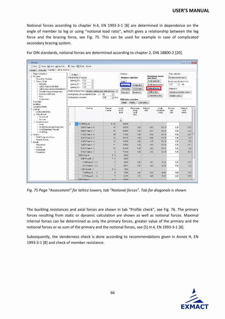
Notional forces according to chapter H.4, EN 1993-3-1 [8] are determined in dependence on the
angle of member to leg or using “notional load ratio”, which gives a relationship between the leg
force and the bracing force, see Fig. 75. This can be used for example in case of complicated
secondary bracing system.
For DIN standards, notional forces are determined according to chapter 2, DIN 18800-2 [20].
Fig. 75 Page “Assessment” for lattice towers, tab “Notional forces”. Tab for diagonals is shown.
The buckling resistances and axial forces are shown in tab “Profile check”, see Fig. 76. The primary
forces resulting from static or dynamic calculation are shown as well as notional forces. Maximal
internal forces can be determined as only the primary forces, greater value of the primary and the
notional forces or as sum of the primary and the notional forces, see (5) H.4, EN 1993-3-1 [8].
Subsequently, the slenderness check is done according to recommendations given in Annex H, EN
1993-3-1 [8] and check of member resistance.

67
USER’S MANUAL
Fig. 76 Page “Assessment” for lattice towers, tab “Profile check”. Tab for diagonals is shown.
The check of joints is carried out in tab “Connections”, see Fig. 77. The connection resistances are
defined on page “Connections”, see Fig. 16. In column “connection” user selects connection for
single member from connections defined on page “Connections”.
Fig. 77 Page “Assessment” for lattice towers, tab “Connections”. Tab for diagonals is shown.

68
USER’S MANUAL
Primary axial forces in dumb elements are checked in tab “Dumb element check”, see Fig. 78.
Fig. 78 Page “Assessment” for lattice towers, tab “Dumb element check”. Tab for horizontals is shown.

69
USER’S MANUAL
Horizontal deflection check and rotation check is carried out in tabs depicted in Fig. 79, resp. Fig. 80.
Fig. 79 Page “Assessment” for lattice towers, tab “Horizontal deflection”
Fig. 80 Page “Assessment” for lattice towers, tab “Rotation”

70
USER’S MANUAL
Ultilization overwiew of profiles and connections is depicted in tabs presented in Fig. 81, resp. Fig.
82. Overall check review is shown in tab “Total”, see Fig. 83.
Fig. 81 Page “Assessment” for lattice towers, tab Utilization overview of “Profiles”
Fig. 82 Page “Assessment” for lattice towers, tab Utilization overview of “Connections”

71
USER’S MANUAL
Fig. 83 Page “Assessment” for lattice towers, tab “Total”
7.9.4 Assessment – monopoles and chimneys
The resistance of members and their check is determined on the page “Assessment”, see Fig. 84.
The page is composed of several tabs. Tabs “Cross section classification”, “Resultant characteristics”,
“Characteristic buckling resistance in compression”, “Characteristic buckling resistance in shear”,
“Resistance of cross-sections”, “Maximum forces” and “Cross section check” are prepared for bottom
and top points of elements.
Cross sections are classified and openings can be defined first. It is assumed that edges of opening
are stiffened and rigidity of stiffener allows use the same class as for cross section without opening.

72
USER’S MANUAL
Fig. 84 Page “Assessment” for monopoles and chimneys, tab “Cross section classification”. Tab for bottom points is shown.
The cross section characteristics with influence of opening are evaluated in tab “Resultant
characteristics”, see Fig. 85.

73
USER’S MANUAL
Fig. 85 Page “Assessment” for monopoles and chimneys, tab “Resultant characteristics”. Tab for bottom points is shown.
If class of cross section is 4, the cross section resistance is determined according to EN 1993-1-6 [6]
or DIN 18800-4 [21]. The buckling resistances in compression and shear are calculated in tabs
“Characteristic buckling resistance in compression”, see Fig. 86 and “Characteristic buckling
resistance in shear”, see Fig. 87.
Fig. 86 Page “Assessment” for monopoles and chimneys, tab “Characteristic buckling resistance in compression”. Tab for bottom points is shown.

74
USER’S MANUAL
Fig. 87 Page “Assessment” for monopoles and chimneys, tab “Characteristic buckling resistance in shear”. Tab for bottom points is shown.
The resitances of cross sections of class 1-3 are determined according to EN 1993-1-1 [5] or DIN
18800-1 [19]. The review of cross section resistances is shown in tabs “Bottom resistance of cross
sections”, see Fig. 88, and “Top resistance of cross sections”.
Fig. 88 Page “Assessment” for monopoles and chimneys, tab “Resistance of cross sections”. Tab for bottom points is shown.

75
USER’S MANUAL
The recapitulation of maximamum forces is shown in tabs “Maximum forces” for bottom and top
points of panels, see Fig. 89.
Fig. 89 Page “Assessment” for monopoles and chimneys, tab “Maximum forces”. Tab for bottom points is shown.
Utilization of cross section is shown in tab “Cross section check”, see Fig. 90.

76
USER’S MANUAL
Fig. 90 Page “Assessment” for monopoles and chimneys, tab “Cross section check”. Tab for bottom points is shown.
The check of joints is carried out in tab “Connections”, see Fig. 91. The connection resistances are
defined on page “Connections”, see chapter 7.3.11. In column “connection” user selects connection
for single node from connections defined on page “Connections”.
Fig. 91 Page “Assessment” for monopoles and chimneys, tab “Connection check”

77
USER’S MANUAL
Horizontal deflection check and rotation check is carried out in tabs depicted in Fig. 92, resp. Fig. 93.
Fig. 92 Page “Assessment” for monopoles and chimneys, tab “Horizontal deflection check”
Fig. 93 Page “Assessment” for monopoles and chimneys, tab “Rotation check”

78
USER’S MANUAL
Overall check review is shown in tab “Check”, see Fig. 94.
Fig. 94 Page “Assessment” for monopoles and chimneys, tab “Check”
7.9.5 Foundation
Resistance of foundation base and stability of tower and pad according to EN 1997-1 [10] is checked
on this page. Limit state GEO (bearing resistance and sliding resistance in foundation base) is situated
on the left side of page, on the right side there is limit state EQU (overall stability), see Fig. 95. On
upper part of page user can see design values of loads in anchoring level. Impact of loads is
computed for all wind directions and load combinations. Maximum utilization of both limit states is
given on the top of page.
In case of towers, where only wind direction 0° is computed (monopoles and chimneys), for tower
assessment direction 45° is added for foundation assessment.
For DIN standards characteristic value of loads in anchoring lever are given. Foundation is checked
according to [22] using safety factors showed on left upper side of page, see Fig. 96.
ATTENTION: Calculation does not include influence of groundwater. If groundwater is present, the
foundation assessment cannot be used.

79
USER’S MANUAL
Fig. 95 Page “Foundation” for EN standard
Fig. 96 Page “Foundation” for DIN standard

80
USER’S MANUAL
8 Report
The report is automatically created. Report templates are prepared in directory “Templates”. The
templates can be alternatively changed according to user requirements. This function is not available
in Demo version.
9 Acknowledgement
The partial support was provided by the project of the Ministry of Industry and Trade of Czech
Republic No. MPO TIP FR-TI3/654 “Advanced methods in design, monitoring and assessment of
slender dynamically loaded structures”.
10 Literature
10.1 General
[1] EN 1990 Eurocode: Basis structural design
[2] EN 1991-1-1 Eurocode 1 - Action on structures – Part 1-1: General actions – Densities, self-weight, imposed load for buildings, 2004
[3] EN 1991-1-3 Eurocode 1 - Action on structures – Part 1-3: General actions – Snow loads, 2013
[4] EN 1991-1-4 Eurocode 1 - Action on structures – Part 1-4: General actions – Wind loads, 2013
[5] EN 1993-1-1 Eurocode 3 – Design of steel structures – Part 1-1: General rules and rules for buildings, 2011
[6] EN 1993-1-6 Eurocode 3 – Design of steel structures – Part 1-6: Strength and stability of shell structures, 2008
[7] EN 1993-1-8 Eurocode 3 – Design of steel structures – Part 1-8: Design of joints, 2013
[8] EN 1993-3-1, Eurocode 3: Design of steel structures – Part 3-1: Towers, masts and chimneys – Towers and masts, 2008
[9] EN 1993-3-2, Eurocode 3: Design of steel structures – Part 3-2: Towers, masts and chimneys – Chimneys, 2008
[10] EN 1997-1, Eurocode 7: Geotechnical design – Part 1: General rules
[11] EN 1090-2 Execution of steel structures and aluminium structures – Part 2: Technical requirements for steel structures, 2012
[12] ISO 12494 Atmospheric icing on structures, 2010
[13] ČSN 73 0035, Actions on structures, 1986

81
USER’S MANUAL
[14] ČSN 73 1430 Design of steel constructions, 1984 (with modification for use with [13] 1986)
[15] Koloušek, V., Pirner, M., Fischer, and O, Náprstek, J., Wind Effects on Civil Engineering Structures, Academia, Praha 1983, Elsevier, coed. London 1984
[16] Lahodný, J., Janata, V.,: Full-scale measurements of towers and masts and comparison with theoretical simplified analysis, Journal of International Association for Shell and Spatial Structures, Vol. 55 (2014) No. 2, June n. 180, pp. 107-116
[17] DIN 4131: Steel radio towers and masts, 11/1991
[18] DIN 1055-5: Design loads for buildings; Live loads – Snow load and ice load, 06/1975
[19] DIN 18800-1: Structural steelwork; Design and construction, 11/1990
[20] DIN 18800-2: Structural steelwork; Analysis of safety against buckling of linear members and frames, 11/1990
[21] DIN 18800-4: Structural steelwork; Analysis of safety against buckling of shells, 11/1990
[22] DIN 1054: Subsoil; Permissible Loading of Subsoil, 11/1976
[23] Petersen, Ch.: Stahlbau: Grundlagen der Berechnung und baulichen Ausbildung von Stahlbauten, 2., verbesserte Auflage, Vieweg, Braunschweig, 1990, ISBN 3-528-18837-5
10.2 National annexes of eurocode
10.2.1 Czech Republic
[CZE1] ČSN EN 1990/NA: 2015-05
[CZE2] ČSN EN 1991-1-1/NA: 2004-03
[CZE3] ČSN EN 1991-1-3/NA: 2013-06
[CZE4] ČSN EN 1991-1-4/NA: 2013-07
[CZE5] ČSN EN 1993-1-1/NA: 2011-07
[CZE6] ČSN EN 1993-1-6/NA: 2008-09
[CZE7] ČSN EN 1993-1-8/NA: 2013-11
[CZE8] ČSN EN 1993-3-1/NA: 2008-09
[CZE9] ČSN EN 1993-3-2/NA: 2008-09
[CZE10] ČSN EN 1997-1/NA: 2006-09

82
USER’S MANUAL
10.2.2 Germany
[DEU1] DIN EN 1990/NA: 2010-12
[DEU2] DIN EN 1991-1-4/NA: 2010-12
[DEU3] DIN EN 1993-1-1/NA: 2015-08
[DEU4] DIN EN 1993-3-1/NA: 2015-11
[DEU5] DIN EN 1993-3-2/NA: 2010-12