structural design project of super tall building chicago spire
DESCRIPTION
Structural Design Project of Super Tall Building Chicago SpireTRANSCRIPT

7/17/2019 Structural Design Project of Super Tall Building Chicago Spire
http://slidepdf.com/reader/full/structural-design-project-of-super-tall-building-chicago-spire 1/474
CHICAGO SPIRE
Chicago, Illinois
2011 – 2012
ASPIRE
Master of Engineering
Structural Design Project

7/17/2019 Structural Design Project of Super Tall Building Chicago Spire
http://slidepdf.com/reader/full/structural-design-project-of-super-tall-building-chicago-spire 2/474
Page left blank intentionally.

7/17/2019 Structural Design Project of Super Tall Building Chicago Spire
http://slidepdf.com/reader/full/structural-design-project-of-super-tall-building-chicago-spire 3/474
ASPIRE PROJECT TEAM
Joseph BeaudetteCornell University
Canton, New York
J. David MuenchUniversity of Massachusetts – Amherst
Medway, Massachusetts
Connor Bruns
Project Leader
Cornell University
Potomac, Maryland
Catherine T. Mulhern
Project Leader
Smith College
Winchester, Massachusetts
Joseph A. Caccio Jr
Cornell University
Monroe Township, New Jersey
Stephanie Richmond
Cornell University
Ellicott City, Maryland
Nicholas Chack
Columbia University
New York, New York
Kristy L. Scales
Syracuse University
Berkshire, New York
Katherine McEntee Coumes
Cornell University
Boston Heights, Ohio
Tom Shouler
Project Leader
Cornell University
Smithtown, New York
Jonathan Dobrin
Cornell University
Montreal, Quebec
Neelang Tiwari
MS Ramaiah Institute of Technology
Indore, M.P., India
Diana Foster
Cornell University
Wilmette, Illinois
Alex Vandenbergh
Cornell University
State College, Pennsylvania
Jeffrey Liu
Pennsylvania State University
Staten Island, New York
Chung Yu Wang
Cornell University
Taipei, Taiwan
Dan Lu
Cornell University
Potomac, Maryland
Muzi Zhu
Tianjin University
Tianjin, China
Sh d h Sh d Ph D

7/17/2019 Structural Design Project of Super Tall Building Chicago Spire
http://slidepdf.com/reader/full/structural-design-project-of-super-tall-building-chicago-spire 4/474
ACKNOWLEDGEMENTS
The 2011-2012 Master of Engineering project team, ASPIRE, would like to thank our professional
advisors from Thornton Tomasetti, Chicago: John Peronto (Associate), and Mary Williams (Senior
Engineer). Mr. Peronto and Ms. Williams volunteered significant time to provide guidance and
structure to our project. Their technical knowledge of structural engineering specific to tall
buildings played an instrumental role in our project.
ASPIRE would also like to thank our faculty advisor, Dr. Shideh Shadravan, for her daily support.
Dr. Shadravan provided both project team and individual guidance vital to our development asMasters students.
The design team would also like to thank the support staff of MIDAS Information Technology Co.
for the assistance and troubleshooting with the MIDAS GEN 3D structural modeling software.
Finally, we would like to acknowledge the Cornell University Department of Civil and
Environmental Engineering faculty and staff. In particular, we would like to thank Professor
Christopher Earls, Professor Ken Hover, Professor T.D. O’Rourke, Cameron Wilkens, Paul Charles,and Karen Browning.

7/17/2019 Structural Design Project of Super Tall Building Chicago Spire
http://slidepdf.com/reader/full/structural-design-project-of-super-tall-building-chicago-spire 5/474
EXECUTIVE SUMMARY
ASPIRE designed the gravity, lateral, and foundation systems, utilized finite element software forstructural optimization, designed steel and concrete connections, and studied the effects of creep
and shrinkage during a year-long analysis of the Chicago Spire.
Preliminary analysis included research of different lateral load resisting systems in order to select
the system that would best suit the needs of the structure. The lateral system chosen was a central
concrete core with outriggers and belt trusses connecting the core with the exterior steel columns.
The gravity design of the structure explored the use of non-composite and composite beams andcolumns in the Spire. ASPIRE selected steel beams with a composite metal decking system. A
column load takedown based on tributary areas was used for the preliminary column design.
The Chicago Spire was modeled using MIDAS Gen, a structural finite element software, to accurately
understand the lateral behavior of the building. A sensitivity analysis was performed to resize the
concrete core, the outriggers, and the belt truss members from the initial hand calculation sizes.
Core wall thicknesses were optimized across the height of the building. Vertical columns and
transfer columns were redesigned as a series of steel built-up shapes through energy optimization
methods.
The foundation system featured the design of a seven level below-grade parking garage and a
retaining wall along the site perimeter. Rock-socketed caissons were designed to support the
tower, extending from the base of the building to the bedrock 119 feet below grade.
There are hundreds of connections in the Chicago Spire ranging from standard steel connections tocomplex designs for the outriggers and the lobby level mega-columns. Several steel-to-steel and
composite connections were designed throughout the tower.
A study of concrete creep and shrinkage estimated differential settlement between the concrete
core and the exterior steel columns using the GL2000 model. Creep and shrinkage are dependent
on variables such as loading schedule, curing period, and material properties, making it difficult to
predict the actual amount of creep and shrinkage. However, failure to acknowledge these effects
leads to cracks in the concrete and uneven floors.
Through the course of the project, ASPIRE faced many challenges that required the design team to
seek guidance from outside sources, including weekly meetings with our faculty advisor and bi-
weekly conference calls with our professional advisors from Thornton Tomasetti. The structural
design of the Chicago Spire was a collaborative effort of eighteen students and the advisors The

7/17/2019 Structural Design Project of Super Tall Building Chicago Spire
http://slidepdf.com/reader/full/structural-design-project-of-super-tall-building-chicago-spire 6/474
Page left blank intentionally.

7/17/2019 Structural Design Project of Super Tall Building Chicago Spire
http://slidepdf.com/reader/full/structural-design-project-of-super-tall-building-chicago-spire 7/474
TABLE OF CONTENTS
ASPIRE PROJECT TEAM .......................................................................................................................................................... i
ACKNOWLEDGEMENTS ........................................................................................................................................................ ii
EXECUTIVE SUMMARY ........................................................................................................................................................ iii
TABLE OF CONTENTS............................................................................................................................................................. v
LIST OF FIGURES ............................................................................................................................................................... viii8
LIST OF TABLES ...................................................................................................................................................................... xi
1.0 Introduction ............................................................................................................................................................... 1
1.1 Chicago Spire: Background and Location ................................................................................................. 2
1.2 Project Scope ........................................................................................................................................................ 3
1.3 Design Process ..................................................................................................................................................... 4
2.0 Design Criteria .......................................................................................................................................................... 5
2.1 Tall Building Design........................................................................................................................................... 5
2.2 Lateral System Determination ...................................................................................................................... 6
2.3 Typical Floors and Column Layouts ........................................................................................................... 8
2.4 Gravity Design Loads ........................................................................................................................................ 9
2.5 Lateral Design Loads ....................................................................................................................................... 10
2.6 Load Combinations .......................................................................................................................................... 13
2.7 Serviceability Requirements ........................................................................................................................ 14
3.0 Gravity Design ......................................................................................................................................................... 16

7/17/2019 Structural Design Project of Super Tall Building Chicago Spire
http://slidepdf.com/reader/full/structural-design-project-of-super-tall-building-chicago-spire 8/474
3.5 Façade Beam Design ........................................................................................................................................ 27
3.6 Column Design ................................................................................................................................................... 28
4.0 Lateral Load Resisting System Design .......................................................................................................... 33
4.1 Structural System Overview ........................................................................................................................ 34
4.2 Preliminary Core Wall Design ..................................................................................................................... 36
4.3 Auxiliary Lateral Systems ............................................................................................................................. 41
4.4 Finite Element Model ...................................................................................................................................... 45
4.5 Core Wall Reinforcement Design ............................................................................................................... 52
4.6 Energy Optimization ....................................................................................................................................... 53
4.7 Eigenvalue Analysis ......................................................................................................................................... 56
5.0 Steel and Concrete Detailing ............................................................................................................................. 59
5.1 Typical Connections ........................................................................................................................................ 60
5.2 Complex Connections ..................................................................................................................................... 65
6.0 Foundation Design and Detailing .................................................................................................................... 72
6.1 Soil Properties ................................................................................................................................................... 73
6.2 Retaining Wall Design..................................................................................................................................... 74
6.3 Parking Garage Slab Design.......................................................................................................................... 75
6.4 Bell Caisson Design .......................................................................................................................................... 76
6.5 Rock-Socketed Caisson ................................................................................................................................... 77
7.0 Long-Term Deflection Effects ........................................................................................................................... 82
7 1 C l S 83

7/17/2019 Structural Design Project of Super Tall Building Chicago Spire
http://slidepdf.com/reader/full/structural-design-project-of-super-tall-building-chicago-spire 9/474
9.0 Appendix ................................................................................................................................................................... 94
9.1 Gravity Design Loads ...................................................................................................................................... 95
9.2 RWDI Recommended Wind Load .............................................................................................................. 96
9.3 Seismic Load Summary ............................................................................................................................... 101
9.4 Core Slab Design Summary ....................................................................................................................... 105
9.5 Link Beam Summary .................................................................................................................................... 106
9.6 Beam Spans and Tributary Areas ........................................................................................................... 109
9.7 Slab and Decking Summary ....................................................................................................................... 110
9.8 Composite Beam Summary ....................................................................................................................... 111
9.9 Initial Gravity Design Column Comparison ........................................................................................ 112
9.10 MIDAS Gen Gravity Loads .......................................................................................................................... 113
9.11 Column Validation Summary .................................................................................................................... 117
9.12 MIDAS Sensitivity Analyses ....................................................................................................................... 118
9.13 Core Wall Reinforcement ........................................................................................................................... 121
9.14 Creep and Shrinkage .................................................................................................................................... 122
10.0 Drawings ..................................................................................................................................... C-2.001 - S-4.004
11.0 Calculations ................................................................................................................................................. C1-C297

7/17/2019 Structural Design Project of Super Tall Building Chicago Spire
http://slidepdf.com/reader/full/structural-design-project-of-super-tall-building-chicago-spire 10/474
LIST OF FIGURES
Figure 1.1: Chicago Spire ...................................................................................................................................................... 1
Figure 1.2: Chicago Spire Site Location .......................................................................................................................... 2
Figure 1.3: Bank Location .................................................................................................................................................... 4
Figure 2.1: Outrigger and Belt Truss System Sketch (Taranath 1988, 279) ................................................... 6
Figure 2.2: RWDI Wind Tunnel versus ASCE7 Directional Procedure Forces ............................................. 11
Figure 3.1: Structural Beam Labeling System ............................................................................................................ 18
Figure 3.2: Tributary Area Breakdown for External Bays .................................................................................... 19
Figure 3.3: Tributary Area for Joist 1 ............................................................................................................................ 19
Figure 3.4: Gravity Load Paths for Design Process .................................................................................................. 20
Figure 3.5: Core Slab Detail ............................................................................................................................................... 21
Figure 3.6: Core Slab Design Locations, Directions, and Numbering ............................................................... 21
Figure 3.7: Tributary Areas for Link Beam Design. ................................................................................................. 22
Figure 3.8:Typical Composite Beam and Decking System .................................................................................... 24
Figure 3.9: Tributary Areas for the HSS Beam .......................................................................................................... 27
Figure 3.10: Steel Column Load Paths .......................................................................................................................... 29
Figure 3.11: Bank 3 Steel Column Layout.................................................................................................................... 29
Figure 3.12: Bank 1 Steel Column Layout.................................................................................................................... 30
Figure 3.13: Typical Core Column Section, Banks 1-3 ............................................................................................ 31
Figure 3.14: Composite Column Section ...................................................................................................................... 32

7/17/2019 Structural Design Project of Super Tall Building Chicago Spire
http://slidepdf.com/reader/full/structural-design-project-of-super-tall-building-chicago-spire 11/474
Figure 4.4: Outriggers Spanning Two Mechanical Floors ..................................................................................... 41
Figure 4.5: Compression Block and Steel Strain from Weak Axis Bending ................................................... 47
Figure 4.6: Initial Discontinuity Check under Gravity Loads .............................................................................. 48
Figure 4.7: a) BU1 and b) BU2 .......................................................................................................................................... 49
Figure 4.8: Discontinuity Test Comparison between Original and Final Design ........................................ 50
Figure 4.9: Deformed Shape for 50 year MRI Wind Loads (NTS) ...................................................................... 51
Figure 4.10: Optimization Material Use versus % Reduction of Drift ............................................................. 55
Figure 4.11: From Left to Right: a) Mode Shape 1; b) Mode Shape 2; c) Mode Shape 3 .......................... 58
Figure 5.1: a) Elevation and b) Plan of Typical Welded Column Splice .......................................................... 60
Figure 5.2: Elevation of Floor Joist to Girder Connection ..................................................................................... 61
Figure 5.3: Elevation of HSS Beam to Cantilever Connection.............................................................................. 61
Figure 5.4: Elevation of Built-up Column to Radial Girder and Cantilever Connection ........................... 62
Figure 5.5: Elevation of Circumferential Girder to Column Plate Connection ............................................. 63
Figure 5.6: a) Elevation and b) Section of Radial Girder to Core Wall Connection .................................... 64
Figure 5.7: 3D Rendering of Base of Mega-Column to Caisson Connection .................................................. 66
Figure 5.8: Bottom of Outrigger Connection .............................................................................................................. 67
Figure 5.9: Elevation of Outrigger and Radial Girder Connection to Concrete Core ................................. 68
Figure 5.10: a) Embedded Steel Frame and b) Cross Bracing and Point Loads .......................................... 69
Figure 5.11: 3D Rendering of Mega-Column Connection ...................................................................................... 70
Figure 5.12: Singular Transfer Column Connection Front and Side Elevation ............................................ 71
Fi 5 13 S li T f C l C i F d Sid El i 71

7/17/2019 Structural Design Project of Super Tall Building Chicago Spire
http://slidepdf.com/reader/full/structural-design-project-of-super-tall-building-chicago-spire 12/474
Figure 6.4: Elevation of Rock-Socketed Caissons ..................................................................................................... 77
Figure 6.5: Detail of Caisson .............................................................................................................................................. 78
Figure 6.6: Limit states from Left to Right: a) Stress, b) Settlement and c) Uplift ...................................... 78
Figure 6.7: Elevation of Ring Beam ................................................................................................................................ 79
Figure 6.8: Plan View of Ring Beam Resistance to Soil Pressure ....................................................................... 79
Figure 6.9: a) Compression and b) Tension Stresses in Rock-Socketed Caisson ........................................ 80
Figure 7.1: Concrete Strength Gain with Time .......................................................................................................... 84
Figure 7.2: Concrete Elastic Modulus Gain with Time ........................................................................................... 84
Figure 7.3: Initial Strength Gain of Concrete for Various Cement Types........................................................ 87
Figure 7.4: Typical Strain Values for a Single Floor ................................................................................................ 88
Figure 7.5: Core Deformations per Floor ..................................................................................................................... 89
Figure 7.6: Total Core Displacement over Time ....................................................................................................... 91
Figure 9.1: Built Up Column Sensitivity Results to Dead Load ........................................................................ 119
Figure 9.2: Core Wall Thickness Sensitivity Results to Dead Load ................................................................ 120
Figure 9.3: Belt Truss and Outrigger Sensitivity ................................................................................................... 120

7/17/2019 Structural Design Project of Super Tall Building Chicago Spire
http://slidepdf.com/reader/full/structural-design-project-of-super-tall-building-chicago-spire 13/474
LIST OF TABLES
Table 1.1: Floor Bank Summary ........................................................................................................................................ 4
Table 2.1: Summary of Exterior Columns per Bank .................................................................................................. 8
Table 2.2: Unfactored Design Loads per ASCE 7-05 (psf) ....................................................................................... 9
Table 2.3: Seismic Lateral Forces .................................................................................................................................... 12
Table 3.1: Typical Values for Vibrational Analysis Calculations ........................................................................ 26
Table 3.2: Summary of Estimated Vibrations ............................................................................................................ 26
Table 3.3: HSS Beam Design Summary ......................................................................................................................... 27
Table 3.4: Factored Loads from Gravity at Ground Level ..................................................................................... 31
Table 4.1: Critical Core Wall Unfactored Design Loads ......................................................................................... 36
Table 4.2: Controlling Stresses for Core Wall Design ............................................................................................. 38
Table 4.3: Initial Core Wall Reinforcement Requirements .................................................................................. 40
Table 4.4: Initial Core Thickness by Bank ................................................................................................................... 40
Table 4.5: Summary of Column Properties for each Column Section .............................................................. 43
Table 4.6: Stress Reduction in each Bank from Outriggers .................................................................................. 43
Table 4.7: Summary of Core Wall Thicknesses with Outriggers and Columns ............................................ 43
Table 4.8: System Stiffness Summary ........................................................................................................................... 44
Table 4.9: Initial MIDAS Model Element Properties ............................................................................................... 45
Table 4.10: Final MIDAS Model Element Properties ............................................................................................... 48
Table 4.11: Initial and Final MIDAS Results ............................................................................................................... 50

7/17/2019 Structural Design Project of Super Tall Building Chicago Spire
http://slidepdf.com/reader/full/structural-design-project-of-super-tall-building-chicago-spire 14/474
Table 6.1: Critical Von Mises Stresses from ABAQUS Model ............................................................................... 81
Table 7.1: Cement Type Deformation Sensitivity Analysis .................................................................................. 86
Table 7.2: Core Total Deformations ............................................................................................................................... 88
Table 7.3: 20-Year Deformation Comparisons .......................................................................................................... 90
Table 9.1: RWDI Wind Load Combinations ................................................................................................................ 96
Table 9.2: RWDI Provided Wind Forces and Torsional Moments ..................................................................... 97
Table 9.3: Link Beam Dimensions ............................................................................................................................... 106
Table 9.4: Residential and Lobby Link Beam Summary ..................................................................................... 107
Table 9.5: Mechanical Floor Link Beam Summary ............................................................................................... 108
Table 9.6: Decking and Slab Thickness Summary for Composite Beam System ...................................... 110
Table 9.7: Unfactored Dead Load for Composite Beam System ...................................................................... 110
Table 9.8: Composite Beam Summary ....................................................................................................................... 111
Table 9.9: Initial Composite and Steel Column Comparison............................................................................. 112
Table 9.10: MIDAS Gen Unfactored Gravity Loads (kips / node) ................................................................... 113
Table 9.11: Composite and Steel Shapes for Lateral Design Column Validation...................................... 117
Table 9.12: Built-up Steel and Concrete Properties ............................................................................................. 118
Table 9.13: Sensitivity Analyses Element Properties .......................................................................................... 119
Table 9.14: Core Wall Reinforcement Details ......................................................................................................... 121
Table 9.15: Concrete Core Properties ........................................................................................................................ 126
Table 9.16: Steel Deflection Summary ....................................................................................................................... 126
T bl 9 17 H idi D f Chi 127

7/17/2019 Structural Design Project of Super Tall Building Chicago Spire
http://slidepdf.com/reader/full/structural-design-project-of-super-tall-building-chicago-spire 15/474
Page left blank intentionally.

7/17/2019 Structural Design Project of Super Tall Building Chicago Spire
http://slidepdf.com/reader/full/structural-design-project-of-super-tall-building-chicago-spire 16/474

7/17/2019 Structural Design Project of Super Tall Building Chicago Spire
http://slidepdf.com/reader/full/structural-design-project-of-super-tall-building-chicago-spire 17/474
1.0 INTRODUCTION
1.0 Introduction
The 2011-2012 Master of Engineering Structural Design Project was the structural design of theChicago Spire (Figure 1.1), located on the west side of Lake Shore Drive in Chicago, Illinois. The
project was provided by John Peronto, P.E. and Mary Williams, P.E. of Thornton Tomasetti’s Chicago
office. Cornell University Lecturer Dr. Shideh Shadravan was the project advisor. The project team
consisted of sixteen Master of Engineering students and two undergraduates. The team members
provided a unique assortment of design experience, academic specialty, and cultural background.
This resulted in a realistic, professional experience similarly found at a design firm.

7/17/2019 Structural Design Project of Super Tall Building Chicago Spire
http://slidepdf.com/reader/full/structural-design-project-of-super-tall-building-chicago-spire 18/474
1.0 INTRODUCTION
1.1 Chicago Spire: Background and Location
The Chicago Spire is 2,000 ft tall on a strip of land between the Ogden Slip and the mouth of theChicago River (Figure 1.2). The tower contains approximately 3 million square feet of upscale
condominiums and amenities. The basement has 7 below-grade parking levels on top of rock
socketed caissons. The structural engineer of record was Thornton Tomasetti. The project was put
on hold in 2008 with only its foundation completed. Upon completion, the Chicago Spire would be
the tallest building in the Western Hemisphere.
Spanish architect Santiago Calatrava was the architect and engineer for the project. The design
highlights a spiraling exterior supported by an exterior column grid and a concrete core. Calatrava
compared the design to an imaginary smoke stack from a campfire lit by the indigenous Native
American tribes of Chicago.
i h

7/17/2019 Structural Design Project of Super Tall Building Chicago Spire
http://slidepdf.com/reader/full/structural-design-project-of-super-tall-building-chicago-spire 19/474
1.0 INTRODUCTION
1.2 Project Scope
The Master of Engineering team was charged with providing a complete structural design of thegravity and lateral system as well as foundation design, connections and details, and an analysis of
the effects from creep and shrinkage. The project required the eighteen team members to
collaborate as sub-teams to complete assigned deliverables, utilizing full engineering knowledge
and experience. The design of the cylindrical superstructure entailed expanding design limits into
unfamiliar areas through self-learning and provided resources.
The design project was split into ten deliverables through the academic school year. Deliverables
include submittal of white-paper reports, annotated engineering calculations, structural drawings,
and finite element models. Local and professional advisors provided design support through bi-
weekly teleconferences and daily correspondence.
Structural design was supplemented by academic field trips pertinent to tall building design.
ASPIRE traveled to New York City in November of 2011. This trip included a presentation by
Silverstein Properties and a site tour of Four World Trade Center, a 72-story skyscraper designed
by Leslie E. Robertson and Associates. In December 2011, team members visited the Rowan,Williams, Davies, Inc. (RWDI) wind tunnel testing facility in Guelph, Ontario, Canada. RWDI is a
leader in the field of wind tunnel testing, and has performed dynamic analysis for some of the
world’s tallest structures, including the Chicago Spire.

7/17/2019 Structural Design Project of Super Tall Building Chicago Spire
http://slidepdf.com/reader/full/structural-design-project-of-super-tall-building-chicago-spire 20/474
1.0 INTRODUCTION
1.3 Design Process
The structural design process began in August of 2011. ThorntonTomasetti provided ASPIRE with architectural geometry and a structural
elevation. A geotechnical report from STS Consultants, LTD and wind
tunnel testing results from RWDI were also provided. Co-project managers
were elected to oversee and organize the design approach for each
deliverable. They held weekly meetings, compiled deliverable
submissions, critiqued design tools, and served as the primary liaison to
the project advisors.
Initial design consisted of determining a lateral system and overall design
criteria including serviceability limits and load conditions. The structure is
split into four banks (Figure 1.3). The bottom of each bank consists of a
lobby level and the top of each bank consists of two mechanical levels.
Bank 1 is an exception where the ground floor lobby spans four floors for a
large open space atrium. Bank 4 was further split into two sub-banks for
design optimization as the structure’s tapering increases significantly at
floor 139. Table 1.1 summarizes the floor breakup per bank.
Table 1.1: Floor Bank Summary
Bank Floors
1 1-39
2 40-73
3 74-110
4.1 111-129
4.2 130-147
Revit Structure was used to construct a preliminary three dimensional
model. Element shapes and sizes were updated throughout the design
process. Initially, Revit was utilized to produce structural drawings;however, AutoCAD 2012 was ultimately used for the final drawings due to
inadequate computer graphic and RAM resources for Revit.
All structural elements were initially designed for gravity forces, and ultimately optimized using
MIDAS G h di i l l f l Th j hi hli h d i i
Figure 1.3: Bank Location
B a n k
1
B a n k
2
B a n k
3
B a n k
4

7/17/2019 Structural Design Project of Super Tall Building Chicago Spire
http://slidepdf.com/reader/full/structural-design-project-of-super-tall-building-chicago-spire 21/474
2.0 DESIGN CRITERIA
2.0 Design Criteria
Preliminary analyses required ASPIRE to study relevant tall building design. In adjunction witharchitectural constraints, this research was utilized to select specific structural systems for gravity
and lateral systems.
2.1 Tall Building Design
For years engineers have furthered the practice of structural engineering, designing increasingly
taller skyscrapers to meet the demanding vision of architects and owners. As buildings grow, more
efficient, specialized structural systems are needed to handle the loads. One of the first buildings to
clearly demonstrate the potential of the skyscraper was the Empire State Building, reaching 1250
feet in 1931 through the use of a standard riveted steel frame with simple portal bracing (Binder
2006, 42). Engineering has progressed onward from this simple system, reducing the amount of
material used while simultaneously increasing the height. One way of achieving this is through the
use of a high-density concrete core with outriggers and belt trusses at mechanical floors. This
strategy has allowed buildings like the Shanghai World Finance Center and the Burj Khalifa to soar
to heights over one and two thousand feet, respectively.
The Chicago Spire’s specifications are demanding, defining a building that is truly unique.
Outriggers and belt trusses for lateral restraint are limited to the mechanical floors, isolated
throughout the structures elevation. The residential floors contain spacious floor plans with evenly
spaced columns in a ring around the core. Cantilever beams extend from the radial frame to the
façade, allowing for unobstructed views in all directions.
For a building as slender as the Chicago Spire, the lateral system is often the limiting factor in
selecting a design. As buildings increase in height, the structural frames continue to decrease in
average weight per square foot. This is possible due to interaction between interior/exterior
components; high strength low-alloy steel; composite construction; wind tunnel tests; and concrete
improvements in reinforcement and strength.
A vital piece of the Chicago Spire’s design is a system to resist lateral loads. Lateral loads are more
variable than gravity loads and increase significantly with building height. Lateral systems are
designed with the tower’s strength, stability, and rigidity in mind. For tall buildings, serviceability
usually controls the design. Inter-story deflection, also called floor-to-floor drift, and dynamic
effects, such as vortex shedding and vibrations, are concerns for slender buildings.

7/17/2019 Structural Design Project of Super Tall Building Chicago Spire
http://slidepdf.com/reader/full/structural-design-project-of-super-tall-building-chicago-spire 22/474
2.0 DESIGN CRITERIA
2.2 Lateral System Determination
The Chicago Spire’s architecture plays a significant role in selecting a feasible lateral system.Clearance requirements in residential and lobby floors limit regions where the exterior column grid
and concrete core can integrate to resist lateral forces. The two primary components of the chosen
lateral system are the high-strength concrete core and the exterior column system.
2.2.1 Outriggers and Belt Trusses
Mechanical floors will include outriggers and belt trusses to effectively stiffen the structure and
incorporate the exterior column grid with the core. The outriggers will span from each exterior
column to the core wall two floors above. Belt trusses will circle the structure at the same floors.
Belt trusses enable the column grid to systematically resist induced shear forces and moments. The
lack of architectural constraints in mechanical floors allows for large steel members to span in
regions normally occupied in residential floors. The outriggers and belt trusses are effective in
reducing both inter-story and global drift. Additionally, these transfer a 20-40% of the exterior
axial forces into the concrete core.
Outriggers and belt trusses are extremely difficult and timely to construct. However given the
architectural constraints of the project, they are a necessity to meet serviceability requirements.
Construction scheduling must consider the delay and dead time when outriggers floors are erected.
Figure 2.1 shows an outrigger and belt truss system sketch for a typical lateral restraint system.

7/17/2019 Structural Design Project of Super Tall Building Chicago Spire
http://slidepdf.com/reader/full/structural-design-project-of-super-tall-building-chicago-spire 23/474
2.0 DESIGN CRITERIA
2.2.2 Core and Shear Walls
The core of the Chicago Spire will consist of thick concrete shear walls integrated through link
beams and a reinforced concrete, two-way slab.
Concrete is a versatile building material with its own strengths and weaknesses. Concrete is
economic, fire-resistant, and long-lasting. Concrete walls can be almost any shape or size as long as
they harden uniformly to limit cracking. A disadvantage of concrete is the increased section
required to support a specified load. However, this larger section can increase structure stiffness,
decrease global deflection, and minimize floor vibrations.
Another weakness of concrete is the construction time involved with slip formwork erection,
pumping, pouring, and curing. The increased construction time results in increased labor costs,
which should be balanced by material savings.
One important consideration for a concrete core is the effect of creep and shrinkage. With steel or
composite columns, the vertical elements will ultimately experience differential settlement. This
must be pre-calculated and accounted for during construction.
7/17/2019 Structural Design Project of Super Tall Building Chicago Spire
http://slidepdf.com/reader/full/structural-design-project-of-super-tall-building-chicago-spire 24/474
2.0 DESIGN CRITERIA
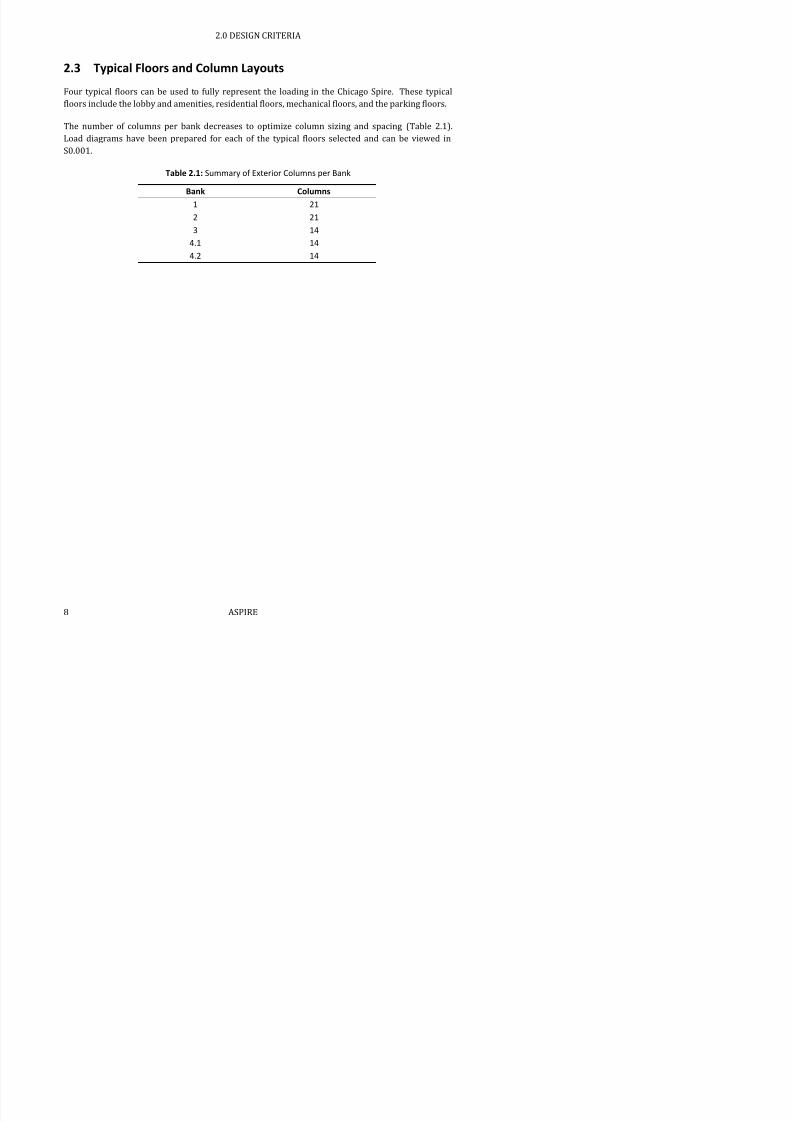
2.3 Typical Floors and Column Layouts
Four typical floors can be used to fully represent the loading in the Chicago Spire. These typicalfloors include the lobby and amenities, residential floors, mechanical floors, and the parking floors.
The number of columns per bank decreases to optimize column sizing and spacing (Table 2.1).
Load diagrams have been prepared for each of the typical floors selected and can be viewed in
S0.001.
Table 2.1: Summary of Exterior Columns per Bank
Bank Columns
1 21
2 21
3 14
4.1 14
4.2 14

7/17/2019 Structural Design Project of Super Tall Building Chicago Spire
http://slidepdf.com/reader/full/structural-design-project-of-super-tall-building-chicago-spire 25/474
2.0 DESIGN CRITERIA
2.4 Gravity Design Loads
Gravity loads include element self-weight as well as superimposed dead loads and live loads asdefined by ASCE 7-05. Loading diagrams look specifically at loads acting on the floor slabs;
detailing which load is applied in a certain area. This information is used to design beams, columns,
and slabs for gravity loads. Loads from column self-weight, lateral forces, and façade line loads are
not included in loading diagrams.
Dead loads include self-weight of reinforced concrete slabs and composite decking when applicable.
Values were updated throughout the design process once all slab thicknesses, concrete densities,
and decking specifications were made. Table 2.2 summarizes the unfactored gravity forces used for
design. Appendix 9.1 displays the calculations for the specific loads in Table 2.2.
Table 2.2: Unfactored Design Loads per ASCE 7-05 (psf)
Dead
Load
Superimposed
Dead Load
Live Load
Lobby 32 57 100
Residential 33 34 55
Mechanical 39 10 240
Parking 150 42 40
Mechanical Core 55 10 240
Residential and Lobby Core 55 57 100

7/17/2019 Structural Design Project of Super Tall Building Chicago Spire
http://slidepdf.com/reader/full/structural-design-project-of-super-tall-building-chicago-spire 26/474
2.0 DESIGN CRITERIA
2.5 Lateral Design Loads
Lateral loads are extremely important in the design of tall buildings, and they are the controllingfactor the Chicago Spire design. Tall and slender structures such as the Spire are extremely
susceptible to wind and seismic forces. ASCE 7-10 was used to estimate wind and seismic forces.
Wind tunnel testing results were also provided and used in comparison to the code defined wind
loads.
2.5.1 ASCE 7-10 Wind Loads
Chapter 26 was utilized to calculate various factors, which include basic wind speed, wind
directionality factor, exposure category, topographic factor, gust effect factor, and enclosure
classification. Chapter 26 calculations can be found in Calculation 2.2.1. The following assumptions
were made throughout the calculation.
Basic wind speed, V = 120 mph ASCE 7-10, 26.5-1B
Wind directionality factor, Kd = 0.85 ASCE 7-10, 26.2-1
Exposure Category D (Flat, unobstructed wind over water) ASCE 7-10, 26.7
Building, Enclosed ASCE 7-10, 26.2
Occupancy Category IV (Iconic structure) ASCE 7-10, 1.5-1
These factors are then used in the Directional Procedure in Chapter 27 to calculate windward andleeward pressures. The main wind force-resisting system from 27.4 is used to calculate the wind
pressures for windward and leeward walls. The code calculated wind pressures were multiplied by
respective lateral tributary areas to produce a net wind force at each floor.
Loads from ASCE 7-10 are very conservative and ambiguous for the Chicago Spire. The calculations
were performed to provide baseline values to compare against wind tunnel data. For code
calculations, the building is assumed to be prismatic and regular-shape, so that windward, leeward,
and side walls can be identified. Effects like vortex shedding are not addressed.
The ASCE 7-10 wind loads are calculated with basic wind speeds corresponding to a mean
recurrence interval of 1700 years. These results should be considered for design only. ASCE 7-10,
Figure CC-3 provides 50-year MRI basic wind speeds which can be used for serviceability criteria.

7/17/2019 Structural Design Project of Super Tall Building Chicago Spire
http://slidepdf.com/reader/full/structural-design-project-of-super-tall-building-chicago-spire 27/474
2.0 DESIGN CRITERIA
2.5.2 RWDI Wind Tunnel Forces
Thornton Tomasetti provided ASPIRE with a wind tunnel analysis of the Chicago Spire. The report,
prepared by RWDI, contained forces (Fx and Fy) and torsional moments (Mz) for each floor. The
report lists recommended wind load combinations which will be discussed in a later section. The
maximum resultant of the combinations for Fx and Fy were plotted against the ASCE 7-10
directional procedure forces. Figure 2.2 shows these results and a confirmation that wind tunnel
forces should be used for strength design and serviceability criteria. Appendix 9.2 shows all RWDI
Wind Tunnel Data and recommended wind load combinations.
The RWDI forces are for a 100-year MRI. For checking serviceability criteria, a reduction factor of0.83 is used to estimate 50-year MRI forces.
Figure 2.2: RWDI Wind Tunnel versus ASCE7 Directional Procedure Forces
2 0 DESIGN CRITERIA

7/17/2019 Structural Design Project of Super Tall Building Chicago Spire
http://slidepdf.com/reader/full/structural-design-project-of-super-tall-building-chicago-spire 28/474
2.0 DESIGN CRITERIA
2.5.3 ASCE 7-10 Seismic Load Calculations
ASCE 7-10, Chapters 11 and 12 were used to estimate seismic loads for the Chicago Spire. The
complete seismic calculations are in Calculation 2.3.
The overall weight of the building was needed to perform seismic loading analysis. The building is
broken down into 8 Mechanical floors, 8 Lobby floors, and 131 Residential floors for a total of 147
floors. The effective seismic weight, W, was calculated using an initial estimate for core wall,
column, and cladding self-weight. Following the design of columns and core walls, the effective
weight and resulting seismic forces were updated. The effective seismic weight was found to be
650,000 kips. The base shear was calculated assuming a seismic response coefficient, Cs, of 0.10.The following formulas were used to determine the seismic lateral loads at each floor.
ASCE 7-10, 12.8-11
∑
( ) ASCE 7-10, 12.8-12
∑ ASCE 7-10, 12.8-13
where
Fx ,Fi = lateral seismic forces induced at any level i or x
Cvx = vertical distribution factor
V = total design lateral base shear
wi , wx = portion of the total effective seismic weight of the structure located to level
i or x
hi , hx are the height from the base to level i or x
k= exponent related to the structure period
Vx = design story shear at any story
Table 2.3 summarizes the results at the base and top floor of the structure. See Appendix 9.3 for all
lateral forces, story shears, and moments.
2 0 DESIGN CRITERIA

7/17/2019 Structural Design Project of Super Tall Building Chicago Spire
http://slidepdf.com/reader/full/structural-design-project-of-super-tall-building-chicago-spire 29/474
2.0 DESIGN CRITERIA
2.6 Load Combinations
The following load combinations from ASCE 7-05, 2.3.2 were used throughout the design process.Load combinations were used in both engineering hand calculations and in the MIDAS Gen 3D
model. The RWDI wind tunnel recommended combinations from Appendix 9.2 were used as a sub-
level of load combinations when wind applied.
1.4D
1.2D + 1.6L
1.2D + 1.6W + 1.0L 1.2D + 1.0E + 1.0L
.9D + 1.6W
.9D + 1.0E
The following load combinations from ASCE 7-05, CC.1.2 were used in for drift serviceability
criteria. The RWDI wind tunnel recommended combinations from Table 9.1 were used as a sub-
level of load combinations with a reduction factor of 1.20.
1.0D + .5L + .7W
2 0 DESIGN CRITERIA

7/17/2019 Structural Design Project of Super Tall Building Chicago Spire
http://slidepdf.com/reader/full/structural-design-project-of-super-tall-building-chicago-spire 30/474
2.0 DESIGN CRITERIA
2.7 Serviceability Requirements
Serviceability limit states are the conditions in which the routine functions of a structure areimpaired because of local deformation of building components or because of occupant discomfort.
These limit states are affected by static loads from the occupants and their possessions, snow or
rain on roofs, temperature, dynamic loads from human activity, wind, or the operation of the
building service equipment. Serviceability criteria for the Chicago Spire should be selected from the
limits specified in design codes to ensure both functional as well as economical design when
constructing a building with desirable retail space.
Serviceability criteria for the Chicago Spire are controlled by:
Excessive deflection or rotation
Excessive vibrations
Total and local (floor-to-floor) building drift
Tower accelerations
The criteria used depend on the function of the building. General guidance on serviceability limitsis provided in sections CC1.1, CC1.2, and CC1.3 of ASCE 7-10.
2.7.1 Deflection
Vertical deflections arise primarily from:
Gravity loads (dead loads and live loads)
Effects of temperature, creep and differential settlement
Construction tolerances and errors
For the Chicago Spire, the deflection limit for horizontal members is as follows:
Δ ≤ L/360 ASCE 7-10, CC1.1
These limits will prevent any visible deflection or impairment of window and door operation. Snow
loads are negligible in the Chicago Spire, thus only dead and live loads are considered when
meeting deflection criteria. The suggested load combination is:
D + L ASCE 7-10, CC-1a

7/17/2019 Structural Design Project of Super Tall Building Chicago Spire
http://slidepdf.com/reader/full/structural-design-project-of-super-tall-building-chicago-spire 31/474

7/17/2019 Structural Design Project of Super Tall Building Chicago Spire
http://slidepdf.com/reader/full/structural-design-project-of-super-tall-building-chicago-spire 32/474
3.0 GRAVITY DESIGN

7/17/2019 Structural Design Project of Super Tall Building Chicago Spire
http://slidepdf.com/reader/full/structural-design-project-of-super-tall-building-chicago-spire 33/474
3.1 Geometry and Loading
The Chicago Spire geometry is based on provided architectural drawings as well as teamassumptions based on design calculations and the elevation drawings. Assumptions for the Chicago
Spire geometry and loading are listed below.
Beam spans and associated tributary areas are calculated from the Revit model.
Two cantilever beam spans (short and long) are considered for each typical floor plan. The spans
are estimated from the provided structural elevation drawing.
Exterior face consists of curved, load bearing HSS beams.
Mechanical and lobby floor plans have three joists per internal bay. Residential floor plans have
two joists per internal bay.
Radial girders and cantilever beams are fixed-fixed to reduce net moment at the respective
connection.
All other beam connections are considered to be simply supported.
3.1.1 Tributary Areas
Joists, circumferential girders, angled girders, and HSS beams bear loads from the design loads
shown in Table 2.2 (pg 9). A floor beam denomination system is shown in Figure 3.1. Calculation
3.1 displays the calculation steps for gravity design tributary area. More specific assumptions for
the tributary area calculations are listed below.
Rectangular shapes are used to estimate all tributary areas.
Column-to-façade distance is assumed to be constant throughout the rise of the tower.
Typical floor plans are considered to have internal bays and external bays.
o Internal bays consist of floor joists and radial girders.
o External bays consist of cantilevers, HSS beams, and angled girders.
HSS 1 extends from the short cantilever to the end of the long cantilever and back down to
another short cantilever. HSS 2 spans between two short cantilevers. See Figure 3.2.
In external bays bounded by HSS 1, the HSS beam bears ¼ of the area, the angled girder bears ½
of the area, and the circumferential girders bears ¼ of the area. See Figure 3.2.
In external bays bounded by HSS 2, the HSS beam bears ½ of the area, and the column girder
bears ½ the area. See Figure 3.2.
3.0 GRAVITY DESIGN

7/17/2019 Structural Design Project of Super Tall Building Chicago Spire
http://slidepdf.com/reader/full/structural-design-project-of-super-tall-building-chicago-spire 34/474
Figure 3.1: Structural Beam Labeling System
HSS 1
HSS 2
3.0 GRAVITY DESIGN

7/17/2019 Structural Design Project of Super Tall Building Chicago Spire
http://slidepdf.com/reader/full/structural-design-project-of-super-tall-building-chicago-spire 35/474
Figure 3.2: Tributary Area Breakdown for External Bays
Figure 3.3 shows the tributary area for a typical joist. The base length is the average adjacent joist
lengths, and the height is the beam spacing.
Figure 3.3: Tributary Area for Joist 1
3.0 GRAVITY DESIGN

7/17/2019 Structural Design Project of Super Tall Building Chicago Spire
http://slidepdf.com/reader/full/structural-design-project-of-super-tall-building-chicago-spire 36/474
3.1.2 Loading and Load Paths
The following equations are used for the deflection serviceability requirements and the gravity
beam design.
Serviceability: D + L
Strength Design: 1.2D + 1.6L
There are several load paths considered for the gravity design process. Figure 3.4 summarizes the
paths for the gravity loads summarized in Table 2.2 (pg 9). The façade load was assumed to be 10
psf and the floor-to-floor height of 13 ft, 2 in. This results in a line load of 132 plf.
Façade (plf)
HSS Beams
DL, LL, SDL (psf)
Angled Girders Joists
Radial GirdersCantilevers
Columns
Link Beams
Core Walls
Column Girders
Foundation
3.0 GRAVITY DESIGN

7/17/2019 Structural Design Project of Super Tall Building Chicago Spire
http://slidepdf.com/reader/full/structural-design-project-of-super-tall-building-chicago-spire 37/474
3.2 Core Slab Design
The core slabs were designed as reinforced concrete floors. The core requires a large number of
voids for elevator shafts and mechanical openings. ASPIRE used reinforced concrete instead of
composite decks to account for these different span lengths and configurations. Slab thicknesses
and reinforcement was determined to provide appropriate moment capacity.
Loads for core slab design are shown in Table 2.2 (pg 9). For each bank, four typical slabs were
designed. These slabs are labeled in Figure 3.6. The numbering is identical for the same locations
on different banks. Slab design 4 is assumed to be typical for slab sections not included in the
numbering or not identical to other numbered slabs. Appendix 9.4 summarizes the core slabreinforcement. Calculation 3.2.1 shows the design steps following ACI 318-08 for one-direction
slabs.
Figure 3.5: Core Slab Detail
3.0 GRAVITY DESIGN

7/17/2019 Structural Design Project of Super Tall Building Chicago Spire
http://slidepdf.com/reader/full/structural-design-project-of-super-tall-building-chicago-spire 38/474
3.3 Link Beam Design
Link beam sizes were determined by the loading condition from Table 2.2, pg 9. Five different link
beams were selected from plan to be designed. These designs can then be extrapolated to size the
remaining link beams within the core. The tributary areas were estimated fairly conservatively
(Figure 3.7).
Figure 3.7: Tributary Areas for Link Beam Design.
There were several assumptions used to carry out the design of the link beams within the core
structure:
Length of curved beams equal to length of arc centerline. Steel to concrete connections from radial girders fixed to curved beams act as point loads on the
centerline of the beam.
All beams are simply supported.
Sand-lightweight concrete is used throughout.
3.0 GRAVITY DESIGN

7/17/2019 Structural Design Project of Super Tall Building Chicago Spire
http://slidepdf.com/reader/full/structural-design-project-of-super-tall-building-chicago-spire 39/474
3.4 Composite Beam Design
Composite beam design was used for all above grade beam systems surrounding the concrete core.
The initial gravity design compared a non-composite beam system to a composite system. The
composite system required smaller W-shapes and less concrete for the slabs.
3.4.1 Slab and Decking
Specific deck sizes were selected from the Vulcraft Steel Roof & Floor Deck, 2008 manual with
respect to constructability as well as minimizing the material weight. Specific assumptions for the
slab and decking calculations are listed below.
Floor-to-ceiling heights must remain constant in all residential and lobby levels.
When calculating weight of the steel, steel beam systems were modeled as a group of W12x29
shapes.
Weight of steel is assumed to be 500 pcf.
Decking system is simply supported over steel framing as a continuous beam.
Decking runs perpendicular to all floor joists and circumferential girders. Decking comes in 30 in
or 36 in widths and can be either shop or field cut to meet the architectural requirements of the
slab edge.
Appendix 9.7 summarizes the decking and slab thickness used for composite beam design.
Calculation 3.3.1 summarizes the composite deck sizing calculations.
3.4.2
Composite Beam Sizing
The design procedure found in Bungale S. Taranath’s Steel, Concrete, & Composite Design of Tall
Buildings was used in conjunction with Chapter I of the AISC Steel Construction Manual. Sample
composite beam calculations can be found in Calculation 3.3.2. Assumptions for composite design
are listed below.
Unshored construction will be used and all pre-composite loading conditions must be considered.
Area of corrugated steel decking and concrete between top of flange and top of decking will be
considered negligible.
All shear studs will be ¾ in. diameter and 3 in. long before welded to steel beam.
Lateral-torsional buckling is not a concern for the completed structure.
Angled girder design is assumed to be perpendicular to the decking direction
3.0 GRAVITY DESIGN

7/17/2019 Structural Design Project of Super Tall Building Chicago Spire
http://slidepdf.com/reader/full/structural-design-project-of-super-tall-building-chicago-spire 40/474
The radial girders on mechanical floors were designed for weak axis bending. These girders are
rotated 90 degrees to increase the constructability and strength of the outrigger connections.
Appendix 9.5 summarizes the preliminary composite beam design
Figure 3.8:Typical Composite Beam and Decking System
3.4.3
Serviceability
3.4.3.1 Deflection
All beams were checked under pre-composite and post-composite load conditions against
deflection requirements set in Section 2.7.1. For uniformly distributed beams modeled as simply
supported, deflection was calculated using the following equation:
4
max
5
384
wl
EI
where
I = Is for pre-compositeI = Ieff for post-composite
The following checks were made against the pre- and post-composite deflection.
3.0 GRAVITY DESIGN
7/17/2019 Structural Design Project of Super Tall Building Chicago Spire
http://slidepdf.com/reader/full/structural-design-project-of-super-tall-building-chicago-spire 41/474
Cantilever beams and radial girders received point loads from adjacent beam members. Beam
deflection was calculated using the principles of superposition from separate scenarios of single
point loads.
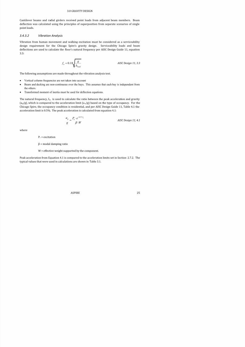
3.4.3.2 Vibration Analysis
Vibration from human movement and walking excitation must be considered as a serviceability
design requirement for the Chicago Spire’s gravity design. Serviceability loads and beam
deflections are used to calculate the floor’s natural frequency per AISC Design Guide 11, equation
3.3:
0.18n
total
g f
AISC Design 11, 3.3
The following assumptions are made throughout the vibration analysis test.
Vertical column frequencies are not taken into account
Beam and decking are non-continuous over the bays. This assumes that each bay is independent fromthe others.
Transformed moment of inertia must be used for deflection equations.
The natural frequency, f n, is used to calculate the ratio between the peak acceleration and gravity
(ap/g), which is compared to the acceleration limit (ao/g) based on the type of occupancy. For the
Chicago Spire, the occupancy condition is residential, and per AISC Design Guide 11, Table 4.1 the
acceleration limit is 0.5%. The peak acceleration is calculated from equation 4.1:
0.35 n f p o
a P e
g W
AISC Design 11, 4.1
where
Po = excitation
β = modal damping ratio
W = effective weight supported by the component.
Peak acceleration from Equation 4 1 is compared to the acceleration limits set in Section 2 7 2 The
3.0 GRAVITY DESIGN

7/17/2019 Structural Design Project of Super Tall Building Chicago Spire
http://slidepdf.com/reader/full/structural-design-project-of-super-tall-building-chicago-spire 42/474
Table 3.1: Typical Values for Vibrational Analysis Calculations
Residential Mechanical Lobby Units
Number of joists framing into
girders
2 3 3
Thickness of corrugation 1.5 2 1.5 in
Weight of decking 1.78 3.29 1.78 psf
Theoretical volume of concrete 0.253 0.292 0.253 ft3/ft
2
Total Load 60 65 60 psfFrom AISC Design Guide 11, Table 4.1
β 0.2 0.2 0.2
Po 65 65 65 lbs
When a member or bay is subjected to excitation at its natural frequency, f n, the beam will reach its
maximum vibrational displacements. The natural frequencies of members depend on their stiffness
and mass. Members analyzed individually showed a natural frequency in the range of 3 Hz to 22 Hz;
however, when analyzed as a combined system yielded natural frequencies between 3 Hz and 10
Hz. The peak acceleration for the Chicago Spire was found to be between 0.040% and 0.246%. See
Table 3.2 for the full range of values.
Table 3.2: Summary of Estimated Vibrations
Type Bank ap/g ao/g
Residential 1 0.332% 0.50%
Mechanical 1 0.099% 0.50%
Lobby 1 0.199% 0.50%
Residential 2 0.246% 0.50%
Mechanical 2 0.040% 0.50%
Lobby 2 0.086% 0.50%
Residential 3 0.194% 0.50%
Mechanical 3 0.043% 0.50%
Lobby 3 0.073% 0.50%
Residential -1 4 0.146% 0.50%
R id i l 2 4 0 130% 0 50%
3.0 GRAVITY DESIGN

7/17/2019 Structural Design Project of Super Tall Building Chicago Spire
http://slidepdf.com/reader/full/structural-design-project-of-super-tall-building-chicago-spire 43/474
3.5 Façade Beam Design
The beams running along the slab edge support the façade and design loads from Table 2.2. These
beams were designed as hollow structural section (HSS) to account for large, curved spans. Section
geometry of HSS beams allows for increased constructability and resistance to torsion. Blodgett’s
Design of Welded Structures was used to calculate end torsion of the curved beams. The following
assumptions were made throughout the HSS beam design process.
Tributary area was calculated from the Revit model (Figure 3.9)
Other than torsion at the beam ends and angular twist, all other calculations for bending moment
and shear capacity assume that the beam is straight.
Figure 3.9: Tributary Areas for the HSS Beam
A preliminary section was chosen for all perimeter façade beams. Table 3.3 summarizes this
design.
Table 3.3: HSS Beam Design Summary
3.0 GRAVITY DESIGN

7/17/2019 Structural Design Project of Super Tall Building Chicago Spire
http://slidepdf.com/reader/full/structural-design-project-of-super-tall-building-chicago-spire 44/474
3.6 Column Design
Vertical columns and slanted transfer columns were selected given the gravity design load
combination in Section 3.1.2. Axial loads for column design were calculated using a column load
takedown. The structure was split fourteen subsections for the column schedule. Initial composite
and steel shapes were chosen for these locations. These sizes serve as a baseline for structural
software modeling and energy optimization. The column sizes are expected to change multiple
times once lateral forces are analyzed for strength and serviceability.
All vertical concrete has a 28-day compressive strength of 14,000 psi. High density concrete,
ρc=160 pcf, is also used in all composite columns and the concrete core wall. Design tools for axialforces, vertical columns sizing and transfer columns sizing can be found in Calculation 3.4.
3.6.1 Column Load Takedown
A column load takedown tool calculated axial forces given factored design loads and respective
tributary areas. Axial forces were calculated for the exterior columns and the core bearing walls.
Beam columns transfer eccentric loads at mechanical floors due to the chosen column grid
summarized in Table 2.1. Two gravity load paths, shown in Figure 3.10, allow for the design of four
types of columns. Column 1 extends the entire height of building while Column 2 of Banks 3 and 4
is transferred to two columns, 3a and 3b, for Banks 1 and 2. Figure 3.11 and Figure 3.12 display the
typical column grid for Bank 1 and Bank 3, respectively. For constructability purposes the column
details should be similar in each subsection.
3.0 GRAVITY DESIGN

7/17/2019 Structural Design Project of Super Tall Building Chicago Spire
http://slidepdf.com/reader/full/structural-design-project-of-super-tall-building-chicago-spire 45/474
Figure 3.10: Steel Column Load Paths
Column 1
Column 2
3.0 GRAVITY DESIGN

7/17/2019 Structural Design Project of Super Tall Building Chicago Spire
http://slidepdf.com/reader/full/structural-design-project-of-super-tall-building-chicago-spire 46/474
Figure 3.12: Bank 1 Steel Column Layout
Axial loads for the core were also found using the column load takedown. The core was notoriginally designed for solely gravity forces. The core loads from the column load takedown were
utilized in the three dimensional finite element model as nodal forces.
The core is divided into four shear walls, an East-West pair, and a North-South pair. The shear
walls act as coupling units through the reinforced concrete link beams and slab. The column load
takedown calculated axial forces for individual shear walls. Elevator shaft openings throughout the
tower limit the core wall shapes. Generic core wall geometry was simplified to the cross section
shown in Figure 3.13. In Bank 4 the reduced shaft opening space and the tapering of exterior
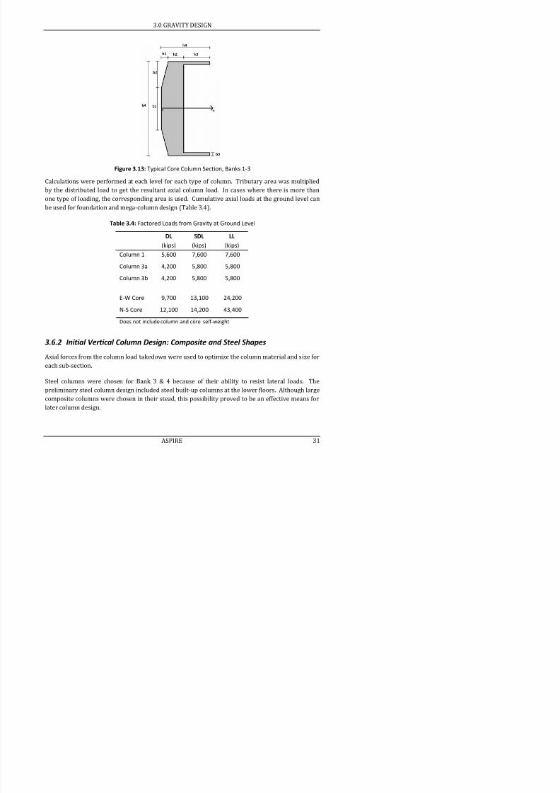
columns leads to an exception to the typical core geometry.
Column 1
Column 3a/3b
3.0 GRAVITY DESIGN
7/17/2019 Structural Design Project of Super Tall Building Chicago Spire
http://slidepdf.com/reader/full/structural-design-project-of-super-tall-building-chicago-spire 47/474
Figure 3.13: Typical Core Column Section, Banks 1-3
Calculations were performed at each level for each type of column. Tributary area was multiplied
by the distributed load to get the resultant axial column load. In cases where there is more than
one type of loading, the corresponding area is used. Cumulative axial loads at the ground level can
be used for foundation and mega-column design (Table 3.4).
Table 3.4: Factored Loads from Gravity at Ground Level
DL SDL LL
(kips) (kips) (kips)
Column 1 5,600 7,600 7,600
Column 3a 4,200 5,800 5,800
Column 3b 4,200 5,800 5,800
E-W Core 9,700 13,100 24,200
N-S Core 12,100 14,200 43,400
Does not include column and core self-weight
3.6.2 Initial Vertical Column Design: Composite and Steel Shapes
Axial forces from the column load takedown were used to optimize the column material and size for
3.0 GRAVITY DESIGN

7/17/2019 Structural Design Project of Super Tall Building Chicago Spire
http://slidepdf.com/reader/full/structural-design-project-of-super-tall-building-chicago-spire 48/474
The initial column sections of the Chicago Spire were optimized for strength, economy, and
architectural constraints. Composite columns were designed following AISC Chapters I, G1 and G2.
Steel columns were designed using AISC Chapters H1. Column behavior from lateral load
combinations was not considered for this deliverable. Figure 3.14 shows a typical composite
column section with a W-shape and reinforcement encased in concrete.
Figure 3.14: Composite Column Section
Appendix 9.9 summarizes the initial column sizes for each subsection of the Spire.
3.6.3
Transfer Column Design
At mechanical floors, angled beam-columns transfer gravity loads from one bank to another. As the
height of the structure increases, the building tapers and radial column grids reduce in diameter.
Figure 3.15 shows the different transfer column configurations for each bank. The columns were
designed in accordance with AISC Chapter H1 because they are subject to both axial and flexural
forces.
Using the loads from the column load takedown, nominal moments and compressive strengths
were calculated. The columns were designed to satisfy flexural and axial limit states. Upon
preliminary analysis, it was discovered that typical W-shapes were not sufficient for the combined
loading criteria. Built up columns or W-shapes with cover plates are needed to fully satisfy the
design loads.
4.0 LATERAL LOAD RESISTING SYSTEM DESIGN

7/17/2019 Structural Design Project of Super Tall Building Chicago Spire
http://slidepdf.com/reader/full/structural-design-project-of-super-tall-building-chicago-spire 49/474
4.0 Lateral Load Resisting System Design
ASPIRE conducted a three phase lateral system design for the Chicago Spire. First, a preliminary
lateral analysis modeled the building as a cantilever tube representing the reinforced concrete core.
Each bank was assigned an initial wall thickness and inner radius to optimize the critical tensile and
compressive stresses at the base of the bank. The preliminary core thicknesses were very large and
unfeasible for construction and design, so additional investigation was necessary.
This deliverable incorporates the columns into the lateral design and assesses the need for
additional lateral systems. Outriggers and belt trusses have been added to create an integrated
system. The core and the columns act together to resist lateral forces and torsional moments fromwind and seismic load combinations. A three-dimensional model was created with MIDAS Gen to
run load cases in static and dynamic analyses. Core walls, outriggers, and belt trusses were sized
using sensitivity analyses to meet serviceability requirements defined in Section 2.7.
Critical moments and axial forces, taken from the finite element model, showed the preliminary
sizing from the gravity design to be inadequate. Ultimately, column steel area was increased to
improve the structure’s stiffness. This was critical to lateral deflection and gravity load shedding at
outrigger levels.
4.0 LATERAL LOAD RESISTING SYSTEM DESIGN

7/17/2019 Structural Design Project of Super Tall Building Chicago Spire
http://slidepdf.com/reader/full/structural-design-project-of-super-tall-building-chicago-spire 50/474
4.1 Structural System Overview
The overall structural systems are critical to the lateral design of the Chicago Spire. The Chicago
Spire includes a reinforced concrete core surrounded by radial exterior columns. In three isolated
mechanical sections, two-story trusses span between the radial columns and the core, acting as
outriggers that tie the movements and rotations of the columns to the core. Outriggers are also
effective in shedding gravity loads from the columns to the concrete core. Belt trusses also
surround these levels to tie the columns together into a cohesive unit.
While the gravity system was designed for code defined loads and calculated tributary areas, lateral
forces are both unpredictable and significant. Statistical analyses are typically performed todetermine the critical wind and seismic lateral forces for both design and serviceability conditions.
Wind tunnel loads and torsional moments were provided by RWDI and provide an accurate
estimate of 100-year MRI forces on the Chicago Spire. ASCE 7 design procedures for wind loads
produce extremely conservative results for tall, slender buildings.
The core of the building is primarily designed to be a stiff lateral load-resisting system. Although
size and openings are constrained by architectural specifications, the core still needs to resist
critical wind and seismic forces. These forces develop an overturning moment in the core that
induces tensile stresses on the windward side of the core and compression stresses on the leeward
side. The moment induced in the core near the top of the building is fairly negligible, necessitating
a core of only a few feet thick. However, near the base, this moment can be significant enough to
control the overall core design. Concrete has a strong resistance to compressive stresses, yet is
weak in tension. The core is heavily reinforced with flexural reinforcement to resist the tension
stresses. Additionally, the outrigger and belt truss system helps reduce the overturning moment,
thereby reducing the tensile stresses. Figure 4.1 shows the locations of the belt truss and outrigger
system at mechanical floors.
4.0 LATERAL LOAD RESISTING SYSTEM DESIGN

7/17/2019 Structural Design Project of Super Tall Building Chicago Spire
http://slidepdf.com/reader/full/structural-design-project-of-super-tall-building-chicago-spire 51/474
Figure 4.1: 3D model of Outrigger and Belt Truss Locations
Belt Truss
Outrigger
4.0 LATERAL LOAD RESISTING SYSTEM DESIGN
4 2 P li i C W ll D i

7/17/2019 Structural Design Project of Super Tall Building Chicago Spire
http://slidepdf.com/reader/full/structural-design-project-of-super-tall-building-chicago-spire 52/474
4.2 Preliminary Core Wall Design
Hand calculations were completed to estimate initial core wall thicknesses and reinforcement limits
based on the compressive strength of concrete and the modulus of rupture. Wind tunnel testing
provided by RWDI proved to be more accurate than ASCE design loads. All exterior framing,
foundations, slabs, and columns are ignored in these calculations. The Chicago Spire’s core is
assumed to act as a cantilever resisting lateral forces from seismic activity or wind and axial forces
from self-weight, dead loads, and live loads. Calculations 4.2 and 4.3 summarize the engineering
calculations used to develop baseline core wall thicknesses when considering both a system with
and without outriggers.
4.2.1
Core Wall Design Loads
A combination of wind tunnel data, ASCE 7-05 and ASCE 7-10 were used to find forces, stresses, and
moments at each floor.
ASCE 7-10 used for seismic load calculation
ASCE 7-05 2.3.2 basic load combinations used for wind strength design
ASCE 7-05 CC.1 basic load combinations used for wind serviceability verification
RWDI 100 year MRI Wind Tunnel Testing Information Used for wind serviceability load
calculation (Appendix 9.2).
The loads at the bottom floor of each bank were used to calculate controlling tensile and
compressive stresses. The loads used in the calculations are in Table 4.1 below. The floor at the
base of each bank was assessed for a conservative approach.
Table 4.1: Critical Core Wall Unfactored Design Loads
Core Gravity Loads Lateral Moments
Total Dead
Load
(SDL + DL)
Total
Live Load
Core Self Weight
Above Floor
ASCE 7-10
Seismic RWDI Wind Tunnel
Bank Floor kips kips kips k-ft k-ft
1 1 81,958 84,464 594,387 8.82E6 9.41E62 40 56,024 59,908 282,275 5.49E6 5.16E6
3 74 33,366 37,076 141,506 2.86E6 2.42E6
4a 111 15,356 21,238 38,397 8.02E5 5.70E5
4b 130 6,810 13 496 15 825 2 25E5 1 20E5
4.0 LATERAL LOAD RESISTING SYSTEM DESIGN
The loads in Table 4 1 have been determined from various design tools:

7/17/2019 Structural Design Project of Super Tall Building Chicago Spire
http://slidepdf.com/reader/full/structural-design-project-of-super-tall-building-chicago-spire 53/474
The loads in Table 4.1 have been determined from various design tools:
Dead load, superimposed dead load, and live load are from a column load takedown created
for the gravity design deliverable. The column load takedown calculated loads for each corewall section. These values were scaled to represent the total unfactored loading on the
assumed tube for each floor.
Seismic moments were calculated as the sum of all moment arms from lateral seismic
forces, Fx.
Wind moments were calculated as the sum of all moment from critical lateral wind forces.Recommended wind load combinations were considered. A critical resultant force from the
effects of Fx and Fy at each floor was used for the preliminary design moments. Wind
moment calculations ignore torsional moments provided by RWDI testing.
4.2.2
Core Wall Design
The concrete cantilevered tube was designed to resist the previously calculated gravity and lateral
loads. The inner radius and core wall thickness were adjusted at each bank to account for the
varying loads throughout the building. The strength design load combinations from Section 2.6.
The compressive stress block due to the gravity load was combined with the lateral stress diagram
to calculate net compressive and tensile stresses at the extreme outer fiber of the core. Shear forces
and moments were calculated from the distributed seismic and wind forces. Figure 4.2 displays a
sample combination of gravity and lateral induced stresses.
4.0 LATERAL LOAD RESISTING SYSTEM DESIGN

7/17/2019 Structural Design Project of Super Tall Building Chicago Spire
http://slidepdf.com/reader/full/structural-design-project-of-super-tall-building-chicago-spire 54/474
The following equations were used:
( , )
gravity lateral comp tens
P M c
A I
where
c = distance from center to extreme outer fiber
I = second moment of area
A = section area of concrete tube
Pgravity = critical gravity load
Mlateral = critical moment from lateral forces
The controlling compressive and tensile stresses from the load combinations were compared to
allowable stresses found in ACI 318. Table 4.2 summarizes the design comparison between the
controlling stresses from the six load combinations to the allowable stress values. The
reinforcement is designed assuming the steel yields first, allowing Φ = 0.90.
Table 4.2: Controlling Stresses for Core Wall Design
1 2 3 4a 4bNet Compression = 6.468 4.647 3.552 2.066 1.050 ksi
Net Tension = -3.610 -2.989 -2.698 -1.463 -0.465 ksi
Allowable Compression = 0.55*φ * f'c = 6.93 ksi ACI 318 (14.5.2)
Allowable Tension = 7.5 * (f'c).5
= -0.887 ksi Φ = 0.90
The equations for net compression and tension are dependent on the cross sectional area of the
core and the moment of inertia. The core thickness and inner radii were adjusted to meet the
allowable compression constraint, as shown in the next section. The grey highlighted cells in Table
4.2 exceed the modulus of rupture; however, preliminary analysis ignores concrete reinforcement
4.0 LATERAL LOAD RESISTING SYSTEM DESIGN

7/17/2019 Structural Design Project of Super Tall Building Chicago Spire
http://slidepdf.com/reader/full/structural-design-project-of-super-tall-building-chicago-spire 55/474
Figure 4.3: Distributed Lateral Load for Core Wall
Bernoulli’s equation was used to calculate the maximum tip deflection from the uniform loads
calculated from the RWDI forces.
The maximum global tip deflection was calculated to be 10 ft (Calculation 4.1). This fails the global
serviceability requirement; however, this does not account for the contribution of outriggers orexterior columns.
4.2.4 Reinforcement Requirements
y w
24 E Ix
4
c1
6x
3
c2
2x
2 c3 x c4

7/17/2019 Structural Design Project of Super Tall Building Chicago Spire
http://slidepdf.com/reader/full/structural-design-project-of-super-tall-building-chicago-spire 56/474
4.0 LATERAL LOAD RESISTING SYSTEM DESIGN
4.3 Auxiliary Lateral Systems

7/17/2019 Structural Design Project of Super Tall Building Chicago Spire
http://slidepdf.com/reader/full/structural-design-project-of-super-tall-building-chicago-spire 57/474
4.3 Auxiliary Lateral Systems
Tall building design is typically controlled by seismic or wind forces. Reinforced concrete core
walls and columns cannot resist the overturning moment and base shear without an additional
lateral system. Additional lateral systems were employed to create a cohesive, stiff structure to
optimize design and meet serviceability requirements. Lateral systems require large beam
members or truss systems with architectural constraints often controlling their location and design.
4.3.1 Need for Auxiliary System in the Chicago Spire
The core thicknesses determined in the Section 4.2 calculations are excessive and unfeasible forconstruction. In order to reduce core wall thicknesses, outriggers will be constructed as large
transfer girders on the mechanical floors of Banks 1-3. These will span two levels from the exterior
columns to the concrete core wall.
Figure 4.4: Outriggers Spanning Two Mechanical Floors
Preliminary calculations show that outriggers will increase the moment of inertia and stiffness ofthe structure. This decreases the net stresses at each bank. The concrete core wall thicknesses are
reduced to optimize the compressive strength requirements. These final thicknesses are used as
base points for the MIDAS Gen structural model. To determine the stiffness of the perimeter
column system it was necessary to first determine the effective moment of inertia of the circle of
4.0 LATERAL LOAD RESISTING SYSTEM DESIGN
The effective moment of inertia was determined by drawing a centerline through the middle of the

7/17/2019 Structural Design Project of Super Tall Building Chicago Spire
http://slidepdf.com/reader/full/structural-design-project-of-super-tall-building-chicago-spire 58/474
building and calculating the distance of each individual column from that centerline. The moment
of inertia for an object not centered on the centroid is:
I CL = I object + Ad 2
where
Iobject = moment of inertia of column
A = section area of column
d = distance from centroid to center of object
The moment of inertia of the columns, Iobject , is insignificant compared to Ad2 and can be neglected.
I CL ≈ Ad 2
The following assumptions were made for the core wall calculations utilizing outriggers and
exterior columns.
Steel and composite column section properties are from initial gravity design.
Increase in concrete volume and area from columns considered negligible for stresses from
gravity loads.
Itotal = Icore + 0.7*Icolumns where 0.7 is an assumed factor provided that outriggers and belt trusses
are not infinitely stiff.
Calculations use smallest column size per section for a conservative approach.
Table 4.5 highlights the effective Modulus of Elasticity, moment of inertia and stiffness of each
column section throughout the structure.
4.0 LATERAL LOAD RESISTING SYSTEM DESIGN
Table 4.5: Summary of Column Properties for each Column Section

7/17/2019 Structural Design Project of Super Tall Building Chicago Spire
http://slidepdf.com/reader/full/structural-design-project-of-super-tall-building-chicago-spire 59/474
Bank Level # Columns Column Radius (ft) Eeff (ksi) Ieff (ft4) EI (kip-in2)
4 145 14 53.5 29000 4050 2.44E+124 134 14 53.5 29000 4050 2.44E+12
4 123 14 53.5 29000 7905 4.75E+12
4 113 14 53.5 29000 12721 7.65E+12
3 100 14 61 29000 22613 1.36E+13
3 87 14 61 29000 29306 1.76E+13
3 75 14 61 29000 35457 2.13E+13
2 64 21 68.5 8873 197001 3.62E+132 52 21 68.5 10953 197001 4.47E+13
2 41 21 68.5 12481 197001 5.10E+13
1 29 21 75.5 10458 373939 8.11E+13
1 17 21 75.5 11700 373939 9.07E+13
1 5 21 75.5 9390 538473 1.05E+14
1 Lobby 7 75.5 9390 538473 1.05E+14
The moment of inertias from Table 4.5 were combined with the core wall moment of inertia to
determine new compressive and tensile forces following a similar procedure described in Section
4.2.2. Table 4.6 summarizes the reduction in tensile and compressive forces at each bank. Despite
minimal effects to the top of the Spire, outriggers make a significant contribution in Banks 1 and 2.
Table 4.6: Stress Reduction in each Bank from Outriggers
% Reduction in Each Bank: 1 2 3 4a 4b
In Applied Compression 17% 10% 3% 2% 1%
In Applied Tension 30% 16% 6% 5% 3%
The same loads and procedure described in Section 4.2.5 were used to calculate new core wall
thicknesses that incorporate the outriggers. Table 4.7 summarizes the preliminary calculations for
core wall thicknesses incorporating auxiliary lateral systems.
Table 4.7: Summary of Core Wall Thicknesses with Outriggers and Columns
B k 1 2 3 4 1 4 2
4.0 LATERAL LOAD RESISTING SYSTEM DESIGN
The need for belt trusses and outriggers was assessed qualitatively and these members were not
f ll d d h AS G f d l h b ll b 1 30

7/17/2019 Structural Design Project of Super Tall Building Chicago Spire
http://slidepdf.com/reader/full/structural-design-project-of-super-tall-building-chicago-spire 60/474
specifically designed. For the MIDAS Gen software model, the members will be W14x730 to
increase structural stiffness.
4.3.2 Relative Stiffness of Structural Systems
A basic analysis of the stiffness of the core and column systems was conducted to ensure uniform
performance under applied loads. In order to perform as a cohesive system, the stiffness of the
reinforced concrete core needs to be similar to that of the outrigger and column system. The stiffer
system will take a proportionately larger amount of the stresses than the other system. Therefore,
if the column and outrigger system is stiffer than the core, the full capacity of the core would not be
used and columns could potentially be overstressed to the point of failure.
The relative stiffness of the core and column system will be compared by using the product of the
elastic modulus and the moment of inertia.
Each bank has different section properties, so the core was analyzed in five different segments
corresponding to Banks 1, 2, 3, 4.1, and 4.2. The values for each bank are tabulated in Table 4.8
below.
Table 4.8: System Stiffness Summary
Bank
Core Stiffness,
EI (kip-in2)
Column Stiffness,
EI (kip-in2)
Sum
(kip-in2)
Sum-to-Core
% Increase
0.7-Reduced
Sum (kip-in2)
0.7-Reduced
Sum-to-Core
% Increase
4.2 3.48E+13 2.44E+12 3.72E+13 7.00% 3.65E+13 4.90%
4.1 3.48E+13 7.65E+12 4.24E+13 21.99% 4.01E+13 15.40%3 1.14E+14 2.13E+13 1.35E+14 18.73% 1.29E+14 13.11%
2 1.95E+14 5.10E+13 2.46E+14 26.15% 2.31E+14 18.30%
1 2.65E+14 1.05E+14 3.70E+14 39.58% 3.38E+14 27.71%
The two systems, although separate, will be connected via outriggers spanning from the core to the
columns on the mechanical levels. To determine the effect of the combined systems, each system
can be idealized as a spring with a stiffness equivalent to that of the actual system. The two
“springs” will be connected in parallel by the outriggers, and by simple elastic behavior theory, the
system will have an effective stiffness of the sum of the two springs’ individual stiffness. However,
this value assumes a perfectly rigid connection by the outriggers between the core and the columns.
4.0 LATERAL LOAD RESISTING SYSTEM DESIGN
4.4 Finite Element Model

7/17/2019 Structural Design Project of Super Tall Building Chicago Spire
http://slidepdf.com/reader/full/structural-design-project-of-super-tall-building-chicago-spire 61/474
A detailed structural analysis of the Chicago Spire was conducted using MIDAS Gen. All material
properties and baseline element shapes were taken from initial lateral and gravity design. Verticalmembers, outriggers and belt trusses, and core wall thicknesses were resized throughout the
iterative modeling process based on element forces and moments, and serviceability requirements.
4.4.1 Initial Modeling Process
A three-dimensional model of the Chicago Spire was created in MIDAS Gen to model the behavior of
the building in response to dynamic and static forces. The following modeling procedures andassumptions were made for the initial model.
The model spans from the lobby at ground elevation to the top of level 144.
The tuned mass damper and hypothetical mechanical floors at the Spire’s peak are not
considered. All below-grade elements are not modeled.
The mega-columns and core wall at the ground elevation are fixed to the ground.
Table 4.9 summarizes the initial elements properties modeled in MIDAS.
Table 4.9: Initial MIDAS Model Element Properties
Structural Member Element Type Material Property
Core Wall Plate, thick with drilling DOF RC, C14000
Column B1 B2 B3 General Beam SRC, C14000, A992
Column B4 General Beam S, A992
Transferring Column General Beam S, A992
Radial Beam General Beam SRC, C4000, A992
Column Beam General Beam SRC, C4000, A992
Link Beam General Beam RC, C4000
Outrigger and Belt Truss Truss SRC, C4000, A992
(S)RC: (Steel) Reinforced Concrete
CXXXX: Concrete and f’c (psi)
MIDAS G li i i f d i l f’ 10 000 i h h d l f
4.0 LATERAL LOAD RESISTING SYSTEM DESIGN
Core walls are modeled as thick plate element with drilling DOF, since out-of-plane shear is
not considered negligible

7/17/2019 Structural Design Project of Super Tall Building Chicago Spire
http://slidepdf.com/reader/full/structural-design-project-of-super-tall-building-chicago-spire 62/474
not considered negligible.
Core walls contain openings as shown in structural and architectural drawings.
Composite beams were simplified to W-Shape Steel Reinforced Concrete (SRC) in crosssection properties. The widths chosen in these SRC beams are based on the effective widths
of the composite beam from the gravity design.
All structural elements have been applied fixed-fixed end-releases. Cantilevers and angled
floor girders outside of the exterior column grid were not considered.
4.4.2 Loading and Load Combinations
All design loads were applied as nodal point forces. The column load takedown from Section 3.6.1
and provided wind tunnel information were used to calculate gravity and lateral forces. The
following procedures summarize the applied loads for design and serviceability criteria.
The wind forces from the wind tunnel testing are used directly for strength design. The
wind forces and torsional moments from Appendix 9.2 were applied to each level along the
z-axis.
The wind tunnel recommended combinations from Appendix 9.2 were used as a sub level ofload combinations.
A reduction factor of 0.83 (1/1.2) was applied to the RWDI wind loads to reduce the 100
year MRI loads to a 50 year MRI loads for serviceability design.
Unfactored dead loads and live loads from the column load takedown were applied to nodes
at column ends. Superimposed dead load and dead load combined for total dead load.
Appendix 9.10 summarizes the nodal gravity forces used in MIDAS Gen.
The total unfactored dead load and live load for the core was split equally into nodal forces
to the nodes connecting the radial girders to the core walls or link beams. Appendix 9.10summarizes the nodal gravity forces used in MIDAS Gen
MIDAS Gen calculates material self-weight in the analysis, thus no self-weight is considered
in applied dead loads.
The load combinations from Section 2.6 are used for both strength and serviceability.
4.4.3
Iteration and Element Redesign
Column Validation
Original MIDAS Gen sizes for vertical columns, transfer columns, and mega-columns were from the
4.0 LATERAL LOAD RESISTING SYSTEM DESIGN

7/17/2019 Structural Design Project of Super Tall Building Chicago Spire
http://slidepdf.com/reader/full/structural-design-project-of-super-tall-building-chicago-spire 63/474
Figure 4.5: Compression Block and Steel Strain from Weak Axis Bending
The forces and moments for all load combinations were plotted on the interaction diagram. Steel
shapes, concrete dimensions, and reinforcement specifications were adjusted to optimize the
column design. This process was repeated several times with new column sizes recycled into
MIDAS Gen model and new forces and moments plotted on the interaction diagrams. Appendix
9.11 shows the composite and steel column sizes after several iterations of column validation.
Exterior Steel Stiffness
The new column sizes showed severe discontinuity under gravity forces due to the core and
outriggers being significantly stiffer than the columns. The columns were showing tension forces as
seen in Figure 4.6.
Several sensitivity analyses were used to troubleshoot the model and reduce the load sheddingshown in Figure 4.6 and the excessive deflection. The analyses are summarized in Appendix 9.11.
4.0 LATERAL LOAD RESISTING SYSTEM DESIGN

7/17/2019 Structural Design Project of Super Tall Building Chicago Spire
http://slidepdf.com/reader/full/structural-design-project-of-super-tall-building-chicago-spire 64/474
Figure 4.6: Initial Discontinuity Check under Gravity Loads
Final Design
The final design of the MIDAS Gen model saw several improvements from the original model. The
improvements resulted in acceptable drift under serviceability loads and reasonable load shedding
under gravity loads. The following changes helped reach these goals. Table 4.10 shows the final
model element properties.
Increased steel area in exterior column grid.
Reduced thickness of core walls.
Reduced size of belt truss members.
Table 4.10: Final MIDAS Model Element Properties
Core WallThickness by
Bank (ft) Belt
Truss Outrigger
Vertical Column Size by Bank
1 2 3 4 1 2 3 4
7 4 3 2 W14 53 W14 730 BU1 BU1 BU2 BU2
4.0 LATERAL LOAD RESISTING SYSTEM DESIGN

7/17/2019 Structural Design Project of Super Tall Building Chicago Spire
http://slidepdf.com/reader/full/structural-design-project-of-super-tall-building-chicago-spire 65/474
Figure 4.7: a) BU1 and b) BU2
The final MIDAS Gen model included the built-ups in Figure 4.7 encased in concrete. However, the
concrete was ultimately deemed unnecessary negligible in composite action given the high steel
area. The final design will consist of solely, steel exterior columns.
4.4.4 Results Comparison
The final design was a significant improvement from the original MIDAS Gen design based on
gravity design and preliminary lateral studies. Although Figure 4.8 shows an increase in ultimatecompressive forces, the load shedding at the mechanical floors follows the industry standard of
≈20%. Tension members no longer exist and the overall shape of the compression graph follows
the expected graph of a single column line extending up a building. Table 4.11 shows a sample
comparison of MIDAS results.
4.0 LATERAL LOAD RESISTING SYSTEM DESIGN

7/17/2019 Structural Design Project of Super Tall Building Chicago Spire
http://slidepdf.com/reader/full/structural-design-project-of-super-tall-building-chicago-spire 66/474
Figure 4.8: Discontinuity Test Comparison between Original and Final Design
Table 4.11: Initial and Final MIDAS Results
Initial Final Allowable (400
h)
Base Shear kips 27,500 49,000 N/A
Global Deflection ft 6.71 4.48 5.0
Maximum Inter-story Drift in 0.88 0.56 0.40
4.0 LATERAL LOAD RESISTING SYSTEM DESIGN
The troubleshooting and iteration of the MIDAS model proved to be the most tedious and time
consuming aspect of the Chicago Spire structural design. Ultimately the model produced acceptable

7/17/2019 Structural Design Project of Super Tall Building Chicago Spire
http://slidepdf.com/reader/full/structural-design-project-of-super-tall-building-chicago-spire 67/474
global deflection and forces for connection, foundation, and core wall design.
4.0 LATERAL LOAD RESISTING SYSTEM DESIGN
4.5 Core Wall Reinforcement Design

7/17/2019 Structural Design Project of Super Tall Building Chicago Spire
http://slidepdf.com/reader/full/structural-design-project-of-super-tall-building-chicago-spire 68/474
Core walls were designed using the final MIDAS Gen model thicknesses as reinforced concrete
shear walls. The shear and flexural reinforcement was designed using loads, shears and momentspulled from the MIDAS Gen model. Reinforcement was designed separately for the North-South
and East-West core walls on Bank 1, Bank 2 and Bank 3, and for the sole coupled core wall of Bank
4. The horizontal shear capacity was calculated using MIDAS Gen section areas and loads, and
spacing and reinforcement were selected based on the required steel ratio. These values were
subsequently applied to the core’s actual shape. Minimal vertical shear exists, thus the vertical
reinforcing was designed based on required steel ratio.
For the first three banks, the North-South (NS) and East-West (EW) cores worked together to resist
flexural moment, and the moment capacity of the coupled cores was calculated using the vertical
reinforcement. For Bank 4, the cores worked together to resist moment along their weak axis, but
resisted moment individually across their strong axis. For this latter moment, the moment-axial
force pairs were plotted on a column interaction diagram produced using vertical reinforcing steel.
For all banks, the vertical reinforcing was sufficient to resist moment.
The following assumptions were used to design of the core reinforcement.
MIDAS Gen core section areas were sufficiently similar in size and shear capacity to actual core
size and shear capacity.
Core walls were designed for critical loads at the base of each bank.
Reinforcement details could be designed based on a sub-area of a concrete gross area, and then
applied to a different area of concrete, as long as steel ratios are kept constant.
The link beams allow the core walls in a given bank to act as a single beam. Ties will be sufficient for any given reinforcement configuration.
Core wall section areas are conservative to simplify design procedure. If there is sufficient area
outside of these approximations so as to exceed the spacing of the reinforcement, reinforcement
will be extended into that area.
Appendix 9.13 summarizes the reinforcement spacing and sizes for each bank. Calculation 4.5
shows the reinforcement design calculations.
4.0 LATERAL LOAD RESISTING SYSTEM DESIGN
4.6 Energy Optimization
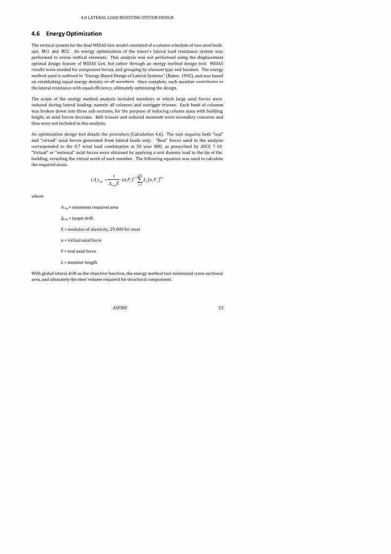
7/17/2019 Structural Design Project of Super Tall Building Chicago Spire
http://slidepdf.com/reader/full/structural-design-project-of-super-tall-building-chicago-spire 69/474
The vertical system for the final MIDAS Gen model consisted of a column schedule of two steel built-
ups, BU1 and BU2. An energy optimization of the tower’s lateral load resistance system wasperformed to resize vertical elements. This analysis was not performed using the displacement
optimal design feature of MIDAS Gen, but rather through an energy method design tool. MIDAS
results were needed for component forces, and grouping by element type and location. The energy
method used is outlined in “Energy-Based Design of Lateral Systems” (Baker, 1992), and was based
on establishing equal energy density on all members. Once complete, each member contributes to
the lateral resistance with equal efficiency, ultimately optimizing the design.
The scope of the energy method analysis included members in which large axial forces were
induced during lateral loading: namely all columns and outrigger trusses. Each bank of columns
was broken down into three sub-sections, for the purpose of reducing column sizes with building
height, as axial forces decrease. Belt trusses and induced moments were secondary concerns and
thus were not included in this analysis.
An optimization design tool details the procedure (Calculation 4.6). The tool requires both “real”
and “virtual” axial forces generated from lateral loads only. “Real” forces used in the analysiscorresponded to the 0.7 wind load combination at 50 year MRI, as prescribed by ASCE 7-10.
“Virtual” or “notional” axial forces were obtained by applying a unit dummy load to the tip of the
building, revealing the virtual work of each member. The following equation was used to calculate
the required areas.
1500.5 0.5
1
1( ) ( ) [ ]i req i i j j j
jreq
A n F L n F
E
where
Areq = minimum required area
Δreq = target drift
E = modulus of elasticity, 29,000 for steel
n = virtual axial force
F = real axial force
4.0 LATERAL LOAD RESISTING SYSTEM DESIGN
Because of the tower’s symmetry and the fact that wind loads can occur in any direction, the critical
required area for each sub-section was applied to all members in that sub-section.

7/17/2019 Structural Design Project of Super Tall Building Chicago Spire
http://slidepdf.com/reader/full/structural-design-project-of-super-tall-building-chicago-spire 70/474
Initial MIDAS Gen modeling targeted a global drift requirement of h/400. The first objective for theenergy optimization was a target drift of 4 ft (h/500). Steel built-up columns were used at the
lower levels and W-sections were used at the higher levels where applicable. The new members
are summarized and compared to baseline values in Table 4.12.
Table 4.12: Optimization Results for Δ = h/500
Baseline
Area
Optimized
Area
Area
Provided
Proposed
SectionType Floors in2 in2 in2
Bank 1
Mega-columns 1-4 848 903 920 BU1
Vertical 5-16 848 800 800 BU2
Vertical 17-28 848 748 768 BU3
Vertical 29-37 848 678 688 BU4
Transfer 38-39 848 587 608 BU5
Outrigger 38-39 215 175 178 W14x605
Bank 2
Vertical 40-52 848 571 576 BU6
Vertical 56-63 848 509 512 BU7
Vertical 64-71 848 500 512 BU7
Transfer 72-73 848 602 608 BU8
Outrigger 72-73 215 151 162 W14x550
Bank 3
Vertical 74-87 688 468 480 BU9
Vertical 88-99 688 335 347 BU10
Vertical 100-108 688 244 250 BU11
Transfer 109-110 688 159 162 W14x550
Outrigger 109-110 215 48 52 W14x176
Bank 4
Slanted 111-122 688 153 162 W14x550
Slanted 123-133 688 135 134 W14x455
Slanted 134-144 688 96 101 W14x342
4.0 LATERAL LOAD RESISTING SYSTEM DESIGN
Table 4.13: Material Savings for Δ = h/500
Volume reduction in steel (ft3) 66800
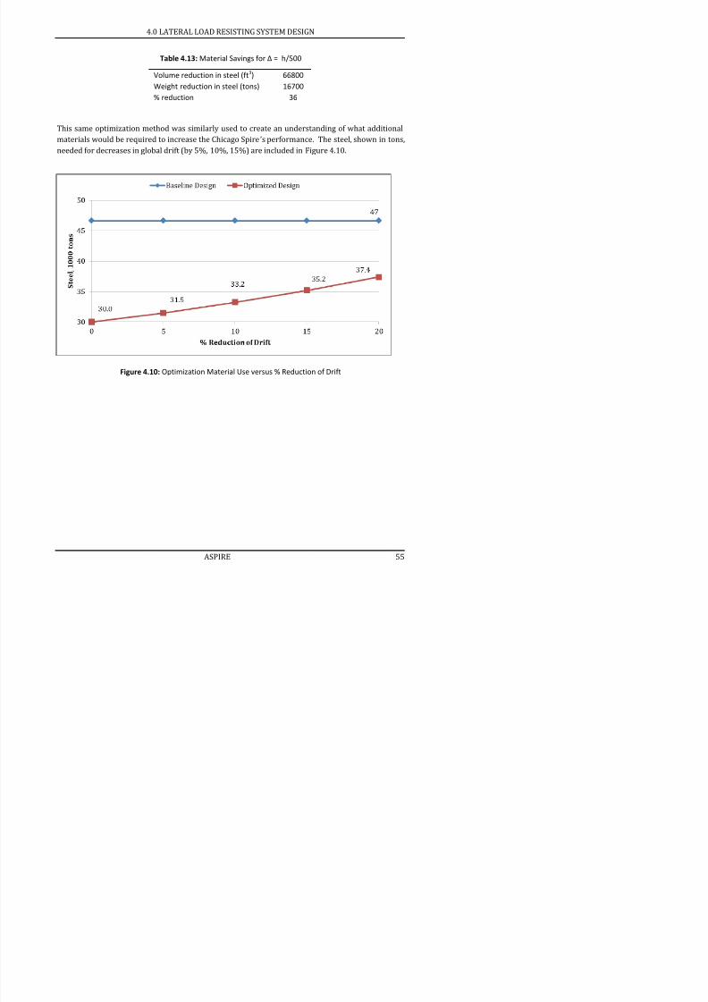
7/17/2019 Structural Design Project of Super Tall Building Chicago Spire
http://slidepdf.com/reader/full/structural-design-project-of-super-tall-building-chicago-spire 71/474
Weight reduction in steel (tons) 16700
% reduction 36
This same optimization method was similarly used to create an understanding of what additional
materials would be required to increase the Chicago Spire’s performance. The steel, shown in tons,
needed for decreases in global drift (by 5%, 10%, 15%) are included in Figure 4.10.
Figure 4.10: Optimization Material Use versus % Reduction of Drift
4.0 LATERAL LOAD RESISTING SYSTEM DESIGN
4.7 Eigenvalue Analysis
A b it ti i l l i f d i th fi l d l i MIDAS G Th

7/17/2019 Structural Design Project of Super Tall Building Chicago Spire
http://slidepdf.com/reader/full/structural-design-project-of-super-tall-building-chicago-spire 72/474
A subspace iteration eigenvalue analysis was performed using the final model in MIDAS Gen. The
first 15 mode shapes were found. Table 4.14 summarizes the natural frequency and period of thefirst fifteen mode shapes. The expected period for mode one of a tall building is n/10, where n = the
number of floors. The eigenvalue analysis results show periods similar to the expected of 15 sec.
Table 4.14: Natural Frequency and Period of first 15 mode shapes
Mode No. Frequency Frequency Period
(rad/sec) (cycle/sec) (sec)
1 0.4098 0.0652 15.33
2 0.4313 0.0686 14.57
3 0.6378 0.1015 9.85
4 1.3013 0.2071 4.83
5 1.4131 0.2249 4.45
6 1.7807 0.2834 3.53
7 2.4401 0.3884 2.57
8 2.9056 0.4624 2.16
9 3.1205 0.4966 2.01
10 3.4213 0.5445 1.84
11 3.9564 0.6297 1.59
12 4.2083 0.6698 1.49
13 5.9338 0.9444 1.06
14 6.4212 1.0220 0.98
15 7.0179 1.1169 0.90
4.0 LATERAL LOAD RESISTING SYSTEM DESIGN
Table 4.15: Modal Mass Participation
Mode No. Translation in X Translation in Y Rotation about Z

7/17/2019 Structural Design Project of Super Tall Building Chicago Spire
http://slidepdf.com/reader/full/structural-design-project-of-super-tall-building-chicago-spire 73/474
MASS(%) SUM(%) MASS(%) SUM(%) MASS(%) SUM(%)
1 0 0 63.05 63.05 0 0
2 62.35 62.35 0 63.05 0 0
3 0 62.35 0 63.06 60.87 60.88
4 0 62.35 17.52 80.58 0 60.88
5 18.37 80.72 0 80.58 0 60.88
6 0 80.72 0 80.58 18.45 79.33
7 0 80.72 5.67 86.24 0 79.33
8 6.58 87.30 0 86.24 0 79.33
9 0 87.30 0 86.24 4.27 83.59
10 0 87.30 3.50 89.74 0 83.59
11 0 87.30 0 89.74 6.01 89.60
12 2.49 89.79 0 89.74 0 89.60
13 0 89.79 1.98 91.72 0 89.60
14 0 89.79 0 91.72 1.70 91.31
15 2.24 92.02 0 91.72 0 91.31
4.0 LATERAL LOAD RESISTING SYSTEM DESIGN
The first two modes of the building are translation modes in orthogonal directions. The third mode
is a torsional mode which primarily acts on the Bank 4. Figure 4.11 shows all three modes from the
MIDAS Gen model. The periods for the first three mode shapes are: 15.33 seconds, 14.57 seconds,

7/17/2019 Structural Design Project of Super Tall Building Chicago Spire
http://slidepdf.com/reader/full/structural-design-project-of-super-tall-building-chicago-spire 74/474
MIDAS Gen model. The periods for the first three mode shapes are: 15.33 seconds, 14.57 seconds,
and 9.85 seconds respectively. The corresponding modal participations are: 63.05%, 62.35%, and60.87%. This indicates that the first three modes are low frequency and the majority of the mass
will be affected at those frequencies. The next three modes show the second mode shape for the
different directions of translation. The sum of the modal participation of the first 15 modes in x-
translation, y-translation, and torsion are all over 90%.
5.0 STEEL AND CONCRETE DETAILING
5.0 Steel and Concrete Detailing
Thousands of connections exist over the height of the building ranging from simple framing

7/17/2019 Structural Design Project of Super Tall Building Chicago Spire
http://slidepdf.com/reader/full/structural-design-project-of-super-tall-building-chicago-spire 75/474
Thousands of connections exist over the height of the building ranging from simple framing
connections to complicated mega-column terminations. ASPIRE identified typical connections thatare prevalent throughout the tower and several classifications of complex connections. A full
structural design would look at all the iterations of each connection to fully understand how each
area load and each bank changes the connection. One occurrence of each connection has been
identified for a full structural design. The same process and design tools can be applied to other,
similar instances.
Element geometry had a significant impact of the type of connections that could be used. All
columns have been finalized as steel members, minimizing the prevalence of composite
connections. The most common composite connection is between radial floor girders and the
concrete core. The use of W-shapes versus built-up sections also affected decisions between bolted
and welded connections.
Ultimately all of the columns were built-up from 4 in thick steel plates which limited column
connections to welds. Connections were standardized for the built-up columns to ensure that
despite column section changes, similar connections can be used. Various failures were checkedper AISC requirements depending on the type of connection.
5.0 STEEL AND CONCRETE DETAILING
5.1 Typical Connections
Five typical steel to steel connections and one typical composite connection will be used in the

7/17/2019 Structural Design Project of Super Tall Building Chicago Spire
http://slidepdf.com/reader/full/structural-design-project-of-super-tall-building-chicago-spire 76/474
yp yp p
Chicago Spire. Radial girders and cantilevers will be connected to the outer ring columns withmoment resisting connections; circumferential girders will be connected to the outer ring column
with single plate connections; the joists will be connected to girders using single angle shear
connections; the HSS beams running along the outside of the building will be connected to the
cantilevers with angles bolted to the cantilever and welded to the HSS section; and column splices
will connect each column with welded plates.
The following typical connection design calculations follow AISC Steel Design Guide and can be
found in Calculation 5.1.
5.1.1 Welded Column Splice
All typical exterior columns are built-up steel shapes and will be spliced using steel plates. The
column splices were designed by welding plates to connect each face of the connecting columns
(Figure 5.1). This was the most economical design because of the similar column sizes throughout
the structure. This type of splice minimizes the footprint of the columns, allowing them to meetarchitectural constraints. Column splices were designed against all load combinations to resist
tension, moment, torsion and shear forces.
5.0 STEEL AND CONCRETE DETAILING
5.1.2 Floor Joist to Girder
The floor joists are connected to the radial girders with single angle, shear connections. At each

7/17/2019 Structural Design Project of Super Tall Building Chicago Spire
http://slidepdf.com/reader/full/structural-design-project-of-super-tall-building-chicago-spire 77/474
connection, two joists connect to opposite sides of the radial girder web. The girder web is not
thick enough to weld at each side, therefore bolts were used (Figure 5.2). This greatly decreases
the amount of field welds required during construction. The initial trial bolt number was calculated
to withstand shear and bearing. Then all failure modes were checked, including bearing and tear
out, shear yielding and rupture, and block shear of the angles and both webs.
Figure 5.2: Elevation of Floor Joist to Girder Connection
5.1.3
Cantilever to HSS Section
The connection between the cantilever beams and HSS Sections is similar to the single angle shear
connection except the angle leg adjacent to the HSS section is welded instead of bolted (Figure 5.3).
Also, an additional weld connects the top flange to the HSS beam to add rigidity to the connection.
Weld
Weld
5.0 STEEL AND CONCRETE DETAILING
5.1.4 Cantilever and Radial Girder to Column
Moment connections to the columns are required for both the radial girders and cantilevers. For
h b fl l ill b ld d l ll d h l fl b d b l
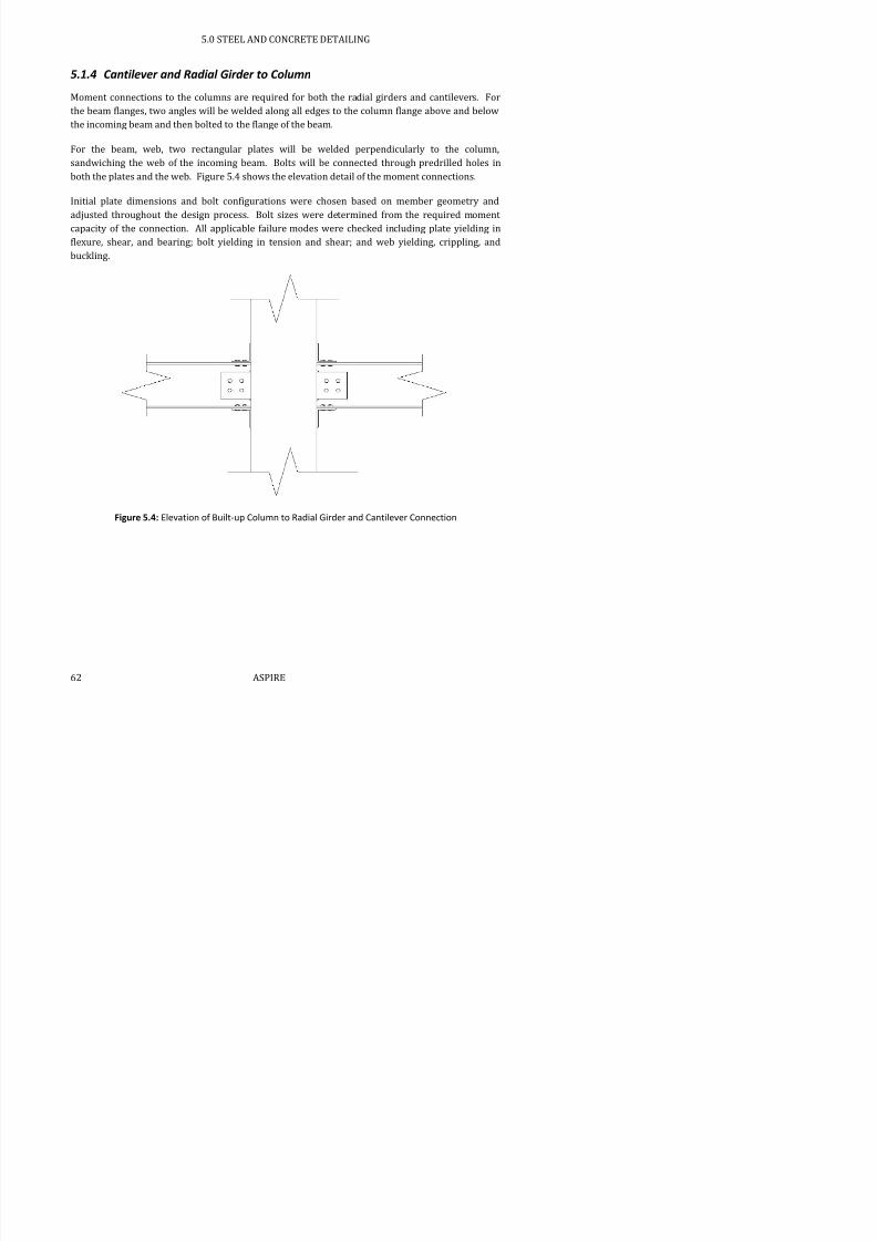
7/17/2019 Structural Design Project of Super Tall Building Chicago Spire
http://slidepdf.com/reader/full/structural-design-project-of-super-tall-building-chicago-spire 78/474
the beam flanges, two angles will be welded along all edges to the column flange above and below
the incoming beam and then bolted to the flange of the beam.
For the beam, web, two rectangular plates will be welded perpendicularly to the column,
sandwiching the web of the incoming beam. Bolts will be connected through predrilled holes in
both the plates and the web. Figure 5.4 shows the elevation detail of the moment connections.
Initial plate dimensions and bolt configurations were chosen based on member geometry and
adjusted throughout the design process. Bolt sizes were determined from the required momentcapacity of the connection. All applicable failure modes were checked including plate yielding in
flexure, shear, and bearing; bolt yielding in tension and shear; and web yielding, crippling, and
buckling.
Figure 5.4: Elevation of Built-up Column to Radial Girder and Cantilever Connection
5.0 STEEL AND CONCRETE DETAILING
5.1.5 Circumferential Girder to Column
The circumferential girders were designed as pinned-pinned and thus could be designed with a
bolted connection One plate is welded perpendicular to the built up exterior column using a fillet

7/17/2019 Structural Design Project of Super Tall Building Chicago Spire
http://slidepdf.com/reader/full/structural-design-project-of-super-tall-building-chicago-spire 79/474
bolted connection. One plate is welded perpendicular to the built-up exterior column using a fillet
weld. The circumferential girder is then placed with its web adjacent to the plate with its flanges
above and below the plate. The plate and column girder are then bolted together. The size and
number of bolts used were determined based on the shear and bearing capacity of the bolts.
The weld of the plate to the column web was also checked. Column web yielding, crippling and
buckling were checked along with block shear, bearing and tear out, shear yielding and shear
rupture of the girder web and plate. Figure 5.5 shows the typical circumferential girder to column
connection.
Figure 5.5: Elevation of Circumferential Girder to Column Plate Connection
Weld
5.0 STEEL AND CONCRETE DETAILING
5.1.6 Radial Girder to Core
Radial girders are connected to the core by a single, shear single plate connection and headed
anchor bolts Headed anchor bolts are welded to a steel anchor plate and cast into the exterior of

7/17/2019 Structural Design Project of Super Tall Building Chicago Spire
http://slidepdf.com/reader/full/structural-design-project-of-super-tall-building-chicago-spire 80/474
anchor bolts. Headed anchor bolts are welded to a steel anchor plate and cast into the exterior of
the concrete core. A single steel plate is welded perpendicular to the base plate using a fillet weld.
The radial girder is then bolted with its web adjacent to the plate, with its flanges above and below
the plate. Figure 5.6 details the composite connection between the radial girder and the core wall.
The single plate bolt details were determined based on the shear and bearing capacity of the bolts.
Plate geometries are based on bolt spacing and beam dimensions. Maximum plate thickness is
determined such that the plate moment strength does not exceed the moment strength of the bolt
group in shear. The capacity of the connection is calculated as the minimum capacity for the limitstates of shear yielding, shear rupture, block shear rupture, shear buckling, and flexural yielding of
the plate and girder weld as well as bearing strength at bolt holes, bolt group shear strength, and
weld capacity.
Figure 5.6: a) Elevation and b) Section of Radial Girder to Core Wall Connection
The headed anchor bolts details were determined based on the tensile and shear capacity of the
steel anchor bolts and the concrete. The capacity of the connection is determined by an interaction
of the design tension strength and design shear strength of the connection. Design tension strength
is calculated as the minimum capacity for the limit states of steel strength of anchors in tension,
concrete breakout strength of anchors in tension, and pullout strength for anchors in tension.
Design shear strength is calculated as the minimum capacity for the limit states of steel strength of
anchors in shear, concrete breakout strength of anchors in shear, and concrete pryout strength of
anchors in shear.
Weld
5.0 STEEL AND CONCRETE DETAILING
5.2 Complex Connections
Several configurations of complex connections are found throughout the Chicago Spire, particularly

7/17/2019 Structural Design Project of Super Tall Building Chicago Spire
http://slidepdf.com/reader/full/structural-design-project-of-super-tall-building-chicago-spire 81/474
at mechanical floors and at the tower’s base. These connections combined simple welds and boltswith gusset plates, encased steel, and prefabricated nodes to resist forces and moments produced
by the MIDAS Gen model.
5.2.1 Mega-Column Base to Foundation
This connection is located at the bottom of the mega-columns and is responsible for transferring
the loads from the superstructure to the foundation. The foundation consists of two 10ft diameter
caissons embedded six inches from the bottom of a caisson cap, much like a pile cap.
The connection to the foundation presented a challenge due to the geometry of the mega-columns.
The mega-columns are three slanted columns connecting to a single point, creating a large shear
force at the base as well as a large concentrated compressive forced. A typical base plate design
was initially considered to transfer the load however, because of the high loads, the base plate
became infeasible and another option had to be considered. Aspire had thought of using an
embedded steel shape to be able to connect the three mega-columns coming down as well as theembedded shape into the shaft of the caissons to properly transfer loads to the caissons. A built-up
steel beam was used to connect the three columns, while a shaft column was used to transfer the
tension to the caisson (Figure 5.7).
The three node column will resist the compressive force coming from the super structure through
bearing and will use shear studs to resist the shear. The three column beam was checked for
failures such as bearing, local web crippling, and local web yielding. Together this connection is
able to adequately transfer the load to the caissons while being the most economical solution.
While the steel shapes embedded into the caisson cap will resists the axial and shear loads, the
caisson cap will resist the bending moments by reinforcing steel bars. The caisson cap was
designed considering bending moments about the X and Y direction using principals of reinforced
concrete slab design. Calculation 5.2 summarizes the mega-column to foundation design.
5.0 STEEL AND CONCRETE DETAILING
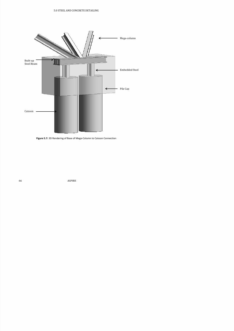
7/17/2019 Structural Design Project of Super Tall Building Chicago Spire
http://slidepdf.com/reader/full/structural-design-project-of-super-tall-building-chicago-spire 82/474
Figure 5.7: 3D Rendering of Base of Mega-Column to Caisson Connection
Mega-column
Embedded Steel
Pile Cap
Built-up
Steel Beam
Caisson
5.0 STEEL AND CONCRETE DETAILING
5.2.2 Base of Outrigger
Across the height of the structure, the exterior columns angle inwards as the diameter of the building
decreases. The intersection of angled and vertical columns will be prefabricated, and the incoming and

7/17/2019 Structural Design Project of Super Tall Building Chicago Spire
http://slidepdf.com/reader/full/structural-design-project-of-super-tall-building-chicago-spire 83/474
g p g
outgoing columns will be spliced to the prefabricated section above and below the connection node.
Moment connections will be needed between the prefabricated column section and the bottom of the
outrigger, the radial girder, and the cantilever. The flanges of the outrigger and column are too thick to
punch through; thus welds will be used for the connection. Two plates will be used in the connection to
improve the constructability of the connection. The first plate will be welded to the face of the column,
and the second plate will be welded to the incoming outrigger and radial girder.
Both flanges and the web of the outrigger will be welded to the end plate. Next, two angles and two
rectangular plates will be welded to the plate and subsequently bolted to the radial girder (Figure 5.8).
For the incoming outrigger, in addition to checking the strength of the welds, several failure modes were
checked including plate yielding in shear and bearing; rupture of beam flange to plate welds; and
beam web shear yielding (Calculation 5.3.1).
Outrigger
Girder
Vertical
Columns
5.0 STEEL AND CONCRETE DETAILING
5.2.3 Outrigger to Core Connection
At each mechanical floor of the tower, outriggers primarily stiffen the connection between the steel
frame and concrete core. These outriggers mainly help reduce the overall structural system’s

7/17/2019 Structural Design Project of Super Tall Building Chicago Spire
http://slidepdf.com/reader/full/structural-design-project-of-super-tall-building-chicago-spire 84/474
lateral deflection. Therefore, to ensure that the outriggers perform in such a way, the outrigger
connection with the concrete core was given major attention.
The outrigger connection consists of two gusset plates that sandwich the flanges of the outrigger
member and radial girder above the mechanical floor (Figure 5.9). Most girders in the building;
however, were oriented with vertical webs and horizontal flanges. The gusset plate connection
required rotating the floor girders by 90 degrees so that the gusset plates can be bolted to the
flanges of both outrigger and girder. Gusset plate bolts were sized and design according to AISCSection J and accounted for failure modes such as block shear and plate yield (Calculation 5.3.2).
Figure 5.9: Elevation of Outrigger and Radial Girder Connection to Concrete Core
The exact connection between the gusset plate and concrete core went through a few design
iterations. Initially, the gusset plates were fillet welded to steel plates bolted to the concrete core,
similar to the typical radial girder connection (Section 5.1.6). However, the high outrigger loads
required around 500 bolts for such a connection Eventually an alternative design was developed
Rotated
Radial Girder
Outrigger
Embedded
Steel Frame
Concrete
Core
5.0 STEEL AND CONCRETE DETAILING
The following assumptions were made for the model.

7/17/2019 Structural Design Project of Super Tall Building Chicago Spire
http://slidepdf.com/reader/full/structural-design-project-of-super-tall-building-chicago-spire 85/474
All members were assumed to be fully braced, simulating the frame’s embedment in concrete.
All beams and columns are connected by moment connections. Connections details would be
designed as per Section 5.1.1.
The top and bottom nodes of the frame are assumed to be fixed in all directions and rotations.
Diagonal braces are added to the frame as compression only truss members (Figure 5.10). These
fictitious members simulate how the concrete struts when the steel frame reacts to load. The brace
sizes are relatively similar to the steel frame members, with steel frame having a greater stiffness toensure that a majority of the load is absorbed by steel instead of concrete.
For the final model, all loads from outriggers are applied axially to the nodes at which outrigger
members connect with the frame. Axial loads are based on from critical load combinations from the
final tower MIDAS model (Figure 5.10).
Figure 5.10: a) Model of Embedded Steel Frame and b) Model with Cross Bracing and Point LoadsThrough iterative design of steel sections, W33x152 members were selected for columns and
W14x665 members for beams. The outriggers and radial girders at the mechanical floor between
Bank 3 and 4 were both W14x730. The W33x152 section when oriented along its weak axis, would
5.0 STEEL AND CONCRETE DETAILING
5.2.4 Top of Mega-Column
The top of the mega-column connection consists of two different connection configurations. Figure
5.11 shows the two scenarios: an interior column angled in one orientation and two exterior

7/17/2019 Structural Design Project of Super Tall Building Chicago Spire
http://slidepdf.com/reader/full/structural-design-project-of-super-tall-building-chicago-spire 86/474
columns angled in two orientations. All of the mega-columns are steel built-up columns.
In addition to the mega-columns, the connection also consists of a vertical built-up terminating at
the top of each mega-column. Although both columns identical steel sections, lower column will be
referred to as the mega-column, and the upper column as the vertical column.
The mega-column and vertical column connection is a prefabricated node. The node is constructed
with shop welded plates extending from the node faces to improve the constructability of the fieldcolumn splice. The column splice will ultimately consist of four plates welded onto the columns to
transfer tension, torsion, and shear. Half of the welds will be done in the shop, and half will be done
in the field. The prefabricated design improves constructability and connection strength. The node
also allows for standard splices that do not have to transfer massive forces and moments over an
angled connection. The radial and circumferential girders will be designed as per Sections 5.1.1
and 5.1.5.
Figure 5.11: 3D Rendering of Mega-Column Connection
5.0 STEEL AND CONCRETE DETAILING
5.2.5 Transfer Column
Transfer columns exist at the mechanical levels where the exterior column radius decreases.
Between Banks 2 and 3 some transfer columns are also designed for the reduction in total exterior
l h f l f d ff f h l

7/17/2019 Structural Design Project of Super Tall Building Chicago Spire
http://slidepdf.com/reader/full/structural-design-project-of-super-tall-building-chicago-spire 87/474
Figure 5.12: Singular Transfer
Column Connection Front and Side
columns. The transfer column connection consists of two different configurations, with typical top
and bottom welded column splices.
The mechanical space between Bank 2 and Bank 3 contains
both of the typical transfer column connections found in the
Chicago Spire. The column grid reduces from 21 columns in
Bank 2 to 14 columns in Bank 3. Seven of the columns in
Bank 2 are designed for the first configuration in Figure5.12. Fourteen of the columns in Bank 2 are designed for the
second configuration in Figure 5.13.
In the first configuration, two field welded column splices
occur at the top of the Bank 2 column and at the bottom of
the Bank 3 column. The connecting member is a
prefabricated connection node that is built to resist
compression, tension, shear, moment, and torsion.
In the second configuration, forces from the Bank 3 column
are transferred to two Bank 2 columns below. Figure 5.13
shows the required angled transfer column. With this
configuration there are three typical field welded column
splices that occur at the top of the Bank 2 column and at the
bottom of the Bank 3 column. The node between Bank 3 andthe angled transfer column split will be prefabricated, along
with the transfer column between the bottom of the node
and the welded column splice at the top of the Bank 2
column.
The welded column connections are comprised of four plates surrounding the members. For each
splice, two plates will be shop welded to the connection node, and two plates will be shop welded to
the columns. Welded column calculations are shown in Calculation 5.1.1.
Figure 5.13: Split Transfer Column
Connection Front and Side Elevation
6.0 FOUNDATION DESIGN AND DETAILING
6.0 Foundation Design and Detailing
The Chicago Spire foundation includes a deep foundation system to support the 150 floor tower
d th fl ki R k k t d i d i il d t f d ti

7/17/2019 Structural Design Project of Super Tall Building Chicago Spire
http://slidepdf.com/reader/full/structural-design-project-of-super-tall-building-chicago-spire 88/474
and the seven floor parking garage. Rock-socketed caissons, driven piles under a mat foundation,concentric top of rock slurry wall rings, and a mat foundation on hardpan were all options to
support the tower. As stated in the provided Geotechnical Report, the latter two options were
considered costly, risky and time consuming. Therefore rock-socketed caisson will be used to
support the tower. The project received city permits to have an allowable net bearing pressure for
the rock of 300 tons per square foot.
The seven floor parking garage will have a retaining wall structure around the perimeter, which
will be internally braced by the floor slabs. The garage will be supported with belled caissons
bearing on hardpan.
6.0 FOUNDATION DESIGN AND DETAILING
6.1 Soil Properties
Information on soil conditions came from eleven test borings and 34 borings to obtain bedrock
cores (Geotechnical Report). The soil profile is 100 to 115 feet of primarily clay overburden on

7/17/2019 Structural Design Project of Super Tall Building Chicago Spire
http://slidepdf.com/reader/full/structural-design-project-of-super-tall-building-chicago-spire 89/474
dolomite bedrock. The site grades range in elevation from +10 to +7 Chicago City Datum (CCD).
The water table is five feet above the CCD. A one foot hardpan layer exists at -71 CCD. A detailed
soil profile is shown in Figure 6.1.
Soil properties were used to calculate apparent earth pressures and pore water pressures for the
foundation design.
Figure 6.1: Provided Soil Profile for Foundation Design
6.0 FOUNDATION DESIGN AND DETAILING
6.2 Retaining Wall Design
The perimeter of the foundation is supported by a 30 in thick,
reinforced concrete retaining wall. The wall was designed to
i h d f il i h h d
OVERTURNING

7/17/2019 Structural Design Project of Super Tall Building Chicago Spire
http://slidepdf.com/reader/full/structural-design-project-of-super-tall-building-chicago-spire 90/474
withstand failure against the earth pressures and pore water
pressure. The thick wall has a high self-weight which helps to
resist the lateral forces from the soil profile. The self-weight
also reduces the chances of bearing failure by distributing the
vertical force to a larger area of soil.
The Geotechnical Report includes a soil profile which consists
of sand and clays. The soil stiffness increases with depth. The
critical soil density is assumed to be 70 pcf to obtain the
worst-case effective pressure producing maximum horizontal
loads on the retaining wall. The buoyant force on soil due to
the ground water table reduces the effective vertical pressure.
A MASTAN analysis of the retaining wall was performed,
modeling the wall as a one way slab assuming the bottom sixfloor slabs from the parking garage brace the retaining wall.
As a conservative approach, the top two slabs are not
considered as bracing for the retaining wall; which leaves a
cantilever span at the top end of the retaining wall. The
retaining wall was checked for overturning, lateral sliding and
bearing failure (Figure 6.2).
The retaining wall is built through a top-down construction
process. The foundation soil is excavated with ring beams
constructed simultaneously at adequate unbraced lengths as
designed by the geotechnical engineer. Ring beams are then
removed from the bottom up as slabs and retaining walls are poured.
The soil layers become stiffer further below the ground surface. At a depth of 85 ft, there is a very
hard clay of undrained shear strength of 15 ksf. The retaining wall sits on this layer and the highbearing capacity prevents bearing failure. Construction joints are provided at every 20 ft to reduce
the longitudinal settlement and tilt.
C l l i 6 1 h h d i f h i i ll
BEARING
FAILURE
L A T E R A L S L I D
I N G
BRACING
HARD
CLAY
Figure 6.2: Failure Modes for
Retaining Wall Design
6.0 FOUNDATION DESIGN AND DETAILING
6.3 Parking Garage Slab Design
The reinforced concrete slab for the parking garage was designed as a two-way slab using the
equivalent frame method, as per ACI 318-08. An expansion joint is built between the two slab
ti t d ki Th f ll i ti d hil d i i th ki

7/17/2019 Structural Design Project of Super Tall Building Chicago Spire
http://slidepdf.com/reader/full/structural-design-project-of-super-tall-building-chicago-spire 91/474
sections to reduce cracking. The following assumptions were made while designing the parking
garage slab.
All slab design assumes rectangular slab sections designed to the maximum span calculated from
column locations in provided floor plans.
Outside of the building footprint, columns are spaced in an orthogonal grid.
Inside the building footprint, columns offset from an assumed orthogonal gridline by 6 ft or less
are considered on that gridline.
Core and foundation caissons bear the slab load.
Slabs are designed as cantilevers to the retaining walls.
Deformed Welded Wire Reinforcement (WWR) is used for flexural reinforcing design, Fy = 80
ksi.
Light weight concrete is used with a density, ρc = 110 pcf and a 28-day compressive strength,
f’c = 4000 psi.
Diameter of circular columns is 32 in. The slab was designed without interior beams or edge beams.
The parking slab design utilized MASTAN to model the moment frame connections between the
caissons and parking slabs for all seven floors. Design loads Section 2.4 were used to find the
maximum positive and negative moments along the slab. Per ACI 318-08, 13.2.1 and 13.6.4.1, the
critical moments are proportionally distributed to the column and middle strips of the slab width.
Drop panels were designed at the top of each column to reduce negative moment reinforcement.
The ultimate slab design was 12 in thick. The design does not call for interior or edge beams
because of the high strength WWR used for flexural reinforcement. WWR can be costly; however,
for large projects the steel savings outweigh the material cost
The design process and calculations are summarized in Calculation 6.2.1.
6.0 FOUNDATION DESIGN AND DETAILING
6.4 Bell Caisson Design
Belled Caissons are used to support the parking garage slab. Caissons were designed following
Chapter I: Design of Composite Members in the AISC Steel Construction Manual. Circular reinforced
concrete columns were used in the parking garage extending below the bottom slab into belled

7/17/2019 Structural Design Project of Super Tall Building Chicago Spire
http://slidepdf.com/reader/full/structural-design-project-of-super-tall-building-chicago-spire 92/474
concrete columns were used in the parking garage, extending below the bottom slab into belled
caissons, which rest on the hardpan at an elevation of 92 ft below the top slab of the parking garage.
The bell shape was needed to lower the applied pressure on the soil. The bell design minimized the
bearing pressure to be within the allowable pressure of 45 ksf. The columns unbraced lengths were
based on support from the parking garage slabs. The columns were designed as reinforced
concrete columns with steel reinforcing or W-shapes depending on the column load.
Calculation 6.2.3 follows the AISC procedure for bell caisson design. Figure 6.3 shows an elevationof the foundation and belled caissons.
Figure 6.3: Elevation of Bell Caissons
6.0 FOUNDATION DESIGN AND DETAILING
6.5 Rock-Socketed Caisson
6.5.1
Column Design
Caissons of 10 ft diameter using 14 ksi concrete were designed to carry the load from the core and

7/17/2019 Structural Design Project of Super Tall Building Chicago Spire
http://slidepdf.com/reader/full/structural-design-project-of-super-tall-building-chicago-spire 93/474
Caissons of 10 ft diameter using 14 ksi concrete were designed to carry the load from the core and
mega-columns to the bed rock. Each mega-column is supported by two caissons, whereas the core
is supported by 20 caissons. The caissons are socketed into the bed rock; limiting the settlement of
the caissons. Figure 6.4 shows an elevation view of the core and mega-column caissons.
Figure 6.4: Elevation of Rock-Socketed Caissons
Each caisson is a steel cylinder filled with concrete (Figure 6.5). The steel cylinder prevents any
soil-concrete interaction and provides a higher strength to the caisson due to composite action.
There is no uplift friction on the caisson by soil, as the steel provides a smooth surface withnegligible vertical friction. Stresses induced in the caisson due to the loads from super structure
are well within the allowable limits.
Mega-Column
Caisson
Mega-Column
Caisson
Core
Caissons
Bedrock
6.0 FOUNDATION DESIGN AND DETAILING

7/17/2019 Structural Design Project of Super Tall Building Chicago Spire
http://slidepdf.com/reader/full/structural-design-project-of-super-tall-building-chicago-spire 94/474
Figure 6.5: Detail of Caisson
Settlement is the controlling criteria in the design of caissons, as a higher differential settlement
may lead to severe structural damages. A stiffer base material provides greater resistance to the
settlement in the caisson. The loads carried by the caissons are obtained from the MIDAS-GEN
model and the Geotechnical Report. Three limit states, shown in Figure 6.6 were checked for the
caisson design (Calculation 6.3).
6.0 FOUNDATION DESIGN AND DETAILING
6.5.2 Ring Beam
A reinforced concrete ring beam was designed to connect the core walls to the rock-socketed
caissons. This will ensure a uniform distribution of the axial load to the 20 caissons. The ring beam
will also dissipate the shear force. The shear force is resisted by the passive earth pressure of the

7/17/2019 Structural Design Project of Super Tall Building Chicago Spire
http://slidepdf.com/reader/full/structural-design-project-of-super-tall-building-chicago-spire 95/474
ring pushing against the soil, by the friction between the soil and the slab, and by the bottom of the
ring beam. Figure 6.7 shows an elevation of the ring beam and its relation to the slab, core wall, and
rock-socketed caisson. Figure 6.8 shows the ring beam’s resistance to the horizontal soil pressure.
Figure 6.7: Elevation of Ring Beam
Soil Pressure
6.0 FOUNDATION DESIGN AND DETAILING
6.5.3 Finite Element Model
An ABAQUS model was developed to perform a finite element analysis and monitor the stresses in
the rock-socketed caisson. Each mega-column is supported by two circular caissons. These mega-
columns are inclined, which exerts a compressive pressure and a horizontal shear on the caissons

7/17/2019 Structural Design Project of Super Tall Building Chicago Spire
http://slidepdf.com/reader/full/structural-design-project-of-super-tall-building-chicago-spire 96/474
below it. The loads carried by the caissons were obtained from the MIDAS Gen model. Since the
caissons are encased in a steel cylinder, the vertical soil friction is negligible, and is not considered.
The following material properties are used in the ABAQUS model.
Young`s modulus of bedrock, Er = 3500 ksi
Poisson`s ratio of the bedrock, ν = 0.28
Friction coefficient for bed rock and caisson interaction = 0.3 Directionality of the friction is isotopic.
For the caisson and bedrock socket, interaction property is modeled as contact, and the contact
property is modeled as tangential. The bedrock and caisson are constrained as ties, where the
caisson is the master surface and the bedrock is the slave surface. After performing iterations to
obtain an optimum mesh configuration, the caisson and bedrock were meshed as triangular
elements.
The following stresses are obtained from the finite element analysis.
Caisson
Bedrock
6.0 FOUNDATION DESIGN AND DETAILING
It can be seen in Figure 6.9 that the maximum stresses occur at the top surface of the caisson. The
stresses decrease as we move down towards the middle portion of the caisson and at the
interaction of caisson and bedrock, higher stresses are encountered.
Table 6.1: Critical Von Mises Stresses from ABAQUS Model

7/17/2019 Structural Design Project of Super Tall Building Chicago Spire
http://slidepdf.com/reader/full/structural-design-project-of-super-tall-building-chicago-spire 97/474
Von Mises Stress Top Face Bottom Face
Maximum Compression stress (ksi) 6.3 3.7
Maximum Tension stress (ksi) 4.9 1.9
7.0 LONG-TERM DEFLECTION EFFECTS
7.0 Long-Term Deflection Effects
The aim of the creep and shrinkage calculations for the core and the columns is to determine the
deflection in each and the differential between the two. It can be predicted that the steel columns
will have minimal shrinkage as compared to the core, so this should be accounted for during

7/17/2019 Structural Design Project of Super Tall Building Chicago Spire
http://slidepdf.com/reader/full/structural-design-project-of-super-tall-building-chicago-spire 98/474
construction. Things to consider in this calculation will include the construction schedule, curing
conditions, loads, geometry, and strength of the concrete and steel.
When a load is applied on the structure, there is an initial elastic strain, which occurs when the load
is placed on the column. In addition to this, there is a creep strain, which starts when a load is
applied, and a shrinkage strain, which begins as the concrete begins to dry. Both of these increase
over time and approach the ultimate strain value. The ultimate creep coefficient and shrinkage
strain are both determined by the curing conditions, the concrete mixture, and the construction
schedule. All of the calculated values for deflection will need to be considered in the final
construction to meet serviceability requirements, particularly the difference between the
deformation in the core and the columns.
7.0 LONG-TERM DEFLECTION EFFECTS
7.1 Conceptual Summary
The aim of this chapter is to determine the creep and shrinkage of concrete in the core, as well as
elastic deformations in both the core and columns. It is very important to evaluate the differential
deformation between the core and columns to alleviate unexpected stresses and deformations. It

7/17/2019 Structural Design Project of Super Tall Building Chicago Spire
http://slidepdf.com/reader/full/structural-design-project-of-super-tall-building-chicago-spire 99/474
can be predicted that the steel columns will have minimal deformation as compared to the core, so
this will need to be accounted for during construction. Variables to consider in the deformation
calculations will include the construction schedule, curing conditions, loads, geometry, and strength
of the concrete and steel.
When a load is applied on a steel column or the concrete core, there is an initial elastic strain, which
occurs when the load is added. In addition to the immediate elastic strain, in the concrete core
there is a long-term creep strain, which starts when a load is applied, and a long-term shrinkage
strain, which begins as the concrete begins to dry. Both of these long-term strains increase over
time and approach the ultimate strain value. The ultimate creep coefficient and shrinkage strain
are both affected by the curing conditions, the concrete mixture, and the construction schedule. All
of the calculated values will need to be considered in the final construction to meet serviceability
requirements, particularly the differential deformation between the core and the columns.
7.0 LONG-TERM DEFLECTION EFFECTS
7.2 Creep and Shrinkage Analysis
Several simplifying assumptions about the core composition and geometry were made in the
analysis. The 28-day strength of the concrete is 14,000 psi as specified earlier in the project. Per
ACI 209R, t he GL2000 method assumes the concrete’s elastic modulus is a function of the strength,
d ifi i d d f i l l h l h i i i i

7/17/2019 Structural Design Project of Super Tall Building Chicago Spire
http://slidepdf.com/reader/full/structural-design-project-of-super-tall-building-chicago-spire 100/474
and specifies a time-dependent function to calculate the actual strength at any given point in time,
as indicated in Figure 7.1 and Figure 7.2.
Figure 7.1: Concrete Strength Gain with Time
7.0 LONG-TERM DEFLECTION EFFECTS
The core was assumed to be a cylindrical tube of concrete, with constant radius and thickness
throughout each bank. The amount of steel reinforcement within the core was calculated
previously, so the values from that calculation were used in this analysis. Appendix 9.14, Table 9.15
outlines core properties and dimensions used in the analysis. In addition, per the recommendation
of a professional engineer, the core will be analyzed using the same model and methods as a typical
column

7/17/2019 Structural Design Project of Super Tall Building Chicago Spire
http://slidepdf.com/reader/full/structural-design-project-of-super-tall-building-chicago-spire 101/474
column.
The construction schedule of the spire was extremely important to the creep and shrinkage
calculations. Aspire assumed a 4-day cycle for floor construction, meaning a new floor would be
added every 4 days. Although this seemed like a very fast-paced schedule, it is important to note
that the Burj Khalifa was constructed successfully using a 3-day cycle (Abdelrazaq, 2008). In
addition, three simplifying assumptions for analysis were made:
Curing time: 4 days
Loading age: 4 days
Construction loads occupy the top 4 floors at any given point during construction.
It is important to note that these assumptions may not be entirely realistic, but will give
conservative values for strain. The construction loads are assumed to be mainly composed of heavy
machinery and lifting equipment, which will move up the spire as new floors are constructed. Once
the construction period has ended these loads will no longer exist.
The exact sequence of construction was not considered. After consulting professional engineers,
ASPIRE concluded that the main focus of this analysis should be the long-term deformations of the
Spire, which will not be significantly affected by the order of construction.
Due to the increased loading near the base of the tower compared to the top, the Spire was split up
into 13 vertical segments. The middle floor of each of these segments was considered to be
representative of the average deformation of the floors in the segment, and was analyzed. The floor
deformation for that middle floor was then multiplied by the number of floors in the segment,
giving a total deformation for the segment. The sum of the segment deformations results in the
total building deformation.
During the analysis, it was observed that the long-term creep and shrinkage rates had tapered off
around 20 years, so the analysis was completed for a 20 year span from the start of construction.This is consistent with ultimate creep values being calculated after 20 years of loading.
7.0 LONG-TERM DEFLECTION EFFECTS
7.2.1 Columns
All the vertical columns in the spire were designed as built-up steel members, so they will not be
affected by any noticeable creep or shrinkage. As such, they were only analyzed for the elastic
deformation due to loading. The elastic deformation was calculated by:

7/17/2019 Structural Design Project of Super Tall Building Chicago Spire
http://slidepdf.com/reader/full/structural-design-project-of-super-tall-building-chicago-spire 102/474
The elastic strain analysis resulted in an overall deflection of 6.77 inches expected in the steel
columns over the 150-story building. See Appendix 9.14, Table 9.16 for the tabulated results for
each floor segment and Appendix 9.14.1 for a representative calculation of the strains. Calculation
7.1 summarizes the steel column deformation.
7.2.2 Core
The core analysis required that creep and shrinkage were considered, though they were negligible
or nonexistent in the steel columns. The effects of creep and shrinkage were calculated using the
GL2000 model. See Appendix 9.14.3 for a step-by-step qualitative approach to using the GL2000
model, and Appendix 9.14.1 for an example calculation. Calculation 7.2 summarizes the concrete
core deformation.
In the GL2000 model, several variables need to be chosen by the designer. The only variable
related to the concrete mix design is the cement type. The GL2000 can be used with Type I, II, or III
cements, which the designer must choose between. A sensitivity analysis revealed that Type III
cement will result in the lowest creep and shrinkage values, most likely due to its rapid initial
strength gain.
Table 7.1: Cement Type Deformation Sensitivity Analysis
Cement Type
Ultimate
Deformation
Type I 24.79
Type II 24.91Type III 23.95
7.0 LONG-TERM DEFLECTION EFFECTS
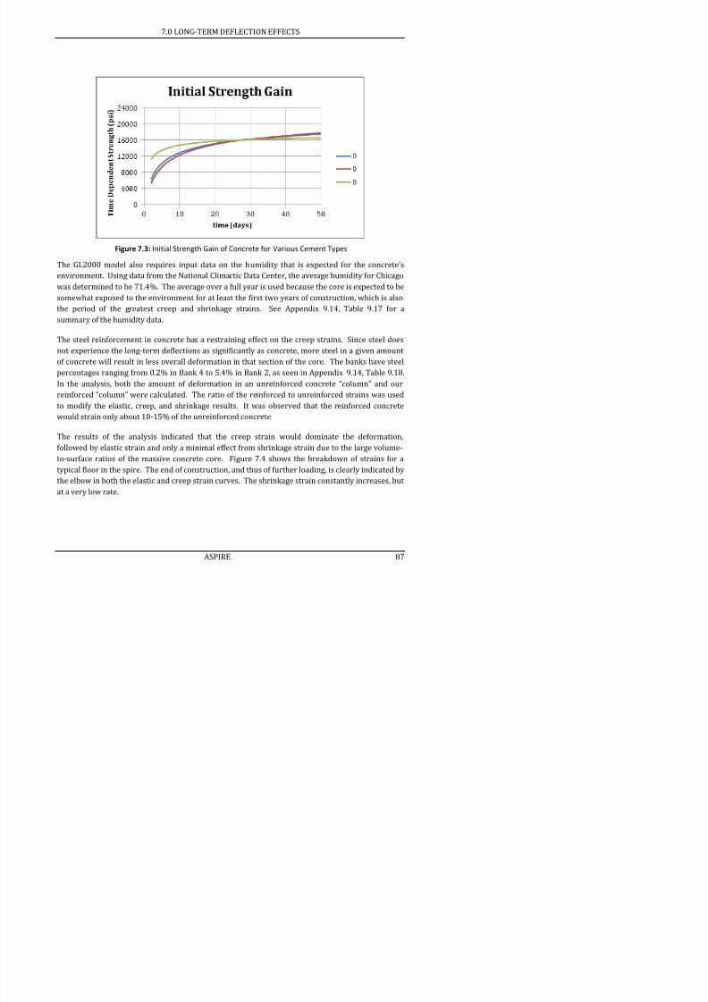
7/17/2019 Structural Design Project of Super Tall Building Chicago Spire
http://slidepdf.com/reader/full/structural-design-project-of-super-tall-building-chicago-spire 103/474
Figure 7.3: Initial Strength Gain of Concrete for Various Cement Types
The GL2000 model also requires input data on the humidity that is expected for the concrete’s
environment. Using data from the National Climactic Data Center, the average humidity for Chicago
was determined to be 71.4%. The average over a full year is used because the core is expected to be
somewhat exposed to the environment for at least the first two years of construction, which is also
the period of the greatest creep and shrinkage strains. See Appendix 9.14, Table 9.17 for a
summary of the humidity data.
The steel reinforcement in concrete has a restraining effect on the creep strains. Since steel doesnot experience the long-term deflections as significantly as concrete, more steel in a given amount
of concrete will result in less overall deformation in that section of the core. The banks have steel
percentages ranging from 0.2% in Bank 4 to 5.4% in Bank 2, as seen in Appendix 9.14, Table 9.18.
In the analysis, both the amount of deformation in an unreinforced concrete “column” and our
reinforced “column” were calculated. The ratio of the reinforced to unreinforced strains was used
to modify the elastic, creep, and shrinkage results. It was observed that the reinforced concrete
would strain only about 10-15% of the unreinforced concrete.
The results of the analysis indicated that the creep strain would dominate the deformation,
followed by elastic strain and only a minimal effect from shrinkage strain due to the large volume-
7.0 LONG-TERM DEFLECTION EFFECTS

7/17/2019 Structural Design Project of Super Tall Building Chicago Spire
http://slidepdf.com/reader/full/structural-design-project-of-super-tall-building-chicago-spire 104/474
Figure 7.4: Typical Strain Values for a Single Floor
The analysis of the creep and shrinkage for concrete resulted in an overall expected deformation of24.8 inches in the core. As can be seen in Table 7.2, approximately 75% of the ultimate deflection
occurs in the first two years, but there is still substantial movement out to 20 years, resulting in the
ultimate deformation of 24.8 in.
Table 7.2: Core Total Deformations
Time
(yr)
Deformation
(in)
Percentage of
Deformation
0 0 0%
2 18.8 76%
3 20.0 81%
10 23.0 93%
20 24.8 100%
Figure 7.5 breaks down the core deformations by floor. It is clearly seen that a majority of the
7.0 LONG-TERM DEFLECTION EFFECTS

7/17/2019 Structural Design Project of Super Tall Building Chicago Spire
http://slidepdf.com/reader/full/structural-design-project-of-super-tall-building-chicago-spire 105/474
Figure 7.5: Core Deformations per Floor
7.0 LONG-TERM DEFLECTION EFFECTS
7.3 Conclusion and Recommendations
The creep and shrinkage strain analysis resulted in very different deformations between the core
and the surrounding steel columns. As displayed in Table 7.3, the 24.8-inch deformation in the core
is greater than the 6.77-inch deformation in the steel by 18.0 inches. This differential deformation
can be very dangerous in tall buildings. Not only could aesthetically displeasing cracks form, but

7/17/2019 Structural Design Project of Super Tall Building Chicago Spire
http://slidepdf.com/reader/full/structural-design-project-of-super-tall-building-chicago-spire 106/474
serious structural issues could result as well. If this deformation is not designed for, as the core
deforms more than the columns, the floors will become slanted and connections will become
overstressed.
Table 7.3: 20-Year Deformation Comparisons
Core Deformation: 24.8 in
Steel Deformation: 6.77 in
Core-Column Difference: 18.0 in
Compensation / floor required: 0.12 in
To compensate for the differential settlement, the core should be built approximately 18 in higher
than the original design calls for. Since the creep and shrinkage model is inherently inaccurate up
to 20 -30%, additional height should be added in addition to the 18 in. For comparison, the Burj
Khalifa designers estimated a 12 in deformation in their core, but increased the design height of the
core by 22 in (Baker et al., 2007). Aspire recommends approximately a 30 in increase in the core
height based on this preliminary analysis to account for uncertainties.
As can be seen in Figure 7.6, the majority of the strains in the core will take place during the
construction period. This fact means that by the time the building needs to be serviceable, most ofits deformation will have occurred and need not be designed for. Also, the additional height that
was added for each floor-to-floor height will not be as noticeable throughout the life of the
structure. Rather, the floors will appear level and as designed for the tenants.
7.0 LONG-TERM DEFLECTION EFFECTS
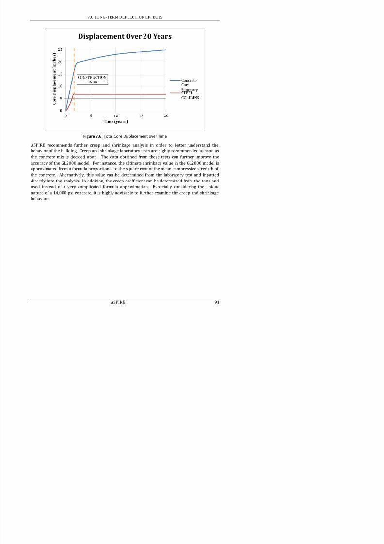
7/17/2019 Structural Design Project of Super Tall Building Chicago Spire
http://slidepdf.com/reader/full/structural-design-project-of-super-tall-building-chicago-spire 107/474
Figure 7.6: Total Core Displacement over Time
ASPIRE recommends further creep and shrinkage analysis in order to better understand the
behavior of the building. Creep and shrinkage laboratory tests are highly recommended as soon as
the concrete mix is decided upon. The data obtained from those tests can further improve the
accuracy of the GL2000 model. For instance, the ultimate shrinkage value in the GL2000 model is
approximated from a formula proportional to the square root of the mean compressive strength of
the concrete. Alternatively, this value can be determined from the laboratory test and inputted
directly into the analysis. In addition, the creep coefficient can be determined from the tests and
used instead of a very complicated formula approximation. Especially considering the unique
nature of a 14,000 psi concrete, it is highly advisable to further examine the creep and shrinkage
behaviors.
8.0 REFERENCES
8.0 References
Abdelrazaq, A., Kim, K. J. & Kim, J. H. (2008). “Brief on the Construction Planning of the Burj Dubai
Project, Dubai, UAE. Proceedings of the CTBUH 8th World Congress, 3rd-5th March 2008.
Dubai, UAE.” Published by the Council on Tall Buildings and Urban Habitat, Chicago. pp.
386-394.

7/17/2019 Structural Design Project of Super Tall Building Chicago Spire
http://slidepdf.com/reader/full/structural-design-project-of-super-tall-building-chicago-spire 108/474
American Concrete Institute. “Guide for Modeling and Calculating Shrinkage and Creep in Hardened
Concrete (ACI 209.2R-08).” ACI Manual of Concrete Practice, Part 1, 2010.
American Concrete Institute. ACI 318-08 Building Code and Commentary . 2008.
American Institute of Steel Construction. “Floor Vibrations Due to Human Activity.” American
Institute of Steel Construction, Steel Design Guide Series 11. 2003.
American Institute of Steel Construction. Steel Construction Manuel Thirteenth Edition, 2008.
American Institute of Steel Construction. Engineering for Steel Construction: A Source Book on
Connections, 1984.
American Society of Civil Engineers. Minimum Design Loads for Buildings and Other Structures.
2006. Reston, Virginia: American Society of Civil Engineers, 2006.
American Society of Civil Engineers. Minimum Design Loads for Buildings and Other Structures.
2010. Reston, Virginia: American Society of Civil Engineers, 2010.
Baker, William F. “Energy-Based Design of Lateral Systems.” Structural Engineering International .
Vol 2. No 2. 1 May 1992. p 99-102.
Baker et al. “Creep and Shrinkage and the Design of Supertall Buildings – A Case Study: The Burj
Dubai Tower.” American Concrete Institute. Special Publication, volume 246, pp. 133-148.
1 Sept 2007.
Binder, Georges. One Hundred and One of the World's Tallest Buildings. Australia: The Images
Publishing Group Pty Ltd, 2006. Google Books.
Blodgett, Omer W. Design of Welded Structures. Cleveland, OH: Lincoln, 1972. 8.2-2. Print.
"Chicago Spire " SkyScraperPage Skyscraper Source Media 2011 Web 14 Sep 2011
8.0 REFERENCES
Smith, S.E. “What Is a Mechanical Floor?” 29 July 2011. wiseGEEK.com. 15 Sep. 2011
<http://www.wisegeek.com/what-is-a-mechanical-floor.htm>.
Taranath, Bungale S. Steel, Concrete, & Composite Design of Tall Buildings. New York City: McGraw-
Hill Book Company, 1998.
Taranath, Bungale S. Structural Analysis & Design of Tall Buildings . New York City: McGraw-Hill

7/17/2019 Structural Design Project of Super Tall Building Chicago Spire
http://slidepdf.com/reader/full/structural-design-project-of-super-tall-building-chicago-spire 109/474
, g y g f g y
Book Company, 1988. Print.
Wight, J. and James MacGregor. Reinforced Concrete Mechanics & Design, Fifth Edition. Upper Saddle
River, NJ: Pearson Prentice Hall. 2009
Vulcraft. VULCRAFT Steel Roof & Floor Deck, 2008.
9.0 APPENDIX
9.0 Appendix
Appendix consists of supplementary information and summary tables. Following the appendix are
sample calculation and the complete structural drawing set.
Note that a “--“ indicates that the size, length, dimension, percentage, etc. is not applicable for the
given cell

7/17/2019 Structural Design Project of Super Tall Building Chicago Spire
http://slidepdf.com/reader/full/structural-design-project-of-super-tall-building-chicago-spire 110/474
given cell.
9.0 APPENDIX
9.1 Gravity Design Loads
Typical Floor
Dead
Load
Superimposed
Dead Load
Live
Load
(psf) (psf) (psf)
Lobby

7/17/2019 Structural Design Project of Super Tall Building Chicago Spire
http://slidepdf.com/reader/full/structural-design-project-of-super-tall-building-chicago-spire 111/474
Decking and Slab1 32
Assembly Areas (lobbies) 100
Acoustical fiber board 1
MEP Duct Allowance 10
Ceramic or quarry tile (1 1/2 in) on 1 in. mortar bed2 46
Total 32 57 100
Residential
Decking and Slab1 33
Private rooms and corridors serving them 40
Partition Walls 15
Acoustical fiber board 1
Ceramic or quarry tile (3/4 in) on 1 in. mortar bed 23MEP Duct Allowance 10
Total 33 34 55
Mechanical
Decking and Slab1 39
Catwalks 40
Machine Space 200
MEP Duct Allowance 10Total 39 10 240
Parking
Slab (150 pcf @ 12 in.)3 150
Garages (passenger vehicles only) 40
MEP Duct Allowance 10
Cement finish (1-in.) on stone-concrete fill 32
Total 150 42 40
Core
Slab (110 pcf @ 6 in.) 3
55
9.0 APPENDIX
9.2 RWDI Recommended Wind Load
Table 9.1: RWDI Wind Load Combinations
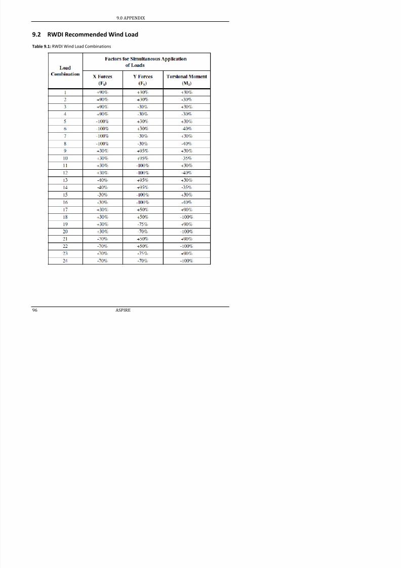
7/17/2019 Structural Design Project of Super Tall Building Chicago Spire
http://slidepdf.com/reader/full/structural-design-project-of-super-tall-building-chicago-spire 112/474
9.0 APPENDIX
Table 9.2: RWDI Provided Wind Forces and Torsional Moments
Floor
Fx
(kips)
Fy
(kips)
Torsional Moment, Mz
(kip-ft)
Critical Overturning
Moment (kip-ft x 106)
Critical Force
(kips)
1 27 20 44 9.41 27.42 53 40 96 9.28 54.6
3 53 40 102 9.16 54.4

7/17/2019 Structural Design Project of Super Tall Building Chicago Spire
http://slidepdf.com/reader/full/structural-design-project-of-super-tall-building-chicago-spire 113/474
4 53 40 109 9.04 54.4
5 53 40 144 8.92 54.5
6 53 40 195 8.80 54.4
7 53 40 212 8.68 54.3
8 53 41 233 8.56 54.49 53 41 239 8.45 54.3
10 53 41 240 8.33 54.2
11 53 41 252 8.21 54.1
12 53 41 264 8.10 54.2
13 53 41 275 7.98 54.4
14 53 41 287 7.87 54.4
15 53 42 298 7.76 54.516 53 42 306 7.64 54.7
17 53 42 314 7.53 54.7
18 53 42 324 7.42 54.9
19 53 43 335 7.31 54.9
20 54 43 345 7.20 55.1
21 54 43 354 7.09 55.2
22 54 44 364 6.98 55.423 54 44 372 6.88 55.6
24 54 44 381 6.77 55.8
25 54 45 392 6.66 56.0
26 54 45 399 6.56 56.1
27 55 45 411 6.45 56.3
28 55 46 418 6.35 56.5
29 55 46 427 6.25 56.730 55 46 433 6.14 56.9
31 55 47 443 6.04 57.2
32 56 47 451 5 94 57 4
9.0 APPENDIX
Floor
Fx
(kips)
Fy
(kips)
Torsional Moment, Mz
(kip-ft)
Critical Overturning
Moment (kip-ft x 106)
Critical Force
(kips)
39 57 49 470 5.26 58.7
40 57 49 470 5.16 58.7
41 56 49 437 5.07 57.7
42 56 49 442 4.98 58.0
43 56 49 447 4 88 58 1
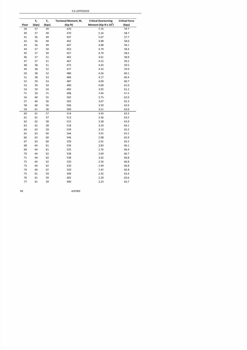
7/17/2019 Structural Design Project of Super Tall Building Chicago Spire
http://slidepdf.com/reader/full/structural-design-project-of-super-tall-building-chicago-spire 114/474
43 56 49 447 4.88 58.1
44 57 50 453 4.79 58.4
45 57 50 457 4.70 58.5
46 57 51 465 4.61 58.9
47 57 51 467 4.52 59.2
48 58 51 473 4.43 59.5
49 58 52 477 4.35 59.9
50 58 52 480 4.26 60.1
51 58 53 484 4.17 60.4
52 59 53 487 4.09 60.7
53 59 54 490 4.00 61.0
54 59 54 492 3.92 61.2
55 59 55 498 3.84 61.6
56 60 55 502 3.75 62.0
57 60 56 503 3.67 62.3
58 60 56 506 3.59 62.6
59 61 56 509 3.51 63.0
60 61 57 514 3.43 63.3
61 61 57 513 3.36 63.5
62 62 58 515 3.28 63.9
63 62 58 518 3.20 64.1
64 63 59 539 3.13 65.2
65 63 60 544 3.05 65.5
66 63 60 546 2.98 65.9
67 63 60 529 2.91 65.5
68 64 61 534 2.83 66.1
69 64 61 535 2.76 66.4
70 64 62 538 2.69 66.7
71 64 62 538 2.62 66.8
9.0 APPENDIX
Floor
Fx
(kips)
Fy
(kips)
Torsional Moment, Mz
(kip-ft)
Critical Overturning
Moment (kip-ft x 106)
Critical Force
(kips)
78 62 60 403 2.16 64.0
79 62 60 406 2.10 64.6
80 62 60 400 1.99 64.6
81 62 60 399 1.98 64.7
82 63 61 399 1 92 65 1

7/17/2019 Structural Design Project of Super Tall Building Chicago Spire
http://slidepdf.com/reader/full/structural-design-project-of-super-tall-building-chicago-spire 115/474
82 63 61 399 1.92 65.1
83 63 61 399 1.86 65.4
84 63 62 402 1.80 65.9
85 63 62 398 1.74 66.0
86 64 62 401 1.69 66.5
87 64 63 403 1.63 66.9
88 64 63 400 1.58 67.1
89 65 64 401 1.52 67.6
90 65 64 396 1.47 67.6
91 65 64 398 1.42 68.2
92 66 65 401 1.36 68.6
93 66 65 399 1.31 68.9
94 66 65 394 1.27 69.0
95 66 66 389 1.22 69.3
96 67 66 388 1.17 69.6
97 67 66 368 1.12 69.9
98 68 67 387 1.08 70.4
99 68 67 385 1.03 70.6
100 68 68 384 0.99 71.2
101 69 68 386 0.95 71.8
102 69 68 382 0.90 72.0
103 70 69 384 0.86 72.8
104 70 69 383 0.82 73.2
105 71 69 382 0.78 73.7
106 71 69 383 0.74 74.1
107 72 69 382 0.71 74.6
108 72 69 380 0.67 74.9
109 70 69 381 0.64 73.0
110 70 69 381 0.60 73.0
9.0 APPENDIX
Floor
Fx
(kips)
Fy
(kips)
Torsional Moment, Mz
(kip-ft)
Critical Overturning
Moment (kip-ft x 106)
Critical Force
(kips)
117 70 68 315 0.39 72.9
118 71 68 312 0.36 73.4
119 71 69 310 0.34 73.9
120 71 69 307 0.31 74.0
121 72 69 304 0.29 74.6

7/17/2019 Structural Design Project of Super Tall Building Chicago Spire
http://slidepdf.com/reader/full/structural-design-project-of-super-tall-building-chicago-spire 116/474
121 72 69 304 0.29 74.6
122 78 76 314 0.27 80.9
123 70 68 260 0.24 73.0
124 66 63 266 0.22 68.4
125 67 64 264 0.20 69.2
126 67 64 258 0.19 69.2
127 66 64 251 0.17 68.8
128 67 64 248 0.15 69.2
129 67 64 242 0.13 69.7
130 68 64 237 0.12 70.6
131 69 65 233 0.10 71.2
132 69 65 225 0.09 71.2
133 68 64 217 0.08 70.9
134 68 64 211 0.07 70.8
135 68 64 202 0.06 70.2
136 67 63 193 0.05 69.6
137 67 62 185 0.04 69.2
138 66 62 176 0.03 68.3
139 65 60 165 0.02 67.1
140 62 58 148 0.02 64.5
141 59 55 129 0.01 61.7
142 76 71 115 0.01 78.8
143 71 67 104 0.00 73.8
144 55 51 92 0.00 56.6
145 59 55 92 0.00 60.8
146 59 55 92 0.00 60.8
9.0 APPENDIX
9.3 Seismic Load Summary
Floor LevelFloor
Type1
Lateral Force, Fx Story Shear , Vx Moment (Mx)
(kips) (kips) (kip-ft x 106
)1 L 0.01 6,563 8.82
2 L 0.05 6,563 8.74

7/17/2019 Structural Design Project of Super Tall Building Chicago Spire
http://slidepdf.com/reader/full/structural-design-project-of-super-tall-building-chicago-spire 117/474
3 L 0.11 6,563 8.65
4 L 0.19 6,563 8.56
5 L 0.3 6,563 8.48
6 R 0.43 6,562 8.39
7 R 0.58 6,562 8.308 R 0.76 6,561 8.22
9 R 0.96 6,560 8.13
10 R 1.18 6,560 8.04
11 R 1.43 6,558 7.96
12 R 1.7 6,557 7.87
13 R 2 6,555 7.79
14 R 2.32 6,553 7.7015 R 2.66 6,551 7.61
16 R 3.03 6,548 7.53
17 R 3.42 6,545 7.44
18 R 3.83 6,542 7.35
19 R 4.27 6,538 7.27
20 R 4.73 6,534 7.18
21 R 5.22 6,529 7.10
22 R 5.73 6,524 7.01
23 R 6.26 6,518 6.92
24 R 6.81 6,512 6.84
25 R 7.39 6,505 6.75
26 R 8 6,498 6.67
27 R 8.62 6,490 6.58
28 R 9.28 6,481 6.50
29 R 9.95 6,472 6.41
30 R 10.65 6,462 6.33
31 R 11.37 6,451 6.24
9.0 APPENDIX
Floor LevelFloor
Type1
Lateral Force, Fx Story Shear , Vx Moment (Mx)
(kips) (kips) (kip-ft x 106)
39 M 26.51 6,330 5.57
40 L 15.46 6,303 5.4941 R 15.69 6,288 5.40
42 R 16.46 6,272 5.32
43 R 17 26 6 256 5 24

7/17/2019 Structural Design Project of Super Tall Building Chicago Spire
http://slidepdf.com/reader/full/structural-design-project-of-super-tall-building-chicago-spire 118/474
43 R 17.26 6,256 5.24
44 R 18.07 6,238 5.16
45 R 18.9 6,220 5.07
46 R 19.75 6,201 4.99
47 R 20.62 6,182 4.9148 R 21.5 6,161 4.83
49 R 22.41 6,140 4.75
50 R 23.33 6,117 4.67
51 R 24.27 6,094 4.59
52 R 25.24 6,070 4.51
53 R 26.22 6,044 4.43
54 R 27.21 6,018 4.35
55 R 28.23 5,991 4.27
56 R 29.27 5,963 4.19
57 R 30.32 5,933 4.11
58 R 31.4 5,903 4.04
59 R 32.49 5,872 3.96
60 R 33.6 5,839 3.88
61 R 34.73 5,806 3.80
62 R 35.88 5,771 3.73
63 R 37.04 5,735 3.65
64 R 38.23 5,698 3.58
65 R 39.43 5,660 3.50
66 R 40.65 5,620 3.43
67 R 41.89 5,580 3.36
68 R 43.15 5,538 3.28
69 R 44.43 5,495 3.21
70 R 45.73 5,450 3.14
71 R 47.05 5,404 3.07

7/17/2019 Structural Design Project of Super Tall Building Chicago Spire
http://slidepdf.com/reader/full/structural-design-project-of-super-tall-building-chicago-spire 119/474
9.0 APPENDIX
Floor LevelFloor
Type1
Lateral Force, Fx Story Shear , Vx Moment (Mx)
(kips) (kips) (kip-ft x 106)
119 R 60.59 2,444 0.52
120 R 61.61 2,383 0.49121 R 62.64 2,322 0.46
122 R 63.68 2,259 0.43
123 R 64 73 2 195 0 40
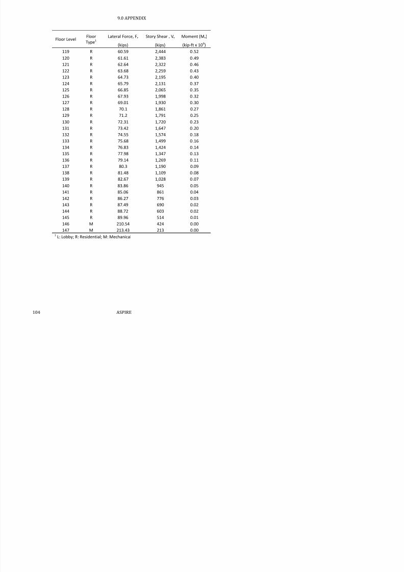
7/17/2019 Structural Design Project of Super Tall Building Chicago Spire
http://slidepdf.com/reader/full/structural-design-project-of-super-tall-building-chicago-spire 120/474
123 R 64.73 2,195 0.40
124 R 65.79 2,131 0.37
125 R 66.85 2,065 0.35
126 R 67.93 1,998 0.32
127 R 69.01 1,930 0.30128 R 70.1 1,861 0.27
129 R 71.2 1,791 0.25
130 R 72.31 1,720 0.23
131 R 73.42 1,647 0.20
132 R 74.55 1,574 0.18
133 R 75.68 1,499 0.16
134 R 76.83 1,424 0.14
135 R 77.98 1,347 0.13
136 R 79.14 1,269 0.11
137 R 80.3 1,190 0.09
138 R 81.48 1,109 0.08
139 R 82.67 1,028 0.07
140 R 83.86 945 0.05
141 R 85.06 861 0.04
142 R 86.27 776 0.03
143 R 87.49 690 0.02
144 R 88.72 603 0.02
145 R 89.96 514 0.01
146 M 210.54 424 0.00
147 M 213.43 213 0.001 L: Lobby; R: Residential; M: Mechanical
9.0 APPENDIX
9.4 Core Slab Design Summary
All core slabs are 6 in. thick, 110 pcf lightweight concrete.
Bank 1 Span
Rebar inBoth
Directions
Rebar
Dist. Bank 2 Span
Rebar inBoth
Directions Rebar Dist.
(ft) # (in, o.c.) (ft) # (in, o.c.)

7/17/2019 Structural Design Project of Super Tall Building Chicago Spire
http://slidepdf.com/reader/full/structural-design-project-of-super-tall-building-chicago-spire 121/474
( ) ( , ) ( ) ( , )
Residential / Lobby: Residential / Lobby:
1 10.16 4 14 1 10.16 4 14
2 8.25 4 18 2 8.25 4 18
3 14.70 4 6 3 14.7 4 6
4 8.40 4 18 4 8.4 4 18
Mechanical: Mechanical:
1 10.2 5 12 1 10.16 5 12
2 8.3 5 18 2 8.25 5 18
3 14.7 5 6 3 14.7 5 6
4 8.4 5 18 4 8.4 5 18
Bank 3 Bank 4.1 / 4.2
Residential / Lobby: Residential / Lobby:
1 10.16 4 14 1 10.16 4 14
2 6.06 4 18 2 6.06 4 18
3 6.06 4 18 3 6.06 4 18
4 7.8 4 18 4 10.18 4 14
Mechanical:
1 10.16 4 8
2 6.06 4 18
3 6.06 4 18
4 7.8 4 16
9.0 APPENDIX
9.5 Link Beam Summary
Table 9.3: Link Beam Dimensions
Length Tributary Area Curvature, α Radius, r
Bank 1 (ft) (ft2) (deg) (ft)
1 31.0 120 -- --
2 9.34 84.0 -- --
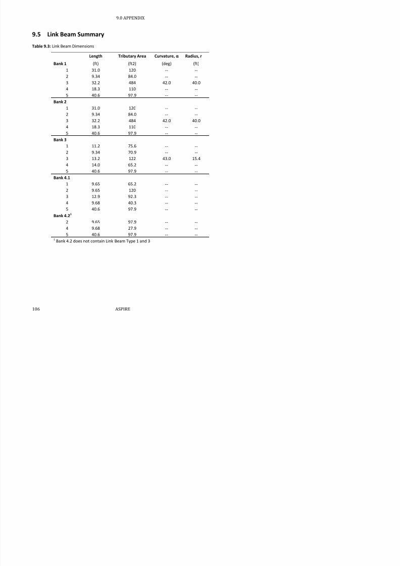
7/17/2019 Structural Design Project of Super Tall Building Chicago Spire
http://slidepdf.com/reader/full/structural-design-project-of-super-tall-building-chicago-spire 122/474
3 32.2 484 42.0 40.0
4 18.3 110 -- --
5 40.6 97.9 -- --
Bank 21 31.0 120 -- --
2 9.34 84.0 -- --
3 32.2 484 42.0 40.0
4 18.3 110 -- --
5 40.6 97.9 -- --
Bank 3
1 11.2 75.6 -- --
2 9.34 70.9 -- --
3 13.2 122 43.0 15.4
4 14.0 65.2 -- --
5 40.6 97.9 -- --
Bank 4.1
1 9.65 65.2 -- --
2 9.65 120 -- --
3 12.9 92.3 -- --
4 9.68 40.3 -- --
5 40.6 97.9 -- --
Bank 4.21
2 9.65 97.9 -- --
4 9.68 27.9 -- --
5 40.6 97.9 -- -- 1 Bank 4.2 does not contain Link Beam Type 1 and 3
9.0 APPENDIX
Table 9.4: Residential and Lobby Link Beam Summary
b hbar # nbar
stirrup
#
sstirrup
Bank 1 (in) (in) (in)
1 16 16 9 6 3 7.22 6 10 9 2 3 4.2
3 48 16 9 20 4 7.1
4 10 16 9 3 4 7.1

7/17/2019 Structural Design Project of Super Tall Building Chicago Spire
http://slidepdf.com/reader/full/structural-design-project-of-super-tall-building-chicago-spire 123/474
4 10 16 9 3 4 7.1
5 20 16 9 6 4 7.1
Bank 2
1 16 16 9 6 3 7.2
2 6 10 9 2 3 4.23 48 16 9 20 4 7.1
4 10 16 9 3 4 7.1
5 20 16 9 6 4 7.1
Bank 3
1 6 12 9 2 3 5.2
2 6 10 9 2 3 4.2
3 28 16 9 11 3 7.24 10 10 9 2 3 4.2
5 20 16 9 6 4 7.1
Bank 4.1
1 8 8 9 2 3 3.2
2 8 10 9 2 3 4.2
3 30 16 9 10 4 7.1
4 8 6 9 2 3 2.2
5 20 16 9 6 3 7.2
Bank 4.21
2 8 10 9 2 3 4.2
4 8 6 9 2 3 2.2
5 20 16 9 6 3 7.21 Bank 4.2 does not contain Link Beam Type 1 and 3
9.0 APPENDIX
Table 9.5: Mechanical Floor Link Beam Summary
b hbar # nbar stirrup #
sstirrup
Bank 1 (in) (in) (in)
1 22 16 9 6 3 7.22 8 10 9 2 3 4.2
3 72 16 9 20 4 7.1
4 12 16 9 3 4 7.1

7/17/2019 Structural Design Project of Super Tall Building Chicago Spire
http://slidepdf.com/reader/full/structural-design-project-of-super-tall-building-chicago-spire 124/474
5 24 16 9 6 4 7.1
Bank 2
1 22 16 9 6 3 7.2
2 8 10 9 2 3 4.2
3 72 16 9 20 4 7.1
4 12 16 9 3 4 7.1
5 24 16 9 6 4 7.1
Bank 3
1 10 10 9 2 3 4.2
2 8 10 9 2 3 4.2
3 48 16 9 11 3 7.2
4 10 10 9 2 3 4.2
5 24 16 9 6 4 7.1
Bank 4.1
1 10 8 9 2 3 3.2
2 10 10 9 2 3 4.2
3 12 10 9 10 3 4.2
4 8 8 9 2 3 3.2
5 24 16 9 6 3 7.2
Bank 4.21
2 8 10 9 2 3 4.2
4 6 8 9 2 3 3.2
5 24 16 9 6 3 7.21 Bank 4.2 does not contain Link Beam Type 1 and 3
9.0 APPENDIX
9.6 Beam Spans and Tributary Areas
Bank 1
Lobby and Mechanical Joist 1 Joist 2 Joist 3
Circumferential
Girder
Angled
Girder
Radial
Girder
Long
Cantilever
Short
Cantilever
Length ft 15.3 17.7 20.1 22.5 27.9 37.0 21.2 9.1
Tributary Area ft2 122.9 150.3 174.9 223.4 285.9 -- -- --

7/17/2019 Structural Design Project of Super Tall Building Chicago Spire
http://slidepdf.com/reader/full/structural-design-project-of-super-tall-building-chicago-spire 125/474
Residential
Length ft 15.7 19.1 -- 22.5 27.9 37.0 21.2 9.1
Tributary Area ft2 173.3 236.5 -- 258.6 285.9 -- -- --
Bank 2
Lobby and Mechanical Joist 1 Joist 2 Joist 3
Circumferential
Girder
Angled
Girder
Radial
Girder
Long
Cantilever
Short
Cantilever
Length ft 14.3 16.3 18.3 20.4 25.3 31.2 19.2 8.7
Tributary Area ft2 100.5 117.6 131.7 185.7 259.4 -- -- --
Residential
Length ft 14.9 17.7 -- 20.4 25.3 31.2 19.2 8.7
Tributary Area ft2 144.1 172.6 -- 210.5 259.3 -- -- --
Bank 3
Lobby and Mechanical Joist 1 Joist 2 Joist 3
Circumferential
Girder
Angled
Girder
Radial
Girder
Long
Cantilever
Short
Cantilever
Length ft 18.9 21.7 24.4 27.2 33.7 27.6 19.3 5.0
Tributary Area ft2 113.1 137.4 154.7 237.5 344.9 -- -- --
Residential
Length ft 18.9 23.1 -- 27.2 33.7 27.6 19.3 5.0
Tributary Area ft2 158.5 225.0 -- 281.2 344.9 -- -- --
Bank 4
Lobby Joist 1 Joist 2 Joist 3 CircumferentialGirder AngledGirder RadialGirder LongCantilever ShortCantilever
Length ft 18.9 21.7 24.4 27.2 33.7 27.6 19.3 5.0
Tributary Area ft2
113 1 137 4 154 7 237 5 344 9
9.0 APPENDIX
9.7 Slab and Decking Summary
Table 9.6: Decking and Slab Thickness Summary for Composite Beam System
Lobby Residential Mechanical
Properties 1-3 4 1 2 3 4
Type 1.5VL22 1.5VL22 1.5VL19 2VLI16 2VLI19 2VLI20 2VLI16

7/17/2019 Structural Design Project of Super Tall Building Chicago Spire
http://slidepdf.com/reader/full/structural-design-project-of-super-tall-building-chicago-spire 126/474
t 2.5 2.5 2.5 2.5 2.5 2.5 2.5
Rib Height 1.5 1.5 1.5 2 2 2 2
Rib Spacing 6 6 6 12 12 12 12
All decking uses 6x6 - W1.4xW1.4 shrinkage mesh
Table 9.7: Unfactored Dead Load for Composite Beam System
Floor Type DL
Lobby 32 psf
Residential 33 psf
Mechanical 39 psfIncludes weight of concrete and decking
9.0 APPENDIX
9.8 Composite Beam Summary
Table 9.8: Composite Beam Summary
Bank 1 Joist 1 Joist 2 Joist 3 Angled
Girder
Circumferential
Girder
Radial
Girder
Long
Cantilever
Short
CantileverLobby W12x14
(30)
W12x26
(70)
W12x35
(80)
W14x82
(110)
W16x31
(45)
W21x73
(75)
W24x306
(32)
W14x193
(19)
Residential W12x14
(16)
W12x22
(19)--
W14x53
(110)
W14x34
(90)
W14x61
(80)
W21x182
(32)
W21x101
(14)

7/17/2019 Structural Design Project of Super Tall Building Chicago Spire
http://slidepdf.com/reader/full/structural-design-project-of-super-tall-building-chicago-spire 127/474
(16) (19) (110) (90) (80) (32) (14)
Mechanical W14x22
(15)
W14x30
(17)
W16x36
(20)
W18x76
(81)
W16x50
(44)W14x730
1
W27x539
(32)
W24x176
(14)
Bank 2
Lobby W12x19
(56)
W12x14
(32)
W12x19
(36)
W14x61
(50)
W12x45
(80)
W21x50
(63)
W24x250
(29)
W18x175
(14)
Residential W12x16
(29)
W12x16
(35)--
W14x43
(50)
W14x26
(80)
W16x36
(27)
W21x166
(29)
W21x101
(14)
Mechanical W12x19
(14)
W12x22
(32)
W12x26
(36)
W16x67
(75)
W12x45
(40)W14x730
1
W27x539
(29)
W24x250
(14)
Bank 3
Lobby W12X16
(37)
W12X35
(86)
W12X40
(96)
W14X120
(134)
W12X65
(108)
W18x55
(83)
W24x192
(29)
W18x106
(8)
Residential W12X22
(74)
W12X35
(92)--
W14x82
(134)
W14x43
(108)
W16x40
(24)
W21x201
(29)
W18x46
(8)
Mechanical W14x22
(36)
W14x30
(42)
W14x38
(48)
W21x111
(66)
W21x55
(81)W14x730
1
W36x442
(29)
W21x166
(8)
Bank 4.1Lobby W12X16
(37)
W12X35
(86)
W12X40
(96)
W14X120
(134)
W12X65
(108)
W18x55
(67)
W24x370
(29)
W18x106
(8)
Residential W12 x 22
(39)
W12 x 30
(92)--
W14 x 74
(132)
W14 x38
(106)
W16x36
(24)
W24x176
(25)
W18x50
(8)
Bank 4.2
Residential W12x22
(39)
W12x30
(92) --
W18x60
(66)
W14 x38
(106)
W16x36
(24)
W24x176
(25)
W18x50
(8)
1 W14x730 are rotated girders at the mechanical floors
9.0 APPENDIX
9.9 Initial Gravity Design Column Comparison
Table 9.9: Initial Composite and Steel Column Comparison
Column 1 / 21 Column 3a/3b1
Steel2 Composite2 Steel2 Composite2
Bank Level Shape Shape Concrete2(in) Shape Shape
Concrete
(in)
4 145 W14x99 W4X13 10X12 -- -- --

7/17/2019 Structural Design Project of Super Tall Building Chicago Spire
http://slidepdf.com/reader/full/structural-design-project-of-super-tall-building-chicago-spire 128/474
5 99 3 0
4 134 W14x99 W8X35 14X22 -- -- --
4 123 W14x193 W14X90 22X26 -- -- --
4 113 W14x311 W14X193 24X28 -- -- --
3 100 W14x426 W14X342 24X28 -- -- --
3 87 W14x550 W14X500 24X28 -- -- --
3 75 W14x665 W14X550 30X32 -- -- --
2 64
Sq. Pl.
24x4.25 W14X730 30X32 W14x455 W14x132 30X30
2 52
Sq. Pl.
24x5.25 W14X730 38X40 W14x605 W14x500 30X30
2 41 Sq. Pl. 26x6 W14X730 48X48 W14x730 W14x730 30X30
1 29 Sq. Pl. 28x6 W14X730 56X58
Sq. Pl.
24x5 W14x730 40X40
1 17 Sq. Pl. 32x6 W14X730 64X64
Sq. Pl.
26x6 W14x730 50X50
1 5 Sq. Pl. 36x6 W27X539 68X70
Sq. Pl.
28x6 W14x665 60X60
1 Lobby -- W14X730 72X74 -- W14x665 60X62
1 Column 2 only applies to Bank 3 & 4. Column 3a/3b only applies to Bank 1 & 2.
2 Columns were sized for both steel and composite configurations and then the optimal design was chosen.
The grey text shows the shapes and dimensions not chosen.
9.0 APPENDIX
9.10 MIDAS Gen Gravity Loads
Table 9.10: MIDAS Gen Unfactored Gravity Loads (kips / node)
Floor Type1 Column 1 Column 2 Column 3a/bCore
(Total Load for
all core walls divided
by # radial girders)
SDL + DL LL
SDL +
DL LL
SDL
+ DL LL
SDL +
DL LL

7/17/2019 Structural Design Project of Super Tall Building Chicago Spire
http://slidepdf.com/reader/full/structural-design-project-of-super-tall-building-chicago-spire 129/474
1 L 0.0 0.0 0.0 0.0
2 L 5.4 0.0 5.4 0.0
3 L 5.4 0.0 5.4 0.0
4 L 5.4 0.0 5.4 0.05 L 96.2 35.3 96.2 35.3 36.4 32.1
6 R 96.2 35.3 96.2 35.3 36.4 32.1
7 R 96.2 35.3 96.2 35.3 36.4 32.1
8 R 96.2 35.3 96.2 35.3 36.4 32.1
9 R 96.2 35.3 96.2 35.3 36.4 32.1
10 R 96.2 35.3 96.2 35.3 36.4 32.1
11R
96.2 35.3 96.2 35.3 36.4 32.112 R 96.2 35.3 96.2 35.3 36.4 32.1
13 R 96.2 35.3 96.2 35.3 36.4 32.1
14 R 96.2 35.3 96.2 35.3 36.4 32.1
15 R 96.2 35.3 96.2 35.3 36.4 32.1
16 R 96.2 35.3 96.2 35.3 36.4 32.1
17 R 96.2 35.3 96.2 35.3 36.4 32.1
18 R 96.2 35.3 96.2 35.3 36.4 32.1
19 R 96.2 35.3 96.2 35.3 36.4 32.1
20 R 96.2 35.3 96.2 35.3 36.4 32.1
21 R 96.2 35.3 96.2 35.3 36.4 32.1
22 R 96.2 35.3 96.2 35.3 36.4 32.1
23 R 96.2 35.3 96.2 35.3 36.4 32.1
24 R 96.2 35.3 96.2 35.3 36.4 32.1
25 R 96.2 35.3 96.2 35.3 36.4 32.1
26 R 96.2 35.3 96.2 35.3 36.4 32.1
27 R 96.2 35.3 96.2 35.3 36.4 32.1
28 R 96.2 35.3 96.2 35.3 36.4 32.1
9.0 APPENDIX
Floor Type1 Column 1 Column 2 Column 3a/b
Core (Total Load for
all core walls divided
by # radial girders)
SDL + DL LL
SDL +
DL LL
SDL
+ DL LL
SDL +
DL LL
36 R 96.2 35.3 96.2 35.3 36.4 32.1
37 R 96.2 35.3 96.2 35.3 36.4 32.1
38 M 56.3 249.0 56.3 249.0 25.1 92.3
39 M 5.4 0.0 5.4 0.0 9.7 16.6

7/17/2019 Structural Design Project of Super Tall Building Chicago Spire
http://slidepdf.com/reader/full/structural-design-project-of-super-tall-building-chicago-spire 130/474
40 L 75.8 80.0 75.8 80.0 33.1 47.8
41 R 74.6 27.2 74.6 27.2 32.7 30.1
42 R 74.6 27.2 74.6 27.2 32.7 30.1
43 R 74.6 27.2 74.6 27.2 32.7 30.1
44 R 74.6 27.2 74.6 27.2 32.7 30.1
45 R 74.6 27.2 74.6 27.2 32.7 30.1
46 R 74.6 27.2 74.6 27.2 32.7 30.1
47 R 74.6 27.2 74.6 27.2 32.7 30.1
48 R 74.6 27.2 74.6 27.2 32.7 30.1
49 R 74.6 27.2 74.6 27.2 32.7 30.1
50 R 74.6 27.2 74.6 27.2 32.7 30.1
51 R 74.6 27.2 74.6 27.2 32.7 30.1
52 R 74.6 27.2 74.6 27.2 32.7 30.1
53 R 74.6 27.2 74.6 27.2 32.7 30.1
54 R 74.6 27.2 74.6 27.2 32.7 30.1
55 R 74.6 27.2 74.6 27.2 32.7 30.1
56 R 74.6 27.2 74.6 27.2 32.7 30.1
57 R 74.6 27.2 74.6 27.2 32.7 30.158 R 74.6 27.2 74.6 27.2 32.7 30.1
59 R 74.6 27.2 74.6 27.2 32.7 30.1
60 R 74.6 27.2 74.6 27.2 32.7 30.1
61 R 74.6 27.2 74.6 27.2 32.7 30.1
62 R 74.6 27.2 74.6 27.2 32.7 30.1
63 R 74.6 27.2 74.6 27.2 32.7 30.1
64 R 74.6 27.2 74.6 27.2 32.7 30.165 R 74.6 27.2 74.6 27.2 32.7 30.1
66 R 74.6 27.2 74.6 27.2 32.7 30.1
67 R 74 6 27 2 74 6 27 2 32 7 30 1
9.0 APPENDIX
Floor Type1 Column 1 Column 2 Column 3a/b
Core (Total Load for
all core walls divided
by # radial girders)
SDL + DL LL
SDL +
DL LL
SDL
+ DL LL
SDL +
DL LL
74 L 57.9 61.5 2.2 0.0 57.9 61.5 24.3 33.2
75 R 57.0 20.9 57.0 20.9 24.0 18.8
76 R 57.0 20.9 57.0 20.9 24.0 18.8
77 R 57.0 20.9 57.0 20.9 24.0 18.8

7/17/2019 Structural Design Project of Super Tall Building Chicago Spire
http://slidepdf.com/reader/full/structural-design-project-of-super-tall-building-chicago-spire 131/474
78 R 57.0 20.9 57.0 20.9 24.0 18.8
79 R 57.0 20.9 57.0 20.9 24.0 18.8
80 R 57.0 20.9 57.0 20.9 24.0 18.8
81 R 57.0 20.9 57.0 20.9 24.0 18.8
82 R 57.0 20.9 57.0 20.9 24.0 18.8
83 R 57.0 20.9 57.0 20.9 24.0 18.8
84 R 57.0 20.9 57.0 20.9 24.0 18.8
85 R 57.0 20.9 57.0 20.9 24.0 18.8
86 R 57.0 20.9 57.0 20.9 24.0 18.8
87 R 57.0 20.9 57.0 20.9 24.0 18.8
88 R 57.0 20.9 57.0 20.9 24.0 18.889 R 57.0 20.9 57.0 20.9 24.0 18.8
90 R 57.0 20.9 57.0 20.9 24.0 18.8
91 R 57.0 20.9 57.0 20.9 24.0 18.8
92 R 57.0 20.9 57.0 20.9 24.0 18.8
93 R 57.0 20.9 57.0 20.9 24.0 18.8
94 R 57.0 20.9 57.0 20.9 24.0 18.8
95 R 57.0 20.9 57.0 20.9 24.0 18.896 R 57.0 20.9 57.0 20.9 24.0 18.8
97 R 57.0 20.9 57.0 20.9 24.0 18.8
98 R 57.0 20.9 57.0 20.9 24.0 18.8
99 R 57.0 20.9 57.0 20.9 24.0 18.8
100 R 57.0 20.9 57.0 20.9 24.0 18.8
101 R 57.0 20.9 57.0 20.9 24.0 18.8
102 R 57.0 20.9 57.0 20.9 24.0 18.8103 R 57.0 20.9 57.0 20.9 24.0 18.8
104 R 57.0 20.9 57.0 20.9 24.0 18.8
105 R 57 0 20 9 57 0 20 9 24 0 18 8
9.0 APPENDIX
Floor Type1 Column 1 Column 2 Column 3a/b
Core (Total Load for
all core walls divided
by # radial girders)
SDL + DL LL
SDL +
DL LL
SDL
+ DL LL
SDL +
DL LL
112 R 63.7 22.8 63.7 22.8 23.7 23.3
113 R 63.7 22.8 63.7 22.8 23.7 23.3
114 R 63.7 22.8 63.7 22.8 23.7 23.3
115 R 63.7 22.8 63.7 22.8 23.7 23.3

7/17/2019 Structural Design Project of Super Tall Building Chicago Spire
http://slidepdf.com/reader/full/structural-design-project-of-super-tall-building-chicago-spire 132/474
116 R 63.7 22.8 63.7 22.8 23.7 23.3
117 R 63.7 22.8 63.7 22.8 23.7 23.3
118 R 63.7 22.8 63.7 22.8 23.7 23.3
119 R 63.7 22.8 63.7 22.8 23.7 23.3
120 R 63.7 22.8 63.7 22.8 23.7 23.3
121 R 63.7 22.8 63.7 22.8 23.7 23.3
122 R 63.7 22.8 63.7 22.8 23.7 23.3
123 R 63.7 22.8 63.7 22.8 23.7 23.3
124 R 54.6 19.4 54.6 19.4 25.3 34.4
125 R 54.6 19.4 54.6 19.4 25.3 34.4
126 R 54.6 19.4 54.6 19.4 25.3 34.4127 R 54.6 19.4 54.6 19.4 25.3 34.4
128 R 54.6 19.4 54.6 19.4 25.3 34.4
129 R 54.6 19.4 54.6 19.4 25.3 34.4
130 R 54.6 19.4 54.6 19.4 25.3 34.4
131 R 54.6 19.4 54.6 19.4 25.3 34.4
132 R 54.6 19.4 54.6 19.4 25.3 34.4
133 R 54.6 19.4 54.6 19.4 25.3 34.4134 R 54.6 19.4 54.6 19.4 25.3 34.4
135 R 54.6 19.4 54.6 19.4 25.3 34.4
136 R 54.6 19.4 54.6 19.4 25.3 34.4
137 R 54.6 19.4 54.6 19.4 25.3 34.4
138 R 54.6 19.4 54.6 19.4 25.3 34.4
139 R 54.6 19.4 54.6 19.4 25.3 34.4
140 R 54.6 19.4 54.6 19.4 25.3 34.4141 R 54.6 19.4 54.6 19.4 25.3 34.4
142 R 54.6 19.4 54.6 19.4 25.3 34.4
143 R 54 6 19 4 54 6 19 4 25 3 34 4
9.0 APPENDIX
9.11 Column Validation Summary
Table 9.11: Composite and Steel Shapes for Lateral Design Column Validation
Column 1 / 21 Column 3a/3b
Bank Level Steel ShapeConcrete
(in.)Steel % Shape
Concrete
(in.) Steel %
4 134 W14x233 -- -- -- -- --
4 123 W14x370 -- -- -- -- --

7/17/2019 Structural Design Project of Super Tall Building Chicago Spire
http://slidepdf.com/reader/full/structural-design-project-of-super-tall-building-chicago-spire 133/474
4 113 W14x550 -- -- -- -- --
3 100 W18x35 22x20 2.3% -- -- --
3 87 W18x50 22x22 3.0% -- -- --
3 75 W21x111 26x24 5.2% -- -- --
2 64 W24x146 30x26 5.5% W24x162 30x26 6.1%
2 52 W24x131 30x26 4.9% W24x146 30x26 5.5%
2 41 W24x162 30x28 5.7% W24x162 30x28 5.7%
1 29 W36x361 42x38 6.6% W36x330 42x34 6.8%
1 17 W36x330 42x34 6.8% W36x330 42x34 6.8%
1 5 W36x330 42x34 6.8% W36x330 42x34 6.8%
1 Lobby W40x324 46x38 5.5% W40x324 46x38 5.5%1 Column 2 only applies to Bank 3 & 4. Column 3a/3b only applies to Bank 1 & 2
9.0 APPENDIX
9.12 MIDAS Sensitivity Analyses
Steel built-ups shown in Table 9.12 were used in the MIDAS model for several sensitivity analyses to test
the axial discontinuity and lateral deflection of the model.
Table 9.12: Built-up Steel and Concrete Properties
Column Nomenclature As (in2) Ag (in
2) Gross dimension (in)
BU1 768 1600 40x40
BU2 640 1296 36x36

7/17/2019 Structural Design Project of Super Tall Building Chicago Spire
http://slidepdf.com/reader/full/structural-design-project-of-super-tall-building-chicago-spire 134/474
BU2 640 1296 36x36
BU3 476 1024 32x32
BU4 364 784 28x28
Three different sensitivity analyses were performed and are summarized in Table 9.13. The built-
ups in Banks 1-3 were changed and the larger built-up test resulted in less deflection. The
discontinuity results for the test are shown in Figure 9.1. Core wall thickness in Bank 3 was also
tested (Figure 9.2).
The sensitivity analysis for the effects of belt trusses and outriggers kept the core wall sizes to a
uniform one foot. While the results are relative to this unrealistic design, they show patterns in belt
truss and outrigger functionality given sizing and general existence.
Ultimately, the sensitivity analysis showed that the large belt truss and outrigger members were
causing large load shedding from the exterior columns to the core. Additionally, the large, built-up
steel shapes encased in concrete reduced drift and eliminated the tension forces from the original
column design.
9.0 APPENDIX
Table 9.13: Sensitivity Analyses Element Properties
Core Wall
Thickness by
Bank (ft)
Belt
Truss Outrigger
Vertical Column Size by Bank
Δmax 1 2 3 4 1 2 3
4
111-122 123-133 134-145
Built Up
10 8 4 3.3 W14x730 W14x730 BU1 /BU2 BU3 BU4 W14x550 W14x370 W14x233 5.34
10 8 4 3 3 W14x730 W14x730 BU1 BU2 BU2 W14x550 W14x370 W14x233 5 09

7/17/2019 Structural Design Project of Super Tall Building Chicago Spire
http://slidepdf.com/reader/full/structural-design-project-of-super-tall-building-chicago-spire 135/474
10 8 4 3.3 W14x730 W14x730 BU1 BU2 BU2 W14x550 W14x370 W14x233 5.09
Core Size
10 8 6 2 W14x730 W14x730 BU1 BU2 BU2 W14x550 W14x370 W14x233 5.06
10 8 4 2 W14x730 W14x730 BU1 BU2 BU2 W14x550 W14x370 W14x233 5.16
10 8 2 2 W14x730 W14x730 BU1 BU2 BU2 W14x550 W14x370 W14x233 5.37
Belt Truss and Outrigger
1 1 1 1 W14x730 W14x730 BU1 BU2 BU2 W14x550 W14x370 W14x233 8.1
1 1 1 1 W14x730 None BU1 BU2 BU2 W14x550 W14x370 W14x233 8.34
1 1 1 1 None None BU1 BU2 BU2 W14x550 W14x370 W14x233 9.0
9.0 APPENDIX

7/17/2019 Structural Design Project of Super Tall Building Chicago Spire
http://slidepdf.com/reader/full/structural-design-project-of-super-tall-building-chicago-spire 136/474
Figure 9.2: Core Wall Thickness Sensitivity Results to Dead Load
Figure 9.3: Belt Truss and Outrigger Sensitivity
9.0 APPENDIX
9.13 Core Wall Reinforcement
Table 9.14: Core Wall Reinforcement Details
Horizontal Shear Vertical Shear Flexural
Thickness Bar Size Spacing Bar Size Spacing Bar Size Spacing
(ft) (in) (in) (in)
Bank 1
NS 7 18 6 10 12 10 12
EW 7 18 6 10 12 10 12

7/17/2019 Structural Design Project of Super Tall Building Chicago Spire
http://slidepdf.com/reader/full/structural-design-project-of-super-tall-building-chicago-spire 137/474
EW 7 18 6 10 12 10 12
Bank 2
NS 4 18 8 18 9 18 9
EW 4 18 9 18 10 18 10
Bank 3
NS 3 14 10 8 16 8 16
EW 3 14 9 7 12 7 12
Bank 4
4.1 2 18 7 6 14 6 14
4.2 2 8 17 6 14 6 14
9.0 APPENDIX
9.14 Creep and Shrinkage
9.14.1
Hand Calculations

7/17/2019 Structural Design Project of Super Tall Building Chicago Spire
http://slidepdf.com/reader/full/structural-design-project-of-super-tall-building-chicago-spire 138/474
9.0 APPENDIX

7/17/2019 Structural Design Project of Super Tall Building Chicago Spire
http://slidepdf.com/reader/full/structural-design-project-of-super-tall-building-chicago-spire 139/474
9.0 APPENDIX

7/17/2019 Structural Design Project of Super Tall Building Chicago Spire
http://slidepdf.com/reader/full/structural-design-project-of-super-tall-building-chicago-spire 140/474
9.0 APPENDIX
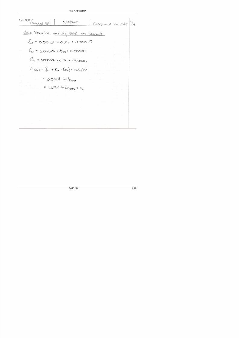
7/17/2019 Structural Design Project of Super Tall Building Chicago Spire
http://slidepdf.com/reader/full/structural-design-project-of-super-tall-building-chicago-spire 141/474
9.0 APPENDIX
9.14.2 Supplementary Materials
Table 9.15: Concrete Core Properties
Bank 1 2 3 4
Radius Ro 40 38 36 26 ft
Thickness t 8 6 4 3.33 ft
Total Volume / Floor Vc 23886 17417 11280 6721 ft3
Total Weight/Floor Wc 3822 2787 1805 1075 kips
Total Area/Floor A 1810 1319 855 509 ft2

7/17/2019 Structural Design Project of Super Tall Building Chicago Spire
http://slidepdf.com/reader/full/structural-design-project-of-super-tall-building-chicago-spire 142/474
Total Area/Floor At 1810 1319 855 509 ft
# of Columns 21 21 14 14
Steel Area As 2873 10187 715 123 in2
Area per core "column" 86 63 61 36 ft
2
Self-Weight per core "column" 182 133 129 77 kips
Table 9.16: Steel Deflection Summary
Floors Deflectionper Floor
Deformation perFloor Segment
Sum of Floor SegmentDeformations
(in) (in) (in)
Lobby 0.979 0.979 0.98
5-16 0.077 0.921 1.90
17-28 0.067 0.805 2.71
29-39 0.057 0.631 3.34
40-51 0.049 0.590 3.93
52-63 0.041 0.492 4.42
64-73 0.034 0.335 4.75
74-86 0.054 0.702 5.46
87-99 0.042 0.546 6.00
100-110 0.031 0.340 6.34
111-122 0.021 0.251 6.59
123-133 0.012 0.131 6.72
134-145 0.004 0.045 6.77
9.0 APPENDIX
Table 9.17: Humidity Data for Chicago
National Climatic Data for Humidity in Chicago, IL
(All Values in %) Morning Afternoon
January 78 70
February 78 67
March 79 63
April 77 58
May 77 57

7/17/2019 Structural Design Project of Super Tall Building Chicago Spire
http://slidepdf.com/reader/full/structural-design-project-of-super-tall-building-chicago-spire 143/474
June 79 58
July 82 60
August 86 61
September 85 61
October 81 59
November 80 66
December 80 71
Average 80.17 62.58
Average Humidity Between Morning and Afternoon
71.4%
Table 9.18: Concrete Reinforcement Data
Bank 1 2 3 4Core Radius Ro 40 38 36 26 ft
Core Thickness tc 8 6 4 3.33 ft
Core Circumference 251 239 226 163 ft
Rebar Spacing (in) 12 9 12 14 in
Rebar Spacing (ft) s 1 0.75 1 1.1667 ft
Bar Size 10 18 8 6
Number of Bars per Row nb 251 318 226 140
Stee Area per Bar Asb 1.27 4 0.79 0.44 in2
9.0 APPENDIX
Table 9.19: 20 Year Concrete Deflection
Deformation
per Floor
Deformation per
Floor Segment
Sum of Floor Segment
Deformations
(in) (in) (in)
0.371 0.371 0.37
0.088 1.054 1.43
0.078 0.937 2.36
0.068 0.752 3.11
0.005 0.057 3.17

7/17/2019 Structural Design Project of Super Tall Building Chicago Spire
http://slidepdf.com/reader/full/structural-design-project-of-super-tall-building-chicago-spire 144/474
0.004 0.049 3.22
0.004 0.035 3.26
0.220 2.857 6.11
0.175 2.274 8.39
0.133 1.468 9.86
0.715 8.585 18.44
0.419 4.611 23.05
0.145 1.737 24.79
9.14.3 Analysis Procedure for Creep and Shrinkage
Quantifying the amount of displacement in both the columns and core is essential for constructing a
serviceable building. If there is a large difference between the displacement of the columns and the
core that is not accounted for, floors will begin to slant over time and cause uncomfortable
situations for occupants.
The quantification of displacements depends on a multitude of factors, requiring an in-depth
analysis.
Step 1: Determine the expected loads on the concrete in question. The necessary loads are the DL,
SDL, the sustained portion of LL on the building. These loads will need to be broken up by floor
because the amount of creep is highly dependent on the amount of load and the sequence in which
it is applied.
Step 2: Create a construction schedule to determine when the concrete will be loaded with which
amount of load. For our skyscraper, as each of the 150 floors is added vertically, an additional load
9.0 APPENDIX
Step 4: Conduct laboratory tests to determine ultimate creep and shrinkage strains for the concrete
mixture specified in Step 3. The data from these tests will be used as initial values for creep and
shrinkage strains that will then be modified by calculated correction factors.
Step 5: Evaluate the geometries of structural elements. Correction factors based on the geometries
of the elements will be applied to the creep and shrinkage values calculated in order to obtain an
accurate estimate. Important geometric considerations are the height of the element as well as its
surface-to-volume ratio.
Step 6: Calculate the expected creep and shrinkage coefficients for loading, construction timing,
mixture composition properties and geometries per GL2000 Method from ACI 209 2R 27 These

7/17/2019 Structural Design Project of Super Tall Building Chicago Spire
http://slidepdf.com/reader/full/structural-design-project-of-super-tall-building-chicago-spire 145/474
mixture composition properties, and geometries per GL2000 Method from ACI 209.2R-27. These
coefficients are then used to factor the ultimate creep and shrinkage strain values obtained from
laboratory tests to calculate the final expected displacements.
Step 7: Compare the newly calculated strain values for the column and core concrete to determine
the anticipated differential displacement. The differences will be used to modify the column and
core heights to account for the eventual differential displacement in the concrete.
Assumptions from GL2000 Method:
The method is defined for concretes with mean compressive strengths less than 11,890 psi. Thecore compressive strength is 14,000 psi, but it is assumed that since mix details are not provided
this method still provides the best estimate for creep and shrinkage strains.
Type III cement was used to provide the highest initial strength gain, which led to the smallest
ultimate deformation of the core. Per this type of cement, values for the s and k parameters were
0.13 and 1.15, respectively.
In order to determine the correction term for humidity average data was taken from the National
Climatic Data Center for Chicago, IL. The average relative humidity over the year was found to be
0.71.
The time when curing stops and the time when subsequent loading is added were both taken to be
four days. Because of this, the correction term for drying occurring before loading does not affect
the creep coefficient.

7/17/2019 Structural Design Project of Super Tall Building Chicago Spire
http://slidepdf.com/reader/full/structural-design-project-of-super-tall-building-chicago-spire 146/474
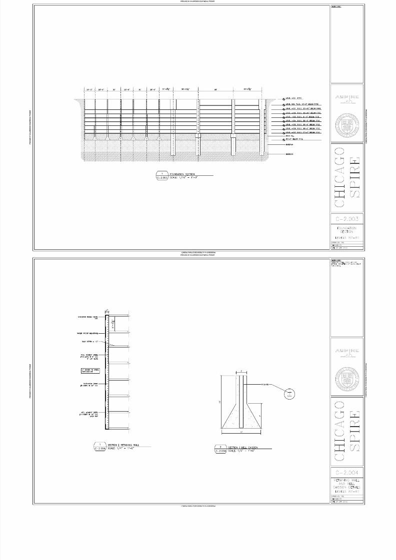
7/17/2019 Structural Design Project of Super Tall Building Chicago Spire
http://slidepdf.com/reader/full/structural-design-project-of-super-tall-building-chicago-spire 147/474

7/17/2019 Structural Design Project of Super Tall Building Chicago Spire
http://slidepdf.com/reader/full/structural-design-project-of-super-tall-building-chicago-spire 148/474

7/17/2019 Structural Design Project of Super Tall Building Chicago Spire
http://slidepdf.com/reader/full/structural-design-project-of-super-tall-building-chicago-spire 149/474
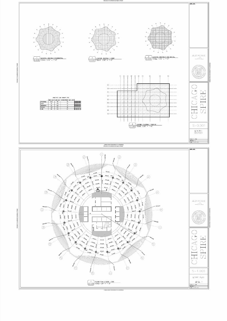
7/17/2019 Structural Design Project of Super Tall Building Chicago Spire
http://slidepdf.com/reader/full/structural-design-project-of-super-tall-building-chicago-spire 150/474

7/17/2019 Structural Design Project of Super Tall Building Chicago Spire
http://slidepdf.com/reader/full/structural-design-project-of-super-tall-building-chicago-spire 151/474

7/17/2019 Structural Design Project of Super Tall Building Chicago Spire
http://slidepdf.com/reader/full/structural-design-project-of-super-tall-building-chicago-spire 152/474

7/17/2019 Structural Design Project of Super Tall Building Chicago Spire
http://slidepdf.com/reader/full/structural-design-project-of-super-tall-building-chicago-spire 153/474

7/17/2019 Structural Design Project of Super Tall Building Chicago Spire
http://slidepdf.com/reader/full/structural-design-project-of-super-tall-building-chicago-spire 154/474

7/17/2019 Structural Design Project of Super Tall Building Chicago Spire
http://slidepdf.com/reader/full/structural-design-project-of-super-tall-building-chicago-spire 155/474

7/17/2019 Structural Design Project of Super Tall Building Chicago Spire
http://slidepdf.com/reader/full/structural-design-project-of-super-tall-building-chicago-spire 156/474

7/17/2019 Structural Design Project of Super Tall Building Chicago Spire
http://slidepdf.com/reader/full/structural-design-project-of-super-tall-building-chicago-spire 157/474

7/17/2019 Structural Design Project of Super Tall Building Chicago Spire
http://slidepdf.com/reader/full/structural-design-project-of-super-tall-building-chicago-spire 158/474

7/17/2019 Structural Design Project of Super Tall Building Chicago Spire
http://slidepdf.com/reader/full/structural-design-project-of-super-tall-building-chicago-spire 159/474

7/17/2019 Structural Design Project of Super Tall Building Chicago Spire
http://slidepdf.com/reader/full/structural-design-project-of-super-tall-building-chicago-spire 160/474

7/17/2019 Structural Design Project of Super Tall Building Chicago Spire
http://slidepdf.com/reader/full/structural-design-project-of-super-tall-building-chicago-spire 161/474

7/17/2019 Structural Design Project of Super Tall Building Chicago Spire
http://slidepdf.com/reader/full/structural-design-project-of-super-tall-building-chicago-spire 162/474

7/17/2019 Structural Design Project of Super Tall Building Chicago Spire
http://slidepdf.com/reader/full/structural-design-project-of-super-tall-building-chicago-spire 163/474

7/17/2019 Structural Design Project of Super Tall Building Chicago Spire
http://slidepdf.com/reader/full/structural-design-project-of-super-tall-building-chicago-spire 164/474
7/17/2019 Structural Design Project of Super Tall Building Chicago Spire
http://slidepdf.com/reader/full/structural-design-project-of-super-tall-building-chicago-spire 165/474

7/17/2019 Structural Design Project of Super Tall Building Chicago Spire
http://slidepdf.com/reader/full/structural-design-project-of-super-tall-building-chicago-spire 166/474

7/17/2019 Structural Design Project of Super Tall Building Chicago Spire
http://slidepdf.com/reader/full/structural-design-project-of-super-tall-building-chicago-spire 167/474

7/17/2019 Structural Design Project of Super Tall Building Chicago Spire
http://slidepdf.com/reader/full/structural-design-project-of-super-tall-building-chicago-spire 168/474

7/17/2019 Structural Design Project of Super Tall Building Chicago Spire
http://slidepdf.com/reader/full/structural-design-project-of-super-tall-building-chicago-spire 169/474

7/17/2019 Structural Design Project of Super Tall Building Chicago Spire
http://slidepdf.com/reader/full/structural-design-project-of-super-tall-building-chicago-spire 170/474

7/17/2019 Structural Design Project of Super Tall Building Chicago Spire
http://slidepdf.com/reader/full/structural-design-project-of-super-tall-building-chicago-spire 171/474

7/17/2019 Structural Design Project of Super Tall Building Chicago Spire
http://slidepdf.com/reader/full/structural-design-project-of-super-tall-building-chicago-spire 172/474

7/17/2019 Structural Design Project of Super Tall Building Chicago Spire
http://slidepdf.com/reader/full/structural-design-project-of-super-tall-building-chicago-spire 173/474

7/17/2019 Structural Design Project of Super Tall Building Chicago Spire
http://slidepdf.com/reader/full/structural-design-project-of-super-tall-building-chicago-spire 174/474

7/17/2019 Structural Design Project of Super Tall Building Chicago Spire
http://slidepdf.com/reader/full/structural-design-project-of-super-tall-building-chicago-spire 175/474

7/17/2019 Structural Design Project of Super Tall Building Chicago Spire
http://slidepdf.com/reader/full/structural-design-project-of-super-tall-building-chicago-spire 176/474

7/17/2019 Structural Design Project of Super Tall Building Chicago Spire
http://slidepdf.com/reader/full/structural-design-project-of-super-tall-building-chicago-spire 177/474

7/17/2019 Structural Design Project of Super Tall Building Chicago Spire
http://slidepdf.com/reader/full/structural-design-project-of-super-tall-building-chicago-spire 178/474

7/17/2019 Structural Design Project of Super Tall Building Chicago Spire
http://slidepdf.com/reader/full/structural-design-project-of-super-tall-building-chicago-spire 179/474

7/17/2019 Structural Design Project of Super Tall Building Chicago Spire
http://slidepdf.com/reader/full/structural-design-project-of-super-tall-building-chicago-spire 180/474
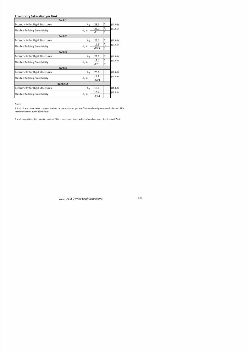
7/17/2019 Structural Design Project of Super Tall Building Chicago Spire
http://slidepdf.com/reader/full/structural-design-project-of-super-tall-building-chicago-spire 181/474
11.0 Calculation Book

7/17/2019 Structural Design Project of Super Tall Building Chicago Spire
http://slidepdf.com/reader/full/structural-design-project-of-super-tall-building-chicago-spire 182/474
2011 – 2012
ASPIREMaster of Engineering
Structural Design Project
Table of Contents
1.0 General Notes ................................................................................................................ 1
1.1 List of Variables .......................................................................................................... 2
1.2 Color Key Explanation ................................................................................................ 7
2.0 Preliminary Load Analysis ..............................................................................................
2.1 Gra!ity "esi#n Loads .................................................................................................. $
2.2 %ind Load Cal&'lations ............................................................................................ 10
2.2.1 A(CE 7 %ind Load Cal&'lations......................................................................... 11
2.2.2 %ind )'nnel "ata ............................................................................................. 1$
2 * (eismi& Cal&'lations 2*

7/17/2019 Structural Design Project of Super Tall Building Chicago Spire
http://slidepdf.com/reader/full/structural-design-project-of-super-tall-building-chicago-spire 183/474
2.* (eismi& Cal&'lations ................................................................................................. 2*
2.*.1 (eismi& %ei#+t Cal&'lation ............................................................................... 2,
2.*.2 (eismi& Load Cal&'lations ...................................................................... ........... 2$
*.0 Gra!ity "esi#n .............................................................................................................. *2
*.1 )rib'tary Areas ......................................................................................................... ***.2 Core Area
*.2.1 Con&rete (lab "esi#n ........................................................................................ *$
*.2.2 Lin- eam "esi#n .............................................................................................. ,/
*.* loor Area ................................................................................................................. /1
*.*.1 Composite "e&-in# ........................................................................................... /2
*.*.2 Composite eam "esi#n ................................................................................... ,
*.*.* Vibration Analysis ............................................................................................. $*
*., Col'mns .................................................................................................................... $$
*.,.1 Col'mn Load )a-edon ................................................................................. 100
*.,.2 Composite Col'mn "esi#n .............................................................................. 11,
*.,.* (teel Col'mn "esi#n ....................................................................................... 11
,./ Core ebar "esi#n .................................................................................................. 1*1
,./.1 "esi#n of Core ebar for Verti&al and 8ori9ontal (+ear ................................ 1*2
,./.2 "esi#n of Core ebar for lex'ral Capa&ity .................................................... 1*,
,./.* an- , (tron# Axis endin# ............................................................................ 1*
,. Ener#y 3et+od 6ptimi9ation ................................................................................. 1/
,..1 6ptimi9ation Cal&'lations ............................................................................... 1/
,..2 esi9in# of 'ilt:'p 3embers ......................................................................... 11
/.0 Conne&tion "esi#n ..................................................................................................... 12
/.1 )ypi&al Conne&tions
/.1.1 %elded Col'mn (pli&e .................................................................................... 1*

7/17/2019 Structural Design Project of Super Tall Building Chicago Spire
http://slidepdf.com/reader/full/structural-design-project-of-super-tall-building-chicago-spire 184/474
/.1.2 loor ;oist to adial Girder Conne&tion .......................................................... 1
/.1.* Girder to Col'mn Conne&tions ....................................................................... 171
/.1., 8(( to Cantile!er Conne&tion ......................................................................... 177
/.1./ adial Girder to Con&rete Core ....................................................................... 10
/.2 ase of 3e#a:Col'mn Conne&tion ......................................................................... 1$
/.2.1 3e#a:Col'mn to Caisson Conne&tion ............................................................ 1$0
/.2.2 Caisson Cap 3oment einfor&ement ............................................................. 1$,
/.* 6'tri##er Conne&tions ........................................................................................... 1$
/.*.1 ottom of 6'tri##er to Col'mn Conne&tion .................................................. 1$7
/.*.2 )op of 6'tri##er to Core ................................................................................. 1$$
.0 o'ndation "esi#n ..................................................................................................... 21$
.1 etainin# %all ........................................................................................................ 220
.1.1 (oil Profile ....................................................................................................... 221
.1.2 Effe&ti!e Press're ........................................................................................... 222
.1.* etainin# %all "esi#n ..................................................................................... 22,
.*.1 Aba='s Analysis of Caissons ........................................................................... 2/1
.*.2 3e#a:Col'mn Caisson "esi#n......................................................................... 2/*
.*.* in# eam "esi#n ........................................................................................... 2//
.*., Core Caisson "esi#n ........................................................................................ 2/7
.*./ Caisson ebar .................................................................................................. 2/$
7.0 Creep and (+rin-a#e .................................................................................................. 20
7.1 (teel Col'mn "eformation ..................................................................................... 21
7.1.1 (teel Col'mn Properties and Loads ................................................................ 22
7.1.2 (teel Col'mn "eformation Cal&'lations ......................................................... 2*
7.2 Con&rete Core "eformation ................................................................................... 2/

7/17/2019 Structural Design Project of Super Tall Building Chicago Spire
http://slidepdf.com/reader/full/structural-design-project-of-super-tall-building-chicago-spire 185/474
7.2.1 Con&rete Core Properties and Loads .............................................................. 2
7.2.2 Con&rete Core "eformation Cal&'lations ....................................................... 27
.0 eferen&es ................................................................................................................. 2$
.1 Ener#y:ased "esi#n of Lateral (ystems by %illiam . a-er ............................... 270
.2 Geote&+ni&al eport for t+e C+i&a#o (pire ............................................................ 27,
1.0 General Notes
1.1 List of Variables 2
1.2 Color Key Explanation 7
The calculation book is a compilation of all the calculations performed for the design of The
Chicago Spire. The calculations shown are the final design calculations performed for eachdeliverable. Hand calculations and spreadsheets are included in the calculation book. The
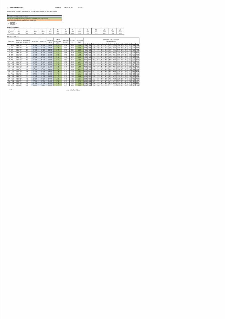
7/17/2019 Structural Design Project of Super Tall Building Chicago Spire
http://slidepdf.com/reader/full/structural-design-project-of-super-tall-building-chicago-spire 186/474
spreadsheets included are demonstrative of the many calculations performed (Ex
Spreadsheet containing the design of a single column is attached. However! the
spreadsheet was used to design columns on multiple floors."
a = Whitney Stress Block Theory depth of compression zone
a = distance from support face to 1st bolts, in
A = torque coefficient
ao/ = acceleration limit for !ibrational analysis
ap/ = peak acceleration for !ibrational analysis
Ase," = effecti!e cross sectional area of sinle bolt, in#
A!/s = steel area/spacin ratio in#/in
A$ = area of %%%%%%%%%%%% &concrete, rebar, net area, etc', in#
b = beam/column (idth, in
b = eccentricity of cur!ature, in
B = anular t(ist coefficient
beff = effecti!e (idth of slab section, in
bf = flane (idth of a steel section, in
B ) = effecti!e panel (idth, inbo = punchin shear perimeter, in
1.1 List of Variables

7/17/2019 Structural Design Project of Super Tall Building Chicago Spire
http://slidepdf.com/reader/full/structural-design-project-of-super-tall-building-chicago-spire 187/474
* = concrete compressi!e force, lbs
c = concrete co!er, in
c = turbulence intensity factor
*+ = instantaneous center of rotation at the centroid of the bolt roup
*1 = effecti!e riidity
*all = allo(able compression, ksi
*app = applied compression, ksi*b = beam bendin coefficient
*c = centerline circumfrence, ft
*col = distance from concrete compression face to neutral a$is
cb = !ertical centroid of bolt roup, in
c = location of factored tensile force, in
* ) = effecti!e (idth factor
*( = (arpin constant, in-
d = structural depth, in &ote. for steel sections, this is the member depth'd = depth belo( rade &ft'
= (eld size, in
deff = effecti!e concrete depth, in
dist$ = distance, in
) = transformed )oist moment of inertia, in0/ft
= dead load
dm = moment arm, in
s = transformed slab moment of inertia, in0
/ftu = pretension multiplier
d = diameter of &bolt column rebar shear stud etc' in
f+c,a! = a!erae compressi!e strenth of concrete, ksi
f+c4comp = compressi!e stress in concrete, ksi
f comp = allo(able compressi!e stress, ksi
5cr = fle$ural bucklin stress, ksi
5 = factored dead load
5e = elastic critical bucklin stress, ksi
5277 = electrode strenth, ksi5lim = elastic bucklin limit
5 = factored li!e load
58s = factored seismic moment
58W = factored (ind moment
f n = natural frequency of the floor, 9z
f r = allo(able tension stress, ksi
f s = stress in concrete reinforcin steel
5s = force in concrete reinforcin steel, kip5S = factor of safety
f l l l k

7/17/2019 Structural Design Project of Super Tall Building Chicago Spire
http://slidepdf.com/reader/full/structural-design-project-of-super-tall-building-chicago-spire 188/474
f t = lateral tensile stress, ksi
5u = specified ultimate strenth of steel, ksi
5( = nominal strenth of (eld, ksi
5y = specified minimum yield strenth of steel section, ksi
5yr = specified minimum yield stress of reinforcin bars, ksi
= acceleration due to ra!ity, in/sec#
: = shear modulus, ksih = beam/slab depth, in
h = floor to floor heiht, ft
heff = effecti!e embedment depth of anchor, in
hf = factor for fillers
3c = moment of inertia of core, in0
3c = moment of inertia of the concrete section, in0
3comp = moment of inertia of the composite section, in0
3eff = moment of inertia for post4composite deflection, in0
3o = moment of inertia of column, in0
3s = moment of inertia of steel shape, in0
3sr = moment of inertia of reinforcin bars, in0
3t = transformed moment of inertia, in0
3$ = moment of inertia of stron a$is, in0
3y = moment of inertia of (eak a$is, in0
; = polar moment of inertia, in0
< = distance from flane to (eb (eld, in
< = effecti!e lenth factor
lc = clear distance bt(n ede of hole and ede of ad)acent hole, in
l c ede = clear distance, in dir> of force, bet(een ede of hole and ede of material, in
l c int = clear distance, in dir> of force, bet(een ede of hole and ede ad)acent hole, in
lcbtm = clear distance bt(n ede of hole and ede of material for bottom bolts, in
ld = embedment lenth, in
eh = horizontal ede distance, in
e! = !ertical ede distance, in
e$ = effecti!e lenth on stron a$is, ftey = effecti!e lenth on (eak a$is, ft
ird = (idth at irder, in
= li!e load
o = total open lenth in core, ft
o = openin lenth in core, ft
out = (idth at outrier, in
p = lenth of plate, in
( = lenth of (eld, inl ( = Whitmore Section (idth, in
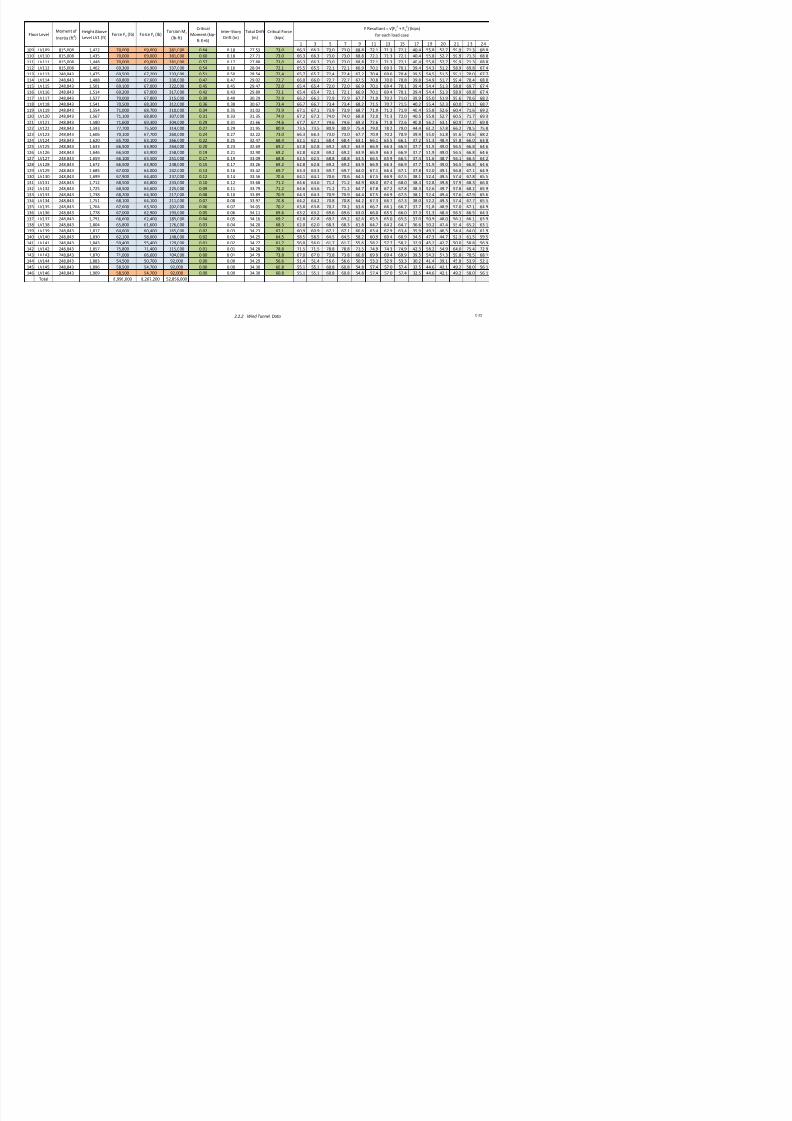
7/17/2019 Structural Design Project of Super Tall Building Chicago Spire
http://slidepdf.com/reader/full/structural-design-project-of-super-tall-building-chicago-spire 189/474
8 = applied moment
8n = allo(able moment
8post = post4composite moment, kip4ft
8pre = pre4composite moment, kip4ft
8s = seismic moment, kip4ft
8u = ma$imum applied moment
8( = (ind moment, kip4ft
= bearin lenth, in
n = number of %%%%%% &number of bolts, shear studs, etc'
n = ratio bet(een steel and concrete modulus of elasticity
n = dynamic modular ratio
= tension force &from A*3?1@4@', kips
n = nominal tension strenth, kips
$ = nominal tension strenth of a roup of anchors/hooked bolt, lbs
= perimeter of column, in = total load, kips
cp = outer perimeter of cross section, in
e = 2uler bucklin load, kips
= applied a$ial load
h = perimeter of torsion reinforcin, in
n = allo(able column a$ial load
o = e$citation for !ibrational analysis, lbs
o = nominal a$ial compressi!e strenth (ithout consideration of lenth effects, kipsp = ankine+s passi!e earth pressure, kips
f lid ll
u = load at connection, kips
r$ = radius of %%%%% &column, bolt, etc', in
r$ = radius of yration &stron', in
ry = radius of yration &(eak', in
s = spacin, in
Sc = section modulus for compression, in?
Smin = minimum required section modulus, in?
Ss = section modulus of steel shape, in?
Stens = section modulus for tension, in?
S$ = section modulus &stron', in?
Sy = section modulus &(eak', in?
T = clear space, in
T = distance bet(een (eld centers, in
Tapp = applied tension, ksi
Tb = min> fastener tension, kips
tf = thickness of flane of steel section, in
Tn = nominal tensile capacity, kips

7/17/2019 Structural Design Project of Super Tall Building Chicago Spire
http://slidepdf.com/reader/full/structural-design-project-of-super-tall-building-chicago-spire 190/474
Tth = threshold torsional moment, kip4ft
Tu = ma$imum tension force, kips
Tu = ma$imum applied torsional moment, kip4ft
t( = thickness of (eb of steel section, in
t$ = thickness of %%%%%%% &concrete, plate, (all, etc', in
D = shear la factor
Dbs = block shear rupture reduction coefficient
Dbs = reduction coefficient
" = shear force, kips
" = basic (ind speed, mph
"6h = ad)usted horizontal shear, kips
"6h = partial composite action horizontal shear, kips
"c = allo(able shear in concrete, kips
"c = concrete !olume, ft?
"cp = ominal pryout strenth &roup', kips
"n = total shear capacity, kips
"sa = ominal strenth in shear, kips
"th = theoretical concrete !olume, ft?/ft
#
"u = ma$imum applied shear, kips
( = distributed load, plf
W = (eiht supported, lbf
(a = anle (idth, in
Wc = core (all self4(eiht, kip
(c = (eiht of concrete per unit !olume, pcf
G = anle of cur!ature, radians
G = anle of backfill abo!e (all, radians
H = modal dampin ratio for !ibrational analysis
H1 = concrete stress block coefficient
I = deflection, in
Jcu = concrete ultimate compressi!e strain
Js = strain in concrete reinforcin steel
Jys = steel yield strain
K = anle of t(ist, radians
L = modification factor reflectin the reduced mechanical properties of liht(eiht concrete
M = mean slip coefficient
Nactual = density of the steel in slab
Nbal =
O = ?>101PQ#-P0
Nc = density of concrete, pcf
Nclay = density of clay, psf
N = steel ratio
Ns = spiral reinforcement ratio
density of steel at (hich a balanced failure bet(een concrete crushin and steel yieldin in tension

7/17/2019 Structural Design Project of Super Tall Building Chicago Spire
http://slidepdf.com/reader/full/structural-design-project-of-super-tall-building-chicago-spire 191/474
Nsr = reinforcement ration for continuous lonitudinal reinforcin, A sr/A
Ns( = beam self (eiht density, lb/ft
Ract = actual stress per caisson, ksi
Rall = allo(able stress, ksi
Rc = net compression stress, ksi
Rc = allo(able stress in concrete, ksi
Rr = allo(able stress in rock, ksi
Rt = net tensile stress, ksi
= strenth reduction factor
$ = factored allo(able strenth &moment, a$ial, shear, bearin, etc>'
$ = modification factor for anchor bolts
U = anle of friction for soil, radians
1.2 Color Key Explanation
Color Key: User Input
Constant/Previous Calc.
Calc/Lookup
Yes Passes Check
No Fails Check
The yello$ cell inicates a user input. The user shoul input values "or the spreasheet to
calculate the results.
The gray cell inicates a constant or a previous calculation. %hen it is a previous
calculation& it is irectly re"erencing the cell $here the calculation $as per"or#e. 'othconstants an previous calculations are consiere inactive cells.

7/17/2019 Structural Design Project of Super Tall Building Chicago Spire
http://slidepdf.com/reader/full/structural-design-project-of-super-tall-building-chicago-spire 192/474
The green cell inicates that a check is !eing per"or#e an the conitions are satis"ie.
The re cell inicates that a check is !eing per"or#e an the conitions are not satis"ie.
The $hite cell inicates a calculation or a value that is o!taine via lookup. (n e)a#ple o" a
lookup $oul !e the various section properties o" a %*shape "or a speci"ic shape.
2.0 Preliminary Load Analysis
2.1
Gravity Design Loads 9
2.2 Wind Load Calculations 10
2.2.1
ASCE Wind Load Calculations 11
2.2.2 Wind !unnel Data 19
2."
Seismic Calculations
2.".1
Seismic Weig#t Calculation 2$
2.".2
Seismic Load Calculations 29

7/17/2019 Structural Design Project of Super Tall Building Chicago Spire
http://slidepdf.com/reader/full/structural-design-project-of-super-tall-building-chicago-spire 193/474
2.1 Gravity Design Loads
Loads taken from ASCE 7
Dead LoadSuperimposed
Dead Load
Live Load
(psf) (psf) (psf)
Decking and Slab 32
Assembl Areas (lobbies) !""
Acoustical fiber board !
#E$ Duct Allo%ance !"
Ceramic or &uarr tile (! !'2 in) on ! in mortar bed *
Total 32 +7 !""Decking and Slab 33
$rivate rooms and corridors serving t,em "
L o b b y
Typical Floor

7/17/2019 Structural Design Project of Super Tall Building Chicago Spire
http://slidepdf.com/reader/full/structural-design-project-of-super-tall-building-chicago-spire 194/474
$rivate rooms and corridors serving t,em "
$artition -alls !+
Acoustical fiber board !
Ceramic or &uarr tile (3' in) on ! in mortar bed 23
#E$ Duct Allo%ance !"
Total 33 3 ++Decking and Slab 3.
Cat%alks "
#ac,ine Space 2""
#E$ Duct Allo%ance !"
Total 3. !" 2"
Slab (!+" pcf / !2 in) !+"
0arages (passenger ve,icles onl) "#E$ Duct Allo%ance !"
Cement finis, (!1in) on stone1concrete fill 32
Total !+" 2 "
Slab (!!" pcf / * in) ++
Total ++ C o r e
R e s i d e n t i a l
M e c h a n i c a l
P a r k i n g
2.2 Wind Load Calculations
2.2.1 ASCE 7 Wind Load Calculations 11
2.2.2 Wind Tunnel Data 19

7/17/2019 Structural Design Project of Super Tall Building Chicago Spire
http://slidepdf.com/reader/full/structural-design-project-of-super-tall-building-chicago-spire 195/474
2.2.1 ASCE 7 Wind Load Calculations Created by: JLB,CJB,JAC,DBL 3/10/2012
Definition of Variables from ASCE 7 Chapter 26
Basic Wind Speed V 120 mph 2!"#$
Wind Directi%na&ity 'act%r (d 0")# 2!"!$
*+p%sre Cate-%ry D 2!".$3Sec%nd st Speed *+p%nent 11"# 2!"1$
ean 4%r&y Wind Speed 5%6er La6 *+p%nent 0"11 2!"1$
=e9erence t%%& that ca&c&ates 6ind &%ads 9%r stren-th acc%rdin- t% ASC* .10 and then c%mpares these a&es
t% 6ind tnne& data 9r%m =WD8 tests" See ass%ciated macthcad 9i&e and =WD8 9i&e 9%r inpt a&es"

7/17/2019 Structural Design Project of Super Tall Building Chicago Spire
http://slidepdf.com/reader/full/structural-design-project-of-super-tall-building-chicago-spire 196/474
ean 4%r&y Wind Speed 'act%r b 0")0 2!"1$
7rb&ence 8ntensity 'act%r c 0"1# 2!"1$
8nte-ra& Len-th Sca&e 'act%r & !#0 9t 2!"1$
8nte-ra& Len-th Sca&e 5%6er La6 *+p%nent 0"13 2!"1$
;%mina& 4ei-ht %9 Atm%sphere B%ndary Layer <- .00 9t 2!"1$
7%p%-raphic 'act%r (<t 1"00 2!")"2$
=i-idity '&e+ib&e
5ea> 'act%r 9%r Bac>-r%nd =esp%nse -? 3"@0 2!""#$
5ea> 'act%r 9%r =es%nant =esp%nse -V 3"@0 2!""#$
5ea> 'act%r 9%r Wind =esp%nse -= 3"@ 2!"11$
;mber %9 St%ries ; 1#0
5eri%d 7 1#"0 secBi&din- ;atra& 'reency n1 0"0. 4<
Bi&din- Width B 1#0 9t
Bi&din- Len-th L 1#0 9t
ean =%%9 4ei-ht h 2,000 9t
*ia&ent 4ei-ht 1,200 9t 2!""@$
Dampin- =ati% 0"02
ean 4%r&y Wind Speed V< 210 mph 2!"1!$8nte-ra& Len-th Sca&e %9 7rb&ence L< 1,01 9t 2!"$
Definition of Variables from ASCE 7 Chapter 26 cont!
= Ca&c&ati%n 8ntermediate Va&es =n 0"21 2!"13$
Eh 2"2 2!""#$
=h 0"2) 2!"1#a$
EB 0"22 2!""#$
=B 0"). 2!"1#a$
EL 0".3 2!""#$
=L 0"!# 2!"1#a$
=es%nant =esp%nse 'act%r = 1"@. 2!"12$
8ntensity %9 7rb&ence 8< 0"0) 2!".$
Bac>-r%nd =esp%nse 'act%r ? 0".1 2!")$
st *99ect 'act%r 9 1"12 2!""#$

7/17/2019 Structural Design Project of Super Tall Building Chicago Spire
http://slidepdf.com/reader/full/structural-design-project-of-super-tall-building-chicago-spire 197/474
*nc&%sre c&assi9icati%n *nc&%sed
0"1)
0"1)Cpi 2!"111$
5r%dct %9 8nterna& 5ressre C%e99icient and st*99ect
'act%r
Calculated Values from ASCE 7 Chapter 26
Basic Wind Speed V 120 mph (26.5)
Wind Directionality Factor Kd 0.5 (26.6)
!"pos#re $ate%ory D (26.&)
'opo%raphic Factor Kt 1.00 (26..2)
#st !**ect Factor * 1.12 (26.+.5)
!nclos#re $lassi*ication !nclosed0.1 Fi% (26.11,1)
,0.1
-,Second #st Speed !"ponent 11.5 Fi% (26.+,1)
/ominal ei%ht o* tmosphere Bo#ndary ayer % &00 Fi% (26.+,1)
Calculated Values from ASCE 7 Chapter 27
Wall Pressure Coefficients
3rod#ct o* ;nternal 3ress#re $oe**icient and #st,
!**ect Factor$pi

7/17/2019 Structural Design Project of Super Tall Building Chicago Spire
http://slidepdf.com/reader/full/structural-design-project-of-super-tall-building-chicago-spire 198/474
3lan en%th to Width 4atio B 1.00 Fi% (2&.,1)
Wind7ard Wall 3ress#re $oe**icient $p 0.0 Fi% (2&.,1)
ee7ard Wall 3ress#re $oe**icient $p ,0.50 Fi% (2&.,1)
Side Wall 3ress#re $oe**icient $p ,0.&0 Fi% (2&.,1)
ee7ard Velocity 3ress#re 1 8h 6-.0 ps* (2&..1)
Building Dimensions
oriontal Dimension , Ban9 1 B" 1+ *t
oriontal Dimension , Ban9 2 B" 1& *t
oriontal Dimension , Ban9 - B" 15- *t
oriontal Dimension , Ban9 B" 1-- *toriontal Dimension , Ban9 .2 B" 120 *t
Story ei%ht h 1-.2 *t
Eccentricity Calculation Values
Shear $enter and $enter o* :ass !ccentridity e4 0.0 *t (2&..6)
;ntensity o* '#r<#lence ; 0.0 (26.+,&)
3ea9 Factor *or Bac9%ro#nd 4esponse %= -.0 (26.+.5)
3 9 F * Wi d 4 - +
Eccentricity Calculation per Ban
!ccentricity *or 4i%id Str#ct#res e= 2.- *t (2&.,)
21.1 *t (2&..6)
,21.1 *t
!ccentricity *or 4i%id Str#ct#res e= 26.1 *t (2&.,)
1+.5 *t (2&..6)
,1+.5 *t
!ccentricity *or 4i%id Str#ct#res e= 2-.0 *t (2&.,)
1&.1 *t (2&..6)
,1&.1 *t
!ccentricity *or 4i%id Str#ct#res e= 20.0 (2&.,)
1.+ (2&..6)
1 +
Ban !
Ban "
Ban 2
e"> ey
e"> eyFle"i<le B#ildin% !ccentricity
Fle"i<le B#ildin% !ccentricity
Ban $
e"> ey
e"> ey
Fle"i<le B#ildin% !ccentricity
Fle"i<le B#ildin% !ccentricity
7/17/2019 Structural Design Project of Super Tall Building Chicago Spire
http://slidepdf.com/reader/full/structural-design-project-of-super-tall-building-chicago-spire 199/474
,1.+
!ccentricity *or 4i%id Str#ct#res e= 1.0 (2&.,)
1-. (2&..6)
,1-.
/otes
2 ;n all calc#lations> the ne%ati?e ?al#e o* $pi is #sed to %et lar%er ?al#es o* 7ind press#re. See Section 2&.,2
Ban !#2
1 Both 8h and 8i are ta9en conser?ati?ely to <e the ma"im#m 8 ?al#e *rom 7ind7ard press#re calc#lations. 'his
ma"im#m occ#rs at the 150th le?el
y
e"> eyFle"i<le B#ildin% !ccentricity
ASCE Ch 27 Wind Load Cases
Floor
(relative
to
ground)
Height
(relative
to
ground)
Width of
Buidling
Velocity
PressureExposure
Coefficien
t
Velocity
Pressure
Windward
Pressure
eeward
Pressure
!ide Wall
Pressure
Windward
Force
eeward
Force
!ideWall
Force
" # w $# %# p p p f f f PW& PW' P& P' FW& FW' F& F' F& F'
ine
oad
&'
ft ft psf psf psf psf l* l* l* psf psf psf psf l* l* l* l* l* l* +ipsft
, , -./ - 01 02 314 30. .50/6 32/51. 346056 02 02 314 314 .50/6 .50/6 32/51. 32/51. -45,12 -45,12 --
- -0 -.. - 01 02 314 30. .5104 32/2-2 3/4604 02 02 314 314 .5104 .5104 32/2-2 32/2-2 -4264/ -4264/ --
1 15 -.. - 05 0. 314 30. /4/-/ 32/4,0 3/4604 0. 0. 314 314 /4/-/ /4/-/ 32/4,0 32/4,0 -2401- -2401- -1
0 4, -.. - 0. 4- 314 30. -,-550 32/1/, 3/4604 4- 4- 314 314 -,-550 -,-550 32/1/, 32/1/, -5,/20 -5,/20 - 1
4 20 -.6 - 4, 40 314 30. -,5566 32/-66 3/4604 40 40 314 314 -,5566 -,5566 32/-66 32/-66 -52.24 -52.24 - 0
2 55 -.6 - 41 42 314 30. --,5.2 32/,52 3/4604 42 42 314 314 --,5.2 --,5.2 32/,52 32/,52 -5/62, -5/62, - 0
5 6/ -.5 - 40 45 314 30. --4,04 32./21 3/4604 45 45 314 314 --4,04 --4,04 32./21 32./21 -61/.5 -61/.5 - 0
6 /1 -.5 - 44 4. 314 30. --5/-, 32..4, 3/4604 4. 4. 314 314 --5/-, --5/-, 32..4, 32..4, -6264/ -6264/ - 0. -,2 -.5 - 42 4/ 314 30. --/415 32.616 3/4604 4/ 4/ 314 314 --/415 --/415 32.616 32.616 -6.-20 -6.-20 - 4
/ --/ -.2 - 45 2, 314 30. -1-552 32.5-2 3/4604 2, 2, 314 314 -1-552 -1-552 32.5-2 32.5-2 -.,16/ -.,16/ - 4
-, -01 -.2 1 46 2- 314 30. -10566 32.2,1 3/4604 2- 2- 314 314 -10566 -10566 32.2,1 32.2,1 -.1-6/ -.1-6/ -4
7 7 7 7 7 7 7 7 7 7 7 7 7 7 7 7 7 7 7 7 7 7
-05 -6/- -,, 1 50 5. 314 30. ./066 30-5-6 35,165 5. 5. 314 314 ./066 ./066 30-5-6 30-5-6 -1,//4 -1,//4 /
-06 -.,4 /6 1 50 5. 314 30. .50/. 30,250 35,165 5. 5. 314 314 .50/. .50/. 30,250 30,250 --5/5- --5/5- /
-0. -.-6 /0 1 50 5. 314 30. .041, 31/2,/ 35,165 5. 5. 314 314 .041, .041, 31/2,/ 31/2,/ --1/1/ --1/1/ /
-0/ -.0, /, 1 50 5. 314 30. .,44- 31.422 35,165 5. 5. 314 314 .,44- .,44- 31.422 31.422 -,../5 -,../5 .
-4, -.40 .6 1 50 5. 314 30. 66451 3164,1 35,165 5. 5. 314 314 66451 66451 3164,1 3164,1 -,4.50 -,4.50 .
-4- -.26 .0 1 50 5. 314 30. 644.0 31504. 35,165 5. 5. 314 314 644.0 644.0 31504. 31504. -,,.0- -,,.0- .
-41 -.6, ., 1 50 5. 314 30. 6-2,4 3121/4 35,165 5. 5. 314 314 6-2,4 6-2,4 3121/4 3121/4 /56/. /56/. 6
-40 -..0 66 1 50 5. 314 30. 5.212 31414, 35,165 5. 5. 314 314 5.212 5.212 31414, 31414, /1652 /1652 6
-44 -./5 60 1 50 5. 314 30. 52245 310-.6 35,165 5. 5. 314 314 52245 52245 310-.6 310-.6 ..600 ..600 6
-42 -/,/ 6, 1 50 5. 314 30. 51250 311-0- 35,165 5. 5. 314 314 51250 51250 311-0- 311-0- .45/4 .45/4 5
8esign Wind oad
Case - 8esign Wind oad Case -

7/17/2019 Structural Design Project of Super Tall Building Chicago Spire
http://slidepdf.com/reader/full/structural-design-project-of-super-tall-building-chicago-spire 200/474
2.2.1 ASCE 7 Wind Load CalculationsC-15
ASCE Ch 27 Wind Load Cases
Floor
(relative
to
ground)
" 962PW& 962PW' 9 62P& 9 62P' :; 962FW& 962FW' 962F& 962F' :; 962F& 962F' 962PW& 962PW' 962P& 962P' 962FW& 962FW' 962F& 962F' 962F& 962F'
psf psf psf psf +3ftft l* l* l* l* +3ft l* l* psf psf psf psf l* l* l* l* l* l*
, 15 15 3-. 3-. 01 546/. 546/. 34461- 34461- 6/.2/ -,/2-/ -,/2-/ 15 15 3-. 3-. 546/. 546/. 34461- 34461- -,/2-/ -,/2-/
- 15 15 3-. 3-. 01 54562 54562 344505 344505 6/6,/ -,/0-1 -,/0-1 15 15 3-. 3-. 54562 54562 344505 344505 -,/0-1 -,/0-1
1 1/ 1/ 3-. 3-. 40 6--./ 6--./ 344221 344221 -,2/24 --264- --264- 1/ 1/ 3-. 3-. 6--./ 6--./ 344221 344221 --264- --264-
0 0- 0- 3-. 3-. 2- 65146 65146 34445. 34445. -154-, -1,6-2 -1,6-2 0- 0- 3-. 3-. 65146 65146 34445. 34445. -1,6-2 -1,6-2
4 01 01 3-. 3-. 2. .,,,. .,,,. 3440.0 3440.0 -4-6,4 -140/- -140/- 01 01 3-. 3-. .,,,. .,,,. 3440.0 3440.0 -140/- -140/-
2 04 04 3-. 3-. 50 .0,-4 .0,-4 3441// 3441// -20//6 -160-1 -160-1 04 04 3-. 3-. .0,-4 .0,-4 3441// 3441// -160-1 -160-1
5 02 02 3-. 3-. 56 .2215 .2215 3441-4 3441-4 -54014 -1/64, -1/64, 02 02 3-. 3-. .2215 .2215 3441-4 3441-4 -1/64, -1/64,
6 05 05 3-. 3-. 6- .65.1 .65.1 344-0, 344-0, -6010. -0-.-1 -0-.-1 05 05 3-. 3-. .65.1 .65.1 344-0, 344-0, -0-.-1 -0-.-1. 06 06 3-. 3-. 64 ./25/ ./25/ 344,42 344,42 -.-,.- -005-2 -005-2 06 06 3-. 3-. ./25/ ./25/ 344,42 344,42 -005-2 -005-2
/ 06 06 3-. 3-. 66 /-14. /-14. 340/5- 340/5- -..,/2 -021,/ -021,/ 06 06 3-. 3-. /-14. /-14. 340/5- 340/5- -021,/ -021,/
-, 0. 0. 3-. 3-. ., /162. /162. 340.65 340.65 -/4404 -05504 -05504 0. 0. 3-. 3-. /162. /162. 340.65 340.65 -05504 -05504
7 7 7 7 7 7 7 7 7 7 7 7 7 7 7 7 7 7 7 7 7 7 7
-05 2- 2- 3-. 3-. /1 56,00 56,00 3106-1 3106-1 -1-2-5 /,642 /,642 2- 2- 3-. 3-. 56,00 56,00 3106-1 3106-1 /,642 /,642
-06 2- 2- 3-. 3-. /1 546// 546// 311/11 311/11 --6455 .661- .661- 2- 2- 3-. 3-. 546// 546// 311/11 311/11 .661- .661-
-0. 2- 2- 3-. 3-. .0 51252 51252 311-01 311-01 -,100, .45/6 .45/6 2- 2- 3-. 3-. 51252 51252 311-01 311-01 .45/6 .45/6
-0/ 2- 2- 3-. 3-. .0 5,00- 5,00- 31-041 31-041 /.565 .-561 .-561 2- 2- 3-. 3-. 5,00- 5,00- 31-041 31-041 .-561 .-561
-4, 2- 2- 3-. 3-. .0 2.,/5 2.,/5 31,22- 31,22- /2,11 6.54. 6.54. 2- 2- 3-. 3-. 2.,/5 2.,/5 31,22- 31,22- 6.54. 6.54.
-4- 2- 2- 3-. 3-. .0 22.51 22.51 3-/65- 3-/65- /-05. 62510 62510 2- 2- 3-. 3-. 22.51 22.51 3-/65- 3-/65- 62510 62510
-41 2- 2- 3-. 3-. .0 2051. 2051. 3-./6- 3-./6- .66-4 612// 612// 2- 2- 3-. 3-. 2051. 2051. 3-./6- 3-./6- 612// 612//
-40 2- 2- 3-. 3-. .0 2-0/4 2-0/4 3-.-., 3-.-., .4,2/ 5/264 5/264 2- 2- 3-. 3-. 2-0/4 2-0/4 3-.-., 3-.-., 5/264 5/264
-44 2- 2- 3-. 3-. .0 4/-5, 4/-5, 3-60/, 3-60/, .,4,2 5522, 5522, 2- 2- 3-. 3-. 4/-5, 4/-5, 3-60/, 3-60/, 5522, 5522,
-42 2- 2- 3-. 3-. -0- 45/11 45/11 3-52/. 3-52/. -1,5-. 5021- 5021- 2- 2- 3-. 3-. 45/11 45/11 3-52/. 3-52/. 5021- 5021-
8esign Wind oad Case 1 8esign Wind oad Case 1 8esign Wind oad Case 0 8esign Wind oad Case 0

7/17/2019 Structural Design Project of Super Tall Building Chicago Spire
http://slidepdf.com/reader/full/structural-design-project-of-super-tall-building-chicago-spire 201/474
2.2.1 ASCE 7 Wind Load Calculations C-16
ASCE Ch 27 Wind Load Cases
Floor
(relative
to
ground)
" 9250PW& 9250PW' 9250P& 9250P' :; 9250FW& 9250FW' 9250F& 9250F' :; F& F'
psf psf psf psf +3ftft l* l* l* l* l* l* l*
, 1, 1, 3-4 3-4 4. 4.54- 4.54- 30026, 30026, --/./5 .11-1 .11-1
- 1, 1, 3-4 3-4 4. 4.22, 4.22, 3002,6 3002,6 --/55/ .1,26 .1,26
1 11 11 3-4 3-4 54 2040/ 2040/ 300444 300444 -2/,60 .5..0 .5..0
0 10 10 3-4 3-4 66 26105 26105 3000., 3000., -./6.0 /,5-6 /,5-6
4 14 14 3-4 3-4 .5 5,,2/ 5,,2/ 3000-6 3000-6 1-1644 /0065 /0065
2 12 12 3-4 3-4 /4 510-5 510-5 300124 300124 10-1,, /225/ /225/
5 15 15 3-4 3-4 -,- 541,- 541,- 300-/, 300-/, 1456,2 /60/- /60/-
6 16 16 3-4 3-4 -,5 52.1, 52.1, 300-16 300-16 15,,.. /./46 /./46. 1. 1. 3-4 3-4 --- 56106 56106 300,50 300,50 16-.50 -,,0,, -,,0,,
/ 1. 1. 3-4 3-4 --5 5.4/6 5.4/6 300,,, 300,,, 1.10/0 -,-4/6 -,-4/6
-, 1/ 1/ 3-4 3-4 -1, 5/50, 5/50, 301/06 301/06 1/-/-- -,1256 -,1256
7 7 7 7 7 7 7 7 7 7 7 7 7
-05 0. 0. 3-4 3-4 -0/ 2,0-/ 2,0-/ 3-6.,, 3-6.,, -.1405 5.-1, 5.-1,
-06 0. 0. 3-4 3-4 -0/ 4.541 4.541 3-61,6 3-61,6 -65025 52.4/ 52.4/
-0. 0. 0. 3-4 3-4 -0/ 45/52 45/52 3-55-4 3-55-4 -6,162 5026/ 5026/
-0/ 0. 0. 3-4 3-4 -12 421.. 421.. 3-5,1, 3-5,1, -4.-45 5-0,. 5-0,.
-4, 0. 0. 3-4 3-4 -12 405-- 405-- 3-2416 3-2416 -4155, 2/,0. 2/,0.
-4- 0. 0. 3-4 3-4 -12 4-/04 4-/04 3-4.04 3-4.04 -06-60 2565. 2565.
-41 0. 0. 3-4 3-4 -12 4,126 4,126 3-414- 3-414- -0-5.6 244/6 244/6
-40 0. 0. 3-4 3-4 -12 0.2., 0.2., 3-0546 3-0546 -151,- 21116 21116
-44 0. 0. 3-4 3-4 -12 05/,0 05/,0 3-0,24 3-0,24 -1,6-2 4//26 4//26
-42 0. 0. 3-4 3-4 -12 02110 02110 3-145, 3-145, --211- 465.0 465.0
8esign Wind oad Case 4 8esign Wind oad Case 4
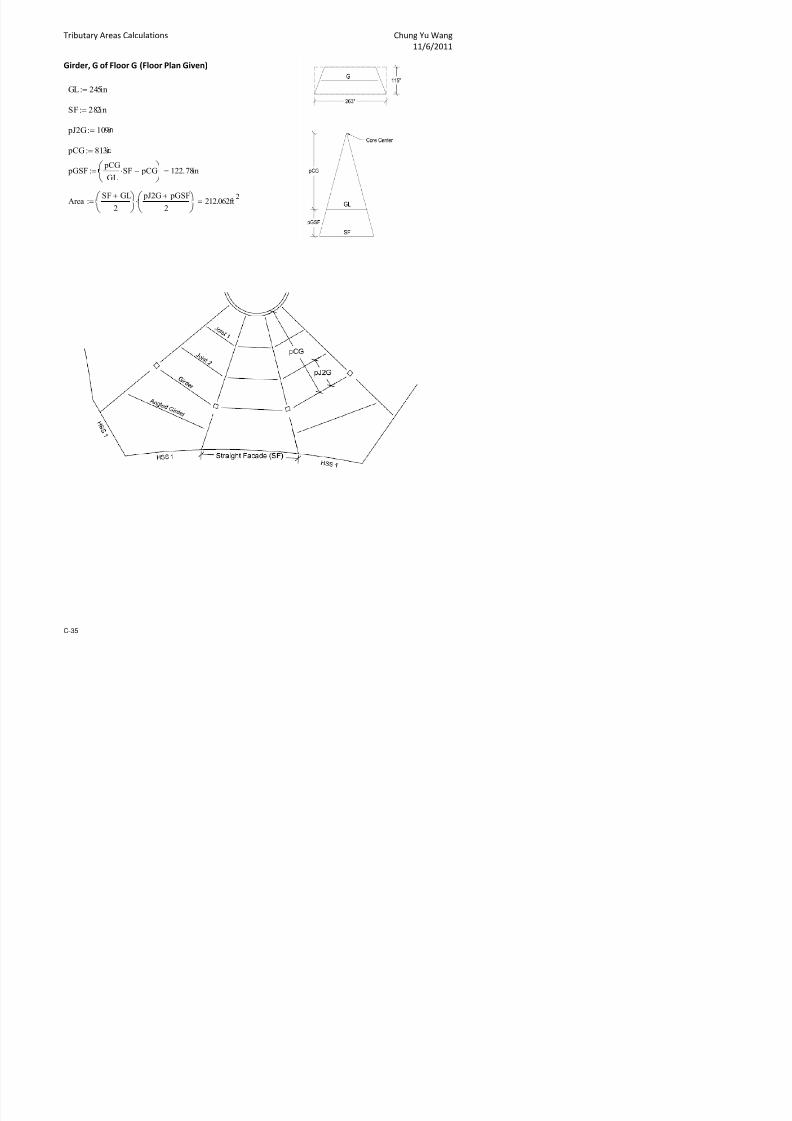
7/17/2019 Structural Design Project of Super Tall Building Chicago Spire
http://slidepdf.com/reader/full/structural-design-project-of-super-tall-building-chicago-spire 202/474
2.2.1 ASCE 7 Wind Load CalculationsC-17
Case 1 Loads (lb) Case 2 Loads (lb) Case 3 Loads (lb)
02 1 44 / 0 21 4 4/ 31 40 1 45 31 40 14 5 154005 154005 3-.1402 3-.1402 0126., 154005 154005 3-.1402 3-.1402
6,4/, 6,4/, 34.54/ 34.54/ 21.56 21.56 3054.6 3054.6 52-25 21.56 21.56 3054.6 3054.6
66605 66605 34.54/ 34.54/ 2.0,1 2.0,1 3054.6 3054.6 .5664 2.0,1 2.0,1 3054.6 3054.6
.04-. .04-. 34.54/ 34.54/ 51250 51250 3054.6 3054.6 -,0610 51250 51250 3054.6 3054.6
.65/. .65/. 34.54/ 34.54/ 52664 52664 3054.6 3054.6 --54/0 52664 52664 3054.6 3054.6
/--56 /--56 34.54/ 34.54/ 5.062 5.062 3054.6 3054.6 -15.4- 5.062 5.062 3054.6 3054.6
/4-,4 /4-,4 34.54/ 34.54/ 6,26. 6,26. 3054.6 3054.6 -025,2 6,26. 6,26. 3054.6 3054.6
/5551 /5551 34.54/ 34.54/ 614/6 614/6 3054.6 3054.6 -40102 614/6 614/6 3054.6 3054.6
/./01 /./01 34.54/ 34.54/ 64-// 64-// 3054.6 3054.6 -2,,,5 64-// 64-// 3054.6 3054.6
-, , /. , - ,, / ., 34 . 54 / 3 4. 5 4/ 62602 62602 3054.6 3054.6 -25--5 62602 62602 3054.6 3054.6
-,1.4. -,1.4. 34.54/ 34.54/ 66-05 66-05 3054.6 3054.6 -5-5.. 66-05 66-05 3054.6 3054.6
-, 4 25 5 - ,4 2 55 34 . 54 / 3 4. 5 4/ 6.414 6.414 3054.6 3054.6 -55.-4 6.414 6.414 3054.6 3054.6
-,5-5- -,5-5- 34.54/ 34.54/ 6/51, 6/51, 3054.6 3054.6 -6-261 6/51, 6/51, 3054.6 3054.6
,
1,,
4,,
5,,
.,,
-,,,
-1,,
-4,,
-5,,
-.,,
1,,,
, 02 6,
V e l o c i t y P r e s s u r e q
! " s # $
%ie&ht !#t$
Velocity Pressure 's( %ei&ht
,
1,,
4,,
5,,
.,,
-,,,
-1,,
-4,,
-5,,
-.,,
1,,,
, 22 --,
W i n d P r e s s u r e " ! " s # $
%ei&ht !#t$
Wind Pressure 's( %ei&ht

7/17/2019 Structural Design Project of Super Tall Building Chicago Spire
http://slidepdf.com/reader/full/structural-design-project-of-super-tall-building-chicago-spire 203/474
-, 6 54 / - ,6 5 4/ 34 . 54 / 3 4. 5 4/ .,606 .,606 3054.6 3054.6 -65,-1 .,606 .,606 3054.6 3054.6
-,/,42 -,/,42 34.54/ 34.54/ .-6.4 .-6.4 3054.6 3054.6 -.,-65 .-6.4 .-6.4 3054.6 3054.6
22-.- 22-.- 314012 314012 4-0.5 4-0.5 3-.140 3-.140 /1,21 4-0.5 4-0.5 3-.140 3-.140
-60/ -60/ 3/4/ 3/4/ -0,4 -0,4 36-- 36-- 102. -0,4 -0,4 36-- 36--
$ips $ips $ips $ips $ips $ips $ips $ips $ips $ips $ips $ips $ips
-60/,.4 -60/,.4 3/4.55, 3/4.55,-0,40-0 -0,40-0 36--4/2 36--4/2-0,40-0 36--4/2 36--4/2 102.,41 -0,40-0
2.2.1 ASCE 7 Wind Load Calculations C-18
2.2.2 Wind Tunnel Data Created by: 3/10/2012
Values obtined from RWDI wind tunnel test data file. Values represent 100 year return period.
Key
Raw Data from RWDI Wind unnel est
Cal!ulated Criti!al "oment and Criti!al #or!e from RWDI $oad Combinations
%d&usted 'alues to remo'e spi(es in Wind unnel Data
) * +,0-0 (sf
Load Combinations
1 3 , + 11 13 1 1 ,
+0 +0 100 100 30 30 0 30 30
30 30 30 30 + 100 + 100 0
1 3 , + 11 13 1 1, 1+ 20 21 23 2
1 ase 1-4+-2 0 2-,00 1+-400 -000 +.1 0.00 0.00 2,. 2.4 2.4 2 ,. 2 ,. 20. 21. 21. 21. 12., 1.+ 1.0 21.2 23.+ 23.3
2 $V2 1-4+-2 13 3-300 3+-,00 +-000 +.24 0.01 0.01 . +. +. . . 1.0 2.4 3.3 2.4 2. 33.4 32.1 2.3 ,., .
3 $V3 1-4+-2 2 3-100 3+-00 102-000 +.1 0.02 0.02 . +.2 +.2 . . 0.+ 2., 3.2 2., 2. 33., 32.0 2.1 ,. .
$V 1-4+-2 0 3-100 3+-,00 10+-000 +.0 0.03 0.0 . +.3 +.3 . . 0.+ 2.4 3.3 2.4 2. 33.4 32.0 2.1 ,. .
$V 1-4+-2 3 3-200 0-100 1-000 4.+2 0.0 0.04 . +. +. . . 1.3 3.2 3. 3.2 2. 3.0 32.3 2.3 ,.+ .
$V 1-4+-2 3-100 0-000 1+-000 4.40 0.0 0.13 . +.3 +.3 . . 1.2 3.1 3. 3.1 2. 3.0 32.2 2.2 ,.4 .
, $V, 1-4+-2 ,+ 2-+00 0-200 212-000 4.4 0.0 0.14 .3 +.1 +.1 .3 .3 1. 3.2 3., 3.2 2. 3.1 32.3 2.1 ,.4 .
4 $V4 1-4+-2 +2 3-000 0-00 233-000 4. 0.0 0.2 . +.2 +.2 . . 1., 3. .0 3. 2.4 3. 32. 2.3 4.0 .,
+ $V+ 1-4+-2 10 2-+00 0-00 23+-000 4. 0.0, 0.32 .3 +.1 +.1 .3 .3 1. 3. 3.+ 3. 2., 3.3 32. 2.2 ,.+ .
10 $V10 1-4+-2 11+ 2-400 0-00 20-000 4.33 0.04 0.0 .2 +.0 +.0 .2 .2 1. 3. 3.+ 3. 2., 3.3 32. 2.1 ,.4 .
11 $V11 1-4+-2 132 2-,00 0-,00 22-000 4.21 0.0+ 0.+ .1 +.0 +.0 .1 .1 1.4 3., .0 3., 2.4 3. 32. 2.1 ,.+ .
12 $V12 1-4+-2 1 2-400 0-400 2-000 4.10 0.10 0.+ .2 +.1 +.1 .2 .2 1.+ 3.4 .1 3.4 2.4 3. 32., 2.2 4.0 .,
13 $V13 1-4+-2 14 3-000 1-200 2,-000 ,.+4 0.10 0.+ . +.3 +.3 . . 2.2 .2 . .2 2.0 3.4 32.+ 2. 4.3 ,.0
1 $V1 1-4+-2 1,1 3-000 1-300 24,-000 ,.4, 0.11 0.40 . +.3 +.3 . . 2.3 .3 . .3 2.1 3.4 33.0 2. 4.3 ,.0
1 $V1 1-4+-2 14 3-000 1-,00 2+4-000 ,., 0.12 0.+2 . +.3 +.3 . . 2., . .+ . 2.2 3.1 33.2 2. 4. ,.2
1 $V1 1-4+-2 1+4 3-200 1-+00 30-000 ,. 0.13 1.0 ., +. +. ., ., 2.+ .4 .1 .4 2.3 3.2 33. 2., 4., ,.
1, $V1, 1-4+-2 211 3-200 2-200 31-000 ,.3 0.13 1.14 ., +. +. ., ., 3.2 .1 . .1 2. 3. 33. 2.4 4.+ ,.
5$-C5-5%C-D$
#loor $e'el
6 #or!es #7
Wind Tunnel Forces
8 #or!es #y
1+
30
,
9
# Resultant * ;#72 < #y
2= ;(ips=
for ea!> load !ase"oment of
Inertia ;ft=
?ei@>t %bo'e
$e'el $V1 ;ft= #or!e #7 ;lb= #or!e #y ;lb=
orsion "A
;lbft=
Criti!al
"oment ;(ip
ft )<=
InterBtory
Drift ;in=
otal Drift
;in=
Criti!al #or!e
;(ips=
,0
30
2
,0
,0
20 21
,0
0 ,
,0
23
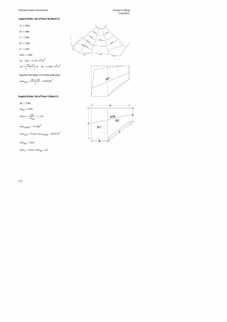
7/17/2019 Structural Design Project of Super Tall Building Chicago Spire
http://slidepdf.com/reader/full/structural-design-project-of-super-tall-building-chicago-spire 204/474
14 $V14 1-4+-2 22 3-00 2-300 32-000 ,.2 0.1 1.32 .+ +., +., .+ .+ 3.3 .2 . .2 2. 3. 33., 2.+ +.0 ,.,
1+ $V1+ 1-4+-2 23, 3-00 2-,00 33-000 ,.31 0.1 1., .+ +., +., .+ .+ 3. . .4 . 2., 3.4 33.+ 3.0 +.2 ,.+
20 $V20 1-4+-2 20 3-00 3-100 3-000 ,.20 0.1 1.2 .1 +.+ +.+ .1 .1 .0 .0 .2 .0 2.+ 3.1 3.2 3.3 +. 4.1
21 $V21 1-4+-2 23 3-00 3-00 3-000 ,.0+ 0.1 1.,4 .2 0.0 0.0 .2 .2 .3 .3 . .3 2,.0 3.3 3. 3.3 +., 4.3
22 $V22 1-4+-2 2,, 3-400 3-00 3-000 .+4 0.1 1.+ . 0.2 0.2 . . . . ., . 2,.1 3. 3. 3. +.+ 4.
23 $V23 1-4+-2 2+0 -000 3-+00 3,2-000 .44 0.1, 2.11 . 0. 0. . . ., .4 ,.0 .4 2,.3 3., 3., 3., 0.1 4.,
2 $V2 1-4+-2 303 -200 -300 341-000 .,, 0.1, 2.24 .4 0. 0. .4 .4 .1 ,.2 ,.3 ,.2 2,. 3,.0 3.0 3.+ 0. +.0
2.2.2 Wind Tunnel DataC-19
1 3 , + 11 13 1 1, 1+ 20 21 23 22 $V2 1-4+-2 31 -00 -,00 3+2-000 . 0.14 2. .0 0.4 0.4 .0 .0 . ,. ,., ,. 2,., 3,.3 3.3 .2 0., +.3
2 $V2 1-4+-2 32+ -00 -000 3++-000 . 0.14 2. .1 0.4 0.4 .1 .1 .4 ,.+ 4.0 ,.+ 2,.4 3,. 3. .2 0.+ +.
2, $V2, 1-4+-2 32 -00 -00 11-000 . 0.1+ 2.43 .3 1.0 1.0 .3 .3 .1 4.3 4.3 4.3 24.0 3,.4 3.4 . 1.2 +.,
24 $V24 1-4+-2 3 -400 -,00 14-000 .3 0.1+ 3.02 . 1.2 1.2 . . . 4. 4. 4. 24.1 34.0 3.0 . 1. +.+
2+ $V2+ 1-4+-2 3+ -000 -100 2,-000 .2 0.20 3.22 ., 1. 1. ., ., .4 +.0 +.0 +.0 24.3 34.3 3.2 .+ 1., 0.2
30 $V30 1-4+-2 342 -200 -00 33-000 .1 0.20 3.2 .+ 1. 1. .+ .+ ,.1 +.3 +.3 +.3 24. 34. 3. .1 2.0 0.
31 $V31 1-4+-2 3+ -00 -400 3-000 .0 0.20 3.2 ,.2 1.4 1.4 ,.2 ,.2 ,. +., +., +., 24., 34.4 3., .3 2.3 0.4
32 $V32 1-4+-2 04 -00 ,-100 1-000 .+ 0.21 3.43 ,. 2.0 2.0 ,. ,. ,.4 0.0 0.0 0.0 24.+ 3+.1 3.+ . 2. 1.0
33 $V33 1-4+-2 21 -400 ,-,00 4-000 .4 0.21 .0 ,. 2.2 2.2 ,. ,. 4.3 0. 0. 0. 2+.1 3+. 3,. .4 3.0 1.
3 $V3 1-4+-2 3 -000 4-000 ,-000 ., 0.21 .2 ,.4 2. 2. ,.4 ,.4 4. 0.+ 0.4 0.+ 2+.3 3+., 3,. .0 3.2 1.
3 $V3 1-4+-2 4 -300 4-300 ,-000 . 0.22 ., 4.1 2., 2., 4.1 4.1 4.+ 1.2 1.1 1.2 2+. 0.0 3,.4 .2 3. 1.+
3 $V3 1-4+-2 1 -00 4-,00 4-000 . 0.22 .4 4. 3.0 3.0 4. 4. +.3 1. 1. 1. 2+., 0.3 34.1 . 3.+ 2.3
3, $V3, 1-4+-2 , -400 +-000 +1-000 . 0.22 .+1 4., 3.2 3.2 4., 4., +. 1.+ 1.4 1.+ 2+.4 0. 34.3 ., .1 2.
34 $V34 1-4+-2 4, -400 +-000 ,+-000 .3 0.22 .13 4., 3.2 3.2 4., 4., +. 1.+ 1.4 1.+ 2+.4 0. 34.3 ., .1 2.
3+ $V3+ 1-4+-2 00 -400 +-000 ,0-000 .2 0.22 .3 4., 3.2 3.2 4., 4., +. 1.+ 1.4 1.+ 2+.4 0. 34.3 ., .1 2.0 $V0 1-4+-2 1 -400 +-000 ,0-000 .1 0.23 .4 4., 3.2 3.2 4., 4., +. 1.+ 1.4 1.+ 2+.4 0. 34.3 ., .1 2.
1 $V1 1-3+3-,11 2, -400 4-00 3,-000 .0, 0.31 .4+ ,., 2.3 2.3 ,., ,., +.1 1. 1.3 1. 2+. 0.1 3,.+ .0 3. 1.4
2 $V2 1-3+3-,11 0 -100 +-100 2-000 .+4 0.31 .20 4.0 2. 2. 4.0 4.0 +. 1.+ 1.4 1.+ 2+.4 0. 34.3 .3 3.4 2.2
3 $V3 1-3+3-,11 3 -200 +-300 ,-000 .44 0.31 .2 4.1 2., 2., 4.1 4.1 +.4 2.1 2.0 2.1 2+.+ 0. 34. . .0 2.3
$V 1-3+3-,11 -00 +-,00 3-000 .,+ 0.32 .4 4. 3.0 3.0 4. 4. 0.2 2. 2.3 2. 30.1 0.+ 34., ., .3 2.,
$V 1-3+3-,11 ,+ -00 +-+00 ,-000 .,0 0.32 ,.1 4. 3.1 3.1 4. 4. 0. 2., 2. 2., 30.2 1.1 34.4 .4 . 2.4
$V 1-3+3-,11 +3 -+00 0-00 -000 .1 0.32 ,., 4.+ 3. 3. 4.+ 4.+ 0.+ 3.3 3.1 3.3 30. 1. 3+.3 ,.2 .0 3.3
, $V, 1-3+3-,11 0 ,-200 0-400 ,-000 .2 0.32 ,.,+ +.2 3., 3., +.2 +.2 1.2 3. 3. 3. 30., 1.4 3+. ,. .3 3.
4 $V4 1-3+3-,11 1+ ,-00 1-300 ,3-000 .3 0.32 4.11 +. .0 .0 +. +. 1., .1 3.+ .1 30.+ 2.2 3+.4 ,., ., 3.+
+ $V+ 1-3+3-,11 32 ,-400 1-400 ,,-000 .3 0.32 4.3 +.+ .3 .3 +.+ +.+ 2.2 . . . 31.2 2. 0.2 4.0 .1 .3
0 $V0 1-3+3-,11 4-000 2-200 40-000 .2 0.32 4., 0.1 . . 0.1 0.1 2. .0 ., .0 31. 2.4 0. 4.3 . .
1 $V1 1-3+3-,11 4 4-300 2-00 4-000 .1, 0.32 +.0, 0. .4 .4 0. 0. 2.+ . .1 . 31. 3.2 0.4 4. .4 .0
2 $V2 1-3+3-,11 ,2 4-00 3-100 4,-000 .0+ 0.32 +.3+ 0., .1 .1 0., 0., 3. .+ . .+ 31.4 3. 1.1 4.+ ,.2 .
3 $V3 1-3+3-,11 4 4-400 3-00 +0-000 .00 0.32 +.,1 1.0 .3 .3 1.0 1.0 3.+ . .1 . 32.1 3.+ 1. +.1 ,. .,
$V 1-3+3-,11 +4 +-000 -000 +2-000 3.+2 0.32 10.03 1.2 . . 1.2 1.2 .3 .4 . .4 32.3 .2 1., +.3 ,.4 .0 $V 1-3+3-,11 ,11 +-00 -00 +4-000 3.4 0.32 10.3 1. .+ .+ 1. 1. .4 ,.3 ,.0 ,.3 32. . 2.1 +., 4.3 .
$V 1-3+3-,11 ,2 +-400 -+00 02-000 3., 0.32 10., 2.0 .3 .3 2.0 2.0 .2 ,.4 ,. ,.4 32.4 .+ 2. 0.1 4., .4
, $V, 1-3+3-,11 ,3, 0-000 -00 03-000 3., 0.32 10.++ 2.3 . . 2.3 2.3 ., 4.3 ,.+ 4.3 33.1 . 2.4 0.3 +.1 ,.2
4 $V4 1-3+3-,11 ,1 0-300 -+00 0-000 3.+ 0.32 11.30 2. .4 .4 2. 2. .1 4.4 4.3 4.4 33.3 ., 3.1 0. +. ,.
+ $V+ 1-3+3-,11 , 0-,00 -300 0+-000 3.1 0.31 11.2 3.0 ,.2 ,.2 3.0 3.0 . +.2 4., +.2 33. .0 3. 1.0 +.+ 4.0
0 $V0 1 3+3 ,11 ,,, 1 000 +00 1 000 3 3 0 31 11 +3 3 3 , , 3 3 3 3 , 1 + 4 + 3 + 4 33 4 3 4 1 3 0 4
Criti!al #or!e
;(ips=
# Resultant * ;#72 < #y
2= ;(ips=
for ea!> load !ase#or!e #y ;lb= orsion "A
;lbft=
Criti!al
"oment ;(ip
ft )<=
InterBtory
Drift ;in=
otal Drift
;in=#loor $e'el
"oment of
Inertia ;ft=
?ei@>t %bo'e
$e'el $V1 ;ft= #or!e #7 ;lb=

7/17/2019 Structural Design Project of Super Tall Building Chicago Spire
http://slidepdf.com/reader/full/structural-design-project-of-super-tall-building-chicago-spire 205/474
0 $V0 1-3+3-,11 ,,, 1-000 -+00 1-000 3.3 0.31 11.+3 3.3 ,. ,. 3.3 3.3 ,.1 +.4 +.3 +.4 33.4 . 3.4 1.3 0. 4.
1 $V1 1-3+3-,11 ,+0 1-100 ,-200 13-000 3.3 0.31 12.2 3. ,. ,. 3. 3. ,.3 0.1 +. 0.1 3.0 ., .0 1. 0. 4.
2 $V2 1-3+3-,11 403 1-00 ,-400 1-000 3.24 0.31 12. 3.+ 4.0 4.0 3.+ 3.+ ,.+ 0., 0.2 0., 3.3 ,.1 . 1.+ 1.1 +.1
3 $V3 1-3+3-,11 41 1-,00 4-100 14-000 3.20 0.31 12.4 .1 4.2 4.2 .1 .1 4.2 1.0 0. 1.0 3. ,.3 ., 2.1 1. +.3
$V 1-3+3-,11 430 2-,00 +-00 3+-000 3.13 0.30 13.1 .2 +.2 +.2 .2 .2 +. 2.3 1.4 2.3 3.2 4. . 3.0 2. 0.
$V 1-3+3-,11 43 3-000 +-400 -000 3.0 0.30 13. . +. +. . . +.+ 2., 2.1 2., 3. 4., .+ 3.3 2.+ 0.4
$V 1-3+3-,11 4 3-00 0-00 -000 2.+4 0.30 13., .+ +.+ +.+ .+ .+ 0. 3.3 2., 3.3 3., +.1 . 3., 3. 1.3
2.2.2 Wind Tunnel Data C-20
1 3 , + 11 13 1 1, 1+ 20 21 23 2, $V, 1-3+3-,11 4+ 3-000 0-100 2+-000 2.+1 0.30 1.0 . +. +. . . 0.1 3.0 2. 3.0 3. 4.+ .1 3. 3.1 0.+
4 $V4 1-3+3-,11 442 3-00 0-,00 3-000 2.43 0.2+ 1.3 .1 0.0 0.0 .1 .1 0., 3. 3.0 3. 3.4 +. . 3.4 3. 1.
+ $V+ 1-3+3-,11 4+ 3-400 1-200 3-000 2., 0.2+ 1. . 0.3 0.3 . . 1.2 .1 3. .1 3.1 +., .+ .1 .0 1.+
,0 $V,0 1-3+3-,11 +0+ -100 1-00 34-000 2.+ 0.2+ 1.+3 ., 0. 0. ., ., 1. . 3.+ . 3.3 0.0 ,.2 . . 2.2
,1 $V,1 1-3+3-,11 +22 -200 1-+00 34-000 2.2 0.24 1.22 .4 0., 0., .4 .4 1.+ .4 .2 .4 3. 0.3 ,. . . 2.
,2 $V,2 1-3+3-,11 +3 -200 2-000 20-000 2. 0.24 1.0 .4 0., 0., .4 .4 2.0 .+ .3 .+ 3. 0.3 ,. . ., 2.
,3 $V,3 1-3+3-,11 +4 -200 2-000 20-000 2.+ 0.24 1.,, .4 0., 0., .4 .4 2.0 .+ .3 .+ 3. 0.3 ,. . ., 2.
, $V, 1-3+3-,11 +1 -200 2-000 20-000 2.2 0.2, 1.0 .4 0., 0., .4 .4 2.0 .+ .3 .+ 3. 0.3 ,. . ., 2.
, $V, 41-004 +, 0-+00 4-00 3++-000 2.3 0. 1.1 3. ,. ,. 3. 3. 4. 1. 0.4 1. 3. ,. .+ 1., 1.2 +.2
, $V, 41-004 +44 1-100 4-+00 02-000 2.2+ 0. 1.+ 3. ,.4 ,.4 3. 3. 4.+ 1., 1.1 1., 3., ,.4 .1 1.+ 1. +.
,, $V,, 41-004 1-001 1-200 +-200 00-000 2.23 0. 1,.1 3., ,.+ ,.+ 3., 3., +.2 2.0 1.3 2.0 3.4 4.0 .3 2.1 1., +.
,4 $V,4 41-004 1-01 1-00 +-00 03-000 2.1 0. 1,.4 .0 4.2 4.2 .0 .0 +. 2. 1., 2. 3.0 4. . 2. 2.1 +.+
,+ $V,+ 41-004 1-02, 2-000 0-200 0-000 2.10 0.3 14.2+ . 4. 4. . . 0.1 3.0 2.3 3.0 3. 4.4 .1 2.4 2. 0.
40 $V40 41-004 1-00 2-000 0-200 00-000 1.++ 0., 1+.03 . 4. 4. . . 0.1 3.0 2.3 3.0 3. 4.4 .1 2.4 2. 0.
41 $V41 41-004 1-03 2-100 0-00 3++-000 1.+4 0.10 1+.13 ., 4.4 4.4 ., ., 0.3 3.2 2. 3.2 3. +.0 .2 2.+ 2.4 0.42 $V42 41-004 1-0, 2-00 0-+00 3++-000 1.+2 0.1 1+. .1 +.1 +.1 .1 .1 0.4 3., 3.0 3., 3.4 +. . 3.3 3.2 1.1
43 $V43 41-004 1-040 2-400 1-200 3++-000 1.4 0.0 1+.+ . +. +. . . 1.1 .0 3.3 .0 3.+ +. .4 3. 3. 1.
4 $V4 41-004 1-0+3 3-200 1-,00 02-000 1.40 0.0 20.3 .+ +.4 +.4 .+ .+ 1. . 3.4 . 3.2 0.0 ,.2 3.+ .0 1.4
4 $V4 41-004 1-10 3-300 1-400 3+4-000 1., 0.3+ 20., .0 +.+ +.+ .0 .0 1., ., 3.+ ., 3.3 0.1 ,.2 .0 .1 1.+
4 $V4 41-004 1-11+ 3-400 2-00 01-000 1.+ 0.34 21.12 . 0. 0. . . 2.3 .3 . .3 3. 0. ,., . ., 2.
4, $V4, 41-004 1-132 -200 2-+00 03-000 1.3 0.3, 21.+ .+ 0.4 0.4 .+ .+ 2.4 .4 .0 .4 3.+ 1.0 4.1 .+ .2 2.+
44 $V44 41-004 1-1 -00 3-200 00-000 1.4 0.3 21.4 ,.1 1.0 1.0 ,.1 ,.1 3.1 .1 .3 .1 3,.0 1.2 4.3 .1 . 3.2
4+ $V4+ 41-004 1-1+ -400 3-00 01-000 1.2 0.3 22.21 ,. 1. 1. ,. ,. 3. . ., . 3,.3 1. 4. . .4 3.
+0 $V+0 41-004 1-1,2 -400 3-00 3+-000 1., 0.3 22. ,. 1. 1. ,. ,. 3. . ., . 3,.3 1. 4. . .4 3.
+1 $V+1 41-004 1-14 -00 -200 3+4-000 1.2 0.3 22.+0 4.2 1.+ 1.+ 4.2 4.2 .1 ,.1 . ,.1 3,. 2.0 +.0 .+ . .2
+2 $V+2 41-004 1-1+4 -400 -,00 01-000 1.3 0.33 23.23 4. 2.3 2.3 4. 4. . ,. .+ ,. 3,.+ 2. +. .3 .+ .
+3 $V+3 41-004 1-211 -100 -100 3++-000 1.31 0.32 23. 4.+ 2. 2. 4.+ 4.+ .+ 4.1 ,.3 4.1 34.1 2., +., . ,.3 .+
+ $V+ 41-004 1-22 -200 -300 3+-000 1.2, 0.31 23.4, +.0 2., 2., +.0 +.0 .1 4.3 ,. 4.3 34.2 2.4 +.4 ., ,. .1
+ $V+ 41-004 1-234 -00 -00 34+-000 1.22 0.31 2.1, +.3 2.+ 2.+ +.3 +.3 . 4. ,., 4. 34. 3.1 0.1 .+ ,., .3
+ $V+ 41-004 1-21 -,00 -000 344-000 1.1, 0.30 2., +. 3.2 3.2 +. +. .4 +.0 4.1 +.0 34. 3. 0.3 ,.2 4.0 .,+, $V+, 41-004 1-2 ,-000 -00 34-000 1.12 0.2+ 2., +.+ 3. 3. +.+ +.+ .2 +. 4. +. 34.4 3., 0. ,. 4. .0
+4 $V+4 41-004 1-2,, ,-00 -+00 34,-000 1.04 0.24 2.03 ,0. .0 .0 ,0. ,0. ., +.+ +.1 +.+ 3+.1 .1 1.0 ,.+ 4.+ .
++ $V++ 41-004 1-2+0 ,-,00 ,-300 34-000 1.03 0.2, 2.30 ,0. .2 .2 ,0. ,0. ,.1 ,0.3 +. ,0.3 3+.3 . 1.3 4.1 +.2 .4
100 $V100 41-004 1-30 4-200 ,-00 34-000 0.++ 0.2 2., ,1.2 . . ,1.2 ,1.2 ,. ,0. +.4 ,0. 3+. ., 1. 4. +. ,.2
101 $V101 41-004 1-31, 4-400 4-000 34-000 0.+ 0.2 2.42 ,1.4 .2 .2 ,1.4 ,1.4 ,.4 ,1.1 ,0.2 ,1.1 3+.4 .0 1.+ +.0 ,0.1 ,.,
102 $V102 41-004 1-330 +-000 4-100 342-000 0.+0 0.2 2.0 ,2.0 . . ,2.0 ,2.0 ,.+ ,1.2 ,0.3 ,1.2 3+.4 .1 2.0 +.1 ,0.3 ,.+
#loor $e'el"oment of
Inertia ;ft=
?ei@>t %bo'e
$e'el $V1 ;ft= #or!e #7 ;lb= #or!e #y ;lb=
orsion "A
;lbft=
Criti!al
"oment ;(ip
ft )<=
InterBtory
Drift ;in=
otal Drift
;in=
Criti!al #or!e
;(ips=
# Resultant * ;#72 < #y
2= ;(ips=
for ea!> load !ase

7/17/2019 Structural Design Project of Super Tall Building Chicago Spire
http://slidepdf.com/reader/full/structural-design-project-of-super-tall-building-chicago-spire 206/474
102 $V102 41-004 1-330 +-000 4-100 342-000 0.+0 0.2 2.0 ,2.0 . . ,2.0 ,2.0 ,.+ ,1.2 ,0.3 ,1.2 3+.4 .1 2.0 +.1 ,0.3 ,.+
103 $V103 41-004 1-33 +-400 4-00 34-000 0.4 0.2 2.30 ,2.4 .1 .1 ,2.4 ,2.4 4. ,1. ,0.4 ,1. 0.1 . 2.3 +., ,0.+ 4.
10 $V10 41-004 1-3 ,0-200 4-00 343-000 0.42 0.23 2.3 ,3.2 . . ,3.2 ,3.2 4. ,1.4 ,1.0 ,1.4 0.2 . 2. +.+ ,1.1 4.,
10 $V10 41-004 1-3+ ,0-,00 4-400 342-000 0.,4 0.22 2., ,3., .+ .+ ,3., ,3., 4., ,2.0 ,1.2 ,2.0 0. .4 2. 0.3 ,1. +.1
10 $V10 41-004 1-343 ,1-200 +-000 343-000 0., 0.21 2.+ ,.1 ,.3 ,.3 ,.1 ,.1 4.+ ,2.2 ,1. ,2.2 0. .0 2.4 0. ,1.4 +.
10, $V10, 41-004 1-3+ ,1-00 +-300 342-000 0.,1 0.20 2,.1 ,. ,., ,., ,. ,. +.3 ,2. ,1.4 ,2. 0.4 .2 3.1 0.+ ,2.2 +.4
104 $V104 41-004 1-0+ ,1-+00 +-00 340-000 0., 0.1+ 2,.3 ,.+ 4.0 4.0 ,.+ ,.+ +. ,2., ,1.+ ,2., 0.+ .3 3.2 1.1 ,2. ,0.0
2.2.2 Wind Tunnel DataC-21
1 3 , + 11 13 1 1, 1+ 20 21 23 210+ $V10+ 41-004 1-22 ,0-000 +-000 341-000 0. 0.14 2,.3 ,3.0 .3 .3 ,3.0 ,3.0 4.4 ,2.1 ,1.3 ,2.1 0. .4 2., +.+ ,1.3 4.4
110 $V110 41-004 1-3 ,0-000 +-000 341-000 0.0 0.14 2,.,1 ,3.0 .3 .3 ,3.0 ,3.0 4.4 ,2.1 ,1.3 ,2.1 0. .4 2., +.+ ,1.3 4.4
111 $V111 41-004 1-4 ,0-000 +-000 341-000 0., 0.1, 2,.44 ,3.0 .3 .3 ,3.0 ,3.0 4.4 ,2.1 ,1.3 ,2.1 0. .4 2., +.+ ,1.3 4.4
112 $V112 41-004 1-2 +-300 -+00 33,-000 0. 0.1 24.0 ,2.1 . . ,2.1 ,2.1 .+ ,0.1 +.3 ,0.1 3+. .3 1.2 4.+ +.4 ,.
113 $V113 24-43 1-, +-00 ,-200 333-000 0.1 0.0 24. ,2. ., ., ,2. ,2. ,.2 ,0. +. ,0. 3+. . 1. +.1 ,0.0 ,.,
11 $V11 24-43 1-44 +-400 ,-00 330-000 0., 0., 2+.02 ,2., .0 .0 ,2., ,2., ,. ,0.4 ,0.0 ,0.4 3+.4 .+ 1., +. ,0. 4.0
11 $V11 24-43 1-01 +-100 ,-000 322-000 0. 0. 2+., ,2.0 . . ,2.0 ,2.0 .+ ,0.1 +. ,0.1 3+. . 1.3 4.4 +., ,.
11 $V11 24-43 1-1 +-200 ,-000 31,-000 0.2 0.3 2+.4+ ,2.1 . . ,2.1 ,2.1 .+ ,0.1 +. ,0.1 3+. . 1.3 4.+ +.4 ,.
11, $V11, 24-43 1-2, ,0-000 ,-400 31-000 0.3+ 0.0 30.2+ ,2.+ .2 .2 ,2.+ ,2.+ ,., ,1.0 ,0.2 ,1.0 3+.+ .0 1.+ +. ,0. 4.2
114 $V114 24-43 1-1 ,0-00 4-300 312-000 0.3 0.34 30., ,3. ., ., ,3. ,3. 4.2 ,1. ,0., ,1. 0.2 . 2.3 0.0 ,1.1 4.,
11+ $V11+ 24-43 1- ,1-000 4-,00 310-000 0.3 0.3 31.02 ,3.+ ,.1 ,.1 ,3.+ ,3.+ 4., ,1.+ ,1.2 ,1.+ 0. .4 2. 0. ,1. +.2
120 $V120 24-43 1-, ,1-100 4-400 30,-000 0.31 0.33 31.3 ,.0 ,.2 ,.2 ,.0 ,.0 4.4 ,2.0 ,1.3 ,2.0 0. .4 2., 0. ,1., +.3
121 $V121 24-43 1-40 ,1-00 +-300 30-000 0.2+ 0.31 31. ,. ,., ,., ,. ,. +.3 ,2. ,1.4 ,2. 0.4 .2 3.1 0.+ ,2.2 +.4
122 $V122 24-43 1-+3 ,,-,00 ,-00 31-000 0.2, 0.2+ 31.+ 40.+ ,3. ,3. 40.+ 40.+ ,. ,+.0 ,4.2 ,+.0 . 1.2 ,.4 .2 ,4. ,.4
123 $V123 24-43 1-0 ,0-100 ,-,00 20-000 0.2 0.2, 32.22 ,3.0 .3 .3 ,3.0 ,3.0 ,., ,0.+ ,0.2 ,0.+ 3+.+ .0 1.4 +. ,0. 4.212 $V12 24-43 1-20 -,00 3-100 2-000 0.22 0.2 32., 4. 2.1 2.1 4. 4. 3.1 .1 . .1 3,.2 1.3 4. .4 .0 3.4
12 $V12 24-43 1-33 -00 3-+00 2-000 0.20 0.23 32.+ +.2 2.4 2.4 +.2 +.2 3.+ .+ .3 .+ 3,., 1.+ +.0 . .4 .
12 $V12 24-43 1- -00 3-+00 24-000 0.1+ 0.21 32.+0 +.2 2.4 2.4 +.2 +.2 3.+ .+ .3 .+ 3,., 1.+ +.0 . .4 .
12, $V12, 24-43 1-+ -100 3-00 21-000 0.1, 0.1+ 33.0+ 4.4 2. 2. 4.4 4.4 3. . .+ . 3,. 1. 4., .1 . .2
124 $V124 24-43 1-,2 -00 3-+00 24-000 0.1 0.1, 33.2 +.2 2.4 2.4 +.2 +.2 3.+ .+ .3 .+ 3,., 1.+ +.0 . .4 .
12+ $V12+ 24-43 1-4 ,-000 -000 22-000 0.13 0.1 33.2 +., 3.3 3.3 +., +., .0 ,.1 . ,.1 3,.4 2.0 +.1 .4 ,.1 .+
130 $V130 24-43 1-++ ,-+00 -00 23,-000 0.12 0.1 33. ,0. .1 .1 ,0. ,0. . ,. .+ ,. 34.1 2. +. ,. ,.4 .
131 $V131 24-43 1-,12 4-00 -400 233-000 0.10 0.12 33.4 ,1.2 . . ,1.2 ,1.2 .+ 4.0 ,. 4.0 34. 2.4 +.4 ,.+ 4.3 .0
132 $V132 24-43 1-,2 4-00 -00 22-000 0.0+ 0.11 33.,+ ,1.2 . . ,1.2 ,1.2 ., ,.4 ,.2 ,.4 34.3 2. +., ,.4 4.2 .+
133 $V133 24-43 1-,34 4-200 -300 21,-000 0.04 0.10 33.4+ ,0.+ .3 .3 ,0.+ ,0.+ . ,. .+ ,. 34.1 2. +. ,. ,.+ .
13 $V13 24-43 1-,1 4-100 -100 211-000 0.0, 0.04 33.+, ,0.4 .2 .2 ,0.4 ,0.4 .2 ,.3 ., ,.3 34.0 2.2 +.3 ,. ,., .
13 $V13 24-43 1-, ,-00 3-00 202-000 0.0 0.0, 3.0 ,0.2 3.4 3.4 ,0.2 ,0.2 3. ., .1 ., 3,., 1.4 4.+ ,.0 ,.1 .+
13 $V13 24-43 1-,,4 ,-000 2-+00 1+3-000 0.0 0.0 3.11 +. 3.2 3.2 +. +. 3.0 .0 . .0 3,.3 1.3 4. . . .3
13, $V13, 24-43 1-,+1 -00 2-00 14-000 0.0 0.0 3.1 +.2 2.4 2.4 +.2 +.2 2. . .0 . 3,.0 0.+ 4.0 .1 .1 3.+
134 $V134 24-43 1-40 -400 1-00 1,-000 0.03 0.0 3.20 4.3 2.0 2.0 4.3 4.3 1.4 ., .2 ., 3. 0.2 ,. . .2 3.113+ $V13+ 24-43 1-41, -00 0-00 1-000 0.02 0.03 3.23 ,.1 0.+ 0.+ ,.1 ,.1 0. 3. 2.+ 3. 3.+ +.3 . . .0 1.+
10 $V10 24-43 1-430 2-100 4-000 14-000 0.02 0.02 3.2 . 4. 4. . . 4.2 0.+ 0. 0.+ 3. ,.3 ., 2.3 1. +.
11 $V11 24-43 1-43 +-00 -00 12+-000 0.01 0.02 3.2, 1., .0 .0 1., 1., . 4.2 ,., 4.2 32.+ .2 2., 0.0 4.4 .+
12 $V12 24-43 1-4, ,-400 ,1-00 11-000 0.01 0.01 3.24 ,4.4 ,1. ,1. ,4.4 ,4.4 ,1. ,.+ ,.3 ,.+ 2.3 4.2 .+ .0 ,. ,2.+
13 $V13 24-43 1-4,0 ,1-000 -00 10-000 0.00 0.01 3.2+ ,3.4 ,.0 ,.0 ,3.4 ,3.4 .4 +.+ +. +.+ 3+. .3 1.3 +.4 ,0. 4.1
1 $V1 24-43 1-443 -00 0-,00 +2-000 0.00 0.00 3.2+ . 1. 1. . . 0.+ 3.3 2.+ 3.3 30.2 1. 3+.1 .4 3.+ 2.1
# Resultant * ;#72 < #y
2= ;(ips=
for ea!> load !aseorsion "A
;lbft=
Criti!al
"oment ;(ip
ft )<=
InterBtory
Drift ;in=
otal Drift
;in=
Criti!al #or!e
;(ips=#loor $e'el
"oment of
Inertia ;ft=
?ei@>t %bo'e
$e'el $V1 ;ft= #or!e #7 ;lb= #or!e #y ;lb=

7/17/2019 Structural Design Project of Super Tall Building Chicago Spire
http://slidepdf.com/reader/full/structural-design-project-of-super-tall-building-chicago-spire 207/474
1 $V1 24-43 1-4+ 4-00 -,00 +2-000 0.00 0.00 3.30 0.4 .1 .1 0.4 0.4 .4 ,. ,.0 ,. 32. . 2.1 +.2 4.0 .1
1 $V1 24-43 1-+0+ 4-00 -,00 +2-000 0.00 0.00 3.30 0.4 .1 .1 0.4 0.4 .4 ,. ,.0 ,. 32. . 2.1 +.2 4.0 .1
otal 4-++-000 4-2,-200 2-4-000
2.2.2 Wind Tunnel Data C-22
2.3 Seismic Calculations
2.3.1 Seismic Weight Calculation 24
2.3.2 Seismic Load Calculation 29
3,000
4,000
5,000
6,000
7,000
t o r y S h e a r ( k
i p s )
Story Shear# $%
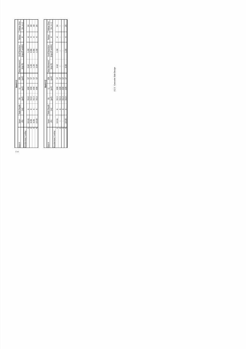
7/17/2019 Structural Design Project of Super Tall Building Chicago Spire
http://slidepdf.com/reader/full/structural-design-project-of-super-tall-building-chicago-spire 208/474
0
1,000
2,000
0 20 40 60 80 100 120 140 160
S t
loor !um"er
100.00
150.00
200.00
250.00
o r c e
( k i p s ) a c t i n g o n e a c h & l o o r
Seismic orce 's. loor !um"er

7/17/2019 Structural Design Project of Super Tall Building Chicago Spire
http://slidepdf.com/reader/full/structural-design-project-of-super-tall-building-chicago-spire 209/474
e i g h
t C a l c u l a o n
c w e i g
h t o
f t h e
b u i l d i n g u s i n g p r e
l i m i n a r y c o r e s i z e s .
e s f c
1 4
k s i
: =
E c o n c
5 0 0 0
f c p s i
⋅
⋅
! .
1 " 1
0 #
×
p s f
=
: =
u t e r
D i m e n s i o n s :
0 %
4
%
4
%
"
"
5
f t
: = h
e b a
n k n u m
b e r
r b (
) " r b (
) 4
2 . 3 . 1
S e i s m i c W e i g h t C a l c u l a t i o n
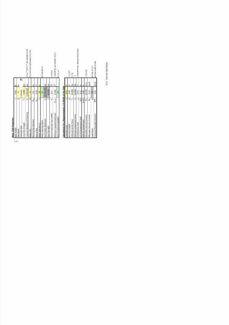
7/17/2019 Structural Design Project of Super Tall Building Chicago Spire
http://slidepdf.com/reader/full/structural-design-project-of-super-tall-building-chicago-spire 210/474
&
-
% ! p s f
: =
/ & -
1 0 p s f
: =
&
&
% " p s f
: =
/ & &
5 p s f
: =
&
$
% "
. 5 p s f
: =
/ & $
% 4 p s f
:
=
s : . % # !
1 0
4
×
f t "
r " o o r :
& * l o b b y
+ a n
d
$ * r e s i d e n a
l + a
r e t h e w e i g
h t s o
f i n
d i 2 i d u a
l
c o
l u m
n
c l a d d i n g
o r c o r e w e i g
h t s .
-
/ & -
+
)
) f l o o r
⋅
4 . 0
1 5
1 0
%
×
k i p
=
) f l o o r
⋅
1 . "
% 6
1 0
%
×
k i p
=
& $
+
/ & $
+
)
) f l o o r
⋅
1 . 0 6 %
1 0
%
×
k i p
=
2 . 3 . 1
S e i s m i c W e i g h t C a l c u l a t i o n

7/17/2019 Structural Design Project of Super Tall Building Chicago Spire
http://slidepdf.com/reader/full/structural-design-project-of-super-tall-building-chicago-spire 211/474
% %
=
n $ %
% 4
: =
% 1
=
n $ 4
% %
: =
n $
%
+
n $ 4
+
1 % 1
=
n -
+
1 4
=
t s p e
r " o o r # $ # a n % :
) 1 *
+
4 . 5
# #
1 0
%
×
k i p
=
) " *
+
% . 4
5
1 0
%
×
k i p
=
) % *
+
" . "
# 4
1 0
%
×
k i p
=
) 4 *
+
1 . 0
5 %
1 0
%
×
k i p
=
p e r " o o r # $ # a n % & s e e ! a # l e ' i n ( r a ) i t $ S $ s t e m
* e p o r t + :
" 1⋅
4 " i n 4 " ⋅
i n
*
+ ⋅
% 6 i n % 6
⋅
i n
*
+ 1 4 ⋅
+
7 h f l o o r
⋅
ρ c ⋅
+
5 %
" . "
1 %
k i p
=
" 1⋅
% 0 i n % 0 ⋅
i n
*
+ ⋅
" 4 i n " 4
⋅
i n
*
+ 1 4 ⋅
+
7 h f l o o r
⋅
ρ c ⋅
+
% "
# . 0
1 "
k i p
=
1 4
% 0 i n % 0 ⋅
i n h f l o o r
⋅
ρ c ⋅
(
)
1 4 ⋅
+
1 ! !
. 4 ! !
k i p
=
1 4
1 # i n 1 # ⋅
i n h f l o o r
⋅
ρ c ⋅
(
)
1 4 ⋅
+
# 4
. 6 %
k i p
=
2 . 3 . 1
S e i s m i c W e i g h t C a l c u l a t i o n
5 .
6 5
1 0
4
×
k i p
=4
)
% . #
4 1 1
0 4
×
k i p
= %
+
)
n $ 4
4
4
+
(
)
⋅
+
5 . 5
5 % 1
0 5
×
k i p
=

7/17/2019 Structural Design Project of Super Tall Building Chicago Spire
http://slidepdf.com/reader/full/structural-design-project-of-super-tall-building-chicago-spire 212/474
s p e r
" o o r :
o o r d ⋅
π ⋅
5 5
. 0 " #
k i p
=
" o o
r t $ p e :
-
l a d
+
)
"
1
"
+
%
+
4
+
1
+
" +
%
+
4
+
(
)
⋅
+
&
l a d
⋅
5
1
1
+
(
)
⋅
+
1
"
%
+
4
+
"
+
%
+
4
+
(
⋅
+
l a d
+
)
n $ 1
1
1
+
(
)
⋅
+
n $ "
"
"
+
(
)
⋅
+
n $ %
% +
(
⋅
+
2 . 3 . 1
S e i s m i c W e i g h t C a l c u l a t i o n

7/17/2019 Structural Design Project of Super Tall Building Chicago Spire
http://slidepdf.com/reader/full/structural-design-project-of-super-tall-building-chicago-spire 213/474
- u i l d
i n g :
& 8 o t
$ 8 o t
+
6 . 5
1 %
1 0
5
×
k i p
=
n g o n
c o r e
.
d c l a
d d i n g
d o n o t
l o a
d c o r e
w e i g
h t i s c a r r i e
d b y c o r e
.
" )
1
(
)
⋅
1 "
n $ 1
$
⋅
"
-
⋅
+
5 &
⋅
+
(
)
⋅
+
" . 0
# 1
1 0
5
×
k i p
=
" )
"
(
)
⋅
1 " n $ "
$
⋅
"
-
⋅
+
1 &
⋅
+
(
)
+
1 . %
! %
1 0
5
×
k i p
=
" )
%
(
)
⋅
1 " n $ %
$
⋅
"
-
⋅
+
1 &
⋅
+
(
)
+
1 . 0
"
1 0
5
×
k i p
=
" )
4
(
)
⋅
1 " n $ 4
$
⋅
"
-
⋅
+
1 &
⋅
+
(
)
+
6 . 0
0 6
1 0
4
×
k i p
=
8 9 8 c o r e
1
"
+
%
+
4
+
5 . 1
4
1 0
5
×
k i p
=
: =
2 . 3 . 1
S e i s m i c W e i g h
t C a l c u l a t i o n
C r e a t e d b y :
C J B
4 / 2 7 / 2 0 1 2
y :
' % e r ( n $ u t
C o n % t a n t / ) r e * i o u % C a l + .
C a l + / o o # u $
e %
) a % % e % C h e + #
o
a
i l % C h e + #
W e + h a n i + a l
n o b b y
n e % i d e n t i a l
n 3 e + h a n i + a l T o t a l B a n k
W e
i g h t
# i $ % / - l o o r
# i $ % / b a n #
1 0
5
2
2 . 5 6 ! " 0 5
8 9 n - l o o r t y $ e
W - l o o r t y $ e
;
7 7
1
1
2
1 . 7 4 ! " 0 5
6 5 5
1
4
2
1 . ! " 0 5
5 2 0
1
2
. 7 2 ! " 0 4
T o t a l :
6 . 5 6 ! " 0 5
C a l + u l a t i o n %
+ a g o = $ i r e . T h e A
e i g h t % b y - l o o r t y $ e a r e
d a n d l i * e l o a d % - o
r e a + h t y $ i + a l - l o o r t y $ e .
y s t e # $ " e ! # s $
o o r
s # i ( L o ! & C ! l ( , l !
t i o % s

7/17/2019 Structural Design Project of Super Tall Building Chicago Spire
http://slidepdf.com/reader/full/structural-design-project-of-super-tall-building-chicago-spire 214/474
2 . 3 . 2 S e i s m i c L o a d C a l c u l a t i o n s
B a s e S h e a r C a l c u l a t i o n
s a n d E f f e c t i v e S e i s m i c W e i g h t
T o t a l B u i l d i n g W e i g h t , W
t o t
6 . 5 6 ! " 0 5 # i $ %
N O T E : S E I S M I C W E I G H T I S D I F F
E R E N T T H A N A C T U A L W E I G H T
C o l o r & e y
4 0 1
5
# i $ % / - l o o r
1 2
6
# i $ % / - l o o r
1 0 6
# i $ % / - l o o r
B a n #
C o r e W a l l
W e i g h t
C o l u n
W e i g
h t
C l a d d i n g
W e i g h t
W l o b b y
W r e % i d e n t i a l
# i $ % / - l o o r
# i $ % / - l o o r
# i $ % / - l o o r
# i $ % / - l o o r
# i $ % / - l o o r
1
4 5
5 2
5 5 . 0
6 4 1 1
6 2
2
4 7 5
2
5 5 . 0
5 0 4
4 2 1
2 2 4
1
5 5 . 0
7 7 4
6 0 1
4
1 0 5
5
5 5 . 0
2 4 2
2 2 5 6
C %
0 . 0 1
T o t a l < e % i g n B a % e = h e a r
6 5 6
# i $ %
! > a u a t i o n % - r o ? = C ! 7 @
1 0 C h a $ t e r % 1 1 a n d 1 2 u % e d i n = e i % i + o r + e C
= $ r e a d % h e e t + a l + u l a t e % t h e e - - e + t i * e A e i g h t a n d b a % e % h
e a r o - t h e C h i +
+ a l + u l a t e d u % i n g a 3 a t h +
a d - i l e + o b i n i n g t h e $ r e * i o u % l y d e - i n e d d e a d
W f l o o r t y p e i s w e i g t o f s l ! " s y
! % & ' e r t i ( ! l e l e # e % t s p e r f l o
3 e + h a n i + a l
o b b y
e % i d e n t i a l W
e i g h t % b y - l o o r t y $ e
) * + * ) S e i s
C-29
Seismic Load Calculations Created by: CJB 4/27/2012
Floor Level Floor Type Weight Height wxhxk
Cvx Lateral Force Story Shear Moment
x wx, kips hx, t t!kips Fx, kips "x, kips k!t
147 Mechanical 5.21E+03 1935.50 1.95E+10 0.03252 213.43 213 0
146 Mechanical 5.21E+03 1922.33 1.92E+10 0.0320 210.54 424 2!10
145 "e#idential 2.26E+03 1909.17 .22E+09 0.01371 9.96 514 !393
144 "e#idential 2.26E+03 196.00 .11E+09 0.01352 .72 603 15!159
143 "e#idential 2.26E+03 12.3 .00E+09 0.01333 7.49 690 23!094
142 "e#idential 2.26E+03 169.67 7.9E+09 0.01315 6.27 776 32!11
141 "e#idential 2.26E+03 156.50 7.7E+09 0.01296 5.06 61 42!404
140 "e#idential 2.26E+03 143.33 7.67E+09 0.0127 3.6 945 53!747139 "e#idential 2.26E+03 130.17 7.56E+09 0.01260 2.67 1!02 66!194
13 "e#idential 2.26E+03 117.00 7.45E+09 0.01242 1.4 1!109 79!729
137 "e#idential 2.26E+03 103.3 7.34E+09 0.01224 0.30 1!190 94!33
136 " id ti l 2 26E+03 1790 67 7 23E+09 0 01206 79 14 1 269 110 003
& ' 6563! ( ' 5.6! ) ' 2
Calc*lati%n ba#ed %n ,CE 7-10 Chater# 11 and 12 %r #ei#ic l%ad#.

7/17/2019 Structural Design Project of Super Tall Building Chicago Spire
http://slidepdf.com/reader/full/structural-design-project-of-super-tall-building-chicago-spire 215/474
136 "e#idential 2.26E+03 1790.67 7.23E+09 0.01206 79.14 1!269 110!003
135 "e#idential 2.26E+03 1777.50 7.13E+09 0.011 77.9 1!347 126!711
134 "e#idential 2.26E+03 1764.33 7.02E+09 0.01171 76.3 1!424 144!445
133 "e#idential 2.26E+03 1751.17 6.92E+09 0.01153 75.6 1!499 163!191132 "e#idential 2.26E+03 173.00 6.1E+09 0.01136 74.55 1!574 12!934
131 "e#idential 2.26E+03 1724.3 6.71E+09 0.01119 73.42 1!647 203!65
130 "e#idential 2.26E+03 1711.67 6.61E+09 0.01102 72.31 1!720 225!34
129 "e#idential 2.26E+03 169.50 6.51E+09 0.0105 71.20 1!791 247!991
12 "e#idential 2.26E+03 165.33 6.41E+09 0.0106 70.10 1!61 271!571
127 "e#idential 2.26E+03 1672.17 6.31E+09 0.01052 69.01 1!930 296!075
126 "e#idential 2.26E+03 1659.00 6.21E+09 0.01035 67.93 1!99 321!46
125 "e#idential 2.26E+03 1645.3 6.11E+09 0.01019 66.5 2!065 347!793
124 "e#idential 2.26E+03 1632.67 6.01E+09 0.01002 65.79 2!131 374!979
123 "e#idential 2.26E+03 1619.50 5.92E+09 0.0096 64.73 2!195 403!032
122 "e#idential 2.26E+03 1606.33 5.2E+09 0.00970 63.6 2!259 431!937
121 "e#idential 2.26E+03 1593.17 5.73E+09 0.00954 62.64 2!322 461!60
120 "e#idential 2.26E+03 150.00 5.63E+09 0.00939 61.61 2!33 492!24
119 "e#idential 2.26E+03 1566.3 5.54E+09 0.00923 60.59 2!444 523!62
11 "e#idential 2.26E+03 1553.67 5.45E+09 0.0090 59.5 2!503 555!05117 "e#idential 2.26E+03 1540.50 5.35E+09 0.0092 5.57 2!562 5!767
Floor Level Floor Type Weight Height wxhxk
Cvx Lateral Force Story Shear Moment
x wx, kips hx, t t!kips Fx, kips "x, kips k!t
& ' 6563! ( ' 5.6! ) ' 2
10 "e#idential 3.60E+03 1422.00 7.2E+09 0.01214 79.66 3!275 922!604
107 "e#idential 3.60E+03 140.3 7.15E+09 0.01191 7.19 3!353 965!71
106 "e#idential 3.60E+03 1395.67 7.01E+09 0.01169 76.74 3!429 1!009!62
105 "e#idential 3.60E+03 132.50 6.E+09 0.01147 75.29 3!505 1!055!016
104 "e#idential 3.60E+03 1369.33 6.75E+09 0.01126 73.7 3!579 1!101!161
103 "e#idential 3.60E+03 1356.17 6.62E+09 0.01104 72.45 3!651 1!14!279
102 "e#idential 3.60E+03 1343.00 6.49E+09 0.0103 71.05 3!722 1!196!351
101 "e#idential 3.60E+03 1329.3 6.37E+09 0.01062 69.67 3!792 1!245!359
100 "e#idential 3.60E+03 1316.67 6.24E+09 0.01041 6.29 3!60 1!295!24
99 "e#idential 3.60E+03 1303.50 6.12E+09 0.01020 66.94 3!927 1!346!10
9 "e#idential 3.60E+03 1290.33 6.00E+09 0.00999 65.59 3!993 1!397!13
97 "e#idential 3.60E+03 1277.17 5.7E+09 0.00979 64.26 4!057 1!450!3296 "e#idential 3.60E+03 1264.00 5.75E+09 0.00959 62.94 4!120 1!503!797
95 "e#idential 3.60E+03 1250.3 5.63E+09 0.00939 61.64 4!11 1!55!041
94 "e#idential 3.60E+03 1237.67 5.52E+09 0.00919 60.34 4!242 1!613!096
93 "e#idential 3.60E+03 1224.50 5.40E+09 0.00900 59.07 4!301 1!66!946
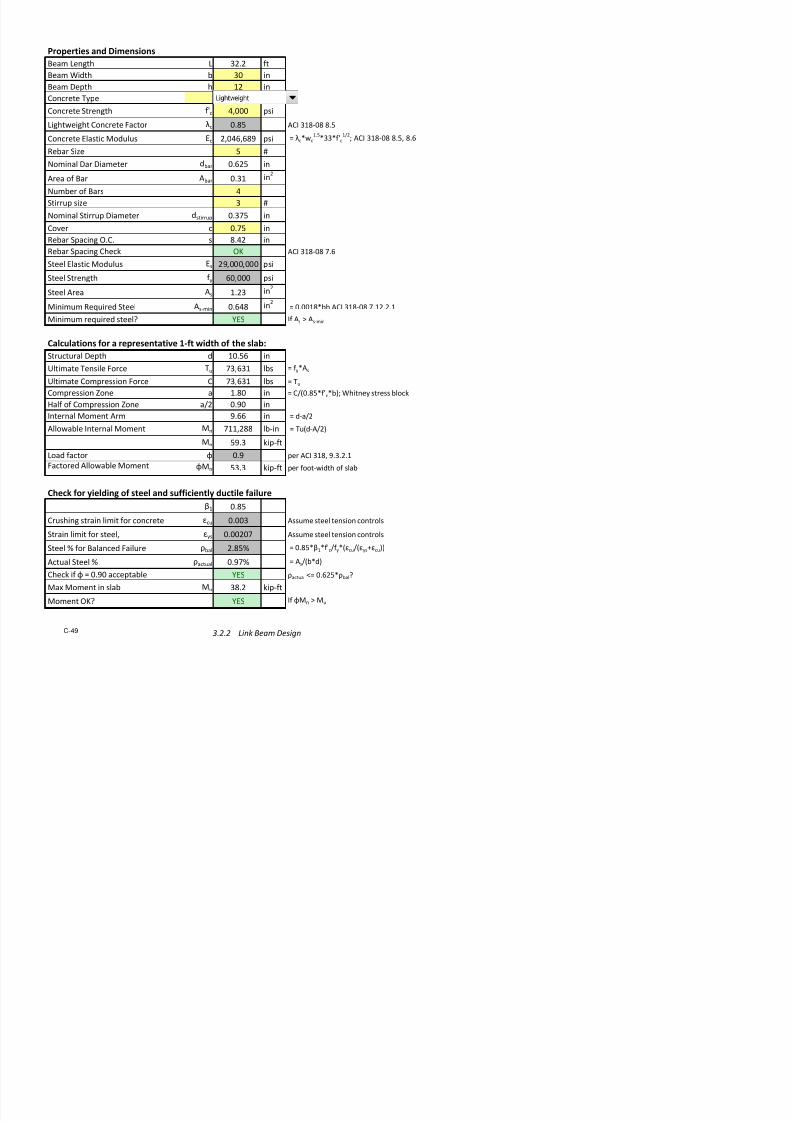
7/17/2019 Structural Design Project of Super Tall Building Chicago Spire
http://slidepdf.com/reader/full/structural-design-project-of-super-tall-building-chicago-spire 216/474
93 "e#idential 3.60E 03 1224.50 5.40E 09 0.00900 59.07 4!301 1!66!946
92 "e#idential 3.60E+03 1211.33 5.2E+09 0.001 57.0 4!359 1!725!574
91 "e#idential 3.60E+03 119.17 5.17E+09 0.0062 56.55 4!415 1!72!962
90 "e#idential 3.60E+03 115.00 5.06E+09 0.0043 55.32 4!471 1!41!096
9 "e#idential 3.60E+03 1171.3 4.94E+09 0.0024 54.10 4!525 1!99!957
"e#idential 3.60E+03 115.67 4.3E+09 0.0006 52.9 4!577 1!959!531
7 "e#idential 3.60E+03 1145.50 4.73E+09 0.007 51.69 4!629 2!019!01
6 "e#idential 3.60E+03 1132.33 4.62E+09 0.00770 50.51 4!60 2!00!752
5 "e#idential 3.60E+03 1119.17 4.51E+09 0.00752 49.34 4!729 2!142!36
4 "e#idential 3.60E+03 1106.00 4.40E+09 0.00734 4.19 4!777 2!204!634
3 "e#idential 3.60E+03 1092.3 4.30E+09 0.00717 47.05 4!24 2!267!534
2 "e#idential 3.60E+03 1079.67 4.20E+09 0.00700 45.92 4!70 2!331!0531 "e#idential 3.60E+03 1066.50 4.10E+09 0.0063 44.1 4!915 2!395!177
0 "e#idential 3.60E+03 1053.33 4.00E+09 0.00666 43.71 4!959 2!459!91
79 "e#idential 3.60E+03 1040.17 3.90E+09 0.00649 42.62 5!001 2!525!11
7 "e#idential 3.60E+03 1027.00 3.0E+09 0.00633 41.55 5!043 2!591!032
77 "e#idential 3.60E+03 1013.3 3.70E+09 0.00617 40.49 5!03 2!657!430
76 "e#idential 3.60E+03 1000.67 3.61E+09 0.00601 39.45 5!123 2!724!361
75 "e#idential 3.60E+03 97.50 3.51E+09 0.0055 3.42 5!161 2!791!11
74 $%bby 3.77E+03 974.33 3.5E+09 0.00597 39.19 5!200 2!59!767
3.0
Gravity Design
3.1 Tributary Areas 33
3.2
Core Area
3.2.1
Concrete Slab Design 39
3.2.2
Link Bea Design !"
3.3 #loor Area "1
3.3.1
Co$osite Decking
3.3.1.1
Composite Decking Design 52
3.3.1.2 Composite Decking Hand-Calc. and Mastan Analysis 56
3.3.2 Co$osite Bea Design

7/17/2019 Structural Design Project of Super Tall Building Chicago Spire
http://slidepdf.com/reader/full/structural-design-project-of-super-tall-building-chicago-spire 217/474
3.3.2
Co$osite Bea Design
3.3.2.1 Joist Design Tool 64
3.3.2.2
adial !i"de"s 6#
3.3.2.3 otated adial !i"de" $eam Design ##
3.3.2.4 Ci"c%m&e"ential !i"de" Design '(
3.3.2.5 Cantile)e"s '3
3.3.2.6
H** +dge $eam Design ''
3.3.3
%ibration Analysis 93
3.! Coluns 99
3.!.1 Colun Loa& Take&o'n 100
3.!.2
Co$osite Colun Design 11!
Tributary Areas Calculations Chung Yu Wang
11/6/2011
Title: Tributary Area and Sizing of Flexural Elements under Uniformly Distributed Load for Bank 1,
Residential (5th
floor).
7/17/2019 Structural Design Project of Super Tall Building Chicago Spire
http://slidepdf.com/reader/full/structural-design-project-of-super-tall-building-chicago-spire 218/474
Figure 1: Typical Tributary Areas
Assumptions:
1) Except for elements in Bank 4, all elements in same bank have the same tributary area and
geometry if they are located at the same location of each floor.
2) The tributary areas of the joists are technically trapezoidal in shape, but we assume the tributary
area to be rectangular in shape with the width of the rectangle to be the base length of the
trapezoid.
3) HSS are load bearing members.
4) Angled Girder takes ½ of the tributary area and load from the following area, and HSS 1 takes ¼
of the tributary and load from the same area.
Tributary Areas Calculations Chung Yu Wang
11/6/2011
Figure 2: HSS-AG Tributary Area
5) To estimate the area of the HSS-AG tributary area, we use Revit and rotate the slab so point B
meets point A. The corner of the slab is at the end of the cantilevering girder. Use straight
sketch lines to draw a boundary that encloses the area and take length measurements to find
the approximate, larger than actual, area.
6) The distances from columns to façade and from girder to façade are held constant throughout
the building.
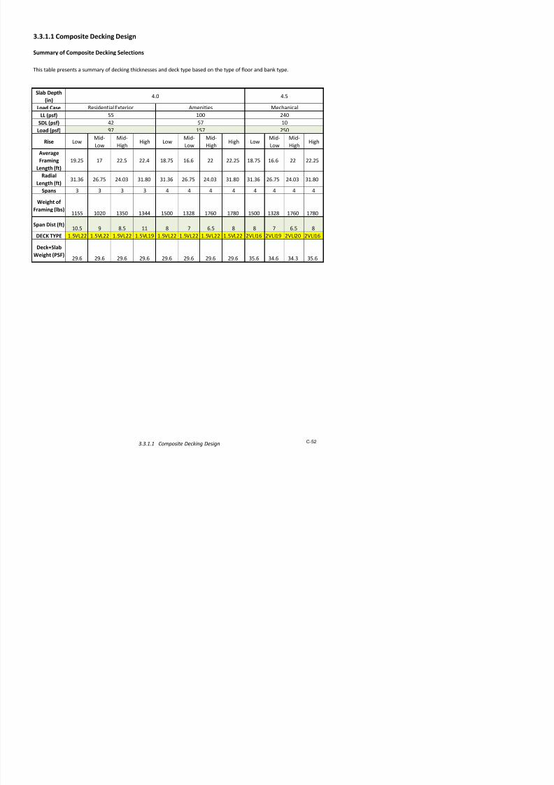
7/17/2019 Structural Design Project of Super Tall Building Chicago Spire
http://slidepdf.com/reader/full/structural-design-project-of-super-tall-building-chicago-spire 219/474
J1L 188in pCJ1 103i
J2L 229in
pJ1J2 136in
b pCJ1 pJ1J2
2119.5i
wJ1L J2L
2208.5i
Area b w 173.026ft2
GL 270in J2L 229in
pJ2G 137i pJ1J2 136in
b pJ1J2 pJ2G
2136.5i
Tributary Areas Calculations Chung Yu Wang
11/6/2011
Girder, G of Floor G (Floor Plan Given)
GL 245in
SF 282in
pJ2G 109i
pCG 813i
pGSF pCG
GLSF pCG
122.78in
Area SF GL
2
pJ2G pGSF
2
212.062ft
2

7/17/2019 Structural Design Project of Super Tall Building Chicago Spire
http://slidepdf.com/reader/full/structural-design-project-of-super-tall-building-chicago-spire 220/474
Tributary Areas Calculations Chung Yu Wang
11/6/2011
Girder, G of Floor 5 (Bank 1)
Assume pGSF, distance from girder to exterior isheld constant throughout the building
GL 270in
pGSF 122in
pCG 896i
pJ2G 137i
SF GL
pCG
pCG pGSF( ) 306.763i
Area SF GL
2
pJ2G pGSF
2 259.343ft
2

7/17/2019 Structural Design Project of Super Tall Building Chicago Spire
http://slidepdf.com/reader/full/structural-design-project-of-super-tall-building-chicago-spire 221/474
Tributary Areas Calculations Chung Yu Wang
11/6/2011
Angled Girder, AG of Floor 60 (Bank 2)
Assume AG takes 1/2 of this total area
A 295in
B 144i
C 291i
D 142in
E 212i
AGL 303i
A1 B C 4.19 104
in2
A2 D C2
A B( ) 3.269 104 in2
AreaAGA1 A2
259 012ft2

7/17/2019 Structural Design Project of Super Tall Building Chicago Spire
http://slidepdf.com/reader/full/structural-design-project-of-super-tall-building-chicago-spire 222/474
Angled Girder, AG of Floor 5 (Bank 1)
AreaAG2
259.012ft
GL 270in
GL60 245i
Factor
GL
GL601.102
AreaAG60 373 46in2
AreaAG Factor Area AG60 285.811ft2
AGL60 303i
Tributary Areas Calculations Chung Yu Wang
11/6/2011
HSS1 of Floor 5
HSS 1 is the perimeter element that is taking part
of the tributary area. We assume that HSS1 has ¼
of the area or ½ that of the angled girder on the
same floor.
HSS2 of Floor 5
HSS1AreaAreaAG
2142.906ft
2

7/17/2019 Structural Design Project of Super Tall Building Chicago Spire
http://slidepdf.com/reader/full/structural-design-project-of-super-tall-building-chicago-spire 223/474
pGSF 122in
SF 307in
Area pGSF
2
SF 130.049ft2
C r e a t e d b y : A D V
1 1 / 3 0 / 2 0 1 1
S D
M
a x M ! m e n t
" n d R e a t $ ! n
R e b a r
R e b a r D $ % t &
p % ( )
' p % ( )
' * $ p + ( t )
' * $ p % / ( t , w $ d t h )
#
' $ n -
! & & )
0 0
3 & .
2
1 &
0
1
0 0
2 & 3
3
1 & 2
0
1 8
0 0
& 8
2
2 & 2
0
.
0 0
2 &
2
1 & 2
0
1 8
0
1 0
& .
2 & 3
1 2
0
1 0
3 & .
3
1 & 8
8
1 8
0
1 0
1 2 & 2
0
3 &
.
0
1 0
3 &
8
1 &
1
1 8
e r e d e % $ 5 n e d 4 % $ n 5 t h
e t ! ! l a n d t h e $ n ( ! r m a t $ ! n ( r ! m
t h ! % e r e % 4 l t % $ %
a n d e n d % r e a t $ ! n % a
r e a l 4 l a t e d 4 % $ n 5 ( a t ! r e d l ! a
d % &
B a n k 1
2 . 1
C o n c r e t e S l a b D e
s i g n

7/17/2019 Structural Design Project of Super Tall Building Chicago Spire
http://slidepdf.com/reader/full/structural-design-project-of-super-tall-building-chicago-spire 224/474
3 . 2 . 1
C o n c r e t e S l a b
D e s i g n
D e s i g n e d S l a b I n f o r m a t i o n
M m a x = w l 2 / 8
R x n = w l / 2
S l a b #
S p a n
S l a b D e p t h
D
' ( t )
' $ n )
' p % ( )
' p
R e % $ d e n t $ a l / ! b b y
1
1 0 & 1
.
.
& 0
1
2
8 & 2
.
& 0
1
3
1 &
0
.
& 0
1
8 &
0
.
& 0
1
M e h a n $ a l
1
1 0 & 2
.
& 0
2
2
8 & 3
.
& 0
2
3
1 &
.
& 0
2
8 &
.
& 0
2
h $ % % h e e t d $ % p l a y % t h e r e % 4 l t % ( r ! m 4
% $ n 5 t h e % l a b t ! ! l &
A l l % l a b % w e
t a b 4 l a t e d b e l ! w &
h e l !
a d % % h ! w n a r e 4 n ( a t ! r e d &
h e
m ! m e n t %
6 ! r m 4 l a % 7 % e
d
3 . 2
C-39
S D
M
a x M ! m e n t
" n d R e a t $ ! n
R e b a r
R e b a r D $ % t &
p % ( )
' p % ( )
' * $ p + ( t )
' * $ p % / ( t w $ d t h )
#
' $ n -
! & & )
1 0 0
3 & .
2
1 &
0
1
1 0 0
2 & 3
3
1 & 2
0
1 8
1 0 0
& 8
2
2 & 2
0
.
1 0 0
2 &
2
1 & 2
3
1 8
2 0
1 0
& .
2 & 3
1 2
2 0
1 0
3 & .
3
1 & 8
8
1 8
2 0
1 0
1 2 & 2
0
3 &
.
2 0
1 0
3 &
8
1 &
1
1 8
S D
M
a x M ! m e n t
" n d R e a t $ ! n
R e b a r
R e b a r D $ % t &
p % ( )
' p % ( )
' * $ p + ( t )
' * $ p % / ( t w $ d t h )
#
' $ n -
! & & )
1 0 0
3 & .
2
1 &
0
1
1 0 0
1 & 2
0
0 & 8
.
1 8
1 0 0
1 & 2
0
0 & 8
.
1 8
1 0 0
2 & 0
1 & 1
3
1 8
2 0
1 0
& .
2 & 3
8
2 0
1 0
1 & 8
1 & 3
1 8
2 0
1 0
1 & 8
1 & 3
1 8
2 0
1 0
3 & 2
2
1 &
1 .
B a n k 2
B a n k 3
2 . 1
C o n c r e t e S l a b D e
s i g n

7/17/2019 Structural Design Project of Super Tall Building Chicago Spire
http://slidepdf.com/reader/full/structural-design-project-of-super-tall-building-chicago-spire 225/474
S l a b #
S p a n
S l a b D e p t h
D
' ( t )
' $ n )
' p % ( )
' p
R e % $ d e n t $ a l / ! b b y
1
1 0 & 1
.
.
& 0
1
2
8 & 2
.
& 0
1
3
1 &
0
.
& 0
1
8 &
0
.
& 0
1
M e h a n $ a l
1
1 0 & 2
.
& 0
2
2
8 & 3
.
& 0
2
3
1 &
.
& 0
2
8 &
.
& 0
2
S l a b #
S p a n
S l a b D e p t h
D
' ( t )
' $ n )
' p % ( )
' p
R e % $ d e n t $ a l / ! b b y
1
1 0 & 1
.
.
& 0
1
2
. & 0
.
.
& 0
1
3
. & 0
.
.
& 0
1
& 8
0
.
& 0
1
M e h a n $ a l
1
1 0 & 1
.
.
& 0
2
2
. & 0
.
.
& 0
2
3
. & 0
.
.
& 0
2
& 8
0
.
& 0
2 3 . 2
C-40
S D
M
a x M ! m e n t
" n d R e a t $ ! n
R e b a r
R e b a r D $ % t &
p % ( )
' p % ( )
' * $ p + ( t )
' * $ p % / ( t w $ d t h )
#
' $ n -
! & & )
1 0 0
3 & .
2
1 &
0
1
1 0 0
1 & 2
0
0 & 8
.
1 8
1 0 0
1 & 2
0
0 & 8
.
1 8
1 0 0
3 & .
1 &
0
1
S D
M
a x M ! m e n t
" n d R e a t $ ! n
R e b a r
R e b a r D $ % t &
p % ( )
' p % ( )
' * $ p + ( t )
' * $ p % / ( t w $ d t h )
#
' $ n -
! & & )
1 0 0
3 & .
2
1 &
0
1
1 0 0
+ +
+ +
+ +
+ +
1 0 0
+ +
+ +
+ +
+ +
1 0 0
3 & .
1 &
0
1
B a n k 4 . 1
B a n k 4 . 2
2 . 1
C o n c r e t e S l a b D e
s i g n

7/17/2019 Structural Design Project of Super Tall Building Chicago Spire
http://slidepdf.com/reader/full/structural-design-project-of-super-tall-building-chicago-spire 226/474
S l a b #
S p a n
S l a b D e p t h
D
' ( t )
' $ n )
' p % ( )
'
R e % $ d e n t $ a l / ! b b y
1
1 0 & 1
.
.
& 0
1
2
. & 0
.
.
& 0
1
3
. & 0
.
.
& 0
1
1 0 & 1
8
.
& 0
1
S l a b #
S p a n
S l a b D e p t h
D
' ( t )
' $ n )
' p % ( )
'
R e % $ d e n t $ a l / ! b b y
1
1 0 & 1
.
.
& 0
1
2
+ +
.
& 0
1
3
+ +
.
& 0
1
1 0 & 1
8
.
& 0
1 3 . 2
C-41
C r e a t e d b
y : A D V
1 1 / 3 0 / 2 0 1 1
C o l o r K e y :
U s e r I n p u t
C o n s t a n t / ! r e " o u s C a l c #
C a l c / L o o k u p
& e
! a s s e s C ' e c k
( o
) a l s C ' e c k
p t
+ - a ,
k p t
n d 4 , n k p s
4 e b a r %
4 e b a r o # c #
n
p t
3 # .
3
1 # .
.
1 .
8 8
p l
$ n 9 l e e n d
1 .
2 2
l b s
1 8 0
p l
1 # .
k p s
L
8 ; # .
p l
r e t e s l a b
9 " e n t ' e n e
c e s s a r y n o r - a t o n #
F a c t o r e d L o a d i n g ( 1 . 2 D L + 1 . L L !
R e s " l t a n
t # n d r e a c t i o n ( f a c t o r e d !
I - p o r t a n t
I n o r - a t o n
2 . 1
C o n c r e t e S l a b D e
s i g n

7/17/2019 Structural Design Project of Super Tall Building Chicago Spire
http://slidepdf.com/reader/full/structural-design-project-of-super-tall-building-chicago-spire 227/474
R e i n f o r c e d C o n c r e
t e S l a b D e s i g n
B a n k
1
L o c a t o n
1
$ l a b %
1
* K
+ a , + o - e n t n $ l a b
3 # .
3
k p
+
a , A l l o 5 a b l e + o - e n t
3 # 6
k p
L o a d s
D L
7 7 # 0
p l
D L
L L
1 0 0
p l
L L
$ D L
7 6
p l
$ D
O v e r a l l S l a b C h e c k
< ' s s ' e e t s a t o o l t o d e
s 9 n a s - p l y s u p p o r t e d r e n o r c e d c o n c
U n f a c t o r e d L o a d i n g
3 .
C-42
2 2 2 s s np
t
p t
E 5
c 1 # 7
E 3 3 E >
c 1 / 2
F A C I 3 1 ; 0 ; ; # 7
; # 8
A s s u - e d $ a n d
L 9 ' t 5 e 9 ' t C o n c r e t e
' c d
/ 2
y E A
s
<
u
C / 0
# ; 7 E > c E b F G ' t n e y s t r e s s b l o c k
<
u d a
/ 2
A C I 3 1 ;
= # 3 # 2 # 1
p e r o o t 5 d t ' o s l a b
A C I 3 1 ; 0 ; 6 # 8
1 2 E A b
/ s
0 # 0
0 1 ; E b ' F A C I 3 1 ; 0 ; 6 # 1
2 # 2 # 1
A s
H A
s - n
. 2 . 1
C o n c r e t e S l a b D e
s i g n

7/17/2019 Structural Design Project of Super Tall Building Chicago Spire
http://slidepdf.com/reader/full/structural-design-project-of-super-tall-building-chicago-spire 228/474
$ a s i c S l a b % r o & e r t i e s
$ p a n l e n 9 t '
L
= # 8
8
t
$ l a b d e p t '
'
8
n
C o n c r e t e t y p e
1
C o n c r e t e s t r e n 9 t '
> c
. 0 0 0
p s
C o n c r e t e + o d u l u s o l a s t c t y
c
2 0 . 8
8 ; =
p s
4 e b a r s ? e
%
.
( o - n a l b a r d a - e t e r
d b a r
0 # 7
n
A r e a o b a r
A b a r
0 # 2
0
n 2
4 e b a r s p a c n 9 o # c #
s
1 .
n
4 e b a r $ p a c n 9 C ' e c k
* K
$ t e e l l a s t c + o d u l o u s
s
2 = 0 0
0 0
0 0
p s
$ t e e l $ t r e n 9 t '
y
8 0 0
0 0
p s
A r e a o s t e e l p e r o o t 5
d t '
A s
0 # 1
6
n 2
+ n - u - r e @ u r e d s t e e
l a r e a
A s - n
0 # 1 3 0
n 2
A r e a o s t e e l a c c e p t a b l e
&
$
C a l c " l a t i o n s f o r a R e &
r e s e n t a t i v e 1 ' f t i d t h o f t h
e S l a b )
C o n c r e t e c o " e r
c
0 # 6
7
n
$ t r u c t u r a l d e p t '
d
7 # 0
0
n
U l t - a t e t e n s l e o r c e
< u
1 0 0
= ;
l b s
U l t - a t e c o - p r e s s o n o r c e
C
1 0 0
= ;
l b s
C o - p r e s s o n ? o n e
a
0 # 2
7
n
1 / 2 o C o - p r e s s o n ? o n
e
a / 2
0 # 1
2
n
I n t e r n a l - o - e n t a r -
d a
/ 2
. # ;
;
n
A l l o 5 a b l e n t e r n a l - o -
e n t
+ n
. = 2
. 0
l b
A l l o 5 a b l e n t e r n a l - o -
e n t
+ n
. # 1
0
k p
L o a d a c t o r
0 # =
) a c t o r e d A l l o 5 a b l e + o - e n t
+
n
3 # 8
=
k p 3
C-43
e p t
A C I 1 0 # 2 # 6 # 3
A s s u - e s t e e l t e n s o n c o n t r o l s
A s s u - e s t e e l t e n s o n c o n t r o l s
0 # ;
7 E
1 E > c / y
E J
c u / J
s t e e
l N J
c u
A
s t e e
l / b E d
I & e s 0 # =
3 . 2 . 1
C o n c r e t e S l a b D e
s i g n

7/17/2019 Structural Design Project of Super Tall Building Chicago Spire
http://slidepdf.com/reader/full/structural-design-project-of-super-tall-building-chicago-spire 229/474
C h e c k f o r * i e l d i n g o f S t e e l a n d S " f f i c i e n t l D " c t i l e F a i l " r e
C o n c r e t e C o - p r e s s " e A r e a ) a c t o r
1
0 # ;
7
C r u s ' n 9 s t r a n l - t o r
c o n c r e t e
J c u
0 # 0 0 3
$ t r a n l - t o r s t e e l
J y s
0 # 0 0
2 0 6
! e r c e n t s t e e l o r b a l a n c
e d a l u r e
b a l
2 # ; 7
A c t u a l p e r c e n t s t e e l
a c t u a l
0 # 2 ;
a c t u a l
M 0 # 8
2 7 E b a l
&
$
+ a , + o - e n t n s l a b
+ u
3 # .
3
k p
+ u
M +
n
&
$
3
C-44
3.2.2 Link Beam Design Created by: CJB, ADV 5/10/2012
Table 9.6: Link Beam DimensionsLength Tributary Area Curvature, α Radius, r
(ft) (ft2) (deg) (ft)
1 31 120 -- --
2 9.34 84 -- --
3 32.2 484 42 40
4 18.3 110 -- --
5 40.6 9.9 -- --
1 31 120 -- --
2 9.34 84 -- --
3 32.2 484 42 40
4 18 3 110
Bank 1
Bank 2
!"#$ $"eet $%&&ar#'e$ t"e re *#+ bea&$. !"e d#&e+$#+$ fr bea&$ #+ ea" ba+ are -re$e+ted #+
!ab*e 9.6. !ab*e 9. $%&&ar#'e$ t"e re#+fr#+g $tee* deta#*$ fr ea" re$#de+t#a* a+d *bby bea&. te
t"at t"e re$#de+t#a* a+d *bby bea&$ "ae t"e $a&e de$#g+ #t"#+ ea" ba+. !ab*e 9.8 $%&&ar#'e$ t"e
&e"a+#a* f*r *#+ bea&$.
Beam #

7/17/2019 Structural Design Project of Super Tall Building Chicago Spire
http://slidepdf.com/reader/full/structural-design-project-of-super-tall-building-chicago-spire 230/474
4 18.3 110 -- --
5 40.6 9.9 -- --
1 11.2 5.6 -- --
2 9.34 0.9 -- --
3 13.2 122 43 15.4
4 14 65.2 -- --
5 40.6 9.9 -- --
1 9.65 65.2 -- --
2 9.65 120 -- --
3 12.9 92.3 -- --
4 9.68 40.3 -- --
5 40.6 9.9 -- --
1 -- -- -- --
2 9.65 9.9 -- --
3 -- -- -- --
4 9 68 2 9
Bank 3
Bank 4.1
Bank 4.2
Table 9.7: Residential and Lobby Link Beam Summary
b h sstirru
(#+) (#+) (#+)
1 16 16 9 6 3 .2
2 6 10 9 2 3 4.2
3 48 16 9 20 4 .14 10 16 9 3 4 .1
5 20 16 9 6 4 .1
1 16 16 9 6 3 .2
2 6 10 9 2 3 4.2
3 48 16 9 20 4 .1
4 10 16 9 3 4 .1
5 20 16 9 6 4 .1
1 6 12 9 2 3 5.2
2 6 10 9 2 3 4.2
3 28 16 9 11 3 .2
4 10 10 9 2 3 4.2
Bank 3
Bank 2
Beam ! bar ! nbar stirru !
Bank 1

7/17/2019 Structural Design Project of Super Tall Building Chicago Spire
http://slidepdf.com/reader/full/structural-design-project-of-super-tall-building-chicago-spire 231/474
5 20 16 9 6 4 .1
1 8 8 9 2 3 3.2
2 8 10 9 2 3 4.2
3 30 16 9 10 4 .1
4 8 6 9 2 3 2.2
5 20 16 9 6 3 .2
1
2 8 10 9 2 3 4.23
4 8 6 9 2 3 2.2
5 20 16 9 6 3 .2
Bank 4.2
Bank 4.1
Table 9.8: Mechanical Link Beam Summary
b h sstirru
(#+) (#+) (#+)
1 22 16 9 6 3 .2
2 8 10 9 2 3 4.2
3 2 16 9 20 4 .1
4 12 16 9 3 4 .1
5 24 16 9 6 4 .1
1 22 16 9 6 3 .2
2 8 10 9 2 3 4.2
3 2 16 9 20 4 .1
4 12 16 9 3 4 .1
5 24 16 9 6 4 .1
1 10 10 9 2 3 4.2
2 8 10 9 2 3 4.2
3 48 16 9 11 3 .2
4 10 10 9 2 3 4.2
Beam ! bar ! nbar stirru !
Bank 3
Bank 2
Bank 1

7/17/2019 Structural Design Project of Super Tall Building Chicago Spire
http://slidepdf.com/reader/full/structural-design-project-of-super-tall-building-chicago-spire 232/474
5 24 16 9 6 4 .1
1 10 8 9 2 3 3.2
2 10 10 9 2 3 4.2
3 12 10 9 10 3 4.2
4 8 8 9 2 3 3.2
5 24 16 9 6 3 .2
1
2 8 10 9 2 3 4.23
4 6 8 9 2 3 3.2
5 24 16 9 6 3 .2
Bank 4.2
Bank 4.1
C r e a t e d b y :
T S
1 1 / 3 0 / 2 0 1 1
u d e s t h e e f f e c t s o f t o r s i o n
f o r c u r v e d b e a m s .
C o l o r " e y :
# s e r $ n %
u t
C o n s t a n
t / ' r e v i o u s C a l c .
C a l c / & o o ! u %
) e s
' a s s e s C
h e c !
* o
+ a i l s C h e c
- u
! i %
f t
n d 4 n ! i % s
a r (
a r S % a c i n g i n
3 . 2
8 . 9
7
. 8 2
. 0
% l f
8 , 9 8 0
l b
0
% l f
8 . 9 8
! i % s
. 8
% l f
8
% l f
$ m % o r t a n t $ n f o r m a t i o n
L o a d i n g ( 1 . 2 D 1 . ! L "
# n d r e a c t i o n
( f a c t o r e d "
3 . 2 . 2
L i n k B e a m D
e s i g n

7/17/2019 Structural Design Project of Super Tall Building Chicago Spire
http://slidepdf.com/reader/full/structural-design-project-of-super-tall-building-chicago-spire 233/474
R e i n f o r c e d C o n c r e t e B e a m D
e s i g n
T h i s s h e e t i s u s e d t o d e s i g n r e i n f o r c e d c o n c r e t e b e a m s , a
n d i n c l u
a n ! :
1
& o c a t i o n :
1
e a m (
3
O v e r a l l C h
e c k :
"
- a - o m e n t i n S l a b :
3 . 2
! i % f t
- a 5 l l o 6 a b l e - o m
e n t :
7 3 . 3
! i % f t
&
7 7 % l f
&
; ; .
& &
1 0 0 % l f
& &
1 ;
S &
7 9 % l f
S &
; .
6
2 < 8
U n f a c t o r e d L
o a d i n g
F a c t o r e d L
C-48
#ro$erties and DimensionsBeam Length L 3$.$ ft
Beam 0idth b 3 in
Beam *e%th h 1$ in
oncrete T2%e 1
oncrete "trength fc , %si
Light(eight oncrete 4actor 5c .) '6 31& .)
oncrete 7lastic odulus 7c $,+,+/ %si 8 5c9(c
1.)
9339fc1$
; '6 31& .), .+<ebar "i=e ) #
>ominal *ar *iameter dbar .+$) in
'rea of Bar 'bar .31 in$
>umber of Bars
"tirru% si=e 3 #
>ominal "tirru% *iameter dstirru% .3-) in
over c .-) in<ebar "%acing O.. s .$ in
<ebar "%acing heck OK '6 31& -.+
"teel 7lastic odulus 7s $/,, %si
"teel "trength f 2 +, %si
"teel 'rea 's 1.$3 in$

7/17/2019 Structural Design Project of Super Tall Building Chicago Spire
http://slidepdf.com/reader/full/structural-design-project-of-super-tall-building-chicago-spire 234/474
inimum <e?uired "teel 's&min .+ in$
8 .19bh '6 31& -.1$.$.1
inimum re?uired steel@ A7" 6f 's 's&min
Calc%lations for a re$resentative 1&ft 'idth of the sla(:
"tructural *e%th d 1.)+ in
Cltimate Tensile 4orce Tu -3,+31 lbs 8 f 29's
Cltimate om%ression 4orce -3,+31 lbs 8 Tu
om%ression Done a 1. in 8 E.)9fc9bF; 0hitne2 stress block
Galf of om%ression Done a$ ./ in
6nternal oment 'rm /.++ in 8 d&a$
'llo(able 6nternal oment n -11,$ lb&in 8 TuEd&'$F
n )/.3 ki%&ft
Load factor H ./
4actored 'llo(able oment Hn )3.3 ki%&ft %er foot&(idth of slab
Check for )ielding of steel and s%fficientl) d%ctile fail%re
I1 )
%er '6 31, /.3.$.1
*+,-R '6 31& "ection 11.$
"tructural *e%th d 1.)+ in
"hear at face of su%%ort .- ki%s
a!imum *esign "hear u,ma! . ki%s 8 & (9d
"hear <eduction 4actor Hv .-)
'llo(able "hear c . ki%s 8 $PEfcF9b9d; '6 31 11&3
<educed 'llo(able "hear Hvc 3.+ ki%s
.OR*/O0 '6 31& "ection 11.)
radius of curvature r . ft
angle of curvature Q .-3 rad
factored distributed load ( $/ %lf
4actored Torsion at ends Tu )/.1 ki%&ft 8 r$(9EQ9sinEQF & Q$ M sinEQ$F; see belo(
<eduction 4actor Hb ./4le!ural <esistance <fle! 1)$ %si 8 u EHbb(d
$F
'ngle of T(ist R .-$ rad 8 r$( E7c<fle!F; see belo(
'rea of Serimeter oncrete 'c% 3/+ in$
8 b9h M Eh & +F9+; '6 31 11.)
Outer Serimeter of ross§ion %c% /+ in 8 $9Eb M $h & +F; '6 31 11.)
Threshold Torsion Tth +.)/ ki%&ft 8 H5PEfcF9E'$
c%%c%F; '6 31 11.).1EaF

7/17/2019 Structural Design Project of Super Tall Building Chicago Spire
http://slidepdf.com/reader/full/structural-design-project-of-super-tall-building-chicago-spire 235/474
th % c c% c%
ust heck Torsion@ A7"
'rea 7nclosed b2 Torsion <einf. 'oh $) in$
8 Eh & $c & dstirru%F9Eb & $c & dstirru%F; '6 31 11.)
Serimeter of Torsion <einf. %ch - in 8 $9Eh & $c M b & $cF; '6 31 11.)
'%%lied Torsional "tress Ta%%lied . ksi PEEubdF$ M ETu%h1.-'
$ohF
$F; '6 31 11.).3EaF
Torsional "trength Tstrength .)+/ ksi 8 HEcbd M PEfcFF; '6 31 E11&1F
6s the section large enough@ A7"
<eference:
Blodgett, Omer 0. Design of Welded Structures
6f Tstrength Ta%%lied
6f Tu Tth
3.3
#loor Area "1
3.3.1
Co$osite Decking
3.3.1.1 Composite Decking Design 52
3.3.1.2 Composite Decking Hand-Calc. and Mastan Analysis 56
3.3.2
Co$osite Bea Design
3.3.2.1 Joist Design Tool 64
3.3.2.2 adial !i"de"s 6#
3.3.2.3 otated adial !i"de" $eam Design ##
3.3.2.4
Ci"c%m&e"ential !i"de" Design '(
3.3.2.5 Cantile)e"s '3
3.3.2.6 H** +dge $eam Design ''
3 3 3 %ibration Analysis 93
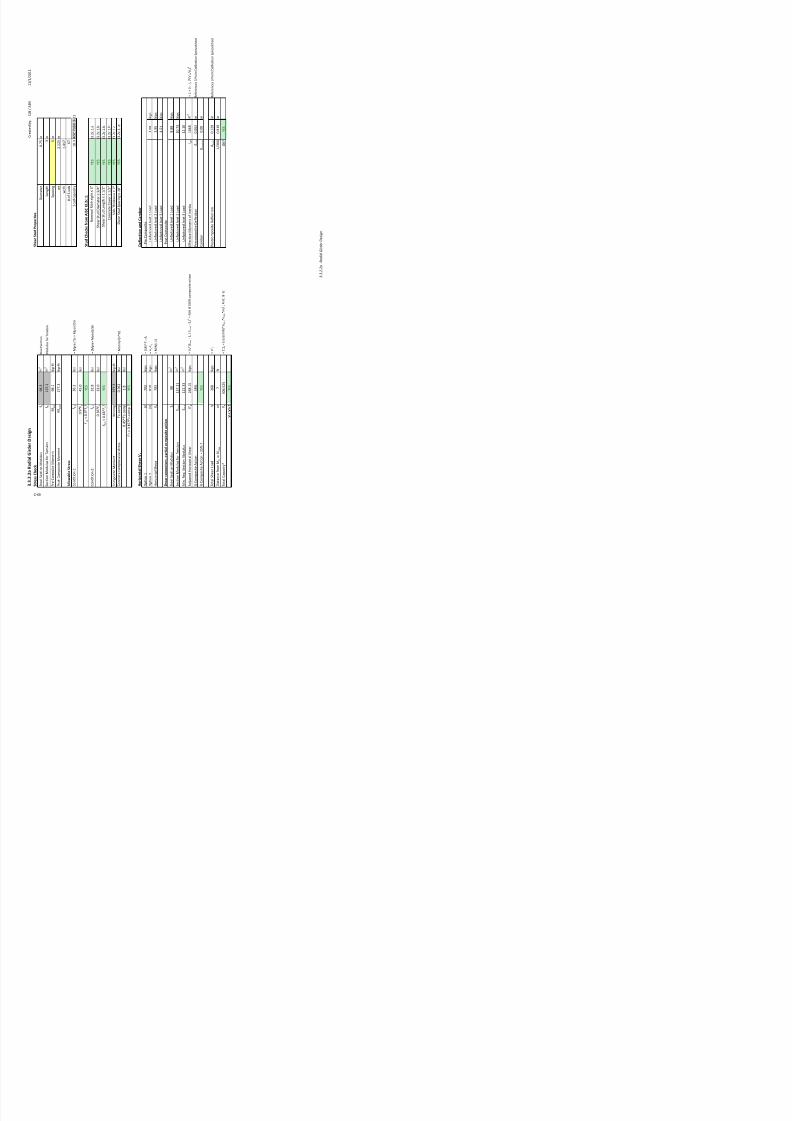
7/17/2019 Structural Design Project of Super Tall Building Chicago Spire
http://slidepdf.com/reader/full/structural-design-project-of-super-tall-building-chicago-spire 236/474
3.3.3
%ibration Analysis 93
3.3.1.1 Composite Decking Design
Summary of Composite Decking Selections
Slab Depth
(in)Load Case
LL (psf)
SDL (psf)
Load (psf)
Rise Low Mid-
Low
Mid-
High High Low
Mid-
Low
Mid-
High High Low
Mid-
Low
Mid-
High High
!erage
"ramingLength (ft)
19.25 17 22.5 22.4 18.75 16.6 22 22.25 18.75 16.6 22 22.25
Radial
Length (ft) 31.36 26.75 24.03 31.80 31.36 26.75 24.03 31.80 31.36 26.75 24.03 31.80
Spans 3 3 3 3 4 4 4 4 4 4 4 4
#eight of
"raming (lbs)1155 1020 1350 1344 1500 1328 1760 1780 1500 1328 1760 1780
This table !ese"ts a s#$$a!% o& de'(i"g thi'("esses a"d de'( t%e based o" the t%e o& &loo! a"d ba"( t%e.
42
97
)$e"ities
100
57
157
*eside"tial +,te!io!
55
4.0 4.5
Me'ha"i'al
240
10
250

7/17/2019 Structural Design Project of Super Tall Building Chicago Spire
http://slidepdf.com/reader/full/structural-design-project-of-super-tall-building-chicago-spire 237/474
g ( )1155 1020 1350 1344 1500 1328 1760 1780 1500 1328 1760 1780
Span Dist (ft) 10.5 9 8.5 11 8 7 6.5 8 8 7 6.5 8
D$C% &'$ 1.5VL22 1.5VL22 1.5VL22 1.5VL19 1.5VL22 1.5VL22 1.5VL22 1.5VL22 2VLI16 2VLI19 2VLI20 2VLI16
DeckSlab
#eight (S")29.6 29.6 29.6 29.6 29.6 29.6 29.6 29.6 35.6 34.6 34.3 35.6
Low Rise Amenities
DATA
concrete density 110 lb/ft3
f'c of concrete 4 ksi
Ec of concrete 2408 ksi
slab thickness 4.5 in
Number of sans 4
!an len"th 8.0 ft
#/$ interior sans 21.3
%alue &( )E!
#/$ e*terior sans 21.3
%alue &( )E!
!elf +t of concrete slab 41.25 lf
si ,# 5- lf
unfactored ,# 8.25 lf
factored ,#nf12 11-. lf
si ## 100 lf
factored ## nf1 10 lf
dummy ,# 100 lf
dummy ## 100 lf
1) MOMENT CALCULATIONS
A AB B BC C
100 sf ,# on ll !ans 0 0.-08 61.03 0.3543 60.-08
100 sf ## on !an 1 only 0 0.83-1 60.805- 60.03143 60.13-1
100 sf ## on !an 2 only 0 0.042 60.14 0.5-1 60.543
100 sf ## on !an 3 only 0 0.243 60.214 60.00285- 60.543
100 sf ## on !an 4 only 0 0.023-1 60.405- 0.18 60.13-1
Adjust Dummy vaues !o" a#tua oads A AB B BC C
ctual ,# on ll !ans 0 0.-0 61.04 0.35 60.-0
7eak skied ## combination for aboe sketch 0 13 124 24 23
!um of ## moments from critical sans 0 1.13 61.0 0.-- 61.1
,# 9oment * 1.2 0 0.84 61.25 0.42 60.84
## 9oment * 1. 0 1.81 63.04 1.23 61.0
Tota Desi$n Moment %&'( *'+, %'- 1'+ %*'(
9a"nitude of !imle !an :actored 9oment 1.2, ; 1.##2/8
same for all locations0 2.2 62.2 2.2 62.2
<otal ,esi"n 9oment / !imle !an 9 0 1.1 1.3 0.-4 1.23
:actor =m +here <otal ,esi"n 9oment > =m+u?2 0 0.15 0.24 0.0 0.15
<his is a samle calculation to check the deckin" and concrete thickness for the lo+ rise amenities. =alculations
for all other floor tyes +as erformed in the same manner.
,ummy 9oments @isAft/ftB
9oments @isAft/ftB

7/17/2019 Structural Design Project of Super Tall Building Chicago Spire
http://slidepdf.com/reader/full/structural-design-project-of-super-tall-building-chicago-spire 238/474
3.3.1.1 Composite Decking Design
C-53
*) REIN.ORCEMENT BAR CALCULATIONS
A AB B BC C A B C
Rein!o"#in$ Ba"s si/e C3 C4 C C4 C4 1.5%#22 1.5%#22 1.5%#22
rea of one bar s/barin2 0.11 0.2 0.44 0.2 0.2 0.354 0.354 0.354
Dar ,iameterin 0.3-5 0.5 0.-5 0.5 0.5 0.014-5 0.014-5 0.014-5
Ba" Cove"0in) 0.-5 0.-5 0.-5 0.-5 0.-5 0 0 0
!tructural ,eth d in 3.5 3.50 3.38 3.50 3.50 4.4 4.4 4.4
Sa#in$ 2etween 2a"s 0in) 13 13 13 13 13
9a*imum !acin" of bars in 13.5 13.5 13.5 13.5 13.5
Sa#in$ Re3ui"ement O45 )E! )E! )E! )E! )E! )E!
!teel rea in 16ft stri in2 0.10 0.18 0.41 0.18 0.18 0.35 0.35 0.35
9inimum steel areain2/ft 0.10 0.10 0.10 0.10 0.10 0.10 0.10 0.10
9a*imum steel areain2/ft 1.22 1.20 1.15 1.20 1.20 1.54 1.54 1.54
A"ea 2etween t6e imits5 )E! )E! )E! )E! )E! )E! )E! )E!
f y of steelksi 0 0 0 0 0 0 0 0
Es of steelksi 2000 2000 2000 2000 2000 2000 2000 2000
A AB B BC C A B C
<ension force assumin" !teel has yieldedkis .1 11.1 24.4 11.1 11.1 21.2 21.2 21.2
=omression force><ension force .1 11.1 24.4 11.1 11.1 21.2 21.2 21.2
=entroid of com.force a/2Fhitney 9odelin 0.0- 0.14 0.30 0.14 0.14 0.2 0.2 0.2
9oment rm bet+een < G= force in 3.53 3.43 3.23 3.43 3.43 4.3 4.3 4.3
Nominal 9oment =aacity 9n kis6ft 1.8 3.2 . 3.2 3.2 -.- -.- -.-
!tren"th Heduction factor I 0. 0. 0. 0. 0. 0. 0. 0. ssume section Jualifies for I>0.
Usa2e Moment Caa#ity 078Mn)09is%!t) %1'+ *': %,': *': %*': %+': %+': %+':
9oment based on ski loads and factored loads 9 u kis6ft 60.-4 2.5 64.3 1.4 62.- 60.-4 64.3 62.-
?s I9nK9u( )E! )E! )E! )E! )E! )E! )E! )E!
A AB B BC C
!train of the steel at yieldin" Ly 0.0020- 0.0020- 0.0020- 0.0020- 0.0020-
!train of the concreteLcu 0.003 0.003 0.003 0.003 0.003
M1 0.85 0.85 0.85 0.85 0.85
bal 0.0285 0.0285 0.0285 0.0285 0.0285
actual 0.00238 0.00440 0.01003 0.00440 0.00440
?s bal K actual( )E! )E! )E! )E! )E!
?s actualO0.25bal( )E! )E! )E! )E! )E!
Mes6 Tye
Rein!o"#ement Ba"s Ba"s to Mes6
Es of steelksi
.o"#e ; Moment Ca#uations
%eryfin" assumtions for calculations made
!teel rea in 16ft stri in2
9inimum steel areain2/ft
9a*imum steel areain2/ft
A"ea 2etween t6e imits5
f y of steelksi
9esh rea er foot in2
.5<hickness
Cove"0in)
!tructural ,eth d in

7/17/2019 Structural Design Project of Super Tall Building Chicago Spire
http://slidepdf.com/reader/full/structural-design-project-of-super-tall-building-chicago-spire 239/474
3.3.1.1 Composite Decking Design
C-54
-) S<RIN4A=E STEEL BARS
Heinforcin" Dars siPe C4
rea of one bar s/barin2 0.2
Dar ,iameterin 0.5
!acin" bet+een bars in 18
9a*imum !acin" of bars in 18
!acin" HeJuirement &( )E!
!teel rea in 16ft stri in2 0.13
9inimum rea for !hrinka"e Dars in2/ft 0.10
rea "reater than min.reJuirement( )E!

7/17/2019 Structural Design Project of Super Tall Building Chicago Spire
http://slidepdf.com/reader/full/structural-design-project-of-super-tall-building-chicago-spire 240/474
3.3.1.1 Composite Decking Design
C-55

7/17/2019 Structural Design Project of Super Tall Building Chicago Spire
http://slidepdf.com/reader/full/structural-design-project-of-super-tall-building-chicago-spire 241/474

7/17/2019 Structural Design Project of Super Tall Building Chicago Spire
http://slidepdf.com/reader/full/structural-design-project-of-super-tall-building-chicago-spire 242/474

7/17/2019 Structural Design Project of Super Tall Building Chicago Spire
http://slidepdf.com/reader/full/structural-design-project-of-super-tall-building-chicago-spire 243/474

7/17/2019 Structural Design Project of Super Tall Building Chicago Spire
http://slidepdf.com/reader/full/structural-design-project-of-super-tall-building-chicago-spire 244/474

7/17/2019 Structural Design Project of Super Tall Building Chicago Spire
http://slidepdf.com/reader/full/structural-design-project-of-super-tall-building-chicago-spire 245/474

7/17/2019 Structural Design Project of Super Tall Building Chicago Spire
http://slidepdf.com/reader/full/structural-design-project-of-super-tall-building-chicago-spire 246/474

7/17/2019 Structural Design Project of Super Tall Building Chicago Spire
http://slidepdf.com/reader/full/structural-design-project-of-super-tall-building-chicago-spire 247/474
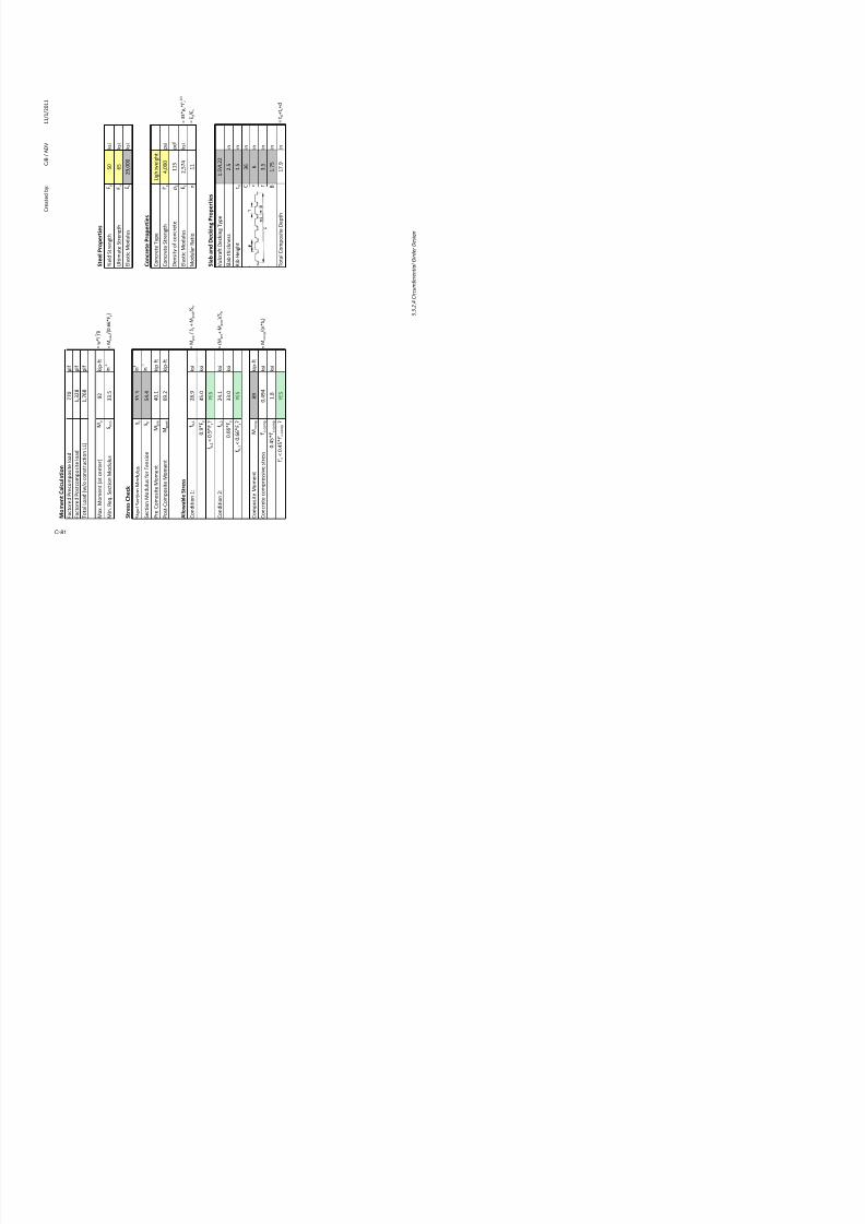
7/17/2019 Structural Design Project of Super Tall Building Chicago Spire
http://slidepdf.com/reader/full/structural-design-project-of-super-tall-building-chicago-spire 248/474
C r e a t e d b y :
1 1 / 1 / 2 0 1 1
f r o m B a n k I n f o r m a t i o n
B e a m p a n
1 ! . "
#
# r o m T o $ e r % e
o m e t r y
B e a m T r ' b u t a r y ( r e a
1 2 "
# t 2
B e a m p a c ' n +
, . 1
#
o r e ' ( o a ' i n g o n ' i t i o n s
m p o s i t e
# r o m l a b 3 e
c k I n # o
l a b a n d 3 e c k ' n +
" 2
p s
B e a m e l # 7 e ' + * t
1
p l #
C o n s t r u c t ' o n L L
2 0
p s
o m p o s i t e
# r o m L o a d u m
m a r y
3 L
! 9
p s
L L
1 0 0
p s #
e ' ( o a ' i n g o n ' i t i o n s
m p o s i t e
l a b a n d 3 e c k ' n +
" , .
p s #
B e a m e l # 7 e ' + * t
1 6 . ,
p l #
C o n s t r u c t ' o n L L
" 2
p s #
o m p o s i t e
3 L
6 , .
p s #
L L
1 6 0
p s
n ' * e a ! t i o n s
m p o s i t e
, a ! t o r e '
3 L
2 . ;
k ' p s
L L
1 . ; 9
k ' p s
T o t a l
. !
k ' p s
o m p o s i t e
3 L
. 2 0
k ' p s
L L
; . , "
k ' p s
T o t a l
1 . 0
k ' p s
p r e d e t e r m ' n e d d e c k ' n + t y p e r u n
n ' n + p e r p e n d ' c u l a r t o t * e
s . & o ' s t n d r e a c t ' o n s a r e u s e d # o
r r a d ' a l + ' r d e r d e s ' + n .
C & B / ( 3
s i g n T o o l

7/17/2019 Structural Design Project of Super Tall Building Chicago Spire
http://slidepdf.com/reader/full/structural-design-project-of-super-tall-building-chicago-spire 249/474
n k :
1
U s e r I n p u t
I n p u t s
p e :
L o b b y
C o n s t a n t / P r e v . C a l c .
m :
& o ' s t 1
C a l c / L o o k u p
B a n k 1
) e s
P a s s e s C * e c
p e
1 2 - 1
o
a ' l s C * e c k
e %
)
& n f a !
t o
a ' l s ' n : o n e
) r e !
o m
u '
4 " 0 5
n g
6
* i $
1
o n
! 0 8
) o s t
! o
7 1
2 - 1
( s
. 1 6
' n
, a ! t o r e
d
1 1 . ;
' n
) r e !
o m
t #
0 . 2 2 !
' n
t $
0 . 2 0
' n
b #
" . ; 9
' n
-
1 . ;
' n "
) o s t
! o
I -
, , . 6
' n
1
p l
J o i s t n
4 a 5
6
' n
) r e !
o m
4 b 5
; 9
' n
b e # #
6
' n
= < I 4 a > b 5
y b
1 2 . 1 6
' n
) o s t
! o
y t
" . 9
' n
o m p
" 1 ;
' n
t r
2 6 . 2
' n "
= I c / y b
c
, !
' n
= I c / y t
n d
* e a r s t u d c o n # ' + u r a t ' o n # o r @ o ' s t s
' n a l l b a n k s a n d # l o o r t y p e s $ ' t * a p
o u n
d ' n T a r a n a t * A s S t e e l , C o n c r e t e , &
C o m p o s i t e D e s i g n o f T a l l B u i l d i n g s
3 . 3 . 2 . 1
J o i s t D e
s
C r e a t e d b y :
1 1 / 1 / 2 0 1 1
C & B / ( 3
) r o p e r t i e s
t r e n + t *
y
! 0
k s '
t e t r e n + t *
u
6 !
k s '
< o d u l u s
s
2 ; > 0 0 0
k s '
e t e ) r o p e r t i e s
t e T y p e
L ' + * t $ e ' + * t
t e t r e n + t *
# A c
> 0 0 0
p s '
y o # c o n c r e t e
F c
1 1 !
p c #
< o d u l u s
c
2 > ! 9
k s '
= " " F c
# A c 0 . !
a r D a t ' o
n
1 1
= s / c
n ' D e ! k i n g ) r o p e r t i e s
t 3 e c k ' n + T y p e
1 . ! L 2 2
' c k n e s s
2 . !
' n
+ * t
t d
1 . !
' n
C
" 6
' n
P
6
' n
T
" . !
' n
B
1 . 9 !
' n
o m p o s ' t e 3 e p t *
1 ! . ;
' n
= t d G t s G d
s i g n T o o l

7/17/2019 Structural Design Project of Super Tall Building Chicago Spire
http://slidepdf.com/reader/full/structural-design-project-of-super-tall-building-chicago-spire 250/474
S t e e l
)
! ,
p l #
) ' e l d
t
1 > , 1
p l #
U l t ' m a t
2 > 1 6 9
p l #
l a s t ' c
<
< u
6 "
k ' p ? # t
= $ l / ,
o n ! r e
m ' n
2 2 . ;
' n
= < m a - / 4 0 . 6 6 y
5
C o n c r e t
C o n c r e t
3 e n s ' t y
s
1 . ;
' n "
l a s t ' c
<
t r
2 6 . 2
' n
< o d u
l a
p r e
1 9 . 0
k ' p ? # t
< o d e l e d a s p ' n ? p ' n
p o s t
! " . !
k ' p ? # t
< o d e l e d a s p ' n ? p ' n
S l a $ a
n
u l c r a
# t
l a b t * '
# b > 1
" , . 2
k s '
= < p r e
/ s
G < p o s t
/ t r
D ' b H e
'
y
! . 0
k s '
y J
)
# b > 2
" 2 . "
k s '
= 4 <
p r e G <
p o s t
5 / t r
y
" " . 0
k s '
y J
)
T o t a l C o
o m p
!
k ' p ? # t
o m p
0 . 6 ,
k s '
= < c o m p
/ 4 n
t 5
o m p
1 . ,
k s '
p J
)
3 . 3 . 2 . 1
J o i s t D e s
C r e a t e d b y :
1 1 / 1 / 2 0 1 1
C & B / ( 3
S t u ' ) r o p e r t i e s
t e r
0 . 9 !
' n
*
" . 0 0
' n
+
6
' n
b s
n r ' b s
" 0
/ r ' b
1
a p a c ' t y
s t u d
1 9 . 2
= M n p e r r ' b N ( I C T a b l e " ? 2 1
u d s
" 0
' t e a c t ' o n
h e ! k s f r o m # I S I 3 . 2 ! . 1
a l D ' b * e ' + * t " Q
)
I " . 2 c . 1 . a
t u d 3 ' a m a t e r " / Q
)
I " . 2 c . 1 . b
t u d L e n + t * R 1 1 / 2 Q
)
I " . 2 c . 1 . b
e t e C o v e r R 1 / 2 Q
)
I " . 2 c . 1 . b
* ' c k n e s s R 2 Q
)
I " . 2 c . 1 . c
t u d p a c ' n + 1 , Q
)
I " . 2 c . 1 . d
e ( o a ' s 5 & n f a ! t o r e ' 6
m p o s ' t e
" "
p l #
o m p o s ' t e
1 2 6
!
p l #
e s i g n T o o l

7/17/2019 Structural Design Project of Super Tall Building Chicago Spire
http://slidepdf.com/reader/full/structural-design-project-of-super-tall-building-chicago-spire 251/474
S h e a r
4 ' 5
" , ;
k ' p
= 0 . , ! # A c
( c
3 ' a m e
t
4 ' ' 5
2 0 ,
k ' p
= ( s y
L e n + t *
*
2 0 ,
k ' p s
= < I 4 ' > ' ' 5
p a c ' n
+
o # D ' b
tio n
s t u d s
/
s
2 2 . ; 1
' n "
t u d c
a
e n s
2 6 . 2 2
' n
o # t u
m ' n
2 2 . ; 1
' n "
A *
1 0 . 1
k ' p s
= *
4
m ' n
? s
/ a v a ' l ? s 5 2 =
/ ( ' # 1 0 0 8 c o m p o s '
! 0 8
)
S t u '
o m ' n
1 0 . 1
k ' p
= A *
* e a r
r ' b s
" 0
* e a r
m
,
# t
C o n c r e
n
2 ! ,
k ' p s
= S M n = 4 s t u d s / r ' b 5 s t u d
n r ' b s m / l N ( I C l a b T
*
n J
)
* e a r
S e r v i !
I e # #
1 6 . "
' n
= I - G 4 I
c ? I -
5 4 A * / *
5 2
P r e C o
I -
, , . 6
' n
P o s t C
o
p r e
0 . 2 0 !
' n
= ! 7 L /
4 " , I 5
b e r
0 . 0 0
' n
p o s t
0 . " 6 "
' n
= ! 7 L /
4 " , I 5
6 0
0 . ! 0 ,
' n
)
e n + t * s b e t $ e e n t * e p o ' n t o #
# K e
r o m o m e n t
3 . 3 . 2 . 1
J o i s t D e
C r e a t e d b y :
C J B / A D V
1 1 / 1 / 2 0 1 1
U s e r I n p u t
I n p u t f r o m a n ! I n f o r m a t i o n
C o n s t a n t / P r e ! o u s C a " # $
% a d ! a " & ! r d e r B e a ' ( p a n :
2 ) $ *
)
+ t
+ r o ' T o , e r & e o ' e t r y
C a " # / L o o k u p
P a s s e s C . e # k
R a d i a l G
i r d e r " o l u m n M o m e n t s
a ! " s C . e # k
P r e # o ' p
o s ! t e
$ 1
k ! p 4 + t
P o s t # o '
p o s ! t e
2 ) ) $ 3
k ! p 4 + t
T o t a " , / o C o n s t r u # t ! o n
3 3 6 $ 7
k ! p 4 + t
+ o i s t R e
a c t i o n L o a d s f o r , + o i s t
T e t f r o m % u m m a r y
/ r e c o m p
o s i t e
J o ! s t 1
J o ! s t 2
J o ! s t 3
D L
2 $ 3
*
3 $ 0
3 $ *
6
k ! p s
L L
1 $
1
2 $ 2
0
2 $ 7
)
k ! p s
/ o s t c o m
p o s i t e
( D L
3 $
)
7 $ )
0
* $ 2
k ! p s
L L
$ 0
*
1 0 $
1 2 $ 3
k ! p s
% l a b a n d D e c ! i n g / r o p e r t i e s
D e # k ! n = T y p e
1 $ * V L
2 2
( " a b t . ! # k n e s s
2 $ *
! n
% ! b e ! = . t
1 $ *
! n
C
3 6 ! n
P
6 ! n
T
3 $ *
! n
B
1 $ )
* ! n
T o t a " C o ' p o s ! t e D e p t .
2 2 $ 1
! n
a n ! # a " + " o o r s $ T . e p r e d e t e r ' ! n e d d e # k ! n = ' a t e r ! a " r u n s p a
r a " " e " t o t . e = ! r d e r s $ L o a d s a r e a p p " ! e d a s p o ! n t " o a d s + r o '
t . e o ! s t s $ A s e p a r a t e
p o ! n t " o a d a t
t ! " e e r $ T . e
! o n a " p o ! n t " o a d
3 . 3 . 2 . 2 a
R a d i a l G i r d e r D e s i g
n

7/17/2019 Structural Design Project of Super Tall Building Chicago Spire
http://slidepdf.com/reader/full/structural-design-project-of-super-tall-building-chicago-spire 252/474
3 . 3 . 2 . 2 a R a d i a l G i r d e r D e s i g n
R a d i a l G i r d e r D e s i g n T o o l f o r L o b b y a n d M e
c h a n i c a l F l o o r s
B
a n k :
3
U
T y p e :
L o b b y
C
B e a ' :
% a d ! a " & ! r d e r
C
B a n k 3
- e s
P
# $ % h a p e
1 * *
o
& ' e r a l l " h e c ! ( ) c c e p t a b l e *
- 5 (
% h e a r % t u d
8 6 ) 9
% h e a r % t u d % p a c i n g
*
- " o m p o s i t e ) c t i o n
3
% e l e c t e d % h a p e 0 s / r o p e r t i e s
( e # t ! o n T y p e
; 1
* *
A r e a o + ( t e e "
A s
1 6 $ 2
! n 2
< e r a " " D e p t .
d
1 $ 1
! n
" a n = e T . ! # k n e s s
t +
0 $ 6
3
! n
; e b T . ! # k n e s s
t ,
0 $ 3
! n
" a n = e ; ! d t .
b +
) $ *
3
! n
( t e e " ( e # t ! o n > o d u " u s
( s
$ 3
! n 3
> o ' e n t o + I n e r t ! a
I
0
! n 7
; e ! = . t
* *
p " +
" o m p o s i t e e a m / r o p e r t i e s
( p a n / 7
8 a 9
2 $ )
0
! n
B e a ' ( p a # ! n =
8 b 9
/ A
! n
5 + + e # t ! e " a n = e ; ! d t .
b e + +
2 $ )
0
! n
? > I 8 a @ b
9
$ A $
t o b o t t o ' o + b e a '
y b
1 * $ 3
! n
$ A $
t o t o p o + b e a '
y t
6 $ )
1
! n
C o ' p o s ! t e > o ' e n t o + I n e r t ! a
I # o ' p
2 1 1 1 $ 2
*
! n 7
( e # t ! o n > o d u " u s + o r T e n s ! o n
( t r
1 3 ) $ 2
1
! n 3
? I # / y b
( e # t ! o n > o d u " u s + o r C o ' p $
( #
3 1 7 $ *
2
! n
? I # / y t
D e s ! = n t o o " t o # a " # u " a t e t . e ; 4 (
. a p e a n d ( . e a r s t u d # o n + ! = u r a t ! o n + o r r a d ! a " = ! r d e r s ! n t . e " o b b y a n d ' e # .
a
s p r e a d s . e e t # a " # u " a t e s p r e 4 a n d p o s t 4 # o ' p o s ! t e
d e + " e # t ! o n
A n = " e d = ! r d e r a p p " ! e s a
t . e ' ! d s p a n o + t . e # a n t
+ a a d e a p p " ! e s a n a d d ! t !
a t t . e e n d $
C-67
C r e a t e d b y :
C J B / A D V
1 1 / 1 / 2 0 1 1
% t e e l / r
o p e r t i e s
y :
* 0 k s !
+ t
u :
6 * k s !
+ t
5 s :
2 0
0 0 k s !
" o n c r e t e / r o p e r t i e s
k ! p s
T y p e
L ! = . t , e ! = . t
k ! p s
+ #
7 0
0 0 p s !
D e n s ! t y
1
1 * p # +
k ! p s
C o n # r e t e > o d u " u s o + 5 " a s # t ! # ! t
k ! p s
5 #
2 *
) 7 k s !
> o d u " a r r a t ! o
1 1
k ! p 4 + t
k ! p 4 + t
k ! p 4 + t
k ! p 4 + t
k ! p s
k ! p s
k ! p s
k ! p s
k ! p 4 + t
k ! p 4 + t
k ! p 4 + t
k ! p 4 + t
3 . 3 . 2 . 2 a
R a d i a l G i r d e r D e s i g
n

7/17/2019 Structural Design Project of Super Tall Building Chicago Spire
http://slidepdf.com/reader/full/structural-design-project-of-super-tall-building-chicago-spire 253/474
3 . 3 . 2 . 2 a R a d i a l G i r d e r D e s i g n
F a c t o r e d M o m e n t " a l c u l a t i o n
+ o i s t ,
+ o i s t 2
+ o i s t 3
D ! s t a n # e + r o ' L o a d t o C o r e
6 $
1 3 $ )
2 0 $ 6
)
+
D ! s t a n # e + r o ' L o a d t o C o " u ' n
2 0 $ 6
)
1 3 $ )
6 $
+
/ r e c o m p o s i t e
+ o i s t ,
+ o i s t 2
+ o i s t 3
C o l u m n R e a c t i o n
D
0 $ )
3
3 $ 0
6 $ 0
1
k
L L
0 $ *
)
2 $ 2
0
7 $ 1
)
k
C o r e R e a c t i o n
D
3 $
)
3 $ 0
1 $ 1
1
k
L L
3 $ 0
*
2 $ 2
0
0 $ )
)
k
C o l u m n M o m e n t
D
6 $ 1
2 1 $ 3
2 ) $ 6
k
L L
7 $ )
1 * $ 2
1 $ 1
k
C o r e M o m e n t
D
1 $ 2
2 1 $ 3
$ 2
k
L L
1 7 $ 0
1 * $ 2
6 $ 7
k
/ o s t c o m p o s i t e
+ o i s t ,
+ o i s t 2
+ o i s t 3
C o l u m n R e a c t i o n
( D L
1 $ 2
1
7 $ )
0
$
3
k
L L
2 $
3
1 0 $
0
2 0 $ )
6
k
C o r e R e a c t i o n
( D L
6 $ *
3
7 $ )
0
1 $ 6
*
k
L L
1 * $ 2
)
1 0 $
0
3 $
7
k
C o l u m n M o m e n t
( D L
1 0 $ 0
3 2 $ 7
7 1 $ 0
k
L L
2 3 $ 7
) * $ 1
* $ 7
k
C o r e M o m e n t
( D L
3 0 $ 0
3 2 $ 7
1 3 $ )
k
L L
) 0 $ 2
) * $ 1
3 1 $
k
% e l f # e i g h t M o m e n t 1 " o r e a n d " o l u m n
7 $ 1
k ! p 4 + t
/ r e c o m p o s i t e " o l u m n M o m e n t
4 . ,
k ! p 4 + t
/ r e c o m p o s i t e " o r e M o m e n t
4 4 . 5
k ! p 4 + t
/ o s t c o m p o s i t e " o l u m n M o m e n t
2 6 6 . 3
k ! p 4 + t
/ o s t c o m p o s i t e " o r e M o m e n t
2 5 3 . ,
k ! p 4 + t
T o t a l M a M o m e n t 7 8 o " o n s t r u c t i o n
3 3 9 . :
k ! p 4 + t
( ' ! n
, 2 2
i n
> / 8 0 $ 6
6 E y 9
C-68
C r e a t e d b y :
C J B / A D V
1 1 / 1 / 2 0 1 1
% h e a r % t u d / r o p e r t i e s
D ! a ' e t e r
0 $ )
* ! n
L e n = t .
3 ! n
( p a # ! n =
* ! n
, r
2 $ 1
2 * ! n
, r / .
1 $ 7
1 )
F o + ( t u d s
6 )
( t r
( t u d # a p a # ! t y
1 $ 3 A I S C T a b l e 3 - 2 1
% t u d " h
e c ! s f r o m ) I % " I 3 . 2 c . , ;
o ' ! n a " % ! b . e ! = . t 3 K
- 5 (
I 3 $ 2
# $ 1 $ a
( . e a r ( t u d D ! a ' a t e r 3 / 7 K
- 5 (
I 3 $ 2
# $ 1 $ b
( . e a r ( t u d L e n = t . 1 1 / 2 K
- 5 (
I 3 $ 2
# $ 1 $ b
C o n # r e t e C o e r 1 / 2 K
- 5 (
I 3 $ 2
# $ 1 $ b
( " a b T . ! # k n e s s 2 K
- 5 (
I 3 $ 2
# $ 1 $ #
S h e a r S t u d S a c i n g ! 1 " #
- 5 (
I 3 . 2 c . 1 .
D e f l e c t i o n a n d " a m b e r
P r e C o ' p o s ! t e
U n + a # t o r e d J o ! s t 1 L o a d
3 $ 0
k ! p s
U n + a # t o r e d J o ! s t 2 L o a d
3 $
*
k ! p s
U n + a # t o r e d J o ! s t 3 L o a d
7 $ *
1
k ! p s
P o s t C o ' p o s ! t e
U n + a # t o r e d J o ! s t 1 L o a d
$
k ! p s
U n + a # t o r e d J o ! s t 2 L o a d
1 0 $ )
3
k ! p s
U n + a # t o r e d J o ! s t 3 L o a d
1 2 $ 1
0
( s 9 2 ?
/ A ! + 1 0 0 # o ' p o s ! t e a # t ! o n
5 + + e # t ! e
> o ' e n t o + I n e r t ! a
I e + +
1 0 6
! n 7
? I G 8 I # 4 I 9 E 8 V . / V .
9 2
P r e # o ' p o s ! t e D e + " e # t ! o n
O p r e
0 $ 0
6 2
! n
% e + e r e n # e s 3 P o ! n t D e + " e # t ! o n
( p r e a d s . e e t
C a ' b e r
O # a ' b e r
0 $ 0
0
! n
P o s t # o '
p o s ! t e D e + " e # ! t o n
O
p o s t
0 $ 1
2
! n
% e + e r e n # e s 3 P o ! n t D e + " e # t ! o n
( p r e a d s . e e t
L / 3
6 0
0 $
1
! n
s t u d
E n r ! b s
E ' / " S A I ( C I 3 4 1 #
<
- 5 (
3 . 3 . 2 . 2 a
R a d i a l G i r d e r D e s i g n

7/17/2019 Structural Design Project of Super Tall Building Chicago Spire
http://slidepdf.com/reader/full/structural-design-project-of-super-tall-building-chicago-spire 254/474
3 . 3 . 2 . 2 a R a d i a l G i r d e r D e s i g n
% t r e s s " h e c !
( t e e " ( e # t ! o n > o d u " u s
( s
$ 3
! n 3
( t e e " ( e # t ! o n
( e # t ! o n > o d u " u s + o r T e n s ! o n
( t r
1 3 ) $ 2
! n 3
> o d u " u s + o r T e n s ! o n
P r e 4 C o ' o s ! t e > o ' e n t
> p r e
$ 1
k ! p 4 + t
P o s t 4 C o ' p o s ! t e > o ' e n t
> p o s t
2 ) ) $ 3
k ! p 4 + t
) l l o 7 a b l e % t r e s s
C o n d ! t ! o n 1 :
+ b @ 1
3 6 $ 2
k s !
? > p r e / ( s G > p o s t /
0
$ E y
7 * $ 0
k s !
+ b @ 1
H 0 $ E y
- 5 (
C o n d ! t ! o n 2 :
+ b @ 2
3 2 $
k s !
? 8 > p r e G > p o s t 9 / ( t r
0 $ 6 6 E y
3 3 $ 0
k s !
+ b @ 1
H 0 $ 6 6 E y
- 5 (
C o ' p o s ! t e > o ' e n t
> # o ' p
2 ) ) $ 3
k ! p 4 + t
C o n # r e t e # o ' p r e s s ! e s t r e s s
+ # 4 # o ' p
0 $
6 2
k s !
? > # o ' p / 8 n E ( t 9
0 $ 7
* E + # 4 # o ' p
1 $
k s !
+ # H 0 $ 7
* E + # 4 # o
' p
- 5 (
< o r i = o n t a l % h e a r > h
< p t ! o n 1
8 ! 9
) 0 3
k ! p s
? 0 $
* E + # E A #
< p t ! o n 2
8 ! ! 9
1 0
k ! p s
? A s E y
o r ! M o n t a " ( . e a r
V .
) 0 3
k ! p s
? > I 8 ! @ ! ! 9
% h e a r c o n n e c t o r s ( p a r t i a l c o m p o s i t e a c t i o n
( t e e " ( e # t ! o n > o d u " u s
( s
! n 3
( e # t ! o n > o d u " u s + o r T e n s ! o n
( t e n s
1 3 ) $ 2
1
! n 3
> ! n $
% e N $
( e # t ! o n > o d u " u s
( ' ! n
1 2 2 $ 3
3
! n 3
A d u s t e d o r ! M o n t a " ( . e a r
V .
2 6 $ 1
*
k ! p s
? V .
E 8 ( '
! n 4 ( s / ( a a ! " 4
C o ' p o s ! t e A # t ! o n
3
C o ' p o s ! t e A # t ! o n 2 *
- 5 (
T o t a " ( . e a r L o a d
V
2 6
k ! p s
? V .
D ! s t a n # e + r o ' > 0
t o > ' a
'
)
+ t
T o t a " C a p a # ! t y E
V n
3 0 6 $ *
2 *
? Q R n ?
8 s t u d s / r ! b 9 E V
s
> ?
> n *
- 5 (
C-69
C r e a t e
d b y :
C J B
/ A D V
1 1
/ 1 / 2 0 1 1
U s e r I n p u t
I n p u t
f r o m B a n k I n f o r m a t i o n
C ! n s t a n t / " r e # i ! u s C a
$ .
R a
d i a
% i r d e r B e a & ' p a n :
2 (
. ) 0
* t
C a
$ / + ! !
k u p
, e s
" a s s e s C
- e $ k
R a d i a l G i r d e r C o l u m n M o m e n t s
!
a i s C
- e $ k
" r e $ ! &
p ! s i t e
) . 0
k i p 3 * t
" ! s t $ !
& p ! s i t e
1 4 1 .
k i p 3 * t
T ! t a 5
/ ! C ! n s t r u $ t i ! n
1 6 2 . )
k i p 3 * t
& o i s t R
e a ! t i o n ' o a d s f o r ( & o i s
T e * t f r o m S u m m a r +
, r e ! o m p o s i t e
J ! i s t 1
J ! i s t 2
D +
. 2
4 . 2
k i p s
+ +
2 . 4 4
. 0
6
k i p s
, o s t ! o
m p o s i t e
' D +
. 1 1
. 6
4
k i p s
+ +
) . ( 1
. 4
6
k i p s
-
1 . 9
' - e a r C a p a $ i t y
1
.
S l a $ a
n d D e ! k i n g , r o p e r t i e s
D e $ k i n = T y p e
1 . 9
V + 2 2
' a b t - i $ k n e s s
2 . 9
i n
> I 7 a
@ b 8
R i b e i =
- t
1 . 9
i n
C
) i n
"
) i n
T
. 9
i n
B
1 . (
9 i n
T ! t a
C ! & p ! s i t e D e p t -
1 6
. 6 i n
I $ / y b
I $ / y
t
s i d e n t i a
* ! ! r s . T
- e p r e
d e t e r & i n e
d d e $ k i n = & a t e r i a
r u n s p a r a
e t ! t - e = i r d e r s . + ! a
d s a r e a p p
i e d a s p ! i n t
! a
d s
* r ! & t - e ! i s t s . A s e p a r a t e
= e d = i r d e r a p p i e s a p ! i n t ! a d a t
e & i d s p a n ! * t - e $ a n t i e # e r . T - e
a d e a p p i e s a n a d d i t i ! n a p ! i n t
d a t t - e e n d
.
* r ! & T ! 5 e r
% e ! & e t r y
3 . 3 . 2 . 2 a R a d i a l G i r d e r D e s i g n

7/17/2019 Structural Design Project of Super Tall Building Chicago Spire
http://slidepdf.com/reader/full/structural-design-project-of-super-tall-building-chicago-spire 255/474
R a d i a l G i r d e r D e s i g n T o o l f o r R e s i d e n t i a l F l o o r s
B a n
k :
4 . 1
T y p e :
R e s i d e n t i a
B e a & :
R a
d i a
% i r d e
B a n
k 4
. 1
W - S h a p e
1 ) )
O e r a l l C h e
! k " # ! ! e p t a $ l e %
, '
S h e a r S t u d
7 2 4
8
S h e
a r S t u d S p a ! i n g
1 4
) C o
m p o s i t e # ! t i o n
2 9
S e l e ! t e d S h a p e s , r o p e r t i e s
' e $ t i ! n T y p e
; 1
) )
A r e a !
* ' t e e
A s
1 0
. )
i n 2
< # e r a
D e p t -
d
1 9
. 6
i n
a n = e T
- i $ k n e s s
t *
0 . 4
i n
; e
b T
- i $ k n e s s
t 5
0 . 2
6 9
i n
a n = e ; i d t -
b *
) . 6
6
i n
' t e e
' e $ t i ! n > !
d u
u s
' s
9 )
. 9
i n
> ! & e n t !
* I n e r t i a
I
4 4
i n 4
; e i =
- t
)
p
C o m p o s i t e B e a m , r o p e r t i e s
' p a n
/ 4
7 a 8
2
. 1
i n
B e a & ' p a $ i n =
7 b 8
/ A
i n
* * e $ t i # e
a n = e ; i d t -
b e
* *
2
. 1
i n
?
. A .
t ! b ! t t ! & !
* b e a &
y b
1 4
. ( 6
i n
. A .
t ! t ! p !
* b e a &
y t
9 . 1
1
i n
C ! & p ! s i t e > ! & e n t !
* I n e r t i a
I $ ! & p
1 2 4
. 1 9
i n 4
' e $ t i ! n > !
d u
u s
* ! r T e n s i ! n
' t r
. 4 2
i n
?
' e $ t i ! n > !
d u
u s
* ! r C ! & p
.
' $
2 4 1
. ( 9
i n
?
D e s i = n t ! !
t ! $ a
$ u a t e t - e ; 3 '
- a p e a n d
' - e a r s t u
d $ ! n
* i = u r a t i ! n
* ! r r a
d i a
= i r d e r s i n t - e r e
s p r e a
d s - e e t $ a
$ u a t e s p r e 3
a n
d p ! s t 3 $ ! &
p ! s i t e
d e
* e $ t i ! n
A n t - * a ! a
C-70
S t e e l , r o p e r t i e s
y :
9 0
k s i
u :
) 9
k s i
s :
2 6 0 0 0
k s i
C o n ! r
e t e , r o p e r t i e s
p s
T y p e
+ i = - t 5 e i =
-
p s
* $
4 0 0 0
p s i
D e n s i t y
1 1 9
p $ *
p s
$
2 9 ( 4
k s i
p s
> !
d u
a r r a t i !
1 1
p 3 *
p 3 *
p 3 *
p 3 *
p s
p s
p s
p s
p 3 *
p 3 *
p 3 *
p 3 *
>
/ 7 0
. ) ) E y 8
3 . 3 . 2 . 2 a R a d i a l G i r d e r D e s i g n

7/17/2019 Structural Design Project of Super Tall Building Chicago Spire
http://slidepdf.com/reader/full/structural-design-project-of-super-tall-building-chicago-spire 256/474
F a ! t o r e d M o m e n t C a l ! u l a t i o n
& o i s t (
& o i s t .
D i s t a n $ e
* r ! & + ! a
d t ! C ! r e
6 . 2
0
1
. 4 0
*
D i s t a n $ e
* r ! & + ! a
d t ! C !
u & n
1
. 4 0
6 . 2
0
*
, r e ! o m p o s i t e
& o i s t (
& o i s t .
C o l u m n R e a c t i o n
D
1 . (
0
) . 2
(
k i
+
1 . 2
(
4 . 9
k i
C o r e R e a c t i o n
D
4 .
)
2 . 1
6
k i
+
. )
1
1 . )
0
k i
C o l u m n M o m e n t
D
1
. 4
4
. )
k i
+
1 0
. 0
2 9
.
k i
C o r e M o m e n t
D
2 )
.
1 (
.
k i
+
2 0
. 0
1 2
. )
k i
, o s t ! o m p o s i t e
& o i s t (
& o i s t .
C o l u m n R e a c t i o n
' D
1 . )
1
9 .
4
k i
+
. 4
1 2
. 9
k i
C o r e R e a c t i o n
' D
4 . )
1
2 . 0
4
k i
+
6 . 6
4
4 . 4
0
k i
C o l u m n M o m e n t
' D
1 2
. (
2
. 2
k i
+
2 (
. 4
) 6
. 4
k i
C o r e M o m e n t
' D
2 9
. 4
1 )
. 1
k i
+
9 4
. 6
4
. (
k i
S e l f W e i g h t M o m e n t / C o r e a n d C o l u m n 0
2 . (
4
k i p 3 * t
, r e ! o m p o s i t e C o l u m n M o m e n t
1 2 3 4
k i p 3 * t
, r e ! o m p o s i t e C o r e M o m e n t
5 6 3 7
k i p 3 * t
, o s t ! o m p o s i t e C o l u m n M o m e n t
( 8 ( 3 1
k i p 3 * t
, o s t ! o m p o s i t e C o r e M o m e n t
( 9 ( 3 .
k i p 3 * t
T o t a l M a * M o m e n t : ; o C o n s t r u ! t i o n
( 6 . 3 2
k i p 3 * t
' & i n
5 4
i n 9
>
C-71
S h e a r
S t u d , r o p e r t i e s
't e e ' e $ t i ! n
D i a & e t e r
0 . (
9 i n
> ! d u u s * ! r T e n s i ! n
+ e n = t -
i n
' p a $ i n =
1 4 i n
5 r
2 . 1
2 9 i n
5 r / -
1 . 4
1 (
F !
* ' t u
d s
2 4
?
> p r e / ' s G > p ! s t / ' t r
' t u
d $ a p a $ i t y
1
. A I S C T a b l e 3 - 2 1
S t u d C h e ! k s f r o m # I S C I 9 3 . ! 3 ( <
?
7 > p r e G > p ! s t 8 / ' t r
! & i n a
R i b
- e i =
- t
K
, '
I . 2
$ . 1
. a
' - e a r ' t u
d D i a & a t e r
/ 4 K
, '
I . 2
$ . 1
. b
' - e a r ' t u
d + e n = t - L 1 1
/ 2 K
, '
I . 2
$ . 1
. b
C ! n $ r e t e C ! # e r L 1
/ 2 K
, '
I . 2
$ . 1
. b
' a b T
- i $ k n e s s L 2
K
, '
I . 2
$ . 1
. $
?
> $ ! & p / 7 n E ' t 8
S h e a r S t u d S a c i n g ! 1 "
, '
I 3 . 2 c . 1 . d
D e f l e ! t i o n a n d C a m $ e r
?
0 .
9 E * $ E A
$
" r e C ! & p ! s i t e
?
A s E
y
U n
* a $ t ! r e
d J ! i s t 1 + ! a
d
4 . 2
)
k i p s
?
> I 7 i @ i i 8
U n
* a $ t ! r e
d J ! i s t 2 + ! a
d
9 . 4
)
k i p s
" ! s t
C ! & p ! s i t e
U n
* a $ t ! r e
d J ! i s t 1 + ! a
d
) . (
6
k i p s
U n
* a $ t ! r e
d J ! i s t 2 + ! a
d
. 9
6
k i p s
* * e $ t i # e > ! & e n t !
* I n e r t i a
I e * *
4 6
i n 4
" r e $ ! & p ! s i t e D e
* e $ t i ! n
O p r e
0 . 1
1 2
i n
?
V -
E 7 ' &
i n 3 ' s / ' a
# a i 3 ' s 8 2
? / A i * 1 0 0 $ ! & p ! s i t e C a & b e r
O $ a &
b e r
0 . 0
0
i n
? I G 7 I
$ 3 I 8 E 7 V - / V
- 8 2
" ! s t $ !
& p ! s i t e D e
* e $ i t ! n
O p ! s t
0 . 1
4 6
i n
+ / ) 0
0 . 6
2 0
i n
?
V -
< Q
, '
?
S
n ?
7 s t u d s / r i b 8 E V
s t u d
E n
r i b s E
& / A I ' C I 3 1 $
R e * e r e n
$ e s " ! i n t
D e * e $ t i ! n ' p r e d s - e e t
R e * e r e n
$ e s " ! i n t
D e * e $ t i ! n ' p r e d s - e e t
3 . 3 . 2 . 2 a R a d i a l G i r d e r D e s
i g n

7/17/2019 Structural Design Project of Super Tall Building Chicago Spire
http://slidepdf.com/reader/full/structural-design-project-of-super-tall-building-chicago-spire 257/474
S t r e s s C h e ! k
' t e e
' e $ t i ! n > !
d u
u s
' s
9 )
. 9
i n
' t
' e $ t i ! n > !
d u
u s
* ! r T e n s i ! n
' t r
. 4
i n
>
" r e 3 C
! & ! s i t e > ! & e n t
> p r e
)
. 0
k i p 3 * t
" ! s t 3 C ! & p ! s i t e > ! & e n t
> p ! s t
1 4 1
.
k i p 3 * t
# l l o : a $ l e S t r e s s
C ! n
d i t i ! n 1 :
b @ 1
. (
k s i
?
0 . 6
E
y
4 9
. 0
k s i
b @ 1
H 0
. 6 E
y
, '
C ! n
d i t i ! n 2 :
* b @ 2
2
.
k s i
?
0 . )
) E
y
. 0
k s i
* b @ 1
H 0
. ) )
E
y
, '
C ! & p ! s i t e > ! & e n t
> $ ! & p
1 4 1
.
k i p 3 * t
C ! n $ r e t e $ ! & p r e s s i # e s t r e s s
* $ 3 $
! & p
0 . )
4 0
k s
?
0 . 4
9 E * $
3 $ ! & p
1 .
k s
* $ H
0 . 4
9 E * $
3 $ ! & p
, '
= o r i > o n t a l S h e a r ? h
< p t i ! n 1
7 i 8
( 0 4
k i p s
?
< p t i ! n 2
7 i i 8
9 0
k i p s
?
! r i M ! n t a
'
- e a r
V -
9 0
k i p s
?
S h e a r ! o n n e ! t o r s " p a r t i a l ! o m p o s i t e a ! t i o n
' t e e
' e $ t i ! n > !
d u
u s
' s
9 (
i n
' e $ t i ! n > !
d u
u s
* ! r T e n s i ! n
' t e n s
. 4 2
i n
> i n
. R e N
. ' e $ t i ! n > !
d u
u s
' & i n
( 0
. 0
i n
A d u s t e
d ! r i M ! n t a
'
- e a r
V -
1
.
k i p s
?
C ! & p ! s i t e A $ t i ! n
2 9
C ! & p ! s i t e A $ t i ! n P 2 9
, '
T ! t a
'
- e a r + ! a
d
V
1 4
k i p s
?
D i s t a n $ e
* r ! & >
0 t ! >
& a
&
6
* t
T ! t a
C a p a $ i t y
E
V n
1 4 )
. 4
?
? @ ? n %
, '
C-72
3.3.2.2b 2-Point Deflection Calculations Created by: ADV/CJB 11/1/2011
Input from Cantilever Worksheet Maximum Deflection
Es 29000 ksi Precomposite 0.2!!" in
Ie !9" in!
Postcomposite 0.#$3#0$$ in
Is !!" in!
#e$ %ei&'t 0(00)0 kip/in
*en&t' ))1 in
#pacin& 110 in
%nfactore& 'oa&s from Cantilever Worksheet
Precomposite Post Composite a b
Joist 1 !(2+ +(,9 kips 221 110 in a and b rom AI#C -an.a$
Joist 2 (!+ "(9 kips 110 221 in
Precomposite Deflection from( Post Composite Deflection from(
Joist 1 Joist 2 #e$ %ei&'t ota$ Joist 1 Joist 2 ota$
in in in in in in in in in
0(0 0 0 0 0 0(0 0 0 0
)() !()+0"E30 0(0001111", 1(1))E30 0(0001++1!9 )() +(2!909E30 0(0001,!1 0(00021990!
+(+ 0(0001,2), 0(000!),209 !(!01E30 0(000+!0" +(+ 0(0002!,01) 0(000+1"9" 0(000"+992
9(9 0(000)")21 0(0009++,9 9("09!2E30 0(001!!"0+! 9(9 0(000!91! 0(001)+"+9 0(00191,")1
1)() 0(000+,)02, 0(001+"") 0(0001,0"1) 0(002)2), 1)() 0(0009+!!!, 0(002)90! 0(00))!9"+
1+(+ 0(0010)",) 0(0029121+ 0(0002+1)+) 0(00)"91)1! 1+(+ 0(001!""0+ 0(00)++"2 0(001,02)
19(9 0(001!,,2!, 0(00)++)0" 0(000)+"!"2 0(00092)+ 19(9 0(00211+"9) 0(001"++2 0(00,)0)09
2)(2 0(0019"!,) 0(00!"9!1 0(000!909) 0(00,),00) 2)(2 0(002"!1"1 0(00+92"") 0(009,,!009
2+( 0(002+0)2 0(00+2,1+" 0(000+2,!99 0(009!909 2+( 0(00)++"9!! 0(00"",91! 0(012!"0"9
29(" 0(00)19",1 0(00,,"!9 0(000,,,00" 0(011,+0+," 29(" 0(00!"),, 0(011021+ 0(01+0)1
))(1 0(00)"9,! 0(009!22+0) 0(0009)")02 0(01!2"!9 ))(1 0(00"192 0(01))!00+ 0(01"922)
)+(! 0(00!+),) 0(0111,))2) 0(0011102 0(01+9),))1 )+(! 0(00+++""2 0(01"1"+! 0(022!",!+9
)9(" 0(00!+!22! 0(01)02"0+ 0(001291,,1 0(019,"1"01 )9(" 0(00,")022" 0(01"!!1) 0(02+2,129
!)(1 0(00+)2",, 0(01!9+",!, 0(001!"1,,, 0(022,,+!01 !)(1 0(0090+!9,, 0(02119202 0(0)02+99"
!+ ! 0 00,2)+2 0 01+990")" 0 001+,92)1 0 0290+9 !+ ! 0 010)+"+! 0 02!0!" 0 0)!!2)!!)
Ca$c.$ates de$ection .nder precomposite $oads and .nder s.perimposed dead and $i4e $oads .sin& princip$es o s.perposition( 5i4es de$ection at 100 $ocations
a$on& t'e beam 6'en it is s.b7ected to t6o point $oads(

7/17/2019 Structural Design Project of Super Tall Building Chicago Spire
http://slidepdf.com/reader/full/structural-design-project-of-super-tall-building-chicago-spire 258/474
!+(! 0(00,2)+2 0(01+990")" 0(001+,92)1 0(0290+9 !+(! 0(010)+"+! 0(02!0!" 0(0)!!2)!!)
!9(, 0(00"190),9 0(0190"0,,1 0(001"")12 0(0291!2, !9(, 0(011,)+"0, 0(02,01)+2 0(0)",0!)
)(0 0(0091",0 0(02122,2! 0(002092! 0(0)20+,! )(0 0(01)1+0) 0(0)002!9 0(0!)21,2!
+() 0(010222!9 0(02)!1"9)" 0(002)0+2," 0(0)9!,,+! +() 0(01!+!"90 0(0))1)9 0(0!,"0!292
9(+ 0(01129),"" 0(02+!!+ 0(0022)+, 0(0)9!+2001 9(+ 0(01+1")99 0(0)+)0+)1 0(02!90299
+2(9 0(012)9,+,9 0(02,"92,9 0(002,!)+"" 0(0!)0)!1+ +2(9 0(01,,+"+) 0(0)9!"92 0(0,2112
++() 0(01))11)1 0(0)012)) 0(0029+!9, 0(0!++!"9" ++() 0(019)901 0(0!2+""19 0(0+20,"29
+9(+ 0(01!+910" 0(0)2!11", 0(00)1""2) 0(002911+) +9(+ 0(021022, 0(0!"",1! 0(0++9)9!1+
,2(9 0(01",!), 0(0)!++010) 0(00)!110"2 0(0)9! ,2(9 0(022,!,9+ 0(0!90,00" 0(0,1"1"0!
,+(2 0(01,0,,9,9 0(0)+"",22 0(00)+))2! 0(0,9+9!+ ,+(2 0(02!!,2,)1 0(02221 0(0,++9),))
,9( 0(01"29",9+ 0(0)90,,!19 0(00)")9+ 0(0+12)01,+ ,9( 0(02+2221+ 0(0)2)9 0(0"1!+0+1
"2(" 0(019)),)2 0(0!122)""" 0(00!0,2!91 0(0+!")0111 "2(" 0(02,991"2) 0(0")+2,, 0(0"+)!9
"+(1 0(020,,9, 0(0!))1)"22 0(00!2""12, 0(0+")"1+!9 "+(1 0(029,,,29) 0(0+1)219 0(09109"""
"9(! 0(0220))+09 0(0!))912 0(00!001"9 0(0,1"+9,11 "9(! 0(0)1,!1!! 0(0+!1"!), 0(09,"1)
92(" 0(02)292),2 0(0!,2,"") 0(00!,0"02) 0(0,2,92!" 92(" 0(0))),,9 0(0++9)09 0(100)1)0!
9+(1 0(02!29 0(0!91)1)), 0(00!91100) 0(0,"92! 9+(1 0(0)1"!2"+ 0(0+9,, 0(10!,!20)1
99(! 0(02"1210! 0(00""20+ 0(0010")2 0(0"1"02+9) 99(! 0(0)+9"",2! 0(0,20)+)) 0(109020)
102(, 0(02,0++"9+ 0(0219,0 0(00)000! 0(0"!""++! 102(, 0(0)","+"! 0(0,!)!") 0(11)1!1+,2
10+(0 0(02")1!1", 0(0!0)29, 0(00!"!9"! 0(0",")21! 10+(0 0(0!0,!20, 0(0,+!9,2 0(11,0,1!2
109() 0(0290""" 0(0!109 0(00++2" 0(090+2!29, 109() 0(0!2)!+)99 0(0,"!!,+ 0(120,9)9+1
112(+ 0(0)0,,)911 0(0++!190 0(00"))11 0(09)2!"9+" 112(+ 0(0!!09"99 0(0"0190"! 0(12!2"9")1
11(9 0(0)19"01+, 0(0,,2222 0(0099!) 0(09,00"19 11(9 0(0!"2,! 0(0"1,2! 0(12,2102
119() 0(0))1+++" 0(0"++!),) 0(00+1!92 0(09,9"019+ 119() 0(0!,2,++ 0(0")0!1 0(1)0"1"1"
122(+ 0(0)!))002 0(09!+))1 0(00+29!22) 0(1000",+2 122(+ 0(0!919!"9" 0(0"!1"2+ 0(1)))"01!
1,2() 0(0!+92")1, 0(0,)1)!" 0(00,21+")! 0(111!"+99 1,2() 0(0+,2!"2!1 0(0"11!1,2 0(1!")"99+2
1,(+ 0(0!,)0!+1 0(0+!0,),, 0(00,1",9!9 0(110"999!1 1,(+ 0(0+,,",!, 0(0,9"""1 0(1!,+!+2")1,"(9 0(0!,+0!+2 0(0!2"2,! 0(00,1!,+0" 0(1101"1)!! 1,"(9 0(0+"21""9 0(0,"!,2+! 0(1!++912)
1"2(2 0(0!,"2,,+9 0(0!)"019" 0(00,0990" 0(109)0)", 1"2(2 0(0+"),1 0(0,+9""") 0(1!29"2
1"( 0(0!,9+"!!9 0(0)2+,10+ 0(00,0)29,) 0(10"2+"2" 1"( 0(0+",)",!9 0(0,!129, 0(1!!11,1
1""(" 0(0!"02!!12 0(020929 0(00+9"9, 0(10,0,+)2 1""(" 0(0+""1"9!! 0(0,),0++ 0(1!2+9+0!
192(1 0(0!,992, 0(00"+1,0! 0(00+",!0!1 0(10,2")1! 192(1 0(0+",,))1! 0(0,200,1 0(1!0,"0"29
19(! 0(0!,"+9")! 0(0!9,,)09 0(00+,,"!)) 0(10!22, 19(! 0(0+"9,!)) 0(0,01"91) 0(1)","++!
19"(" 0(0!,+)11 0(0!"2!),2" 0(00++,2)+9 0(102+9211 19"(" 0(0+"2"+",+ 0(0+")0111 0(1)+",9""
202(1 0(0!,))9)2 0(0!+"+!91" 0(00++11) 0(100,+0)+ 202(1 0(0+,"),21 0(0++)!90+ 0(1)!1"+2,+
20(! 0(0!+92), 0(0!!!!")" 0(00+!299" 0(09""001,1 20(! 0(0+,2!!02 0(0+!))"" 0(1)1"2+0+
20"(, 0(0!+!0"1,, 0(0!)9",!!! 0(00+29!22) 0(09++"9"!) 20"(, 0(0++02""1 0(0+22,2, 0(12",,"1!
212(0 0(0!,"!+!2 0(0!2!9++9! 0(00+1!92 0(09!!)091 212(0 0(0++09)+ 0(0+01+!,! 0(12,,!09"
21() 0(0!01+"1 0(0!09,+! 0(0099!) 0(09202)+, 21() 0(0+!902) 0(0"0129 0(122,1+1)21"(+ 0(0!!20+20+ 0(0)9!)09 0(00"))11 0(0"9!,0)1) 21"(+ 0(0+))!,!" 0(0"2!!2 0(1191,1","
221(9 0(0!)2!202 0(0),"+)""2 0(00++2" 0(0"+,,19)! 221(9 0(0+19,0)! 0(0)+0") 0(11,+1,!
22() 0(0!21,00+ 0(0)+2,92") 0(00!"!9"! 0(0")9)!))2 22() 0(0+0!29+, 0(01)+2!! 0(111,9210+
22"(+ 0(0!09"90)) 0(0)!+"111 0(00)000! 0(0"09,01"" 22"(+ 0(0",),21 0(0!9099") 0(10,"),0"
2)1(9 0(0)9,10929 0(0))0,))), 0(0010")2 0(0,,"92,9" 2)1(9 0(0+90,) 0(0!+"2)+1 0(10),29)!!
2)(2 0(0)")!!,9 0(0)1!990! 0(00!91100) 0(0,!,1!", 2)(2 0(0!9!,,1 0(0!!)9! 0(099!",1!+
2)"( 0(0)+"9""0, 0(029"!!,,+ 0(00!,0"02) 0(0,1!1+0+ 2)"( 0(02",9+1 0(0!222," 0(0912",)+
2!1(" 0(0))"2!)" 0(02"2)1909 0(00!001"9 0(0+"11!)+ 2!1(" 0(00,0)00 0(0)99+9)+ 0(090+,2)+2
2!(1 0(0))"0!29+ 0(02++22+1 0(00!2""12, 0(0+!,1,+" 2!(1 0(0!"!!129 0(0),+9!,! 0(0"+1)+2,)
2!"(! 0(0)21,)20+ 0(0202","9 0(00!0,2!91 0(0+12,!!"+ 2!"(! 0(0!+10!1,9 0(0)!)!! 0(0"1)",1+
21(" 0(0)0!9,99! 0(02)!!+!2 0(00)")9+ 0(0,,9"!0 21(" 0(0!),0)+ 0(0))19!)! 0(0,+"9,9!1
2(1 0(02",",!"2 0(021""220 0(00)+))2! 0(0!)029)2 2(1 0(0!122!)9 0(0)09,9,+ 0(0,22)219+
2"(! 0(02,00!9, 0(020)!000" 0(00)!110"2 0(00"01"+ 2"(! 0(0)",+))! 0(02",9+)9 0(0+,9,29
2+1(, 0(0229"+2 0(01""2)"1, 0(00)1""2) 0(0!,)0,91! 2+1(, 0(0)+2!"9 0(02++!9"! 0(0+2"9",9
2+(0 0(02))2!02 0(01,)),9 0(0029+!9, 0(0!)")!"9 2+(0 0(0)),2191! 0(02!!,1 0(0"2+,+2+
2+"() 0(021,+"9!) 0(01""2"! 0(002,!)+"" 0(0!0)9,91 2+"() 0(0)119!"," 0(022!"9+1 0(0)+"!!"+
2,1(+ 0(02001!)0" 0(01!!,0", 0(0022)+, 0(0),00""22 2,1(+ 0(02"+"0!"" 0(020!",1) 0(0!91+,+2
2,!(9 0(01"2,,)2) 0(01)09"2++ 0(002)0+2," 0(0))+"1"+, 2,!(9 0(02+191)"9 0(01"!)"9 0(0!!,)2,!
2,"() 0(01+++"11 0(011,,1!, 0(002092! 0(0)0!)0,)+ 2,"() 0(02),!022, 0(01+++!, 0(0!0!0+99
2"1(+ 0(01!"919" 0(010!9!!2! 0(001"")12 0(02,2+91!2 2"1(+ 0(021))9+!9 0(01!",!9 0(0)+19,1!2
2"!(9 0(01)2+009 0(0092,10"" 0(001+,92)1 0(02!210"2" 2"!(9 0(01900229" 0(01)12 0(0)212,"1
2""(2 0(011+"2)+, 0(00"10!1, 0(001!"1,,, 0(0212+9+1 2""(2 0(01+,!0"2) 0(011!,2 0(02"21+0,+
291( 0(0101+99" 0(00,001),1 0(001291,,1 0(01"!91)9 291( 0(01!+,"+, 0(0099122 0(02!!"00++
29!(" 0(00",2022+ 0(009+290+ 0(0011102 0(01,9))", 29!(" 0(012!9+0,, 0(00"!!199 0(0209)"0+,

7/17/2019 Structural Design Project of Super Tall Building Chicago Spire
http://slidepdf.com/reader/full/structural-design-project-of-super-tall-building-chicago-spire 259/474
29!(" 0(00",2022+ 0(009+290+ 0(0011102 0(01,9))", 29!(" 0(012!9+0,, 0(00"!!199 0(0209)"0+,
29"(1 0(00,))",+ 0(00!99)9" 0(0009)")02 0(01)2"+1, 29"(1 0(010)"09" 0(00,0,02) 0(01,+0"))
)01(! 0(00+0,,,2 0(00!09" 0(000,,,00" 0(01091)) )01(! 0(00",0+,, 0(00"02) 0(01!0910)
)0!(" 0(00!"9!,! 0(00)2"0,) 0(000+2,!99 0(00""02"12 )0!(" 0(00,01!1" 0(00!+!!!" 0(011+"+)!
)0"(1 0(00)"19+0) 0(002!!009 0(000!909) 0(00+"!!2 )0"(1 0(00!,)!"" 0(00)+01+" 0(0090,1,1
)11(! 0(002"91", 0(001"92"12 0(000)+"!"2 0(00120!"1 )11(! 0(00!09,21) 0(002+,9, 0(00+,,+9+!
)1!(, 0(002022)1+ 0(001))09!) 0(0002+1)+) 0(00)+1!+22 )1!(, 0(002"9,9,, 0(001""!2" 0(00!,"22+1
)1"(0 0(001)1,"1 0(000"+2), 0(0001,0"1) 0(002)09"! )1"(0 0(001"""!2, 0(001220"" 0(00)109)1
)21() 0(000,!0" 0(000!91012 9("09!2E30 0(001)!)+1! )21() 0(0010"1209 0(000+91 0(001,,+)9
)2!(+ 0(000)!122 0(000220"++ !(!01E30 0(000+0+", )2!(+ 0(000!""9+" 0(000)12+9 0(000"01+9
)2,(9 "(+,,,E30 (",+E30 1(1))E30 0(0001!00 )2,(9 0(00012!) ,(910,E30 0(00020)!+
))1() 0 0 0 0 ))1() 0 0 0
3.3.2.2c 3-Point Deflection Calculations Created by: ADV/CJB 11/1/2011
Input from Cantilever Worksheet Maximum Deflection
Es 29000 ksi Precomposite 0.06 in
Ie 10!" in#
Postcomposite 0.3 in
Is "90 in#
$e% &ei'(t 0)00#! kip/in
*en't( ++1 in
$pacin' "+ in
!nfactore" #oa"s from Cantilever Worksheet
Precomposite Post Composite a b
Joist 1 +)09 ")"" kips 2#" "+ in a and b rom AI$C ,an-a%
Joist 2 +)9. 10)+ k ips 1!. 1!. in
Joist + #).1 12)10 kips "+ 2#" in
Precomposite Deflection from$ Post Composite Deflection from$
Joist 1 Joist 2 Joist + $e% &ei'(t ota% Joist 1 Joist 2 Joist + ota%
in in in in in in in in in in in
0)0 0)00E300 0)00E300 0)00E300 0)00E300 0)00E300 0)0 0)00E300 0)00E300 0)00E300 0)00E300
+)+ 1)00E40. +)#2E40. #)+!E40. ")!"E40! 9)!.E40. +)+ 2)#1E40. )+E40. 9)#E40. 1)99E40#
!)! +)9E40. 1)+.E40# 1)1E40# +)#0E40. +)9E40# !)! 9).2E40. +)0.E40# +)"2E40# )"2E40#
9)9 ")"+E40. 2)99E40# +)!E40# ).0E40. ")+9E40# 9)9 2)12E40# !)E40# ")#1E40# 1)+E40+
1+)2 1)..E40# .)2#E40# !)..E40# 1)+1E40# 1)#!E40+ 1+)2 +)2E40# 1)19E40+ 1)#!E40+ +)02E40+
1!). 2)#0E40# ")0"E40# 1)00E40+ 2)00E40# 2)2.E40+ 1!). .)#E40# 1)"+E40+ 2)2#E40+ #)!#E40+
19)" +)#1E40# 1)1.E40+ 1)#1E40+ 2)"2E40# +)1"E40+ 19)" ")1"E40# 2)!0E40+ +)1.E40+ !).!E40+
2+)2 #).9E40# 1).#E40+ 1)"E40+ +).E40# #)2.E40+ 2+)2 1)10E40+ +)#"E40+ #)19E40+ ")E40+
2!). .)92E40# 1)9"E40+ 2)+9E40+ #)"0E40# .)##E40+ 2!). 1)#2E40+ #)#"E40+ .)+#E40+ 1)12E402
29)" )#0E40# 2)#E40+ 2)9.E40+ .)9#E40# !)!E40+ 29)" 1)E40+ .).9E40+ !)!0E40+ 1)#0E402
++)1 9)0+E40# +)00E40+ +).!E40+ )1"E40# ")1"E40+ ++)1 2)1!E40+ !)9E40+ )9.E40+ 1)!9E402
+!)# 1)0"E40+ +).E40+ #)20E40+ ")#9E40# 9)0E40+ +!)# 2)."E40+ ")09E40+ 9)+"E40+ 2)01E402
+9) 1)2E40+ #)19E40+ #)"E40+ 9)""E40# 1)1+E402 +9) +)0#E40+ 9)#"E40+ 1)09E402 2)+#E402
#+)0 1)#E40+ #)"#E40+ .).!E40+ 1)1+E40+ 1)+0E402 #+)0 +).2E40+ 1)10E402 1)2#E402 2)!9E402
#!)+ 1)!"E40+ .).2E40+ !)2"E40+ 1)2"E40+ 1)#"E402 #!)+ #)0+E40+ 1)2.E402 1)#0E402 +)0!E402
#9)! 1)90E40+ !)2+E40+ )00E40+ 1)##E40+ 1)!!E402 #9)! #).!E40+ 1)#1E402 1).E402 +)#+E402
.2)9 2)1#E40+ !)9E40+ )#E40+ 1)!0E40+ 1)".E402 .2)9 .)12E40+ 1)."E402 1)+E402 +)"2E402
.!)2 2)+"E40+ )#E40+ ")#"E40+ 1)!E40+ 2)0#E402 .!)2 .)0E40+ 1).E402 1)90E402 #)22E402
.9 . 2 !+E 0+ " .2E 0+ 9 22E 0+ 1 9+E 0+ 2 2+E 02 .9 . ! +1E 0+ 1 9+E 02 2 0!E 02 # !2E 02
Ca%c-%ates de%ection -nder precomposite %oads and -nder s-perimposed dead and %i5e %oads -sin' princip%es o s-perposition) 6i5es de%ection at 100 points a%on' t(e beam
7(en s-b8ected to t(ree point %oads)

7/17/2019 Structural Design Project of Super Tall Building Chicago Spire
http://slidepdf.com/reader/full/structural-design-project-of-super-tall-building-chicago-spire 260/474
.9). 2)!+E40+ ").2E40+ 9)22E40+ 1)9+E40+ 2)2+E402 .9). !)+1E40+ 1)9+E402 2)0!E402 #)!2E402
!2)" 2)"9E40+ 9)++E40+ 9)9.E40+ 2)10E40+ 2)#+E402 !2)" !)9+E40+ 2)11E402 2)2+E402 .)0+E402
!!)2 +)1!E40+ 1)02E402 1)0E402 2)2E40+ 2)!+E402 !!)2 ).E40+ 2)+0E402 2)+9E402 .)##E402
!9). +)#+E40+ 1)10E402 1)1#E402 2)##E40+ 2)"2E402 !9). ")2+E40+ 2)#9E402 2).#E402 .)".E402
2)" +)1E40+ 1)1"E402 1)21E402 2)!1E40+ +)02E402 2)" ")90E40+ 2)!"E402 2)!9E402 !)2E402
!)1 #)00E40+ 1)2E402 1)2E402 2)"E40+ +)22E402 !)1 9)."E40+ 2)"E402 2)"#E402 !)!E402
9)# #)29E40+ 1)+!E402 1)++E402 2)9.E40+ +)#1E402 9)# 1)0+E402 +)0E402 2)9"E402 )0"E402
"2) #)."E40+ 1)##E402 1)+9E402 +)11E40+ +)!0E402 "2) 1)10E402 +)2E402 +)11E402 )#E402
"!)0 #)""E40+ 1).+E402 1)##E402 +)2"E40+ +)9E402 "!)0 1)1E402 +)#!E402 +)2+E402 )"!E402
"9)+ .)1"E40+ 1)!2E402 1)#9E402 +)##E40+ +)9E402 "9)+ 1)2#E402 +)!!E402 +)+#E402 ")2+E402
92)! .)#"E40+ 1)0E402 1).#E402 +)!0E40+ #)1.E402 92)! 1)+1E402 +)".E402 +)##E402 ")!0E402
9.)9 .)9E40+ 1)9E402 1)."E402 +)!E40+ #)+2E402 9.)9 1)+9E402 #)0#E402 +).+E402 ")9!E402
99)2 !)09E40+ 1)"E402 1)!1E402 +)91E40+ #)#"E402 99)2 1)#!E402 #)2+E402 +)!1E402 9)+0E402102). !)#0E40+ 1)9.E402 1)!.E402 #)0.E40+ #)!#E402 102). 1).+E402 #)#2E402 +)!"E402 9)!+E402
10.)9 !)0E40+ 2)0+E402 1)!"E402 #)19E40+ #)"0E402 10.)9 1)!1E402 #)!0E402 +).E402 9)9.E402
109)2 )00E40+ 2)11E402 1)0E402 #)++E40+ #)9.E402 109)2 1)!"E402 #)"E402 +)"0E402 1)0+E401
112). )+0E40+ 2)19E402 1)2E402 #)#!E40+ .)09E402 112). 1).E402 #)9.E402 +)".E402 1)0!E401
11.)" )!0E40+ 2)2!E402 1)#E402 #)."E40+ .)22E402 11.)" 1)"2E402 .)12E402 +)"9E402 1)0"E401
119)1 )90E40+ 2)++E402 1).E402 #)0E40+ .)+.E402 119)1 1)"9E402 .)2"E402 +)92E402 1)11E401
122)# ")19E40+ 2)#0E402 1)E402 #)"1E40+ .)#E402 122)# 1)9!E402 .)##E402 +)9.E402 1)1+E401
12.) ")#E40+ 2)#E402 1)E402 #)92E40+ .)."E402 12.) 2)0+E402 .)."E402 +)9!E402 1)1!E401
129)0 ").E40+ 2).+E402 1)"E402 .)01E40+ .)!"E402 129)0 2)10E402 .)2E402 +)9E402 1)1"E401
1+2)+ 9)0+E40+ 2)."E402 1)"E402 .)10E40+ .)"E402 1+2)+ 2)1!E402 .)".E402 +)9"E402 1)20E401
1+.)! 9)29E40+ 2)!#E402 1)"E402 .)1"E40+ .)"!E402 1+.)! 2)2+E402 .)9E402 +)9E402 1)22E401
1+")9 9)..E40+ 2)!9E402 1)E402 .)2!E40+ .)9#E402 1+")9 2)29E402 !)0"E402 +)9!E402 1)2+E401
1#2)2 9)"0E40+ 2)+E402 1)E402 .)+2E40+ !)01E402 1#2)2 2)+.E402 !)1"E402 +)9.E402 1)2.E4011#. . 1 00E 02 2 E 02 1 !E 02 . +"E 0+ ! 0E 02 1#. . 2 #1E 02 ! 2E 02 + 9+E 02 1 2!E 01
Precomposite Deflection from$ Post Composite Deflection from$
Joist 1 Joist 2 Joist + $e% &ei'(t ota% Joist 1 Joist 2 Joist + ota%in in in in in in in in in in in
19.)2 1)22E402 2)!#E402 1)+!E402 .)1"E40+ .)+E402 19.)2 2)92E402 .)9E402 +)0+E402 1)19E401
19"). 1)22E402 2)."E402 1)+2E402 .)10E40+ .)!+E402 19"). 2)92E402 .)".E402 2)9.E402 1)1E401
201)" 1)22E402 2).+E402 1)2"E402 .)01E40+ .).2E402 201)" 2)92E402 .)2E402 2)"!E402 1)1.E401
20.)1 1)21E402 2)#E402 1)2#E402 #)92E40+ .)#1E402 20.)1 2)91E402 .)."E402 2)!E402 1)1+E401
20")# 1)21E402 2)#0E402 1)20E402 #)"1E40+ .)29E402 20")# 2)90E402 .)##E402 2)!E402 1)10E401
211) 1)20E402 2)++E402 1)1.E402 #)0E40+ .)1!E402 211) 2)""E402 .)2"E402 2)."E402 1)0E401
21.)0 1)19E402 2)2!E402 1)11E402 #)."E40+ .)02E402 21.)0 2)"!E402 .)12E402 2)#"E402 1)0.E401
21")+ 1)1"E402 2)19E402 1)0E402 #)#!E40+ #)""E402 21")+ 2)"+E402 #)9.E402 2)+"E402 1)02E401
221)! 1)1!E402 2)11E402 1)02E402 #)++E40+ #)+E402 221)! 2)9E402 #)"E402 2)29E402 9)"!E402
22#)9 1)1.E402 2)0+E402 9)"E40+ #)19E40+ #)."E402 22#)9 2).E402 #)!0E402 2)19E402 9).#E402
22")2 1)1+E402 1)9.E402 9)+#E40+ #)0.E40+ #)#2E402 22")2 2)0E402 #)#2E402 2)09E402 9)21E402
2+1). 1)11E402 1)"E402 ")"9E40+ +)91E40+ #)2!E402 2+1). 2)!.E402 #)2+E402 1)99E402 ")"E402
2+#)9 1)0"E402 1)9E402 ")#.E40+ +)!E40+ #)09E402 2+#)9 2).9E402 #)0#E402 1)"9E402 ").2E402
2+")2 1)0.E402 1)0E402 ")01E40+ +)!0E40+ +)91E402 2+")2 2).2E402 +)".E402 1)9E402 ")1!E402
2#1). 1)02E402 1)!2E402 ).!E40+ +)##E40+ +)#E402 2#1). 2)#.E402 +)!!E402 1)!9E402 )"0E402
2##)" 9)"9E40+ 1).+E402 )1+E40+ +)2"E40+ +).!E402 2##)" 2)+E402 +)#!E402 1).9E402 )#2E402
2#")1 9).2E40+ 1)##E402 !)!9E40+ +)11E40+ +)+E402 2#")1 2)2"E402 +)2E402 1).0E402 )0#E402
2.1)# 9)12E40+ 1)+!E402 !)2!E40+ 2)9.E40+ +)19E402 2.1)# 2)19E402 +)0E402 1)#0E402 !)!!E402
2.#) ")0E40+ 1)2E402 .)"#E40+ 2)"E40+ +)00E402 2.#) 2)09E402 2)"E402 1)+0E402 !)2!E402
2.")0 ")2!E40+ 1)1"E402 .)#2E40+ 2)!1E40+ 2)"1E402 2.")0 1)9"E402 2)!"E402 1)21E402 .)"E402
2!1)+ )9E40+ 1)10E402 .)01E40+ 2)##E40+ 2)!2E402 2!1)+ 1)"E402 2)#9E402 1)12E402 .)#"E402
2!#)! )+1E40+ 1)02E402 #)!1E40+ 2)2E40+ 2)#+E402 2!#)! 1).E402 2)+0E402 1)0+E402 .)0"E402
2!)9 !)"2E40+ 9)++E40+ #)22E40+ 2)10E40+ 2)2.E402 2!)9 1)!+E402 2)11E402 9)##E40+ #)!9E402
21)2 !)+2E40+ ").2E40+ +)"#E40+ 1)9+E40+ 2)0!E402 21)2 1).1E402 1)9+E402 ").9E40+ #)+0E402
2#). .)"1E40+ )#E40+ +)#E40+ 1)!E40+ 1)""E402 2#). 1)+9E402 1).E402 )E40+ +)92E402
2)9 .)+0E40+ !)9E40+ +)12E40+ 1)!0E40+ 1)0E402 2)9 1)2E402 1)."E402 !)9E40+ +)..E402
2"1)2 #)"0E40+ !)2+E40+ 2)"E40+ 1)##E40+ 1).2E402 2"1)2 1)1.E402 1)#1E402 !)21E40+ +)1"E402
2"#). #)+0E40+ .).2E40+ 2)#.E40+ 1)2"E40+ 1)+!E402 2"#). 1)0+E402 1)2.E402 .)#"E40+ 2)"+E402
2")" +)"1E40+ #)"#E40+ 2)1#E40+ 1)1+E40+ 1)19E402 2")" 9)1+E40+ 1)10E402 #)9E40+ 2)#9E402
291)1 +)++E40+ #)19E40+ 1)".E40+ 9)""E40# 1)0#E402 291)1 )99E40+ 9)#"E40+ #)1#E40+ 2)1!E402
29#)# 2)""E40+ +).E40+ 1).E40+ ")#9E40# ")"E40+ 29#)# !)"9E40+ ")09E40+ +).2E40+ 1)".E402
29) 2)##E40+ +)00E40+ 1)+2E40+ )1"E40# )#E40+ 29) .)"#E40+ !)9E40+ 2)9.E40+ 1).!E402
+01)0 2)02E40+ 2)#E40+ 1)0"E40+ .)9#E40# !)1E40+ +01)0 #)".E40+ .).9E40+ 2)#2E40+ 1)29E402
+0#)+ 1)!#E40+ 1)9"E40+ ")!#E40# #)"0E40# #)9!E40+ +0#)+ +)92E40+ #)#"E40+ 1)9+E40+ 1)0+E402
+0)! 1)2"E40+ 1).#E40+ !)0E40# +).E40# +)"E40+ +0)! +)0"E40+ +)#"E40+ 1).0E40+ ")0!E40+
+10)9 9)!.E40# 1)1.E40+ #)9"E40# 2)"2E40# 2)"9E40+ +10)9 2)+1E40+ 2)!0E40+ 1)11E40+ !)02E40+
+1#)2 !)".E40# ")0"E40# +).0E40# 2)00E40# 2)0#E40+ +1#)2 1)!#E40+ 1)"+E40+ )"2E40# #)2.E40+
+1)! #)#"E40# .)2#E40# 2)2E40# 1)+1E40# 1)++E40+ +1)! 1)0E40+ 1)19E40+ .)0E40# 2)E40+
+20)9 2)."E40# 2)99E40# 1)29E40# ).0E40. )!1E40# +20)9 !)1"E40# !)E40# 2)""E40# 1)."E40++2# 2 1 1E 0# 1 +.E 0# . "0E 0. + #0E 0. + ##E 0# +2# 2 2 "0E 0# + 0.E 0# 1 +0E 0# 1.E 0#

7/17/2019 Structural Design Project of Super Tall Building Chicago Spire
http://slidepdf.com/reader/full/structural-design-project-of-super-tall-building-chicago-spire 261/474
+2#)2 1)1E40# 1)+.E40# .)"0E40. +)#0E40. +)##E40# +2#)2 2)"0E40# +)0.E40# 1)+0E40# )1.E40#
+2). 2)99E40. +)#2E40. 1)#E40. ")!"E40! ")#E40. +2). )1.E40. )+E40. +)2"E40. 1)"2E40#
++0)" 0)00E300 0)00E300 0)00E300 0)00E300 0)00E300 ++0)" 0)00E300 0)00E300 0)00E300 0)00E300
3.3.2.3 Rotated Radial Girder Beam DesignCreated by: DBL 4/30/2012
Calculation shown for Bank 3-4 echanical !loor - "o# $irders
Geometry and Applied Loads
Len%th of &horter 'oist L1 234 in !ro( Drawin%
Len%th of Lon%er 'oist L2 2)* in !ro( Drawin%
Len%th of $irder L 300 in !ro( Drawin%
+nbraced Len%th of $irder l 100 in , L/3
"ributary rea of &horter 'oist "1 21.*3 in2
!ro( Drawin%
"ributary rea of Lon%er 'oist "2 2).)2 in2
!ro( Drawin%
##lied Dead Load DL 1)0 #sf
##lied Dead Load DL 00011 ksi
##lied Lie Load LL 100 #sf
Desi%n of the radial %irders at (echanical floor.
which (ust bend about their weak a<is $irders
oriented about their weak a<is enable the
%usset #late connections for outri%%ers

7/17/2019 Structural Design Project of Super Tall Building Chicago Spire
http://slidepdf.com/reader/full/structural-design-project-of-super-tall-building-chicago-spire 262/474
##lied Lie Load LL 0000* ksi
Dead Load !actor DL 12
Lie Load !actor LL 1*
DLL"otal 00023 ksi , DL5DL 6 LL5LL
"otal !actored Load 71 20 ki#s , 8"15DLL"otal6DL5Dsw15L19/2
"otal !actored Load 72 34 ki#s , 8"25DLL"otal6DL5Dsw25L29/2
Reactions, Internal Forces, Moments
eaction at &u##ort 1 1 30 ki#s , 871 58l -a96725b9/l
eaction at &u##ort 2 2 330 ki#s , 871 5a67258l -b99/l
&hear !orce in &ection ;
3* ki#s , 871 58l -a96725b9/l
Steel Strength
>o(inal &teel &tren%th !y 0 ksi
&teel eduction !actor ? 0
!actored &teel &tren%th ?!y 4 ksi
Selected Section and hec!s
Chosen &ection for 'oist 1 @section @12 < 22
Bea( &elf @ei%ht Density Asw1 0022 ki#/ft&ection odulus &< 24 in
3
Chosen &ection for 'oist 2 @section @12 < 22
Bea( &elf @ei%ht Density Asw2 0022 ki#/ft
&ection odulus &y 24 in3
Chosen &ection for $irder @section @14 < )30
Bea( &elf @ei%ht Density Asw 0)30 ki#/ft
&ection odulus &y 2) in3
a< Deflection (a< 022 in &"> nalysis. attached
llowable Deflection allowable 0) in , L/240
(a< allowable Ees
EesChecks fro( (o(ent. shear. and deflection

7/17/2019 Structural Design Project of Super Tall Building Chicago Spire
http://slidepdf.com/reader/full/structural-design-project-of-super-tall-building-chicago-spire 263/474
Section "roperties
rea of @eb dw ) in2
, bf 5tf F G&C200 $) 8for weak a<is9
Bea( de#th d 224 in
@eb width tw 30) in
@eb Hei%ht h0 1) in
!lan%e @idth bf 1) in
!lan%e "hickness tf 41 in
o(ent of Gnertia 8&tron%9 G< 14.300 in4
o(ent of Gnertia 8@eak9 Gy 4.)20 in4
&ection odulus 8&tron%9 &< 1.20 in3
&ection odulus 8@eak9 &y 2) in3
8 9
G i r d
e r
C r e a t e d b y :
D B L
4 / 3 0 / 2 0 1 2
i ' e d ( & i ' e d b e a w i t h t w ! p ! i n t l ! a d s i n ! r d e r t ! & i n d t h e a ' i )
d e & l e * t i ! n a t t h e * e n t e r ! & t h e
3 . 3 . 2 . 3
R o t a t e d R a d i a l G i r d e r B e a m D
e s i g n

7/17/2019 Structural Design Project of Super Tall Building Chicago Spire
http://slidepdf.com/reader/full/structural-design-project-of-super-tall-building-chicago-spire 264/474
M a s t a n A n a l y s i s
f o r R o t a t e d R a d i a l G
D i s p y =
0 . 2 9 9 1
i n
T h e r a d i a l g r d e r w a s
! d e l e d i n " # $ T # % a s a & i
b e a .
C-79
C r e a t e d b y :
1 1 / 1 / 2 0 1 1
U s e r I n p u t
I n p u t s f r o m B a n k I n f o r m a t i o n
C o n s t a n t / P r e v C a l c .
B e a ! p a n
2 0 . "
# t
# r o T o $ e r % e o e t r y
C a l c / & o o k u p
B e
a T r i b u t a r y ' r e a
2 1 1
# t 2
( e s
P a s s e s C ) e c k
B e a ! p a c i n *
1 0 . +
# t
o
a i l s C ) e c k
& n f a c t o r e d ' o a d i n g C o n d i t i o n s
a i l s i n :
/ '
( r
e c o m p o s i t e
# r o ! l a b e c k I n # o
! l a b a n d e c k i n *
+ +
p s #
B e a ! e l # 6 e i * ) t
2 -
p l #
C o n s t r u c t i o n & &
2
p s #
( o
s t c o m p o s i t e
# r o & o a d ! u a r y
! &
+
p s #
& &
8 8
p s #
n
+ a c
t o r e d ' o a d i n g C o n d i t i o n s
n
( r
e c o m p o s i t e
n
! l a b a n d e c k i n *
+ . -
p s #
n
B e a ! e l # 6 e i * ) t
+ 1 . 2
p l #
n
C o n s t r u c t i o n & &
+ 2
p s #
n +
( o
s t c o m p o s i t e
n "
! &
" 0 . 4
p s #
p l #
& &
4 4
p s #
, o i s
t n d ) e a c t i o n s
n
( r
e c o m p o s i t e
+ a c t o r e d
n
&
" . "
k i p s
n
> < I 3 a ? b 5
& &
+ . + 9
k i p s
T o t a l
9 . 4 -
k i p s
n
( o
s t c o m p o s i t e
n
! &
" . + 0
k i p s
n "
& &
. 2 -
k i p s
T o t a l
1 + . 8 -
k i p s
n +
> I c / y b
n
> I c / y t
C @ B / ' A
o n # o r
c i r c u # e r e n t i a l * i r d e r s i n a l l b a n k s a n d # l o o r t y p e s $ i t ) a p r e d e t e r i n e d d e c k i n * t y p e r u n n i n *
n d i n T a r a n a t ) s S t e e l , C o n c r e t e ,
& C o m p o s i t e D e s i g n o f T a l l B u i l d i n g s .
3 . 3 . 2 . 4
C i r c u m f e r e n t i a l G i r d e r D e s i g n

7/17/2019 Structural Design Project of Super Tall Building Chicago Spire
http://slidepdf.com/reader/full/structural-design-project-of-super-tall-building-chicago-spire 265/474
3 . 3 . 2 . 4 C i r c u m f e r e n t i a
l G i r d e r D e s i g n
B a n k :
2
T y p e
R e s i d e n t i a l
B e a :
C i r c u # e r e n t i a l
% i r d e r
B a n k
W - S h a p e
1 " , 2 -
! e r a l l C h e c k
" # c c e p t a $ l e %
/ '
S h e a r S t u d
3 4 0 5
S h e a r S t u d S p a c i n g
-
S t u d s ( e r ) i
2
* C o m
p o s i t e # c t i o n
1 0 0 7
S t e e l S h a p e ( r o p e r t i e s
! e c t i o n T y p e
6 1 " , 2 -
' r e a o # ! t e e l
' s
9 . -
i n
; v e r a l l e p t )
d
1 + .
i n
l a n * e T ) i c k n e s s
t #
0 . " 2
i n
6 e b T ) i c k n e s s
t $
0 . 2 -
i n
l a n * e 6 i d t )
b #
8 . 0 +
i n
! t e e l ! e c t i o n < o d u l u s
! ,
+ 8 . +
i n
< o e n t o # I n e r t i a
I ,
2 " 8
i n
6 e i * ) t
2 -
p
C o m p o s i t e B e a m ( r o p e r t i e s
! p a n / "
3 a 5
- 1
i n
B e a ! p a c i n *
3 b 5
1 2 "
i n
= # # e c t i v e l a n * e 6 i d t )
b e # #
- 1
i n
. ' . t o b o t t o o # b e a
y b
1 + . 2 0
i n
. ' . t o t o p o # b e a
y t
" . 9 0
i n
C o p o s i t e < o e n t o # I n e r t i a
I c o p
9 1 4
i n
! e c t i o n < o d u l u s # o r T e n s i o n
! t r
8 " . "
i n
! e c t i o n < o d u l u s # o r C o p .
! c
1 8 +
i n
e s i * n t o o l t o c a l c u l a t e t ) e 6 ! ) a p e a n d ! ) e a r s t u d c o n # i * u r a t i
p e r p e n d i c u l a r t o t ) e * i r d e r .
T ) e d e s i * n e t ) o d # o l l o $ s t ) a t # o u
C-80
C r e a t e d b y :
1 1 / 1 / 2 0 1 1
C @
B / ' A
p l #
p l #
p l #
k i p # t
> $ D l / 4
S t e e l ( r o p e r t i e s
i n
> < a , / 3 0 . - - D y 5
( i e l d ! t r e n * t )
y
8 0
k s i
U l t i a t e ! t r e n * t )
u
- 8
k s i
= l a s
t i c < o d u l u s
= s
2 ? 0 0 0
k s i
i n +
i n
C o n
c r e t e ( r o p e r t i e s
k i p # t
C o n
c r e t e T y p e
& i * ) t $ e i * ) t
k i p # t
C o n
c r e t e ! t r e n * t )
# c
" ? 0 0 0
p s i
e n
s i t y o # c o n c r e t e
F c
1 1 8
p c #
= l a s
t i c < o d u l u s
= c
2 ? 8 9 "
k s i
> + + D F c D # c 0 . 8
k s i
> < p r e / ! s G < p o s t / ! t r
< o d u l a r R a t i o
n
1 1
> = s / = c
k s i
S l a $ a n d D e c k i n g ( r o p e r t i e s
k s i
> 3 < p r e G < p o s t 5 / ! t r
A u l c r a # t e c k i n * T y p e
1 . 8 A & 2
2
k s i
! l a b
t ) i c k n e s s
2 . 8
i n
R i b
J e i * ) t
t d
1 . 8
i n
C
+ -
i n
k i p # t
P
-
i n
k s i
> < c o p / 3 n D ! t 5
T
+ . 8
i n
k s i
B
1 . 9 8
i n
T o t a l C o p o s i t e e p t )
1 9 .
i n
> t d G t s G d
3 . 3 . 2 . 4
C i r c u m f e r e n t i a l G i r d e r D e s i g n
7/17/2019 Structural Design Project of Super Tall Building Chicago Spire
http://slidepdf.com/reader/full/structural-design-project-of-super-tall-building-chicago-spire 266/474
o m e n t C a l c u l a t i o n
a c t o r e d P r e c o p o s i t e l o a d
9 9 0
p
a c t o r e d P o s t c o p o s i t e l o a d
1 ? + 2 4
p
T o t a l & o a d 3 $ / o c o n s t r u c t i o n & & 5
1 ? 9 - 4
p
< a , . < o e n t 3 a t c e n t e r 5
< u
2
k
< i n . R e E . ! e c t i o n < o d u l u s
! i n
+ + . 8
i
S t r e s s C h e c k
! t e e l ! e c t i o n < o d u l u s
! s
+ 8 . +
i
! e c t i o n < o d u l u s # o r T e n s i o n
! t r
8 " . "
i
P r e C o o s i t e < o e n t
< p r e
" 0 . 1
k
P o s t C o p o s i t e < o e n t
< p o s t
- . 2
k
# l l o / a $ l e S t r e s s
C o n d i t i o n 1 :
# b ? 1
2 4 .
k
0 . D y
" 8 . 0
k
# b ? 1 H 0 . D y
( = !
C o n d i t i o n 2 :
# b ? 2
2 " . 1
k
0 . - - D y
+ + . 0
k
# b ? 1 H 0 . - - D y
( = !
C o p o s i t e < o e n t
< c o p
-
k
C o n c r e t e c o p r e s s i v e s t r e s s
# c c o p
0 . " "
k
0 . " 8 D # c c o p
1 . 4
k
# c H
0 . " 8 D # c c o p
( = !
C-81
C r e a t e d b y :
1 1 / 1 / 2 0 1 1
C @
B / ' A
S h e
a r S t u d ( r o p e r t i e s
k i p s
> 0 . 4 8 D # c D ' c
i a e t e r
0 . 9 8
i n
k i p s
> ' s D y
& e n
* t )
+ . 0 0
i n
k i p s
> < I 3 i ? i i 5
! p a
c i n *
-
i n
o # R i b s
n r i b s
" 0
s t u d s / r i b
2
i n +
! t u d c a p a c i t y
A s t u d
/ '
> L n p e r r i b M ' I ! C T a b l e + 2 1
i n
o # ! t u d s
4 0
i n +
k i p s
> A ) D 3 ! i n ! s / ! a v a i l ! s 5
2 > / ' i # 1 0 0 7 c o
p o s i t e a c t i o n
S t u d C h e c k s f r o m # I S C I 3 . 2 c .
o
i n a l R i b ) e i * ) t + Q
( = !
I + . 2 c . 1 . a
k i p s
> A )
! ) e
a r ! t u d i a a t e r + / " Q
( = !
I + . 2 c . 1 . b
! ) e
a r ! t u d & e n * t ) 1 1 / 2 Q
( = !
I + . 2 c . 1 . b
# t
C o n
c r e t e C o v e r 1 / 2 Q
( = !
I + . 2 c . 1 . b
k i p s
> S L n > 3 s t u d s / r i b 5 D A s t u d D n r i b s D / l M ' I
! l a b
T ) i c k n e s s 2 Q
( = !
I + . 2 c . 1 . c
! ) e
a r ! t u d ! p a c i n * 1 4 Q
( = !
I + . 2 c . 1 . d
S e r
! i c e ' o a d s 6 & n f a c t o r e d 7
i n "
> I , G 3 I c I , 5 D 3 A ) / A ) 5 2
P r e
C o p o s i t e
8 9 +
p l #
i n
P o s
t C o p o s i t e
1 4
p l #
i n
> 8 D 6 D & " / 3 + 4 " D = D I 5
i n i n
> 8 D 6 D & / 3 + 4 " D = D I 5
i n o #
3 . 3 . 2 . 4
C i r c u m f e r e n t i a l G i r d e r D e s i g n

7/17/2019 Structural Design Project of Super Tall Building Chicago Spire
http://slidepdf.com/reader/full/structural-design-project-of-super-tall-building-chicago-spire 267/474
0 o r i 1 o n t a l S h e a r h
; p t i o n 1
3 i 5
8 2 1
; p t i o n 2
3 i i 5
+ 4 " . 8
J o r i K o n t a l ! ) e a r
A )
+ 4 8
S h e a r c o n n e c t o r s " p a r t i a l c o
m p o s i t e a c t i o n
! t e e l ! e c t i o n < o d u l u s
! s
+ + . "
! e c t i o n < o d u l u s # o r T e n s i o n
! t e n s
8 " . " +
< i n . R e E . ! e c t i o n < o d u l u s
! i n
+ + . "
' d N u s t e d J o r i K o n t a l ! ) e a r
A )
/ '
7 C o p o s i t e ' c t i o n
1 0 0 7
7 C o p o s i t e ' c t i o n O 2 8 7
( = !
T o t a l ! ) e a r & o a d
A
+ 4 " . 8
u b e r o # R i b s
n r i b s
" 0
i s t a n c e # r o < 0 t o < a ,
1 0
T o t a l C a p a c i t y D
A n
/ '
A H A n
/ '
D e f l e c t i o n 5 C a m $ e r
= # # e c t i v e < o e n t o # I n e r t i a
I e # #
9 1 4 . +
! t e e l < o e n t o # I n e r t i a
I ,
2 " 8 . 0
P r e c o p o s i t e l o a d s
P r e c o p o s i t e e # l e c t i o n
p r e
0 . + 1 8
C a b e r
c a b e r
0 . 0 0
P o s t c o p o s i t e l o a d s
i n a l e # l e c t i o n
p o s t
0 . 1 9 2
' l l o $ a b l e e # l e c t i o n
& / + -
0 . - 4 1
;
( = !
D t o t a l c a p a c i t y > s u o # n o i n a l s ) e a r s t r e n * t ) s b e t $ e e n t ) e p o i n t
a , i u p o s i t i v e o e n t a n
d t ) e p o i n t o # K e r o o e n t
C-82
C r e a t e d b y :
C J B / A D V
1
1 / 1 / 2 0 1 1
U s e r I n p u t
I
n p u t f r o m B a n k I n f o r m a t i o n
C n s t a n t / ! r e " C a l # $
C a n t i l e " e r B e a % & p a n :
1 ' $ 3 3
(
( r % T ) e r * e % e t r y
C a l # / + k u p
- & & 1 T r i b u t a r y A r e a :
1 . 2 $
( t 2
e s
! a s s e s C e # k
- & & 1 + e n , t :
$ 3
(
4
5 a i l s C e # k
- & & 2 T r i b u t a r y A r e a :
1 6 0 $ '
( t 2
- & & 2 + e n , t :
3 1 $
(
%
a & i a l ' i r & e r ( o m e n t s
!
r e # % p s i t e
1 1 0 $ 3
k i p (
!
s t # % p s i t e
2 $ 2
k i p (
T
t a
< < 3 $ <
k i p (
+
o i n t , o a & f a t o r e & /
A n , l e d * i r d e r R e a # t i n s
+
r e o m p o s i t e
i n 2
D +
$ 2 3
k i p s
* i r d e r & e l ( = e i , t > D + 8 d e # k i n , ? s
l a b 9
i n
+ +
< $ < 2
k i p s
2 0 p s ( C n s t r u # t i n + +
i n
+
o s t o m p o s i t e
i n
& D +
. $ 0
k i p s
& D + " e r , i r d e r t r i b a r e a
i n
+ +
1 < $ 1
k i p s
+ + " e r , i r d e r t r i b a r e a
i n 3
i n
+
o i n t , o a & 2 f a t o r e & /
- & & a n d 5 a # a d e R e a # t i n
p l
+
r e o m p o s i t e
D
1 2 $ < 6
k i p s
- & & & e l ( = e i , t > D + 8 d e # k i n , ? s
l a b 9
+ + ( r % C n s t r u # t i n
0 $ 3 2
k i p s
2 0 0 l b s l a d a t e n d p i n t
+
o s t o m p o s i t e
& D +
. $ 0 3
k i p s
& D + " e r - & & T r i b $ A r e a s
i n
+
1 < $ 1 .
k i p s
+ + " e r - & & T r i b $ A r e a s
i n i n
I 4 8 a ? b
9
0
n f a t o r e & , o a & i n g C o n & i t i o n s
+
r e o m p o s i t e
i n
D +
3 1 $ .
p s (
D e # k i n , a n d s l a b
i n
- & & & e l ( = e i , t
1 0 3 $ 3 2
p l (
i n
C a n t i l e " e r B e a % & e l ( = e i , t
1 ' 2
p l (
+
2 0
p s (
C n s t r u # t i n
i n 3
I # / y b
+
o s t o m p o s i t e
i n 3
I # / y t
& D +
3
p s (
+ i " e + a d
< <
p s (
1
a t o r e & , o a & i n g C o n & i t i o n s
(
l e n , t / 2
+ r e o m p o s i t e
+ o s t o m p o s i t e
& l a b a n d d e # k i n ,
3 $ 1 3 6
k i p s
k i p s
1 $ 0
k i p s
B e a % & e l ( = e i , t
2 3 0 $
p l (
k i p s
3 0 $ 2 0
k i p s
C n s t r u # t i n + a d
3 2
p s (
n t i l e " e r s
i n a l l b a n k s a n d ( l r t y p e s ) i t a p r e d e t e r % i n e d
d e # k i n , t y p e r u n n i n , p a r a l l e l t t e # a n t i l e " e r $ +
a d s a r e a p p l i e d a s p i n t l a d s
u l a t e s p r e
a n d p s t # % p s i t e d e ( l e # t i n
A n , l e d , i r d e r a p p l i e s a p i n t
l a d a t t e % i d s p a n ( t e
# a n t i l e " e r $ T e ( a a d e a p p l i e s
a n a d d i t i n a l p i n t l a d a t t e
e n d $
a s n e a n , l e d
, i r d e r a t
% i d i n t l n
3 . 3 . 2 . 5 a
C a n t i l e v e r D e s i g
n T o o l

7/17/2019 Structural Design Project of Super Tall Building Chicago Spire
http://slidepdf.com/reader/full/structural-design-project-of-super-tall-building-chicago-spire 268/474
3 . 3 . 2 . 5
a C a n t i l e v e r D e s i g n T o o l
B a n k :
3
T y p e :
R e s i d e n t i a l
B e a % :
C a n t i l e " e r + n ,
B a n k 3
W - S
h a p e
2 1 ' 2
O v e r a l l C h e k !
" e p t a # l e $
7 &
C a m # e r
0 $ 0 0
S h e a r S t u &
8 2 ' 9
S h e a r S t u & S p a i n g
)
C o m p o s i t e " t i o n
1 0 0 ;
S e l e t e & S h a p e * s + r o p e r t i e s
& e # t i n T y p e
= 2
1 ' 2
A r e a ( & t e e l
A s
< 6 $ 3
i
@ " e r a l l D e p t
d
2 < $ <
i
5 l a n , e T i # k n e s s
t (
1 $ 6
i
= e b T i # k n e s s
t )
0 $ 1
i
5 l a n , e = i d t
b (
1 3
i
& t e e l & e # t i n d u l u s
&
' 1
i
% e n t ( I n e r t i a
I
6 2 6 0
i
= e i , t
1 ' 2
p
C o m p o s i t e B e a m + r o p e r t i e s
& p a n /
8 a 9
< . $ '
i
B e a % & p a # i n ,
8 b 9
4 / A
i
7 ( ( e # t i " e 5 l a n , e = i d t
b e ( (
< . $ '
i
4 $ A $ t b t t % ( b e a %
y b
1 < $ 6 '
i
4 $ A $ t t p ( b e a %
y t
1 3 $ 1
i
C % p s i t e % e n t ( I n e r t i a
I # % p
3 2 $ 1
i
& e # t i n d u l u s ( r T e n s i n
& t r
< 6 2 $ ' 3
i
& e # t i n d u l u s ( r C % p $
& #
6 3 ' $ < 3
i
1 a t o r e & ( o m e n t a l u l a t i o n
D i s t a n # e t ! i n t + a d 1
a
' $ 6 6 (
+ r e o m p o s i t e
i d p i n t D e a d + a d
D + ! 1
1 6 $ 6
k
i d p i n t + i " e + a d
+ + ! 1
1 1 $ 0
k
D e s i , n t l t # a l # u l a t e t e = &
a p e a n d & e a r s t u d # n ( i , u r a t i n ( r # a n
( r % t e a n , l e d , i r d e r s a n d t e - & & b e a % s $ A s e p a r a t e s p r e a d s e e t # a l # u
C-83
C r e a t e d b y :
C J B / A D V
1
1 / 1 / 2 0 1 1
k i p s
. $ 0 3
k i p s
+ o s t o m p o s i t e
k i p s
1 < $ 1 .
k i p s
& D + 8 ! i n t 9
0 $
k i p s
k i p s
2 < $ < .
k i p s
I n # l u d e s b e a % s e l
+ + 8 ! i n t 9
k i p s
k i p s
< $ 3 .
k i p s
k i p ( t
3 1 < $ 0
k i p ( t
% e a t i o n s a n & ( o m e n t s
k i p ( t
< < $ 0
k i p ( t
t e r i o r C o l u m n % e a t i o n
1 0 $
k i p s
k i p s
. 0 $ '
k i p s
t e r i o r C o l u m n ( o m e n t
6 < $ 2
k i p (
k i p ( t
' 0 0 $ 1
k i p ( t
k i p ( t
7 8 . 9
9
k i p ( t
S l a # a n & D e k i n g + r o p e r t i e s
D e # k i n , T y p e
1 $ < V + 2 2
& l a b t i # k n e s s
2 $ <
i n
k i p s
R i b - e i , t
1 $ <
i n
k i p ( t
C
3 6
i n
!
6
i n
k i p - f t
T
3 $ <
i n
i n 3
/ 8 0 $ 6 6 5 y 9
B
1 $ . <
i n
T t a l C % p s i t e D e p t
2 ' $ <
i n
i n
& t e e l & e # t i n
S t e e l + r o p e r t i e s
i n 3
d u l u s ( r T e n s i n
5 y :
< 0
k s i
k i p ( t
5 u :
6 <
k s i
k i p ( t
7 s :
2 ' 0 0 0
k s i
C o n r e t e + r o p e r t i e s
k s i
p r e / & s > p s t / & t r
T y p e + i , t ) e i ,
k s i
( E #
0 0 0
p s i
D e n s i t y
1 1 <
p # (
k s i
8 p r e > p s t 9 / & t r
C n # r e t e d u l u s ( 7 l a s # t i # i t y
k s i
7 #
2 < .
k s i
d u l a r r a t i
1 1
k i p ( t
k s i
# % p / 8 n & t 9
k s i
S h e a r S t u & + r o p e r t i e s
k i p s
0 $ < ( E # A #
D i a % e t e r
0 $ . <
i n
k i p s
A s 5 y
+ e n , t
3
i n
k i p s
I 4 8 i ? i i 9
& p a # i n ,
i n
) r
2 $ 1 2 <
i n
) r /
1 $ 1 .
i n 3
( & t u d s
2 '
i n 3
& t u d # a p a # i t y
1 $ 3
A I S C T a b l e 3 - 2 1
i n 3
k i p s
V 8 & % i n & s
/ & a " a i l & s 9 2
4 / A i ( 1 0 0 ; # % p s i t e a # t i n
D e s n t i n # l u d e # n s t r u # t i n
l a d s
? l
# a n t i l e " e r a s
t )
3 . 3 . 2 . 5 a
C a n t i l e v e r D e s i g
n T o o l

7/17/2019 Structural Design Project of Super Tall Building Chicago Spire
http://slidepdf.com/reader/full/structural-design-project-of-super-tall-building-chicago-spire 269/474
7 n d p i n t D e a d + a d
D + ! 2
1 2 $ < 6
7 n d p i n t + i " e + a d
+ + ! 2
0 $ 3 2
T t a l 5 a # t r e d D +
D l t t
3 3 $ .
T t a l 5 a # t r e d + +
+ + t t
1 1 $ 3 6
% e n t ( r % D e a d + a d
$
% e n t ( r % + i " e + a d
1 1 2 $ '
R e a # t i n
$
T t a l % e n t
< < . $ 6
T o t a l ( o m e n t 4 % a & i a l ' i r & e r
C o n t i n u i t 6
7 7 8 . 3
2
T t a l R e a # t i n
1 0 $
T t a l % e n t ( r D e s i , n
6 <
% a
9 : 5
& % i n
3 5
S t r e s s C h e k
& t e e l & e # t i n d u l u s
& s
' 1
& e # t i n d u l u s ( r T e n s i n
& t r
< 6 2 $ '
! r e C % s i t e % e n t
p r e
< < . $ 6
! s t C % p s i t e % e n t
p s t
' 0 0 $ 1
" l l o 4 a # l e S t r e s s
C n d i t i n 1 :
( b ? 1
3 2 $
0 $ '
5 y
< $ 0
( b ? 1
F 0 $ '
5 y G
7 &
C n d i t i n 2 :
( b ? 2
3 1 $ 1
0 $ 6 6 5 y
3 3 $ 0
( b ? 1
F 0 $ 6 6 5 y G
7 &
C % p s i t e % e n t
# % p
' 0 0
C n # r e t e # % p r e s s i " e s t r e s s
( E # # % p
1 $ < 3 <
0 $ < ( E # # % p
1 $
( E # F 0 $ < ( E # # % p G
7 &
; o r i < o n t a l S h e a r = h
@ p t i n 1
8 i 9
' 3
@ p t i n 2
8 i i 9
2 1 <
- r i H n t a l & e a r
V
' 3
S h e a r o n n e t o r s ! p a r t i a l o m p o
s i t e a t i o n
& t e e l & e # t i n d u l u s
& s
' 1
& e # t i n d u l u s ( r T e n s i n
& t e n s
< 6 2 $ ' 3
i n $ R e $ & e # t i n d u l u s
& % i n
3 1 $ 6 2
A d K u s t e d - r i H n t a l & e a r
V E
4 / A
; C % p s i t e A # t i n
1 0 0 ;
; C % p s i t e A # t i n L 2 < ; G
7 &
C-84
C r e a t e d b y :
C J B / A D V
1 1 / 1 / 2 0 1 1
k i p s
V E
( t
M N n 8 s t u d s / r i b 9 V s t u d n r i b s
% / l O A I & C I 3 1 #
S t u & C h e k s f r o m " I S C I 3 . 2
. ?
4 % i n a l R i b e i , t P 3 Q
7 &
I 3 $ 2 # $ 1 $ a
& e a r & t u d D i a % a t e r P 3 / Q
7 &
I 3 $ 2 # $ 1 $ b
& e a r & t u d + e n , t 1 1 / 2 Q
7 &
I 3 $ 2 # $ 1 $ b
k i p s
C n # r e t e C " e r 1 / 2 Q
7 &
I 3 $ 2 # $ 1 $ b
k i p s
& l a b T i # k n e s s 2 Q
7 &
I 3 $ 2 # $ 1 $ #
S h e a r S t u d S p a c i n g ≤ 1 !
7 &
I 3 . 2 c . 1 . d
k i p s
k i p s
i n
I > 8 I # I 9 8 V E / V 9 2
i n
R e ( e r e n # e s C a n t i l e " e r D e ( l e # t i n & p r e d s e e t
i n i n
R e ( e r e n # e s C a n t i l e " e r D e ( l e # t i n & p r e d s e e t
i n
3 . 3 . 2 . 5 a
C a n t i l e v e r D e s i g
n T o o l

7/17/2019 Structural Design Project of Super Tall Building Chicago Spire
http://slidepdf.com/reader/full/structural-design-project-of-super-tall-building-chicago-spire 270/474
T t a l & e a r + a d
' 3
D i s t a n # e ( r % 0 t % a
%
1 '
T t a l C a p a # i t y
V n
< 3 0 $ .
= > = n $
7 &
D e f l e t i o n a n & C a m # e r
! r e C % p s i t e
U n ( a # t r e d i d p i n t + a d
2 0 $ 6 2
U n ( a # t r e d 7 n p i n t + a d
1 0 $ 6 6
! s t C % p s i t e
U n ( a # t r e d i d p i n t + a d
3 0 $ 6 1
U n ( a # t r e d 7 n p i n t + a d
1 < $ 3 <
7 ( ( e # t i " e % e n t ( I n e r t i a
I e ( (
3 2
! r e # % p s i t e D e ( l e # t i n
S p r e
0 $ 2
C a % b e r
S # a % b e r
@ . @
@
! s t # % p s i t e D e ( l e # i t n
S p s t
0 $ 0
+ / 3 6 0
0 $ 6
@ G
7 &
C-85
3.3.2.5b Cantilever Deflection Tool Created by: ADV/CJB 11/1/2011
Input from Cantilever Worksheet Maximum Deflection
Es 29,000 ksi Precomposite 0.2 in
e!! ","#2 in$
Postcomposite 0.0 in
s %,2%0 in$
&e'! (ei)*t 0+01%0 kip/in
en)t* 2#2 in
-idpoint 11% in
!nfactore" #oa"s from Cantilever Worksheet
Precomposite Post Composite
-idpoint oad 20+%2 #0+%1 kips
Endpoint oad 10+%% 1.+#. kips
$recomposite Deflection from% $ost Composite Deflection from%
-idpt oad Endpt oad &e'! (ei)*t ota' -idpt oad Endpt oad ota'in in in in in in in in in
0+0 0+00E00 0+00E00 0+00E00 0+00E00 0+0 0+00E00 0+00E00 0+00E00
2+# #+.2E30. #+%.E30. %+##E30% 4+"0E30. 2+# #+40E30. #+42E30. 4+$2E30.
$+% 1+$0E30$ 1+$%E30$ 2+.2E30. #+10E30$ $+% 1+$4E30$ 1+$"E30$ 2+9%E30$
4+0 #+12E30$ #+2%E30$ .+%2E30. %+9.E30$ 4+0 #+29E30$ #+##E30$ %+%2E30$
9+# .+.1E30$ .+4"E30$ 9+9#E30. 1+2#E30# 9+# .+"0E30$ .+90E30$ 1+14E30#
11+% "+.%E30$ 9+01E30$ 1+.$E30$ 1+91E30# 11+% 9+00E30$ 9+1"E30$ 1+"2E30#
1#+9 1+22E30# 1+29E30# 2+20E30$ 2+4$E30# 1#+9 1+29E30# 1+#2E30# 2+%1E30#
1%+2 1+%.E30# 1+4.E30# 2+9"E30$ #+41E30# 1%+2 1+4$E30# 1+49E30# #+.#E30#
1"+% 2+1.E30# 2+2"E30# #+"4E30$ $+"1E30# 1"+% 2+2%E30# 2+##E30# $+."E30#
20+9 2+40E30# 2+""E30# $+"%E30$ %+0%E30# 20+9 2+"$E30# 2+9$E30# .+44E30#2#+2 #+#0E30# #+.$E30# .+9%E30$ 4+$$E30# 2#+2 #+$"E30# #+%1E30# 4+09E30#
2. . # 94E30# $ 24E30# 4 1%E30$ " 9%E30# 2. . $ 1"E30# $ #%E30# " .#E30#
Ca'c5'ates de!'ection 5nder precomposite 'oads and 5nder s5perimposed dead and 'i6e 'oads 5sin) princip'es o! s5perposition

7/17/2019 Structural Design Project of Super Tall Building Chicago Spire
http://slidepdf.com/reader/full/structural-design-project-of-super-tall-building-chicago-spire 271/474
2.+. #+94E30# $+24E30# 4+1%E30$ "+9%E30# 2.+. $+1"E30# $+#%E30# "+.#E30#
24+" $+%9E30# .+0%E30# "+$%E30$ 1+0%E302 24+" $+9$E30# .+1%E30# 1+01E302
#0+1 .+$4E30# .+92E30# 9+"4E30$ 1+2$E302 #0+1 .+4.E30# %+0$E30# 1+1"E302
#2+. %+29E30# %+".E30# 1+1$E30# 1+$#E302 #2+. %+%2E30# %+9"E30# 1+#%E302
#$+" 4+14E30# 4+"#E30# 1+#0E30# 1+%#E302 #$+" 4+..E30# 4+99E30# 1+..E302
#4+1 "+10E30# "+""E30# 1+$%E30# 1+"$E302 #4+1 "+.2E30# 9+0.E30# 1+4%E302
#9+$ 9+04E30# 9+99E30# 1+%$E30# 2+04E302 #9+$ 9+..E30# 1+02E302 1+94E302
$1+4 1+01E302 1+12E302 1+"#E30# 2+#1E302 $1+4 1+0%E302 1+1$E302 2+20E302
$$+1 1+12E302 1+2$E302 2+02E30# 2+.%E302 $$+1 1+14E302 1+2%E302 2+$$E302
$%+$ 1+2#E302 1+#4E302 2+2#E30# 2+"2E302 $%+$ 1+29E302 1+#9E302 2+%9E302
$"+4 1+#$E302 1+.0E302 2+$$E30# #+09E302 $"+4 1+$1E302 1+.#E302 2+9.E302
.1+0 1+$%E302 1+%$E302 2+%%E30# #+#4E302 .1+0 1+.$E302 1+%"E302 #+21E302
.#+# 1+.9E302 1+49E302 2+""E30# #+%%E302 .#+# 1+%4E302 1+"2E302 #+$9E302
..+4 1+41E302 1+9$E302 #+12E30# #+94E302 ..+4 1+"0E302 1+9"E302 #+4"E302
."+0 1+"$E302 2+10E302 #+#%E30# $+2"E302 ."+0 1+9$E302 2+1$E302 $+0"E302
%0+# 1+9"E302 2+2%E302 #+%1E30# $+%0E302 %0+# 2+0"E302 2+#1E302 $+#9E302
%2+% 2+12E302 2+$#E302 #+"4E30# $+9#E302 %2+% 2+2#E302 2+$"E302 $+41E302
%$+9 2+2%E302 2+%0E302 $+1#E30# .+24E302 %$+9 2+#"E302 2+%%E302 .+0#E302
%4+# 2+$0E302 2+4"E302 $+$0E30# .+%#E302 %4+# 2+.#E302 2+"$E302 .+#4E302
%9 % 2 ..E 02 2 94E 02 $ %4E 0# . 9"E 02 %9 % 2 %"E 02 # 0#E 02 . 41E 02
$recomposite Deflection from% $ost Composite Deflection from%
-idpt oad Endpt oad &e'! (ei)*t ota' -idpt oad Endpt oad ota'in in in in in in in in in
99+4 $+%4E302 .+"0E302 "+44E30# 1+1$E301 99+4 $+91E302 .+92E302 1+0"E301
102+0 $+"$E302 %+0.E302 9+12E30# 1+1"E301 102+0 .+10E302 %+14E302 1+1#E301
10$+$ .+02E302 %+#1E302 9+$4E30# 1+2#E301 10$+$ .+2"E302 %+$#E302 1+14E301
10%+4 .+19E302 %+.%E302 9+"#E30# 1+24E301 10%+4 .+$4E302 %+%9E302 1+22E301
109+0 .+#4E302 %+"2E302 1+02E302 1+#2E301 109+0 .+%.E302 %+9%E302 1+2%E301
111+# .+..E302 4+09E302 1+0.E302 1+#4E301 111+# .+"$E302 4+2#E302 1+#1E301
11#+% .+42E302 4+#%E302 1+09E302 1+$2E301 11#+% %+02E302 4+.1E302 1+#.E301
11%+0 .+90E302 4+%#E302 1+1#E302 1+$4E301 11%+0 %+21E302 4+4"E302 1+$0E301
11"+# %+0"E302 4+91E302 1+14E302 1+.2E301 11"+# %+$0E302 "+04E302 1+$.E301
120+% %+2%E302 "+19E302 1+20E302 1+.%E301 120+% %+."E302 "+#.E302 1+$9E301122+9 %+$#E302 "+$4E302 1+2$E302 1+%1E301 122+9 %+44E302 "+%$E302 1+.$E301
12.+2 %+%1E302 "+4%E302 1+2"E302 1+%%E301 12.+2 %+9%E302 "+9#E302 1+.9E301
124+. %+49E302 9+0.E302 1+#2E302 1+42E301 124+. 4+1$E302 9+2#E302 1+%$E301
129+9 %+9%E302 9+#$E302 1+#%E302 1+44E301 129+9 4+##E302 9+.#E302 1+%9E301
1#2+2 4+1$E302 9+%$E302 1+$0E302 1+"2E301 1#2+2 4+.1E302 9+"#E302 1+4#E301
1#$+. 4+#2E302 9+9$E302 1+$$E302 1+"4E301 1#$+. 4+40E302 1+01E301 1+4"E301
1#%+" 4+.0E302 1+02E301 1+$4E302 1+92E301 1#%+" 4+"9E302 1+0$E301 1+"#E301
1#9+1 4+%4E302 1+0%E301 1+.1E302 1+94E301 1#9+1 "+04E302 1+0"E301 1+""E301
1$1+. 4+".E302 1+09E301 1+..E302 2+0#E301 1$1+. "+2%E302 1+11E301 1+9#E301
1$#+" "+0#E302 1+12E301 1+.9E302 2+0"E301 1$#+" "+$.E302 1+1$E301 1+9"E301
1$%+1 "+20E302 1+1.E301 1+%#E302 2+1#E301 1$%+1 "+%#E302 1+14E301 2+0#E301
1$"+$ "+#"E302 1+1"E301 1+%4E302 2+19E301 1$"+$ "+"2E302 1+20E301 2+09E301
1.0+4 "+.%E302 1+21E301 1+42E302 2+2$E301 1.0+4 9+00E302 1+2$E301 2+1$E301
1.#+1 "+4#E302 1+2$E301 1+4%E302 2+29E301 1.#+1 9+19E302 1+24E301 2+19E301
1..+$ "+91E302 1+2"E301 1+"0E302 2+#.E301 1..+$ 9+#"E302 1+#0E301 2+2$E301
1.4+4 9+09E302 1+#1E301 1+"$E302 2+$0E301 1.4+4 9+.%E302 1+#$E301 2+29E301
1%0+0 9+24E302 1+#$E301 1+""E302 2+$%E301 1%0+0 9+4.E302 1+#4E301 2+#$E301
1%2+# 9+$$E302 1+#"E301 1+92E302 2+.1E301 1%2+# 9+9$E302 1+$0E301 2+$0E301
1%$+4 9+%2E302 1+$1E301 1+9%E302 2+.4E301 1%$+4 1+01E301 1+$$E301 2+$.E301
1%4+0 9+"0E302 1+$$E301 2+00E302 2+%2E301 1%4+0 1+0#E301 1+$4E301 2+.0E301
1%9+# 9+94E302 1+$"E301 2+0$E302 2+%"E301 1%9+# 1+0.E301 1+.1E301 2+.%E301141+% 1+02E301 1+.1E301 2+09E302 2+4$E301 141+% 1+04E301 1+.$E301 2+%1E301
14#+9 1+0#E301 1+..E301 2+1#E302 2+49E301 14#+9 1+09E301 1+."E301 2+%%E301

7/17/2019 Structural Design Project of Super Tall Building Chicago Spire
http://slidepdf.com/reader/full/structural-design-project-of-super-tall-building-chicago-spire 272/474
14%+2 1+0.E301 1+."E301 2+14E302 2+".E301 14%+2 1+11E301 1+%1E301 2+42E301
14"+% 1+04E301 1+%1E301 2+21E302 2+90E301 14"+% 1+12E301 1+%.E301 2+44E301
1"0+9 1+09E301 1+%.E301 2+2.E302 2+9%E301 1"0+9 1+1$E301 1+%"E301 2+"2E301
1"#+2 1+10E301 1+%"E301 2+#0E302 #+02E301 1"#+2 1+1%E301 1+42E301 2+""E301
1".+. 1+12E301 1+42E301 2+#$E302 #+04E301 1".+. 1+1"E301 1+4.E301 2+9#E301
1"4+" 1+1$E301 1+4.E301 2+#"E302 #+1#E301 1"4+" 1+20E301 1+49E301 2+99E301
190+2 1+1%E301 1+49E301 2+$2E302 #+19E301 190+2 1+22E301 1+"#E301 #+0$E301
192+. 1+14E301 1+"#E301 2+$4E302 #+2.E301 192+. 1+2$E301 1+"%E301 #+10E301
19$+" 1+19E301 1+"%E301 2+.1E302 #+#0E301 19$+" 1+2.E301 1+90E301 #+1.E301194+1 1+21E301 1+90E301 2+..E302 #+#%E301 194+1 1+24E301 1+9#E301 #+21E301
199+$ 1+2#E301 1+9#E301 2+.9E302 #+$2E301 199+$ 1+29E301 1+94E301 #+2%E301
201+" 1+2.E301 1+94E301 2+%#E302 #+$"E301 201+" 1+#1E301 2+01E301 #+#2E301
20$+1 1+2%E301 2+00E301 2+%"E302 #+.$E301 20$+1 1+##E301 2+0$E301 #+#4E301
20%+$ 1+2"E301 2+0$E301 2+42E302 #+.9E301 20%+$ 1+#.E301 2+0"E301 #+$#E301
20"+4 1+#0E301 2+0"E301 2+4%E302 #+%.E301 20"+4 1+#4E301 2+12E301 #+$"E301
211+0 1+#2E301 2+11E301 2+"0E302 #+41E301 211+0 1+#"E301 2+1%E301 #+.$E301
21#+$ 1+##E301 2+1.E301 2+".E302 #+44E301 21#+$ 1+$0E301 2+19E301 #+%0E301
21.+4 1+#.E301 2+19E301 2+"9E302 #+"#E301 21.+4 1+$2E301 2+2#E301 #+%.E301
21"+0 1+#4E301 2+22E301 2+9#E302 #+"9E301 21"+0 1+$$E301 2+24E301 #+41E301
3.3.2.6 HSS Edge Beam Design Created By: DL 11/10/2012
Design tool to validate sellection HSS beam size on the building eterior
!his tool calculates loads a""lied to the section and the section ca"acity
Beam Location Color #ey: $ser %n"ut
10&th 'loor ( )echanical Constant/*revious Calc+
Calc/Loo,u"
-es *asses Chec,.o 'ails Chec,
Summary
Selected Section HSS20121/2
Does section "ass all chec,s -es
Beam Geometries
Side ie Length o3 Beam L 415 in See Diagram Belo$ncurved Length o3 Beam L6 45&+7 in 8 9/50 ; 2<r
=ngle o3 Curvature 9 >0 deg See Diagram Belo
?adius o3 Curvature r &1+& in See Diagram Belo
@ccentricity o3 Curvature b &0+1 in See Diagram Belo
!orAue Coe33icient = 0+02>> regression 3rom Blodgett
=ngular !ist Coe33icient B 0+0020 regression 3rom Blodgett

7/17/2019 Structural Design Project of Super Tall Building Chicago Spire
http://slidepdf.com/reader/full/structural-design-project-of-super-tall-building-chicago-spire 273/474
Applied Loads
Live Load LL 270 "s3
Dead Load DL 77+5 "s3
'actored 'loor Load 3 75 "s3 8 1+LL1+2DL
$n3actored 'loor Load 247+5 "s3 8 LLDL
!ributary =rea =trib 2742 in2
'actored Distributed Load 3 4&+4 lb/in 8 3 ;=trib/L6
$n3actored Distributed Load >4+7 lb/in 8 ;=trib/L6
@nd !orAue !end 2515& lb;in 8 =;r2;3total
=ngular !ist E 0+007 deg 8 B;r5;total/@s;Fb/tG
Bending Moment
)a Shear ma3 72+0 ,i" 8 ;L6/2
)a )oment )ma3 >4& #i"(in 8 ;L62/12
1/7 $ncurved Length L6/7 210 in1/2 $ncurved Length L6/2 720 in
5/7 $ncurved Length 5L6/7 50 in
Bending )oment 1/7 Length )= 5> #i"(in 8 L6;FL6(L62(
2G/12
Bending )oment 1/2 Length )B 2&5& #i"(in 8 L6;FL6(L62(
2G/12
Bending )oment 5/7 Length )C 5> #i"(in 8 L6;FL6(L6 ( G/12
Shear.ominal Steel Strength 'y >0 ,si

7/17/2019 Structural Design Project of Super Tall Building Chicago Spire
http://slidepdf.com/reader/full/structural-design-project-of-super-tall-building-chicago-spire 274/474
Steel ?eduction 'actor y 0+&
'actored Steel Strength y'y 7> ,si 8 y;'y
)inimum ?eAuired Section
)odulusSmin 151 in
5 8 )ma3 /y'y
Section roperties
Selected Section HSS20121/2
Section )odulus FStrongG S 1>> in5
*asses chec, 3or Smin I Sy -es
Sel3 Jeight J 4+1 lb/in
!otal =rea =g 24+5 in2
Slenderness ?atio h/t 71+0
)oment o3 %nertia FStrongG % 1>>0+00 in7
)oment o3 %nertia FJea,G %y 0> in7
Section )odulus FJea,G Sy 11 in5
*lastic Section )odulus 144 in5
?adius o3 Myration FStrongG r +5& in
?adius o3 Myration FJea,G ry 7+&& in
Jeb *late Buc,ling Coe33icient ,v > M>
Limiting !hic,ness ?atio 1 >&+27 8 1+10;F,v;@/'yG1/2
N M2+1FbG
Limiting !hic,ness ?atio 2 5+4 8 1+5;F,v;@/'yG1/2
N M2+1FbG
Jeb Shear Coe33icient Cv 1 M2+1FbG
*olar )oment o3 %nertia O 1>70 in7
!orsional Shear Constant C 20& in5
-oung6s )odulus @ 2&000 ,si
Shear )odulus @s 11200 ,si
!otal Loads
!otal 'actored Load 3total 100+1 lb/in 8 3 1+2;J de3lection 3or 3ied(3ied
!otal $n3actored Load total +00 lb/in 8 3 J
De"lection)a De3lection Pma 1+&5 in 8 total;L6
7/F547;@;%G

7/17/2019 Structural Design Project of Super Tall Building Chicago Spire
http://slidepdf.com/reader/full/structural-design-project-of-super-tall-building-chicago-spire 275/474
=lloable De3lection Palloable 5+>0 in 8 L6/270
*asses 3or Pma I Palloable -es
#ompactness
$ncurved Length o3 Beam L6 45& in
$nbraced Length o3 Beam Lb 8 L6 45& in
Com"actness ?atio Q" 2+0 8 1+12;F@/'yG1/2
N !able B7+1
.oncom"act ?atio Qr 55+ 8 1+70;F@/'yG1/2
N !able B7+1
Com"actness CK)*=C! Section B7
li d d S
#apacity #alculations
.ominal Steel Strength 'y >0+0 ,si
.ominal -ield Ca"acity )n 8 )" &700 #i"(in 8 'y N F'(1G
'lange Local Buc,ling )n ./= #i"(in 8 )"(F)"('ySGF5+>Fb/tGF'y/@G1/2
(7+0 N F'(2G
Jeb Local Buc,ling )n ./= #i"(in
.ominal )oment Ca"acity)
n &700 #i"(in8 )%.Fabove )
n6sG
!hic,ness ?atio >&+0 8 2+7>F@/'yG1/2
N H5FbG
!hic,ness ?atio 5+& 8 5+0F@/'yG1/2
N H5FbG
!orsional Strength 'cr 50+0 ,si
#apacity #alculations
)a Bending Stress 3 b3 5+& ,si 8 )ma/S N 2(&
)a Shear Stress3
v3 2+7 ,si8
ma=
t N 2(21
?eduction 'actor 3or Bending y 0+& Ch 7
?eduction 'actor 3or Shear v 0+& M1
?eduction 'actor 3o !orsion ! 0+& H5
Bending Ca"acity 'b3 >7+ ,si 8 y;)n/S
=vailable Strength in Shear 'v3 2+0 ,si 8 v;0+;'y
!orsional Ca"acity !n >75 #i"(in 8 ! ;'cr;C
$atios o" Applied Loads to Load #apacity
8 )"(F)"('ySGF0+50>Fh/tGF'y/@G1/2
(0+54G N F'(
>G

7/17/2019 Structural Design Project of Super Tall Building Chicago Spire
http://slidepdf.com/reader/full/structural-design-project-of-super-tall-building-chicago-spire 276/474
$tilization 'actor: Bending $b &+>R 8 3 b3 /'b3
$tilization 'actor I 100R -es
$tilization 'actor: Shear $v 4+4R 8 3 v3 /'v3
$tilization 'acotr I 100R -es
$tilization 'actor: !orsion$
t 71+&R8 !
end/!
n
$tilization 'actor I 100R -es
Combined @33ect &>+1R 8 F3 b3 /'b3 GF3 v3 /'v3 !end/!nG2 N FH5(G
$tilization 'actor I 100R -es
3.3.3 Vibration Analysis Created by: SJR 5/9/2012
Estimated Peak Accelerations
Type Bank ap/g ao/g ap/g < ao/g ?
Residential 1 0!!2" 0500" #es
$e%&ani%al 1 0099" 0500" #es
'obby 1 0199" 0500" #es
Residential 2 02()" 0500" #es
$e%&ani%al 2 00(0" 0500" #es
'obby 2 00*)" 0500" #es
Residential ! 019(" 0500" #es$e%&ani%al ! 00(!" 0500" #es
'obby ! 00+!" 0500" #es
Residential ,1 ( 01()" 0500" #es
Residential ,2 ( 01!0" 0500" #es
-ibration o. t&e .loor syste as %&e%ked as a seri%eability re3ireent 4t as .o3nd t&at t&e sele%ted
de%king and oists et t&e re3ireents .or a residential b3ilding as deonstrated belo

7/17/2019 Structural Design Project of Super Tall Building Chicago Spire
http://slidepdf.com/reader/full/structural-design-project-of-super-tall-building-chicago-spire 277/474
Vibration Analysis Calculations Created by: SJR 5/9/2012
Bank Color Key: User Input
Floor Constant/re!"ous Cal#$
%o#at"on Cal#/%ookup&es asses C'e#k
(o Fa"ls C'e#k
)yp"#al Bay:
Consistent Inputs
*##elerat"on %"+"t ao/, 0$5- *ISC .es",n u"de 11 F",ure 2$1
Steel odulus s 29000000 ps"
1
5
%obby
*nalyDes typ"#al res"dent"al +e#'an"#al and lobby =loor bays =or ea#' bank$ Co+pares est"+ated peak
a##elerat"on to a##elerat"on l"+"t =ro+ *ISC .es",n u"de 11 Floor Vibrations Due to Human Activity F",ure
2$1$ a#' ele+ent "s #ons"dered separately and t'en t'e syste+ as a 'ole "s e!aluated$
/"rder
/"rder
J o " s t
J o " s t
J o " s t

7/17/2019 Structural Design Project of Super Tall Building Chicago Spire
http://slidepdf.com/reader/full/structural-design-project-of-super-tall-building-chicago-spire 278/474
s p
Con#rete odulus # 2534000 ps"
.yna+"# odular Rat"o n $65 7 s/81$65# ; *ISC .es",n u"de 11 4$2
ra!"ty *##elerat"on , 6< "n/s2
Constant For#e o <5 lbs <5 lb =or =loors ; *ISC .es",n u"de 11 )able 4$1
odel .a+pen"n, Rat"o > 0$2 *ISC .es",n u"de 11 )able 4$1
Con#rete .ens"ty ?# 110 p#=
Super"+posed .ead %oad S.% 12 ps=
%"!e %oad %% 1 ps=
Joist 1 Details
Joist Length LJ1 183 in
Joist Tributary Area Atr 17,712 in2
Steel Size Chosen W12 x 22
Steel Weight 22 pl
Steel Area As !"#8 in2
Steel $o%ent & 'nertia ($&') 'xx 1*! in#
Steel +epth 12"3 in
Joist 1 Calculations
-nior%ly ist loa . length /l #1"0 lbs.in
-nior%ly ist loa . area /a "#33 lbs.in2
eti4e Conrete With be 73"2 in 5%in(tributary /ith , "#6L J1)
+istane to entroi ybar "78 in belo/ top o or% e
Transor%e $&' 't *!# in#
uses parallel axis theore%
$ispan +eletion 9 "37# in 5 */lLJ1#.38#s't
:atural ;re<ueny n 18"3 .s 5 "186s<rt(g.9) = A'SC +esign >uie 11 3"3
Joist Spaing s ? !"08 t A'SC +esign >uie 11 #"3a
Transor%e Slab $&' +s #"11 in#.t 5 e
3.12n = A'SC +esign >uie 11 #"3a
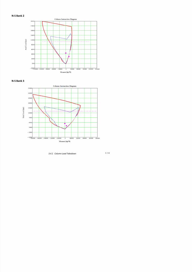
7/17/2019 Structural Design Project of Super Tall Building Chicago Spire
http://slidepdf.com/reader/full/structural-design-project-of-super-tall-building-chicago-spire 279/474
s e . = g
Transor%e Joist $&' + ? 8"8 in#.t 5 't.S = A'SC +esign >uie 11 #"3a
eti4e With ;ator C ? 1 A'SC +esign >uie 11 #"3a
eti4e @anel With ? 8!"0 in 5 C ?(+s.+ ?)1.#
LJ1 = A'SC +esign >uie 11 #"3a
eti4e @anel Weight W ? !,887 lbs 5 /a ?LJ1 = A'SC +esign >uie 11 #"2
sti%ate @ea Aeleration ap.g "8B 5 @oexp("3* n).W ? = A'SC +esign >uie 11 #"1
Joist 2 Details
Joist Length LJ2 212 in
Joist Tributary Area Atr 21,! in2
Steel Size Chosen W12 x 22
Steel Weight 22 pl
Steel Area As !"#8 in2
Steel $o%ent & 'nertia ($&') 'xx 1*! in#
Steel +epth 12"3 in
Joist 2 Calculations
-nior%ly ist loa . length /l ##" lbs.in
-nior%ly ist loa . area /a "#32 lbs.in2
eti4e Conrete With be 8#"8 in 5%in(tributary /ith , "#6L J2)
+istane to entroi ybar "**0 in belo/ top o or% e
Transor%e $&' 't *78 in#
uses parallel axis theore%
$ispan +eletion 9 "!0 in 5 */lLJ2#.38#s't
:atural ;re<ueny n 13"* .s 5 "186s<rt(g.9) = A'SC +esign >uie 11 3"3
Joist Spaing S !"08 t A'SC +esign >uie 11 #"3a
Transor%e Slab $&' +s #"11 in#.t 5 e
3.12n = A'SC +esign >uie 11 #"3a

7/17/2019 Structural Design Project of Super Tall Building Chicago Spire
http://slidepdf.com/reader/full/structural-design-project-of-super-tall-building-chicago-spire 280/474
Transor%e Joist $&' + ? 82"8 in#.t 5 't.S = A'SC +esign >uie 11 #"3a
eti4e With ;ator C ? 1 A'SC +esign >uie 11 #"3a
eti4e @anel With ? 1 in 5 C ?(+s.+ ?)1.#
LJ2 = A'SC +esign >uie 11 #"3a
eti4e @anel Weight W ? 0,1!# lbs 5 /a ?LJ2 = A'SC +esign >uie 11 #"2
sti%ate @ea Aeleration ap.g "32B 5 @oexp("3* n).W ? = A'SC +esign >uie 11 #"1
Joist 3 Details
Joist Length LJ3 2#1 in
Joist Tributary Area Atr 2*,2 in2
Steel Size Chosen W12 x #
Steel Weight # pl
Steel Area As 11"7 in2
Steel $o%ent & 'nertia ($&') 'xx 37 in#
Steel +epth 11"0 in
Joist 3 Calculations
-nior%ly ist loa . length /l #!"! lbs.in
-nior%ly ist loa . area /a "##! lbs.in2
eti4e Conrete With be 0!"# in 5%in(tributary /ith , "#6L J3)
+istane to entroi ybar 1"2*0 in belo/ top o or% e
Transor%e $&' 't 0*2 in#
uses parallel axis theore%
$ispan +eletion 9 "7# in 5 */lLJ3#.38#s't
:atural ;re<ueny n 13" .s 5 "186s<rt(g.9) = A'SC +esign >uie 11 3"3
Joist Spaing S !"08 t A'SC +esign >uie 11 #"3a
Transor%e Slab $&' +s #"11 in#.t 5 e
3.12n = A'SC +esign >uie 11 #"3a
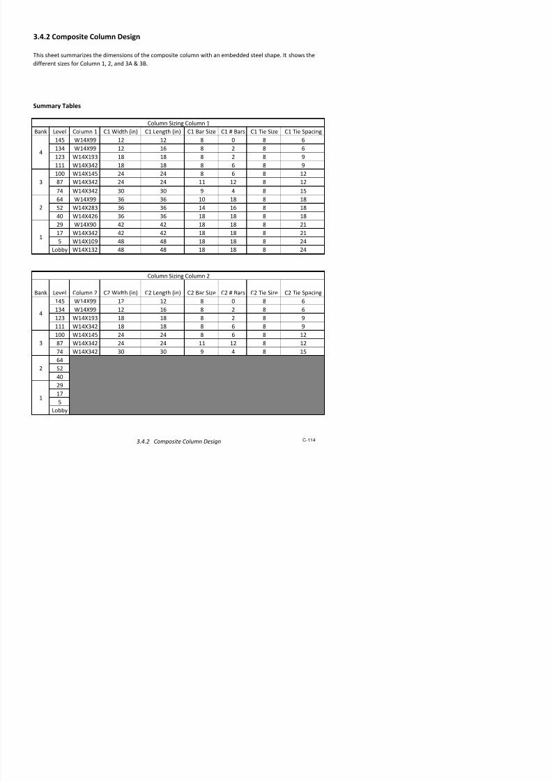
7/17/2019 Structural Design Project of Super Tall Building Chicago Spire
http://slidepdf.com/reader/full/structural-design-project-of-super-tall-building-chicago-spire 281/474
Transor%e Joist $&' + ? 13!"# in#.t 5 't.S = A'SC +esign >uie 11 #"3a
eti4e With ;ator C ? 1 A'SC +esign >uie 11 #"3a
eti4e @anel With ? 1 in 5 C ?(+s.+ ?)1.#
LJ3 = A'SC +esign >uie 11 #"3a
eti4e @anel Weight W ? 1,70 lbs 5 /a ?LJ3 = A'SC +esign >uie 11 #"2
sti%ate @ea Aeleration ap.g "32B 5 @oexp("3* n).W ? = A'SC +esign >uie 11 #"1
Girder Details
Joist Length L> 33* in
Steel Size Chosen W1! x !7
Steel Weight !7 pl
Steel Area As 10"7 in2
Steel $o%ent & 'nertia ($&') 'xx 0*# in#
Steel +epth 1!"3 in
Girder Calculations
-nior%ly ist loa . length /l 80"0 lbs.in
-nior%ly ist loa . area /a "#2# lbs.in2
eti4e Conrete With be 13# in 5%in(tributary /ith , "#6L >)
+istane to entroi ybar 2"3# in belo/ top o or% e
Transor%e $&' 't 2,*#* in#
uses parallel axis theore%
$ispan +eletion 9 "2*# in 5 (#.D)6*/lLJ3#.38#s't
:atural ;re<ueny n 18"3 .s 5 "186s<rt(g.9) = A'SC +esign >uie 11 3"3
A4erage Joist Length L ?a4g 212 t 5 e3.12n = A'SC +esign >uie 11 #"3a
A4erage Joist $&' + ?a4g 81"8 in#.t 5 't.S = A'SC +esign >uie 11 #"3a
Transor%e >irer $&' +g 0"
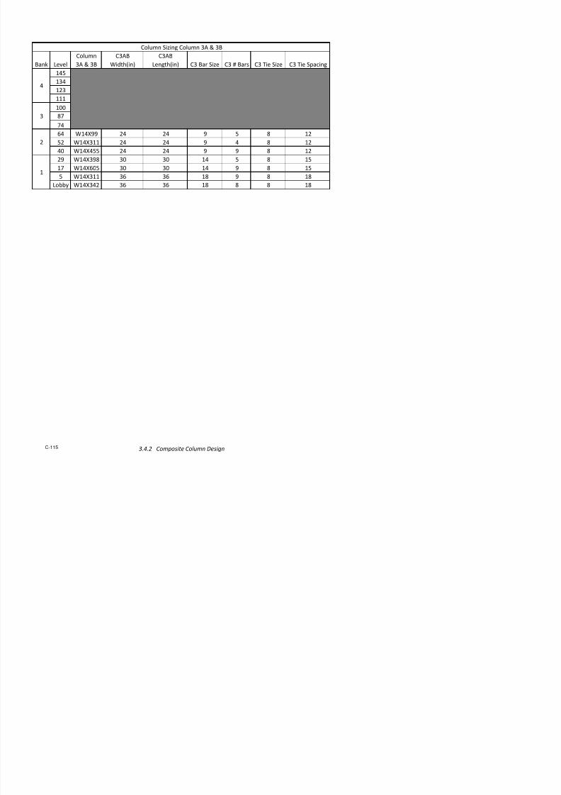
7/17/2019 Structural Design Project of Super Tall Building Chicago Spire
http://slidepdf.com/reader/full/structural-design-project-of-super-tall-building-chicago-spire 282/474
eti4e With ;ator Cg 1"8 A'SC +esign >uie 11 #"3a
eti4e @anel With g 1#1 in 5 C ?(+s.+ ?)1.#
LJ3 = A'SC +esign >uie 11 #"3a
eti4e @anel Weight Wg 2,!0 lbs 5 /a ?LJ3 = A'SC +esign >uie 11 #"2
sti%ate @ea Aeleration ap.g "3B 5 @oexp("3* n).Wg = A'SC +esign >uie 11 #"1
Combined System Calculations
Total Joist +eletion 9 ? "! in a4erage o all ?oist eletions
Total >irer +eletion 9g "2*# in
Total +eletion 9T "31# in
Total :atural ;re<ueny nT !"31 .s 5 "186s<rt(g.9T) = A'SC +esign >uie 11 3"3
Total eti4e Joist Weight W ? 8,0#7 lbs a4erage o all eeti4e ?oist /eights
Total eti4e >irer Weight Wg 2,!0 lbs
Total eti4e Weight WT 17,030 lbs 5 9 ?.(9T)6W ? E 9g.(9T)6Wg = A'SC +esign >uie 11 #"#
sti%ate @ea Aeleration ap.g "100B 5 @oexp("3* nT).W = A'SC +esign >uie 11 #"1
Aeleration Li%it ao.g "*B
Fesap.g G ao.g H

7/17/2019 Structural Design Project of Super Tall Building Chicago Spire
http://slidepdf.com/reader/full/structural-design-project-of-super-tall-building-chicago-spire 283/474
3.!
Coluns 99
3.!.1
Colun Loa& Take&o'n 100
3.!.2
Co$osite Colun Design 11!
3.!.3
Steel Colun Design 11(

7/17/2019 Structural Design Project of Super Tall Building Chicago Spire
http://slidepdf.com/reader/full/structural-design-project-of-super-tall-building-chicago-spire 284/474
3.4.1 Column Load Takedown Created by: CTM 2/15/2012
General Information
Notes:
• The self weight of the columns has not been addressed
• Lie loads were assumed to be non!reducible
• "afety factors of 1#2 for dead loads and 1#$ for lie loads were used
• %an& ' has been diided into 'a and 'b to corres(ond to the two floor (lans receied#
• Column transfers hae been included as necessary and may not a((ear in the sam(le calculations shown#
This series of s(readsheets calculates the graity loads ia tributary areas on the columns and core segments
summing oer the height of the building to determine the a6ial load each column must resist under graity#
• 7ach ban& has the same loads a((lied oer its height so the alues are in(ut at the bottom of the
ban& and refenerenced on the higher leels#• The tributary area and function of each floor are in(ut into the column s(readsheets the s(readsheets
e6(and to allow for multi(le loads ty(es in which case the (ercentage is in(ut to indicate a fraction of the
tributary area for each ty(e#
• %an& transitions hae been shown on ta&edown sheets omitted leels are identical to those immediately
aboe and below#
• )s the core si8e decreases going u( the building the walls are not aligned a6ially causing an eccentricity fromthe from the walls aboe# The core walls segments were chec&ed as columns using an intaction diagram to
identify area where the ececntricity will cause need for e6tra reinforcing#
• The circular core has been modeled as a tra(e8oidal sha(e to be used in the interaction diagram the (lans

7/17/2019 Structural Design Project of Super Tall Building Chicago Spire
http://slidepdf.com/reader/full/structural-design-project-of-super-tall-building-chicago-spire 285/474
Loads
)rea Loads *L "*L LL
+(sf, +(sf, +(sf,
Core 55 5- 100
Lobby+non core, .2 5- 100
(en 0 0 0 slab o(enings
• The circular core has been modeled as a tra(e8oidal sha(e to be used in the interaction diagram the (lans
and dimensions shown corres(ond to these models#
Column Load Summaries
• %an&s . and ' hae 1' e6terior columns columns 1 and 2#
• Column 1 e6tends the full height of the building
• Column 2 e6ists in ban&s . and ' it then s(lits in two columns for ban& 2 and 1 to become .a and .b
set bac& in the column layout +going towards the core, hae not been considered
3inal Loads at 9round Leel
+factored, *L "*L LL
+&i(s, +&i(s, +&i(s,
Column 1 550 -5$' -'1
Column 2 n/a n/a n/a
Column .a '2'2 500 5.-
Column .b '2'2 500 5.-
• The core is diided into four columns of two sha(es a large and small layout on each ban&#
Core Concrete Columns
Exterior Steel Columns
• <n %an&s 1 and 2 the e6terior ring of 21 columns is com(osed of three columns that re(eat seen
times so there are three load scenarios labeled as columns 1 .a and .b#

7/17/2019 Structural Design Project of Super Tall Building Chicago Spire
http://slidepdf.com/reader/full/structural-design-project-of-super-tall-building-chicago-spire 286/474
• %an& ' core geometry has two columns +To( Core, that transfer loads into the four columns of ban& .#
3inal Loads at 9round Leel
+factored, *L "*L LL
+&i(s, +&i(s, +&i(s,
7!; Core -0$ 1.1-1 2'221
!" Core 120$ 1'20. '..50
To( Core n/a n/a n/a
• The layout of four columns is the same for %an&s 1 through . but the dimensions decrease going u(
the building#
Tributary Area Data Created by: CTM/CYW
Color key: User Input
Used in column load takedown
Bank 1 Bank 2
Number of Columns 2 Number of Columns 2
!on" #uter $adius %&'( ft !on" #uter $adius %('% ft
)*ort #uter $adius +,' ft )*ort #uter $adius -%'% ft
.era"e #uter $adius %(' ft .era"e #uter $adius +0', ft
$adius to Column -0'0 ft $adius to Column &+'0 ft
$adius to Core , ft $adius to Core , ft
Column/Core 1oundary $adius 0+' ft Column/Core 1oundary $adius 0,'+ ft
Ma3imum Trib' .rea (-'& ft2
Ma3imum Trib' .rea -%%'+ ft2
Ma3 e3t' len"t* -'2 ft Ma3 e3t' len"t* '& ft
Minimum Trib' .rea &,&'0 ft2
Minimum Trib' .rea 02&'+ ft2
Min e3t' len"t* 2&'& ft Min e3t' len"t* 2,'0 ft
Core Trib .rea 1oundary !ine & , ft Core Trib .rea 1oundary !ine 0+ % ft
Exterior Steel Columns
2//2(2
T*is information was calculated based on t*e preliminary arc*itectural drawin"s usin" .utoC.4'
.ssociated *and calculations are included'

7/17/2019 Structural Design Project of Super Tall Building Chicago Spire
http://slidepdf.com/reader/full/structural-design-project-of-super-tall-building-chicago-spire 287/474
Core Trib' .rea 1oundary !ine &', ft Core Trib' .rea 1oundary !ine 0+'% ft
Bank 3 Bank 4a
Number of Columns , Number of Columns ,!on" #uter $adius +('& ft !on" #uter $adius -2'( ft
)*ort #uter $adius -'+ ft )*ort #uter $adius &', ft
.era"e #uter $adius -&'2 ft .era"e #uter $adius &-'- ft
$adius to Column & ft $adius to Column 0-'-0 ft
$adius to Core 0',2 ft $adius to Core ,' ft
Column/Core 1oundary $adius ,+'2 ft Column/Core 1oundary $adius ,&'( ft2 2
Bank 4b
Number of Columns ,!on" #uter $adius &0' ft
)*ort #uter $adius 0%', ft
.era"e #uter $adius &2', ft
$adius to Column ,%'&20 ft
$adius to Core '& ft
Column/Core 1oundary $adius ,'& ft
Ma3imum Trib' .rea 0-('0 ft2
Ma3 e3t' len"t* 2' ft
Minimum Trib' .rea ,,' ft2
Min e3t' len"t* ft
Core Trib' .rea 1oundary !ine ,,'( ft
centroid distances are alon" t*e a3is of symmetry5 a3is s*ow in dia"ram to ri"*t
Bank 1
Core Concrete Columns

7/17/2019 Structural Design Project of Super Tall Building Chicago Spire
http://slidepdf.com/reader/full/structural-design-project-of-super-tall-building-chicago-spire 288/474
67W Core .rea Centroid
8ft29 8ft9
Column 2+ ,',(0
$esidential Tributary .rea 0-0 7&'&Mec*anical Tributary .rea 2,0 '%
!obby Tributary .rea ,(% '((
N7) Core .rea Centroid
8ft29 8ft9
Column 2 0'00
Bank 2
67W Core .rea Centroid
8ft29 8ft9
Column ,0'++ ',
$esidential Tributary .rea ( 70'+
Mec*anical Tributary .rea 2,0 %
!obby Tributary .rea 0 2
N7) Core .rea Centroid
8ft29 8ft9
Column 2 ,'0-+
$esidential Tributary .rea 0(+ 7,'+0
Mec*anical Tributary .rea ,+ 2',0
!obby Tributary .rea 2, '(0,
#pen to 1elow ,0
Bank 3
67W Core .rea Centroid
8ft29 8ft9
Column &', '
$esidential Tributary .rea +0 70'&

7/17/2019 Structural Design Project of Super Tall Building Chicago Spire
http://slidepdf.com/reader/full/structural-design-project-of-super-tall-building-chicago-spire 289/474
!obby Tributary .rea 222 -
N7) Core .rea Centroid
8ft29 8ft9
Column 2,- ,'&
$esidential Tributary .rea (, 7,'++
Mec*anical Tributary .rea -& %'%0
!obby Tributary .rea -& '
#pen to 1elow &(
Bank 4a
67W Core .rea Centroid
8ft29 8ft9
Column '&&+,
$esidential Tributary .rea %0&'2-0 70'&,
!obby Tributary .rea +%'%& +'0(&
N7) Core .rea Centroid8ft
29 8ft9
Column 2'0
$esidential Tributary .rea -2 70'+%
Mec*anical Tributary .rea 0%( '&
!obby Tributary .rea '0-
Bank 4b
Top Core .rea Centroid
8ft29 8ft9
Column 0- ,'0&,%
$esidential Tributary .rea &- 0'-+-,
Mec*anical Tributary .rea -2+ %'%,-0
!obby Tributary .rea %& 22'(+

7/17/2019 Structural Design Project of Super Tall Building Chicago Spire
http://slidepdf.com/reader/full/structural-design-project-of-super-tall-building-chicago-spire 290/474
Column 1
Bank Level Trib Area DL SDL LL Ext. Lng Load Type DL SDL LL DL SDL LL DL+SDL LL Total DL LL
DL + SDL
ft^2 Use !kips" !kips" !kips" !ft" !kips" !kips" !kips" !kips" !kips" !kips" !kips" !kips" !kips" !kips" !kips"
.
.
.
.
.
.
.
.
.
.
.
.
.
.
.
.
.
.
.
.
.
.
.
.
.
.
.
.
.
.
.
.
.
.
.
.
.
.
.
.
.
.
.
.
.
.
.
.
.
.
.
.
.
.
.
.
.
.
.
.
.
.
.
# $#% &%$ 'e()ani(al $** 22.2 &.% $,.- 2.$ a/ade #.% $*0 2 $% $2- 2% 2$- $% $* $%
# $#, &%$ 'e()ani(al $** 22.2 &.% $,.- 2.$ a/ade #.% $& 2- $% $,$ # 2$- $% $, $%# $#& &%$ 'e()ani(al $** 22.2 &.% $,.- 2 a/ade #.% $,$ # $% $-# #$ 2$- $% $-, $%
# $## &%$ 1esidential $** $0.& $.# $-.# 2.$ a/ade #.% $0& ,, $- 222 %- $ && $- 2&* $-
# $# &%$ 1esidential $** $0.& $.# $-.# 2.$ a/ade #.% 2*0 -% - 2#- $$, ,2 && $- *& -
.
.
.
.
.
.
.
.
.
.
.
.
.
.
.
.
.
.
.
.
.
.
.
.
.
.
.
.
.
.
.
.
.
.
.
.
.
.
.
.
.
.
.
.
.
.
.
.
.
.
.
.
.
.
.
.
.
.
.
.
.
.
.
# $2 &%$ 1esidential $** $0.& $.# $-.# 2.$ a/ade #.% #, ##2 2&2 &&, &$ #* && $- -*& 2&2
# $$ &%$ 1esidential $** $0.& $.# $-.# 2.$ a/ade #.% #0, #%# 2%2 &0 &,0 ## && $- -,* 2%2
# $* &%$ 1esidential $** $0.& $.# $-.# 2 a/ade #.% &*- &*& 2-$ ,$$ ,*, #,, && $- $*$# 2-$
# $2- ,,- 1esidential $** 2$.0 ,.0 22.0 &. a/ade &.$ &,  $# ,## ,&* &*2 ,# 2 $*%0 $#
# $20 ,,- 1esidential $** 2$.0 ,.0 22.0 &. a/ade &.$ &, &%- , ,%, ,-# &0 ,# 2 $$#2 ,
.
.
.
.
.
.
.
.
.
.
.
.
.
.
.
.
.
.
.
.
.
.
.
.
.
.
.
.
.
.
.
.
.
.
.
.
.
.
.
.
.
.
.
.
.
.
.
.
.
.
.
.
.
.
.
.
.
.
.
.
.
.
.
# $$# ,,- 1esidential $** 2$.0 ,.0 22.0 &. a/ade &.$ -- $*-# ,&& $$2% $$ $*#0 ,# 2 2* ,&&
# $$ ,,- 1esidential $** 2$.0 ,.0 22.0 &. a/ade &.$ -,, $$$ ,%0 $$,* $&% $*0& ,# 2 2*-% ,%0
# $$2 ,,- 1esidential $** 2$.0 ,.0 22.0 & a/ade &.$ -- $$,0 %*$ $$-2 $#*$ $$2$ ,# 2 2$,$ %*$
$$$ ,,- Lobby!non (ore" $** 2$.# 0.2 ,,.- & a/ade &.$ $*2* $2*, %,0 $22# $##% $220 ,& ,% 222& %,0
$$* -22 3one *.* *.* *.* a/ade #.0 $*2# $2*, %,0 $22- $##% $220 & * 22* %,0
$*- -22 'e()ani(al $** ,.* -.2 22$.# a/ade #.0 $*,& $2$& -0- $2%0 $#&0 $&02 &* 22$ 220* -0-
$*0 -22 1esidential $** *.* &*.% $.# .$ a/ade #.0 $$** $2,, $*2* $2* $&$- $,2 0, $ 2,, $*2*
$*% -22 1esidential $** *.* &*.% $.# .$ a/ade #.0 $$& $$, $*&2 $,2 $&0* $,0 0, $ 2#&$ $*&2
.
.
.
.
.
.
.
.
.
.
.
.
.
.
.
.
.
.
.
.
.
.
.
.
.
.
.
.
.
.
.
.
.
.
.
.
.
.
.
.
.
.
.
.
.
.
.
.
.
.
.
.
.
.
.
.
.
.
.
.
.
.
.
%% -22 1esidential $** *.* &*.% $.# .$ a/ade #.0 2$%0 200 $--2 2,$# #*, $00 0, $ &*$, $--2
%, -22 1esidential $** *.* &*.% $.# .$ a/ade #.0 22$ 200- 2*2# 2,&, #,% 20 0, $ &$*2 2*2#
%& -22 1esidential $** *.* &*.% $.# a/ade #.0 22#0 2-#* 2*&& 2,-% &20 200 0, $ &$0% 2*&&
2 %# -22 Lobby!non (ore" $** 2-.& &2., -2.2 a/ade #.0 2202 2--2 2$#% 2%0 &-$ #, 0% -2 &2%# 2$#%
2 % 0** 3one $** *.* *.* *.* 2 a/ade #., 220% 2--2 2$#% 2%## &-$ #, & * &2%- 2$#%
2 %2 0** 'e()ani(al $** $.2 0.* $-2.* 2 a/ade #., 222 *** 2- 2%0% ,** %# ## $-2 &2 2-
2 %$ 0** 1esidential $** 2,.* ##.* 2%.2 $., a/ade #., 2& *## 2,% 202# ,& %0, %& 2% &-% 2,%
2 %* 0** 1esidential $** 2,.* ##.* 2%.2 $., a/ade #., 20# *00 2-# 20,* %*, 0* %& 2% &#%2 2-#
.
.
.
.
.
.
.
.
.
.
.
.
.
.
.
.
.
.
.
.
.
.
.
.
.
.
.
.
.
.
.
.
.
.
.
.
.
.
.
.
.
.
.
.
.
.
.
.
.
.
.
.
.
.
.
.
.
.
.
.
.
.
.
2 # 0** 1esidential $** 2,.* ##.* 2%.2 $., a/ade #., 2*- #2%, $20 0&$ &$$ &**& %& 2% %#0& $20
2 #2 0** 1esidential $** 2,.* ##.* 2%.2 $., a/ade #., 2- #2* $&& 00% &$0# &*#0 %& 2% %&&- $&&
2 #$ 0** 1esidential $** 2,.* ##.* 2%.2 2 a/ade #., 2%* #,# $02 -2# &2% &*-2 %& 2% %,# $02
$ #* 0** Lobby!non (ore" $** 2&., #&., 0*.* 2 a/ade #., ** ##$* 2,2 -,* &2-$ &22* %, 0* %%$* 2,2
$ - $*0 3one $** *.* *.* *.* % a/ade &.# *, ##$* 2,2 -,% &2-$ &22* & * %%$& 2,2
$ 0 $*0 'e()ani(al $** #*.& $*.# 2#-.* % a/ade &.# &$ ##2* &$$ #*22 &*# &,$0 &, 2#- %%%$ &$$
$ % $*0 1esidential $** .% &%.$ &. %.2 a/ade &.# -$ ##%% &#% #*,- &%2 &,%& -, & %0,0 &#%
$ , $*0 1esidential $** .% &%.$ &. %.2 a/ade &.# #* #&# &02 #$$, &##$ &%$ -, & %-,# &02
.
.
.
.
.
.
.
.
.
.
.
.
.
.
.
.
.
.
.
.
.
.
.
.
.
.
.
.
.
.
.
.
.
.
.
.
.
.
.
.
.
.
.
.
.
.
.
.
.
.
.
.
.
.
.
.
.
.
.
.
.
.
.
$ % $*0 1esidential $** .% &%.$ &. %.2 a/ade &.# #&,# ,$0- #,*& &#%% %#2% %,0 -, & $*%& #,*&
$ , $*0 1esidential $** .% &%.$ &. %.2 a/ade &.# #,* ,2#, #,#* &&2# %#-& %#2# -, & $*0#- #,#*
$ & $*0 1esidential $** .% &%.$ &. % a/ade &.# #,#2 ,* #,%, &&%$ %&,# %#0$ -, & $*-#, #,%,
$ # %.2 a/ade &.# #,#0 ,* #,%, &&%% %&,# %#0$ & * $*-&$ #,%,
$ %.2 a/ade &.# #,& ,* #,%, &&0# %&,# %#0$ & * $*-&, #,%,
$ 2 %.2 a/ade &.# #,&- ,* #,%, &&-* %&,# %#0$ & * $*-,2 #,%,
$ $ #,&- ,* #,%, &&-* %&,# %#0$ $*-,2 #,%,
4nfa(toreds45 of6 above (ol45n transfer
exterior edge and floor loads
7 total
DL8$.2
7 total
SDL8$.2
7 total
LL8$.,
fro5 trib
s)eet loads taken fro5 s455ary s)eet
DL6 fro5
s455ary s)eet
fro5 trib
s)eet
9ol45n Design'idas:en Loads
4n(tion
Total Loads a(tored LoadsLoa ds ro5 T )i s loor E xt er ior E dge Loa ds
3.4.1 Column Load Takedown C-106

7/17/2019 Structural Design Project of Super Tall Building Chicago Spire
http://slidepdf.com/reader/full/structural-design-project-of-super-tall-building-chicago-spire 291/474
Notes: • Baseline point is the left edge along the axis of symmetry, notated with a zero
• Unless otherwise noted eccentricities are measured from the baseline
• Column transfers are extimated based on geometry, some load is going to walls around elevators, not currently considered
Centroid to Side
used as baseline
Bldg
Center to
Centroid b1 b b! b" h1 h h! h"
#ft$ #ft$ #ft$ #ft$ #ft$ #ft$ #ft$ #ft$ #ft$ #ft$ positive eccentricities %&''
Ban( 1 %&% !)&* 1*&+ 1'&1% 1&'' !*&%* !&%) %&'* 1!&'* 1& eccentricities -1&'1
Ban( "&%* !%&! 1+&+ +&)% 1&'' !*&%* !&)% &% 1"&%* '&%
Ban( ! "&)1 !'&* !&'* "&! '&'' !&+% 1&)+ 1)&)"
Ban( "a &!!1% *&* *&*) "&*+ 1&'' !*&)! & 1&'' %&+' +&) levels where column size will be chec(ed.designed
/et
ec ce n n et f ac to red 0 cc en tr ic it y / et a ct &
Ban( 2evel 3rib 4rea 1 ! " 52 S52 22 52 S52 22 52 S52 22 per level loads per level from centroid 2oads
ft6 Use 7
5ist to
Baseline Use 7
5ist to
Baseline Use 7
5ist to
Baseline Use 7
5ist to
Baseline #(ips$ #(ips$ #(ips$ #(ips$ #(ips$ #(ips$ #(ips$ #(ips$ #(ips$ #(ips$ #(ips$ #(ips$ #(ips$ #ft$ #(ips$ #ft$ #(ips$
&
&
&
&
&
&
&
&
&
&
&
&
&
&
&
&
&
&
&
&
&
&
&
&
&
&
&
&
&
&
&
&
&
&
&
&
&
&
&
&
&
&
&
&
&
&
&
&
&
&
&
&
&
&
&
&
&
&
&
&
&
&
&
&
&
&
&
&
&
&
&
&
&
&
&
&
&
&
&
&
&
&
&
&
&
&
&
&
&
&
&
&
&
&
&
&
"a 11" 1*% 8esidential )&% -%&+ 9echanical !1&% 11&) Core )&' 11&) /one '&' '&' 1* ) !! ' )&!1 )& 1+&*" ,!+ ,!+" *,'11 ,*) ,*! 1,*1* "&*! "*1&"% '&')% 1*,%)
"a 11! 1*% 8esidential )&% -%&+ 9echanical !1&% 11&) Core )&' 11&) /one '&' '&' 1* ) !! ' )&!1 )& 1+&*" ,")" ,"1 *,'" ,+% ,+)% 1!,1 "&*! "*1&"% '&')! 1+,'"+
"a 11 1*% 8esidential )&% -%&*+ 9echanical !1&% 11&)!!! Core ) 11&% /one ' ' 1* ) !! ' )&!1 )& 1+&*" ,%! ,%" *,!+ !,'!* !,'% 1!,"!% "&*! "*1&"% '&') 1+,%!'
! 111 1*% 2obby#non core$ )&% -%&*+ 9echanical !1&% 11&)!!! Core ) 11&% /one ' ' !1! ) !! ' ))& +&1 '&1+ ,%+* ,)) *,)) !,11* !,1% 1!,*)* &)1 )'&!1 1&*' ',1!*
! 11' 1)%! :pen ))&) -"&** 9echanical & +&+% Core "&) *&% :pen )&1 ' ' 1)) ' 1*&* *&'+ +&)) ,)1 ,)!% *,)% !,1"1 !,1)1 1",'" +&* 1**&%" '&'"* ',!)
! 1'+ 1)%! 9echanical ))&) -"&** 9echanical & +&+% Core "&) *&% :pen )&1 ' "* 1)) ' )1&% 1+&1' !)1&* ,)+ ,)%" +,1 !,1% !,1*" 1",)'! -'&+ ))&' -'&1" 1,''
! 1'* 1)%! 8esidential ))&) -"&+ 9echanical & 1'&' Core "&) *&% :pen )&1 '&' 1% 1)) ' %"&)' )*&)" 1!%&'+ ,!" , +,) !,*' !,) 1",*1+ &1 !)"&' -'&'! 1,!))
! 1' 1)%! 8esidential ))&) -"&+ 9echanical & 1'&' Core "&) *&% :pen )&1 '&' 1% 1)) ' %"&)' )*&)" 1!%&'+ ,** ,+1 +,!+ !,!") !,!"+ 1%,'!% &1 !)"&' -'&'! 1,!'
&
& &
&
& &
&
& &
&
& &
&
& &
&
& &
&
& &
&
& &
&
& &
&
& &
&
& &
&
& &
&
& &
&
& &
&
& &
&
& &
&
& &
&
& &
&
& &
&
& &
&
& &
&
& &
&
& &
&
& &
&
& &
&
& &
&
& &
&
& &
&
& &
&
& &
&
& &
&
& &
! 1)%! 8esidential ))&) -"&+ 9echanical & 1'&' Core "&) *&% :pen )&1 '&' 1% 1)) ' %"&)' )*&)" 1!%&'+ ",") ",*%' 1!,"%' %,!11 %,*' 1,%' &1 !)"&' -'&'1 !,)%1
! ) 1)%! 8esidential ))&) -"&+ 9echanical & 1'&' Core "&) *&% :pen )&1 '&' 1% 1)) ' %"&)' )*&)" 1!%&'+ ","*1 ",+1+ 1!,%*% %,! %,+' 1,!) &1 !)"&' -'&'1 !!,'1%
! % 1)%! 8esidential ))&) -"&** 9echanical & +&+% Core "&) *&% :pen )&1 ' 1% 1)) ' %"&)' )*&)" 1!%&'+ ",%!% ",+* 1!,' %,"" %,+*% 1,+% &1 !)"&' -'&'1 !!,!+
" 1)%! 2obby#non core$ ))&) -"&** 9echanical & +&+% Core "&) *&% :pen )&1 ' +" 1)) ' %"&'" '&*" '&% ",%*+ %,'%* 1!,+* %,%' ),'' ,*" '&*% "*&) "&!! !!,*)1
! !1 :pen )%& -"&*% 9echanical 1*&* 1&"% Core 1'&" 1!&'1%" :pen %&) ' ' 1+ 1 ' !'&1* 1*&'% 1*&!) ",)1+ %,') 1",'%) %,%"! ),'+1 ,"+' 1&)' )!&% '&') !",1"
!1 9echanical )%& -"&*% 9echanical 1*&* 1&"% Core 1'&" 1!&'1%" :pen %&) ' )) 1+ 1 ' **&+ !!&1! "+'&1" ",'* %,1'+ 1",%") %,)%' ),1!1 !," '&'+ +!'&" -'&11+ !%,'%%
1 !1 8esidential )%& -"&+ 9echanical 1*&* 1&% Core 1'&" 1!&' :pen %&) '&' "' 1+ 1 ' +&1 1''&+) 1+&)1 ",** %,1' 1",) %,"% ),% !,%)1 "& %'!&%" -'&''" !%,%%+
' !1 8esidential )%& -"&+ 9echanical 1*&* 1&% Core 1'&" 1!&' :pen %&) '&' "' 1+ 1 ' +&1 1''&+) 1+&)1 ",*) %,!11 1",+'% %,*"' ),!! !,*"+ "& %'!&%" -'&''" !),')
&
&
&
&
&
&
&
&
&
&
&
&
&
&
&
&
&
&
&
&
&
&
&
&
&
&
&
&
&
&
&
&
&
&
&
&
&
&
&
&
&
&
&
&
&
&
&
&
&
&
&
&
&
&
&
&
&
&
&
&
&
&
&
&
&
&
&
&
&
&
&
&
&
&
&
&
&
&
&
&
&
&
&
&
&
&
&
&
&
&
&
&
&
&
&
&
"! !1 8esidential )%& -"&+ 9echanical 1*&* 1&% Core 1'&" 1!&' :pen %&) '&' "' 1+ 1 ' +&1 1''&+) 1+&)1 ,''" *,'! 1+,%% *,"'% +,)"% !1,)'* "& %'!&%" -'&''! "+,)%*
" !1 8esidential )%& -"&+ 9echanical 1*&* 1&% Core 1'&" 1!&' :pen %&) '&' "' 1+ 1 ' +&1 1''&+) 1+&)1 ,'*! *,1!* 1+,+!% *,%'' +,)) !1,*+% "& %'!&%" -'&''! %',1)1
"1 !1 8esidential )%& -"&*% 9echanical 1*&* 1&"% Core 1'&" 1!&'1%" :pen %&) ' "' 1+ 1 ' +&1 1''&+) 1+&)1 ,1)! *,!+ ',11" *,%+% +,** !,1*! "& %'!&%" -'&''! %',))%
1 "' !1 2obby#non core$ )%& -"&*% 9echanical 1*&* 1&"% Core 1'&" 1!&'1%" :pen %&) ' "' 1+ 1 ' *&"1 1'!&+* +&1' ,"1 *,!"! ',!+! *,)*+ 1','1 !,)+ &'% ))%&"! 1&") %1,!!'
1 !+ !)) :pen )! -%&)! 9echanical 1* 1"&+% Core 1!& 1!&+) :pen %&* ' ' 1*+ + ' !!&+ &') 1!!&"" ,% *,!)% ',% *,!' 1','!* !,*"! 1"&)! *'&% '&'%' %1,)11
1 !* !)) 9echanical )! -%&)! 9echanical 1* 1"&+% Core 1!& 1!&+) :pen %&* ' ))' 1*+ + ' +1&+ !)&+ "+1&1* ,!) *,"' 1,'1* *,*"' 1','* !!,)+ '&"1 +"'&%% -'&'+1 %,%%1
1 ! !)) 8esidential )!&' -%&) 9echanical 1*&' 1%&' Core 1!& 1"&' :pen %&* '&' !* 1*+ + ' *&! 1'"&'" 1*"&1 ,""+ *,%') 1,' *,+!+ 1',' !!,+! %&!" %1*&1 -'&'' %!,')+
1 !) !)) 8esidential )!&' -%&) 9echanical 1*&' 1%&' Core 1!& 1"&' :pen %&* '&' !* 1*+ + ' *&! 1'"&'" 1*"&1 ,%!1 *,)1' 1,!*) +,'! 1',!! !",1* %&!" %1*&1 -'&'' %!,%*
&
&
&
&
&
&
&
&
&
&
&
&
&
&
&
&
&
&
&
&
&
&
&
&
&
&
&
&
&
&
&
&
&
&
&
&
&
&
&
&
&
&
&
&
&
&
&
&
&
&
&
&
&
&
&
&
&
&
&
&
&
&
&
&
&
&
&
&
&
&
&
&
&
&
&
&
&
&
&
&
&
&
&
&
&
&
&
&
&
&
&
&
&
&
&
&
1 !)) 8esidential )!&' -%&) 9echanical 1*&' 1%&' Core 1!& 1"&' :pen %&* '&' !* 1*+ + ' *&! 1'"&'" 1*"&1 +,+1) 11,) ),) 11,*++ 1!,+%! ",)1 %&!" %1*&1 -'&''1 )*,)1!
1 ) !)) 8esidential )!&' -%&) 9echanical 1*&' 1%&' Core 1!& 1"&' :pen %&* '&' !* 1*+ + ' *&! 1'"&'" 1*"&1 +,++* 11,!1 ),+1' 11,++* 1",'* "!,'%) %&!" %1*&1 -'&''1 )+,1!11 % !)) 8esidential )! -%&)! 9echanical 1* 1"&+% Core 1!& 1!&+) :pen %&* ' !* 1*+ + ' *&! 1'"&'" 1*"&1 1','*' 11,*!% ,'+" 1,'+) 1",'! "!,!%' %&!" %1*&1 -'&''1 )+,)"+
1 " 1','*' 11,*!% ,'+" 1,'+) 1",'! "!,!%' )+,)"+
1 ! 1','*' 11,*!% ,'+" 1,'+) 1",'! "!,!%' )+,)"+
1 1','*' 11,*!% ,'+" 1,'+) 1",'! "!,!%' )+,)"+
1 1 1','*' 11,*!% ,'+" 1,'+) 1",'! "!,!%' )+,)"+
actored 2oads
2oads rom 3his loor
#Unfactored$
N-S Core
3otal 2oads By unction, actored 3otal 2oads
unction 1 unction unction ! unction "
3.4.1 Column Load TakedownC-107

7/17/2019 Structural Design Project of Super Tall Building Chicago Spire
http://slidepdf.com/reader/full/structural-design-project-of-super-tall-building-chicago-spire 292/474
Core Columns to Evaluate Created by: CTM
• These are the levels where we are going to check the columns on the interaction diagram
• We are considering each bank to be one column since it is all the same shape
E-W Core
Eccentricity Load
(t! (kips!
"ank # "ottom $%$$$ &'$)
Top #%*#$ +$*##
"ank * "ottom ,$%$#- *.-'
Top -%)- #-)#)
"ank + "ottom $%$&' #-&+'
Top $%)+& .$.
"ank &a "ottom ,$%#)- -'-)
Top %$+# **#'
N-S Core
Eccentricity Load
• We selected the bottom o each bank where the loads are largest and the top where the eccentricity is
greatest to plot on the interaction diagrams% This gives two points per core section per bank that need to
be plotted%

7/17/2019 Structural Design Project of Super Tall Building Chicago Spire
http://slidepdf.com/reader/full/structural-design-project-of-super-tall-building-chicago-spire 293/474
y
(t! (kips!
"ank # "ottom $%$$$ ..&
Top #%&*. -#++$
"ank * "ottom ,$%$$+ -$..-Top &%+'+ ++).#
"ank + "ottom ,$%$*# +++'
Top #%)'$ *$#+)
"ank &a "ottom $%$.* #-+$
Top &%)+. ##+&.
Column Interaction Diagrams for Core Segments Under Gravity
E-W Bank 1
These diagrams show where the initial wall size estimates need to be increased and reinforced to
address the moments resulting from the eccentricity of the core walls above each bank. The core was
evaluated with little to no rebar to understand the response of the concrete. Lateral loads have no
yet been addressed the sizes will need to be adjusted further after these loads are considered.

7/17/2019 Structural Design Project of Super Tall Building Chicago Spire
http://slidepdf.com/reader/full/structural-design-project-of-super-tall-building-chicago-spire 294/474
E-W Bank 2
E-W Bank

7/17/2019 Structural Design Project of Super Tall Building Chicago Spire
http://slidepdf.com/reader/full/structural-design-project-of-super-tall-building-chicago-spire 295/474
E-W Bank !a
"-S Bank 1

7/17/2019 Structural Design Project of Super Tall Building Chicago Spire
http://slidepdf.com/reader/full/structural-design-project-of-super-tall-building-chicago-spire 296/474
"-S Bank 2
"-S Bank

7/17/2019 Structural Design Project of Super Tall Building Chicago Spire
http://slidepdf.com/reader/full/structural-design-project-of-super-tall-building-chicago-spire 297/474
"-S Bank !a

7/17/2019 Structural Design Project of Super Tall Building Chicago Spire
http://slidepdf.com/reader/full/structural-design-project-of-super-tall-building-chicago-spire 298/474
3.4.2 Composite Column Design
Summary Tables
Bank Level Column 1 C1 Width (in) C1 Length (in) C1 Bar Size C1 # Bars C1 Tie Size C1 Tie Spacing
14 W14!"" 1 1 $ % $ &
1'4 W14!"" 1 1& $ $ &
1' W14!1"' 1$ 1$ $ $ "
111 W14!'4 1$ 1$ $ & $ "
1%% W14!14 4 4 $ & $ 1
$ W14!'4 4 4 11 1 $ 1
4 W14!'4 '% '% " 4 $ 1
&4 W14!"" '& '& 1% 1$ $ 1$
W14!$' '& '& 14 1& $ 1$
4% W14!4& '& '& 1$ 1$ $ 1$
" W14!"% 4 4 1$ 1$ $ 1
1 W14!'4 4 4 1$ 1$ $ 1 W14!1%" 4$ 4$ 1$ 1$ $ 4
Lo* W14!1' 4$ 4$ 1$ 1$ $ 4
This sheet summarizes the dimensions o+ the composite column ,ith an emedded steel shape- .t sho,s the
di++erent sizes +or Column 1/ / and '0 'B-
1
4
'
Column Sizing Column 1

7/17/2019 Structural Design Project of Super Tall Building Chicago Spire
http://slidepdf.com/reader/full/structural-design-project-of-super-tall-building-chicago-spire 299/474
Bank Level Column C Width (in) C Length (in) C Bar Size C # Bars C Tie Size C Tie Spacing14 W14!"" 1 1 $ % $ &
1'4 W14!"" 1 1& $ $ &
1' W14!1"' 1$ 1$ $ $ "
111 W14!'4 1$ 1$ $ & $ "
1%% W14!14 4 4 $ & $ 1
$ W14!'4 4 4 11 1 $ 1
4 W14!'4 '% '% " 4 $ 1
Column Sizing Column
4
'
Bank Level
Column
'0 'B
C'0B
Width(in)
C'0B
Length(in) C' Bar Size C' # Bars C' Tie Size C' Tie Spacing
14
1'4
1'
111
1%%$
4
&4 W14!"" 4 4 " $ 1
W14!'11 4 4 " 4 $ 1
4% W14!4 4 4 " " $ 1
" W14!'"$ '% '% 14 $ 1
1 W14!&% '% '% 14 " $ 1
W14!'11 '& '& 1$ " $ 1$
Lo* W14!'4 '& '& 1$ $ $ 1$
Column Sizing Column '0 'B
1
4
'

7/17/2019 Structural Design Project of Super Tall Building Chicago Spire
http://slidepdf.com/reader/full/structural-design-project-of-super-tall-building-chicago-spire 300/474
Composite Column Design Created by: DF/JL 12/9/2011
2 Color Key: User Input
Floor 40 Constant/Prevous Cal!"
1 Cal!/Loo#up
$es Passes C%e!#Overall Checks &o Fals C%e!#
L'tatons Pass( $)*
+,al Capa!ty Pass( $)*
92"9-
Loading Sheet
14.41 #ps29 #ps
1 #ps
#ps
193 #ps
otal Fa!tored Load Pu 1.4 #ps
Detailing Requirements
3 n +I*C I2516
4 n +I*C I2516
1 n +I*C I2516
1 n +I*C I2516
%s spreads%eet !al!ulates t%e !o'pressve !apa!ty o6 a 75s%ape e'bedded n !on!rete usn8 +I*C
C%apter I2
=an#
7e8%t o6 *teel above 2
7e8%t o6 Con!rete above 2
7e8%t o6 *teel bet@een 2540
Lo!aton
Colu'n
- Capa!ty Used
Fa!tored rbutary Loads
7e8%t o6 Con!rete bet@een 2540
1<en6or!n8 Da'eter
4e Da'eter
0"An D'enson
e *pa!n8

7/17/2019 Structural Design Project of Super Tall Building Chicago Spire
http://slidepdf.com/reader/full/structural-design-project-of-super-tall-building-chicago-spire 301/474
1 n +I*C I2516
Inputs
*teel *e!ton
Colu'n 7dt% b 3 n
Colu'n Len8t% L! 3 n
)66e!tve Len8t% Fa!tor K 1
Unbra!ed e8%t o6 Colu'n 1 n
Con!rete Co'p" *tren8t% 6! 14 #s
Con!rete Densty ; 10 lbs/6t3
An'u' *%ear *tud *pa!n8
714B42
e +rea +tr 0"31 n2
e =ar Da'eter dte 0"2 n*%ear *tud *pa!n8 s 1 n
Cover ! 1" n
Limitations
*teel at least 1-( $)* +I*C I251a
An'u' ransverse ren6or!e'ent o#( $)* +I*C I251a
<en6or!e'ent rato o#( $)* +I*C I251a
Parameters
+rea o6 *teel *e!ton +s 12 n2
+rea o6 <ebar +sr 2 n2
+barnbar
+rea o6 es +tr n2
+tr ntes
Eross +rea +8 1.29 n2
bL!
+rea o6 Con!rete +! 1.099 n2
+8 5 +s
Aodulus o6 )last!ty Con!rete )! .3 #s ;!1"
6!0"
Aodulus o6 )last!ty *teel )s 29.000 #s
An" $eld *tress *teel *e!ton Fy 0 #s
An" $eld *tress =ars Fyr 0 #s
Inerta o6 *teel *e!ton Is 1.110 n4
Inerta o6 *teel =ars Isr 1.03 n4
2nbar dbar4/4 G +bard
2
Inerta o6 Con!rete I! 121.23 n4
bL!3/12 5 Is 5 Isr
C1 0"3 0"1 G 2H+s/ H+! G +s 0"3 +I*C I25
)66e!tve *t66ness )I )G0 #p5n ) I G 0 ) I G C ) I +I*C I25

7/17/2019 Structural Design Project of Super Tall Building Chicago Spire
http://slidepdf.com/reader/full/structural-design-project-of-super-tall-building-chicago-spire 302/474
)66e!tve *t66ness )Ie66 ")G0 #p n )sIs G 0" )s Isr G C1 )C IC +I*C I25
Compressive Strength
+,al *tren8t% o6 *teel *e!ton Ps .20 #ps +sFy
+,al *tren8t% o6 *teel <ebar Psr 4.320 #ps +srFyr
+,al *tren8t% o6 Con!rete P! 13.0 #ps 0" 6! +!
+,al Co'pressve *tren8t% Po 23.4 #ps Ps G Psr G P! +I*C I254
)66e!tve Co'pressve *tren8t% Pe 219.99 #ps 2)Ie66 /HK
2 +I*C I25
&o'nal Co'pressve *tren8t% Pn 22.0 #ps PH0"HPo/Pe
+I*C I252

7/17/2019 Structural Design Project of Super Tall Building Chicago Spire
http://slidepdf.com/reader/full/structural-design-project-of-super-tall-building-chicago-spire 303/474
Load Capacity5llo>able )uas( )tress ,Fy 4 ks#
last#$ Cr#t#$al Bu$kl#n* )tress Fe 1 k#ps 3-4
last#$ Bu$kl#n* &#%#t Fl#% 113 417/Fy81/2
a#%u% 5#al &oad !%a 124 k#ps ? F$r@5
+edu$t#on Fa$tor , 09
Fa$tored a 5#al &oad ,!%a 114 k#ps
C(e$k: ,!%a !uD 'es
I. &e.. E Fl#% use 3-2 else
use 3-3ks#43F$rFleural Bu$kl#n* )tress

7/17/2019 Structural Design Project of Super Tall Building Chicago Spire
http://slidepdf.com/reader/full/structural-design-project-of-super-tall-building-chicago-spire 304/474
4.0 Lateral Design
4.1 Building as a Cantilever 121
4.2 MIDAS Gen FEA Summary 124
4. !reliminary C"re #all $%i&'ness Cal&ulati"n ( )" *utriggers 12+
4.4
Final C"re #all $%i&'ness Cal&ulati"n ( *utriggers 12,
4.+ C"re -ear Design 11
4.+.1 Design "/ C"re -ear /"r erti&al and "ri"ntal S%ear 12
4.+.2 Design "/ C"re -ear /"r Fle3ural Caa&ity 14
4.+. Mat%&ad /"r Ban' 4 Str"ng A3is Bending 1,
4.5 Energy Met%"d *timiati"n 1+5
4.5.1 *timiati"n Cal&ulati"ns 1+,
4.5.2
-esiing "/ Built(6 Memers 151

7/17/2019 Structural Design Project of Super Tall Building Chicago Spire
http://slidepdf.com/reader/full/structural-design-project-of-super-tall-building-chicago-spire 305/474
4.1 Preliminary Deflection Calculations Created by: CYW 5/11/2012
Bank:
Location:
Bank 1 Properties
Wall thickness tc 7 ftCenterline radius R c 40 ft
Centerline circuference Cc 251 ft ! 2"#"$c
%uter radius R o 4&'5 ft ! $c(tc/2
)nner radius R i &*'5 ft ! $c+tc/2
,oent of inertia -100. solid all Ic 141203 ft4
! #/4"-$o2+$i
2
%enin lenth in core/a Log 15 ft
6uber of as Ng 4
otal oen lenth in core Lo *0 ft = Log*Ng
8ercentae of solid all Ps 7*. ! 100. + Lo/Cc
ransfored oent of inertia -ith oenins It 1073*&7 ft4 = Ic*Ps
Bank 1 heiht h 51&'5 ft
Concrete strenth f9c 14000 si
Concrete odulus conc *744&&1 si ! 57000"f9c1/2
; <C) &1+0 '5
otal Bank 1 ind load fro $W=) wtotal 210 kis
=istributed ind load w 4'1 kis/ft ! total/h
Bank 2 Properties
1 to 4
Core
>enerate sectional roerties of the core all for a sile cantile?er deflection check in ,<@<6'

7/17/2019 Structural Design Project of Super Tall Building Chicago Spire
http://slidepdf.com/reader/full/structural-design-project-of-super-tall-building-chicago-spire 306/474
Wall thickness tc 4 ft
Centerline radius R c &3 ft
Centerline circuference Cc 245 ft ! 2"#"$c
%uter radius R o 41'0 ft ! $c(tc/2
)nner radius R i &7'0 ft ! $c+tc/2
,oent of inertia -100. solid all Ic 747&5 ft4
! #/4"-$o2+$i
2
%enin lenth in core/a Log 15 ft
6uber of as Ng 4
otal oen lenth in core Lo *0 ft = Log*Ng
Bank 3 Properties
Wall thickness tc & ft
Centerline radius R c & ft
Centerline circuference Cc 2&3 ft ! 2"#"$c
%uter radius R o &3'5 ft ! $c(tc/2
)nner radius R i &*'5 ft ! $c+tc/2
,oent of inertia -100. solid all Ic 5173*2 ft4
! #/4"-$o2+$i
2
%enin lenth in core/a Log 15 ft
6uber of as Ng 4
otal oen lenth in core Lo *0 ft = Log*Ng
8ercentae of solid all Ps 75. ! 100. + Lo/Cc
ransfored oent of inertia -ith oenins It &700 ft4 = Ic*Ps
Bank & heiht h 47 ft
Concrete strenth f9c 14000 si
Concrete odulus conc *744&&1 si ! 57000"f9c1/2
; <C) &1+0 '5
otal Bank & ind load fro $W=) wtotal 2544 kis
=istributed ind load w 5'2 kis/ft ! total/h
Bank 4 Properties
Wall thickness tc 2 ft
Centerline radius R c &4 ftCenterline circuference Cc 210 ft ! 2"#"$c
%uter radius R o &4'5 ft ! $c(tc/2
)nner radius R i &2'5 ft ! $c+tc/2
,oent of inertia -100. solid all Ic 2&* 423 ft4
! #/4"-$o2+$i
2

7/17/2019 Structural Design Project of Super Tall Building Chicago Spire
http://slidepdf.com/reader/full/structural-design-project-of-super-tall-building-chicago-spire 307/474
,oent of inertia -100. solid all Ic 2&*423 #/4 -$o $i
%enin lenth in core/a Log 15 ft
6uber of as Ng 2
otal oen lenth in core Lo &0 ft = Log*Ng
8ercentae of solid all Ps *. ! 100. + Lo/Cc
ransfored oent of inertia -ith oenins It 2027&2 ft4 = Ic*Ps
Bank 4 heiht h 44 ft
Concrete strenth f9c 14000 si
Concrete odulus conc *744&&1 si ! 57000"f9c1/2
; <C) &1+0 '5
t l B k 4 i d l d f $W=) 2 &34 ki
MASTAN utput

7/17/2019 Structural Design Project of Super Tall Building Chicago Spire
http://slidepdf.com/reader/full/structural-design-project-of-super-tall-building-chicago-spire 308/474
!n"eforme" Deforme"
4.2 MIDAS Gen FEA Summary Created by: CYW 5/11/2012
Modeling Approach Loading Conditions
• Outriggers are modeled as truss elements.
• All lateral forces are alied along t!e "#a$is at
eac! floor.
• %nfactored dead loads and li&e loads from t!e
column load ta'edo(n (ere alied to nodes at
column ends.
• )!e total unfactored dead load and li&e load for
t!e core (as slit e*ually into nodal forces to t!e
nodes connecting t!e radial girders to t!e core (alls
or lin' beams.
• All belt trusses and outriggers are modeled (it!
in#in end#releases.
• All ot!er structural elements !a&e been alied
fi$ed#fi$ed end#releases.
• Core (alls are modeled as t!ic' late element (it!
drilling +O,.
• -#bracing belt trusses bet(een an' 1 and an' 2
are modeled as beam elements.
A detailed t!ree dimensional structural analysis of t!e ire (as conducted using +A en. All material
roerties and baseline element s!aes (ere ta'en from initial lateral and gra&ity design. 3ertical members4
outriggers and belt trusses4 and core (all t!ic'nesses (ere resi"ed t!roug!out t!e iterati&e modeling rocess
based on element forces and moments4 and ser&iceability re*uirements.
• )!e model sans from t!e lobby at ground
ele&ation to t!e to of le&el 1.• )!e mega#columns and core (all at t!e ground
ele&ation are fi$ed to t!e ground.
• )!e (ind data from (ind tunnel testing is used
directly for strengt! design.• )!e (ind data from (ind tunnel testing is reduced
by a factor of 0.67 for ser&iceability design.
• All ot!er belt trusses are modeled as truss
elements.
• Comosite floor beams are modeled as W#!ae
teel =einforced Concrete >=C? in cross sectionroerties. )!e (idt! c!osen in t!ese =C beams
are based on t!e effecti&e (idt! of t!e comosite
beam from t!e gra&ity design.
• +A en calculates material self#(eig!t in t!e
analysis4 t!us no self#(eig!t is considered in alied
dead loads.
• 2 load combinations are used for ser&iceability
design c!ec's.
• 5 load combinations are used for strengt! designc!ec's.
• Cantile&ers and angled floor girders outside of t!e
e$terior column grid are not modeled.

7/17/2019 Structural Design Project of Super Tall Building Chicago Spire
http://slidepdf.com/reader/full/structural-design-project-of-super-tall-building-chicago-spire 309/474
• 8yot!etical tuned mass damer and mec!anical
floors at t!e ire9s ea' are not modeled.
• Concrete strengt! of fc ; 14000 si is used in all&ertical concrete elements.
• Concrete strengt! of fc ; 4000 si is used in all
!ori"ontal concrete elements.
• A) A<<2 standard (it! ,y ; 504000 si steel is
used.
g
t r i g g e r s
C r e a t e d b y : C J B & A D V
1 / 2 0 / 2 0 1 2
C O L O R S
K ! "
U s e r I n p u t
C o n s t a n t / % r e $ o
u s C a ' c (
, 0 0 0 ! c 3 4 A C I - 1 5 5 (
( 1
C a ' c / 6 o o # u p
8 e s
% a s s e s C h e c #
; o
9 a $ ' s C h e c #
(
4 a
4 )
; o t e s
, "
1 1 1
1 - 0
- 2
2
2
t
"
-
2
t
- +
2 5
2 ,
t
. < $
? t
5
0 0
- 2 ,
t 2
. < o 2
< $ 2
3
" @ +
1 5
1 , @
"
1 1 0
@ ,
t "
. / " 3
< o
"
< $
3
" 1 , -
" "
1 2 2
, 5
+ " +
@ 2
t -
. E o ' o o r s 3 A c
h
- - -
+ +
1 -
+
+ 5
1 0
# $ p
- , 0
, +
2 1 2
- 5
1 - "
@ +
# $ p
@ , 1
, 0
- 0 -
@
1 0 -
1
# $ p
. 7 c
G C o n c r e t e V o ' u e A b o e 3
" 2 0 0
0 0
, 0 0
0 0
1 2 0 0
0 0
# $ p t
U n a c t o r e d o e n t s 9 r o F $ n d = u n n e ' 6 o
a d s $ n F $ n d 6 o a d s ( ' s
5 @ ,
+ ,
5 0 2 2
, +
2 2 -
" 5
# $ p t
U n a c t o r e d o e n t s r o S e $ s $ c o r c e s $ n
S e $ s $ c 6 o a d s ( ' s
(
4 a
4 )
- (
2
2 ( 0
+ +
1 ( 0
0
# s $
2 ( +
@ 5
1 ( "
+ -
0 ( "
+
# s $
. 0 (
! c 4 A C I - 1 5 1 " ( ( 2
. , (
! c 3
( 4 A C I - 1 5 @ ( ( 2 ( -
) o d u ' u s o <
u p t u r e
= h e s e a r e
t h e a a ' u e s r o t h e ' o a d c o
b $ n a t $ o n s b e ' o H (
K r e e n :
a ' u e $ s ' e
s s t h a n a ' ' o H a b ' e
( < e d : a ' u e $ s g r
e a t e r t h a n a ' ' o H a b ' e
(
C o r e H a ' '
d e s $ g n e d o r c r $ t $ c a ' s t r e s s e s a t t h e b a s e o t h e ' $ s t e d ' o o r $ ( e (
s t r e s s e s r o ' o o r " 0 d $ c t a t e c o r e H a ' ' d e s $ g n o r ' o o r s " 0 , - 3
U n a c t o r e d ' o a d s c a ' c u ' a t e d r o c u u ' a t $
e o r c e s o n c o r e H a ' '
s e c t $ o n s
o u n d $ n L C o ' u n 6 o a d = a # e d o H n ( ' s L
e r a ' s e $ s $ c a n d H $ n d
o r c e s t o c a ' c u ' a t e t h e r e M u $ r e d c o r e t h $ c # n e s s ( = h e c a ' c u ' a t $ o
n s a r e o n ' y b a s e d o n t h e
e e t h e s $ s t e r s h e e t t o t h $ s o n e
L C o r e F a ' ' C a ' c u ' a t $ o n
> u t r $ g g e r s L ( = h e u s e r c a n c h a n g e t h e c o r e p r o p e r t $ e s
2
P r e l i m i n a r y C o r e W
a l l T h i c k n e s s C a l c u l a t i o n - N o O u t r i g g e r s

7/17/2019 Structural Design Project of Super Tall Building Chicago Spire
http://slidepdf.com/reader/full/structural-design-project-of-super-tall-building-chicago-spire 310/474
T h i c k n e s s C a l c u l a t i o n - N o O u t
i e s ! c
1 "
# s $
* c
+ , " " - - 1
# s $
.
7 c
1 + 0
p c
h
1 - ( 2
t
& l o o r
'
2
1
" 0
< $
- "
- "
t
5
+
< o
" 2
" 0
A c
1 @ 1 0
1 - @
I c
1 -
@ " -
+ "
@ + 1 0 + -
"
V c
@ 5 - -
1 -
+ 2 + 0 1 +
"
% e r & l o o r
D 6
5 1 @
5
+ 0
2 "
6 6
5 " "
+ "
@ @
0 5
F c
- " +
+ -
1 @ , - - -
) H
@ "
1 0 0
0 0
1 + 0
0 0 0
2
) s
5 5
2 1 +
+ ,
" 5
1 "
2
# , l l o a ) l e S t r e s s e s
'
2
C a p p
+ ( "
+ 5
" ( + " ,
= a p p
- ( +
1 0
2 ( @
5 @
c o p
. / (
# s $
r
- 0 . 1 1
# s $
a $ t y ' o a d s a n d o e n t s $ n d u
c e d b y ' a t e
g e r s a r e n o t $ n c ' u d e d
( 9 o r o u t
r $ g g e r s s e
o n + o t h e A S C * , ' o a d c o b
$ n a t $ o n s ( 4
.
, "
1 1 1
1 - 0
1 5 2 ,
1
+ " 0
2
2 " 0
2
# $ p
. 1 ( "
D
6 ? F c 3 4
A S C * , 0 2 ( - ( 2
1 ( "
5
0 ( 5
@ 0
0 (
1 1
# s $
. 9 D 6 A
c
, "
1 1 1
1 - 0
1 + +
" -
" @
0 1
2 0
@ -
# $ p
. 1 ( 2
D
6 ? F c 3 4
A S C * , 0 2 ( - ( 2
@ -
2 2
- - @
5 1
2 1
@ "
# $ p
. 1 ( +
6 6
4 A S C * , 0 2 ( - ( 2
1 ( ,
1 ( 2
- +
0 ( 5
@ ,
# s $
. 9 D 6 ?
9 6 6 3 / A
c
, "
1 1 1
1 - 0
1 + +
" -
" @
0 1
2 0
@ -
# $ p
. 1 ( 2
D
6 ? F c 3 4
A S C * , 0 2 ( - ( 2
- 5
, 2 0
0 0
@ 1 2 0
0 0
1 @ 2 0
0 0
# $ p t
. 1 ( +
)
H 4 A S C * , 0 2 ( - ( 2
- , 0
, +
2 1 2
- 5
1 - "
@ +
# $ p
. 1 ( 2
6 6 4 A S C * , 0 2 ( - ( 2
1 (
, "
1 ( 0
@
0 ( ,
2
# s $
. 9 D 6 ?
9 6 6 3 / A
c
1 ( @
-
1 ( 0
0 5
0 ( -
2 +
# s $
. 9 ) H
<
o / I c
1 ( @
-
1 ( 0
0 5
0 ( -
2 +
# s $
. b
- (
2 ,
2 ( 0
+ +
1 ( 0
0
# s $
. a ? b
0 ( -
, @
; / A
; / A
# s $
. a
? t
, "
1 1 1
1 - 0
1 + +
" -
" @
0 1
2 0
@ -
# $ p
. 1 ( 2
D
6 ? F c 3 4
A S C * , 0 2 ( - ( 2
2 5
@ ,
+ ,
5 0 2 2
, +
2 2 -
" 5
# $ p t
. 1 ( 0
)
s 3 4 A S C * , 0 2 ( - ( 2
- , 0
, +
2 1 2
- 5
1 - "
@ +
# $ p
. 1 ( 0
6
6 3 4 A S C * , 0 2 ( - ( 2
0 ( ,
0 "
0 ( 2
, ,
0 ( 1
2 "
# s $
. 9 D 6 ?
9 6 6 3 / A
c
1 ( "
" -
0 ( 5
5 ,
0 ( -
5 2
# s $
. 9 ) s < o
/ I c
1 ( "
" -
0 ( 5
5 ,
0 ( -
5 2
# s $
. b
2 ( 1
" ,
1 ( 1
+ -
0 (
0 +
# s $
. a ? b
0 ( ,
- 5
0 ( +
1 0
0 ( 2
5
# s $
. a
? t
) a n k o 6 t h e S % i r e 7 u s i n g , S C - 0 5 L o a #
. 2
P r e l i m i n a r y C o r e W
a l l T h i c k n e s s C a l c u l a t i o n - N o O u t r i g g e r s

7/17/2019 Structural Design Project of Super Tall Building Chicago Spire
http://slidepdf.com/reader/full/structural-design-project-of-super-tall-building-chicago-spire 311/474
1
" 0
9 D 6
+ 1 1 2
+ @
- " , 0 0
N c
2 ( 2
2 2
1 ( , + +
L
1
" 0
9 D 6
2 - @
"
- 0 " 0 2 5
9 6 6
1 - 1
" 2
@ 5
-
N c
2 ( -
@ +
1 ( @ @ 1
W
L
1
" 0
9 D 6
2 - @
"
- 0 " 0 2 5
9 )
H
1 0
+ 0
0 0
5 2 +
0 0 0
-
6 6
5 " "
+ "
@ @
0 5
a
2 ( 2
1 2
1 ( 5 1 2
b
- ( 1
" @
2 ( - 5 +
t
- ( 1
" @
2 ( -
5 +
N c
( -
+ 1
" ( 1 @ 5
N t
0 ( @
- ,
0 (
, "
0 L
1
" 0
9 D 6
2 - @
"
- 0 " 0 2 5
9 )
s
5 5
2 1 +
+ ,
" 5
1 "
2
9 6 6
5 " "
+ "
@ @
0 5
a
2 ( 2
1 2
1 ( - 2 -
b
1 ( 5
"
1 ( 5
t
1 ( 5
"
1 (
5
N c
" ( 0
,
2 ( @ 0 @
N t
; / A
0 ( 2
+ 2
# N e t T e n s i o n S t r e s s e s a t t h e ) a
s e o 6 e a c h
( . 2
9 "
4
, "
1 1 1
1 - 0
1 1 , "
5 -
" 1 1
, +
1 "
"
# $ p
. 0 ( @
D
6 ? F c 3 4
A S C * , 0 2 ( - ( 2
+ 1
@ 2
0 0
1 "
@ 2 0
0
- 0 , 2
0 0
# $ p t
. 1 ( +
)
H 4 A S C * , 0 2 ( - ( 2
0 ( "
2 ,
0 ( 1
0
0 ( 0
+
# s $
. 9 D 6 ?
9 6 6 3 / A
c
- ( 1
2
1 ( +
1 -
0 (
2 1
# s $
. 9 ) H
<
o / I c
- ( 1
2
1 ( +
1 -
0 (
2 1
# s $
. b
- (
2
1 ( ,
+ 2
0 (
, ,
# s $
. a ? b
2 ( +
@ 5
1 ( "
+ -
0 ( "
+
# s $
. a
? t
, "
1 1 1
1 - 0
1 1 , "
5 -
" 1 1
, +
1 "
"
# $ p
. 0 ( @
D
6 ? F c 3 4
A S C * , 0 2 ( - ( 2
2 5
@ ,
+ ,
5 0 2 2
, +
2 2 -
" 5
# $ p t
. 1 ( 0
)
s 3 4 A S C * , 0 2 ( - ( 2
0 ( "
2 ,
0 ( 1
0
0 ( 0
+
# s $
. 9 D 6 ?
9 6 6 3 / A
c
1 ( "
" -
0 ( 5
5 ,
0 ( -
5 2
# s $
. 9 ) s < o
/ I c
1 ( "
" -
0 ( 5
5 ,
0 ( -
5 2
# s $
. b
1 ( 5
, 0
1 ( 0
- +
0 ( "
- 5
# s $
. a ? b
1 ( 0
1
0 ( ,
- ,
0 ( -
2 +
# s $
. a
? t
4 . 2
P r e l i m i n a r y C o r e W
a l l T h i c k n e s s C a l c u l a t i o n - N o O u t r i g g e r s

7/17/2019 Structural Design Project of Super Tall Building Chicago Spire
http://slidepdf.com/reader/full/structural-design-project-of-super-tall-building-chicago-spire 312/474
W
1
" 0
9 D 6
- @ 2 @
@
2 2 5 0 2 1
9 )
H
2 " 0
5 @ +
0 0
1 - 2 0
@ +
0 0
+
a
1 ( "
2 @
0 ( 5 2 @
b
( 0
- @
- ( 5 1 5
t
( 0
- @
- ( 5
1 5
N c
+ ( "
+ 5
" ( + " ,
N t
- ( +
1 0
2 ( @
5 @
0
1
" 0
9 D 6
- @ 2 @
@
2 2 5 0 2 1
9 )
s
5 5
2 1 +
+ ,
" 5
1 "
2
a
1 ( "
2 @
0 ( 5 2 @
b
1 ( 5
"
1 ( 5
t
1 ( 5
"
1 (
5
N c
- ( 2
, "
2 ( " 1 "
N t
0 ( "
1 ,
0 ( ,
+
4
C r
e a t e d b y : A D V
1 / 2 5 / 2 0 1 2
C O L O R S K E
Y :
U s e r I n p u t
C o n s t a n t / # r e $ " o u s C a % c &
0 0 - . f ' c A C I + 1 & 5 & 1
C a % c / 3 o o ! u p
e
s
# a s s e s C h e c !
8 o
6 a " % s C h e c !
3
a
!
8 o t e s
*
1 1 1
1 + 0
+ 2
2 5
2 5
f t
+
2
f t
+ )
2
2 *
f t
, 9 " < t
5 5
5 0 0
+ 2 *
f t > 2
, ? - 9 o
2 7 9 " 2
= 5 ) 1
1 * 5 = 5
1 1 0 5 = *
f t >
, ? / - 9 o
7
9 "
5 5 *
1 2 * 2 1
0 5 0
f t >
6 r o @ B C o % u @
n S y s t e @ # r o p e r t " e s & % s B
0 & *
0 & *
0 & *
2 0 +
1 5
1 1 + + 2
f t >
I t o t a % , I c o r e <
o
- I c o % u @ n s
1 * +
1 2 5 2 *
) ) = 2
f t > +
, E o f f % o o r
s - A c
- h
+ + ) )
1 5 + 5 )
) 1 0
! " p
* 0 * )
2 1 2 +
1 + = )
! " p
* 1 * 0
+ 0 + = 5
1 0 + 5 1
! " p
, 4 c
- G C o n
c r e t e V o % u @ e A b o $ e
2 0 0 0 0
5 * 0 0 0 0
1 2 0 0 0 0
! " p 7 f t
U n f a c t o r e d @ o @ e n t s 6 r o @ F " n d u n n e % 3 o a d s " n
F " n d 3 o a d s & % s
5 = * ) *
0 2 2 * )
2 2 5 +
! " p 7 f t
U n f a c t o r e d @ o @ e n t s f r o @ S e " s @ " c f o r c e s " n S e " s @
" c 3 o a d s & % s
s @ " c a n d H " n d f o r c e s t o c a % c u % a t e t h e r e u " r e d c o r e t h " c ! n e s s & h e c a % c u % a t " o n s a r e o n % y b a s e d
o n t h e c o r e f o r % a t e r a %
h " s o n e
B C o r e F a % % C a % c u % a t " o n 7 ; u t r " g g e r s B & h e u s e r c a n c
h a n g e t h e c o r e p r o p e r t " e s t o d e s " g
n f o r t h e @ o @ e n t s
C o r e H a % % d e
s " g n e d f o r c r " t " c a % s t r e s s e s a t t h e b a s e
o f t h e % " s t e d f % o o r " & e &
s t r e s s e s f r o @
f % o o r 0 d " c t a t e c o r e H a % % d e s " g n f o r
f % o o r s 0 7 * +
U n f a c t o r e d % o a d s c a % c u % a t e d f r o @ c u @ u % a t " $ e f o r c e s o n c o r e H a % % s e c t " o n s
f o u n d " n B C o
% u @ n 3 o a d a ! e d o H n &
% s B
4 . 3
F i n a l C o r e W
a l l T h i c k n e s s C a l c u l a t i o n - O u t r i g g
e r s

7/17/2019 Structural Design Project of Super Tall Building Chicago Spire
http://slidepdf.com/reader/full/structural-design-project-of-super-tall-building-chicago-spire 313/474
f ' c
1
! s "
( c
) * + + 1
! s "
, 5 * 0
4 c
1 ) 0
p c f
h
1 + & 2
f t
r B a n k p e r F l o o r
1
2 0
9 "
+
+
t
)
9 o
2
0
A c
1 = 1 0
1 + = 5
I c
1 + = + )
= ) 1 0 ) +
=
I o
5 + * +
1 = * 0 0 1
+ 5
o
0 & *
0 & *
I t
1 * * 1 2 = 5
1 0 = = )
5 2
V c
= + + 1 +
) 2 ) 0 1 )
1
F l o o r
D 3
1 = 5
5 ) 0 2
+ +
3 3
)
5 = = 0
+ *
F c
+ 5 ) ) +
1 = * + + +
= *
H
= 1 0 0 0 0
5 1 ) 0 0 0 0
2
s
2 1 ) ) *
5 5 1 5
2
C a l c u l a t i o n ( O u t r i g g e r s
% o a d s a n d @ o @ e n t s " n d u c e d b y
% a t e r a % s e "
d & 6 o r o u t r " g g e r s s e e t h e s " s t e r s h e e t t o t h
a t " o n s &
3
a
!
+ & +
2 & 0 1
1 & 0 2
! s "
2 & 5 =
7 1 & + 5
7 0 & 5 2
! s "
+ K
2 K
1 K
) K
5 K
+ K
, 0 & 5 5 - - f ' c A C I + 1 1 & 5 & 2
, * & 5
- f ' c >
& 5 A C I + 1 = & 5 & 2 & + o d u % u s o f 9 u p t u r e
*
1 1 1
1 + 0
2 * 5
) 0 5 2
2 0 2 5
! " p
, 1 &
- D 3 < F c A S C ( * 7 0 5 2 & + & 2
1 & 5
0 & = 0
0 & 5 1 1
! s "
, 6 D 3 / A c
*
1 1 1
1 + 0
5 ) ) +
5 = 0
2 0 5 = +
! " p
, 1 & 2
- D 3 < F c A S C ( * 7 0 5 2 & + & 2
5 = + 2 2
+ + =
2 1 5 =
! " p
, 1 & )
- 3 3 A S C ( * 7 0 5 2 & + & 2
1 & * 5 5
1 & 2 + )
0 & = *
! s "
, 6 D 3 < 6 3
3 / A c
*
1 1 1
1 + 0
5 ) ) +
5 = 0
2 0 5 = +
! " p
, 1 & 2
- D 3 <
F c A S C ( * 7 0 5 2 & + & 2
* 2 0 0 0
= 1 2 0 0 0
1 = 2 0 0 0
! " p 7 f t
, 1 & )
- H
A S C ( * 7 0 5 2 & + & 2
+ * 0 * )
2 1 2 +
1 + = )
! " p
, 1 & 2
- 3 3 A
S C ( * 7 0 5 2 & + & 2
1 & 5 *
1 & 0 5 =
0 & * 2 5
! s "
, 6 D 3 < 6 3
3 / A c
1 & ) 0
0 & = 5 =
0 & + 1 *
! s "
, 6 H
- 9 o / I c
1 & ) 0
7 0 & = 5 =
7 0 & + 1 *
! s "
, 7 f b
+ & +
2 & 0 1
1 & 0 2
! s "
, f a < f b
0 & 2 )
8 / A
8 / A
! s "
, f a < f t
h e s e a r e t h
e p e r c e n t r e d u c t " o n s " n a " @ u @ A p p % " e d S t r e s s e s H h e n
" n c % u d " n g t h e o u t r " g g e r s
' ! a n k o 4 t ' e S p i r e 6 u s i n g
* S C E ( 1 / L o a d
h e s e a r e t h
e @ a $ a % u e s f r o @ t h e % o a d c o @ b " n a t " o n s b e % o H & M r e e n : $ a % u e " s
% e s s t h a n a % % o H a b % e & 9 e d : $ a % u e " s g r e a t e r t h a n a % % o
H a b % e &
4 . 3
F i n a l C o r e W
a l l T h i c k n e s s C a l c u l a t i o n - O u t r i g g
e r s

7/17/2019 Structural Design Project of Super Tall Building Chicago Spire
http://slidepdf.com/reader/full/structural-design-project-of-super-tall-building-chicago-spire 314/474
l l o + a ! l e S t r e s s e s
1
2
C a p p
5 & + = 5
& 1 )
+
a p p
7 2 & 5 +
7 2 & 5 1 0
7
1 * K
1 0 K
+ 0 K
1 ) K
f c o m p
- $ . 3
! s "
f r
( / $ 0 0
! s "
0
6 D 3
) 1 1 2 ) =
+ 5 * 0 0
1
L c
2 & 2 2 2
1 & * ) )
1
0
6 D 3
5 2 + = 5
+ 0 0 2
1 5
6 3 3
1 + 5 1 2
= 5 5 +
5
L c
2 & + = )
1 & = = 1
1
L
0
6 D 3
5 2 + = 5
+ 0 0 2
1 5
6 H
1 5 0 5 ) 0 0 0
2 5 ) 0 0
0
+
3 3
)
5 = = 0
+
f a
2 & 2 1 2
1 & 1 2
1
f b
2 & * =
2 & 0 *
1
f t
7 2 & * =
7 2 & 0 *
7
L c
& ) = 1
+ & = =
+
L t
7 0 & 2 ) *
7 0 & 2 * 5
7
5 e t & e n s i o n S t r e s s e s a t t ' e ! a s
e o 4 e a c '
$ 2 8 :
*
1 1 1
1 + 0
5 ) ) +
5 = 0
2 0 5 = +
! " p
, 1 & 2
- D 3 <
F c A S C ( * 7 0 5 2 & + & 2
5 = * ) *
0 2 2 * )
2 2 5 +
! " p 7 f t
, 1 & 0
- s
A S C ( * 7 0 5 2 & + & 2
5 = + 2 2
+ + =
2 1 5 =
! " p
, 1 & 0
- 3 3
A S C ( * 7 0 5 2 & + & 2
0 & * 5
0 & + 2 +
0 & 1 5 +
! s "
, 6 D 3 < 6 3
3 / A c
1 & + *
0 &
0 & + * 2
! s "
, 6 s - 9 o / I c
7 1 & + *
7 0 &
7 0 & + * 2
! s "
, 7 f b
2 & 1 5 =
1 & 1 ) *
0 & 5 2 )
! s "
, f a < f b
7 0 & 5 =
7 0 & 5 2 1
7 0 & 2 1 =
! s "
, f a < f t
*
1 1 1
1 + 0
1 * +
1 1 * )
1 5 5
! " p
, 0 & =
- D 3 <
F c A S C ( * 7 0 5 2 & + & 2
1 = 5 2 0 0
1 5 = 2 0 0
+ 0 * 2 0 0
! " p 7 f t
, 1 & )
- H
A S C ( * 7 0 5 2 & + & 2
0 & 2 *
0 & 1 5 0
0 & 0 5 )
! s "
, 6 D 3 < 6 3
3 / A c
2 & = * )
1 & 5 + 5
0 & 5 0
! s "
, 6 H
- 9 o / I c
7 2 & = * )
7 1 & 5 + 5
7 0 & 5 0
! s "
, 7 f b
+ & 0 +
1 & ) 5
0 & 5 )
! s "
, f a < f b
7 2 & 5 =
7 1 & + 5
7 0 & 5 2
! s "
, f a < f t
*
1 1 1
1 + 0
1 * +
1 1 * )
1 5 5
! " p
, 0 & =
- D 3 <
F c A S C ( * 7 0 5 2 & + & 2
5 = * ) *
0 2 2 * )
2 2 5 +
! " p 7 f t
, 1 & 0
- s
A S C ( * 7 0 5 2 & + & 2
0 & 2 *
0 & 1 5 0
0 & 0 5 )
! s "
, 6 D 3 < 6 3
3 / A c
1 & + *
0 &
0 & + * 2
! s "
, 6 s - 9 o / I c
7 1 & + *
7 0 &
7 0 & + * 2
! s "
, 7 f b
1 & 0 1
0 & = =
0 & 2 =
! s "
, f a < f b
7 0 & = *
7 0 & ) =
7 0 & + 1 )
! s "
, f a < f t
4 . 3
F i n a l C o r e W
a l l T h i c k n e s s C a l c u l a t i o n - O u t r i g g
e r s

7/17/2019 Structural Design Project of Super Tall Building Chicago Spire
http://slidepdf.com/reader/full/structural-design-project-of-super-tall-building-chicago-spire 315/474
L
0
6 D 3
5 2 + = 5
+ 0 0 2
1
6 s
2 1 ) ) *
5 5 1 5
2
6 3 3
1 + 5 1 2
= 5 5 +
5
f a
2 & + = )
1 & 5
f b
1 & 5 +
1 & + )
f t
7 1 & 5 +
7 1 & + )
7
L c
+ & =
2 & 0
L t
8 / A
8 / A
7
0
6 D 3
+ = 2 = 5 =
2 2 0 2
1
6 H
2 0 = ) 0 0
1 + 2 0 = ) 0 0
)
f a
1 & 2 =
0 & 2 =
f b
+ & = ) *
+ & + + =
f t
7 + & = ) *
7 + & + + =
7
L c
5 & + = 5
& 1 )
L t
7 2 & 5 +
7 2 & 5 1 0
7
0
6 D 3
+ = 2 = 5 =
2 2 0 2
1
6 s
2 1 ) ) *
5 5 1 5
2
f a
1 & 2 =
0 & 2 =
f b
1 & 5 +
1 & + )
f t
7 1 & 5 +
7 1 & + )
7
L c
2 & 1
2 & 2 1 5
L t
7 0 & 0 2
7 0 & 5 5 *
7
s i g n
r e i n f o r c i n g b a r s w e r e s u
f f i c i e n t f o r f l e x u r e a s w e l l .
o r i z o n t a l S h e a r
V e r t i c a l S h e a r
F l e x u r a l
a r S i z e
S p a c i n g
B a r S i z e
S p a c i n g
i n
i n
1 !
"
1 #
1 $ a s v e r t i c a l s h e a r
1 !
"
1 #
1 $ a s v e r t i c a l s h e a r
1 !
!
1 !
' a s v e r t i c a l s h e a r
1 !
'
1 !
1 # a s v e r t i c a l s h e a r
1 )
1 #
!
1 " a s v e r t i c a l s h e a r
1 )
'
*
1 $ a s v e r t i c a l s h e a r
1 !
*
"
1 ) a s v e r t i c a l s h e a r
!
1 *
"
1 ) a s v e r t i c a l s h e a r
o t e + i n a
l l
c a s e s , v e r
t i c a l
s h e a r r e b a r w a s
g n e f o r t h e s h e a r i n i t - s p a r t i c u l a r i r e c t i o n t h e o r t h
/ S o u t h 0 o r e S e c t i o n s a r e
o r t h / S o u t h i r e c t i o n , e t c .
c o r e s w o r k i n p a i r s t o r e s i s t o e n t . 2 h e o r t h / S o u t h
c o r e s w o r k t o g e t h e r t o
e x / a x i s , w h i l e t h e % a s t / &
e s t c o r e s w o r k t o g e t h e r t o r e s i s t o e n t a b o u t t h e 3 /
e r e a r e o n l 3 t w o c o r e s ,
o r t h a n S o u t h . 2 h e 3 w o r k t o
g e t h e r t o r e s i s t t h e
s , b u t h a v e t o w o r k i n i v i u a l l 3 t o r e s i s t t h e o e n t a
b o u t t h e 3 / a x i s .
5
4 . 5
C o r e R e b a r D e s i g n
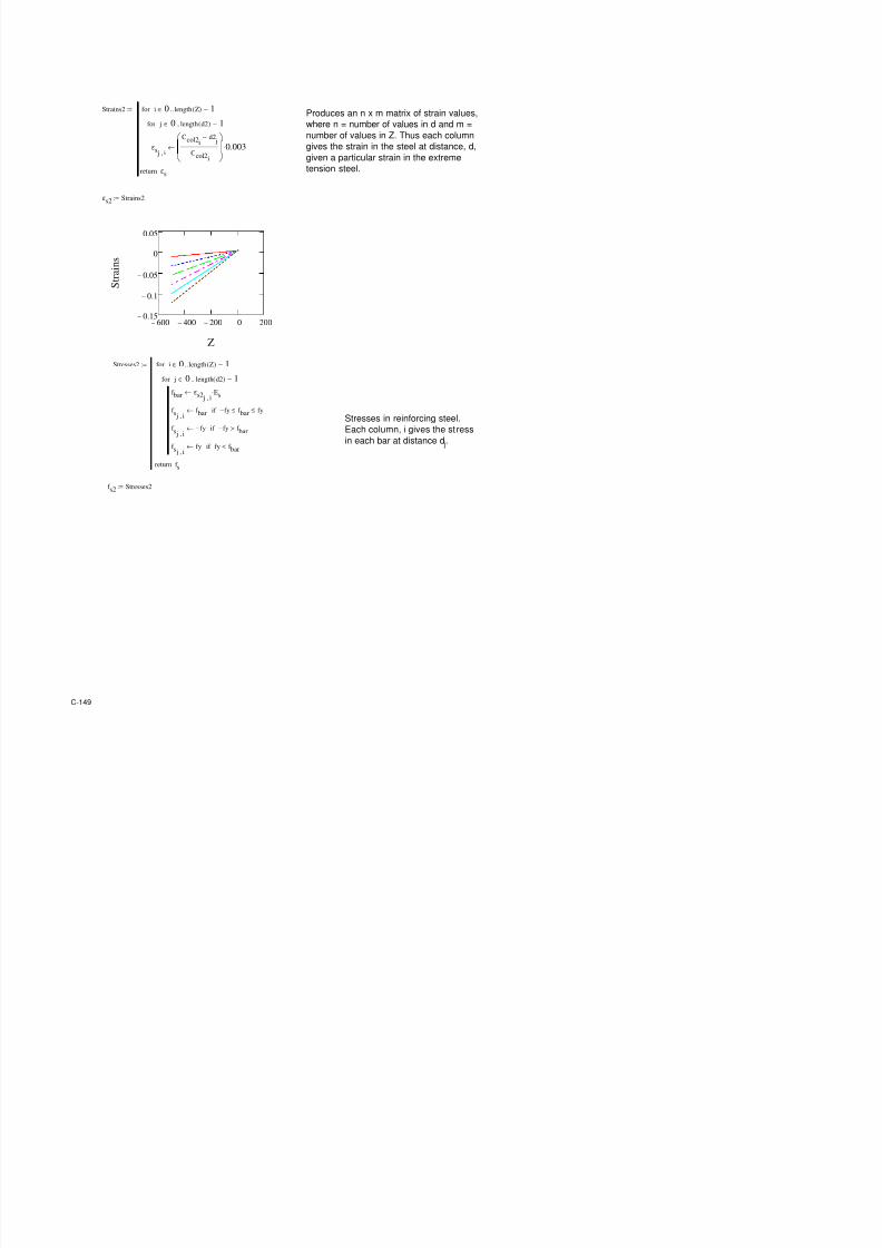
7/17/2019 Structural Design Project of Super Tall Building Chicago Spire
http://slidepdf.com/reader/full/structural-design-project-of-super-tall-building-chicago-spire 316/474
4 . 5 C o r e R e b a r D e s
N o t e s
I n a l l c a s e s , t h e v
e r t i c a l r
R e b a r S u m m a r y
H B
B a n k 1
S
% &
B a n k $
S
% &
B a n k (
S
% &
B a n k )
) . 1 ) . $
% a c h c o r e s e c t i o n i s e s i g
e s i g n f o r s h e a r i n t h e
I n B a n k s 1 , $ , a n ( , t h e
r e s i s t o e n t a b o u t t h e
a x i s . 4 n t h e ) t h B a n k , t h
o e n t a b o u t t h e x / a x i s
C-131
4.5.1 Design of Core Rebar for Vertical and Horizontal Shear
Created by: KMC 5/9/2012
Inputs
Max Horizontal Shear Vu,hor 23,99 !i"#
Max Verti$al Shear Vu, %er 0 !i"#
&xial 'or$e (u 3),521 !i"#
Co*"re##i%e Stren+th o Con$rete -$ 1.,000 "#i
all hi$!ne## h ). in
all en+th l 503 in
all Hei+ht h ,12 in
&""roxi*ate Stru$tural e"th d .02 in 4 0)l6 119.
Mai!u! "er!itted Concrete Shear Strength
7 085 1193
Max Shear Stren+th 7V 299). !i"# 4 710#rt- ;hd6 11 9 3
y"i$al $al$ulation #hon or ?an!1, @orthASouth Core Se$tion
he or* o the hand $al$ a# ta!en ro* (C& @ote# on &CB 31)A0), "a+e 21A28 throu+h
21A296 all reeren$e# are to &CB 31)A0)
S"read#heet ta!e# the load# #hear and axial; ro* MB&S, and, u#in+ the #ize# o MB&S- re"re#entation
o the $ore, $al$ulate# the reuired rebar to re#i#t horizontal #hear
here i# no %erti$al #hear, #o the %erti$al reinor$in+ i# deter*ined "urely ro* the $ode re+ulation# he
#hear# $ho#en are the or#t $a#e, a# are the axial load#

7/17/2019 Structural Design Project of Super Tall Building Chicago Spire
http://slidepdf.com/reader/full/structural-design-project-of-super-tall-building-chicago-spire 317/474
Max Shear Stren+th 7Vn 299). !i"# 4 710#rt $;hd6 1193
7Vn o!ay< 7Vn=Vu, hor< >e#
Shear Strength "ro#ided b$ Concrete
l/2 251 inh/2 3,0)1 in
(o#ition o $riti$al #hear y 251 in 4 *inl/2, h/2;6 1198
Mo*ent at Criti$al Se$tio Mu 1.1,)30,85) !i"#Ain 4 Vu, hor;h A y;
Shear Stren+th (ro%ided b V$ 2,).3 !i"# D#ee belo
Horizontal Shear Reinforce!ent
Horizontal #hear de#i+ned in a$$ordan$e ith 1199
>ield Stren+th o Steel 'y 0 !#i
Steel &rea/S"a$in+ Eatio &%/# 121 in2/in 4 Vu, hor A 7V$;/7'yd;6 e 11A29
?ar Size F 1)
&rea o Cho#en ?ar Size &bar .00 in2
Max S"a$in+ #*ax 2 in 4 *inl/5, 3h, 1);6 11993
Sele$ted S"a$in+ ##ele$ted in
Gro## &rea &+ 50. in 4 hD##ele$ted
Eatio o Steel to Con$rete #teel 0015)8 4 2D&%/&+
#"a$in+ #*all enou+h< ##ele$tedI#*ax< >e#
enou+h rebar< #teelI00025< >e# 11992

7/17/2019 Structural Design Project of Super Tall Building Chicago Spire
http://slidepdf.com/reader/full/structural-design-project-of-super-tall-building-chicago-spire 318/474
Vertical Shear Reinforce!ent
?ar Size F 10
&rea o Cho#en ?ar Size &bar 128 in2
Max S"a$in+ #*ax 1)00 in 4 *inl/3, 3h, 1);6 11995
Sele$ted S"a$in+ ##ele$ted 12 in
4*in00025, 00025 J 05D25 A
h/l;tran# A 00025;;6 e 11A30Eeuired Min #teel *in 000250
4.5.2 Design of Core Rebar for Flexural CapacityCreated by: KMC 5/9/2012
Inputs
h1 19.6 in
h2 80.3 in
h3 102 in
h4 102 in
b1 241 in
b2 65.4 in
b3 12 in
b4 372 in
Distance fr! center f cre t far ed"e f cre d 527 in
C#er c 2 in
$ie%d &tren"th f &tee% 'y 60 (si
C!)ressi#e &tren"th f Cncrete f*c 14000 )si
Desi"n M!ent M+ 45055 ft,(i)s
-his s)readsheet ta(es a "i#en cnfi"+ratin f rebar di!ensins f the cre !ateria% )r)ertiesre+ired !!ent ca)acity and deter!ines hether ca)acity f c%+!n is ade+ate. t des s by
ca%c+%atin" !!ent ca)acity f c%+!n ass+!in" a%% tensin stee% has yie%ded and far ed"e f cncrete
has crac(ed.

7/17/2019 Structural Design Project of Super Tall Building Chicago Spire
http://slidepdf.com/reader/full/structural-design-project-of-super-tall-building-chicago-spire 319/474
1 5
3 4
2
Concrete Equivalent Area Calculations
Calculations
c
art in3
1 641 h1b2/2 514 d,2/3h 329674
2 641 h1b2/2 514 d,2/3h 329674
3 4732 h1b1 517 d,h1/2 2447372
4 29843 h2b4 467 d,h1,h2/ 13944127
5 1213 h3b3 376 d,h1,h2, 456064
6 1213 h3b3 376 d,h1,h2, 456064
&+! 38284 17962974
cn 469 in cr/c
Di!ensions of equivalent pris!atic s"apeen"th % 116 in d,cn2
;idth b 331 in c/%
#train Calculations
c rea
-he cre is an irre"+%ar sha)e that is diffic+%t t r( ith !athe!atica%%y. -h+s a%% f the si@ )arts f the creshn n )re#i+s )a"e*s drain" i%% be added t"ether and then transfr!ed int an e+i#a%ent rectan"+%ar
sha)e. -his rectan"+%ar sha)e i%% ha#e the sa!e area f the cre the sa!e and its far ed"e i%% be in the
sa!e )sitin as the far ed"e f the ri"ina% cre s that e@tre!e cncrete c!)ressin fiber i%% be in the
sa!e )%ace.
in2
in

7/17/2019 Structural Design Project of Super Tall Building Chicago Spire
http://slidepdf.com/reader/full/structural-design-project-of-super-tall-building-chicago-spire 320/474
#train Calculations
< strain in tensin stee% and cncrete is %isted and strain in c!)ressin stee% is ca%c+%ated.
Dist t <ear =d"e f -en &tee% fr! Center dists 427 in d,h4 > c
&train in -ensin &tee% ?s 0.00207
Dist t 'ar =d"e f Cncrete fr! Center distc 527 in d
&train in 'ar =d"e f Cncrete ?c 0 003
#teel Equivalent Area Calculations
in in A in2
in2
in3
2 525 10 1.27 21 26.7 14002
14 513 10 1.27 27 34.3 17591
26 501 10 1.27 31 39.4 19724
38 489 10 1.27 31 39.4 19252
50 477 10 1.27 31 39.4 18779
62 465 10 1.27 31 39.4 18307
74 453 10 1.27 31 39.4 17835
86 441 10 1.27 31 39.4 1736298 429 10 1.27 2 2.54 1090
110 417 10 1.27 2 2.54 1059
122 405 10 1.27 2 2.54 1029
134 393 10 1.27 2 2.54 998
146 381 10 1 27 2 2 54 968
&i!i%ar t cncrete it is diffic+%t t dea% ith each indi#id+a% bar f rebar. -h+s the each cre*s rebar i%% be
transfr!ed int an e+i#a%ent area f stee% ith the sa!e as the ri"ina% %ay+t f stee% in the sa!e ay
that the cncrete as transfr!ed.
Dist fr! 'ar
=d"e f
Cncrete
d , dist
fr! far ed"e
f cncrete barBar &ie
<+!ber
f Bars
s -ta%
rea f
&tee% s
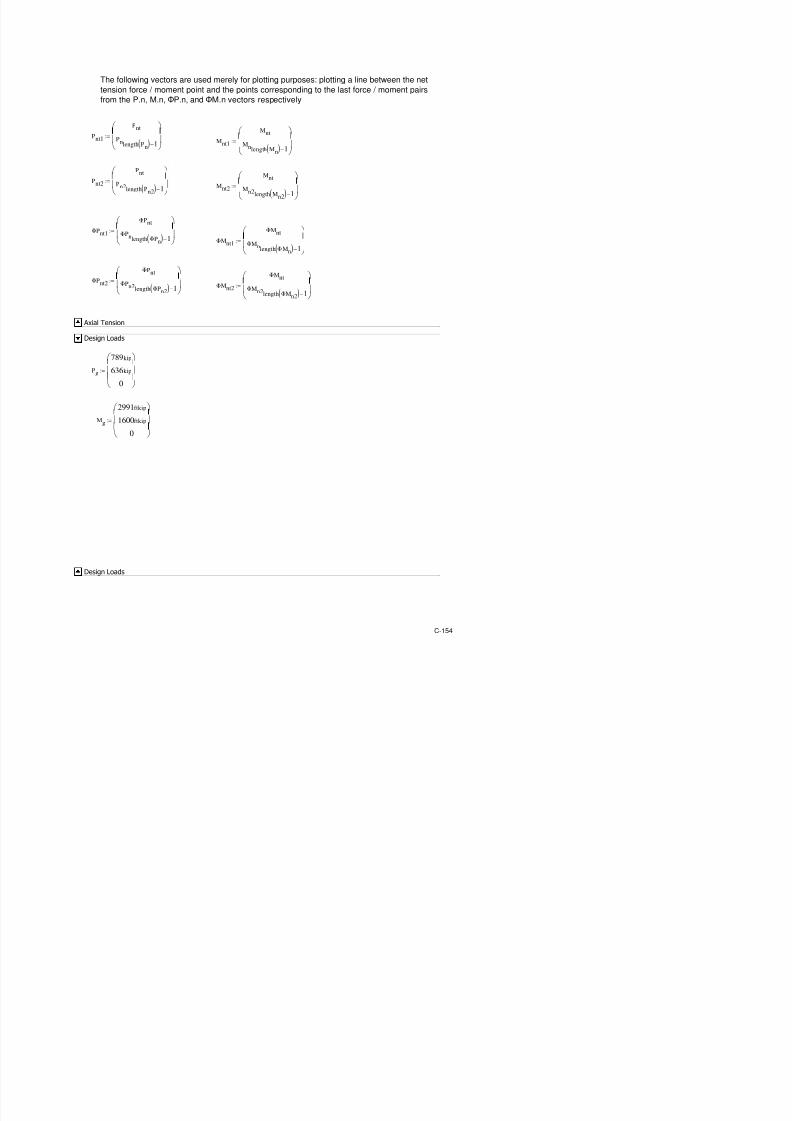
7/17/2019 Structural Design Project of Super Tall Building Chicago Spire
http://slidepdf.com/reader/full/structural-design-project-of-super-tall-building-chicago-spire 321/474
146 381 10 1.27 2 2.54 968
158 369 10 1.27 2 2.54 937
170 357 10 1.27 2 2.54 907
182 345 10 1.27 2 2.54 876
194 333 10 1.27 2 2.54 846
&+! 320.0 151562
st 474 in s/s
$o!ent Calculations
&train in -en &tee% ?s 0.00207
&tress in -en &tee% f s 60 (si !in29000?s 'y
'rce fr! -en &tee% 's ten 19202 (i)s f ss
&train in C!) &tee% ?sce+i# 0.00207
&tress in C!) &tee% f s 60 (si !in29000?sc 'y
'rce fr! C!) &tee% 's c!) 19202 (i)s f ss
&tress B%c( Cefficient 1 0.65
De)th f C!) Ene a 116 in !in1distcc %
#" Cncrete &tress f*c a#" 11.9 (si 0.85f*c/1000
'rce fr! Cncrete 'c 455574 (i)s af*ca#"b
$o!ent Calculation %able
-ensin stee% ,19202 ,'sten 473.6 st
C!)ressin &tee% 19202 'sc!) 473.6 st
Cncrete 455574 'c 469.2 cn
'rce Dist fr! C%+!nCentrid
,9.09=>06
(i)s in
9.09=>06
2.14=>08
M!ent ab+t
C%+!n CentridM'
(i),in
'rce fr! c!)ressin stee% tensin stee% and cncrete is ca%c+%ated
M!ent ca)acity d+e t c!)ressin stee% tensin stee% and cncrete is ca%c+%ated and s+!!ed
incr)rtin" re+ired cncrete crrecti#e frce needed t acc+nt fr cncrete dis)%aced by
c!)ressin stee%. C!)ressin is )siti#e.

7/17/2019 Structural Design Project of Super Tall Building Chicago Spire
http://slidepdf.com/reader/full/structural-design-project-of-super-tall-building-chicago-spire 322/474
455574 c 469.2 cn
&+! 451765
Capacity C"ec&
-ta% M!ent b+t C%+!n Centrid Mn 2.12=>08 (i),in
Mn 1 77=>07 (i),ft
2.=>08
2.14= 08
,2.=>06
Cncrete C!)ressin 'rce
Crrectin ,3808
0.85f*c
s /1000 473.6 st
Individual Strong Axis Bending
Capacity of 4th Bank Cores
Column Geometries
Column Geometriesb1 55.167ft:= h1 0ft:=
b2 0ft:= h2 2ft:=
b3 0ft:= h3 0ft:=
b4 b1 2 b2⋅+:= h4 h1 h2+ h3+:=
b4 55.167 ft⋅= h4 2 ft⋅=
b4 Column
4.5.3 Bank 4 Stong Axis Bending
4.5.3 Bank 4 Strong Axis Bending

7/17/2019 Structural Design Project of Super Tall Building Chicago Spire
http://slidepdf.com/reader/full/structural-design-project-of-super-tall-building-chicago-spire 323/474
y2
:= Column
centroid
y 27.584 ft⋅=
ACI 318-08 10.2.7
Material Properties
fc 14000psi:= fy 60000psi:= Es 29000ksi:=
β1 0.85 fc 4000psi≤if
0.85 0.05 fc 4000psi−
1000psi
⋅−
4000psi fc< 8000psi<if
0.65 fc 8000psi≥if
:=
β1 0.65=
εcu 0.003:= εyfy
Es
:=
εfailure
c
d
cover

7/17/2019 Structural Design Project of Super Tall Building Chicago Spire
http://slidepdf.com/reader/full/structural-design-project-of-super-tall-building-chicago-spire 324/474
steel position
cover
Strain in tension and compression steel found by assuming linear strain profile
through column. Similar triangles are used knowing the failure strain of concrete
in compression, distance from column compression face to neutral axis, and
distance from neutral axis to tension / compression steel.
Positive Bending
Reinforcing Steel Layout
Reinforcing Steel Layoutd is a vector showing the rebar placement starting at the compression face of the column
(the left side in the diagram). n is a vector showing the number of bars at any d-distancefrom the compression face. Size is a vector of the sized of reinforcing bars at a given
d-distance. If different sized bars are used at any given distance,d, one row per bar size
must be included in each of the d, n, and size matrices. d, n, and size vectors are to be
determined by the user to provide adequate column axial and moment capacity.
Areasteel
Asi vlookup sizei BarSizes, 1, 0 1⋅ in
2
←
i 0 length d( ) 1−..∈for
Asreturn
:=
As Areasteel:=
0
0
1
2
3
4
5
6
"
23
3
51
65
"
"3
0
01
2
3
4
5
6
35
4
3
3
3
3
0
01
2
3
4
5
6
66
6
6
6
6
6

7/17/2019 Structural Design Project of Super Tall Building Chicago Spire
http://slidepdf.com/reader/full/structural-design-project-of-super-tall-building-chicago-spire 325/474
d
!
"
10
11
12
13
10
121
135
14"
163
1
1"1
in=n
6
!
"
10
11
12
13
3
22
2
2
2
2
2
= size
6
!
"
10
11
12
13
6
66
6
6
6
6
6
=
Range2Vec Range( ) Count ORIGIN←
VecCount
i←
Count Count 1+←
i Range∈for
Vecreturn
:=
Converts a given range variable into a
vector to be used in later calculations
z11 6 5.999, 6−..:= z21 6.5− 7−, 500−..:=Strain multiplier array. Positive values of Z
correspond to positive (compressive) strainsin extreme layer of tension reinforcement. Two
vectors concatinated to save on computing
timez12 Range2Vec z11( ):= z22 Range2Vec z21( ):=
Z stack z12 z22,( ):=
Cvalues
dt
dlength d( ) 1−
←
Ccoli
0.003
0.003 Zi εy⋅−
dt⋅←
i 0 length Z( ) 1−..∈for
Ccolreturn
:=
Produces an aray of c values (distancefrom compression face to neutral axis)
given a particular strain in the extreme
tension steel (which has a distance of dt
from the compression face
Ccol Cvalues:=
aStressBlock
ai β1 Ccoli
⋅←
i 0 length Z( ) 1−..∈for
areturn
:=Depth of equivalent stress block in
concrete
ACI 318-08 10.2.7.1
a aStressBlock :=

7/17/2019 Structural Design Project of Super Tall Building Chicago Spire
http://slidepdf.com/reader/full/structural-design-project-of-super-tall-building-chicago-spire 326/474
Compressive Concrete
AStressBlock
Asbih2 h3+( ) a
i⋅
ai( )
2h1⋅
2 b2⋅
+← 0 ai
≤ b3<if
Asbi h3 b3⋅ h2 ai⋅+
ai( )
2h1⋅
2 b2⋅+← b3 ai≤ b2<if
Asbih3 b3⋅ h2 a
i⋅+
h1 b2⋅
2+ h1 a
i b2−( )⋅+← b2 a
i≤ b2 b1+<if
Asbih3 b3⋅ h2 a
i⋅+ h1 b1⋅+ h1 b2⋅+
h1 b4 ai
−( )2
⋅
2 b2⋅
−← b2 b1+ ai
≤ b4 b3−<if
Asbih3 b3⋅ h2 a
i⋅+ h1 b1⋅+ h1 b2⋅+
h1 b4 a
i
−( )2
⋅
2 b2⋅− b3 b4− a
i+( ) h3⋅+← b4 b3− a
i< b4≤if
i 0 length Z( ) 1−..∈for
Asbreturn
:=
Asb AStressBlock :=Area of equivalent stress block
ForceConcrete
Cci0.85 fc⋅ Asbi
⋅←
i 0 length Z( ) 1−..∈for
Ccreturn
:=
Cc ForceConcrete:= Compressive force in the concrete
2 105
×
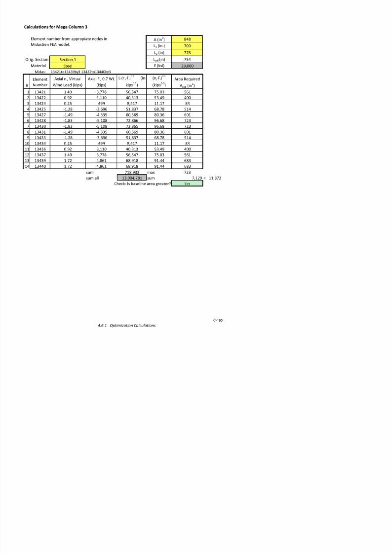
7/17/2019 Structural Design Project of Super Tall Building Chicago Spire
http://slidepdf.com/reader/full/structural-design-project-of-super-tall-building-chicago-spire 327/474
600− 400− 200− 0 2000
5 104
×
1 105
×
1.5 105
×
Z
C . c
( k i p s )
Calculations for Tension and Compression Steel
Strains
εs j i,
Ccolid j
−
Ccoli
0.003⋅←
j 0 length d( ) 1−..∈for
i 0 length Z( ) 1−..∈for
εsreturn
:=Produces an n x m matrix of strain values,
where n = number of values in d and m =
number of values in Z. Thus each column
gives the strain in the steel at distance, d,
given a particular strain in the extreme
tension steel.
εs Strains:=
600− 400− 200− 0 2000.15−
0.1−
0.05−
0
0.05
Z
S t r a i n s
Stresses
f bar εs j i,Es⋅←
f s j i,f bar← fy− f bar≤ fy≤if
f s j i,fy−← fy− f bar>if
f s j i,fy← fy f bar<if
j 0 length d( ) 1−..∈for
i 0 length Z( ) 1−..∈for
f
:=
Stresses in reinforcing steel.

7/17/2019 Structural Design Project of Super Tall Building Chicago Spire
http://slidepdf.com/reader/full/structural-design-project-of-super-tall-building-chicago-spire 328/474
f sreturng
Each column, i gives the stress
in each bar at distance d j.
f s Stresses:=
600− 400− 200− 0 2001−
10
5×
5− 104
×
0
5 104
×
1 105
×
Z
f . s ( p s i )
Forces
Fs j i,f s j i,
As j⋅← a
i d
j<if
Fs j i,f s j i,
0.85 fc⋅− As j⋅← otherwise
j 0 length d( ) 1−..∈for
i 0 length Z( ) 1−..∈for
Fsreturn
:= Forces in each bar from
stress defined above
Fs Forces:=
600 400 200 0 20040−
20−
0
20
40
F . s
( k i p s )

7/17/2019 Structural Design Project of Super Tall Building Chicago Spire
http://slidepdf.com/reader/full/structural-design-project-of-super-tall-building-chicago-spire 329/474
600− 400− 200− 0 200
d1
d2
d3
d4
d5
Z
Factors of Φ controlled by strain in exrteme tension reinforcing steel. Areas controlled by
ACI 318 118 9.3.2.2
getPhi
Phii 0.65← εs
Trows εs( ) 1−⟨ ⟩
i εy−>if
Phii
0.90← εsT
rows εs( ) 1−⟨ ⟩
i0.005−<if
Phii
0.65 εsT
rows εs( ) 1−⟨ ⟩
−
iεy−
.25
.005 εy−
⋅+← otherwise
i 0 length Z( ) 1−..∈for
Phireturn
:=
Phi getPhi:=

7/17/2019 Structural Design Project of Super Tall Building Chicago Spire
http://slidepdf.com/reader/full/structural-design-project-of-super-tall-building-chicago-spire 330/474
Summed Forces and Moments
Forcessum
PniCci
Fsi⟨ ⟩
∑+←
i 0 length Z( ) 1−..∈for
Pnreturn
:=
Pn Forcessum:=
600− 400− 200− 0 2005− 10
4
×
0
5 104
×
1 105
×
1.5 105
×
2 105
×
Z
P . n
( k i p s )
ReducePn
ΦPniPni
Phii
⋅←
i 0 length Z( ) 1−..∈for
ΦPnreturn
:=
9.3.2.2
ΦPn ReducePn:=
Momentssum
Msteel j i,Fs j i,
y d j
−( )⋅←
j 0 length d( ) 1−..∈for
MniCci
y
ai
2−
⋅ Msteel
i⟨ ⟩
∑+←
i 0 length Z( ) 1−..∈for
Mreturn
:=

7/17/2019 Structural Design Project of Super Tall Building Chicago Spire
http://slidepdf.com/reader/full/structural-design-project-of-super-tall-building-chicago-spire 331/474
Mnreturn
Mn Momentssum:=
1 106
×
1.5 106
×
( k i p * f t )
ReduceMn
ΦMniPhi
i Mni⋅←
i 0 length Z( ) 1−..∈for
ΦMnreturn
:=
ΦMn ReduceMn:=
*orces an% Moments
Negative Bending
Reinforcing Steel Layout
dtemp b4 d−:= findn2
n2i
nlength n( ) 1−( ) i−
←
i 0 length n( ) 1−..∈for
n2return
:=findsize2
size2i
sizelength size( ) 1−( ) i−
←
i 0 length size( ) 1−..∈for
size2return
:=
findd2
d2
i
d
temp length d( ) 1−( ) i−
←
i 0 length d( ) 1−..∈for
d2return
:=
size2 findsize2:=n2 findn2:=
d2 findd2:= This function calculates the distances of reinforcement bars
reltive to right side of the column geometry in order to
calculate moments with the far right face at compression
failure. The resulting "d" vector is flipped, along with the
original "n" and "size" vectors to correspond to these new
distances

7/17/2019 Structural Design Project of Super Tall Building Chicago Spire
http://slidepdf.com/reader/full/structural-design-project-of-super-tall-building-chicago-spire 332/474
distances.
Areasteel2
Asivlookup size
i BarSizes, 1, 0 1⋅ in
2
←
i 0 length d2( ) 1−..∈for
Asreturn
:=
As2 Areasteel2:=
Defined Variables
Cvalues2
dt d2length d2( ) 1−
←
Ccoli
0.003
0.003 Zi εy⋅−
dt⋅←
i 0 length Z( ) 1−..∈for
Ccolreturn
:=
Ccol2 Cvalues2:=
aStressBlock2
ai β1 Ccol2
i
⋅←
i 0 length Z( ) 1−..∈for
areturn
:=
a2 aStressBlock2:=

7/17/2019 Structural Design Project of Super Tall Building Chicago Spire
http://slidepdf.com/reader/full/structural-design-project-of-super-tall-building-chicago-spire 333/474
Strains2
εs j i,
Ccol2id2
j−
Ccol2i
0.003⋅←
j 0 length d2( ) 1−..∈for
i 0 length Z( ) 1−..∈for
εsreturn
:=Produces an n x m matrix of strain values,
where n = number of values in d and m =
number of values in Z. Thus each column
gives the strain in the steel at distance, d,
given a particular strain in the extreme
tension steel.
εs2 Strains2:=
600− 400− 200− 0 2000.15−
0.1−
0.05−
0
0.05
Z
S t
r a i n s
Stresses2
f bar εs2 j i,Es⋅←
f s j i,f bar← fy− f bar≤ fy≤if
f s j i,fy−← fy− f bar>if
f s j i,fy← fy f bar<if
j 0 length d2( ) 1−..∈for
i 0 length Z( ) 1−..∈for
f sreturn
:=
Stresses in reinforcing steel.
Each column, i gives the stress
in each bar at distance d j.

7/17/2019 Structural Design Project of Super Tall Building Chicago Spire
http://slidepdf.com/reader/full/structural-design-project-of-super-tall-building-chicago-spire 334/474
f s2 Stresses2:=
600− 400− 200− 0 2001− 10
5×
5− 104
×
0
5 104
×
1 105
×
Z
f . s ( p s i )
Forces2
Fs j i,f s2 j i,
As2 j⋅← a2
i d2
j<if
Fs j i, f s2 j i, 0.85 fc⋅− As2 j⋅← otherwise
j 0 length d2( ) 1−..∈for
i 0 length Z( ) 1−..∈for
Fsreturn
:=
Forces in each bar fromstress defined above
Fs2 Forces2:=
600− 400− 200− 0 20040−
20−
0
20
40
F . s
( k i p s )

7/17/2019 Structural Design Project of Super Tall Building Chicago Spire
http://slidepdf.com/reader/full/structural-design-project-of-super-tall-building-chicago-spire 335/474
d1
d2
d3
d4
d5
Z
AStressBlock2
Asbih2 h3+( ) a2
i⋅
a2i( )
2h1⋅
2 b2⋅
+← 0 a2i
≤ b3<if
Asbih3 b3⋅ h2 a2
i⋅+
a2i( )
2h1⋅
2 b2⋅
+← b3 a2i
≤ b2<if
Asbi h3 b3⋅ h2 a2i⋅+
h1 b2⋅
2+ h1 a2i b2−( )⋅+← b2 a2i≤ b2 b1+<if
Asbih3 b3⋅ h2 a2
i⋅+ h1 b1⋅+ h1 b2⋅+
h1 b4 a2i
−( )2
⋅
2 b2⋅
−← b2 b1+ a2i
≤ b4 b3−<if
Asbih3 b3⋅ h2 a2
i⋅+ h1 b1⋅+ h1 b2⋅+
h1 b4 a2i
−( )2
⋅
2 b2⋅
− b3 b4− a2i
+( ) h3⋅+← b4 b3− a2i
< b4≤if
i 0 length Z( ) 1−..∈for
Asb
return
:=
Asb2 AStressBlock2:=
ForceConcrete2
Cci0.85 fc⋅ Asb2i
⋅←
i 0 length Z( ) 1−..∈for
Ccreturn
:=
Cc2 ForceConcrete2:=
Compressi(e Concrete
Safety *actors
Factors of Φ controlled by strain in exrteme tension reinforcing steel. Areas controlled by
getPhi2
←T
rows εs2( ) 1−⟨ ⟩
−>
i 0 length Z( ) 1−..∈for:= 318 118 9.3.2.2

7/17/2019 Structural Design Project of Super Tall Building Chicago Spire
http://slidepdf.com/reader/full/structural-design-project-of-super-tall-building-chicago-spire 336/474
Phii 0.65←
εs2 i εy−>
if
Phii
0.90← εs2T
rows εs2( ) 1−⟨ ⟩
i0.005−<if
Phii
0.65 εs2T
rows εs2( ) 1−⟨ ⟩
−
iεy−
.25
.005 εy−
⋅+← otherwise
Phireturn
Forcessum2
PniCc2i
Fs2i⟨ ⟩
∑+←
i 0 length Z( ) 1−..∈for
Pnreturn
:=
Pn2 Forcessum2:=
600− 400− 200− 0 2005− 10
4×
0
5 104
×
1 105
×
1.5 10
5
×
2 105
×
Z
P . n
( k i p s )
ReducePn2
ΦPni Pn2i Phi2i⋅←
i 0 length Z( ) 1−..∈for
ΦPnreturn
:=
ΦPn2 ReducePn2:=
y2 b4 y−:=
Momentssum2
Msteel j i, Fs2 j i, y2 d2 j−( )⋅←
j 0 length d2( ) 1−..∈for
MniCc2i
y2
a2i
2−
⋅ Msteel
i⟨ ⟩
∑+←
i 0 length Z( ) 1−..∈for
Mnreturn
:=
Mn2 Momentssum2−:=
5 105
×
f t )
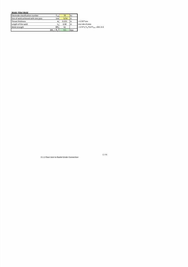
7/17/2019 Structural Design Project of Super Tall Building Chicago Spire
http://slidepdf.com/reader/full/structural-design-project-of-super-tall-building-chicago-spire 337/474
600− 400− 200− 0 2001.5− 10
6×
1− 106
×
5− 105
×
0
Z
M . n
( k i p * f
ReduceMn2
ΦMniPhi2
i Mn2i⋅←
i 0 length Z( ) 1−..∈for:=
Ag h1 b2 b1+( )⋅ h2 b4⋅+ 2 h4 h1− h2−( )⋅ b3⋅+:=Gross area of the
column
Ast As∑:=Total area of steel in the
column
PhiPn.max
ΦPn.maxi0.80 0.65⋅ 0.85 fc⋅ Ag Ast−( )⋅ fy Ast⋅+⋅←
i 0 length Z( ) 1−..∈for
ΦPn.maxreturn
:=
Maximum compression
force allowed for the
column (ACI 318-08
10.3.6.2)
ΦPn.max PhiPn.max:=
Ma+ Compression *orce
,+ial )ension
Strength of the column under tension is equal to the yield strength of the reinforcement in tension
Ptension
Ptify− Asi⋅←
i 0 length d( ) 1−..∈for
Ptreturn
:=
Pt Ptension:=
Pnt Pt∑:= Net capacity in pure tension
ΦPnt 0.9 Pnt⋅:= Design compacity in pure tension: Φ = 0.9
Mtension
MtiPti
y di
−( )⋅←
i 0 length d( ) 1−..∈for:=

7/17/2019 Structural Design Project of Super Tall Building Chicago Spire
http://slidepdf.com/reader/full/structural-design-project-of-super-tall-building-chicago-spire 338/474
Mtreturn
Mt Mtension:=
Mnt Mt∑:= Net moment in pure tension
The following vectors are used merely for plotting purposes: plotting a line between the net
tension force / moment point and the points corresponding to the last force / moment pairs
from the P.n, M.n, ΦP.n, and ΦM.n vectors respectively
Pnt1
Pnt
Pnlength Pn( ) 1−
:=
Mnt1
Mnt
Mnlength Mn( ) 1−
:=
Pnt2
Pnt
Pn2length Pn2( ) 1−
:=
Mnt2
Mnt
Mn2length Mn2( ) 1−
:=
ΦPnt1
ΦPnt
ΦPnlength ΦPn( ) 1−
:=
ΦMnt1
ΦMnt
ΦMnlength ΦM
n
( ) 1−
:=
ΦPnt2
ΦPnt
ΦPn2length ΦPn2( ) 1−
:=
ΦMnt2
ΦMnt
ΦMn2length ΦMn2( ) 1−
:=
,+ial )ension
$esign Loa%s
Pg
789kip
636kip
0
:=
Mg
2991ftkip
1600ftkip
0
:=

7/17/2019 Structural Design Project of Super Tall Building Chicago Spire
http://slidepdf.com/reader/full/structural-design-project-of-super-tall-building-chicago-spire 339/474
0
2046.632−
18158.031
38362.694
58567.358
78772.021
98976.684
119181.347
139386.01
159590.674
179795.337
200000
Column Interaction Diagram
Moment
A x i a l L o a d ( k i p s )
427.979−
23.316−
381.347
786.01
1190.674
1595.337
2000
Column Interaction Diagram
i a l L o a d ( k i p s )
-1.50 -1.20 -0.90 -0.60 -0.30 0 0.30 0.60 0.90 1.20 1.50
(kip*ftx10^6)

7/17/2019 Structural Design Project of Super Tall Building Chicago Spire
http://slidepdf.com/reader/full/structural-design-project-of-super-tall-building-chicago-spire 340/474
2046.632−
1641.969−
1237.306−
832.642− A x
-1.50 -1.20 -0.90 -0.60 -0.30 0 0.30 0.60 0.90 1.20 1.50
C r e a t e d b y :
J A C , M Z
5 / 1 / 2 0 1 2
i ! "
( e # 1 0 )
H / 4 0 0
H / 5 0 0
4
1
9
9 2 0
* + 1
4
2 '
9 0 '
9 2 0
* + 1
4
4 0
0 0
0 0
* + 2
4
5 9 9
4
* + '
4
5 4 2
* + 4
4
4 0
5
0
* + 5
2 1 5
1 4 0
1 5
1
1 4 - 0 5
4
4 5
5 1
5
* +
4
4 0
5 0 9
5 1 2
* +
4
4 0 0
5 0 0
5 1 2
* +
4
4 1
0 2
0
* +
2 1 5
1 2 1
1 5 1
1 2
1 4 - 5 5 0
' 4
4
4 0
* + 9
2
' ' 5
' 4
* + 1 0
1 9 5
2 4 4
2 5 0
* + 1 1
1 2
1 5 9
1 2
1 4 - 5 5 0
2 1 5
'
4
5 1 "
1 4 - 1
1 2 '
1 5 '
1 2
1 4 - 5 5 0
1 0
1 ' 5
1 ' 4
1 4 - 4 5 5
9
1 0 1
1 4 - ' 4 2
%
* a k e r 1 9 9 a e r ( $ s i ! e # $ a t i ! 1 0 s 3 ! 3 e r
e ) t 6 % $ t e t i % a & %
e % b e r s e 6 t i ! s r
e s i s t i ! s y s t e % " . 3 e s e a r e a s a r e 6 % a r e d t b a s
e & i ! e a r e a s a ! d b $ i & t 7 $
s e 6 t i ! s s a t i s y i !
O p t i m i z e d
A r e a ( i n 2 )
B a s e l i n e
A r e a ( i n 2 )
O p t i m i z e d
A r e a ( i n 2 )
P r o p o s e d
S e c t i o n
A r e a P r o ! i d e d
( i n 2 )
4 . 6
E n e r g y M e t h o d O p t i m i z a t i o
n

7/17/2019 Structural Design Project of Super Tall Building Chicago Spire
http://slidepdf.com/reader/full/structural-design-project-of-super-tall-building-chicago-spire 341/474
O p t i m i z a t i o n
0 0
Δ = H / 4 0 0 0
1
3 d t i % i a t i ! r %
% b e r s t 3 e & a t e r a & r
% i ! e d "
! s & r s 4 7
s 1 7 4
s 1 7 4
! s & r s 5 7 1
m e r
% ! s & r s 2 7 '
! s & r s 7 9 9
! s & r s 1 0 0 7 1 0
% ! s & r s 1 0 9 7 1 1 0
s & r s 1 1 1 7 1 2 2
! s & r s 1 7 2
! s & r s 2 9 7 '
% ! s & r s ' 7 ' 9
! s & r s 4 0 7 5 2
! s & r s 5 7 '
! s & r s 4 7 1
s & r s 1 2 ' 7 1 ' '
s & r s 1 ' 4 7 1 4 4
e
d
1
, 2
8 > 1
* a ! k
2
8 > 2
* a ! k '
. r a ! s '
8 > '
* a ! k 4
4
2 1 5
4
2 1 5
2 1 5
5 1 2
2 5 0
1 0 1
5 1 2
' 4
1 ' 4
5
4 0
1 2
* +
* + 1 1
1 4 - ' 4 2
+5
* +
* + 1 0
1 4 - 4 5 5
+
* +
* + 9
1 4 - 5 5 0
2
7 1
7 '
7 2 5
7 4
7
7
7 1
1 4 - 1
1 4 - 0 5
1 4 - 5 5 0
1 4 - 5 5 0
0
1
1 2
1 2
5 2
4 . 6
E n e r g y M e t h o d O p t i m i z a t i o
n

7/17/2019 Structural Design Project of Super Tall Building Chicago Spire
http://slidepdf.com/reader/full/structural-design-project-of-super-tall-building-chicago-spire 342/474
& a r e r a & $ e s i ! r e
a
* a ! k 1
. r a ! s 1
4
4
0 0
* + 4
* + '
* + 5
* + 2
* +
7 1 1
7 2
1
0
4.6.1 Optimization Calculations
Steel Reduction Calculation
1 7 754 848 920 2,589 2,809 -220
2 14 754 848 920 5,178 5,618 -440
3 252 158 848 800 19,539 18,433 1,106
4 252 158 848 768 19,539 17,696 1,843
5 189 158 848 688 14,655 11,890 2,7656 21 327 848 608 3,370 2,416 954
7 21 530 215 178 1,386 1,147 239
8 273 158 848 576 21,168 14,378 6,790
9 231 158 848 512 17,911 10,814 7,097
10 168 158 848 512 13,026 7,865 5,161
11 21 342 848 608 3,522 2,526 997
12 21 475 215 162 1,240 934 306
13 196 158 688 480 12,330 8,602 3,72814 154 158 688 347 9,688 4,886 4,802
15 140 158 688 250 8,807 3,200 5,607
16 14 316 688 162 1,763 415 1,348
17 14 432 215 51.8 752 181 571
18 168 158 688 162 10,577 2,491 8,087
19 154 158 688 134 9,696 1,888 7,807
20 154 158 688 101 9,696 1,423 8,273
vol reduction in steel (ft3) 186,432 119,613 66,819
wt reduction in steel (ton) 46,608 29,903 16,705
% reduction 36
!se line "olu#e $ &'
"olu#e !n*e $ !seline - +ti#ied
+ti#ied
"olu#e (ft3)
"olu#e
!n*e (ft3)
u#/er of
le#ents
en*t
(in)
!seline 're!
' (in2)
+ti#ied
're! (in2)
!seline
"olu#e (ft3)

7/17/2019 Structural Design Project of Super Tall Building Chicago Spire
http://slidepdf.com/reader/full/structural-design-project-of-super-tall-building-chicago-spire 343/474
"olu#e !n*e $ !seline +ti#ied
Steel Tonnage for Increased Performance
500 4.0 0 47 30.0
526 3.8 5 47 31.5
556 3.6 10 47 33.2
588 3.4 15 47 35.2
625 3.2 20 47 37.4
rift () !seline
esi*nrift (ft)
% rift
eduction
+ti#ied
esi*n
47
30.0
31.5
33.235.2
37.4
30
35
40
45
50
0 5 10 15 20
S t e e l , 1 0 0 0 t
o n s
Reduction of !rift
!seline esi*n +,ti#i-ed esi*n

7/17/2019 Structural Design Project of Super Tall Building Chicago Spire
http://slidepdf.com/reader/full/structural-design-project-of-super-tall-building-chicago-spire 344/474
Calculations for "ega Column #
' (in2) 848
1 (in.) 709
2 (in) 776
ection 1 eff (in) 754
!teri!l teel (si) 29,000
id!s:
le#ent
u#/er
'i!l ni, "irtu!l
;ind o!d (is)
'i!l <i, 0.7 ;
(is)
=(ni=<i)0.5
(in-
is0.5
)
(ni=<i)0.5
(is0.5
)
're! e>uired
're> (in2)
1 13421 1.49 3,778 56,547 75.03 561
2 13422 0.92 3,110 40,313 53.49 400
3 13424 0.25 499 8,417 11.17 83
4 13425 -1.28 -3,696 51,837 68.78 514
5 13427 -1.49 -4,335 60,569 80.36 601
6 13428 -1.83 -5,108 72,866 96.68 723
7 13430 -1.83 -5,108 72,865 96.68 7238 13431 -1.49 -4,335 60,569 80.36 601
9 13433 -1.28 -3,696 51,837 68.78 514
10 13434 0.25 499 8,417 11.17 83
11 13436 0.92 3,110 40,313 53.49 400
12 13437 1.49 3,778 56,547 75.03 561
13 13439 1.72 4,861 68,918 91.44 683
14 13440 1.72 4,861 68,918 91.44 683
su# 718,932 #! 723
su# !ll 13,004,781 su# 7,129 ? 11,872
@esec: As /!seline !re! *re!terB
13421to13439/C3 13422to13440/C3
le#ent nu#/er fro# !roi!te nodes inid!sDen <' #odel.
+ri*. ection
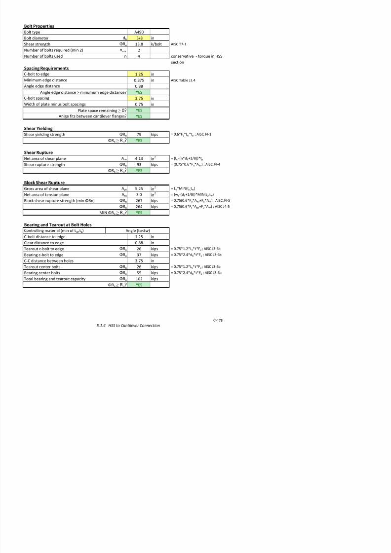
7/17/2019 Structural Design Project of Super Tall Building Chicago Spire
http://slidepdf.com/reader/full/structural-design-project-of-super-tall-building-chicago-spire 345/474
C r e a t e d
b y :
J A C
5 / 1 / 2 0 1 2
3 8
3 0
4 0
5
9 2 0
8 9 4
Y e s
3 8
3 0
4 0
5
9 2 0
9 0 3
Y e s
3 2
2 4
4 0
5
8 0 0
7 9 8
Y e s
3 2
2 4
3 6
5
7 6 8
7 4 7
Y e s
2 8
2 0
3 6
5
6 8 8
6 7 5
Y e s
2 8
2 0
3 6
4
6 0 8
5 8 5
Y e s
2 8
2 0
3 2
4
5 7 6
5 7 0
Y e s
2 8
2 0
2 4
4
5 1 2
5 0 7
Y e s
2 8
2 0
2 4
4
5 1 2
4 9 8
Y e s
2 8
2 0
2 6
5
6 0 8
6 0 0
Y e s
2 8
2 0
2 0
4
4 8 0
4 6 5
Y e s
3 4 7
3 3 3
Y e s
2 5 0
2 4 3
Y e s
s i d e a r e a
t p i t x b
p ! " s i t e r i # r a r e a
x t p i t x $ d % 2 t p s i d
e &
(
t e r i # r ) ! a t e s
, i d e ) ! a t e
- .
'
# t a ! * e p t +
d $ i &
( t e r i # r
* e p t + d i t
' # t a ! W i d t +
b $ i &
# ( t e r i # r
) ! a t e
s
s x 3
p ! a t e s e ! d e d t # t + e t #
p a d b # t t # ! a e s
x 2
p ! a t e s e ! d e d t # t + e t #
p a d b # t t # ! a e s
+ e
# p t i i ; a t i # s p r e a d s + e e
t & < t + i s t # # ! a b e " s e d t # d e s i a b " i ! t % " p # ! "
" s i s t e e ! p ! a t e s
$ b y
t r i a ! a d e r r # r & =
A r e a ) r # i d e d
A p r #
$ i 2 &
A r e a ? e " i r e d
A r e
$ i 2 &
4 . 6 . 2 R e
s i z i n g o f B u i l t - U p M e m b e r s

7/17/2019 Structural Design Project of Super Tall Building Chicago Spire
http://slidepdf.com/reader/full/structural-design-project-of-super-tall-building-chicago-spire 346/474
4 4 4 4 4 4 4 4 4 4 4
! W i d t +
t - U p M e m b e r s
( t e r i # r
' + i e s s t p i t
i t + 2 2
i t + 2 2
t i # a ! a r e a $ r # t
t + a t r # s s s e t i # $
5.0 Connection Design
5.1 Typical Connections
5.1.1 Welded Column Splice 163
5.1.2
Floor Joist to adial !irder Connection 16"
5.1.3
!irder to Column Connections
5.1.3.1 Fixed Radial Elements to Column Connection 171
5.1.3.2 Pinned Circumferential Girder to Column Connection 175
5.1.#
$SS to Cantile%er Connection 1&&
5.1.5
adial !irder to Concrete Core 1"0
5.1.5.1 Single Plate Connection 181
5.1.5.2 Concrete nc!or "olt #esign 185
5.2 'ase o( )ega*Column Connection 1"+
5.2.1 )ega*Column to Caisson Connection 1+0
5.2.2 Caisson Cap )oment ein(orcement 1+#
5.3 ,utrigger Connections 1+6
5.3.1
'ottom o( ,utrigger to Column Connection 1+&
5.3.2
Top o( ,utrigger to Core 1++

7/17/2019 Structural Design Project of Super Tall Building Chicago Spire
http://slidepdf.com/reader/full/structural-design-project-of-super-tall-building-chicago-spire 347/474
p gg
5.1.1 Welded Column Splice KMC 4/27/2012
Bank Color Key: User Input
Column Location Constant/Preious Calc!
Column "ype Calc/Lookup
#es Passes C$eck
%o &ails C$eck
'(ial &orce P) 1*+,2 kips Column Splice Elevation:
-$ear . y y 2!2 kips
-$ear . 13 kips
"orsion "u .0!4, kip.in
Moment . y My 140 kip.inMoment . M 1!1 kip.in
Column Details
Column -ection Properties
Built.up ept$ 5 23!0 in
Built.up 6i5t$ 8 ,+!0 in
Memer "$ickness t 4!0 in
9ross 'rea ') +33 in2
( . a5ius o8 9yration r( 11!, in
y . a5ius o8 9yration ry 11!0 in Column Plan View:
Create5 y:
2 . ,
"rans8er
BU.2
"$is column splice is use5 8or t$e me)a.column an5 trans8er column connections! "$e connection is ma5e upo8 pre.8aricate5 steel memers t$at are <el5e5 to)et$er on site! In t$is calculation t$e capacity o8 t$e <el5
an5 memers are c$ecke5!
0.9D+1.6Wo!ces "!om #$D%S "o! &oad Case:
#esIs Column -plice =kay>
Welded ColumnSplice
SamplePre-fabricated
Node
depth
plate length
plate width

7/17/2019 Structural Design Project of Super Tall Building Chicago Spire
http://slidepdf.com/reader/full/structural-design-project-of-super-tall-building-chicago-spire 348/474
"op Column Properties
Lateral Unrace5 Len)t$ L 13 in
;88ectie Len)t$ &actor K 0!+
Bottom Column Properties
Welds
Column
width
d h
Plate Details
Plate ' Properties
"$ickness tp 0!7 in6i5t$ <p 14 in ?5imension perpen5icular to column@
Len)t$ lp + in ?5imension parallel to column@
Aproperties <ill e summe5 as necessary
Plate B Properties
"$ickness tp 0!7 in
6i5t$ <p 14 in ?5imension perpen5icular to column@
Len)t$ lp + in ?5imension parallel to column@
Aproperties <ill e summe5 as necessary
-teel Properties . Plate
#iel5 -tren)t$ &y 0 ksi
"ensile -tren)t$ &u + ksi
Weld Details
6el5 Properties
&iller Metal Class! -tren)t$ &; 70 ksi
6el5 -tren)t$ &< 42 ksi 0!+0A&;A?1!0D0!0Asin?E@1!
@ <$ere E 0 F 'I-C G2.
E is assume5 to e 0* as an)le o8 8orce is unkno<n
Plate ' 6el5 Properties
Le) Len)t$ 0!2 in ?same 8or ot$ <el5s* 8or construction purposes@"$roat Len)t$ 0!,4 in le) len)t$ / cos?4
o@
6el5 Len)t$ per -i5e L< 40 in
6el5 'rea '< 14!1 in2
Min! Le) Len)t$ o8 6el5 0!2 in per 'I-C tale G2!4
Ma(! Le) Len)t$ o8 6el5 0!+33 in ?5epen5s on plate t$ickness@F G2.2
Plate B 6el5 PropertiesLe) Len)t$ 0 2 in

7/17/2019 Structural Design Project of Super Tall Building Chicago Spire
http://slidepdf.com/reader/full/structural-design-project-of-super-tall-building-chicago-spire 349/474
Le) Len)t$ 0!2 in
"$roat Len)t$ 0!,,+ in le) len)t$ / cos?4o@
6el5 Len)t$ per -i5e L< 40 in
6el5 'rea '< 14!1 in2
Min! Le) Len)t$ o8 6el5 0!12 in per 'I-C tale G2!4
Ma( Le) Len)t$ o8 6el5 0 +33 in ?5epen5s on plate t$ickness@F G2.2
'ension C(ec)s
Plate ' "ension C$eck
Ma(! "ensile Loa5 "u 41, kipsUlt! #iel5in) "ens! Capacity H"n.yiel5 47, kips 0!0A&yA') F 'I-C 2.1
-$ear La) &actor U 0!1 1.?eccentricty@/?<el5 len)t$@ F 'I-C tale ,!1
;88ectie %et 'rea 'e 10!4 in2
'nU F 'I-C ,.1F 'n ') B4.,F ') tA<
Ult! upture "ens! Capacity H"n.rupture 07 kips 0!0A&uA'e F 'I-C 2.2
Minimum H"n 47, kips min? H"n.yiel5 * H"n.rupture @
"u J"n > #es 1
Plate B "ension C$eck
Ma(! "ensile Loa5 "u 403 kips
Ult! #iel5in) "ens! Capacity H"n.yiel5 47, kips 0!0A&yA') F 'I-C 2.1
-$ear La) &actor U 0!1 1.?eccentricty@/?<el5 len)t$@ F 'I-C tale ,!1
;88ectie %et 'rea 'e 10!4 in2
'nU F 'I-C ,.1F 'n ') B4.,F ') tA<
Ult! upture "ens! Capacity H"n.rupture 07 kips 0!0A&uA'e F 'I-C 2.2
Minimum H"n 47, kips min? H"n.yiel5 * H"n.rupture @
"u J"n > #es 1
Col* ' -i5e "ension C$eck
Ma(! "ensile Loa5 "u 1*+,4 kips
Ult! #iel5in) "ens! Capacity H"n.yiel5 ,0*+0 kips 0!0A&yA') F 'I-C 2.1
-$ear La) &actor U 0!+0 1.?eccentricty@/?<el5 len)t$@ F 'I-C tale ,!1;88ectie %et 'rea 'e 447 in
2 'nU F 'I-C ,.1F 'n ') B4.,F ') tA<
Ult! upture "ens! Capacity H"n.rupture 21*301 kips 0!0A&uA'e F 'I-C 2.2
Minimum H"n 21*301 kips min? H"n.yiel5 * H"n.rupture @
"u J"n > #es 1
Col* B -i5e "ension C$eck
Ma(! "ensile Loa5 "u 1*+,4 kipsUlt #iel5in) "ens Capacity H" ,0 +0 kips 0 0A& A' F 'I-C 2 1
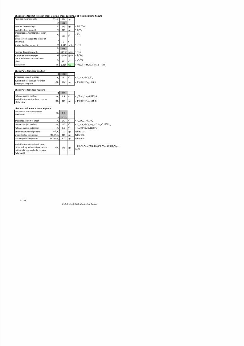
7/17/2019 Structural Design Project of Super Tall Building Chicago Spire
http://slidepdf.com/reader/full/structural-design-project-of-super-tall-building-chicago-spire 350/474
Ult! #iel5in) "ens! Capacity H"n.yiel5 ,0*+0 kips 0!0A&yA') F 'I-C 2.1
-$ear La) &actor U 0!0 1.?eccentricty@/?<el5 len)t$@ F 'I-C tale ,!1
;88ectie %et 'rea 'e ,73 in2
'nU F 'I-C ,.1F 'n ') B4.,F ') tA<
Ult! upture "ens! Capacity H"n.rupture 13*447 kips 0!0A&uA'e F 'I-C 2.2
Minimum H"n 13*447 kips min? H"n.yiel5 * H"n.rupture @
Comp!ession C(ec)s
"op Column Compression C$ecks
-len5erness atio !,+ KL/rF G4.+KL/r 2 > #es 1
Ma(! Comp! Loa5 Pu 0 kips
Ult! Comp! Capacity HPn ,0*+0 kips 0!0A&yA')F G4.+
Pu JPn > #es 1
Bottom Column Compression C$ecks
-len5erness atio 2!,4 KL/rF G4.+KL/r 2 > #es 1
Ma(! Comp! Loa5 Pu 0 kips
Ult! Comp! Capacity HPn ,0*+0 kips 0!0A&yA')F G4.+
Pu JPn > #es 1
Column Bearin) C$eck
Ma(! Bearin) Loa5 u 0 kipsUlt! Bearin) Capacity Hn 4+*440 kips 0!7A1!3A&yA'p F 'I-C G7.1
u Jn > #es 1

7/17/2019 Structural Design Project of Super Tall Building Chicago Spire
http://slidepdf.com/reader/full/structural-design-project-of-super-tall-building-chicago-spire 351/474
Weld C(ec)s
"otal 6el5 'rea '"=" +!+ in2
2A?'<Plate'D'<PlateB@
Plate ' 6el5 C$eck
'rea o8 <el5 ' '' 14!142 in2
Ma(! ( &orce &( 403 kips ma(?0* ?Pu@A''/'"=" D as?M@/5@
Ma(! y &orce &y 0!7,0 kips as?y@A''/'"="
Ma(! &orce & ,! kips as?@A''/'"=" D as?"@A''/'"="/?5/2@
esultant &orce & 410 kips srt?&(2D&y
2D&
2@
Plate ' 6el5 Capacity Jn.<el5 44 kips '<A&< F 'I-C G2.,
& Jn.<el5 > #es 1
Plate ' Capacity Jn.plate 1*12 kips L<AtpA&y F 'I-C G2.2
& Jn.plate > #es 1
Column -i5e ' Capacity Jn.col si5e +*000 kips L<AtA&y F 'I-C G2.2
& Jn.col si5e > #es 1
Plate B 6el5 C$eck
'rea o8 <el5 B 'B 14!1 in2
2A?'<Plate'D'<PlateB@
Ma(! ( &orce &( 412 kips ma(?0* ?Pu@A'B/'"="D as?My@/8
Ma(! y &orce &y 0!74, kips as?y@A'B/'"=" D as?"@A'B/'"="/?8 /2@
Ma(! &orce & ,! kips as?@A'B/'"="
esultant &orce & 414 kips srt?&(2D&y2D&2@
Plate ' 6el5 Capacity Jn.<el5 44 kips '<A&< F 'I-C G2.,
& Jn.<el5 > #es 1
Plate ' Capacity Jn.plate 1*12 kips L<AtpA&y F 'I-C G2.2
& Jn.plate > #es 1
Column -i5e ' Capacity Jn.col si5e +*000 kips L<AtA&y F 'I-C G2.2
& Jn.col si5e > #es 1
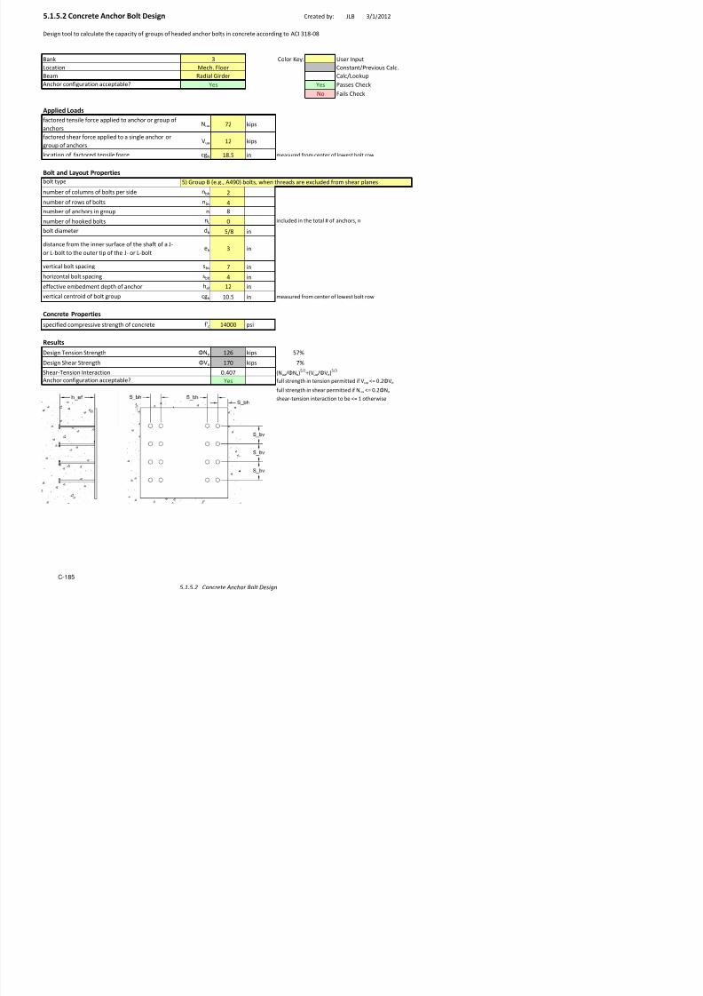
7/17/2019 Structural Design Project of Super Tall Building Chicago Spire
http://slidepdf.com/reader/full/structural-design-project-of-super-tall-building-chicago-spire 352/474
1
5.1.2 Floor Joist to Radial Girder Connection Created by: JDM 3/13/12
Bank: 4 Color Key: User Input
Locaton: !ypcal Lar"est #loor $ost Constant/%re&ous Calc'
Calc/Lookup
(es %asses C)eck
*o #als C)eck
C+bolt Center o, Bolt
Design Adequate?
-ertcal Load at Connecton .u 24 kps
Girder Properties
rder secton 0secton 21
rder ,lan"e 0dt) b, ' n
rder ,lan"e t)ckness t, 5' nrder 0eb t)ckness t0 5'45 n
rder dept) d 21'1 n
rder k1 k1 5'61 n
rder clear space ! 17'46 n
Joist Properties
Jost secton 8secton 12 22
Jost ,lan"e 0dt) b, 4'53 n
J t ,l t) k t 5 42
#ro< Jost Des"n
Des"n tool ,or t)e ,loor $ost to t)e radal "rder connecton usn" a sn"le an"le bolted nto t)e 0eb o, eac)
<e<ber'
PASS
9n"le9n"le
JostJost
/rder

7/17/2019 Structural Design Project of Super Tall Building Chicago Spire
http://slidepdf.com/reader/full/structural-design-project-of-super-tall-building-chicago-spire 353/474
Jost ,lan"e t)ckness t, 5'42 n
Jost 0eb t)ckness t0 5'2 n
Jost dept) d 12'3 n
Jost k1 k1 5'2 n
Jost clear space ! 11'5 n
Bolt Properties
Bolt type 9475
Bolt da<eter db /6 n
=)ear stren"t) >.n 13'6 k/bolt 9I=C !+1
*u<ber o, bolts re;ured ?<n 2@ n 2
Spacing Requireents
1'2 n
5'6 n 9I=C !able J3'4
5'74 n
9n"le ed"e dstance A <nu<u< ed"e dstance (=
3' n
5' n
%late space re<ann" ≥ 5 (=
(=(=
S!ear "ielding
=)ear yeldn" stren"t) >.n kps 5'E#yELpEtp F 9I=C J4+1
>.n ≥ .u (=
S!ear Rupture*et area o, s)ear plane 9n& 1'3 n
2 ?Lp+?nEdbG1/6@@Etp
=)ear rupture stren"t) >.n 34 kps ?5'E5'E#uE9n&@ F 9I=C J4+4
>.n ≥ .u (=
Bloc# S!ear Rupture
ross area o, s)ear plane 9"& 1'62 n2 LpEMI*?tpHt0@
*et area o, tenson plane 9nt 5'6 n2 ?0p+?dbG1/6@@EMI*?tpHt0@
Block s)ear rupture stren"t) ?<n >.n@ >.n 6 kps 5'?5'E#uE9n&G#uE9nt@ F 9I=C J4+
>. 62 kps 5 ?5 E# E9 G# E9 @ F 9I=C J4
C+bolt to ed"e
Mn<u< ed"e dstance
9n"le ed"e dstance
C+bolt spacn"
8dt) o, plate <nus bolt spacn"s
Jost ,ts bet0een "rder ,lan"es9n"le ,ts bet0een $ost ,lan"es

7/17/2019 Structural Design Project of Super Tall Building Chicago Spire
http://slidepdf.com/reader/full/structural-design-project-of-super-tall-building-chicago-spire 354/474
>.n 62 kps 5'?5' #y 9"&G#u 9nt@ F 9I=C J4+
MI* >.n ≥ .u (=
Bearing and $earout at Bolt %oles
Controlln" <ateral ?<n o, t0Htp@ Jost 8eb
&eld' Fillet &eld
lectrode class,caton nu<ber #:: 35 ks
=e o, 0eld ac)e&ed 0t) one pass se /1 n!)roat t)ckness 0t 5'221 n D 5'353Ese
Len"t) o, t)e 0eld L0 '55 n one sde o, plate
8eld stren"t) >.n 42 D 5'3EteEL0E5'E#:: F 9I=C J2+4
>.n ≥ .uB (= kps

7/17/2019 Structural Design Project of Super Tall Building Chicago Spire
http://slidepdf.com/reader/full/structural-design-project-of-super-tall-building-chicago-spire 355/474
5.1.3.1 Fixed Radial Elements to Column Connection
Bank: 4 Color Key: User Input
Location: Typical Column Constant/Previous Calc.
Calc/Lookup
Yes Passes Check
o !ails Check
C"#olt Center o$ Bolt
Radial Girder to Column Connection
Design Adequate?
%oment at Connection %u &'&(' Kip"in
%oment )rm *m +,.( in
!orce to #e -esiste* #y !lane Bolts -m 00 Kips 1 %u/*m
2ertical Loa* at Connection -v ++' Kips !rom %i*as 3en %o*el
Girder Properties
3ir*er section section +& 5 ,
Beam $lane 6i*th #$ ,.4 in
Beam $lane thickness t$ '.,0 in
Beam 6e# thickness t6 '.0&0 in
Beam *epth * +& 4 in
Create* #y: 89 4/+&/&+
PA
9esin tool $or the ra*ial an* cantilever ir*ers to the e5terior columns usin t6o anles 6el*e* to the columnan* #olte* to the $lane o$ the ir*er to resist the moment. To resist the shear there are t6o plates 6el*e* to
the column an* #olte* to the 6e# o$ the incomin ir*er.
Plates
:hear !orce Taken #y 4e#
%oment Taken #y !lan.e
Column
3ir*er

7/17/2019 Structural Design Project of Super Tall Building Chicago Spire
http://slidepdf.com/reader/full/structural-design-project-of-super-tall-building-chicago-spire 356/474
Beam *epth * +&.4 in
Beam k& K& '.,, in
Plate Properties
Plate thickness tp &.0' in
!olt Properties
e#Bolt type )4;'
Bolt *iameter *# & &/, in
hear strenth criteria <-n 44.7 k/#olt )IC T7"&
um#er o$ #olts re=uire* >min +? n 0
!lane
Bolt type )4;'
Bolt *iameter *# & &/, in
hear strenth criteria <-n 44.7 k/#olt )IC T7"&
um#er o$ #olts re=uire* >min +? n ,
pacing Requirements
+.4' in
&.7, in
&.70 in )IC Ta#le 8.4
Plate e*e *istance @ minumum e*e *istanceA Y
&.+0 in
+.+' in
Plate space remainin ≥ 'A Y
Plate "ear #ielding $Designed %or Flange &nl'(
hear yiel*in strenth <-n 04' kips 1 '.(!yLptp D )IC 84"&
<-n ≥ -uA Y
Plate "ear Rupture $Designed %or Flange &nl'(
et area o$ shear plane )nv ;.0( in+ 1 >Lp">n*#E&/,??tp
Plate shear rupture strenth <-n +,' kips 1 >'.70'.(!u)nv? D )IC 84"4
<-n ≥ -uA Y
C"#olt to e*e
Plate e*e *istance
%inimum e*e *istance
C"#olt spacin
i*th o$ plate minus #olt spacins

7/17/2019 Structural Design Project of Super Tall Building Chicago Spire
http://slidepdf.com/reader/full/structural-design-project-of-super-tall-building-chicago-spire 357/474
!loc) "ear Rupture *e+
e#3ross area o$ shear plane )v (.&, in
+ 1 Lp%I>tpFt6?
et area o$ tension plane )nt .' in+ 1 >6p">*#E&/,??%I>tpFt6?
Block shear rupture strenth >min <-n? <-n 4+4 kips 1 '.70>'.(!u)nvE!u)nt? D )IC 84"0
<-n +, kips 1 '.70>'.(!y)vE!u)nt? D )IC 84"0
%I <-n ≥ -uA Y
!lane
3ross area o$ shear plane )v &'.'+ in+ 1 Lp%I>tpFt6?
et area o$ tension plane )nt 4., in+ 1 >6p">*#E&/,??%I>tpFt6?
Block shear rupture strenth >min <-n? <-n 0&4 kips 1 '.70>'.(!u)nvE!u)nt? D )IC 84"0
<-n 4'0 kips 1 '.70>'.(!y)vE!u)nt? D )IC 84"0
%I <-n ≥ -uA Y
!earing and ,earout at !olt -oles *e+
e#
Controllin material >min o$ t6Ftp?
C"#olt *istance to e*e +.4' in
Tearout c"#olt to e*e <-n 0 kips 1 '.70&.+Lct!u D )IC 8"(a
Bearin c"#olt to e*e <-n (, kips 1 '.70+.4*#t!u D )IC 8"(a
C"C *istance #et6een holes .'' in
Tearout center #olts <-n 0 kips 1 '.70&.+Lct!u D )IC 8"(a
Bearin center #olts <-n (, kips 1 '.70+.4*#t!u D )IC 8"(a
Total #earin an* tearout capacity <-n +(4 kips
<-n ≥ -uA Y
FlangeControllin material >min o$ t6Ftp?
C #olt *istance to e*e + 4' in
Plate >tpGt6?
Beam e# >t6Gtp?
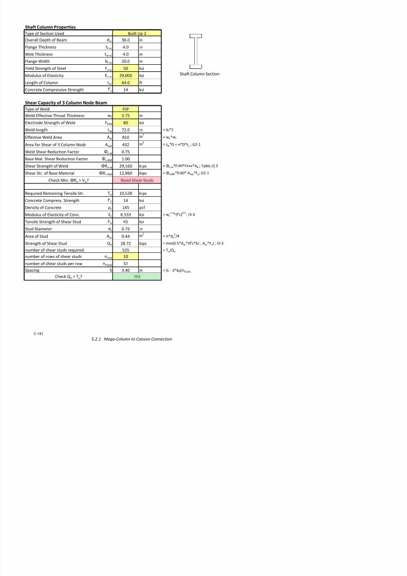
7/17/2019 Structural Design Project of Super Tall Building Chicago Spire
http://slidepdf.com/reader/full/structural-design-project-of-super-tall-building-chicago-spire 358/474
C"#olt *istance to e*e +.4' in
Tearout c"#olt to e*e <-n ,7 kips 1 '.70&.+Lct!u D )IC 8"(a
Bearin c"#olt to e*e <-n &&' kips 1 '.70+.4*#t!u D )IC 8"(a
C"C *istance #et6een holes .'' in
T t t # lt <- ,0 ki ' 70& +L t! )IC 8 (
*elds Fillet *eld
e#lectro*e classi$ication num#er !HH 7' ksi
ie o$ 6el* 6ith one pass sie & in
Throat thickness 6t '.7'7 in 1 '.7'7sie
Lenth o$ the 6el* L6 &&.'' in one si*e o$ plate
el* strenth <-n +40 kips 1 '.70teL6'.(!HH D )IC 8+"4
<-n ≥ -uA Y
!lane
lectro*e classi$ication num#er !HH 7' ksi
ie o$ 6el* 6ith one pass sie & in
Throat thickness 6t '.7'7 in 1 '.7'7sie
Lenth o$ the 6el* L6 +&.'' in one si*e o$ plate
el* strenth <-n 4(, kips 1 '.70teL6'.(!HH D )IC 8+"4
<-n ≥ -uA Y

7/17/2019 Structural Design Project of Super Tall Building Chicago Spire
http://slidepdf.com/reader/full/structural-design-project-of-super-tall-building-chicago-spire 359/474
5.1.3.2 Pinned Circumferential Girder to Column Connection Created by: JDM 3/13/12
Bank: 4 Color Key: User Input
Locaton: !ypcal Colu"n Constant/#re$ous Calc%
Calc/Lookup
&es #asses C'eck
(o )als C'eck
C*bolt Center o+ Bolt
Design Adequate?
,ertcal Load at Connecton -u . Kps )ro" Mdas 0en Model
Girder Properties
0rder secton secton 14 43
Bea" +lane dt' b+ 5%6 n
Bea" +lane t'ckness t+ 6%.3 n
Bea" eb t'ckness t 6%36. n
Bea" dept' d 13% n
Bea" k1 k1 1%66 n
Plate Properties
#late t'ckness tp 6%.6 n
#late lent' Lp 16%6 n
#late dt' p 7%6 n
plate yeldn strent' + y .6 ks
plate ult"ate strent' + u 7. ks
Bolt Properties
Desn tool +or t'e crcu"+erental rders to t'e eteror colu"ns usn a snle plate elded to t'e colu"n andbolted to t'e eb o+ t'e rder%
PASS
#late
0rderColu"n

7/17/2019 Structural Design Project of Super Tall Building Chicago Spire
http://slidepdf.com/reader/full/structural-design-project-of-super-tall-building-chicago-spire 360/474
Bolt type 8496
Bolt da"eter db /5 n
'ear strent' crtera ;-n 2%1 k/bolt 8IC !*1
(u"ber o+ bolts re<ured ="n 2> n 3
Spacing equirements
2%66 n
1%.6 n1%2. n 8IC !able J3%4
#late ede dstance ? "nu"u" ede dstance@ &A
3%66 n
6%66 n
#late space re"ann ≥ 6@ &A
Plate S!ear "ielding
'ear yeldn strent' ;-n 1.6 kps 6%7)yLptp 8IC J4*1
;-n ≥ -u@ &A
Plate S!ear upture
(et area o+ s'ear plane 8n$ 3%. n2 =Lp*=ndbE1/5>>tp
#late s'ear rupture strent' ;-n 116 kps =6%.6%7)u8n$> 8IC J4*4
;-n ≥ -u@ &A
Bloc# S!ear upture
0ross area o+ s'ear plane 8$ 3%6. n2 LpMI(=tpFt>
(et area o+ tenson plane 8nt 1%. n2 =p*=dbE1/5>>MI(=tpFt>
Block s'ear rupture strent' ="n ;-n> ;-n 154 kps 6%.=6%7)u8n$E)u8nt> 8IC J4*.
;-n 143 kps 6%.=6%7)y8$E)u8nt> 8IC J4*.
MI( ;-n ≥ -u@ &A
Bearing and $earout at Bolt %oles
Controlln "ateral ="n o+ tFtp>
C*bolt dstance to ede 2%66 n
!earout c*bolt to ede ;-n 2 kps 6%.1%2Lct)u 8IC J3*7a
Bearn c*bolt to ede ;-n 31 kps 6%.2%4dbt)u 8IC J3*7a
C*C dstance beteen 'oles 3%66 n
!earout center bolts ;-n 37 kps 6%.1%2Lct)u 8IC J3*7a
Bearn center bolts ;-n 31 kps 6%.2%4dbt)u 8IC J3*7a
!otal bearn and tearout capacty ;-n 59 kps
C*bolt to ede
#late ede dstanceMn"u" ede dstance
C*bolt spacn
dt' o+ plate "nus bolt spacns
Bea" eb =ttp>

7/17/2019 Structural Design Project of Super Tall Building Chicago Spire
http://slidepdf.com/reader/full/structural-design-project-of-super-tall-building-chicago-spire 361/474
;-n ≥ -u@ &A
&eld' (illet &eld
Alectrode class+caton nu"ber )AGG 6 ks
5.1.4 HSS to Cantilever Connection Created by: JDM 3/15/2012
Bank: 4 Color Key: User Input
o!at"on: #nd o$ typ"!al lon% !ant"le&er Constant/'re&"ous Cal!(
Cal!/ookup
)es 'asses C*e!k
+o ,a"ls C*e!k
C-bolt Center o$ Bolt
Design Adequate?
.ert"!al oad at Conne!t"on u 24 k"ps ,ro Cant"le&er Des"%n
Cantilever Properties
Cant"le&er se!t"on se!t"on 2 14
Cant"le&er $lan%e "dt* b$ 14(0 "n
Cant"le&er $lan%e t*"!kness t$ 1(34 "n
Cant"le&er eb t*"!kness t 0(5 "n
Cant"le&er dept* d 26(1 "n
Cant"le&er k1 k1 1(1 "nCant"le&er !lear spa!e 7 25( "n
HSS Section Properties
899 se!t"on 899se!t"on
899 t*"!kness t 0(21 "n
899 "dt* 6(0 "n
899 *e"%*t * 1(0 "n
Angle Properties
Des"%n tool $or t*e !ant"le&er to 899 se!t"on "t* an an%le bolted to t*e !ant"le&er eb and elded to t*e 899s"de(
899165/1
PASS
899;n%le
Cant"le&er

7/17/2019 Structural Design Project of Super Tall Building Chicago Spire
http://slidepdf.com/reader/full/structural-design-project-of-super-tall-building-chicago-spire 362/474
;n%le type se!t"on <4<1/2
;n%le len%t* a (00 "n
;n%le t*"!kness ta 0(50 "n
;n%le le% lon% len%t* a (00 "n !onne!ted to !ant"le&er
Bolt Properties
Bolt type ;40
Bolt d"aeterd
b 5/6 "n9*ear stren%t* =n 13(6 k/bolt ;I9C 7-1
+uber o$ bolts re>u"red ?"n 2@ n"n 2
+uber o$ bolts used n 4 !onser&at"&e - tor>ue "n 899
se!t"on
Spacing Requirements
1(25 "n
0(65 "n ;I9C 7able J3(4
0(66
;n%le ed%e d"stan!e A "nuu ed%e d"stan!e )#9
3(5 "n
0(5 "n
'late spa!e rea"n"n% ≥ 0 )#9
)#9
Sear !ielding9*ear y"eld"n% stren%t* =n k"ps 0(,yptp E ;I9C J4-1
=n ≥ u )#9
Sear Rupture
+et area o$ s*ear plane ;n& 4(13 "n2 ?p-?ndbF1/6@@tp
9*ear rupture stren%t* =n 3 k"ps ?0(50(,u;n&@ E ;I9C J4-4
=n ≥ u )#9
Bloc" Sear Rupture
Gross area o$ s*ear plane ;%& 5(25 "n2 pMI+?tpHt@
+et area o$ tens"on plane ;nt 3(0 "n2 ?p-?dbF1/6@@MI+?tpHt@
Blo!k s*ear rupture stren%t* ?"n =n@ =n 2 k"ps 0(5?0(,u;n&F,u;nt@ E ;I9C J4-5
=n 24 k"ps 0(5?0(,y;%&F,u;nt@ E ;I9C J4-5
MI+ =n ≥ u )#9
Bearing and #earout at Bolt Holes
C ll" " l ? " $ @
C-bolt to ed%e
M"n"u ed%e d"stan!e
;n%le ed%e d"stan!e
C-bolt spa!"n%
"dt* o$ plate "nus bolt spa!"n%s
;nl%e $"ts beteen !ant"le&er $lan%es
l ? @

7/17/2019 Structural Design Project of Super Tall Building Chicago Spire
http://slidepdf.com/reader/full/structural-design-project-of-super-tall-building-chicago-spire 363/474
Controll"n% ater"al ?"n o$ tHta@
C-bolt d"stan!e to ed%e 1(25 "n
Clear d"stan!e to ed%e 0(66 "n
7earout !-bolt to ed%e =n 2 k"ps 0(51(2!t,u E ;I9C J3-a
;n%le ?tat@
$eld% &illet $eld
#le!trode !lass"$"!at"on nuber ,#<< 0 ks"
9"e o$ eld a!*"e&ed "t* one pass s"e 5/1 "n7*roat t*"!kness t 0(221 "n 0(0s"e
en%t* o$ t*e eld 23(00 "n one s"de o$ plate
eld stren%t* =n 10 k"ps 0(5te0(,#<< E ;I9C J2-4
=n ≥ u )#9

7/17/2019 Structural Design Project of Super Tall Building Chicago Spire
http://slidepdf.com/reader/full/structural-design-project-of-super-tall-building-chicago-spire 364/474
t e
C o r e
C r e a t e d
b y :
J L B
5 / 1 0 / 2 0
1 2
r e b y a s
i m p l e - s
h e a r , s i n g l e p l a t e
c o n n e c t i o n a n d h e a d e d
a n c h o r b o l t s
! h e d e s i g n
o " t h i s c o n n e c t i o n # s e s
s i g n t h e s i n g l e p l a t e s h e a r c o n n e c t i o n t o t h e s t e e l b a s e p l a t e ,
a n d o n e t o d e s i g n t h e h e a d e d a n c h o r b o l t
h e c o n c r e t e c o r e
5 . 1 . 5
R
a d i a l G i r d e r t o C o n c r e t e
C o r e

7/17/2019 Structural Design Project of Super Tall Building Chicago Spire
http://slidepdf.com/reader/full/structural-design-project-of-super-tall-building-chicago-spire 365/474
o
C o n c r e t
e d t o t h e c o
s ,
o n e t o d e s
s e p l a t e t o t h
5.1.5.1 Single Plate Connection Design Created by: JLB 4/5/2012
Bank Color Key: User Input
Location Constant/re!ious Calc"
Bea# Calc/Lookup
asses $inal c%eck& 'es asses C%eck
(o )ails C%eck
Applied Loads
)actored s%ear $orce *u 224 kips
Controllin+ Capacity ,-n 2. kips
Bolt Layout and Properties
bolt type 5 roup B e"+"3 40 bolts3 6%en t%reads are e7cluded $ro# s%ear planes
bolt dia#eter db 5/8 in 9 o$ cols e %ori" ;pacin+
nu#ber o$ colu#ns o$ bolts nb%4 2 . 5"5 8
nu#ber o$ ro6s o$ bolts nb! 4 . . <
!ertical bolt spacin+ sb! < in 4 . 4
%oriontal bolt spacin+ sb% 4 in
Plate Properties and Dimensions
dept% o$ plate d 18 in
6idt% o$ plate b 12 in
plate t%ickness tp 0"<25 in Plate Thickness Eceeds !a Allo"a#le
distance $ro# support $ace to 1st
bolts a . in
%oriontal ed+e distance Le% . in
!ertical ed+e distance Le! . in
speci$ied #ini#u# yield stress o$
plate)y
.< ksi
#ini#u# tensile stren+t% o$ plate )u 58 ksi
Beam Properties and Dimensions
bea# dept% d 21"1 in
distance bet6een 6eld centers = 18".8 in6eb t%ickness t6 0"405 in
speci$ied #ini#u# yield stress )y 50 ksi
)
>esi+n tool t%at calculates t%e capacity o$ a +i!en sin+le plate connection desi+n accordin+ to I;C ;teel
Construction ?anual3 14t% @dition
.
?ec%" )loor
-adial irder
'es

7/17/2019 Structural Design Project of Super Tall Building Chicago Spire
http://slidepdf.com/reader/full/structural-design-project-of-super-tall-building-chicago-spire 366/474
speci$ied #ini#u# tensile stress )u <5 ksi
Bearing Strength at Bolt $oles
, 0"5total nu#ber o$ bolts in +roup n 1< A nb!nb%
clear distance bt6n ed+e o$ %ole
and ed+e o$ #aterial $or botto#
bolts lcbt# . in
nu#ber o$ bolts in botto# ro6 nbt# 4
clear distance bt6n ed+e o$ %ole
and ed+e o$ adacent %ole lc 5"25 in
nu#ber o$ bolts #inus botto# ro6 nb 12
su# o$ bolt clear distance !alues lc 5 in A Icbt#nbt#DIcnb
a!aia e earin+ stren+t at o t
%oles ,-n 13 kips A ,)uE#in1"2lc t63 2"4ndt6 F J.G10
Determine !a Plate Thickness
s%ear stren+t% o$ indi!idual bolt )! 84 psi =able J."2
area o$ indi!idual bolt b 0"2. in2 A H/4dbG0"4./nt
2
coe$" )ro# art $or t%e #o#ent
only case instantaneous center o$rotation at t%e centroid o$ t%e bolt
+roup
C 115 in =able G to G1.
#a7i#u# #o#ent in unbraced
se+#ent?#a7 2342< kipEin
A )!/0"0bEC F 10G4
#a7i#u# plate t%ickness t#a7 1"25 in A <?#a7/)yEd2 F 10G.

7/17/2019 Structural Design Project of Super Tall Building Chicago Spire
http://slidepdf.com/reader/full/structural-design-project-of-super-tall-building-chicago-spire 367/474
Check plate %or limit states o% shear yielding& shear #uckling& and yielding due to %leure
-euired s%ear stren+t% *r A *u 224 kips
,! 1"00
no#inal s%ear stren+t% *n 24. kips A 0"<E)yE+
a!ailable s%ear stren+t% *c 24. kips A ,!E*n
+ross crossGsectional area o$ s%ear
plate+
11". in2 A dEtp
distance $ro# support to center o$
bolt +roupe
in
li#itin+ bucklin+ #o#ent ?r 2301< kipEin A *rEe
,b 0"0
no#inal $le7ural stren+t%?
n .432 kipEinA )
yE
pl
a!ailable $le7ural stren+t% ?c .134. kipEin A ,bE?n
plastic section #odulus o$ s%ear
platepl
2 in. A bEd
2/4
Interaction ok& 0"854 'es A *r/*c2 D ?r/?c
2 A 1"0 F 10G5
Check Plate %or Shear 'ielding
, 1"00
+ross area subect to s%ear +! 1."1 in2
A MLe!Dnb!G1Esb!NEtp
a!ailable s%ear stren+t% $or s%earyieldin+ o$ t%e plate
,-n 284 kips A ,E0"<0E)yE+! F J4G.
Check Plate %or Shear (upture
, 0"5
net area subect to s%ear n! "4 in2
A tpEMdGnb!EdbD0"125inN
a!ailable stren+t% $or s%ear rupture
o$ t%e plate,-n 245 kips A ,E0"<0E)uEn! F J4G4
Check Plate %or Block Shear (uptureblock s%ear rupture reduction
coe$$icientUbs 0"5
, 0"5
+ross area subect to s%ear +! 1."1 in2
A MLe!Dnb!G1Esb!NEtp
net area subect to s%ear n! 11"5 in2
A MLe!Dnb!G1Esb!Gnb!G1/2dbD0"125NEtp
net area subect to tension nt 1"< in2
A MLe%G0"5EdbD0"125NEtp
tension rupture co#ponent ,)unt 1 kips =able G.a
s%ear yieldin+ co#ponent ,0"<)y+! 21. kips =able G.bs%ear rupture co#ponent ,0"<)un! .00 kips =able G.c
a!ailable stren+t% $or block s%ear,U E) E ?I(,0 <0E) E ,0 <0) E

7/17/2019 Structural Design Project of Super Tall Building Chicago Spire
http://slidepdf.com/reader/full/structural-design-project-of-super-tall-building-chicago-spire 368/474
+
rupture alon+ a s%ear $ailure pat% or
pat%s and a perpendicular tension
$ailure pat%
,-n 248 kipsA ,UbsE)uEntD?I(,0"<0E)uEn!3 ,0"<0)yE+!F
J4G5
Check A)aila#le Strength o% *eld
t%ickness o$ t%inner part oined 0"405 in A ?I(t6 3tp#ini#u# 6eld sie ./1< in
#a7i#u# 6eld sie 0".4. in
6eld sie in si7teent%s o$ an inc%> 5/1<
6eld len+t% L6 1 in
$iller #etal classi$ication stren+t%)@OO 0
ksi
, 0"5
a!ailable stren+t% o$ 6elded oint ,-n 2.kips
A 2E,E0"<0E)@OOEsrt2/2E>EL6
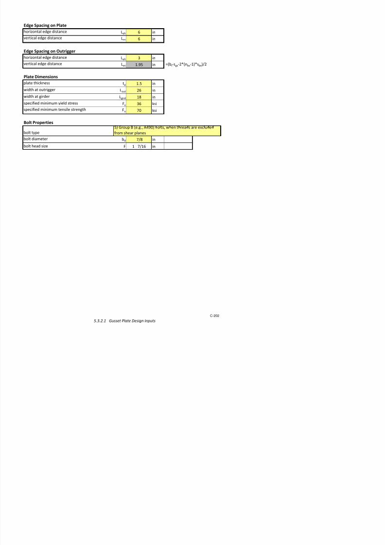
7/17/2019 Structural Design Project of Super Tall Building Chicago Spire
http://slidepdf.com/reader/full/structural-design-project-of-super-tall-building-chicago-spire 369/474
Created by: JLB 3/1/2012
Design tool to calculate the capacity of groups of headed anchor bolts in concrete according to AC 31!"0!
Ban# Color $ey: %ser nput
Location Constant/&re'ious Calc(
Bea) Calc/Loo#up
Anchor configuration acceptable* +es &asses Chec#
,o -ails Chec#
Applied Loads
factored tensile force applied to anchor or group of
anchors,ua .2 #ips
factored shear force applied to a single anchor or
group of anchorsua 12 #ips
location of factored tensile force cg, 1!( in )easured fro) center of loest bolt ro
Bolt and Layout Properties
bolt type
nu)ber of colu)ns of bolts per side nbh 2
nu)ber of ros of bolts nb'
nu)ber of anchors in group n !
nu)ber of hoo#ed bolts nL 0 included in the total of anchors4 n
bolt dia)eter db /! in
distance fro) the inner surface of the shaft of a J"
or L"bolt to the outer tip of the J" or L"bolteh 3 in
'ertical bolt spacing sb' . in
hori5ontal bolt spacing sbh in
effecti'e e)bed)ent depth of anchor hef 12 in
'ertical centroid of bolt group cgb 10( in )easured fro) center of loest bolt ro
Concrete Properties
specified co)pressi'e strength of concrete f6c 1000 psi
Results
Design 7ension 8trength 9,n 12 #ips .;
Design 8hear 8trength 9n 1.0 #ips .;
8hear"7ension nteraction 0(0. <,ua/9,n=/3
><ua/9n=/3
Anchor configuration acceptable* +es full strength in tension per)itted if ua ?@ 0(29n
full strength in shear per)itted if ,ua ?@ 0(29,n
shear"tension interaction to be ?@ 1 otherise
5.1.5.2 Concrete Anchor Bolt Design
3
ech( -loor
adial irder
= roup B <e(g(4 A0= bolts4 hen threads are eEcluded fro) shear planes
+es

7/17/2019 Structural Design Project of Super Tall Building Chicago Spire
http://slidepdf.com/reader/full/structural-design-project-of-super-tall-building-chicago-spire 370/474
Design Requirements for ensile Loading !AC" #1$%&$ D.5'
Design (trength
,o)inal 7ension 8trength ,n 1.4.1: lbs ini)u) of ,sa 4 ,cbg4 and ,png
8trength reduction factor 9 0(.0 According to D((
Design 7ension 8trength 9,n 12(! #ips
D.5.1 (teel (trength of Anchor in ension
effecti'e cross"sectional area of single anchor in
tensionAse4, 0(22: in
2
@ <F/=<db"0(.3/nt=2
nu)ber of anchors in group n !
specified tensile strength of anchor steel -u 124000 psinot greater than s)aller of 1(G-y
and 124000
anchor steel yield strength -y 1134000 psi fro) 7able J3(2
,o)inal strength of group of anchors in tension ,sa 22:4002 lbs @ nGAse4,G-u H <D"3=
D.5.2 Concrete Brea)out (trength of Anchor
proIected concrete failure area of a single anchor
if not li)ited by edge distance or spacingA,co 142: in
2@ Ghef
2 H
<D":=
proIected concrete failure area of a group of
anchorsA,c 242!0 in
2eual to nA,co for anchors spaced K@
3Ghef apart
coefficient for basic concrete brea#out strength in
tension#c 2 2 for cast"on4 1. for post installed
)odification factor reflecting the reduced
)echanical properties of lighteight concrete 1(0 -or nor)al eight concrete
basic concrete brea#out strength in tension of a
single anchor in crac#ed concrete,b 11!40 lbs @ #cGG<f6c=
1/2Ghef
1( H <D".=
distance beteen resultant tension load on a
group of anchors and the centroid of the group of
anchors
e6, ! in
)od( -actor for anchor groups loaded
eccentrically in tensionMec4, 0(. @ <1>2Ge6,/3Ghef =
"1 H <D"=
)od -actor for edge effects of anchors loaded in

7/17/2019 Structural Design Project of Super Tall Building Chicago Spire
http://slidepdf.com/reader/full/structural-design-project-of-super-tall-building-chicago-spire 371/474
)od( -actor for edge effects of anchors loaded in
tensionMed4, 1(0 ,o edge effects hen far fro) edge
)od( -actor for anchors located in region ith no
crac#ing at ser'ice load le'elsMc4, 1(2 for cast"in anchors
D.5.# Pullout (trength of Anchor in ension
)odification factor for an anchor located in a
egion of concrete )e)ber here analysis
indicates no crac#ing at ser'ice load le'els
Mc4& 1(Mc4& @ 1(0 here analysis indicates
crac#ing at ser'ice load le'els
pullout strength in tension of a single headed stud
or headed bolt,ph .413. lb @ !GAbrgGf6c H <D"1=
no)inal pullout strength of a single headed stud
or headed bolt in tension,pnh 10412 lb @ Mc4&G,&h H <D"1=
pullout strength in tension of a single hoo#ed bolt ,pL 234:2 lb@ 0(Gf6cehGdb H <D"1:= for
3Gdb?@eGh?@(Gdb
no)inal pullout strength of a single hoo#ed bolt intension
,pnL3340. lb
@ Mc4&G,&L H <D"1=
net bearing area of the head of stud4 anchor bolt4
or headed defor)ed barAbrg 0(:. in
2 @ <31/2
/2=-2"<F/=db
2H Area of heE
head )inus area of bolt shaft
no)inal pullout strength of a group of anchors ,png !1433 lb @ ,pnlGnL>,pnhG<n"nL=
D.5.* Concrete (ide%+ace Blo,out strength of a -eaded Anchor in ension
,ot applicable for large edge distances

7/17/2019 Structural Design Project of Super Tall Building Chicago Spire
http://slidepdf.com/reader/full/structural-design-project-of-super-tall-building-chicago-spire 372/474
Design Requirements for (hear Loading !AC" #1$%&$ D.'
Design (trength
,o)inal 8hear 8trength n 224002 lbs @ ,<sa4cpg=
8trength reduction factor 9 0(. According to D((
Design 8hear 8trength 9n 1.0 #ips
D..1 (teel (trength of Anchor in (hear
nu)ber of colu)ns of bolts nbh 2
nu)ber of ros of bolts nb'
nu)ber of anchors in group n !
bolt dia)eter db 0(3 in'ertical bolt spacing sb' .(00 in2
hori5ontal bolt spacing sbh (00 in2
anchor steel yield strength -y !4000 psi fro) 7able J3(2
specified tensile strength of anchor steel -u 124000psi
not greater than s)aller of 1(G-y
and 124000
effect( N"sect( Area of single bolt Ase4 0(23 in2
@ <F/=<db"0(.3/nt=2
,o)inal strength in shear sa 224002 lbs @ nGAse4G-u
D..2 Concrete Brea)out (trength of Anchor in (hear
D..# Concrete Pryout (trength of Anchor in (hear
,o)inal pryout strength <group= cpg 3432 lbs @ #pcG,cbg H <D"31=
coefficient for pryout strength #cp 2(00@ 1(0 for hef ? 2(in4 2(0 for
hef K@ 2(in
O-or anchors far fro) the edge4 D((2(usually ill not go'ern( -or these
cases4 D((1 and D((3 often go'ernO

7/17/2019 Structural Design Project of Super Tall Building Chicago Spire
http://slidepdf.com/reader/full/structural-design-project-of-super-tall-building-chicago-spire 373/474
5.2 Base of Mega-Column Connection
5.2.1 Mega-Column to Caisson Connection 190
5.2.2 Caisson Cap Moment Reinforcement 194
Mega-Columns
Shaft Columns
3 Column Node Beam
Caissons
Caisson Cap

7/17/2019 Structural Design Project of Super Tall Building Chicago Spire
http://slidepdf.com/reader/full/structural-design-project-of-super-tall-building-chicago-spire 374/474
Created by: JL 4/28/2012
Color Key User Input
Constant/Previous Calc
Calc/Loo!up
"es Passes C#ec!
$o %ails C#ec!
Loads Coming Down from Mega-Column
Pu &'(8&2 !ips
)u 2'(488 !ips
*u+, 28(040 !ips
*u+y 2-(10- !ips
.u+, '(48 !ips+t
.u+y +2(02 !ip+t
3ll values ro .idas 5en .odel
dc ' in
b+.C ' in
%y+.C &0 !si
6s+.C 2(000 !si
d ' in
t 40 in
t7 40 in
b 420 in
>uilt Up 1)ype o ection used
?eb )#ic!ness
@verall ;ept# o >ea
%lan<e )#ic!ness
.oent+y
.odulus o 6lasticity
;ept# o .e<a+Coluns
%lan<e ?idt#
"ield tren<t# o teel
)#is preads#eet calculates t#e capacities and c#ec!s t#e connection ro t#e botto o t#e .e<a+Colunto Caissons )#e spreads#eet <oes t#rou<# bearin< c#ec!s and local buc!lin< ro bearin<( as 7ell as 7eld
c#ec!s in tension )#is spreads#eet ollo7s t#e <uidelines outlined in 3IC teel Construction .anuel 1't#
ed C#apter 1
5.2.1 Mega-Column to Caisson Connection
Location
Connection
>t o .e<a+Coluns
)yp Connection
Mega-Column Steel Properties
3 Column Node eam Properties
%lan<e ?idt#
Copression
)ension
#ear+, direction
#ear+y+direction
.oent+,
' Colu4n $ode >ea4
:#a0t Colu4n
.e<a+
Colu4n
Load

7/17/2019 Structural Design Project of Super Tall Building Chicago Spire
http://slidepdf.com/reader/full/structural-design-project-of-super-tall-building-chicago-spire 375/474
%y &0 !si
6s 2(000 !si
<
"ield tren<t# o teel
.odulus o 6lasticity
dsc '0 in
t+sc 40 in
t7+sc 40 in
b+sc 200 in
%y+sc &0 !si
6s+sc 2(000 !si
Lsc 40 t
Concrete Copressive tren<t# =c 14 !si
S!ear Capacit" of 3 Column Node eam
PJP
7t '-& in
%6AA 80 !si
L7 -20 in B b 2
37 810 in2 B 7t 7l
3net 4'2 in2
B t7; n;ts D 52+1
?eld #ear eduction %actor Es+7 0-&
>ase .at #ear eduction %actor Es+>. 100
En+7 2(10 !ips B Es+700%e,,37 D )able J2&
En+>. 12(0 !ips B Es+>.00 3net%yD 52+1
)U 10(&28 !ips
=C 14 !si
Fc 14& pc
6c (&'' !si B 7c1&
G=cH0&
D I'+'
%U & !si
ds 0-& in
3sc 044 in2
B db2/4
n 28-2 !ips B inG0&3sc=c6c ( 3sc%uH D I'+'
$eed #ear tuds
)ensile tren<t# o #ear tud
)ype o ection Used >uilt Up 2
3rea or #ear o ' Colun $ode
Concrete Copress tren<t#
;ensity o Concrete
.odulus o 6lasticity o Conc
@verall ;ept# o >ea
%lan<e )#ic!ness
?eb )#ic!ness
%lan<e ?idt#
"ield tren<t# o teel
.odulus o 6lasticity
)ype o ?eld
?eld 6ective )#roat )#ic!ness
#ear tren<t# o ?eld
#ear tr o >ase .aterial
C#ec! .in En *U9
6lectrode tren<t# o ?eld
?eld len<t#
6ective ?eld 3rea
Len<t# o Colun
S!aft Column Properties
eMuired eainin< )ensile tr
tud ;iaeter
3rea o tud
tren<t# o #ear tud
:#a0t Colu4n :ection

7/17/2019 Structural Design Project of Super Tall Building Chicago Spire
http://slidepdf.com/reader/full/structural-design-project-of-super-tall-building-chicago-spire 376/474
&2& B )u/ n
nro7 10
nuber o s#ear studs reMuired
nuber o ro7s o s#ear studs
Eb 0-&
3pb 1(2in
2 B ;
.Cb
+.C
n 11(40 !ips B 183pb%y D J-+1
Ebn 8-(480 !ips B Ebn
E 10
, 144 in B L12 /2! -00 in
$ ' in B b+.C
En 42(00 !ips B G&! $H%yt7E D J10+2
E 0-&, 14400 in B L12 /2
$ '00 in B b+.C
n 1(&' !ips
En 4(240 !ips
E 0-&
3pb -20 in2
B ;.Cb+.C
n 4(800 !ips B 183pb%y D J-+1
En 48(00 !ips B Ebn
E 100
, 100 in
! -00 in
eduction %actor
Location o orce ro ed<e
;ist ro lan<e to 7eb 7eld
#e$ Local %ielding at 3 Column Node &'op( &)*SC +.1,.1(
%actored ;esi<n tren<t#
>earin< Len<t#
eduction %actor
ProNected >earin< 3rea$oinal tren<t#
;esi<n tren<t#
#e$ local %ielding at ottom from S!aft Column &)*SC +.1,.1(
En Pu/GO stieners 1H 9
En Pn/GO stieners 1H 9
"6
"6
#e$ Crippling at 'op from Mega-Columns &)*SC +.1,.3(
eduction %actorLocation o %orce ro 6d<e
>earin< Len<t#
$oinal tren<t#
%actored ;esi<n tren<t#
B E080t72G1'G$/dHGt7/t H
1&H
GG6%yt H/t7H0&
D J10+4
"6
eduction %actor
ProNected >earin< 3rea
$oinal tren<t#
;esi<n tren<t#
En Pu9
C!ec earing Strengt! at ottom from S!aft Column &)*SC +(
eduction %actor
Location o orce ro ed<e;ist ro lan<e to 7eb 7eld
En Pu9 "6
earing Strengt! at 'op of 3 Column Node eam &'op( &)*SC +(

7/17/2019 Structural Design Project of Super Tall Building Chicago Spire
http://slidepdf.com/reader/full/structural-design-project-of-super-tall-building-chicago-spire 377/474
$ 200 in B b+.C
En ''(000 !ips B G&! $H%yt7E D J10+2
>earin< Len<t#
%actored ;esi<n tren<t#
E 0-&
, 20
$ 0 in B b+.C
n 1(&' !ips
En 4(240 !ips
C!ec S!aft Column #elds in 'ension
P 144 in
L7 144 in
7t 2&0 in
%7 -0 !si
37 '0 in2
B L7
E 080
En 12(0 !ips B E00%6AA37 D )able J2&
eMuired )ension %orce )u 11(-44 !ips
*Compare Against half of the tension since there are !o "haft Columns"
C!ecout S!aft Column for Pullout and 'ension /orces
3 2-2 in2
eduction %actor E 0
Pn 1'(00 !ips B %y3 D ;2+1EtPn 12(240 !ips
eMuired )ensile tren<t# )u 11(-44 !ips
*Compare Against half of the tension since there are !o "haft Columns"
Determine t!e 0m$edment Lengt! of Column in S!aft
d ' in B ;sc
%y &0 !si
=c 14 !si
l -1 in B d /G2&G= H0&
H D 3CI '18 C#apter ;
"6
$oinal tren<t# o ?eld
6ective 3rea o ?eld
tren<t# Capacity o ?eld
eduction %actor
"6
#e$ Crippling at ottom from S!aft Column &)*SC +.1,.3(
En Pn/GO stieners 1H 9 "6
3rea o teel #ape
)ensile tren<t#
B E040t72G1'G$/dHGt7/t H
1&H
GG6%yt H/t7H0&
D J10+4
C#ec! En )u
)#roat )#ic!ness
eduction %actor
Location o %orce ro 6d<e
>earin< Len<t#
$oinal tren<t#
%actored ;esi<n tren<t#
;iaeter o Colun
"ield tren<t# o #at Colun
Concrete Copressive tren<t#
6bedent Len<t#
C#ec! EPn )u
%actored )ensile tren<t#
Pereter o Colun
Len<t# o ?eld

7/17/2019 Structural Design Project of Super Tall Building Chicago Spire
http://slidepdf.com/reader/full/structural-design-project-of-super-tall-building-chicago-spire 378/474
ld -1 in B y db/G2& G cH H D 3CI '18 + C#apter ;
ld '4 t
"6I C 6 b d L # @! 9
6bedent Len<t#
6bedent Len<t#
5.2.2 Caisson Cap Moment Reinforcement JL 4/29/2012
User Input
Constant/Previous Calc.
Calc/Lookup
Moment Coming Down from Mega-Column Yes Passes Check
Moent ! " Mu!# $%4&' kips!(t )o *ails Check
Moent ! " Mu!# 41%&$2 kips!in
Moent ! Y Mu!+ 2%902 kips!(t
Moent ! Y Mu!+ $4%&24 kips!in
Caisson Cap Dimensions and Properties
, 1& (t
L 2& (th 22 (t
(-c 14 ksi
c 10 l,/(t$
c 21$%24 ksi %0003(-c0.
( +r '0 ksi
s 29%000 ksi
1&
5,ar 2.2 in
6,ar 4.00 in2
Calculate the Required Number of ars !long the " Direction #$hort ars%
5# 24 in 7 ! '8 ! $8 ! 5,/2
0.9
6sr!re: $.0 in2 3 ;ee e:uation at the en5 o( sheet
4/$36sr!re: 4.0 in2 4/$ 3 6s!re:
i 1%9& in2 <$3<(-c=
0.3L35#=/( +
Bi5th o( Caisson
Len?th o( Caisson7ei?ht o( Caisson
Concrete Copressive ;tren?th
ensit+ o( Concrete
Mo5ulus o( lasticit+ o( Concrete
@e,ar Yiel5 ;tren?th
Mo5ulus o( lasticit+ o( ;teel
Aar ;iDe o( re,ar
iaeter o( re,ar
6rea o( @ein(orcin? ,ar
Create5 A+E
Calculates the re:uire5 rein(orcin? area ,ase5 on the loa5s ?enerate5 (ro Mi5as Fen. Ghe area o(
steel is calculate5 usin? the Bhitne+ ;tress Alock (or concrete an5 is then checke5 a?ainst iniu
steel e:uations (oun5 in C@;I 200& esi?n Fui5e.
Location
Connection
Aotto o( Me?a!Colun
G+p. Connection
epth to centroi5 o( re,ar
@e5uction *actor (or Moent
@e:uire5 6rea o( ;teel
Color e+
;ha(t Colun
Me?a!
Colun
Loa5$ Colun
)o5e Aea
Caisson
Cap

7/17/2019 Structural Design Project of Super Tall Building Chicago Spire
http://slidepdf.com/reader/full/structural-design-project-of-super-tall-building-chicago-spire 379/474
ii 2&4%$$' in2 <2003L35#=/( +
iii 1'0 in2
0.001&3L37
6sr in Calculations
Calculate the Required Number of ars !long the & direction #'ong ars%
5+ 22 in 7 ! '8 ! $8 ! 5, !5,/2
0.9
6sr!re: 2.' 33 ;ee e:uation at en5 o( sheet
4/$36sr!re: $.42 in2
4/$ 3 6s!re:
i 10%1'& in2
<$3<(-c=0.
3,35+=/( +
ii 2&1%&0& in2
<2003,35+=/( +
iii 10$ in2
0.001&3,37
6sr in 10$ in2
Min<I%ii%iii=
n, 2' 6s!in/6s
s+ $.0 in2
<, ! n,35,= / <5, >1=
3 :uation (or 6s!re: (or Moent a,out " a#is <;hort Aars=
33 :uation (or 6s!re: (or Moent a,out the Y a#is < Lon? Aars=
;pacin? H Min< 5, or 18=
epth to centrio5 o( re,ar in Y
@e5uction *actor (or Moent
@e:uire5 6rea o( ;teel
Controllin? 6s!in
@e:uire5 )u,er o( Aars
;pacin?
6sr in Calculations
Y;
=( ∗ ∗
= K ( ∗ ∗
=2 − 4 ∗ ( ∗ fy
2
2 ∗ 0.85 ∗ f c ∗ )
∗
Mu#
2 ∗ ( ∗ fy2
2 ∗ 0.85 ∗ f c ∗ )
=( ∗ ∗
= K ( ∗ ∗
=2 − 4 ∗ (
∗ fy2
2 ∗ 0.85 ∗ f c ∗ ) ∗ Mu+
2 ∗ ( ∗ fy2
2 ∗ 0.85 ∗ f c ∗ )

7/17/2019 Structural Design Project of Super Tall Building Chicago Spire
http://slidepdf.com/reader/full/structural-design-project-of-super-tall-building-chicago-spire 380/474
5.3 Outrigger Connections
5.3.1 Bottom of Outrigger to Column Connection 197
5.3.2 Top of Outrigger to Core 199
Outriggers

7/17/2019 Structural Design Project of Super Tall Building Chicago Spire
http://slidepdf.com/reader/full/structural-design-project-of-super-tall-building-chicago-spire 381/474
5.3.1 Bottom of Outrigger to Column Connection
Bank: 4 Color Key: User Input
Location: Typical Column Constant/Previous Calc.
Calc/Lookup
Yes Passes Check
o !ails Check
Outrigger to Column Connection
Design Adequate?
"ertical Loa# at Connection $u %&'' Kips !rom (i#as )en (o#el
Girder Properties
)ir#er section *section +4 , -'
Beam lan0e 1i#th 2 +-.3 in
Beam lan0e thickness t 4.3+ in
Beam 1e2 thickness t1 .'- in
Beam #epth # %%.4 in
Beam k+ K+ %.-& in
Plate Properties
Plate thickness tp .&' in
Plate len0th Lp %.' in
Plate 1i#th 1p %'.' in
plate yiel#in0 stren0th !y &' ksi
PASS
Create# 2y: ;? 4/%+/+%
?esi0n tool or the outri00er truss to the e,terior columns usin0 1el#s. The ra#ial 0ir#er 1ill 2e #esi0ne# usin0
the moment resistin0 0ir#er connection sprea#sheet.
Column
@utri00er
)ir#er
Plates

7/17/2019 Structural Design Project of Super Tall Building Chicago Spire
http://slidepdf.com/reader/full/structural-design-project-of-super-tall-building-chicago-spire 382/474
plate yiel#in0 stren0th !y &' ksi
plate ultimate stren0th !u & ksi
Plate Sear "upture
et area o shear plane nv 3+.'' in% 7 ALp<An8#2+/DD8tp
Plate shear rupture stren0th 6$n %% kips 7 A'.-&8'.8!u8nvD 9 I5C ;4<4
6$n ≥ $u= Y>5
Bloc# Sear "upture
)ross area o shear plane 0v -3.% in% 7 Lp8(IAtpEt1D
et area o tension plane nt +.4 in% 7 A1p<A#2+/DD8(IAtpEt1D
Block shear rupture stren0th Amin 6$nD 6$n &&& kips 7 '.-&A'.8!u8nv!u8ntD 9 I5C ;4<&
6$n 4-3 kips 7 '.-&A'.8!y80v!u8ntD 9 I5C ;4<&
(I 6$n ≥ $u= Y>5
$eld% &illet $eld
>lectro#e classiication num2er !>FF -' ksi
5iGe o 1el# siGe % in
um2er o *el#s Type + %
Throat thickness 1t +.4+4 in 7 '.-'-8siGe
Len0th o the 1el# type + L1 %&.'' in one si#e o plate
*el# + stren0th 6$n+ %%%- kips 7 '.-&8te8L18'.8!>FF 9 I5C ;%<4
um2er o 1el#s type % %
Len0th o the 1el# type % L1 +'.'' in
*el# % stren0th 6$n% 3+ Kips 7 '.-&8te8L18'.8!>FF 9 I5C ;%<4
Total 1el# stren0th 6$n ++ 7 6$n+6$n%
6$n ≥ $u= Y>5

7/17/2019 Structural Design Project of Super Tall Building Chicago Spire
http://slidepdf.com/reader/full/structural-design-project-of-super-tall-building-chicago-spire 383/474
5.3.2
Top of Outrigger to Core
5.3.2.1
Gusset Plate Design Inputs 200
5.3.2.2 Single Bolt Shear Capacity 203
5.3.2.3 Bolt and Plate Checks or !utrigger Connection 20"
5.3.2." Bolt and Plate Checks or Girder Connection 20#
5.3.2.5
$eld Design or Gusset Plate to %&'edded Steel (ra&e 210
5.3.2.) Steel (ra&e %&'edded in Concrete Core Design 211
5.3.2.# %&'edded Steel (ra&e Shear Stud Spacing 21#
$eld
Gusset Plate
!n %ach Side
*adial Girder

7/17/2019 Structural Design Project of Super Tall Building Chicago Spire
http://slidepdf.com/reader/full/structural-design-project-of-super-tall-building-chicago-spire 384/474
!utrigger
5.3.2.1 Gusset Plate Design Inputs
Input dimensions for gusset plate, outrigger member, column member, floor girder, and bolts
Column Section
selected section W33 x 152
specified minimum yield stress Fy 50 ksi
specified minimum tensile strength Fu 5 ksi
!eb thickness t! 0"35 in
flange thicknesstf 0"#55 in
depth d 33"5 in
!idth bf 11" in
distance from !eb center to line of flange toe of
filletk1 1"125 in
Girder Section
selected section W1$ x %30
specified minimum yield stress Fy 50 ksi
specified minimum tensile strength Fu 5 ksi
!eb thickness t! 3"0% in
flange thickness tf $"&1 in
depth d 22"$ in
!idth bf 1%"& in
distance from !eb center to line of flange toe offillet
k1 2"%5 in
re'uired loads (u 22$ kips
load per gusset plate (u)2 112 kips

7/17/2019 Structural Design Project of Super Tall Building Chicago Spire
http://slidepdf.com/reader/full/structural-design-project-of-super-tall-building-chicago-spire 385/474
number of hori*ontal bolt groups ngh 2
min" spacing bet!een hori*ontal bolt groups % in + 2k1-F
selected spacing bet!een hori*ontal bolt groups sg.
# in
spacing check /es
number of ro!s of bolts per group nb. 1
.ertical bolt spacing sb. 0 in
number of columns of bolts nbh 3
hori*ontal bolt spacing sbh 3 in
Edge Spacing on Platehori*ontal edge distance eh 3 in
.ertical edge distance e. 3 in
Edge Spacing on Girder
hori*ontal edge distance eh $ in
.ertical edge distance e. $"&5 in + bf sg.2nb.1sb.)2
Outrigger Section
selected section W1$ x %30
specified minimum yield stress Fy 50 ksi
specified minimum tensile strength Fu 5 ksi
!eb thickness t! 3"0% in
flange thickness tf $"52 in
depth d 22"$ in
!idth bf 1%"& in
distance from !eb center to line of flange toe of
filletk1 2"%5 in
number of hori*ontal bolt groups ng. 2
min" spacing bet!een hori*ontal bolt groups % in + 2k1-F
selected spacing bet!een hori*ontal bolt groups sg. # in
spacing check /es
number of ro!s of bolts per group nb. 2
ti l b lt i

7/17/2019 Structural Design Project of Super Tall Building Chicago Spire
http://slidepdf.com/reader/full/structural-design-project-of-super-tall-building-chicago-spire 386/474
.ertical bolt spacing sb. 3 in
b f l f b lt
Edge Spacing on Plate
hori*ontal edge distance eh in
.ertical edge distance e. in
Edge Spacing on Outrigger
hori*ontal edge distance eh 3 in
.ertical edge distance e. 1"&5 in +bf sg.2nb.1sb.)2
Plate Dimensions
plate thicknesstp 1"5 in
!idth at outrigger out 2 in
!idth at girder gird 1# in
specified minimum yield stress Fy 3 ksi
specified minimum tensile strength Fu %0 ksi
Bolt Properties
bolt type
bolt diameter bd %)# in
bolt head si*e F 1 %)1 in
5 roup 6 e"g", 7$&0 o ts, ! en t rea s are exc u efrom shear planes
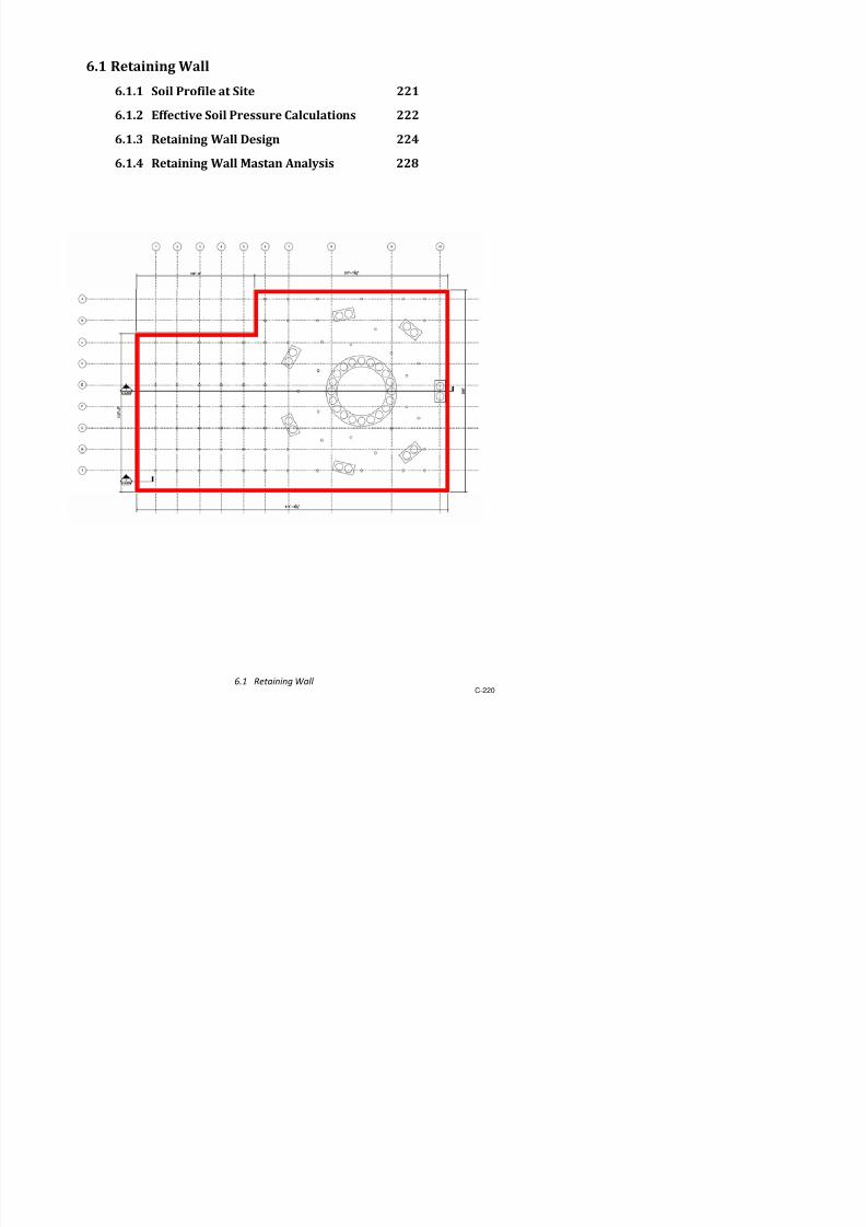
7/17/2019 Structural Design Project of Super Tall Building Chicago Spire
http://slidepdf.com/reader/full/structural-design-project-of-super-tall-building-chicago-spire 387/474
5.3.2.2 Single Bolt Shear Capacit
8etermine if the bolts slip and fail in shear
a.ailable slip resistance 9(n 1" kips 9:8uhf ;bns
9 1"00
bolt diameter db %)# in
mean slip coefficient : 0"30 for <lass 7 surfaces
pretension multiplier 8u 1"13
factor for fillersh
f 1 for one filler bt!n connected partsmin" fastener tension ;b $& kips ;able =3"1
number of slip planes
re'uired to permit the
connection to slip
ns 1
a.ailable shear strength 9(n 3%"& kips 9>n7b =31
reduction factor 9 0"%5
nominal shear stress >n #$ ksi
nominal unthreaded body
area of bolt 7b 0"01 in2
?da2)$
shear strength greater than slip resistance@ /es

7/17/2019 Structural Design Project of Super Tall Building Chicago Spire
http://slidepdf.com/reader/full/structural-design-project-of-super-tall-building-chicago-spire 388/474
5.3.2.3 Bolt and Plate Chec!s "or Outrigger Connection
Strength Chec!
re'uired strength 4u 1,0&5 kips
design strength 9(n 1,212 kips
does it pass@ /es
Bolt Chec!
min" A of bolts nmin 2& bolts min A for bolt shear
actual number of bolts nb 32 bolts
does it pass@ /es
Plate Properties
plate thickness tp 1"5 in
!idth at outrigger out 2 in
specified minimum yield stress Fy 3 ksi
specified minimum tensile strength Fu %0 ksi
hori*ontal edge distance eh in
.ertical edge distance e. in
Bolt Group Properties
bolt diameter db %)# in
number of hori*ontal bolt groups ngh 2
selected spacing bet!een hori*ontal bolt gr sg. # in
number of ro!s of bolts per group nb. 2
.ertical bolt spacing sb. 3 in
number of columns of bolts nbh #
hori*ontal bolt spacing sbh $ in
Outrigger Properties
specified minimum yield stress F 50 ksi
<hecking failure modes for bolts and plate at the connection bet!een gusset plate and outrigger
connection

7/17/2019 Structural Design Project of Super Tall Building Chicago Spire
http://slidepdf.com/reader/full/structural-design-project-of-super-tall-building-chicago-spire 389/474
specified minimum yield stress Fy 50 ksi
Gross #rea o" Plate
gross area 7g 3&"0 in2
+ min 7!, 7gp
Whitmore Bection !idth l ! $"3 in
Whitmore area 7! &"5 in2
+ l !tp
gross area from plate dimensions 7gp 3&"0 in + outtp
Bolt Shear Strength
design strength 9(n 1,212 kips + 9Fn.7bnb =31
$ensile %ielding o" Gusset Platedesign strength 9(n 1,2$ kips + 9Fy7g =$1
9 0"&0
specified minimum yield stress Fy 3 ksi
gross area 7g 3&"0 in
$ensile &upture o" Gusset Plate
design strength 9(n 1,%52 kips + 9Fu7e =$2
9 0"%5
specified minimum tensile strength Fu %0 ksi
effecti.e net area 7e 33"$ in2
7nC 831
shear lag factor C 1"0 ;able 83"1
net area 7n 33"$ in
Bloc! Shear &upture o" Gusset Plate
a.ailable strength 9(n 1,&2 kips 9CbsFu7nt-90"0minFu7n.,Fy7g.D=$5
9 0"%5
reduction coefficient Cbs 1"0
gross area subEect to shear 7g. 51"0 in2
+ e.-nbh1sbhGtp
net area subEect to shear 7n. 3&"# in2
+ eh-nbh1sbhnbh0"5da-"125Gtp
net area subEect to tension 7nt 1"5 in2
+ 2e.0"5da-0"125Gtp
Bloc! Shear &upture o" 'lange
a.ailable strength 9(n 3,0 kips 9CbsFu7nt-90"0minFu7n.,Fy7g.D =$5
9 0"%5

7/17/2019 Structural Design Project of Super Tall Building Chicago Spire
http://slidepdf.com/reader/full/structural-design-project-of-super-tall-building-chicago-spire 390/474
reduction coefficient Cbs 1"0
Bolt Bearing on Gusset Plate
a.ailable bearing strength 9(n 3,1# kips + 9tpFuHIJ 1"51l c,nb3"0da D =3b
9 0"%5
clear distance, in dir" of force, bet!een
edge of hole and edge of materiall c edge 5"5 in
clear distance, in dir" of force, bet!een
edge of hole and edge adEacent holel c int 3"1 in
J 1"51l c $0"5 in
nb3"0da #$"0 in
Bolt Bearing on 'lange
a.ailable bearing strength 9(n 1,%&# kips + 9tf FuHIJ 1"51l c,nb3"0da D =3b
9 0"%5
clear distance, in dir" of force, bet!een
edge of hole and edge of materiall c edge 2"5 in
clear distance, in dir" of force, bet!een
edge of hole and edge adEacent holel c int 3"1 in
J 1"51l c #"2 in
nb3"0da #$"0 in

7/17/2019 Structural Design Project of Super Tall Building Chicago Spire
http://slidepdf.com/reader/full/structural-design-project-of-super-tall-building-chicago-spire 391/474
5.3.2.( Bolt and Plate Chec!s "or Girder Connection
Strength Chec!
re'uired strength (u 112 kips
design strength 9(n 22% kips
does it pass@ /es
Bolt Chec!
min" A of bolts nmin 3 bolts min A for bolt shear
actual number of bolts nb bolts
does it pass@ /es
Plate Properies )"rom Inputs*
plate thickness tp 1"5 in
!idth at girder gird 1# in
specified minimum yield stress Fy 3 ksi
specified minimum tensile strength Fu %0 ksi
hori*ontal edge distance eh 3 in
.ertical edge distance e. 3 in
Bolt Group Properties
bolt diameter da %)# innumber of hori*ontal bolt groups ngh 2
selected spacing bet!een hori*ontal bolt
groups sg. # in
number of ro!s of bolts per group nb. 1
.ertical bolt spacing sb. 0 in
number of columns of bolts nbh 3
hori*ontal bolt spacing sbh 3 in
Girder Properties
specified minimum yield stress Fy 50 ksi
specified minimum tensile strength F 5 ksi
<hecking failure modes for bolts and plate at the connection bet!een gusset plate and outrigger

7/17/2019 Structural Design Project of Super Tall Building Chicago Spire
http://slidepdf.com/reader/full/structural-design-project-of-super-tall-building-chicago-spire 392/474
specified minimum tensile strength Fu 5 ksi
Gross #rea o" Plate
gross area 7g 22"$ in2
+ HI7!, 7gp
Whitmore Bection !idth l ! 1$"& in
Whitmore area 7! 22"$ in2
+ l !tp
gross area from plate dimensions 7gp 2%"0 in + outtp
Bolt Shear Strength
design strength 9(n 22% kips + 9Fn.7bnb =31
$ensile %ielding o" Gusset Platedesign strength 9(n %2 kips + 9Fy7g =$1
9 0"&0
specified minimum yield stress Fy 3 ksi
gross area 7g 22"$ in
$ensile &upture o" Gusset Plate
design strength 9(n 12%0 kips + 9Fu7e =$29 0"%5
specified minimum tensile strength Fu %0 ksi
effecti.e net area 7e 2$"2 in2
+ 7nC 831
shear lag factor C 1"0 ;able 83"1
net area 7n 2$"2 in
Bloc! Shear &upture o" Gusset Plate
a.ailable strength 9(n $$ kips + 9CbsFu7nt-90"0minFu7n.,Fy7g. D =$5
9 0"%5
reduction coefficient Cbs 1"0
gross area subEect to shear 7g. 1"5 in2
+ e.-nbh1sbhGtp
net area subEect to shear 7n. 1$"3 in2
+ eh-nbh1sbhnbh0"5da-"125Gtp
net area subEect to tension 7nt 3"# in2
+ 2e.0"5da-0"125Gtp
Bloc! Shear &upture o" 'lange
a.ailable strength 9(n 50 kips + 9CbsFu7nt-90"0minFu7n.,Fy7g. D =$5
9 0"%5
reduction coefficient C 1 0

7/17/2019 Structural Design Project of Super Tall Building Chicago Spire
http://slidepdf.com/reader/full/structural-design-project-of-super-tall-building-chicago-spire 393/474
reduction coefficient Cbs 1"0
Bolt Bearing on Gusset Plate
a.ailable bearing strength 9(n %# kips + 9tpFuHIJ 1"51l c,nb3"0da D =3b
9 0"%5
clear distance, in dir" of force, bet!een edge of
hole and edge of materiall c edge 2"5 in
clear distance, in dir" of force, bet!een edge of
hole and edge adEacent holel c int 2"1 in
J 1"51l c 10"0 in
nb3"0da 15"# in
Bolt Bearing on 'langea.ailable bearing strength 9(n 3%%0 kips + 9tf FuHIJ 1"51l c,nb3"0da D =3b
9 0"%5
clear distance, in dir" of force, bet!een edge of
hole and edge of materiall c edge $"5 in
clear distance, in dir" of force, bet!een edge of
hole and edge adEacent holel c int 2"1 in
J 1"51l c
1#"& in
nb3"0da 15"# in

7/17/2019 Structural Design Project of Super Tall Building Chicago Spire
http://slidepdf.com/reader/full/structural-design-project-of-super-tall-building-chicago-spire 394/474
5.3.2.5 +eld Design "or Gusset Plate to Em,edded Steel 'rame
8esign of !eld of gusset plates to embedded steel frame
+eld Speci"ications
Weld Bi*e 8 0"%5 inWeld Bi*e in sixteenths of inch 8 12 1)1 in +! 1
Klectrode K%0
Btrength of Weld FKLL %0 ksi ;able #3
Klectrode <oeffiencient <1 1 ;able #3
-ector #ddition o" oads
Mutrigger Force L <omponent Fx 1,02 kipsMutrigger Force / <omponent Fy 1,$&$ kips
Bhear Force > 22$ kips
et oad L <omponent Fx 1,02 kips
et oad / <omponent >-Fy 1,%1# kips
(esultant oad (u 2,3$# kips + Fx2 - >-Fy
2"5
7ngle of oad %% degrees !ith respect to .ertical
/et oad Design
Mutrigger 7ngle $3 degrees !ith respect to hori*ontal plane
ength of Weld ! &"3 in
8istance 6et!een Welds k! 25"$ in
> l f < ; bl k 0 3% k )
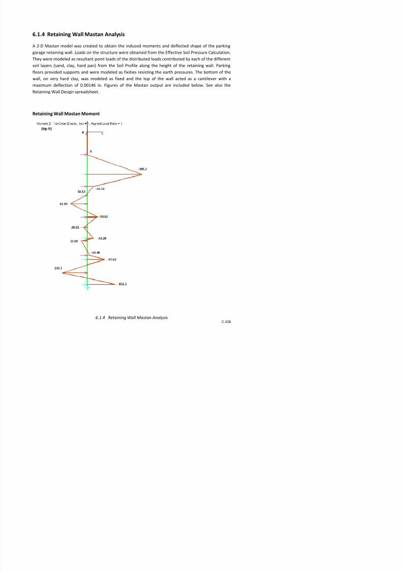
7/17/2019 Structural Design Project of Super Tall Building Chicago Spire
http://slidepdf.com/reader/full/structural-design-project-of-super-tall-building-chicago-spire 395/474
>alue for < ;ables k 0 3% +k )
5.3.2.0 Steel 'rame Em,edded in Concrete Core Design
;ensile oad 21&0 kips applied axially from points !here outrigger connects to frame
'inal Sies
6eams W1$ x 5
<olumns W33 x 152
Ficticious 6races W2$ x 103 act in compression only
ocal <oordinates
(esulting steel si*es from model of steel frame embedded inside concrete core to take load
from outriggers
• #ll mem,ers ere assumed to ,e "ull ,raced, simulating the frameOs embedment in
concrete"
•
7ll beams and columns are connected by moment connections.
•
7ll beams and columns are made of #2 Steel.
• ;he top and bottom nodes of the frame are assumed to be fixed in all directions and
rotations"

7/17/2019 Structural Design Project of Super Tall Building Chicago Spire
http://slidepdf.com/reader/full/structural-design-project-of-super-tall-building-chicago-spire 396/474
4ID#S Steel Code Chec! &esults
Chec!4em,er
/um,er
Section
/um,er.ength )"t*
5n,raced
.ength )"t*
.ateral
$orsional
Buc!ling
'actor
E""ecti6e
.ength
'actor
#7ial .oad
)!ips*
Bending
4oment
)!8"t*
Bending
4oment
)!8"t*
Chec!
Com,ined
5tili1ation
&atio
Shear
5tili1ation
&atio
5n,raced
.ength )"t*
5n,raced
.ength )"t*
.ateral$orsional
Buc!ling
'actor
E""ecti6e
.ength
'actor
/ominal#7ial
Strength
)!ips*
/ominal4oment
Capacit 1 )!8
"t*
/ominal4oment
Capacit 1 )!8
"t*
MQ 2 2 13 0 1 0"5 %& $"5$ #"%3
MQ 0"3## 0"002 0 0 1 0"5 1,&0$ 2,0& 25"5
MQ $ 2 13 0 1 0"5 %52 $%"5$ 35"#
MQ 0"513 0"012 0 0 1 0"5 2,01 2,0& 25"5
MQ % 2 13 0 1 0"5 & 3"10 #"5%MQ 0"3#1 0"002 0 0 1 0"5 1,&0$ 2,0& 25"5
MQ # 2 13 0 1 0"5 #21 2"2 32"01
MQ 0"53& 0"01 0 0 1 0"5 1,&0$ 2,0& 25"5
MQ & 2 13 0 1 0"5 %$$ &"& 3$"11
MQ 0"$## 0"011 0 0 1 0"5 2,01 2,0& 25"5
MQ 12 2 13 0 1 0"5 %# 2"1 #"5
MQ 0"3# 0"002 0 0 1 0"5 1,&0$ 2,0& 25"5
MQ 13 2 13 0 1 0"5 #2$ 5"32 3$"3&MQ 0"55 0"011 0 0 1 0"5 1,&0$ 2,0& 25"5
MQ 1$ 2 13 0 1 0"5 %51 #"53 3"15
MQ 0"$&% 0"012 0 0 1 0"5 2,01 2,0& 25"5
MQ 1% 2 13 0 1 0"5 #0 2"03 #"3
MQ 0"3# 0"002 0 0 1 0"5 1,&0$ 2,0& 25"5
MQ 1& 2 13 0 1 0"5 %52 1"0% 35"%
MQ 0"$&3 0"011 0 0 1 0"5 2,01 2,0& 25"5
MQ 22 2 13 0 1 0"5 %% 0"55 #"5%MQ 0"3#5 0"002 0 0 1 0"5 1,&0$ 2,0& 25"5
MQ 23 2 13 0 1 0"5 #2$ 0"20 3$"0
MQ 0"5$% 0"011 0 0 1 0"5 1,&0$ 2,0& 25"5
MQ 2$ 2 13 0 1 0"5 %50 0"#2 3$"&$
MQ 0"$& 0"011 0 0 1 0"5 2,01 2,0& 25"5
MQ 2% 2 13 0 1 0"5 % 0"$3 #"%1
MQ 0"3#$ 0"002 0 0 1 0"5 1,&0$ 2,0& 25"5
MQ 2# 2 13 0 1 0"5 #2$ 0"%% 33"&MQ 0"5$% 0"011 0 0 1 0"5 1,&0$ 2,0& 25"5
MQ 2& 2 13 0 1 0"5 %50 0"#& 3$"&0
MQ 0"$#& 0"011 0 0 1 0"5 2,01 2,0& 25"5
MQ 32 2 13 0 1 0"5 % 0"&0 #"#
MQ 0"3#5 0"002 0 0 1 0"5 1,&0$ 2,0& 25"5
MQ 33 2 13 0 1 0 5 #2$ 1 2# 3$ 0%

7/17/2019 Structural Design Project of Super Tall Building Chicago Spire
http://slidepdf.com/reader/full/structural-design-project-of-super-tall-building-chicago-spire 397/474
Chec!4em,er
/um,er
Section
/um,er.ength )"t*
5n,raced
.ength )"t*
.ateral
$orsional
Buc!ling
'actor
E""ecti6e
.ength
'actor
#7ial .oad
)!ips*
Bending
4oment
)!8"t*
Bending
4oment
)!8"t*
Chec!
Com,ined
5tili1ation
&atio
Shear
5tili1ation
&atio
5n,raced
.ength )"t*
5n,raced
.ength )"t*
.ateral
$orsional
Buc!ling'actor
E""ecti6e
.ength
'actor
/ominal
#7ial
Strength)!ips*
/ominal
4oment
Capacit 1 )!8"t*
/ominal
4oment
Capacit 1 )!8"t*
MQ 0"5$% 0"011 0 0 1 0"5 1,&0$ 2,0& 25"5
MQ 3& 2 13 0 1 0"5 %50 1"50 35"0$
MQ 0"$& 0"011 0 0 1 0"5 2,01 2,0& 25"5
MQ $2 2 13 0 1 0"5 % 1"3# #"%
MQ 0"3#5 0"002 0 0 1 0"5 1,&0$ 2,0& 25"5
MQ $3 2 13 0 1 0"5 #2$ 1"#1 3$"0%
MQ 0"5$% 0"011 0 0 1 0"5 1,&0$ 2,0& 25"5MQ $$ 2 13 0 1 0"5 %50 1"%% 35"10
MQ 0"$& 0"011 0 0 1 0"5 2,01 2,0& 25"5
MQ $% 2 13 0 1 0"5 % 1"5# #"
MQ 0"3#5 0"002 0 0 1 0"5 1,&0$ 2,0& 25"5
MQ $# 2 13 0 1 0"5 #2$ 2"1 3$"00
MQ 0"5$% 0"011 0 0 1 0"5 1,&0$ 2,0& 25"5
MQ $& 2 13 0 1 0"5 %50 2"30 3$"&#
MQ 0"$& 0"011 0 0 1 0"5 2,01 2,0& 25"5MQ 52 2 13 0 1 0"5 %% 1"55 #"2
MQ 0"3#5 0"002 0 0 1 0"5 1,&0$ 2,0& 25"5
MQ 53 2 13 0 1 0"5 #2$ 2"2# 3$"12
MQ 0"5$# 0"011 0 0 1 0"5 1,&0$ 2,0& 25"5
MQ 5$ 2 13 0 1 0"5 %50 2"32 35"22
MQ 0"$&1 0"011 0 0 1 0"5 2,01 2,0& 25"5
MQ 5% 2 13 0 1 0"5 %% 1"55 #"$
MQ 0"3#5 0"002 0 0 1 0"5 1,&0$ 2,0& 25"5MQ 5# 2 13 0 1 0"5 #2$ 1"% 3$"1
MQ 0"5$# 0"011 0 0 1 0"5 1,&0$ 2,0& 25"5
MQ 5& 2 13 0 1 0"5 %50 1"23 35"20
MQ 0"$&1 0"011 0 0 1 0"5 2,01 2,0& 25"5
MQ 2 2 13 0 1 0"5 %% 1"15 #"0
MQ 0"3#5 0"002 0 0 1 0"5 1,&0$ 2,0& 25"5
MQ 3 2 13 0 1 0"5 #2$ 2"0$ 33"&#
MQ 0"5$% 0"011 0 0 1 0"5 1,&0$ 2,0& 25"5MQ $ 2 13 0 1 0"5 %50 3"$2 3$"$0
MQ 0"$#& 0"011 0 0 1 0"5 2,01 2,0& 25"5
MQ % 2 13 0 1 0"5 #1 1"# #"%3
MQ 0"3#% 0"002 0 0 1 0"5 1,&0$ 2,0& 25"5
MQ # 2 13 0 1 0"5 #2 "05 35"2
MQ 0 55 0 011 0 0 1 0 5 1 &0$ 2 0& 25 5

7/17/2019 Structural Design Project of Super Tall Building Chicago Spire
http://slidepdf.com/reader/full/structural-design-project-of-super-tall-building-chicago-spire 398/474
Chec!4em,er
/um,er
Section
/um,er.ength )"t*
5n,raced
.ength )"t*
.ateral
$orsional
Buc!ling
'actor
E""ecti6e
.ength
'actor
#7ial .oad
)!ips*
Bending
4oment
)!8"t*
Bending
4oment
)!8"t*
Chec!
Com,ined
5tili1ation
&atio
Shear
5tili1ation
&atio
5n,raced
.ength )"t*
5n,raced
.ength )"t*
.ateral
$orsional
Buc!ling'actor
E""ecti6e
.ength
'actor
/ominal
#7ial
Strength)!ips*
/ominal
4oment
Capacit 1 )!8"t*
/ominal
4oment
Capacit 1 )!8"t*
MQ &2 1 1"$5% 0 1 0"5 1#2 $5"# 0"23
MQ 0"01& 0 0 0 1 0"5 #,#20 5,550 255
MQ &3 1 1"$5% 0 1 0"5 1#2 $5"5 0"32
MQ 0"01& 0 0 0 1 0"5 #,#20 5,550 255
MQ &$ 1 1"$5% 0 1 0"5 1#2 $5"# 1"1&
MQ 0"01& 0 0 0 1 0"5 #,#20 5,550 255
MQ &5 1 1"$5% 0 1 0"5 1#3 $5"20 0"5&MQ 0"01& 0 0 0 1 0"5 #,#20 5,550 255
MQ & 1 1"5#3$ 0 1 0"5 1#3 $&"5% $"55
MQ 0"021 0 0 0 1 0"5 #,#20 5,550 255
MQ &% 1 1"$5% 0 1 0"5 1#0 $$" $"30
MQ 0"02 0 0 0 1 0"5 #,#20 5,550 255
MQ &# 1 1"$5% 0 1 0"5 1#2 $%"$5 2"1$
MQ 0"02 0 0 0 1 0"5 #,#20 5,550 255
MQ && 1 1"$5% 0 1 0"5 1#2 $%"01 1"25MQ 0"01& 0 0 0 1 0"5 #,#20 5,550 255
MQ 100 1 1"$5% 0 1 0"5 1#2 $$"%5 0"%
MQ 0"01& 0 0 0 1 0"5 #,#20 5,550 255
MQ 101 1 1"$5% 0 1 0"5 1#2 $3"&3 0"%
MQ 0"01& 0 0 0 1 0"5 #,#20 5,550 255
MQ 102 1 1"$5% 0 1 0"5 1#2 $$"## 0"33
MQ 0"01& 0 0 0 1 0"5 #,#20 5,550 255
MQ 103 1 1"$5% 0 1 0"5 1#2 $5"1# 0"0MQ 0"01# 0 0 0 1 0"5 #,#20 5,550 255
MQ 10$ 1 1"$5% 0 1 0"5 3,2&5 2"32 0"&3
MQ 0"3%$ 0 0 0 1 0"5 #,#20 5,550 255
MQ 105 1 1"$5% 0 1 0"5 3,2&5 2"2% 1"11
MQ 0"3%$ 0 0 0 1 0"5 #,#20 5,550 255
MQ 10 1 1"$5% 0 1 0"5 3,2&5 2"12 1"11
MQ 0"3%$ 0 0 0 1 0"5 #,#20 5,550 255
MQ 10% 1 1"$5% 0 1 0"5 3,2&5 2"1& 1"1$MQ 0"3%$ 0 0 0 1 0"5 #,#20 5,550 255
MQ 10# 1 1"$5% 0 1 0"5 3,2&$ 2"$3 1"31
MQ 0"3%$ 0 0 0 1 0"5 #,#20 5,550 255
MQ 10& 1 1"$5% 0 1 0"5 3,2&3 3"2 10"3$
MQ 0"3%% 0 0 0 1 0"5 #,#20 5,550 255
MQ 110 1 1 51%2 0 1 0 5 3 2&1 % 33 5% 3%

7/17/2019 Structural Design Project of Super Tall Building Chicago Spire
http://slidepdf.com/reader/full/structural-design-project-of-super-tall-building-chicago-spire 399/474
Chec!4em,er
/um,er
Section
/um,er.ength )"t*
5n,raced
.ength )"t*
.ateral
$orsional
Buc!ling
'actor
E""ecti6e
.ength
'actor
#7ial .oad
)!ips*
Bending
4oment
)!8"t*
Bending
4oment
)!8"t*
Chec!
Com,ined
5tili1ation
&atio
Shear
5tili1ation
&atio
5n,raced
.ength )"t*
5n,raced
.ength )"t*
.ateral
$orsional
Buc!ling'actor
E""ecti6e
.ength
'actor
/ominal
#7ial
Strength)!ips*
/ominal
4oment
Capacit 1 )!8"t*
/ominal
4oment
Capacit 1 )!8"t*
MQ 0"01 0"&## 0 0 1 0"5 #,#20 5,550 255
MQ 11$ 1 1"$5% 0 1 0"5 3,2# 5"31 #"%%
MQ 0"3% 0 0 0 1 0"5 #,#20 5,550 255
MQ 11 1 1"$5% 0 1 0"5 3,2&5 3"1# 0"#
MQ 0"3%$ 0 0 0 1 0"5 #,#20 5,550 255
MQ 11% 1 1"$5% 0 1 0"5 3,2&5 2"$% 1"31
MQ 0"3%$ 0 0 0 1 0"5 #,#20 5,550 255MQ 11# 1 1"$5% 0 1 0"5 3,2&5 2"0 1"2$
MQ 0"3%$ 0 0 0 1 0"5 #,#20 5,550 255
MQ 11& 1 1"$5% 0 1 0"5 3,2&5 2"35 1"2$
MQ 0"3%$ 0 0 0 1 0"5 #,#20 5,550 255
MQ 12% 1 0"02$ 0 1 0"5 0 0"00 0"00
MQ 0 0 0 0 1 0"5 #,#20 $,2&# 1%%1"&5
MQ 12& 1 0"02$ 0 1 0"5 1 3"%$ 0"22
MQ 0"001 0"001 0 0 1 0"5 #,330 5,550 255MQ 130 2 13 0 1 0"5 #23 $3"3 33"&
MQ 0"55 0"011 0 0 1 0"5 1,&0$ 2,0& 25"5
MQ 131 2 13 13 1 1 %51 1"30 10"%$
MQ 0"$0& 0"003 13 13 1 1 2,01 1,&1 25"5
MQ 132 2 13 13 1 1 %$ 2"&& 11"$%
MQ 0"$1 0"003 13 13 1 1 2,01 1,&1 25"5
MQ 133 2 13 13 1 1 %51 2"5& 10"##
MQ 0"$1 0"003 13 13 1 1 2,01 1,&1 25"5MQ 13$ 2 13 13 1 1 %51 2"% 10"30
MQ 0"$0& 0"003 13 13 1 1 2,01 1,&1 25"5
MQ 135 2 13 13 1 1 %50 0"3 10"$0
MQ 0"$0% 0"003 13 13 1 1 2,01 1,&1 25"5
MQ 13 2 13 13 1 1 %50 0"02 10"5
MQ 0"$0# 0"003 13 13 1 1 2,01 1,&1 25"5
MQ 13% 2 13 13 1 1 %50 0"%0 10"&
MQ 0"$0# 0"003 13 13 1 1 2,01 1,&1 25"5MQ 13# 2 13 13 1 1 %50 1"2# 10"2
MQ 0"$0# 0"003 13 13 1 1 2,01 1,&1 25"5
MQ 13& 2 13 13 1 1 %50 1"$2 10"0
MQ 0"$0# 0"003 13 13 1 1 2,01 1,&1 25"5
MQ 1$0 2 13 13 1 1 %50 1"51 10"1
MQ 0 $0# 0 003 13 13 1 1 2 01 1 &1 25 5

7/17/2019 Structural Design Project of Super Tall Building Chicago Spire
http://slidepdf.com/reader/full/structural-design-project-of-super-tall-building-chicago-spire 400/474
Chec!4em,er
/um,er
Section
/um,er.ength )"t*
5n,raced
.ength )"t*
.ateral
$orsional
Buc!ling
'actor
E""ecti6e
.ength
'actor
#7ial .oad
)!ips*
Bending
4oment
)!8"t*
Bending
4oment
)!8"t*
Chec!
Com,ined
5tili1ation
&atio
Shear
5tili1ation
&atio
5n,raced
.ength )"t*
5n,raced
.ength )"t*
.ateral
$orsional
Buc!ling'actor
E""ecti6e
.ength
'actor
/ominal
#7ial
Strength)!ips*
/ominal
4oment
Capacit 1 )!8"t*
/ominal
4oment
Capacit 1 )!8"t*
MQ 1$$ 2 13 13 1 1 %53 $"55 &"%3
MQ 0"$0# 0"002 13 13 1 1 2,01 1,&1 25"5
MQ 1$5 1 1"$5% 1"$5% 1 1 1$ $$"#% 0"0&
MQ 0"00& 0 0 1"$5% 1 1 #,#20 5,550 255
MQ 1$ 1 1"$5% 1"$5% 1 1 1$ $$"&2 0"00
MQ 0"00& 0 0 1"$5% 1 1 #,#20 5,550 1%%1"&5
MQ 1$% 1 1"$5% 1"$5% 1 1 1$ $5"$3 0"02MQ 0"00& 0 0 1"$5% 1 1 #,#20 5,550 255
MQ 1$# 1 1"$5% 1"$5% 1 1 1$ $5"1$ 0"5&
MQ 0"00& 0 0 1"$5% 1 1 #,#20 5,550 255
MQ 1$& 1 1"$5% 1"$5% 1 1 1$ $$"5 0"3
MQ 0"00& 0 0 1"$5% 1 1 #,#20 5,550 255
MQ 150 1 1"$5% 1"$5% 1 1 1$ $5"#2 2"3&
MQ 0"01 0 0 1"$5% 1 1 #,#20 5,550 255
MQ 151 1 1"51%2 1"51%2 1 1 12 $3"& 2"$0MQ 0"00& 0 0 1"51%2 1 1 #,#20 5,550 255
MQ 152 1 0"02$ 0"02$ 1 1 0 0"00 0"00
MQ 0 0 0 0"02$ 1 1 #,#20 $,2&# 1%%1"&5
MQ 153 1 1"51%2 1"51%2 1 1 1 50"5$ 1"00
MQ 0"01 0 0 1"51%2 1 1 #,#20 5,550 255
MQ 15$ 1 0"02$ 0"02$ 1 1 1 3"%$ 0"22
MQ 0"001 0"001 0 0"02$ 1 1 #,330 5,550 255
MQ 155 1 1"$5% 1"$5% 1 1 1$ $&"#$ 0"#2MQ 0"01 0 0 1"$5% 1 1 #,#20 5,550 255
MQ 15 1 1"$5% 1"$5% 1 1 1$ $"%% 1"%0
MQ 0"01 0 0 1"$5% 1 1 #,#20 5,550 255
MQ 15% 1 1"$5% 1"$5% 1 1 1$ $3"$& 1"%0
MQ 0"00& 0 0 1"$5% 1 1 #,#20 5,550 255
MQ 15# 1 1"$5% 1"$5% 1 1 1$ $3"$0 0"3
MQ 0"00& 0 0 1"$5% 1 1 #,#20 5,550 255
MQ 15& 1 1"$5% 1"$5% 1 1 1$ $$"$1 0"0$MQ 0"00& 0 0 1"$5% 1 1 #,#20 5,550 255
MQ 10 1 1"$5% 1"$5% 1 1 1$ $$"5$ 0"11
MQ 0"00& 0 0 1"$5% 1 1 #,#20 5,550 255
MQ 11 1 0"02$ 0"02$ 1 1 0 0"00 0"00
MQ 0 0 0 0"02$ 1 1 #,#20 $,2&# 1%%1"&5
MQ 12 1 0 02$ 0 02$ 1 1 0 0 00 0 00

7/17/2019 Structural Design Project of Super Tall Building Chicago Spire
http://slidepdf.com/reader/full/structural-design-project-of-super-tall-building-chicago-spire 401/474
5.3.2.9 Em,edded Steel 'rame Shear Stud Spacing
Beam Shear Studs
Belected Bection W1$ x 5
<oncrete <ompressi.e Btrength fRc 1$"0 ksi
8iameter of Bhear Btud d 0"50 in
7rea of Bhear Btud <onnector 7sc 0"20 in2
+ ?d2)$
Weight of <oncrete per Cnit >olume Sc 10 lbs)ft3
Hodulus of Klasticity of <oncrete Kc %,5%3 ksi +Sc1"5
fRc0"5
Hinimum ;ensile Btrength of a Bhear Btud ;u 5 ksi
<oefficient (g 1"00
<oefficient (p 1"00
Shear Stud Speci"ications
Bhear Btrength of Bhear Btud T n1 32"0 kips + 0"5 7scKc fRc0"5
Bhear Btrength of Bhear Btud T n2 12"# kips +7sc (g(p ;u
<ontrolling Bhear Btrength of Bhear Btud T n 12"# kips + HIT 1, T 2
Flange Width bf 1%"% in
umber of (o!s of Bhear Btuds r $ ro!s
Bhear Force > 3,3$ kips 7xial oad in Hember
umber of Bhear Btuds 4er (o! n +>)T nr
Hember ength 1"5 ft
Bpacing s 3"00 in +)
Hinimum Bpacing smin 3"00 in 7IB< I3"2"
Haximum Bpacing smax 3"0 in 7IB< I3"2"
Selected Shear Stud Spacings
ongitudinal Bpacing slong 3"0 in
Bpacing <heck s min U slong U smax @ /es
;rans.erse Bpacing strans 3"0 in
Bpacing <heck s min U strans U smax @ /es
8esign of shear studs for the columns and beams in the embedded steel frame to transfer loads to
concrete

7/17/2019 Structural Design Project of Super Tall Building Chicago Spire
http://slidepdf.com/reader/full/structural-design-project-of-super-tall-building-chicago-spire 402/474
Column Shear Studs
Belected Bection W33 x 152
<oncrete <ompressi.e Btrength fRc 1$"0 ksi
8iameter of Bhear Btud d 0"3# in
7rea of Bhear Btud <onnector 7sc 0"11 in2
+?d2)$
Weight of <oncrete per Cnit >olume !c 10 lbs)ft3
Hodulus of Klasticity of <oncrete Kc %,5%3 ksi +!c1"5
fRc0"5
Hinimum ;ensile Btrength of a Bhear Btud ;u 5 ksi
<oefficient (g 1"00
<oefficient (p 1"00
Selected Shear Stud Spacings
Bhear Btrength of Bhear Btud T n1 1%"&# kips + 0"5 7scKc fRc0"5
Bhear Btrength of Bhear Btud T n2 %"1# kips +7sc (g(p ;u
<ontrolling Bhear Btrength of Bhear Btud T n %"1# kips + HIT 1, T 2
Flange Width bf 11"0 inumber of (o!s of Bhear Btuds r 3 ro!s
Bhear Force > %%$ kips 7xial oad in Hember
umber of Bhear Btuds n 3 +>)T nr
Hember ength 13"0 ft
Bpacing s $"33 in +)
Hinimum Bpacing smin 2"25 in 7IB< I3"2"
Haximum Bpacing smax 3"0 in 7IB< I3"2"
Selected Shear Stud Spacings
ongitudinal Bpacing slong $"00 in
Bpacing <heck s min U slong U smax @ /es
;rans.erse Bpacing strans 2"25 in
Bpacing <heck s min U strans U smax @ /es
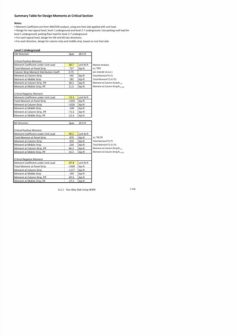
7/17/2019 Structural Design Project of Super Tall Building Chicago Spire
http://slidepdf.com/reader/full/structural-design-project-of-super-tall-building-chicago-spire 403/474
6.0 Foundation Design
6.1
Retaining Wall 2206.1.1
Soil Profile at Site 221
6.1.2
Effective Soil Pressure Calculations 222
6.1.3
Retaining Wall Design 22
6.1.
Retaining Wall !astan "nal#sis 22$
6.2 Par%ing &arage 230
6.2.1 '(o)Wa# Sla* +sing WWR 231
6.2.2
Par%ing &arage Colu,ns
6.2.2.1
Parking Garage Column with Rebar 247
6.2.2.2
Parking Garage Column with W-Shape 248
6.2.3
-elled Caisson Design 2
6.3 'o(er Foundation 250
6.3.1
"*a/us "nal#sis of Caissons 251
6.3.2 !ega)Colu,n Caisson Design 253
6.3.3 Ring -ea, Design 255
6.3.
Core Caisson Design 25
6.3.5
Caisson Re*ar 25

7/17/2019 Structural Design Project of Super Tall Building Chicago Spire
http://slidepdf.com/reader/full/structural-design-project-of-super-tall-building-chicago-spire 404/474
6.1 Retaining Wall
6.1.1 Soil Profile at Site 221
6.1.2 Effective Soil Pressure Calculations 222
6.1.3 Retaining Wall Design 224
6.1.4 Retaining Wall astan Anal!sis 22"

7/17/2019 Structural Design Project of Super Tall Building Chicago Spire
http://slidepdf.com/reader/full/structural-design-project-of-super-tall-building-chicago-spire 405/474
6 .
1 .
1 S o
i l P r o f i l e a
t S i t e
C r e a t e d B y : N T 5 / 1 1 / 2 0 1 2
T h e j o b s i t e i s l o c a t e d n e x t t o L a k e M i c h i g a n a n d t h e C h i c a g o i ! e r s o t h
e " a t e r t a b l e i s ! e r y h i g h # T h e
s o i l c o n s i s t s o $ a ! a r i t e y o $ s a n d s a n d c l a y s
t h a t " e r e
c a l l e d o % t i n t h e g e o t e c h n i c a l r e & o r t #
6 . 1 . 1
S
o i l P r o f i l e a t S i t e
C-221

7/17/2019 Structural Design Project of Super Tall Building Chicago Spire
http://slidepdf.com/reader/full/structural-design-project-of-super-tall-building-chicago-spire 406/474
6.1.2 Effective Soil Pressure Calculation
Calculating effective pressure and horizontal force to be used in retaining wall design.
ser Input
Density (ρ) (pcf) Effective ressure (psf)! "orizontal #orce (plf$ft run)!!
% % %
&' &*& +*'*
,% &*-& &-
,% &*+' &*
,% &*/* &/-%
,% &-%/ &/,% &-*+ +%&-
,% +%+* &*%+
,% +%' &-
/+. pcf Density of sand &' pcf
Density of clay ,% pcf
%.,%
Fourmulas
orewater pressure () 0 /+.!" "1 height in ft
/
,+
Density of 2ater
Created by 8=: $+,$+%&+
r #ir<$7tiff Clay Earth ressure Coefficient > a
Note: ?round water table is at ft depth as stated in the geotechnical report
!! "orizontal force 0 Effective ressure!>a @ ore ressure
! Effective ressure 0 (D !ρ) @ Effective pressure fro< layers above 1
Depth (d) (ft)
%
+
'
%
,&

7/17/2019 Structural Design Project of Super Tall Building Chicago Spire
http://slidepdf.com/reader/full/structural-design-project-of-super-tall-building-chicago-spire 407/474
7and
Clay
%
&%
+%
'%
.%
(%
/%
,%
*%
% (%% &%%% &(%% +%%% +(%%
D e p t h b e l o !
r o u
n " # f t $
Effective pressure #psf$

7/17/2019 Structural Design Project of Super Tall Building Chicago Spire
http://slidepdf.com/reader/full/structural-design-project-of-super-tall-building-chicago-spire 408/474
6.1.3 Retaining Wall Design Created By: NT 5/11/2012
User Input
Constant/Previous Calc.
Calc/Looup
!es Passes C"ec
No #ails C"ec
$a%i&u& Unsupported 'ei("t L 2) *t Cantilever at top o* +all, 2 -tories 2 -las
$ini&u& all T"icness ts,&in 2 in L/10 3CI )1 Tale 4.5 a6
3ctual all T"icness ts, act )0 in
3t -pansBar -i7e 8 19
3rea o* Bar 3ar 2.25 in2
L
ia&eter o* ar dar 1.;4 in
!ield -tren(t" o* Bars #y ;0 si
Bar -pacin( sspan ; in
Bar -i7e 8 19
3rea o* Bar 3ar 2.25 in2
ia&eter o* ar dar 1.;4 in
!ield -tren(t" o* Bars #y ;0 si
Bar -pacin( ssuport 1; in
$ini&u& steel ratio <( 0.001 per 3CI )1
3rea o* -teel =e>uired 3s 14 in2
<(?L?ts, act
Bar -i7e 8 ;
* 3 i2
esi(n tool *or a retainin( +all to resist soil pressures around t"e
e%terior o* t"e roundation. all "as een desi(ned as a si&ply
supported concrete sla, raced y t"e parin( (ara(e levels. T"e
top t+o storys are &odeled as a cantilever due to uncertainty in
soil conditions.
- u p p o r t s
Dimensions of Wall
Horizontal Shrinkage steel
3t -upports
esi(nin( *or 12 in vertical strip o* +all
Vertical Steel Bar Properties

7/17/2019 Structural Design Project of Super Tall Building Chicago Spire
http://slidepdf.com/reader/full/structural-design-project-of-super-tall-building-chicago-spire 409/474
Area of steel As 4.50 in2
=Abar*12/Sspan
Minimum Steel Required Asmin 0.65 in2
=!*b*" A#$ %1& 0&' (.12.2.1
)
+ension + 2(0 ,ips =As*f -
#ompression # 2(0 ,ips =+
#onrete Stren!t" f 4000 psi
eta 1 1 0.(5
#onrete #o3er 2 in A#$ ' %1&'0& ' (.(.1
Strutural ept" d 2( in = "''dbar
ei!"t of ompression fae a ( in =#/0.&5*f*b7
Moment Arm d'a/27 24 in
8ominal Moment Mn 5%( ,ip'ft =+*d'a/27
Strain in Steel 9s 0.006 :sin! Similar +rian!les
)
Stren!t" Redution ;ator < 0.0 ) o, >"en ?s @ 0.005
4&% ,ip'ft
Maimum Moment on Ball Mm %05 ,ip'ft ;rom MAS+A8
;ator of Safet- for )3erturnin! ;S 1.5
45& ,ip'ft Criniples of ;oundation Dn!ineerin!. -' raEa M. as
)
;S * Mm
< *
Check for Moments At Center of Spans
As F As ma G
As @ As min G
<*Mn @ ;S*Mm G

7/17/2019 Structural Design Project of Super Tall Building Chicago Spire
http://slidepdf.com/reader/full/structural-design-project-of-super-tall-building-chicago-spire 410/474
Area of steel As 1.6 in2 per 12 in >idt"
Minimum Steel Required Asmin 0.65 in2 = !*b*" A#$ %1& 0&' (.12.2.1
)
+ension + 101 ips =As*f -
#ompression # 101 ips =+
#onrete #o3er 2 in
#onrete Stren!t" f 4000 psi
eta 1 1 0.(5
Strutural ept" d 26 in = "''dbar
ei!"t of ompression fae a 2.4& in =#/0.&5*f*b7
Moment Arm d ' a/27 25 in
8ominal Moment Mn 210 ft',ips =+*d'a/27
Strain in Steel Hs 0.021 Similar +rian!les
)
Stren!t" Redution ;ator < 0.0 )
1& ft',ips
Maimum Moment on Ball Mm & ft',ips ;rom MAS+A8
;ator of Safet- for )3erturnin! ;S 1.5
14( ft',ips Criniples of ;oundation Dn!ineerin!. -' raEa M. as
)
Reference ' raEa M. as Criniples of ;oundation Dn!ineerin! Montere- #alif 1&4 p! 1
<*Mn @ ;S*Mm G
;S * Mm
<*Mn
As @ As min G
Hs @ 0.005G
Check for Moments At Supports

7/17/2019 Structural Design Project of Super Tall Building Chicago Spire
http://slidepdf.com/reader/full/structural-design-project-of-super-tall-building-chicago-spire 411/474
Total Retaining Height Ht 84 ft 7 Stories + 8 Slabs
Angle of friction for soil Ω 0.52 radians
Densit !f "la #cla 70 $sf %eotechnical Re$ort
Angle of &ac'fill Abo(e The )all * 0.7 radians
Ran'ine,s "oefficient -or assi(e /arth ressre '$ 0. 1tan45+ 322
Ran'ine,s assi(e /arth ressre $ 25.6 'i$s 10.5#claH2'$
Densit of Reinforced concrete #c 45 $sf
-actored Horiontal Sliding -orce 6 'i$s
9ertical -orce: Self )eight of )all 9 60.5 'i$s $er foot
"alclated -actor of Safet -or Sliding -S 2.2 19 tan2Ω6+$ cos*
!;
)orse "ase -ro< /ffecti(e ressre "alclation: Horiontal -orceHeight
NOTE - "hec'ing for rnning length of feet
Reference = &ra>a ?. Das: rinci$les of -ondation /ngineering: ?ontere: "alif: @84: $g @@
ndrained Shear Strength of 9er Stiff "la S 5 'sf %eotechnical Re$ort
Densit !f "la #cla 70 $sf %eotechnical Re$ort
9ertical Stress in Soil Ad>acent To The )all B C 'sf 1 #claheight
lti<ate &earing "a$acit of "la &" 2 'sf 1B+S
9ertical ressre De To )all 9& 2 'sf 1#co<creteHthh
!;
NOTE - "hec'ing for rnning length of feet
Reference -".R. "laton: E. ?ilitits' and )oods: /arth ressre and /arth=Retaining Strctres: 2nd /d.: "onference
blication FeG or' I A<erican Societ of "i(il /ngineers: @@6: : $g 54
Calculating Factor of Safety For Sliding
Bearing Capacity Check
Designing $er ft.
-S J .5 K
&" J 9& K

7/17/2019 Structural Design Project of Super Tall Building Chicago Spire
http://slidepdf.com/reader/full/structural-design-project-of-super-tall-building-chicago-spire 412/474
6.1.4 Retaining Wall Mastan Analysis
A 2-D Mastan model was created to obtain the induced moments and deflected shape of the parkinggarage retaining wall. Loads on the structure were obtained from the Effective Soil ressure !alculation.
"he# were modeled as resultant point loads of the distributed loads contributed b# each of the different
soil la#ers $sand% cla#% hard pan& from the Soil rofile along the height of the retaining wall. arking
floors provided supports and were modeled as fi'ities resisting the earth pressures. "he bottom of the
wall% on ver# hard cla#% was modeled as fi'ed and the top of the wall acted as a cantilever with a
ma'imum deflection of (.(()*+ in. ,igures of the Mastan output are included below. See also the
etaining all Design spreadsheet.
Retaining Wall Mastan Moment

7/17/2019 Structural Design Project of Super Tall Building Chicago Spire
http://slidepdf.com/reader/full/structural-design-project-of-super-tall-building-chicago-spire 413/474
Retaining Wall Mastan Deformed Shape

7/17/2019 Structural Design Project of Super Tall Building Chicago Spire
http://slidepdf.com/reader/full/structural-design-project-of-super-tall-building-chicago-spire 414/474
6.2
Par#ing $arage
6.2.1
%&o'Wa! Sla( )sing WWR 2316.2.2
Par#ing $arage Colu*ns
6.2.2.1 Parking Garage Column with Rebar 247
6.2.2.2
Parking Garage Column with W-Shape 248
6.2.3
+elled Caisson Design 24,
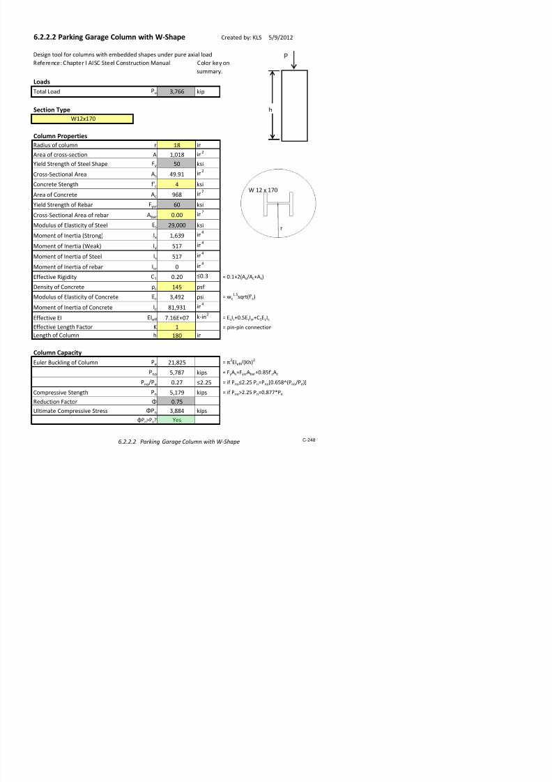
7/17/2019 Structural Design Project of Super Tall Building Chicago Spire
http://slidepdf.com/reader/full/structural-design-project-of-super-tall-building-chicago-spire 415/474
6.2.1 Two-Way Slab Using WWR Created by: MZ 5/10/2012
Nominal WWR Size Area [in2] Diameter [in]
D11 011 0!"5
D20 020 0500
D!1 0!1 0#25
D$$ 0$$ 0"50
D#0 0#0 0%"5
D"& 0"& 1000
Level 1 Underground
NS Direction !" #t S$an%
Ne'ati(e )o*iti(e Ne'ati(e )o*iti(e
+otal ,a-tored Moment M. [it] %2# $#! 2"5 1$!Widt3 o Stri [t] 1$! 1$! 1$! 1$!
WWR Area er 4inear ,oot A* [in2] 0%% 0%% 0!! 0!!
WWR Sele-ted D$$ D$$ D$$ D$$
ar Sa-in' or WWR me*3 * [in] #0 #0 1#0 1#0
ar* Needed or WWR me*3 2& 2& 11 11
&W Direction 2'.( #t S$an%Ne'ati(e )o*iti(e Ne'ati(e )o*iti(e
+otal ,a-tored Moment M. [it] "1# !%! 21# 115
Widt3 o Stri [t] 1$! 1$! 15% 15%
WWR Area er 4inear ,oot A* [in2] 0%% 0%% 0!! 0!!
6 %
WWR Re#erence Table
ar Size
6 !
6 $
Col.mn Stri Middle Stri
Col.mn Stri Middle Stri
6 5
6 #
6 "
Notes)
7 WWR 8Welded Wire Reinor-ement9 i* .*ed in*tead o traditional rebar* or arin' 'ara'e de*i'n7 n t3e ollo;in' WWR Reenren-e +able< =D= denoted a deormed ;ire +3e n.mber ollo;in' =D= 'i(e*
a -ro***e-tional area in 3.ndredt3* o a *>.are in-3 8AC !1% Aendi? @9
7 ar Size -ol.mn indi-ate* *ize o bar* .*ed to orm WWR *teel me*3

7/17/2019 Structural Design Project of Super Tall Building Chicago Spire
http://slidepdf.com/reader/full/structural-design-project-of-super-tall-building-chicago-spire 416/474
Level 2-* Underground
NS Direction !" #t S$an%
Ne'ati(e )o*iti(e Ne'ati(e )o*iti(e
+otal ,a-tored Moment M. [it] !0! 1#5 101 55Widt3 o Stri [t] 1$! 1$! 1$! 1$!
WWR Area er 4inear ,oot A* [in2] 0!1 0!1 0!1 02!
WWR Sele-ted D!1 D!1 D!1 D!1
ar Sa-in' or WWR me*3 * [in] 12 12 12 1#
ar* Needed or WWR me*3 15 15 15 11
&W Direction 2'.( #t S$an%
Ne'ati(e )o*iti(e Ne'ati(e )o*iti(e
+otal ,a-tored Moment M. [it] 2%0 1$5 %$ $$
Widt3 o Stri [t] 1$! 1$! 15% 15%
WWR Area er 4inear ,oot A* [in2] 0!1 0!1 0!1 02!
WWR Sele-ted D!1 D!1 D!1 D!1
ar Sa-in' or WWR me*3 * [in] 12 12 12 1#
ar* Needed or WWR me*3 15 15 1# 12
Col.mn Stri Middle Stri
Col.mn Stri Middle Stri

7/17/2019 Structural Design Project of Super Tall Building Chicago Spire
http://slidepdf.com/reader/full/structural-design-project-of-super-tall-building-chicago-spire 417/474
Parking Garage Reinforced Slab Design
Material Properties
Concrete Density ρc 110 pcf
Concrete Strength f'c 4,000 psi
Concrete Modulus Ec 2,410 ksi
WW !ield Strength "y #0 ksi
WW El$stic Modulus Es 2%,000 ksi
Load Cases Summary
Parking Floor
Sl$& Self Weight slf 110 psf ( ρc)h
Superi*posed De$d +o$d SD+ 42 psf
+ie +o$d ++ 40 psf
-ot$l "$ctored +o$d u 24. psf (1/2SWSD31/.++, SCE5610 2/7/2
Parking Roof
Sl$& Self Weight slf 110 psf
Superi*posed De$d +o$d SD 251 psf
+ie +o$d ++ 100 psf
Sno +o$d S+ 20 psf -ot$l "$ctored +o$d u .25 psf (1/2SWSD31/.++0/8S+, SCE5610 2/7/2
Design tool for WW Welded Wire einforce*ent3 of g$r$ge sl$&
(ρc1/8
)77)f'c192
: C 71#60# #/8, #/.
Notes:
; Sl$& for p$rking g$r$ge is designed using e<ui$lent fr$*e *ethod
; =ick positie $nd neg$tie *o*ent $t critic$l sections respectiely in e$ch direction to design
; ll the sl$& p$nels $re split into colu*n strips $nd *iddle strips/ "or e$ch $y>s design ?S $nd EW3, critic$l
*o*ents $re proportion$lly distri&uted to colu*n $nd *iddle strips
; Sl$& is designed ith drop p$nels $nd ithout interior &e$*s or edge &e$*s

7/17/2019 Structural Design Project of Super Tall Building Chicago Spire
http://slidepdf.com/reader/full/structural-design-project-of-super-tall-building-chicago-spire 418/474
asic Dimensions
@rid Sp$n, ?S Direction +?S 70/0 ft
@rid Sp$n, EW Direction +EW 2#/8 ft
Cle$r Sp$n, hicheer s*$ller +n 2./1 ft
Colu*n Strip Width &col 14/7 ft 9 e$ch side 0/28*in+?S, +EW3 C 71#60#
Middle Strip Width, ?S Direction &*,?S 14/7 ft 17/2/1
Middle Strip Width, EW Direction &*,EW 18/# ft
Column
Colu*n Di$*eter dcol 72/0 in
Di$*eter of E<ui/ Section de< 2#/4 in (0/#%)dcol, C 71#60# 17/./2/8
Slab
Sl$& -hickness h 12/0 in
Mini*u* Sl$& -hickness h*in 10/8 in (+n970, C -$&le %/8 c3
hAh*inB !esConcrete Coer on -op $nd t* c 2/0 in
Di$gr$* shoing &re$kdon of sl$& strips
Colu*n Strip
Colu*n @rid
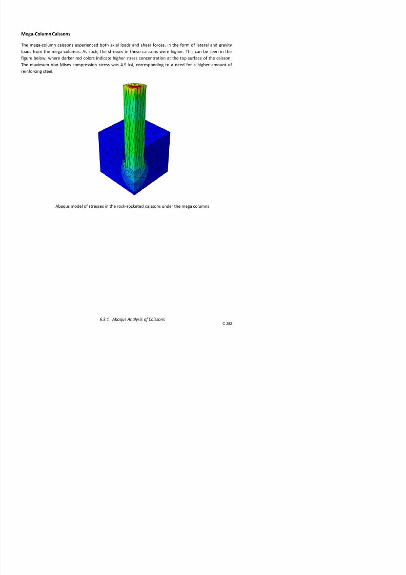
7/17/2019 Structural Design Project of Super Tall Building Chicago Spire
http://slidepdf.com/reader/full/structural-design-project-of-super-tall-building-chicago-spire 419/474
Drop Panel
Drop =$nel -hickness hdr 5/0 in
Mini*u* -hickness hdr,*in 7/0 in (0/28h, C 71#60# 17/2/8 $3
M$i*u* co*puting thickness 11/8 in (0/28det6de<923 C 71#60# 17/7/5
hdrAhdr,*inB !es
+ength of S<u$re Drop =$nel +dr 10/0 ft
Etent dist/ fro* Center Support distet 8/0 ft
distet,*in 4/58 ft (19.3*in+?S,+EW3, C 71#60# 17/2/8 &3
!esdistetAdistet,*inB
deEt
h
hdr
Cut Section of Colu*n 'ith Drop =$nel

7/17/2019 Structural Design Project of Super Tall Building Chicago Spire
http://slidepdf.com/reader/full/structural-design-project-of-super-tall-building-chicago-spire 420/474
Level 1 Underground
EW Direction Span 28.5 ft
Critical Positive Moment
Moment Coefficient under Unit Load 38. unit l!"ft Mastan #nal$sis
%otal Moment at Panel Strip 2 &ip"ft 'u(3)ft
Column Strip Moment Distri!ution Coeff. ).5 #C* 3+8")8 +3.,.-.+
Moment at Column Strip 5-5 &ip"ft %otal Moment().5
Moment at Middle Strip +82 &ip"ft %otal Moment(+").5/
Moment at Column Strip0 Plf 38.3 &ip"ft Moment at Column Strip1! col
Moment at Middle Strip0 Plf ++.5 &ip"ft Moment at Column Strip1! m0EW
Critical eative Moment
Moment Coefficient under Unit Load "2.3 unit l!"ft
%otal Moment at Panel Strip "+354 &ip"ft
Moment at Column Strip "+)2) &ip"ft
Moment at Middle Strip "3-) &ip"ftMoment at Column Strip0 Plf "+., &ip"ft
Moment at Middle Strip0 Plf "2+., &ip"ft
S Direction Span 3).) ft
Critical Positive Moment
Moment Coefficient under Unit Load -4.2 unit l!"ft
%otal Moment at Panel Strip 84 &ip"ft 'u(28.5ft
Moment at Column Strip ,54 &ip"ft %otal Moment().5
Moment at Middle Strip 22) &ip"ft %otal Moment(+").5/
Moment at Column Strip0 Plf -,.3 &ip"ft Moment at Column Strip1! col
Moment at Middle Strip Plf +- 3 &ip"ft Moment at Column Strip1! m S
Summary Table for Design Moments at Critical Section
Notes:
Moment Coefficient are from M#S%# anal$sis0 usin one foot sla! applied 'it6 unit load.
Desin for t'o t$pical level0 level + underround and level 2" underround. Use par&in roof load for
level + underround7 par&in floor load for level 2" underround.
or eac6 t$pical level0 desin for EW and S t'o directions.
or eac6 direction0 deisn for column strip and middle strip0 !ased on one foot sla!.

7/17/2019 Structural Design Project of Super Tall Building Chicago Spire
http://slidepdf.com/reader/full/structural-design-project-of-super-tall-building-chicago-spire 421/474
Level 2- Underground
EW Direction Span 28.5 ft
Critical Positive Moment
Moment Coefficient under Unit Load 3.3 unit l!"ft
%otal Moment at Panel Strip 2, &ip"ft
Moment at Column Strip 2) &ip"ft
Moment at Middle Strip ,4 &ip"ft
Moment at Column Strip0 Plf +-.5 &ip"ft
Moment at Middle Strip0 Plf -.- &ip"ft
Critical eative Moment
Moment Coefficient under Unit Load "+.4 unit l!"ft
%otal Moment at Panel Strip "53+ &ip"ft
Moment at Column Strip "344 &ip"ft
Moment at Middle Strip "+33 &ip"ft
Moment at Column Strip0 Plf "28.) &ip"ft
Moment at Middle Strip0 Plf "8.- &ip"ft
S Direction Span 3).) ft
Critical Positive Moment
Moment Coefficient under Unit Load --. unit l!"ft
%otal Moment at Panel Strip 3+- &ip"ft
Moment at Column Strip 235 &ip"ft
Moment at Middle Strip 8 &ip"ft
Moment at Column Strip0 Plf +,.5 &ip"ft
Moment at Middle Strip0 Plf 5.5 &ip"ft
Critical eative Moment
Moment Coefficient under Unit Load "82.) unit l!"ft
%otal Moment at Panel Strip "5, &ip"ft
Moment at Column Strip "-32 &ip"ftMoment at Middle Strip "+-- &ip"ft
Moment at Column Strip0 Plf "3).3 &ip"ft
Moment at Middle Strip0 Plf "+).+ &ip"ft

7/17/2019 Structural Design Project of Super Tall Building Chicago Spire
http://slidepdf.com/reader/full/structural-design-project-of-super-tall-building-chicago-spire 422/474
M!ST!N "ut#ut
9ne foot 'idt6 of sla! applied 'it6 unit load0 s6o'in critical desin moment coefficients.
38.,5
"2.25
Level + Underround0 EW Direction
"8.83
-4.+
Level + Underround0 S Direction
3.24
"+.4)
Level 2" Underround0 EW Direction
"82.)+

7/17/2019 Structural Design Project of Super Tall Building Chicago Spire
http://slidepdf.com/reader/full/structural-design-project-of-super-tall-building-chicago-spire 423/474
Design Calculations for WWR Concrete Slab Created by: MZ 5/10/2012
• All the reinforcement design are based on one foot slab.
• Leel 1 !orth"#o$th direction calc$lations hae been incl$ded as re%resentatie of the ty%ical calc$lations. &t
consists of %ositie and negatie moment reinforcement design for col$mn and middle stri% res%ectiely.
#hear 'as also chec(ed 'hen eer negatie moment is considered.
• )he *ast"+est direction of leel 1 and both directions of all other leels are calc$lated in the same manner b$t
'ith their indiid$al in%$ts.

7/17/2019 Structural Design Project of Super Tall Building Chicago Spire
http://slidepdf.com/reader/full/structural-design-project-of-super-tall-building-chicago-spire 424/474
Span Length LNS 30 ftCritical Moment Mu 46.3 kip-ft
Material Properties
Concrete Strength f'c 4,000 psi
!erage Concrete Strength f'c,a!g 3400 psi
"ar Si#e for $$% & 6
Nominal $$% Si#e 44
%e(ar rea (ar 0.44 in)
Nominal iameter *(ar 0.+0 in
$$% iel* Strength / 0 ksi
Flexural MMR Calculation (Per Foot Width)
Sla( 1hickness h 2).0 inConcrete Co!er c ).0 in
Sla( ffecti!e epth * .6 in 5h-c-*(ar)
$i*th ( 2).0 in
"ar Spacing s 6.0 in
$$% rea s 0. in) ma7.s526in. C8 32-0 3..3.+
1ension at iel* 1 +0 kips 5/s
epth of 9ui. Comp. Stress "lock a 2.+3 in. 51:(;f'c,a!g<
Nominal Moment Strength Mn 2.4 kip-ft 51:*-a)<
*=ustment actor for Moment > 0.
esign Moment Strength ?Mn 46.3 kip-ft
?Mn@Mu A es
Minimum %e9uire* Steel rea s,min 0.2 in) 50.002(h;60/, for / @ 60 ksi
s@s,minA es C8 32-0 +.2).).2
Level 1 Underground NS irection! Colu"n Strip! Positive Mo"en
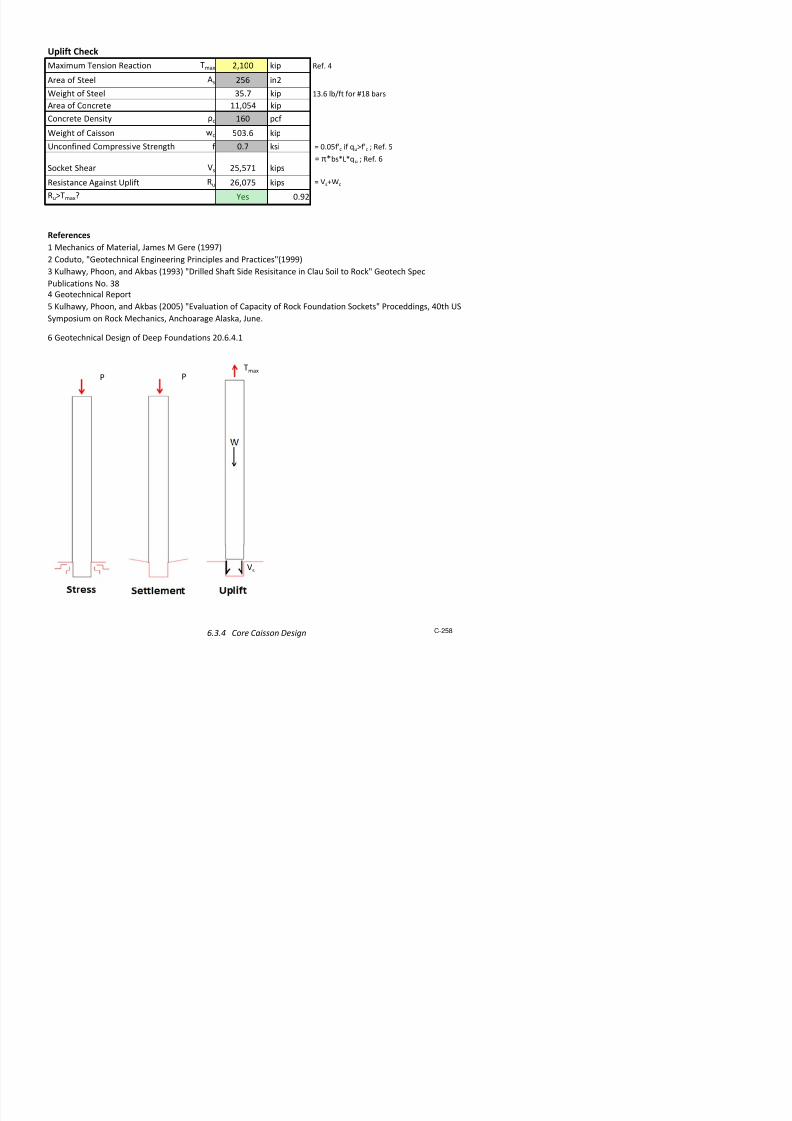
7/17/2019 Structural Design Project of Super Tall Building Chicago Spire
http://slidepdf.com/reader/full/structural-design-project-of-super-tall-building-chicago-spire 425/474
Span Length
LNS
30 ftCritical Moment Mu -82.6 kip-ft
Material Properties
Concrete Strength f'c 4000 p!i
"#erage Concrete Strength f'ca#g 3400 p!i
$ar Si%e for && ( 6
Nominal && Si%e )44e*ar "rea "*ar 0.44 in
2
Nominal )iameter +*ar 0.,0 in
&& iel+ Strength / 80 k!i
Flexural MMR Calculation (Per Foot Width)
Sla* 1hickne!! h 2.0 in
Concrete Co#er c 2.0 in
Sla* ffecti#e )epth + .6 in 5h-c-+*ar2
)rop 7anel 1hickne!! h+r ,.0 in
1otal ffecti#e )epth +tot 6.6 in 5+h+r
1otal Sla* 1hickne!! htot .0 in 5hh+r
Sla* $eam &i+th * 2.0 in
$ar Spacing ! 6.0 in
&& "rea "! 0.88 in2 ma9.!56in. "C: 38-08 3..3.,
1en!ion at iel+ 1 ,0 kip! 5/"!
)epth of ;ui. Comp. Stre!! $lock a .,3 in 51<*=f'ca#g>
Nominal Moment Strength Mn 2. kip-ft 51<+-a2>
"+?u!tment /actor for Moment @ 0.
)e!ign Moment Strength AMn 83.2 kip-ft
AMnBMu e!Minimum e;uire+ Steel "rea "!min 0.3 in
2 50.008*h=60/ for / B 60 k!i
"!B"!min e! "C: 38-08 ,.2.2.
Level 1 Underground NS irection! Colu"n Strip! Negative Mo"ent

7/17/2019 Structural Design Project of Super Tall Building Chicago Spire
http://slidepdf.com/reader/full/structural-design-project-of-super-tall-building-chicago-spire 426/474
MMR Shear Chec#
$eam Shear Check1otal /actore+ Loa+ Du 62, p!f
Length of ;ui. Column Section +e; 28.4 in
Shear at +tot )i!tance from Col. face Eu ,.8 kip!ft 5Du<LNS2-+e;2-+tot>
"+?u!tment /actor for Shear A 0., 5A<2=!;rt<f'c>=*=+tot>
Shear Strength AEc 8. kip!ft "C: 38-08 .2..
AEcBEu e!
7unching Shear Check 5Du=LNS=L&
1ri*utar "rea for one Column "tri 8 ft2 5Du<"tri-<+e;+tot>
2>
7unching Shear at +tot2 from Col. face Eu 2, kip! 54<+e;+tot>
7unching Shear 7erimeter *0 80 in
7unching Shear Strength AEc 6, kip! 5A<4=!;rt<f'c>=*0=+tot>
AEcBEu e!

7/17/2019 Structural Design Project of Super Tall Building Chicago Spire
http://slidepdf.com/reader/full/structural-design-project-of-super-tall-building-chicago-spire 427/474
Span Length LNS 30 ftCritical Moment Mu 14.3 kip-ft
Material Properties
Concrete Strength f'c 4,000 psi
!erage Concrete Strength f'c,a!g 3400 psi
"ar Si#e for $$% &
Nominal $$% Si#e (44
%e)ar rea )ar 0.44 in*
Nominal (iameter +)ar 0.0 in
$$% iel+ Strength / 0 ksi
Flexural MMR Calculation (Per Foot Width)
Sla) 2hickness h 1*.0 in
Concrete Co!er c *.0 in
Sla) ffecti!e (epth + . in 5h-c-+)ar6*
$i+th ) 1*.0 in
"ar Spacing s 1.0 in
$$% rea s 0.33 in* ma7.s51in. C8 31-0 3..3.
iel+ 2ension 2 * kips 5/s
(epth of 9ui. Comp. Stress "lock a 0. in. 526:);f'c,a!g<
Nominal Moment Strength Mn *0. kip-ft 52:+-a6*<
+=ustment /actor for Moment > 0.
(esign Moment Strength ?Mn 1.4 kip-ft
?Mn@Mu A es
Minimum %e9uire+ Steel rea s,min 0.1 in* 50.001)h;06/, for / @ 0 ksi
s@s,minA es C8 31-0 .1*.*.1
Level 1 Underground NS irection! Middle Strip! Positive Mo"ent

7/17/2019 Structural Design Project of Super Tall Building Chicago Spire
http://slidepdf.com/reader/full/structural-design-project-of-super-tall-building-chicago-spire 428/474
Span Length
LNS
30 ftCritical Moment Mu -27.5 kip-ft
Material Properties
Concrete Strength f'c 4000 p!i
"#erage Concrete Strength f'ca#g 3400 p!i
$e%ar Si&e for $ ( )
Nominal $ Si&e *44+ne ,ar "rea "%ar 0.44 in
2
Nominal *iameter %ar 0.750 in
$ iel Strength / 10 k!i
Flexural MMR Calculation (Per Foot Width)
Sla% hickne!! h 2.0 in
Concrete Co#er c 2.0 in
Sla% ffecti#e *epth .) in 6h-c-%ar2
*rop 8anel hickne!! hr 7.0 in
otal ffecti#e *epth tot ).) in 69hr
otal Sla% hickne!! htot .0 in 6h9hr
Sla% ,eam ith % 2.0 in
,ar Spacing ! ).0 in
$ "rea "! 0.33 in2 ma:.!6)in. "C; 31-01 3.5.3.7
iel en!ion 2) kip! 6/"!
*epth of <ui. Comp. Stre!! ,lock a 0.)5 in 6=%>f'ca#g?
Nominal Moment Strength Mn 3) kip-ft 6=-a2?
"@u!tment /actor for Moment A 0.
*e!ign Moment Strength BMn 32 kip-ft
BMnMu D e!Minimum $e<uire Steel "rea "!min 0.3 in
2 60.001%h>)0/ for / )0 k!i
"!"!minD e! "C; 31-01 7.2.2.
Level 1 Underground NS irection! Middle Strip! Negative Mo"ent

7/17/2019 Structural Design Project of Super Tall Building Chicago Spire
http://slidepdf.com/reader/full/structural-design-project-of-super-tall-building-chicago-spire 429/474
MMR Shear Chec#
,eam Shear Check
otal /actore Loa Eu
)27 p!f
Length of <ui. Column Section e< 21.4 in
Shear at tot *i!tance from Col. face Fu 7.1 kip!ft 6Eu=LNS2-e<2-tot?
"@u!tment /actor for Shear B 0.75 6B=2>!<rt=f'c?>%>tot?
Shear Strength BFc 1. kip!ft "C; 31-01 .2..
BFcFuD e!
8unching Shear Check 6Eu>LNS>L
ri%utar "rea for one Column "tri 155 ft2
6Eu="tri-=e<9tot?2?
8unching Shear at tot2 from Col. face Fu 527 kip! 64=e<9tot?
8unching Shear 8eremeter %0 10 in
8unching Shear Strength BFc 5)7 kip! 6B=4>!<rt=f'c?>%0>tot?
BFcFuD e!
o f
n

7/17/2019 Structural Design Project of Super Tall Building Chicago Spire
http://slidepdf.com/reader/full/structural-design-project-of-super-tall-building-chicago-spire 430/474
6 . 2 . 2 S u m
m a r y o f P a r k i n g G a r a g e C o l u m n
C r e a t e d b y : K L S
5 / 9 /
2 0 1 2
D e a d L o a d
D L
1 7 0
p s f
C o l o
r K e y :
U s e r I n p u t
T e r r a e L ! " e
L o a d
L L
1 0 0
p s f
C o n s t a n t / # r e " ! o u s C a l $
% o o f L o a d
& ' (
p s f
) 1 $ 2
D L * 1 $ '
L L
C a l / L o o + u p
T r ! b u t a r y , r e a
- & (
f t 2
. e s
# a s s e s C e +
L o a d o n C o l u
n
#
& 0 (
+ ! p s
o
a ! l s C e
L o a d s L e v e l s 1 - 7
D e a d L o a d
D L
1 7 0
p s f
# a r + ! n 3 4 a r a
3 e L ! " e L o a d
L L
1 ' 5
p s f
# a r + ! n 3 4 a r a
3 e L o a d
( ' -
p s f
) 1 $ 2
D L * 1 $ '
L L
T r ! b u t a r y , r e a
- & (
f t 2
L o a d o n C o l u
n
#
& 9 0 $ &
+ ! p s
C o n c r e t e P r o p e r t i e s
C o n r e t e S t r e n 3 t
f
( 0 0 0
p s !
C o n r e t e D e n s ! t y
6
0 $ 0
- & 9
l b / ! n &
C o " e r f o r C o l u n s
1 $
! n
C o " e r f o r C a ! s s o n s
& $
! n
4 a r a 3 e
l e " e l
C o l u n % a d ! u s
C o l u n
, r e a
C o l u n
e ! 3 t
L o a d o n
o l u n
D
S p ! r a l
% e ! n f o r e e n t
r a t ! o
S p ! r a l
% e b a r
S p ! r a l
S p a ! n 3
C o l u n
C a p a ! t y
8 " e r
D e s ! 3 n e d
, r e a o f
S t e e l
e ! 3 t f r o
S t e e l
, r e a o f
C o n r e t e
e ! 3 t f r o
C o n r e t e
e ! 3 t
C o l u n
! n
! n 2
! n
+ ! p s
S ! ; e
! n
6 s
S ! ; e
! n
< + ! p s =
>
< ! n 2 =
< + ! p s =
< ! n 2 =
< + ! p s =
< + ! p s =
1
1 2
( 5 2
2 7 (
& 1 ( $ 0
'
'
2 1
0 $ 0 0 9
&
2 $ 2
(
1 0 0 ( $ 1
2 1 9 $ -
2 $ '
(
0 $ 0
& (
( ( 9 $ 7
1 0 $ &
1 0 $ (
2
1 2
( 5 2
1 2 0
7 9 - $ 5
'
'
2 1
0 $ 0 0 9
&
2 $ 2
(
1 0 0 ( $ 1
2 5 $ 7
2 $ '
(
0 $ 0
1 5
( ( 9 $ 7
( $ 5
( $ 5
&
1 5
7 0 7
1 0 '
1 1 9 ' $ (
'
'
2 7
0 $ 0 0 7
&
2 $ 2
-
1 5 1 - $ 9
2 7 $ 0
2 $ '
(
0 $ 0
1 &
7 0 ( $ 2
' $ &
' $ &
(
1 5
7 0 7
1 0 '
1 5 9 ( $ 2
1 2
'
2 7
0 $ 0 0 7
&
2 $ 2
-
1 ' 0 7 $ -
0 $ 9
5 $ 2
-
0 $ 0
1 &
7 0 1 $ '
' $ 2
' $ &
5
1 5
7 0 7
1 0 '
1 9 9 2 $ 0
1 2
?
1 (
2 7
0 $ 0 0 7
&
2 $ 2
-
2 5 9 2 $ '
& 0 $ 1
( $ 7
1
0 $ 0
1 &
7 0 2 $
' $ 2
' $ &
'
1 -
1 0 1 -
1 0 '
2 & 9 & $ 2
1 2
?
1 (
& &
0 $ 0 0 '
&
2 $ &
1
2 5 9 2 $ '
- $ &
( $ 7
1
0 $ 0
1 &
1 0 1 & $ 2
9 $ 0
9 $ 0
7
1 -
1 0 1 -
1 0 '
2 7 9 ( $ 2
1 2
?
5 &
& &
0 $ 0 0 '
&
2 $ &
1
2 9 9 & $ (
7 $ 1
1 7 $ 0
0 $ 0
1 &
1 0 0 0 $ 9
- $ 9
- $ 9
C a ! s s o n
1 -
1 0 1 -
1 - 0
& 2 0 2 $ 1
1 2
?
1 7 0
& 0
0 $ 0 1 &
&
1 $ 1
0
& - - ( $ 1
2 1 $ &
( ( $ 7
0 $ 0
2 &
9 7 & $ 2
1 ( $ 7
1 ( $ 7
S t e e l S a p e
s
a p e
% e b a r
o o f L o a d s
T ! s ! s t e s u
a r y f o r t e p a r + ! n 3 3 a r a 3 e o l u n 3 e o e t r ! e s
a n d r e ! n f o r ! n 3
6 . 2 . 2
S u m m a r y o f P a r k i n g G a r a g e C o l u m n s
C-246
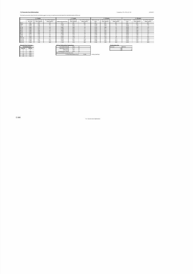
7/17/2019 Structural Design Project of Super Tall Building Chicago Spire
http://slidepdf.com/reader/full/structural-design-project-of-super-tall-building-chicago-spire 431/474
6.2.2.1 Parking Garage Column with Rebar Created by: KLS 5/9/2012
Design tool for concrete columns in paring garage reinforced !it" rebar# $
%sed for t"e &oof and Le'els 1() Color ey !it" summary#
Load on Column - Roof
Dead Load DL 1*0 psf L
+errace Li'e Load LL 100 psf
&oof Load ),- psf . 1#2DL1#,LL
+ributary rea )- ft2
Load on Column $ )0- ips
oment 0 ip(ft
Dc
Concrete Properties
Concrete Strengt" f3c -4000 psi
Concrete Density c 0#0 lb/in)
Co'er for Columns ccol 1#5 in
Co'er for Caissons ccais ) in
Column esign - Roof Load
6arage le'el 1 Co'er
Column &adius r 12 in
Column rea g -52 in2
. 7r2
Column 8eig"t " 2*- in
Load on column $ )1- ips includes self(!eig"tuantity of &ebar n ,
&ebar Sie ; , inimum , < C= 10#)
Dc 21#0 in . 2r(2>Co'er?
Steel @ield Stengt" Ay ,0#0 si
Spiral &einforcement ratio s 0#01 . 0#-5>g/>7Dc2/-?(1?f3c/Ay
Spiral &ebar ; ) Sie
Diameter of Spiral &ebar ds 0#)*5 in
rea of single &ebar sr 0#11 in2
Spiral Spacing s 2#2- in . srB7>Dc(ds?/>7Dc2/-?s < C= 10#9#)
0#* C= 10#)#5#1
r
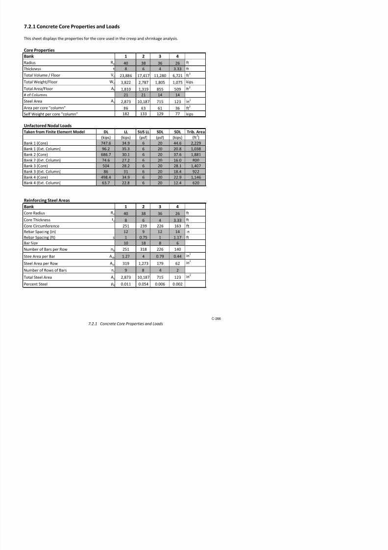
7/17/2019 Structural Design Project of Super Tall Building Chicago Spire
http://slidepdf.com/reader/full/structural-design-project-of-super-tall-building-chicago-spire 432/474
6.2.2.2 Parking Garage Column with W-Shape Created by: KLS 5/9/2012
Design tool for columns wit embedded sa!es under !ure a"ial load
#eference: Ca!ter $ %$SC Steel Construction &anual Color 'ey on
summary(
Loads
)otal Load *u +,-.. 'i!
Section Type
12"1-0
Column Properties
#adius of column r 1 in
%rea of crosssection % 1,01 in2
ield Strengt of Steel Sa!e 3y 50 'si
CrossSectional %rea %s 49(91 in2
Concrete Stengt fc 4 'si
%rea of Concrete %c 9. in2
ield Strengt of #ebar 3ysr .0 'si
CrossSectional %rea of rebar %bar 0(00 in2
&odulus of 6lasticity of Steel 6s 29,000 'si
&oment of $nertia 7Strong8 $" 1,.+9 in4
&oment of $nertia 7ea'8 $y 51- in4
&oment of $nertia of Steel $s 51- in4
&oment of $nertia of rebar $sr 0 in4
6ffectie #igidity C1 0(20 0(+ ; 0(1<27%s/%c<%s8
Density of Concrete =c 145 !sf
&odulus of 6lasticity of Concrete 6c +,492 !si ; wc1(5
s>rt7fc8
&oment of $nertia of Concrete $c 1,9+1 in4
6ffectie 6$ 6$eff -(1.6<0- 'in2
; 6s$s<0(56s$sr<C16c$c
6ffectie Lengt 3actor K 1 ; !in!in connection
Lengt of Column 10 in
Column Capacity
r
/ 12 " 1-0

7/17/2019 Structural Design Project of Super Tall Building Chicago Spire
http://slidepdf.com/reader/full/structural-design-project-of-super-tall-building-chicago-spire 433/474
6.2.3 Belled Caisson Design
Belled caissons distribute the load from the parking garage columns over a larger area to lower the
pressure to below the allowable bearing pressure of the soil, 45 ksf.
Load at boom of caisson
P 3767kip:= Parking arage !olumns."ls
Net Allowable Bearing Pressure on hardan
σ 45ksf := per eotechnical #eport
Area of Belled Caisson
$reaP
σ
%3.7&& ft'
⋅=:=
radius$rea
π
5.&6' ft⋅=:=
radius 5.5ft:=
rshaft &%in:=
# radius rshaft− 4 ft⋅=:=
$ngle must less than or e(ual
to 3) degrees per !hicago Building !ode*
#
tan 3)deg+ 6.-'% ft⋅=:=
* 7ft:=

7/17/2019 Structural Design Project of Super Tall Building Chicago Spire
http://slidepdf.com/reader/full/structural-design-project-of-super-tall-building-chicago-spire 434/474
6.3 %o&er -oundation
6.3.1 Abaqus Analysis of Caissons 251
6.3.2 Mega-Column Caisson Design 253
6.3.3
Ring eam Design 255
6.3.!
Co"e Caisson Design 25#
6.3.5
Caisson Reba" 25$

7/17/2019 Structural Design Project of Super Tall Building Chicago Spire
http://slidepdf.com/reader/full/structural-design-project-of-super-tall-building-chicago-spire 435/474
6.3.1 Abaqus Analysis of Caissons Created By: NT/JAC 5/11/2012
A finite element analysis using Abaqus was perfrmed t btain t!e ma"imum stresses e"perien#ed by t!e
r#$%s#$eted #aissns& T!ere were tw main types f #aissns' ea#! requiring different Abaqus mdels& T!ese
were t!e #aissns transmitting lads frm t!e #n#rete #re dwn t t!e bedr#$ and t!e #aissns
transmitting lads frm t!e mega%#lumns& (n eit!er #ase' t!e #aissns were mdeled as quartered #ylinders
embedded int t!e #rners bedr#$ #ubes' ta$ing ad)antage f t!e symmetry in t!e gemetry& (n t!e Abaqus
results' bluer #lrs indi#ate lwer stresses' w!ereas red #lrs indi#ate !ig!er stresses&
Core Caissons
T!e #re #aissns e"perien#ed nly a"ial lads in t!e frm f gra)ity lads frm t!e #n#rete #re& N s!ear
fr#es were applied n t!ese #aissns& As #an be seen in t!e figure belw' t!ere was a slig!t stress
#n#entratin at t!e tp f t!e #aissn w!ere t!e lad was applied& T!e ma"imum *n%+ises #mpressin
stress was ,&- $si' #rrespnding t a need fr minimum reinfr#ing steel&

7/17/2019 Structural Design Project of Super Tall Building Chicago Spire
http://slidepdf.com/reader/full/structural-design-project-of-super-tall-building-chicago-spire 436/474
Mega-Column Caissons
T!e mega%#lumn #aissns e"perien#ed bt! a"ial lads and s!ear fr#es' in t!e frm f lateral and gra)ity
lads frm t!e mega%#lumns& As su#!' t!e stresses in t!ese #aissns were !ig!er& T!is #an be seen in t!e
figure belw' w!ere dar$er red #lrs indi#ate !ig!er stress #n#entratin at t!e tp surfa#e f t!e #aissn&
T!e ma"imum *n%+ises #mpressin stress was ,&. $si' #rrespnding t a need fr a !ig!er amunt f
reinfr#ing steel&
Abaqus mdel f stresses in t!e r#$%s#$eted #aissns under t!e mega #lumns
6 3 2 Mega Column Caisson Design C t d b KLS 5/9/2012
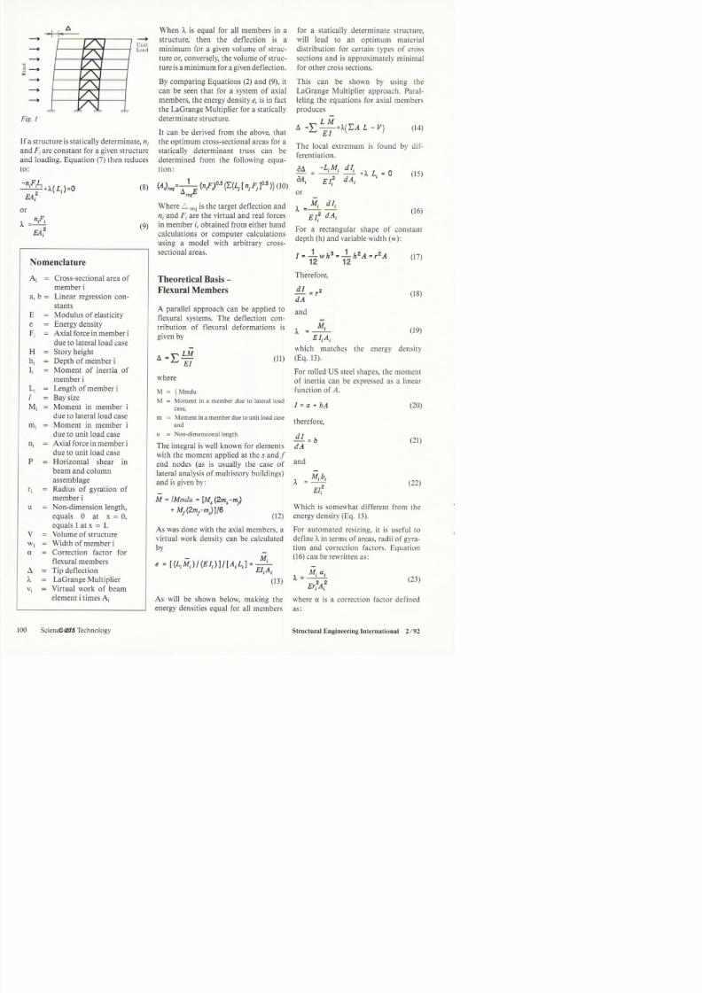
7/17/2019 Structural Design Project of Super Tall Building Chicago Spire
http://slidepdf.com/reader/full/structural-design-project-of-super-tall-building-chicago-spire 437/474
6.3.2 Mega-Column Caisson Design Created by: KLS 5/9/2012
Design tool for rock-socketed caissons suorting t!e "ega-colu"n
#ccetible$ %&S See botto" of calculation for diagra"'
( )*erdesigned 5'+,(
Concrete Co"ressi*e Strengt! fc 1+ ksi
Steel %ield Strengt! .y 5 ksi C!icago uilding Code
%oungs odulus edrock & 500 ksi ef' 13oissons atio edrock 4 0'2 ef' 2
&"erical Constant n 0'5 ef'
Det! to edrock L 1152 in
Det! in edrock Lo 102 in
Dia"eter of Caisson d 120 inDia"eter of Caisson socket bs 11+ in
Lengt! of Socket Ls 102 in
ini"u" Steel Casing 0'9 in 6 0'00,57d
#ctual Steel Casing Dia"eter dc 1 in
Deduct steel t!ickness for durability dd 0'0825 in
ega Colu"n otal ase eaction 552 kis
;eig!t of Connection 122 kis fro" idas <en
Colu"n Caisson ase eaction 3 5821+ kis
#llo=able Stress in Concrete >c +'81 ksi 6 0'[email protected]'5
@dc-ddAA/d
#llo=able Stress in rock >r +'18 ksi ef' +
#llo=able Stress >all +'18 ksi ini"u" of >c>r
#ctual Stress er Caisson >act 2' ksi 6 3/@Bd2/+A
.actor of Safety .S 2 6 >all/>act
0'+
2
Settlements
Material Properties
Dimensions
Forces and Stresses
plift Check

7/17/2019 Structural Design Project of Super Tall Building Chicago Spire
http://slidepdf.com/reader/full/structural-design-project-of-super-tall-building-chicago-spire 438/474
ai"u" ension eaction "a 2+ ki idas <en
#rea of Steel #s 8,2 in2
;eig!t of Steel +91 ki 1'8 lb/ft for 1 bars#rea of Concrete 108 in
2
Concrete Density Ec 180 cf
;eig!t of Caisson =c 115 ki
Co"ressi*e Strengt! f 0', ksi 6 0'05fc if FuGfc H ef' 5
Socket S!ear Is 255,1'1 kis 6 B7bs7L7f H ef' 8
esistance #gainst Jlift u 28,08 kis
uG"a$ %es 0'12
!eoretical uerbound k 9
oriontal Subgrade odulus k! 2150 ksf/ft
S!ear Strengt! of rock Su +55528 ksf 6 8,7k!7sFrt@d71ftA H ef' +
Lateral 3ressure taken by rock >! +'10&?0, k/ft 6 k7d7Su
S!ear Caacity of ock Ir +'10&?0 kis 6 >!7d
ai"u" S!ear I"a +0000 kis fro" idas <en
.actor of Safety .S +
Design S!ear I 180000 kis 6 I"a7.S
IrGI$ %es
References
+ <eotec!nical eort
1 ec!anics of aterial Ma"es <ere @199,A
Shear Check
Kul!a=y 3!oon and #kbas @199A NDrilled
S!aft Side esisitance in Clau Soil to ockN
<eotec! Sec 3ublications Oo'
2 Coduto N<eotec!nical &ngineering 3rinciles
and 3racticesN@1999A
5 Kul!a=y 3!oon and #kbas @2005A
N&*aluation of Caacity of ock .oundation
SocketsN 3roceddings +0t! JS Sy"osiu" on
ock ec!anics #nc!oarage #laska Mune'
plift Check
9"aC
3 3

7/17/2019 Structural Design Project of Super Tall Building Chicago Spire
http://slidepdf.com/reader/full/structural-design-project-of-super-tall-building-chicago-spire 439/474
6.3.3 Ring Beam Design
A ring beam will be used to connect the core walls to the caissons. This is designed to even distribute
the axial load to the caissons and to resist that shear forces from the core.
Ring Beam Properes
hring 8ft:= Height of Ring Beam
router 47ft:= Outer Radius of Ring Beam
rinner ft:= !nner Radius of Ring Beam
rcaissons "ft:= Radius of #aissons
Aring π router$
⋅ πrinner$
− "%8.& ft$
⋅=:=
Acaissons $' π rcaissons$
⋅⋅ %"7'.8 ft$
⋅=:=
Aslab π rinner$
⋅ 4$%.$ ft$
⋅=:=
A Aring Aslab+ Acaissons− "&( ft$
⋅=:= )*ec+ve Area for ,ric+on
Soil Properes
-u ('''lbf
ft$
:= ndrained -hear -trength / 0eotechnical Re1ort
ρcla2 7'lbf
ft
:= 3enist2 of #la2
3enist2 of aterρw &$.4
lbf
ft
:=
5e 4(.$ft:=
ρe ρcla2 ρw+:= )*ec+ve 3ensit2

7/17/2019 Structural Design Project of Super Tall Building Chicago Spire
http://slidepdf.com/reader/full/structural-design-project-of-super-tall-building-chicago-spire 440/474
Design Base Shear: 49030 kip (from Midas en!
core 4(''i1:=
&$'7." i1⋅=
core> "es
,-
core
%.=:=
Created by: KLS 5/9/20126.3.4 Core Caisson Design

7/17/2019 Structural Design Project of Super Tall Building Chicago Spire
http://slidepdf.com/reader/full/structural-design-project-of-super-tall-building-chicago-spire 441/474
y / /
Design tool for rock-socketed caissons suorting t!e core
See botto" of calculation for diagra"#
Overall Check
$ccetible% &'S
( )*erdesigned 29#+0(
Concrete Co"ressi*e Strengt! f,c 1 ksi
Steel &ield Strengt! .y 5 ksi C!icago uilding Code
&oung,s odulus edrock ' 500 ksi 3ef# 1
4oisson,s 3atio edrock 0#26 3ef# 2
'"erical Constant n 0#5 3ef#
Det! to edrock L 92 in
Det! in edrock Lo 102 in
Dia"eter of Caisson d 120 in
Dia"eter of Caisson socket ds 11 in
Lengt! of Socket Ls 102 in
7u"ber of Caisson 20 8 0#00+5d
ini"u" Steel Casing 0#9 in
$ctual Steel Casing Dia"eter dc 1 in
Deduct steel t!ickness for durability dd 0#025 in
Core 3eaction at 'le*ation80 +601 kis fro" idas ;en
Core <all <eig!t elo= 'le*ation80 219+0 kis
Core Caisson >otal ase 3eaction 4 0069 kis includes self-=eig!t
$llo=able Stress in Concrete ?c #1 ksi 8 0#f,
c@A.
y
1#5Ad
c-d
dBB/d
$llo=able Stress in rock ?r #1 ksi 3ef#
$llo=able Stress ?all #1 ksi ini"u" of ?c?r
$ctual Stress er Caisson ?act 1#++ ksi 8 4/Ad2/B
.actor of Safety .S 2 ? /?
6.3. Co e Ca sso es g
Material Properties
Dimensions
Forces and Stresses
Uplift Check

7/17/2019 Structural Design Project of Super Tall Building Chicago Spire
http://slidepdf.com/reader/full/structural-design-project-of-super-tall-building-chicago-spire 442/474
ai"u" >ension 3eaction >"a 2100 ki 3ef#
$rea of Steel $s 25 in2
<eig!t of Steel 5#+ ki 1# lb/ft for E16 bars
$rea of Concrete 1105 ki
Concrete Density Fc 10 cf
<eig!t of Caisson =c 50# ki
Gnconfined Co"ressi*e Strengt! f 0#+ ksi 8 0#05f,c if HuIf,c J 3ef# 5
Socket S!ear s 255+1 kis
3esistance $gainst Glift 3u 20+5 kis 8 s@<c
3uI>"a% &es 0#92
eferences
;eotec!nical 3eort
;eotec!nical Design of Dee .oundations 20###1
1 ec!anics of aterial a"es ;ere A199+B
2 Coduto M;eotec!nical 'ngineering 4rinciles and 4racticesMA1999B
Kul!a=y 4!oon and $kbas A199B MDrilled S!aft Side 3esisitance in Clau Soil to 3ockM ;eotec! Sec
4ublications 7o# 6
5 Kul!a=y 4!oon and $kbas A2005B M'*aluation of Caacity of 3ock .oundation SocketsM 4roceddings 0t! GS
Sy"osiu" on 3ock ec!anics $nc!oarage $laska une#
8 bsLHu J 3ef#
44>"aD
6.3.5 Caisson Rebar Created by: KLS 5/9/2012

7/17/2019 Structural Design Project of Super Tall Building Chicago Spire
http://slidepdf.com/reader/full/structural-design-project-of-super-tall-building-chicago-spire 443/474
Caisson Properties
Radius r 5 ft User Input
Area A 11,310 in2
Cnstant/!re"ius Ca#$%
Stee# &ie#d Stren't( )y *0 +si Ca#$/L+up
&es !asses C(e$+
Top of Mega-column Caissons )ai#s C(e$+
Stress at -p . %9 +si Abaus de#
aiu -ensin )r$e - 55,14 +ip .6A
Area f Stee# As 92 in2
-/)y
Area f 7bedded Stee# S(ape 282 in2
Area f Rebar eeded *52 in2
ar Sie ; 14
Area f Rebar Abar in2
uber f ars 1*4A$tua# Area f Stee# As<a$tua# 9 in
2
Asa$tua#=As &es
Bottom of Mega-column Caissons
Stress at tt . 1%9 +si Abaus de#
aiu -ensin )r$e - 21,44 +ip .6A
Area f Stee# As 354 in2
-/)y
ar Sie ; 14
Area f Rebar Abar in2
uber f ars 90
A$tua# Area f Stee# As<a$tua# 3*0 in2
Asa$tua#=As &es
Core Caissons
Stress in Cre Caissn . 1%2 +si Abaus de#
aiu -ensin )r$e - 13,582 +ip .6A
Area f Stee# As 22* in2
-/)y
-(is spreads(eet $a#$u#ates t(e aunt f rebar needed inside t(e $aissns
C#r Key
7 0 Creep and Shrinkage

7/17/2019 Structural Design Project of Super Tall Building Chicago Spire
http://slidepdf.com/reader/full/structural-design-project-of-super-tall-building-chicago-spire 444/474
7.0 Creep and Shrinkage
7.1 Steel Column Deformation 261
7.1.1
Steel Column Properties and Loads 262
7.1.2
Steel Column Deformation Calculations 263
7.2 Concrete Core Deformation 26
7.2.1 Concrete Core Properties and Loads 266
7.2.2 Concrete Core Deformation Calculations 267
CONSTRUCTION
ENDS
0
5
10
15
20
25
0 5 10 15 20
C o r e D i s p l a c e m e n t ! i
n c h e s "
#ime !$ears"
Displacement %&er 20 'ears
Concrete Core
Summary
STEEL
COLUMNS
7.1 Steel Column Deformation

7/17/2019 Structural Design Project of Super Tall Building Chicago Spire
http://slidepdf.com/reader/full/structural-design-project-of-super-tall-building-chicago-spire 445/474
Floors
Deflection per
floor
Local Def
per floor
group
Global
Deformation Sum
Lobby 0.979 0.979 0.98 inches
5-! 0.077 0.9" .90 inches
7-"8 0.0!7 0.805 ".7 inches
"9-#9 0.057 0.!# #.#$ inches
$0-5 0.0$9 0.590 #.9# inches
5"-!# 0.0$ 0.$9" $.$" inches
!$-7# 0.0#$ 0.##5 $.75 inches
7$-8! 0.05$ 0.70" 5.$! inches
87-99 0.0$" 0.5$! !.00 inches
00-0 0.0# 0.#$0 !.#$ inches
-"" 0.0" 0."5 !.59 inches
"#-## 0.0" 0.# !.7" inches
#$-$5 0.00$ 0.0$5 !.77 inches
!.77 inches%ltimate Steel Deformation&
t ' " years
7#0
Calculated
Days
(his chart reflects the )eformation of the steel columns for each floor group an) the o*erall steel
)eformation at a time of " years.
7.1.1 Steel Column Properties and Loads
Summary of column an) core )imensions an) the loa)s applie) on each

7/17/2019 Structural Design Project of Super Tall Building Chicago Spire
http://slidepdf.com/reader/full/structural-design-project-of-super-tall-building-chicago-spire 446/474
Column Properties Lobby 5-16 17-28 2-! "#-51 52-6! 6"-7! 7"-86 87- 1##-11# 111-122 12!-1!! 1!"-1"5
+olumn )imensions
)epth ) $0 $0 $0 $0 $0 $0 $0 #! #! #! #! #! #! in
base b $0 $0 $0 $0 $0 $0 $0 #! #! #! #! #! #! inconcrete Strength f,c $000 $000 $000 $000 $000 $000 $000 $000 $000 $000 $000 $000 $000 psi
conc. mo)ulus 57000s/rtf,c1 2c !7$$ !7$$ !7$$ !7$$ !7$$ !7$$ !7$$ !7$$ !7$$ !7$$ !7$$ !7$$ !7$$ 3si
(otal 4rea 4t 9"8 9"8 9"8 9"8 9"8 9"8 9"8 !88 !88 !88 !88 !88 !88 in
+oncrete 4rea c 0 0 0 0 0 0 0 0 0 0 0 0 0
Steel Shape& 6%- 6%- 6%- 6%- 6%- 6%- 6%- 6%-" 6%-" 6%-" 6%-" 6%-" 6%-"
4rea 4 9"8 9"8 9"8 9"8 9"8 9"8 9"8 !88 !88 !88 !88 !88 !88 in"
)epth d #! #! #! #! #! #! #! "8 "8 "8 "8 "8 "8 in
i)th of flange bf #! #! #! #! #! #! #! #! #! #! #! #! #! in
thic3ness of flange tf 0 0 0 0 0 0 0 0 0 0 0 0 0 in
thic3ness of eb tw 0 0 0 0 0 0 0 0 0 0 0 0 0 in
Steel atio ϱg .000 .000 .000 .000 .000 .000 .000 .000 .000 .000 .000 .000 .000
Steel Shape Self eight 87.5 $.# $.# $.# $.# $.# $.# #0.! #0.! #0.! #0.! #0.! #0.! 3ips
((4L +L%:; S2LF 2<G=( 88 $ $ $ $ $ $ # # # # # # 3ips
Core Properties
6an3 " $
a)ius $0 #8 "! ftthic3ness 8 ! #.## ft
(otal >olume ? Floor "!5"7 8900 777 ft#
(otal eight?Floor $"$$ #0"$ $8 3ips
(otal 4rea?Floor "00 $#" 5$$ ft"
@ of +olumns " " $
4rea per core AcolumnA 9! !8 #9 ft"
S per core AcolumnA "0" $$ 8" 3ips
$nfactored %odal Loads
6an3 +ore1 #5.! #$.9 "0 $$.! """9
6an3 2Bt. +olumn1 9!." #5.# "0 "0.8 0#8
6an3 " +ore1 #".7 #0. "0 #7.! 88
6an3 " 2Bt. +olumn1 7$.! "7." "0 !.0 800
6an3 # +ore1 #!.0 "8." "0 "8. $07
6an3 # 2Bt. +olumn1 8!.0 #.0 "0 8.$ 9""
6an3 $ +ore1 #5.! #$.9 "0 "".9 $!
6an3 $ 2Bt. +olumn1 !#.7 "".8 "0 ".$ !"0
!
!
SDL psf1
DL
3ips1
LL
3ips1
S%S LL
psf1
!
!
!
!
!
!
90
#
#!$
9#7
SDL
3ips1
(rib. 4rea
ftC"1
$
90$
#!
!5
7.1.1 Steel Column Properties and Loads
7.1.2 Steel Column Deformation Calculations
(his is a representati*e calculation performe) in the same manner for all floor sets +reep an) Shrin3age calculations per GL"000 :etho) from 4+< "09 " "7

7/17/2019 Structural Design Project of Super Tall Building Chicago Spire
http://slidepdf.com/reader/full/structural-design-project-of-super-tall-building-chicago-spire 447/474
(his is a representati*e calculation performe) in the same manner for all floor sets. +reep an) Shrin3age calculations per GL"000 :etho) from 4+< "09."-"7
6an3
Floor Group
Column Properties
f c "81 psiE' $000 psi ) $0 in s 0.# from table 4.$
f cm"8 4-9$1 !00 psi b $0 in 3 .5 from table 4.$
le*el 0 f,c $000 psi shu 5#8 microstrain 4-991
first le*el 5 2c !7$$ 3si h 0.7$ relati*e humi)ity from ;ational +limatic Data +enter a*erage
last le*el !.0 4t 9"8 in"
Hh 0.!9$ 4-001
total )ef t ' #yr1 0.9 inches 4c 0 in"
tc )ays1 $ time )rying begins
total )ef t ' "0yr1 0.9 inches 6%- t0 )ays1 $ time loa) is applie)
floors )ay en)e) 4s 9"8 in" Itc1 hen t0'tc
6an3 Loa) #7.5 3ips #0 "0 d #! in
6an3 " Loa) 5.9 3ips #$ "5! bf #! in
6an3 # Loa) 77.7 3ips #7 $0$ tf 0 in
6an3 $ Loa) !".9 3ips #$ 5$0 tw 0 in
2s "9000 3si ϱg
4s 9"8 in"
4c 0.0 in"
height 58 in*?s 0.0 in
t g l o
b a l
t l o
c a l
H e 4 - 9 7 1
f c m t t 1 4 - 9 ! 1
2 c 3 s i 1 4 - 9 5 1
H t - t c 1 4 - 0 1
+ o r r e c t e ) S h r i n 3 a
g e
4 - 9 8 1
+ r e e p + o e f f i c i e n t 4 -
0 # 1
J s D L 3
i p 1
J s S D L 3
i p 1
J s t o t a l 3
i p 1
f c 3
s i 1
e l a s t i c s t r a i n
u n r e i n f o r c
e )
6 a
n 3
; u m b e r
o f
+ o l u m n s ? + o l u m n
S t e e l D e f o r m a t i o n
J L ? 4
2 1
) e f o r m a t i o n
"5 9"! 5$9" #$.$ !".# 97 0.097" 0.00000 # 0.00 0.000!
"! " "7# !0" !8.7 !".# # 0.0"9# 0.00000 # 0.00 0.0008
"7 # "#"5 !"7# 0#. !".# !5 0.0#85$ 0.0000 # 0.00 0.000
"8 $ "999 !$"9 #7.5 !".# "00 0.0$77 0.0000 # 0.00 0.00"
"9 5 #$80 !5#7 .00 #7#."# .7 7.8 "$.5 "9! 0.0798 0.0000 # 0.00" 0.007
#0 ! #8$! !!9 .00 #7#."# .9 "0!." "$.5 ## 0.08## 0.0000 # 0.00" 0.009
# 7 $#7 !!8# .00 #7#."# ".0 "$0.! "$.5 #!5 0.090!5 0.0000 # 0.00" 0.00"
#" 8 $#77 !7#5 .00 #7#."# ". "7$.9 "$.5 #99 0.0999! 0.0000 # 0.00" 0.00"#
## 9 $578 !778 .00 #7#."# "." #09.# 8!.8 $9! 0."$9$ 0.0000" # 0.00# 0.00"9
#$ 0 $75 !8! .00 #7#."# "." #$#.! 8!.8 5#0 0.#$## 0.0000" # 0.00# 0.00#
&alues for Creep and S'rin(a)e analysis
5 - !
7.1.2 Steel Column Deformation CalculationsC-263

7/17/2019 Structural Design Project of Super Tall Building Chicago Spire
http://slidepdf.com/reader/full/structural-design-project-of-super-tall-building-chicago-spire 448/474
7.2 Concrete Core Deformation Created by: ADV, JDM, SJR, DSF 4/28/2012
This sheet summaries !a"ues #r$m the %a"%u"ati$& 'a(es i& a& easy t$ read #$rmat a&d %a"%u"ates the t$ta" de#$rmati$&s $# the %$re)

7/17/2019 Structural Design Project of Super Tall Building Chicago Spire
http://slidepdf.com/reader/full/structural-design-project-of-super-tall-building-chicago-spire 449/474
De#$rmati$&
'er F"$$r
De#$rmati$& 'er
F"$$r Se(me&t
Sum $# F"$$r Se(me&t
De#$rmati$&s De#$rmati$& 'er F"$$r
De#$rmati$& 'er
F"$$r Se(me&t
Sum $# F"$$r Se(me&t
De#$rmati$&s
De#$rmati$& 'er
F"$$r
De#$rmati$& 'er
F"$$r Se(me&t
Sum $# F"$$r Se(me&t
De#$rmati$&s
De#$rmati$& 'er
F"$$r
De#$rmati$& 'er
F"$$r Se(me&t
Sum $# F"$$r Se(me&t
De#$rmati$&s
F"$$rs *i&+ *i&+ *i&+ *i&+ *i&+ *i&+ *i&+ *i&+ *i&+ *i&+ *i&+ *i&+
$bby 0)-0. 0)-1 0)- 0)-1. 0)-2 0)- 0)-0 0)- 0)- 0)-1 0)- 0)41 0)0- 0)88 1)2 0)0 0).0 1)2 0)08- 0).. 1)- 0)088 1)0 1)4
128 0)0 0) 2)0 0)0 0)80 2)0 0)04 0)88 2)2 0)08 0).4 2)4
2.-. 0)0 0)2 2) 0)08 0)4 2) 0)04 0)1 2). 0)08 0) -)1
401 0)004 0)04 2) 0)004 0)0 2) 0)004 0)0 -)0 0)00 0)0 -)2
2- 0)00- 0)04 2) 0)00- 0)04 2) 0)004 0)0 -)0 0)004 0)0 -)2
4- 0)00- 0)0- 2) 0)00- 0)0- 2)8 0)00- 0)0- -)1 0)004 0)04 -)-
48 0)11 2)22 4). 0)180 2)-4 )1 0)204 2) ) 0)220 2)8 )1
8.. 0)1-4 1)4 ) 0)142 1)84 )0 0)12 2)11 )8 0)1 2)2 8)4
100110 0)100 1)10 ) 0)10 1)18 8)1 0)12- 1)- .)2 0)1-- 1)4 .).
111122 0)-. )4 14)2 0) ).1 1)0 0)4 ). 1)2 0)1 8). 18)4
12-1-- 0)-0. -)-. 1) 0)--- -) 18) 0)-88 4)2 21)4 0)41. 4)1 2-)1
1-414 0)100 1)20 18)8 0)110 1)-- 20)0 0)1-2 1)8 2-)0 0)14 1)4 24)8
Concrete Core Summary 20-Year Deformation Comparisons Construction Line
C$re De#$rmati$&: 2 4)8 i& Time *yr+ De# *i&+
Time (yr) Def (in) Stee" De#$rmati$&: ) i& 1)4 0
0 0 Di##ere&%e: 18)0 i& 1)4 2
2 18)8 C$m'e&sati$& / #"$$r 0)12 i&
- 20)0 Add ar$u&d 203 t$ a%%$u&t #$r err$r
10 2-)0 3 T$ta" De#$rmati$& at 2 yr ).3 de#*2yr+/de#*20yr+
20 24)8
t = 20 years
Total Deformation
t = 2 years t = 3 years t = 0 years
7.2 Concrete Core DeformationC-265
7.2. Concrete Core !roperties an" Loa"s

7/17/2019 Structural Design Project of Super Tall Building Chicago Spire
http://slidepdf.com/reader/full/structural-design-project-of-super-tall-building-chicago-spire 450/474
This sheet dis'"ays the 'r$'erties #$r the %$re used i& the %ree' a&d shri&5a(e a&a"ysis)
Core !roperties#an$ 2 3 %
Radius R$ 40 -8 - 2 #t
Thi%5&ess t 8 4 -)-- #t
T$ta" V$"ume / F"$$r V% 2-,88 1,41 11,280 ,21 #t-
T$ta" 6ei(ht/F"$$r 6% -,822 2,8 1,80 1,0 5i's
T$ta" Area/F"$$r At 1,810 1,-1. 8 0. #t2
7 $# C$"um&s 21 21 14 14
Stee" Area As 2,8- 10,18 1 12- i&2
Area 'er %$re %$"um& 8 - 1 - #t2
Se"# 6ei(ht 'er %$re %$"um& 182 1-- 12. 5i's
&nfactore" 'o"al Loa"s
Ta$en from (inite )lement *o"el DL LL S&S LL SDL SDL Tri+. ,rea
*5i's+ *5i's+ *'s#+ *'s#+ *5i's+ *#t2
+9a&5 1 *C$re+ 4) -4). 20 44) 2,22.
9a&5 1 *:;t) C$"um&+ .)2 -)- 20 20)8 1,0-8
9a&5 2 *C$re+ 8) -0)1 20 -) 1,881
9a&5 2 *:;t) C$"um&+ 4) 2)2 20 1)0 800
9a&5 - *C$re+ 04 28)2 20 28)1 1,40
9a&5 - *:;t) C$"um&+ 8 -1 20 18)4 .22
9a&5 4 *C$re+ 4.8)4 -4). 20 22). 1,14
9a&5 4 *:;t) C$"um&+ -) 22)8 20 12)4 20
-einforcin Steel ,reas
#an$ 2 3 %
C$re Radius R$ 40 -8 - 2 #t
C$re Thi%5&ess t% 8 4 -)-- #t
C$re Cir%um#ere&%e 21 2-. 22 1- #t
Rebar S'a%i&( *i&+ 12 . 12 14 i&
Rebar S'a%i&( *#t+ s 1 0) 1 1)1 #t
9ar Sie 10 18 8
<umber $# 9ars 'er R$= &b 21 -18 22 140

7/17/2019 Structural Design Project of Super Tall Building Chicago Spire
http://slidepdf.com/reader/full/structural-design-project-of-super-tall-building-chicago-spire 451/474
7.2.2 Concrete Core Deformation Calculations
This sheet 'er#$rms %ree' a&d shri&5a(e %a"%u"ati$&s 'er the @2000 m$de" #r$m AC 20.)2R2) This sheet %a"%u"ates the de#$rmati$&s #$r #"$$r 10, =hi%h is mid"e!e" i& the 1 #"$$r se(me&t)
9a&5 1
F"$$r @r$u' 1
#an$ /nformation Core !roperties
#Bc 14000 'si C$re Radius R$ 40 #t
# %m28 1100 'si 1)1#B% 00 AC20.R *A.4+ C$re Thi%5&ess t% 8 #t
10 C$"um& Area A( 1810 #t2
# 0 C$&%rete Area A% 1.0 #t2
# # 1 Stee" Area As 28- i&2
1)0 i& *# # # 0 1+Ed20yr Stee" Rati$ ρg 0)0110 As/A(
Loa"in alues for Creep an" S1rin$ae ,nalysis
1 2 - 4 Stre&(th De!e"$'me&t >arameter s 0)-- #r$m tab"e A)14
.-0 81. -- 5i's Ceme&t Ty'e C$rre%ti$& Fa%t$r 5 1 #r$m tab"e A)14
7 F"$$rs $# $ad -0 -4 - -4 "timate Shri&5a(e Gshu 48
mi%r$strai& .00E5E*4-0/# %m28+
0) AC 20.R *A..+
Day $adi&( &ded 120 2 404 40 day Re"ati!e Humidity h 0)14 <ati$&a" C"imati% Data Ce&ter a!era(e
Humidity C$rre%ti$& Fa%t$r I*h+ 0).4 *1 1)18Eh4+ AC 20.R *A100+
Curi&( Days t% 4 days time dryi&( be(i&s
*aterial !roperties A(e $# $adi&( t$ 4 days time "$ad is a''"ied
s 2.000 5si Dryi&( C$rre%ti$& Fa%t$r *t%+ 1 AC 20.R *A104+
As 28- i&2
A% 1.0 #t2
h 18 i&
V/S 42) i& V%/*2ER$+
Deformation Summary
>er F"$$r @r$u' u&its
2 years 0)0- 0)8 i&
- years 0)0 0).04 i&
10 years 0)08- 0)..4 i&
20 years 0)088 1)04 i&
V$"ume/Sur#a%e Rati$
Stee" "asti% M$du"us
Stee" Area
C$&%rete Area
F"$$r Hei(ht
9a&5
$ad
S'e%i#ied 28day C$m'ressi!e Stre&(th
Mea& C$&%rete C$m'ressi!e Stre&(th
First F"$$r i& Se(me&t
ast F"$$r i& Se(me&t
F"$$r 7 Mid"e!e"
"timate De#$rmati$& i& Se(me&t
7..2.2 Concrete Core Deformation CalculationsC-267
+
A . 2 +
* A . +
A 1 0 1 +
e d
( e * A . 8 +
$ e # # i % i e & t
a d ,
> s D
a d ,
> s S D
e S t r e s s ,
# %
S t r a i &
$ r % e d
t r a i &
$ r % e d
( e S t r a i &
D e # $ r m a t i $ &
% e d
a t i $ &
$ r % e d
R e i & # $ r % e d
i & # $ r % e d

7/17/2019 Structural Design Project of Super Tall Building Chicago Spire
http://slidepdf.com/reader/full/structural-design-project-of-super-tall-building-chicago-spire 452/474
t ( " $ b a "
t " $ % a "
I e * A .
# c m t * t +
* A
: % * 5 s i + *
I * t t % + * A
C $ r r e % t e
S h r i & 5 a (
C r e e ' C
* A 1 0 - +
S t e e " $
S t e e " $
> s t $ t a "
C $ & % r e t
: " a s t i % S
F & r e i & # $
C r e e ' S t
F & r e i & # $
S h r i & 5 a (
> % * # % +
: " a s t i % D
R e i & # $ r %
: " e a s t i %
D e # $ r m a
F & r e i & # $
R a t i $ $ #
t $ F & r e i
R % # i
9 a & 5
days days 'si 5si mi%r$strai& 5i's 5i's 5i's 5si i& i& i& 5i's *i&+ *i&+2 1 0)48 -,82- -,1 21 124 --. 0)01 0)00000 0)00000 0)00000 2 0)00000 0)0000 0)04 0).20 1
2 2 0)-2 ,42 4,8 422 122 44 0)0-0 0)00001 0)00000 0)00000 0)00001 0)00008 0)0.1 0).- 1
2 - 0)0. 8,088 ,1 2 120 48 0)04 0)00001 0)00000 0)00000 8- 0)00001 0)00010 0)100 0).41 1
28 4 0). .,2 ,08 0)0000 0)000 0)00 8-1 120 .1 0)0- 0)00001 0)00000 0)00000 11- 0)00001 0)00012 0)10 0).4 1
2. 0). 10,18 ,48 0)002 0)8 0)0 1,0-4 2-8 1,22 0)088 0)00002 0)00001 0)00000 1 0)00002 0)0001 0)110 0).4 1
-0 0)82- 10,.1 ,.-- 0)00-8 1)22 0). 1,2- 2- 1,44 0)10 0)00002 0)00001 0)00000 188 0)00002 0)0001 0)11- 0).48 1
K K K K K K K K K K K K K K K K K K K K K
144 120 1)0.0 1.,144 ,. 0)028 .)-2 1)8 2-,.-2 4. 24,-.1 2)2- 0)0002. 0)0002 0)00001 4,0-2 0)000-2 0)0022 0)142 0).0 1
280 2 1)11. 20,14 ,881 0)042- 1-)- 1).0 4,8 -8 48,144 4)4 0)0008 0)00110 0)00001 8,11 0)000- 0)004-8 0)14 0).1 2
428 404 1)1-1 20,0 ,. 0)0-- 1)2. 1). ,4 1.2 ,.4 )4. 0)00082 0)0011 0)00002 11,2 0)0008. 0)001- 0)14 0).1 -
4 40 1)1-8 20,84 8,00. 0)01 20)00 2)02 84,440 0)0 84,440 8)118 0)00101 0)0020 0)00002 14,28 0)00111 0)008 0)14 0).1 4
-0 0 1)144 21,04 8,04 0)00 22)88 2)0 84,440 0)0 84,440 8)1 0)00101 0)00210 0)00002 14,.4 0)00111 0)00 0)14 0).1 4
1,0. 1,01 1)11 21,-20 8,0.- 0)088 28)1 2)1 84,440 0)0 84,440 8)20- 0)00101 0)00218 0)0000- 14,80 0)00111 0)001 0)148 0).2 4
-,0 -,2 1)1 21,84 8,18 0)18 1)44 2)41 84,440 0)0 84,440 8)2.. 0)00101 0)00244 0)0000 14,81 0)00111 0)0044 0)10 0).2 4
,-00 ,2 1)10 22,044 8,221 0)2218 1).8 2)8 84,440 0)0 84,440 8)--2 0)00101 0)0022 0)0000 14,.12 0)00111 0)0041 0)10 0).2 4
"asti%
Strai&
Cree'
Strai&
Shri&5a(e
Strai&
T$ta"
De#$rmati$&
i& i& i& i&
0)00000 0)00000 0)000000 0)0000
0)00000 0)00000 0)000000 0)0000.
0)00000 0)00000 0)000000 0)00014
0)00000 0)00000 0)000000 0)0001.
0)00000 0)00000 0)000000 0)00044
0)00000 0)00000 0)000000 0)000.
K K K K
0)00004 0)0000 0)000001 0)01842
0)00008 0)0001 0)000002 0)0-82
0)00012 0)00024 0)00000- 0)0-8 S=it%h t$ 9a&5 2 $ad
0)0001 0)000-0 0)00000- 0)014 S=it%h t$ 9a&5 - $ad
0)0001 0)000-1 0)00000- 0)0-00 S=it%h t$ 9a&5 4 $ad
0)0001 0)000-2 0)000004 0)0-4 St$' A''"yi&( 9a&5 4 $ad
0)0001 0)000- 0)000008 0)0828
0)0001 0)000-. 0)000011 0)088
7..2.2 Concrete Core Deformation Calculations
8.0 References

7/17/2019 Structural Design Project of Super Tall Building Chicago Spire
http://slidepdf.com/reader/full/structural-design-project-of-super-tall-building-chicago-spire 453/474
8.1 Energy-Based Design of Lateral Systems by W.F. Baker 270
8.2 Geotechnical Report for the Chicago Spire 27
E n e r g y - B a s e d D e s i g n o f L a t e r a l S y s t e m s8.1

7/17/2019 Structural Design Project of Super Tall Building Chicago Spire
http://slidepdf.com/reader/full/structural-design-project-of-super-tall-building-chicago-spire 454/474
W i l l i a m 1 . B a k e r
A s s o c . P a r t n e r
S k i d m o r e , O w i n g s & M e r r i l l
C h i c a g o , I L , U S A
\ V i l l i a m F . B a k e r i s a n A s s o c i a t e P a r t n e r
a n d S e n i o r S t r u c t u r a l E n g i n e e r o f S k i d -
m o r e , O w i n g s & M e r r i l l , C h i c a g o , I l l i n o i s ,
U S A . A s A d j u n c t P r o f e s s o r o f A r c h i t e c t u r e
h e a l s o w o r k s a t t h e I l l i n o i s I n s t i t u t e o f
T e c h n o l o g y . H e w a s i n v o l v e d i n a n u m b e r
o f s i g n i f i c a n t p r o j e c t s , a m o n g s t t h e m t h e
S e a r s T o w e r R e v i t a l i z a t i o n , C h i c a g o ( 1 9 8 5 ) ,
t h e 6 3 s t o r y A T & T C o r p o r a t e C e n t e r ,
C h i c a g o ( 1 9 9 0 ) , a n d m o r e r e c e n t l y , i n 1 9 9 2 ,
t h e U S G B u i l d i n g , a 3 5 s t o r y o f f i c e
b u i l d i n g i n C h i c a g o .
T h e o r e t i c a l B a s i s —
A x i a l M e m b e r s
F r e q u e n t l y i n t h e d e s i g n o f h i g h - r i s e
b u i l d i n g s , t h e s t r u c t u r a l d e s i g n e r w a n t s
t o u s e t h e m i n i m u m m a t e r i a l t o r e s i s t a
p r e s c r i b e d w i n d l o a d w i t h o u t e x c e e d i n g
a d e f l e c t i o n c r i t e r i a ( s u c h a s t i p d e f l e c -
t i o n ) . I n e s s e n c e , t h e e x t e r n a l w o r k d o n e
b y t h e w i n d l o a d h a s b e e n p r e d e f i n e d .
T h e t a s k t h e n i s t o p r o p o r t i o n t h e s t r u c -
t u r e s o t h a t t h e i n t e r n a l w o r k i s a t t a i n e d
w i t h a m i n i m u m v o l u m e s t r u c t u r e . W e
k n o w f r o m v i r t u a l w o r k m e t h o d s t h a t
t h e d e f l e c t i o n a t t h e t o p o f a b r a c e d
s t r u c t u r e ( F i g . 1 ) i s g i v e n b y
A
( 1 )
w h e r e F i s t h e f o r c e i n a m e m b e r d u e t o
t h e l a t e r a l ( w i n d ) l o a d s , L / E A a r e t h e
g e o m e t r i c a n d m a t e r i a l p r o p e r t i e s o f a
m e m b e r , a n d n i s t h e f o r c e i n t h e
m e m b e r d u e t o a u n i t v i r t u a l l a t e r a l l o a d
a p p l i e d a t t h e t o p .
E q u a t i o n ( 1 ) c o n t a i n s s o m e v e r y u s e f u l
B y m o v i n g t h e m a t e r i a l f r o m o n e
m e m b e r t o a n o t h e r , i t i s p o s s i b l e f o r a l l
m e m b e r s o f t h e s t r u c t u r e t o h a v e e q u a l
e n e r g y d e n s i t i e s .
N o w t h e q u e s t i o n i s w h e t h e r t h e r e -
s u l t i n g s t r u c t u r e i s a m i n i m u m v o l u m e
s t r u c t u r e . T h i s c a n b e i n v e s t i g a t e d u s i n g
L a G r a n g e I u l t i p l i e r s . T h e a p p r o a c h i s
t o m i n i m i z e t h e d e f l e c t i o n o f t h e s t r u c -
t u r e a s g i v e n b y
n F L
s u b j e c t t o t h e c o n s t r a i n t t h a t i t h a s a
c o n s t a n t v o l u m e o f m a t e r i a l ( V ) . T h i s
c o n s t r a i n t c a n b e f o r m u l a t e d a s
g = E A L - v = O
A c o n s t r a i n e d d e f l e c t i o n e q u a t i o n m a y
t h e n b e w r i t t e n a s
A = f + A g
S u b s t i t u t i n g f o r f a n g f r o m E q u a t i o n s
( 3 ) a n d ( 4 ) r e s p e c t i v e l y :
A = E
' f _ + A ( L 4 L - )
A b s t r a c t
T h e s i z i n g o f t h e m e m b e r s o f t h e l a t e r a l r e s i s t a n c e s y s t e m f o r m u l t i - s t o r y b u i l d i n g s
i s o f t e n c o n t r o l l e d b y s t i f f n e s s r e q u i r e m e n t s . I n o r d e r t o a c h i e v e e c o n o m i c a l
b u i l d i n g s , i t i s i m p o r t a n t t h a t t h e s e m e m b e r s b e a p p r o p r i a t e l y s i z e d a n d t h a t t h e
s t r u c t u r a l m a t e r i a l s b e e f f i c i e n t l y d i s t r i b u t e d a m o n g t h e v a r i o u s c o m p o n e n t s . T h i s
p a p e r p r e s e n t s a s i z i n g t e c h n i q u e u t i l i z i n g e n e r g y m e t h o d s t h a t i s c u r r e n t l y i n u s e b y
s e v e r a l f i r m s i n v o l v e d i n t h e d e s i g n o f h i g h - r i s e b u i l d i n g s .
W h e n X i s e q u a l f o r a l l m e m b e r s i n a
— '
s t r u c t u r e ,
t h e n t h e d e f l e c t i o n i s a
U n i t
L o a d
m i n i m u m f o r a g i v e n v o l u m e o f s t r u c -
t u r e o r , c o n v e r s e l y , t h e v o l u m e o f s t r u c -
> 1 k b
f o r a s t a t i c a l l y d e t e r m i n a t e s t r u c t u r e ,
w i l l
l e a d
t o a n o p t i m u m m a t e r i a l
d i s t r i b u t i o n f o r c e r t a i n t y p e s o f c r o s s
s e c t i o n s a n d i s a p p r o x i m a t e l y m i n i m a l

7/17/2019 Structural Design Project of Super Tall Building Chicago Spire
http://slidepdf.com/reader/full/structural-design-project-of-super-tall-building-chicago-spire 455/474
F i g . 1
£ Y L
J .
I f a s t r u c t u r e i s s t a t i c a l l y d e t e r m i n a t e , n ,
a n d F 1 a r e c o n s t a n t f o r a g i v e n s t r u c t u r e
a n d l o a d i n g . E q u a t i o n ( 7 ) t h e n r e d u c e s
t o :
- n F L .
E A
t u r e i s a m i n i m u m f o r a g i v e n d e f l e c t i o n .
B y c o m p a r i n g E q u a t i o n s ( 2 ) a n d ( 9 ) , i t
c a n b e s e e n t h a t f o r a s y s t e m o f a x i a l
m e m b e r s , t h e e n e r g y d e n s i t y e , i s i n f a c t
t h e L a G r a n g e M u l t i p l i e r f o r a s t a t i c a l l y
d e t e r m i n a t e s t r u c t u r e .
I t c a n b e d e r i v e d f r o m t h e a b o v e , t h a t
t h e o p t i m u m c r o s s - s e c t i o n a l a r e a s f o r a
s t a t i c a l l y d e t e r m i n a n t t r u s s c a n b e
d e t e r m i n e d f r o m t h e f o l l o w i n g e q u a -
t i o n :
( 8 )
( A i ) r e q = 1 : e q E 1 F 1 ) ° 5 ( E ( L 1 F n F 1
] O . 5 ) )
( 1 0 )
W h e r e A
q
i s t h e t a r g e t d e f l e c t i o n a n d
n , a n d F , a r e t h e v i r t u a l a n d r e a l f o r c e s
( 9 )
i n m e m b e r i , o b t a i n e d f r o m e i t h e r h a n d
c a l c u l a t i o n s o r c o m p u t e r c a l c u l a t i o n s
u s i n g a m o d e l w i t h a r b i t r a r y c r o s s -
s e c t i o n a l a r e a s .
T h e o r e t i c a l B a s i s —
F l e x u r a l M e m b e r s
A p a r a l l e l a p p r o a c h c a n b e a p p l i e d t o
f l e x u r a l s y s t e m s . T h e d e f l e c t i o n c o n -
t r i b u t i o n o f f l e x u r a l d e f o r m a t i o n s i s
g i v e n b y
E l
w h e r e
N I =
M m d u
M = M o m e n t
i n a m e m b e r d u e t o l a t e r a l l o a d
m =
M o m e n t i n a m e m b e r d u e t o u n i t l o a d c a s e
u
= N o n - d i m e n s i o n a l l e n g t h .
T h e i n t e g r a l i s w e l l k n o w n f o r e l e m e n t s
o r
n . F .
F 4
f o r o t h e r c r o s s s e c t i o n s .
T h i s c a n
b e s h o w n b y u s i n g t h e
L a G r a n g e M u l t i p l i e r a p p r o a c h . P a r a l -
l e l i n g t h e e q u a t i o n s f o r a x i a l m e m b e r s
p r o d u c e s —
L M
,
= — _ _ + A ( E A L - v )
1 4 )
T h e l o c a l e x t r e m u m i s f o u n d b y d i f -
f e r e n t i a t i o n .
a
- L . M . d l .
— =
'
' _ _ - + A L . = O
( 1 5 )
0 A 1
E l 1 2
d A 1
o r
M .
d l .
, . L . _ . . L
( 1 6 )
2 - '
E l ,
"
F o r a r e c t a n g u l a r s h a p e o f c o n s t a n t
d e p t h ( h ) a n d v a r i a b l e w i d t h ( w ) :
I =
_ i - w h 3 = i h 2 A
= r 2 A
( 1 7 )
T h e r e f o r e ,
4 - L = 2
( 1 8 )
d A
a n d
A
=
( 1 9 )
E i A .
w h i c h m a t c h e s
t h e
e n e r g y
d e n s i t y
( 1 1 )
( E q . 1 3 ) .
F o r r o l l e d U S s t e e l s h a p e s , t h e m o m e n t
o f i n e r t i a c a n b e e x p r e s s e d a s a l i n e a r
f u n c t i o n o f A .
I = a + b A
( 2 0 )
t h e r e f o r e ,
( 2 1 )
d A
N o m e n c l a t u r e
A = C r o s s - s e c t i o n a l
a r e a o f
m e m b e r i
a , b = L i n e a r
r e g r e s s i o n c o n -
s t a n t s
E
= M o d u l u s
o f e l a s t i c i t y
e
=
E n e r g y
d e n s i t y
F 1
=
A x i a l
f o r c e i n m e m b e r i
d u e t o l a t e r a l l o a d c a s e
H = S t o r y
h e i g h t
=
D e p t h
o f m e m b e r i
= M o m e n t
o f i n e r t i a o f
m e m b e r i
L ,
=
L e n g t h
o f m e m b e r i
I
= B a y s i z e
=
M o m e n t
i n m e m b e r i
d u e t o l a t e r a l l o a d c a s e
m 1 =
M o m e n t
i n m e m b e r i
d u e t o u n i t l o a d c a s e
=
A x i a l
f o r c e i n m e m b e r i
c a s e ,
a n d
1
d 1 1
F o r r e c t a n g u l a r s h a p e s , a =
1 a n d f o r
( 2 4 )
S e r i e s I = a + b A
R a n g e o f
A v e r a g e
a
a
a
b
i n 4 )
i n 2 )

7/17/2019 Structural Design Project of Super Tall Building Chicago Spire
http://slidepdf.com/reader/full/structural-design-project-of-super-tall-building-chicago-spire 456/474
r o l l e d s h a p e s , a i s g i v e n i n T a b l e I ( a =
1 . 3 i s a r e a s o n a b l e v a l u e f o r t h e d e s i g n o f
c o m m o n l y u s e d s h a p e s i n s t r o n g a x i s
b e n d i n g ) .
A s w a s d o n e f o r a x i a l m e m b e r s , t h e o p -
t i m a l c r o s s - s e c t i o n a l a r e a f o r a s t a t i c a l l y
d e t e r m i n a n t f l e x u r a l m e m b e r c a n b e
d e t e r m i n e d f r o m :
— 0 . 5
0 . 5
— 0 . 5
1
M .
a .
L . M .
( A
=
'
i / r e q
E
r
0 . 5
r e q
i
I X ,
T 1
T h e a b o v e a s s u m e s t h a t t h e r a d i u s o f
g y r a t i o n ( r ) i s c o n s t a n t f o r a m e m b e r a s
t h e m e m b e r s c h a n g e s i z e
( t h i s i s
a
r e a s o n a b l e a s s u m p t i o n a s l o n g a s t h e
m e m b e r s t a y s i n t h e s a m e s e r i e s ) .
T h e o r e t i c a l B a s i s —
G e n e r a l
B e a m E l e m e n t
F o r a g e n e r a l b e a m e l e m e n t , t h e p e r t i -
n e n t d e f o r m a t i o n s a r e a x i a l , m a j o r a x i s
f l e x u r a l , m i n o r a x i s f l e x u r a l , m a j o r a x i s
s h e a r , m i n o r a x i s s h e a r a n d t o r s i o n a l .
T h e a b o v e s i z i n g t e c h n i q u e s c a n b e e x -
t e n d e d t o i n c l u d e a l l o f t h e s e d e f o r m a -
t i o n s . A l t h o u g h i t i s c l e a r t h a t a x i a l
d e f o r m a t i o n s a r e a d i r e c t f u n c t i o n o f
t h e c r o s s - s e c t i o n a l a r e a , t h e o t h e r d e -
f o r m a t i o n s m e r i t s o m e d i s c u s s i o n .
I n r e c t a n g u l a r c r o s s s e c t i o n s o f c o n s t a n t
d e p t h , t h e m a j o r a n d m i n o r a x i s s h e a r
s e c t i o n p r o p e r t i e s a r e l i n e a r f u n c t i o n s
o f c r o s s - s e c t i o n a l a r e a a n d t h e s e f u n c -
t i o n s a p p r o a c h z e r o a s t h e c r o s s - s e c -
t i o n a l a r e a a p p r o a c h e s z e r o . T h e r e f o r e ,
a p r o c e d u r e s i m i l a r t o t h o s e a b o v e
s h o w s t h a t a u n i f o r m e n e r g y d e n s i t y
2 0 0 0 0
1 9 0 0 0
1 8 0 0 0
1 7 0 0 0
1 6 0 0 0
1 5 0 0 0
1 4 0 0 0
1 3 0 0 0
1 2 0 0 0
1 1 0 0 0
1 0 0 0 0
9 0 0 0
8 0 0 0
7 0 0 0
6 0 0 0
5 0 0 0
4 0 0 0
3 0 0 0
2 0 0 0
1 0 0 0
0
F i g . 2
d u c e d f r o m t h e s a m e r o l l e r , t h e m a j o r
a n d m i n o r a x i s m o m e n t o f i n e r t i a s a n d
t h e m a j o r a n d m i n o r a x i s s h e a r a r e a s a r e
a p p r o x i m a t e l y l i n e a r f u n c t i o n s o f a r e a .
T h e s i z i n g t e c h n i q u e s p r e v i o u s l y d e s c r i -
b e d c a n b e u s e d f o r t h e c o r r e s p o n d i n g
A r e a ( i n 2 )
D e s i g n
A k e y p a r t o f t h e a b o v e d i s c u s s i o n i s t h a t
t h i s m e t h o d p r o v i d e s t h e m i n i m u m
v o l u m e o f m a t e r i a l f o r s t a t i c a l l y d e t e r -
m i n a t e s t r u c t u r e s ( s i n c e t h e m e m b e r
W 1 4 x 6 1 — 8 2
— 5 9
3 9 . 1
1 . 0 7 t o 1 . 0 9 1 . 0 8
W 1 4 x 9 0 — 1 3 2
— 1 4 6 4 3 . 2
l . l O t o l . l 5
1 . 1 2
W 1 4 x 1 4 5 — 4 2 6 — 9 3 7 5 8 . 7
l . l l t o 1 . 4 7 1 . 3 0
W l 4 x 4 5 5 — 7 3 0
- 4 6 4 0
8 7 . 4
l . 3 l t o l . 6 3 1 . 4 7
W 1 8
— 2 0 8 6 8 . 2 l . O 9 t o 1 . 3 8
1 . 2 1
W 2 1
— 3 8 5 9 2 . 8 l . l O t o 1 . 4 3
1 . 2 3
W 2 4 — 6 2 6 1 2 1 l . l 2 t o l . 4 5 1 . 2 5
W 2 7
— 9 4 6
1 5 2 l . l 4 t o 1 . 3 2 1 . 2 2
W 3 0 — 1 6 7 4
1 9 3
1 . l 6 t o 1 . 4 1
1 . 2 9
W 3 3 — 2 0 7 5 2 2 9
l . l 4 t o 1 . 3 5 1 . 2 4
W 3 6
— 2 4 4 5
2 5 7
l . l 2 t o 1 . 3 1
1 . 2 0
T a b l e I
( 2 5 )
. ' 1 u u u
W 3 6
+
V A L U E S F R O M S T E E L T A B L E S
—
L E A S T S Q U A R E S F I T F O R
I
= a + b A
W 3 3
W 1 4
0
2 0 4 0 6 0
8 0
1 0 0
1 2 0 1 4 0
1 0 0
1 8 0 2 0 0 2 2 0
1 i n = . 5 4 c m
- 3 . ' '
- 3
A l l o f t h e s e b r a c i n g s y s t e m s c a n b e c o n -
s i d e r e d s t a t i c a l l y d e t e r m i n a t e f o r l a t e r a l
l o a d s . E v e n X - b r a c i n g , w h i c h i s n o r m a l -
l y c o n s i d e r e d t o b e i n d e t e r m i n a t e , i s
b a s i s , i t m a y s t i l l b e v e r y u s e f u l t o a p p l y
t h e t e c h n i q u e t o t h i s t y p e o f s t r u c t u r e .
A s t h e m a t e r i a l a n d l o a d s a r e t r a n s f e r -
r e d f r o m o n e l a t e r a l s y s t e m t o a n o t h e r i t
- 3
- 3
- 3
- 3
- 3
_ _ _ _ _

7/17/2019 Structural Design Project of Super Tall Building Chicago Spire
http://slidepdf.com/reader/full/structural-design-project-of-super-tall-building-chicago-spire 457/474
d e t e r m i n a t e f o r l a t e r a l l o a d s w h e n t h e
d e s i g n e r m a k e s b o t h d i a g o n a l s i n a
s t o r y t h e s a m e s i z e ( w h i c h i s n o r m a l l y
t h e c a s e ) .
A n o t h e r s y s t e m t y p e w h i c h i s m o r e
p r o b l e m a t i c , i s w h e r e t h e r e a r e p a r a l l e l
s y s t e m s o f d i f f e r e n t
t y p e s s u c h a s
p a r a l l e l t r u s s e s o f d i f f e r e n t d e p t h s o r
c o m b i n a t i o n s o f p a r a l l e l t r u s s e s a n d
m o m e n t f r a m e s . F o r t h e s e s y s t e m s t h e
f o r c e l e v e l s i n t h e i n d i v i d u a l m e m b e r s
w i l l c h a n g e a s t h e m e m b e r s i z e s a r e
c h a n g e d . T h e r e f o r e , t h e m e t h o d n o l o n -
g e r c a n b e a s s u r e d o f g i v i n g m i n i m u m
v o l u m e s t r u c t u r e . A l t h o u g h t h e t e c h -
n i q u e n o l o n g e r h a s a c l e a r t h e o r e t i c a l
i s c o m m o n t o h a v e n e g a t i v e e n e r g y d e n -
s i t i e s .
T h i s o f t e n i n d i c a t e s t h a t t h e
m e m b e r s s h o u l d b e r e m o v e d f r o m t h e
s y s t e m . I f t h e i n t e r a c t i o n s c o n v e r g e o n a
r e a s o n a b l e s t r u c t u r e , i t u s u a l l y m u c h
l e s s r e d u n d a n t t h a n t h e i n i t i a l s t r u c t u r e .
T h e L a G r a n g e \ I u I t i p l i e r m e t h o d o l o g y
c a n a l s o b e a p p l i e d t o s u b s y s t e m s s u c h
a s a b e a m a n d c o l u m n a s s e m b l a g e ( F i g .
6 ) .
F o r t h i s s y s t e m , t h e c o n s t r a i n e d
d e f l e c t i o n e q u a t i o n f o r f l e x u r a l d e f o r -
m a t i o n i s a s f o l l o w s :
H 2 I H
i i
P j [ -
+ j +
( A H + A 6 l - v )
— 1
d I g
—
2
c i A
g
F o r r e c t a n g u l a r c r o s s s e c t i o n s
b e c o m e s :
1
r
W h e r e r a n d r a r e t h e r a d i i o f g y r a t i o n
f o r t h e g i r d e r a n d c o l u m n , r e s p e c t i v e l y .
F o r r o l l e d s h a p e s , E q u a t i o n 2 9 b e -
c o m e s :
I
b
0 . 5
. 1 = _ (
( 3 1 )
I
b
W h e r e
b g
a n d
b
c a n
b e t a k e n f r o m
- 3
- 3
- 3
- 3
I
h .
i g . 3
I
I .
.
I . 1 .
. T h e
n e x t c o n d i t i o n t o b e e x a m i n e d i s
w h e n t h e r e a r e m u l t i p l e p a r a l l e l l i n e s o f
b r a c i n g i n a b u i l d i n g ( F i g . 5 ) . T h i s i s t h e
t y p i c a l c a s e f o r b r a c i n g w h i c h i s a d j a -
c e n t t o c o r e e l e m e n t s s u c h a s e l e v a t o r
s h a f t s
a n d s t a i r w e l l s . A l t h o u g h t h e s e
a .
b . c .
d .
e .
f .
e l e m e n t s s h a r e t h e l a t e r a l s h e a r s a n d
F
4
m o m e n t s i n a s t o r y , t h e y o f t e n a r e p r o -
i g .
p o r t i o n e d o n a b a s i s o f t r i b u t a r y w i n d
l o a d . T h e r e f o r e , a s t h e y a r e s i m u l t a -
n e o u s l y r e s i z e d , t h e f o r c e s i n t h e m d i -
B r a c i n g
v i d u a l m e m b e r s d o n o t c h a n g e s i g n i -
( T y p . )
f i c a n t l y a n d b e h a v e a s t h o u g h t h e y w e r e
s t a t i c a l l y d e t e r m i n a t e .
F l o o r
P l a n
F i g . 5
• 1
I C
I l
4 I : -
- - - A . -
F i g . 6
C o l u m n : I , r , b
G i r d e r : ' g ' r g , b g
W h i c h r e d u c e s t o :
1 2 E 1 2 d A l 2 E j 2 d A
C
g
o r
1
d I
2 d A
( 2 7 )
( 2 8 )
( 2 9 )
t h i s
( 3 0 )
D i s p l a c e m e n t
( P r o p e r t y )
f ( A )
d
d A
L a G r a n g e
M u l t i p l i e r
E n e r g y
D e n s i t y
A x i a l
E l o n g a t i o n
( A )
A
1
F n
E A 2
,
F n
E A 2
M a j o r A x i s
F l e x u r e
A h 2
1 2
h 2
1 2
M
E I A
,
M
E J A
8.2 Geotechnical Report for the Chicago Spire

7/17/2019 Structural Design Project of Super Tall Building Chicago Spire
http://slidepdf.com/reader/full/structural-design-project-of-super-tall-building-chicago-spire 458/474

7/17/2019 Structural Design Project of Super Tall Building Chicago Spire
http://slidepdf.com/reader/full/structural-design-project-of-super-tall-building-chicago-spire 459/474
C-275

7/17/2019 Structural Design Project of Super Tall Building Chicago Spire
http://slidepdf.com/reader/full/structural-design-project-of-super-tall-building-chicago-spire 460/474

7/17/2019 Structural Design Project of Super Tall Building Chicago Spire
http://slidepdf.com/reader/full/structural-design-project-of-super-tall-building-chicago-spire 461/474
C-277

7/17/2019 Structural Design Project of Super Tall Building Chicago Spire
http://slidepdf.com/reader/full/structural-design-project-of-super-tall-building-chicago-spire 462/474

7/17/2019 Structural Design Project of Super Tall Building Chicago Spire
http://slidepdf.com/reader/full/structural-design-project-of-super-tall-building-chicago-spire 463/474
C-279

7/17/2019 Structural Design Project of Super Tall Building Chicago Spire
http://slidepdf.com/reader/full/structural-design-project-of-super-tall-building-chicago-spire 464/474

7/17/2019 Structural Design Project of Super Tall Building Chicago Spire
http://slidepdf.com/reader/full/structural-design-project-of-super-tall-building-chicago-spire 465/474
C-281

7/17/2019 Structural Design Project of Super Tall Building Chicago Spire
http://slidepdf.com/reader/full/structural-design-project-of-super-tall-building-chicago-spire 466/474

7/17/2019 Structural Design Project of Super Tall Building Chicago Spire
http://slidepdf.com/reader/full/structural-design-project-of-super-tall-building-chicago-spire 467/474
C-283

7/17/2019 Structural Design Project of Super Tall Building Chicago Spire
http://slidepdf.com/reader/full/structural-design-project-of-super-tall-building-chicago-spire 468/474

7/17/2019 Structural Design Project of Super Tall Building Chicago Spire
http://slidepdf.com/reader/full/structural-design-project-of-super-tall-building-chicago-spire 469/474
C-285

7/17/2019 Structural Design Project of Super Tall Building Chicago Spire
http://slidepdf.com/reader/full/structural-design-project-of-super-tall-building-chicago-spire 470/474

7/17/2019 Structural Design Project of Super Tall Building Chicago Spire
http://slidepdf.com/reader/full/structural-design-project-of-super-tall-building-chicago-spire 471/474
C-287

7/17/2019 Structural Design Project of Super Tall Building Chicago Spire
http://slidepdf.com/reader/full/structural-design-project-of-super-tall-building-chicago-spire 472/474

7/17/2019 Structural Design Project of Super Tall Building Chicago Spire
http://slidepdf.com/reader/full/structural-design-project-of-super-tall-building-chicago-spire 473/474
C-289

7/17/2019 Structural Design Project of Super Tall Building Chicago Spire
http://slidepdf.com/reader/full/structural-design-project-of-super-tall-building-chicago-spire 474/474