the sleipner co2 storage site
TRANSCRIPT

© 2015 EAGE www.firstbreak.org 61
special topicfirst break volume 33, June 2015
Earth Science for Energy and Environment
1 Statoil Research Centre, Arkitekt Ebbellsveg 10, N-7005, Trondheim, Norway.2 SCCS, School of GeoSciences, University of Edinburgh, Edinburgh EH9 3FE, Scotland. * Corresponding author, Email: [email protected]
The Sleipner CO2 storage site: using a basin model to understand reservoir simulations of plume dynamicsAndrew J. Cavanagh1*, R. Stuart Haszeldine2 and Bamshad Nazarian1 address the modelling challenge of simulating the layered CO2 plume, and present their insights into plume dynam-ics from applying both basin modelling and reservoir simulation approaches to matching the observed distribution.
W hen simulating CO2 storage, an accurate match to the observed CO2 plume distribution is a prerequi-site to establishing the dominant flow physics, and forecasting the storage site behaviour beyond the
observed and expected injection period. The scale of indus-trial CO2 storage pilots such as Sleipner, offshore Norway, is similar to that of small hydrocarbon fields, and lends itself to reservoir simulation. However, the reservoir conditions and dynamics are significantly different: oil and gas production are dominated by imbibition, which is suited to multi-phase Darcy flow simulation; whereas CO2 storage represents the injection of a non-wetting fluid that displaces the in situ brine. The latter process is often termed ‘drainage’, and with respect to simulation, is more typical of regional basin mod-elling and percolating oil and gas migration. The challenge of modelling CO2 storage is to accurately represent this drain-age displacement at the reservoir scale on short decadal time-scales. The advantage is the detailed observational dataset with which such models are constrained. Using a Darcy flow model, the first decade of reservoir simulations for Sleipner has been characterized by poor matches to the known plume distribution, and forecasted plume dynamics that persisted for decades-to-centuries beyond the injection period. To overcome this problem of poor simulated replication, and to test the veracity of long term plume dynamics, we applied a basin model to Sleipner, which simulated the gravity-domi-nated migration of a buoyant fluid using a capillary percola-tion method. The basin model achieved an accurate match to the observed CO2 plume distribution. This suggests that simple Darcy-based reservoir simulation forecasts are mis-leading. The basin modelling insights allowed us to revisit the reservoir simulations, and, focusing on benchmark models of the uppermost layers, approximate the gravity-dominated regime of percolating flow. A pressure-compensated black oil reservoir simulation accurately matches the distribution and dynamics of the uppermost layers. The reservoir simulations
also indicate that dissolution of CO2 will contribute sig-nificantly to storage within decades. While both approaches have their limitations, a combination of basin modelling and reservoir simulation provide perspectives that illuminate the dominant flow physics processes within the storage site, implying that the plume is in a state of dynamic equi-librium and likely to stabilize within years of the injection ending. Two challenges remain for the benchmark reservoir simulations: (A) how to represent the trapping and breaching behaviour of thin shale barriers for percolating CO2 within a storage formation; and (B) how to address pressure field arti-facts in larger regional Darcy flow models of CO2 storage.
A pioneering projectThe Sleipner carbon capture and storage project has demon-strated the technical feasibility of storing CO2 in geological formations since 1996. To date, over 15 Mt of CO2 has been injected into the Utsira Formation, a sandstone aquifer, 1 km beneath the seabed of the Central North Sea. Sleipner also happens to be one of the most remarkable fluid flow experi-ments of our time. The storage site has been monitored with geophysical surveys approximately every two years, building up a detailed image of the CO2 plume distribution and dynam-ics within the storage site. The plume is evidently layered and asymmetric, with the uppermost CO2 layers closely conform-ing to the mapped topography of the caprock and underlying thick shale, in a similar manner to the flat oil-water contacts of many hydrocarbon fields (Figure 1); the deeper plume has a similar spatial distribution, forming a tight vertical stack of thin asymmetric CO2 layers which are apparently trap-ping beneath mudstone barriers within the Utsira Formation (Cavanagh and Haszeldine, 2014). This paper addresses the modelling challenge of simulating the layered CO2 plume, and the insights gained into plume dynamics from applying both basin modelling and reservoir simulation approaches to matching the observed distribution.

special topic
Earth Science for Energy and Environment
www.firstbreak.org © 2015 EAGE62
first break volume 33, June 2015
ping is locally mapped from the baseline 1994 seismic survey, along with the trap topography of the overlying caprock seal (Figure 1).
A paradigm shift from viscous to percolating flow modelsThe frequent seismic and gravimetric surveying of the plume make the Sleipner CO2 plume an ideal candidate for numeri-cal flow modelling studies. Early attempts with conven-tional Darcy flow simulators failed to match the observed distribution of CO2 (Hellevang, 2006; Chadwick et al., 2006; Hermanrud et al., 2009). The flow physics assumed in such models requires viscous flow via a series of aligned holes in the shale barriers, and favors conceptual models with discrete vertical pathways such as chimneys, sand injectites, and sub-seismic faults. However, the estimated CO2 density from gravi-
The observed plume distributionEarly monitoring of the site showed that the plume had ascended more than 200 m vertically from the injection point (1012 mbsl) to the caprock from 1996 to 1999 (Arts et al., 2004). The plume had encountered and breached a series of thin shale barriers within the storage site, forming nine verti-cally stacked CO2 layers, each approximately 10-20 m thick, and extending laterally for a few hundred meters (Figure 2). Each stacked layer has a pronounced north-south elonga-tion, which is assumed to be the result of CO2 ponding in subtle topographic traps immediately beneath the thin intra-formational shale barriers that are observed in the Utsira Formation from adjacent well logs. Most of the barriers are too thin to be resolved seismically (Gregersen and Johannessen, 2001; Zweigel et al., 2004). However, the uppermost barrier is resolved as a 6 m thick shale, and the topographic trap-
Figure 1 Mapped oil-water contact for the Glitne oil field (left panel), in comparison to the fluid distribution and seal topography for the upper layers of the Sleipner CO2 plume circa 2006 (thick shale, middle panel; caprock, right panel). All three examples illustrate the asymmetric shape of near-flat fluid contacts, conforming to the local topography of the seal-reservoir interface.
Figure 2 A comparison of the observed Sleipner plume profile circa 2002 and 5 Mt of injected CO2 (left), to the capillary flow simulation (right), viewed from the southeast. The nine plume layers are well defined spatially, having ponded beneath thin intra-formational shales within the storage site. While a mass bal-ance is possible, the uncertainty relating to CO2 layer thickness is high. Ambient geothermal and hydrostatic pressure conditions are assumed. Modified from Cavanagh and Haszeldine (2014).

special topic
Earth Science for Energy and Environment
© 2015 EAGE www.firstbreak.org 63
first break volume 33, June 2015
stack of wide but thin CO2 layers that conform to the caprock and shale topography. The resultant migration simulation (Cavanagh and Haszeldine, 2014) provides a match to the layered plume distribution (Figure 2).
Mass balanceThe percolation flow model not only provides a good spatial match, but also appears to suggest a reasonable mass balance for the plume: the simulated fluid distribution under ambient hydrostatic pressure and temperature conditions accounts for the entire injected mass of CO2. However, confidence in the accuracy of the mass balance is undermined by uncertainty in three poorly constrained parameters: layer thickness, CO2 density, and gas saturation (Cavanagh and Haszeldine, 2014). As Figure 3 demonstrates, for the top layer alone, reasonable variations in these three parameters result in widely varying estimates of mass. Microgravity surveying suggests an average plume density of 675±20 kg/m3 (Alnes et al., 2011), which favours a cold plume interpretation, i.e. close to the ambient pressure and temperature conditions of the reservoir (Figure 3).
Intra-formational barrier threshold pressureThe migration model implies that the multiple thin layers of CO2 are caused by low threshold entry pressures for the shale barriers within the Utsira Formation (Cavanagh and Haszeldine, 2014). The barrier threshold pressures for CO2 are estimated at around 50 kPa, (Table 1), i.e. equivalent to around 200 μD and approximately 34-fold less than the 1.7 MPa laboratory measure on samples of the caprock shale that forms the top seal (Springer and Lindgren, 2006; Harrington et al., 2009). This difference is most plausi-bly explained by micro-fracturing of the shale barriers.
metric monitoring (Alnes et al., 2011) and lateral distribution of the layers (Bickle et al., 2007; Boait et al., 2012) are inher-ently at odds with the simulated pressure gradient required to match the vertical breakthrough rate via viscous flow along such pathways (Cavanagh and Haszeldine, 2014). The distri-bution of the CO2 layers appears to be a gravity-controlled migration and trapping of buoyant fluid beneath the barriers under near-hydrostatic pressure conditions, thus conforming to the caprock and shale topography by back-filling small trap structures. This results in a near-flat fluid contact that is similar in fashion to regional hydrocarbon migration and per-colating trap charge in petroleum systems (Cavanagh, 2013).
Hydrocarbon migration is known to percolate into trap structures at pressures close to ambient hydrostatic condi-tions, and requires a paradigm shift in numerical simulation (Carruthers, 2003). The boundary condition for the cessation of viscous Darcy flow and onset of percolating capillary flow is defined by Ca, the capillary number. This is simply a dimen-sionless ratio of the viscous force to the interfacial tension that controls percolation. For a capillary number of less than 10-5, buoyant fluids such as oil, gas, and CO2, percolate through the sedimentary strata as gravity-driven ganglia (England et al., 1987). An analysis of the observed rates of lateral and verti-cal flow observed at Sleipner (Ca ~10-7) is inconsistent with Darcy flow (Cavanagh and Haszeldine, 2014). An alternative modelling approach is used here, where the intra-formational shales act as laterally continuous barriers that trap the ascend-ing, percolating fluid. This migration model does not require unobserved a discrete vertical flow path phenomena; the CO2 simply backfills against each shale barrier, and breaks through when the buoyant force of the CO2 overcomes the capillary threshold pressure of the shale barrier. This results in a vertical
Plume layer Units L1 L2 L3 L4 L5 L6 L7 L8 L9 M/S
Crest depth (mbsl) 955 920 905 890 875 860 845 825 795 –
Mean depth (mbsl) 960 926 909 895 880 866 849 832 801 –
Layer thickness (m) 10.5 12 9 9.5 13 10.5 10 14.5 10 11
Volume (106 m3) 2.78 4.29 2.51 1.18 10.4 1.29 2.60 3.34 1.40 –
Pressure (MPa) 9.71 9.37 9.20 9.06 8.91 8.77 8.60 8.43 8.12 –
Temperature (°C) 39.5 38.6 38.1 37.7 37.3 36.9 36.4 35.9 35.0 –
Density (kg/m3) 616 606 602 597 589 582 571 551 355 –
Mass balance (Mt) 0.49 0.75 0.44 0.20 1.76 0.22 0.43 0.53 0.14 4.96
Mass balance (%) 0.10 0.15 0.09 0.04 0.35 0.04 0.09 0.11 0.03 0.99
Modelled Pth (kPa) 42 49 38 40 56 46 45 68 54 49
Equivalent k (mD) 0.3 0.2 0.3 0.3 0.1 0.2 0.2 0.1 0.1 0.2
Fracture width (μm) 2.6 2.2 2.8 2.7 1.9 2.3 2.4 1.6 2.0 2.3
Table 1 An estimated mass balance for Sleipner (5 Mt, 2002), calculated from the modelled CO2 volume and density (based on ambient pressure and temperature at layer mean depth). Volume is critically sensitive to CO2 layer thickness and gas density. This model assumes a mid-range temperature profile. Warmer models require slightly thicker CO2 layers to account for a mass balance. Colder models require slightly thinner CO2 layers. Threshold pressure, permeability, and fracture estimates are dependent on layer thickness and CO2 density. Final column, M/S: mean (thickness, pressure, permeability, fracture width) or sum (mass balance).

special topic
Earth Science for Energy and Environment
www.firstbreak.org © 2015 EAGE64
first break volume 33, June 2015
networks within the much thicker caprock are probably only proximal to the formation, and have a limited connectivity, preventing vertical migration through the overburden.
Sleipner BenchmarkThe basin modelling approach provides a reasonable plume match, and raises a significant challenge to conventional res-ervoir simulations of CO2 storage predicated on Darcy’s law, i.e. viscous flow under the influence of a pressure gradient in a continuum is a poor approximation of expected CO2 spatial distributions in storage formations. The migration model also highlighted key uncertainties related to mass estimation for CO2 storage sites in general. More significantly, the migration of buoyant fluids at near-hydrostatic conditions implies that
However, CO2 injection at Sleipner is not considered to be a likely cause of this fracturing, as the buoyant pressure at the top of each CO2 layer is very much less than that required to initiate fractures. We suggest fracture re-activation.
It is proposed that the micro-fracturing occurred long before CO2 injection commenced, as a result of pore pressure fluctuations associated with the rapid melting of thick ice sheets during multiple episodes of deglaciation in the region over the last million years (Cavanagh and Haszeldine, 2014). The overlying Nordland Group shales of the caprock may have also fractured during deglaciation. However, it is also noted that there is no evidence of CO2 leaking, possibly as a result of a different caprock response for CO2 retention relative to the thin shale barriers. It is inferred that fracture
Figure 3 Mass balance uncertainty related to plume density and layer thickness assumptions for the uppermost layer: (a) plume density variations assuming linear geothermal gradients and the common range of uncertainty associated with the plume temperature profile; (b) uppermost layer thickness versus mass for the uppermost CO2 layer, and related mass-balance estimates for the whole plume circa 2002 (equivalent to 5 Mt injected). The sensitivity of mass estimate for a single layer with respect to layer thickness is apparent (orange curves). A 10 m thick layer shows a mass variation of ±40% (80–200 kt), for a 35°C scenario, and a thickness uncertainty of ±4 m. As the trap fills, the volume and related mass increases rapidly. For gas layers with a fixed aerial footprint but uncertain thickness, it can be shown that the uncertainty in volume is equivalent to the error on thickness. Compounding this with density uncertainty, the solution space for a 5 Mt mass balance (gray trapezoid) varies from 50% (thin, warm layers) to 160% (thick, cool layers). Modified from Cavanagh and Haszeldine (2014).
Figure 4 The Sleipner Benchmark, viewed from the southeast (3x6 km; 780-880 mbsl); Mesh count: 550,000 cells (50:50:0.5 meters).The reservoir-scale model is constructed from detailed topographic maps of the caprock and thick shale; the remain-ing surfaces are layer cake.
special topic
Earth Science for Energy and Environment
© 2015 EAGE www.firstbreak.org 65
first break volume 33, June 2015
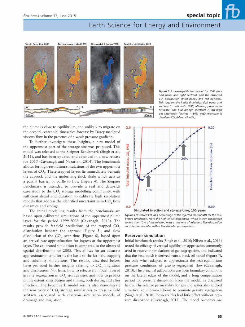
Reservoir simulationInitial benchmark results (Singh et al., 2010; Nilsen et al., 2011) tested the efficacy of vertical equilibrium approaches commonly used in reservoir simulations of gas segregation, and indicated that the best match is derived from a black oil model (Figure 5), but only when adapted to approximate the near-equilibrium pressure conditions of gravity-segregated flow (Cavanagh, 2013). The principal adaptations are open boundary conditions on the lateral edges of the model, and a long compensation period for pressure dissipation from the model, as discussed below. The relative permeability for gas and water also applied a vertical equilibrium scheme to promote gravity segregation (Singh et al., 2010); however this had little effect without pres-sure dissipation (Cavanagh, 2013). The model outcomes are
the plume is close to equilibrium, and unlikely to migrate on the decadal-centennial timescales forecast by Darcy-mediated viscous flow in the presence of a weak pressure gradient.
To further investigate these insights, a new model of the uppermost part of the storage site was proposed. This model was released as the Sleipner Benchmark (Singh et al., 2011), and has been updated and extended in a new release for 2015 (Cavanagh and Nazarian, 2014). The benchmark allows for high-resolution simulations of the two uppermost layers of CO2. These trapped layers lie immediately beneath the caprock and the underlying thick shale which acts as a partial barrier or baffle to flow (Figure 4). The Sleipner Benchmark is intended to provide a real and data-rich case study to the CO2 storage modelling community, with sufficient detail and duration to calibrate high resolution models that address the identified uncertainties in CO2 flow dynamics and storage.
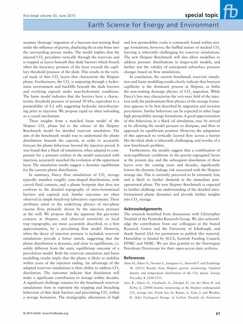
The initial modelling results from the benchmark are based upon calibrated simulations of the uppermost plume layer for the period 1999-2008 (Cavanagh, 2013). The results provide far-field predictions of the trapped CO2 distribution beneath the caprock (Figure 5), and slow dissolution of the CO2 over time (Figure 6), based upon an arrival-rate approximation for ingress at the uppermost layer. The calibrated simulation is compared to the observed spatial distribution for 2008. This allows for an accurate approximation, and forms the basis of the far-field trapping and solubility simulations. The results, described below, have provided further insights relating to CO2 migration and dissolution. Not least, how to effectively model layered gravity segregation in CO2 storage sites, and how to predict plume extent, distribution and timing, both during and after injection. The benchmark model results also demonstrate the sensitivity of CO2 storage simulations to pressure field artifacts associated with reservoir simulation models of drainage and migration.
Figure 5 A near-equilibrium model for 2008 (sec-ond panel and right section), and the observed CO2 distribution (third panel, and red outlines). This requires the initial simulation (left panel and section) to drift until 2098, allowing pressure to dissipate. The blue-orange spectrum is low-high gas saturation (orange ~ 80% gas); greyscale is dissolved CO2 (black ~5 wt%).
Figure 6 Dissolved CO2 as a percentage of the injected mass (2 Mt) for the cali-brated simulation. Note the high initial dissolution, which is then suppressed to less than 10% of the injected mass at the end of injection. The dissolution contribution doubles within five decades post-injection.

special topic
Earth Science for Energy and Environment
www.firstbreak.org © 2015 EAGE66
first break volume 33, June 2015
simulation to act as a proxy for CO2 dissolution (Duan and Sun, 2003; Hassanzadeh et al., 2008). The model dissolution is in agreement with analytical approximations (Alnes et al., 2011), and shows an interesting long-term stagnation and suppression of dissolution in the thin sand wedge beneath the caprock, as seen in cross-section (Figure 5).
Buoyant capillarity versus viscous flowBoth aspects (buoyant capillary flow and long-term dissolu-tion) are further examined in the new benchmark, with the additional challenge of understanding CO2 migration between layers (Figure 7). A range of scenarios are possible for flow communication across the thick shale barrier, which provides an exemplar for the thinner barriers that lie below. A sensi-tivity analysis of these scenarios for different methodologies (black oil and compositional reservoir simulation, invasion percolation basin modelling) is expected to provide insights into vertical flow across low permeability baffles and bar-riers within storage reservoirs in general. The new Sleipner Benchmark will also help to further develop ideas relating to the apparent need for pressure compensation in Darcy flow reservoir simulations. This has significant implications for all CO2 storage models. Uncalibrated reservoir simulations are likely to (a) over-predict pressure increases within the stor-age site and beyond, i.e. forward models of regional pressure change; (b) poorly predict the plume spatial distribution; and (c) underestimate the rapid stabilisation of plume dynamics after injection. The first two consequences will be detectable in model deviation from observations based on monitoring data during the lifetime of a project. The latter consequence will be significant when anticipating long-term plume behaviour and the transfer of post-operational responsibility, especially where predicated on uncalibrated forward modelling of a storage site prior to injection.
ConclusionTwo very different flow modelling approaches have been applied to the Sleipner CO2 storage site. The basin model
interesting from a flow-dynamics perspective: the gas-water contact is flat, representing a back-filling trap under hydrostatic conditions (Figure 5, right cross-section). The uncompensated model is cone-shaped (Figure 5, left cross-section).
The topographically-sensitive result is an expression of the near-equilibrium condition for a trapped buoyant fluid, and indicative of gravity-segregated flow. The black oil simulations are initially far from equilibrium, displaying a characteristic of CO2 storage models: coning of the injected fluid away from the injection location (Singh et al., 2010; Cavanagh, 2013). This is a common feature of all Darcy flow simulations for CO2 injection into saline formations, and speaks to the underlying dependence on permeability and viscosity-mediated flow in the presence of a non-hydrostatic pressure gradient (Cavanagh, 2013). However, as the pres-sure field decays, the redistribution results in an excellent match (Figure 5). Given the weak pressure field on dis-sipation, and the governing equation dependence on viscous flow, the simulated compensation is slow. For example, the Figure 5 simulation match for 2008 occurs approximately 100 years after injection began, and 90 years after injection ceased, circa 2098. This long compensation period allows the simulation to approach equilibrium.
The outcome is a significant improvement on the initial black oil simulation output and provides a methodology for calibrating the model to observations: the initial pressure field, i.e. the transient increase in pressure due to injec-tion, needs to be compensated for by running the model forward until the overpressure has dissipated and the plume has reached near-stasis. For the benchmark simulation, a compensation period of several decades is necessary. This strongly favors a gravity-segregated/capillary-dominated interpretation of the plume behaviour at a relatively short distance from the injection location.
The simulation also suggests a significant local dis-solution effect within decades (Figure 6). The black oil simulator handles CO2 as ‘gas’ and the formation brine as ‘oil’, allowing for the miscibility of gas in oil in the reservoir
Figure 7 (a) a conceptual figure of Darcy-mediated viscous flow for the upper two layers; (b) the corresponding conceptual figure for capillary-mediated gravity-dominated flow; (c) the new Sleipner Benchmark in cross-section, with the Sand Wedge separated from the underlying Utsira Formation by a thick shale. A successful match for the observed distribution of CO2 for layers 8 and 9 from 1999-2008 is the new challenge.
special topic
Earth Science for Energy and Environment
© 2015 EAGE www.firstbreak.org 67
first break volume 33, June 2015
and low permeability rocks is commonly found within stor-age formations; however, the baffled nature of stacked CO2 layering is inherently challenging for reservoir simulations. The new Sleipner Benchmark will also allow modellers to address pressure distributions in larger-scale models, and further test the validity of anticipated subsurface pressure changes based on flow simulations.
In conclusion, the current benchmark reservoir simula-tion and basin modelling results clearly indicate that buoyant capillarity is the dominant process at Sleipner, as befits the non-wetting drainage physics of CO2 migration. While Darcy’s law may characterize the very-near field of the injec-tion well, the predominant flow physics of the storage forma-tion appears to be best described by migration and invasion percolation. Similar behaviour can be expected in other large high permeability storage formations. A good approximation of this behaviour, in a black oil simulation, may be arrived at by allowing the model pressure to dissipate, and flow to approach its equilibrium position. However, the adaptation of this approach to vertically layered flow across a barrier like the thick shale is inherently challenging, and worthy of a new benchmark problem.
Furthermore, the models suggest that a combination of near-equilibrium conditions in the gravity-segregated layers at the present day, and the subsequent dissolution of these layers over the coming years and decades, significantly lowers the dynamic leakage risk associated with the Sleipner storage site. This is currently perceived to be extremely low, and is likely to further diminish in the immediate post-operational phase. The new Sleipner Benchmark is expected to further challenge our understanding of the detailed intra-formational plume dynamics and provide further insights into CO2 storage.
AcknowledgementsThe research benefited from discussions with Christopher Neufeld of the Permedia Research Group. We also acknowl-edge the contribution from our colleagues at the Statoil Research Centre and the University of Edinburgh, and thank Statoil ASA for permission to publish this material. Haszeldine is funded by SCCS, Scottish Funding Council, EPSRC and NERC. We are also grateful to the Norwegian Petroleum Directorate for their open-access data archives.
ReferencesAlnes H., Eiken O., Nooner S., Sasagawa G., Stenvold T. and Zumberge
M. [2011] Results from Sleipner gravity monitoring: Updated
density and temperature distribution of the CO2 plume. Energy
Procedia, 4, 5504-5511.
Arts, R., Eiken, O., Chadwick, A., Zweigel, P., van der Meer, B. and
Kirby, G. [2004] Seismic monitoring at the Sleipner underground
CO2 storage site, North Sea. In: Baines, S., Gale, J. and Worden,
R. (Eds) Geological Storage of Carbon Dioxide for Emissions
assumes ‘drainage’ migration of a buoyant non-wetting fluid under the influence of gravity, displacing the in situ brine into the surrounding porous media. The model implies that the injected CO2 percolates vertically through the reservoir, and is trapped as layers beneath thin shale barriers which breach when the buoyancy pressure of the layer exceeds the capil-lary threshold pressure of the shale. This results in the verti-cal stack of thin CO2 layers that characterize the Sleipner plume. Furthermore, the CO2 is migrating through a hydro-static environment and backfills beneath the shale barriers and overlying caprock under near-hydrostatic conditions. The basin model indicates that the barriers have a charac-teristic threshold pressure of around 50 kPa, equivalent to a permeability of 0.2 mD, suggesting hydraulic microfractur-ing prior to injection. We propose rapid ice sheet unloading as a causal mechanism.
These insights from a matched basin model of the Sleipner CO2 plume led to the release of the Sleipner Benchmark model for detailed reservoir simulation. The aim of the benchmark model was to understand the plume distribution beneath the caprock, in order to accurately forecast the plume behaviour beyond the injection period. It was found that a black oil simulation, when adapted to com-pensate for a pressure artifact in the model associated with injection, accurately matched the evolution of the uppermost layer. The simulation results suggest a dynamic equilibrium for the current plume distribution.
In summary, Darcy flow simulations of CO2 storage typically manifest roughly cone-shaped distributions, with curved fluid contacts, and a plume footprint that does not conform to the detailed topography of intra-formational barriers and caprock seal. Similar outcomes are often observed in simple bench-top laboratory experiments. These attributes attest to the underlying physics of two-phase viscous flow, primarily driven by the injection pressure at the well. We propose that the apparent flat gas-water contacts at Sleipner, and observed sensitivity to local trap topography, are more accurately described, to a first approximation, by a percolating flow model. However, when the decay of injection pressure is included, reservoir simulations provide a better match, suggesting that the plume distribution is dynamic, and close to equilibrium, i.e. subtly different from the static equilibrium outcome of a percolation model. Both the reservoir simulation and basin modelling results imply that the plume is likely to stabilize within years of the injection ending. An advantage of the adapted reservoir simulations is their ability to address CO2 dissolution. The outcomes indicate that dissolution will make a significant contribution to storage within decades. A significant challenge remains for the benchmark reservoir simulations: how to represent the trapping and breaching behaviour of thin shale barriers and percolating CO2 within a storage formation. The stratigraphic alternation of high

special topic
Earth Science for Energy and Environment
www.firstbreak.org © 2015 EAGE68
first break volume 33, June 2015
Hermanrud, C., Andresen, T., Eiken, O., Hansen, H., Janbu, A.,
Lippard, J., Bolås, H.N., Simmenes, T.H., Teige, G.M.G. and
Østmo, S. [2009] Storage of CO2 in saline aquifers – lessons learned
from 10 years of injection into the Utsira Formation in the Sleipner
area. Energy Procedia, 1, 1997–2204.
Nilsen, H.M., Herrera, P.A., Ashraf, M., Ligaarden, I., Iding, M.,
Hermanrud, C., Lie, K.-A., Nordbotten, J.M., Dahle, H.K. and
Keilegavlen, E. [2011] Field-case simulation of CO2 plume migration
using vertical-equilibrium models, Energy Procedia, 4, 3801–3808.
Singh, V.P., Cavanagh, A.J, Hansen, H., Nazarian, B., Iding, M. and
Ringrose, P.S. [2010] Reservoir Modeling of CO2 plume behavior
calibrated against monitoring data From Sleipner, Norway. SPE
134891, 19.
Springer N. and Lindgren, H. [2006] Caprock properties of the
Nordland Shale recovered from the 15/9-A-11 well, the Sleipner
area. In: GHGT-8: 8th International Conference on Greenhouse
Gas Control Technologies, Trondheim, Norway, June 19–22.
Elsevier, Oxford, 6.
Zweigel, P., Arts, R., Lothe, A.E. and Lindeberg, E.B.G. [2004]
Reservoir geology of the Utsira Formation at the first industrial-
scale underground CO2 storage site (Sleipner area, North Sea). In:
Baines, S.J., Worden, R.H. (Eds.) Geological Storage of Carbon
Dioxide. Geological Society, London, Special Publications, 233,
165–180.
Reduction. Geological Society, London, Special Publications, 181-
191.
Bickle, M., Chadwick, R.A., Huppert, H.E., Hallworth, M. and Lyle, S.
[2007] Modelling CO2 accumulation at Sleipner: implications for
underground carbon storage. Earth and Planetary Science Letters,
255, 164–176.
Boait, F.C., White, N.J., Bickle, M.J., Chadwick, R.A., Neufeld, J.A.
and Huppert, H.E. [2012] Spatial and temporal evolution of
injected CO2 at the Sleipner Field, North Sea. Journal of Geophysical
Research, 117, 21.
Carruthers, D.J. [2003] Modelling of secondary petroleum migra-
tion using invasion percolation techniques. In: Duppenbecker, S.
and Marzi, R. (Eds.) Multidimensional Basin Modelling, AAPG
Datapages Discovery Series, 7, 21–37.
Cavanagh, A.J. [2013] Benchmark calibration and prediction of the
Sleipner CO2 plume from 2006 to 2012. Energy Procedia, 37,
3529–3545.
Cavanagh, A.J. and Haszeldine, R.S. [2014] The Sleipner storage site:
Capillary flow modeling of a layered CO2 plume requires fractured
shale barriers within the Utsira Formation. International Journal of
Greenhouse Gas Control, 21, 101-112.
Cavanagh, A.J. and Nazarian, B. [2014] A new and extended Sleipner
Benchmark model for CO2 storage simulations in the Utsira
Formation. Energy Procedia, 63, 2831-2835.
Chadwick, R.A., Noy, D., Lindeberg, E., Arts, R., Eiken, O. and
Williams, G. [2006] Calibrating reservoir performance with time-
lapse seismic monitoring and flow simulations of the Sleipner CO2
plume. In: GHGT-8: 8th International Conference on Greenhouse
Gas Control Technologies, Trondheim, Norway, June 19–22.
Elsevier, Oxford, 6.
Duan, Z. and Sun, R. [2003]. An improved model calculating CO2
solubility in pure water and aqueous NaCl solutions from 273 to
533 K and from 0 to 2000 bar. Chemical Geology, 193, 257–271.
England, W.A., Mackenzie, A.S., Mann, D.M. and Quigley, T.M. [1987]
The movement and entrapment of petroleum fluids in the subsurface.
Journal of the Geological Society, 144, 327–347.
Gregersen U. and Johannessen, P.N. [2001] Distribution of the Neogene
Utsira Sand and the succeeding deposits in the Viking Graben area,
North Sea. Marine and Petroleum Geology, 24, 591–606.
Harrington, J.F., Noy, D.J., Horseman, S.T. and Birchall, D.J. [2009]
Laboratory study of gas and water flow in the Nordland Shale,
Sleipner, North Sea. In: Grobe, M., Pashin, J., Dodge, R. (Eds.)
Carbon Dioxide Sequestration in Geological Media. State of
the Science: AAPG Studies in Geology, Special Publication of
the American Association of Petroleum Geologists, 59, 521–
543.
Hassanzadeh, H., Pooladi-Darvish, M., Elsharkawy, A.M., Keith, D. and
Leonenko, Y. [2008] Predicting PVT data for CO2-brine mixtures
for black-oil simulation of CO2 storage. International Journal of
Greenhouse Gas Control, 2, 65–77.
Hellevang, H. [2006] Interactions between CO2, saline water and
minerals during geological storage of CO2. Ph.D. Thesis, University
of Bergen, 38.
Complete Solution for Aeromagnetic Surveys
��&RPSUHKHQVLYH�DQG�Á�H[LEOH�'$6����LVRODWHG�56����FKDQQHOV����*ESV�(WKHUQHW�����DQDORJ�LQSXWV�����ELW���(PEHGGHG�*36�UHFHLYHU��8S�WR���PDJQHWRPHWHUV��/HVV�WKDQ�����S7�LQWHUQDO�QRLVH��6DPSOLQJ�UDWH�RYHU��N+]��3URYHQ��H[WUHPHO\�UREXVW�FRPSHQVDWLRQ�DOJRULWKPV��$GDSWLYH�VLJQDO�SURFHVVLQJ�WHFKQLTXHV1(:��'\QDPLF�FRPSHQVDWLRQ�RI�RQ�ERDUG� HOHFWURQLF�V\VWHPV
2nd Generation DAARC500
DAARC500Data Acquisition &
Adaptive AeromagneticReal-Time Compensation
RMS Instruments Mississauga, Ontario, Canada
www.rmsinst.com
RMS ad 0113s.indd 1 1/7/13 7:43:10 PM
CC02537-MA004 RMS.indd 1 12-02-13 17:36