the mod-2wind turbine development project - nasa · the mod-2wind turbine development project ......
TRANSCRIPT
OOEINASA/20305-5NASA TM-82681
The Mod-2 Wind Turbine Development Project
(NASA-T_-_2681) _L MOO-2 _&ND _URBI_E B81-2"/..606DEVELOPMENT pROJEC_ _£na£ _epo_t (NASa)
2_ p HC AO2/_F A01 CSCL 10B gnc£asG3/qq 26883
Bradford S. LinscottNational Aeronautics and Space AdministrationLewis Research Center
Joann T. DennettRdd Consultants Inc.
and
Larry H. GordonNational Aeronautics and Space AdministrationLewis Research Center
July 1981
Prepared for jlU.S. DEPARTMENTOF ENERGY
. Conservationand RenewableEnergy 1Divisionof Wind EnergySystems
1981019068
https://ntrs.nasa.gov/search.jsp?R=19810019068 2018-06-13T11:10:22+00:00Z
,L
"" DOEINASAI20305-5- NASA TM-82681
i
_ The Mod.2 Wind Turbine Development Project
L Bradford S. Linscott, National Aeronautics and Space Administration; Lewis Research Center
Cleveland, Ohio 44135
Joann T. DennettRdd Consultants Inc.Boulder, Colorado 80303and
Larry H. GordonNational Aeronautics and Space AdministrationLewis Research CenterCleveland, Ohio 44135
July 1981
Work performed forU,S. DEPARTMENTOF ENERGYConservation and Renewable EnergyDivision of Wind Energy SystemsWashington, D.C. 20545Under Interagency Agreement DE-AI01-79ET20305
1981019068-TSA03
:: IntroducUon blade, Is pitchedto controlrotorspeedand power.This designfeature reducesrotor weightand cost
People have used the wind for a millenniumto with only minorcompromisesin power outputarid;'_'- pump water, grind grain, and sail ships. More startup and shutdowncontrol, Second, a lighter,': recently, peoplehave been using wind to produce more flexible tubular tower replaces the heavier;,_ electricity, trusstowersthatwere usedfor thefirst DOE/NASA_,_ wind turbines.A lighter, more compact eplcycllc
.!. Years ago, interest flourished In developing gearbox located in the nacelle further reduceslarge wlnd_Iriven electric generating systems, costs when compared with the parallel shaft
_ However, Interest In such systems derlinedbecause they were not cost competitive with gearboxes used on the earlier DOE/NASA wind
i_ systems using fossil fuels. Growing energy turbines. Finally, by allowing the rotor blades torequirements,increasingfuel costs,declining fuel teeter at the hub in response to wind forces, incontrastto rotorblades rigidlyattachedto thehub,
:. reserves, and Dependenceon foreign sources is the Loadson all componentsere diminished,changingsubstantiallythiseconomic picture.
The primary objective i:; the developmentof The Bureau of Reclamation within theDepartment of the Interior has developed a, Mad-2 was to design a wind turbine to produce concept for the integrationof large clusters of
energyfor less than 5C/kWhbased on 1980 cost wind-turbinegeneratorswith existinghydroelectricforecasts.The pricingmethod used to project the power systems, The technical and economicMad-2 energycosts is the levelized, fixed-charge- feasibilityof this concept will be evaluatedby therate approach,generally accepted in the electric installation and operation o! two different windutility industryas a basis for relative ranking of turbines. Each wind turbine, called a Systemsenergy alternatives. This method derives a Verification Unit (SVU), will be installedat the sitelevelized energy price necessary to recover the of a potential cluster of wind turbines,One suchutility's purchasing, installing, owning, operating, site Is located approximately5 miles southwestofand maintenancecosts. Medicine BOw,Wyoming.The SVU wind turbines
will be placed about 3000 ft apart and arescheduled to start checkout operations in late
The Faders!Wind Energy Program _981. The Bureau of Reclamation awarded a--
TheU.S. Departmentof Energy(DOE) hasspent contractto HamiltonStandardto design,fabricate,about $200 millionon wind turbine researchand Install, and check out a wind turbine called thedevelopment.Known as the Federal Wind Energy WTS-4 SVU machine. The WTS-4 has a 256-ft-
diameter rotor,supportedon a tubularsteel towerProgram, its purpose is to develOp small,intermediate, and large.scale wind turbines to that locates the center of the rotor 262 ft above
ground. With a wind speed of 36 mph at 262 ttharnessthe wind ina costeffective way, Thiswindturbinedevelopmenteffort includesconstructionof above ground, the WTS-4, produces 4 MW ofseveral intermediateandlarge-scalewindturbines power. Inaddition,NASAawardeda contractto theat utilitysites and experimental testing of these Boeing Engineering and Construction Co. tofabricate a Mad-2 SVU machine and install themachineson utilitynetworks. Mad-2 near Medicine Bow.The Mad-2 SVU will be
The Mad-2 wind turbine, e second generation identicalto the three machines inStafled.byBoeingmachine,is the latestdevelopmentin the prOgram and now operatingnear GoodnoeHills.conductedjointlyby theU.S. Departmentof Energy(DOE) and the Lewis Research Center of theNational Aeronautics and Space Administration
(NASA).Mad-2,designed,built,andinstalledby the First Generation Wind TurbinesBoeing Engineeringand ConstructionCo,, is theculmination of a technology el|oft to attain a The first experimental wind turbine, calledmachine thal has high potential for commercial Mad-0, started operation In September 1975.production. In addition, Mad-2, when produced In Mad-0 hasa rotord(ameterof 125ft, generates100quantitiesof 100 or more, can generate electrical kW of electricityin an 18 mphwind, and is locatedenergy at a cost very close to the current cost of at NASA's Plum BrookStation in Sandusky,Ohio.fossil-fuelgeneratedelectricity.The first clusterof This machine was designed as an experimentalthree Mad-2 wind turbines,located near Goodnoe lest bed. Mad-0 was first used to validate theHills, Washington,is now producingpower for the accuracy of analytical design methods, It is nowBonnevillePowerAdm!nistration. used to test new wind t{frbineconfigurations.For
Four significant design features account for example, the Med-Oconfigurationwas changed to =Mod-2's major cost-of-electricityadvantage over simulate the teetered rotor and the flexibletower, jthe earlier Mad-0, Mod-0A, and Mad-1 first- when Mad-2 was first being designed. Mad-0 was Igenerationresearchmachines.First,onlythe45-ft- tested to explore the performance Of these twolong blade tip, rather than the entire 150-ft-long design features.Resultsof these tests were used
by the Boeing Engineeringand ConstructionCo. General Electric Space Division surveyed theand incorporated into the final MOd-2dee}an, nation for good wind turbine sites--those with
Four MOd-0Amachineswere built to gain early strong,steadywinds (averaging 11 to 14 mph). Itexperience with wind turbinesconnected to and found many regions with winds averaging moreoperaledby utility companies.Althoughsimilar to than 14 mph(fig. 2).the Meal-0,the Mod-OAhas a larger gearboxand Wind turbines require a minimum 10-mph
.. generator,wltloh allowsgenerationof upto 200 kW average wind for efficient electricity production.- in a 22-mph wind speed. The llrst machine began Estimates basing wind power production on.. operation in Clayton, New Mexico, In November average annualwind speedsmay be conservative
1977. InJune1978 a sistermachinewas startedon since power productionvarieswiththe cube of thethe island of Culebra, off Puerto Rico. Another wind speed, and. since power output Increases
r " islandsite, Block Island. Rhode Island, received its dramatically with high gusts. Once general areasMod.OAwindturbinegeneratedpowerin May t 979. are established,it will be necessary to detail theThe fourth MOd-OA wind turbine started utility wind resourcesavailableat specific sites.operationon the island el Oahu, Hawaii, in June1980. The Clayton and Block Island machinesprovide electricity to relatively small-scale utility Wind Turbine Economicsnetworks. The Mod,0A's locatedat Culebra,PuertoRico, and Oahu, Hawaii. however, joined larger Table f details the cost of energyproduced byutility networks. The Westinghouse Electric Mod-2. The cost of wind-generatedelectricity willCOrporation installed the Culebra machine and decrease as more machinesare produced. Figureassembled, tested, and installed both the Block 3 cites economies of sca}e for the early machines.Island and Oahu machines. Westinghouse Estimatesof the t00th productionunitcostsfor thepresentlyperforms nonroutinemaintenanceon all MOd 2 are summarized In table 2. These costsof the DOE/NASAMOd-0Amachines.The valuable assumeexperience gained during early operation el the * - Mid-1980 dollarsClayton and Culebra MOd-0A machines was • A25-unit wlndclusterfactored into the final designof the MOd-2. • A rate of installationof one machine per
In 1979, the first experimental multimegawatt monthmachine, the MOd-1,began operationfor the Blue • Generally flat sites with few naturalRidge Electric Membership Corporation at obstaclesHoward's Knob, near Boone,North Carolina. With • Soil easily prepared for foundationa rotor diameter of 200 It, it was the world's largest • Land cost not includedexperimentalwind machine.Mod-1can produceup • Transportationdistance of 1000 milesto 2 M.Wel electricityina 26 mph wind. The Mod-twind turbine was designed, fabricated, and TABLE I.QCOSTOF ELECTRICITYinstalled by the General Electric Co.. forDOE/NASA. Near the end of the Mod-t design 'rho cost el electrmdy Is a function ot the turnkey cost
analysis, annull energy prOduction, and COSt el operation ._ndeffort, General Electricconducteda studytodefine maintenancea wind turbine that was more advanced than ICxFCR*AOMMod-t. The study, which came to be called Mod- coE AEP 4l¢'kWh1A, identified innovativedesign features, includingthe pitchable blade tip rotorand the tubular tower. _cR 18%peryear tevehzed,fixed ohar0erate
Includtn 0 return on Capital. Inccm@This studyled to the tests conductedon Mod.Oand ta_.PtOpOltVlax,andInsuranceassistedthe BoeingEngineeringand Construction FCR is sensdwe to the cost of
CO. during its design of Meal-2. Experimental cap,tel,cap,tahzahortmethod.,,1come tax tale. and systemperformance tests were conducted on the Mod-1 _,_,,hme
wind turbine.Resultsof these tests are nowbeing ,c $2.1_,o.0¢_ ,_dial(turnkpytcostcdtheone,gy=--: used to assist designers in defining wind turbines s_stemincludingcompletecost
even more advanced than MOd-2. ,,.t_osuroIo the ut,llty f(,tpgt£hll$1n_, mStallJlt_. _nd -'.oltmgUp lOgiStics for Ih_ Onelg',production system
--: U.S.Wind Resources .o,, .°,,,,.,o..,.,,o°..dIO&MI cost including operating
Erwironmental. economic, and meteorological budQelsandmaintenancebudgelsresearch is keeping pace with hardware Ate, 975. ItP arlt,c,pated _nnual enelgydevelopmentin the FederalWind EnergyProgram. _,,,,,J,,ct,,,,,,,_t_, ,_ne,ov_,s_em,_,FO,example, appropriatesite selectionisessential _,wh AEPtakes inlo acc¢)untpnpr_y |It oduc ll()n I I q_ql_Sfor optimal power production Current studies will _rr.h_._,r_,_t_,..n_.,f_,t,,,tv,,_more thoroughly quantify U S wind resources: theenergy_v_.temequ,pmel_tat.1
th_ unav_il._bdd'_ ¢)! the' enetg_however, broad estimates are available (fig t) .,,,,,,,_.{,e.,,,d_
2
1981019068-TSA05
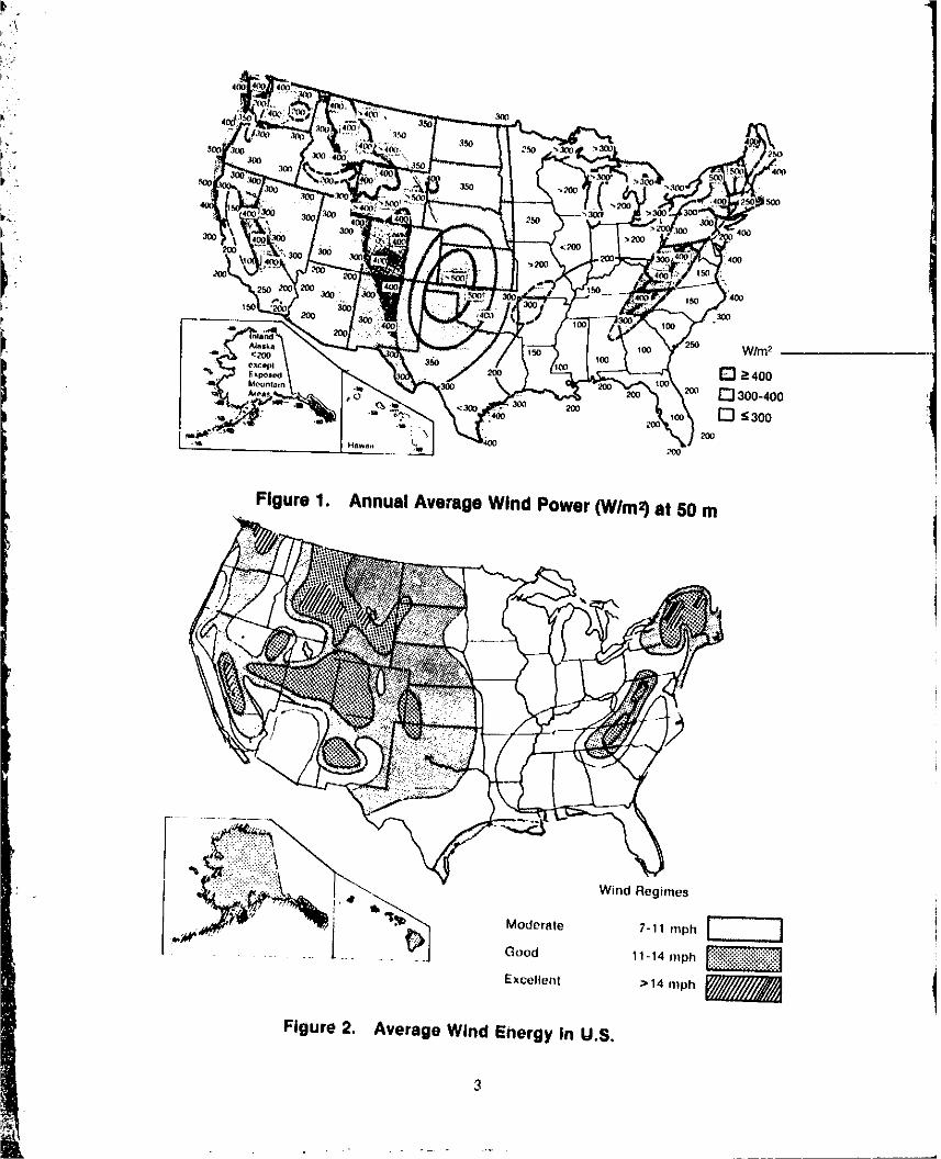
Figure 1. Annual Average Wind Power (WIm2)at 50 m
.. Good 11-14 mph
Excellent >14 mph
Figure 2. Average Wind Energy In U.S.
3
1981019068-TSA06
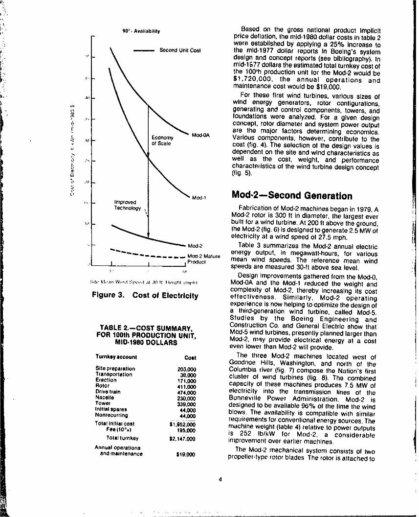
Based on tile gross national product Implicit),- 90".,Availability price deflation, the mld-t980 doUar costs in table 2
were established by applying a 25% Increase to;' _ SecondUnltCost the mid-t977 dollar reports In Boelng's system
F .... "_ design and concept reports (see bibliography). In
i,_ mid-1 £77 dollars the estimated total turnkey cost of
, theO0'hpro.ctonunlttottheMod-2wouldbe
L:' 4. $1,720,000, the annual operations andP.: maintenance cost would be $19,000,
For these first wind turbines, various sizes of_" '" wind energy generators, rotor configurations,
,', generating and control components, towers, and'_, foundations were analyzed. For a given design,_ concept, rotor diameter and system power output
are the major factors determining economics.,_: Mod-0A Various components, however, contribute to the
"; _ ofScale cost (fig. 4). The selection of the design values isu _ dependent on the site and wind characteristics as•_ well as the cost, weight, and performance_ '' _. characteristics of the wind turbine design concept,2 (fig. 5).=
Mod-2--Second Generation('_ Mod,t,., Improved
Technology Fabrication of Mod-2 machines began in 1979. AMod-2 rotor is 300 ft in diameter, the largest ever J
built for a wind turbine. At 200 ft above the ground, jj_" __ the Mod-2 (fig. 6) is designed to generate 2.5 MW of
electricity at a wind speed of 27.5 mph.Meal-2 Table 3 summarizes the Mod-2 annual electric
"'_"_"'_.-_ ..... ,,._,Mocl-2Malure energy output, in megawatt-hours, for various Jmean wind speeds. The reference mean wind |
i ProduclI I speeds are measured 30-ft above sea level. :1;' ;" Design improvements gathered from the Meal-0.
s,t,, u,,,,, w,,,,t :_r,',,,I.a ._t_, n,,,!=n=L,,,rh_ Mod-OA and the Mod-1 reduced the weight andcomplexity of Mod-2, thereby increasing its cost
Figure 3. Cost ot Electricity eflectiveness. Similarly, Mod-2 operatingexperience is now helping to optimize the design ofa third-generation wind turbine, called Mod-5.Studies by the Boeing Engineering andConstruction Co. and General Electric show that
TABLE 2.-.COST SUMMARY, Mod-5 wind turbines, presently planned larger thanFOR 100th PRODUCTION UNIT, Meal.2, m=_yprovide electrical energy at a cost
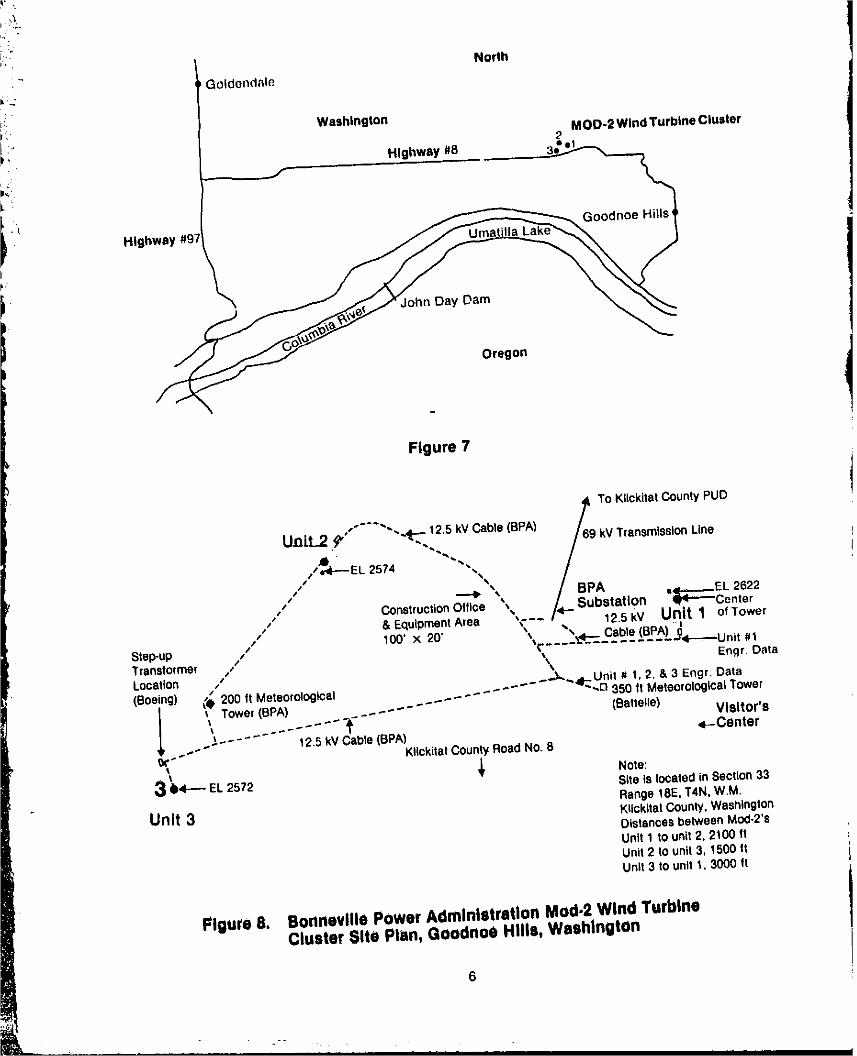
MID.1980 DOLLARS even lower than Mod-2 wiil provide.The three Mod.2 machines located west of
Turnkey account ColtGoodnoe Hills, Washington, and north of the
Sltepreparatlon 203,000 Columbia river (fig. 7) compose the Nation's firstTransportation 36,000 cluster of wind turbines (fig. 8). The combinedErection 171,000 capacity of these machines produces 7.5 MW ofRotor 411,000Dnvetraln 474,000 electricity into the transmisslon lines of theNacelle 230,000 Bonneville Power Administration. Mod-2 isTower 339,000 designed to be available 96% of the time the windInltlalspares 44,000 blows. The availability is compatible with similarNonrecurring ....44,000 requirements for conventional energy sources. TheTotalInitialcost $1,952,000 machine weight (table 4) relative to power outputs
Fee('tO",,) 195,000 is 252 Ib/kW for Mod-2, a considerableTotalturnkey $2,14-?,000 intprovement over earlier machines.
Annualoperations 'The Meal-2 mechanical system consists of twoendmalntenanca $19,000 propeller-type rotor blades The rotor is attached to
1981019068-TSA07
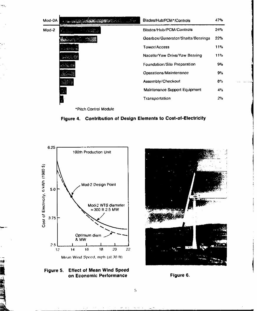
Mod-OA BlodeslHublPCM*lControls 47%
Mod-2 BladeslHub/PCM/Controls 24°,'o
Goarbox/Gonerator/Shalts/Benrings 22%
Tower/Access 11%
Nacelle/Yaw Drive/Yaw Bearing 11%
Foundation/Site Preparation 9%
Operations/Maintenance 9%
Assembly/Checkout 8% ........
B MaintenanceSupportEquipment 4%
a Transportation 2%*Pitch ControlModule
Figure 4. Contribution of DesignElementsto Cost-of-Electricity
Optimumdiam _...-_& MW
25 1 I I I12 14 16 16 20 22
Mt,,m Wind Speed, niph (at 30 ft}
. Figure 5. Effect of Mean Wind Speedon Economic Performance Figure 6.
1981019068-TSA08
w¢ '*
i ¸,
North
•- _Goldendale
i.
:. Washingtonl," MOD-2 Wind Turbine ClusterI, 2
• Hlghway_
-I
J
Oregon
Figure 7
f To Kllekitat County PUD_,,""-'"",,,,_¢._,12.5-, kV Cable (BPA) /69 kV Transmission Line
/t _i_M"EL 2574 _.%% /,./ _ "• / BPA =I..-..-.EL 2622
/ Construction Office ",% /,,t-- Substation i'i----"Center/t & Equ(pment Area _c-" • 12.5 w Unit 1 of Tower
/ 100' X 20' '_,. ",.,=.-..-Cable (BPA) i_Step-up /" '_¢.... ='" ......... "r'i"---'U nit #1Transformer / \ Engr DataLocation ,'
• _.--,_...._,_Unit # t, 2, & 3 Engr. Data(Boeing) _4_200 ft Meteorological - _ ..... _-- _ _ - ...o 350 ft Meteorological Tower
l _ Tower (BPA) . - .... (Battelle)_ ........ - - "_-" Visitor's
.--.-- .... 12.5 kV Cable (BPA) ,i--Center
_- Kllckitat County Road No. 8_, Note:
3 _,i---- EL 2572 Site is Iooated in Section 33
Range 18E, T4N, W.M.Unit 3 Kllckltal County, Washington
Distances between Mod.2's
Unit 1 to unit 2, 2100 ftUnit 2 to unit 3, 1500 ttUnit 3 tOUnit 1. 3000 ft
Figure 8. Bonneville Power Administration Mod,2 Wind TurbineCluster Site Plan, Goodnoe Hills, Washington
_=m_ ,_ 4--
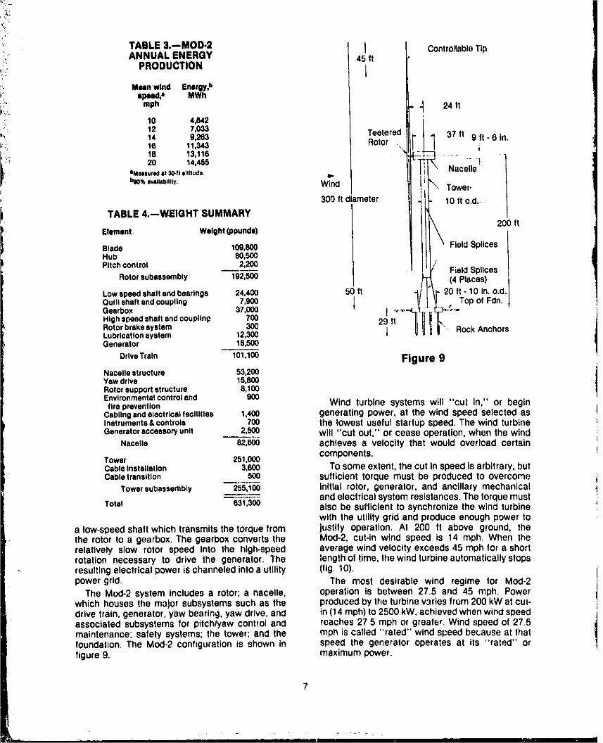
TABLE 3.-,MOD.2 I ControllableTipANNUAL ENERGY 45 fi
_: PRODUCTION 1
Mean wind Energy,b
,, speed,a MWhmph --_ 24 ft
10 4,842
12 7,033 Teetered 37 it 9 ft - 6 In.14 9,263 1, 16 11,343 Rotor t
ii:i 18 13,116 il - -
!i 20 14,455 ! Nacelle
IMMlured it 3o-n iiItlludo.
hi0% Ivlllablllty, Wind Tower.
300 ft diameter 10 it o.d,
TABLE 4.--WEIGHT SUMMARY200 fi
Element Weight (pounds)
Blade 109,800 Field SplicesHub 80,500
Pitch control 2,200 Field SpgcesRotor subassembly 192,500 (4 Places)
Lowspeed shaft and bearings 24,400 50 ft ..,. -1 20 ft - 10 in. o.d.Quill shaft end coupling 7,900 i -- Top of Fdn. t
Gearbox 37,000 _ _ .,_ _.CHigh speed shaft and couplint_ 700 29 ti"Rotor brake system 300Lubrication system 12,300 J • Rock AnchorsGenerator I 8,500
Drive Train 101,100 Figure 9Nacelle structure 53,200 jYaw drive 15,800 1Rotorsupport structure 8,100Environmental controland 900tire prevention Wind turbine systems will "cut In," or begin
Cablingandelectricaitecllltles 1,400 generatingpower, at the wind speed selected asInstruments&controls 700 the lowest useful startupspeed. The wind turbineGeneratoraccessoryunit 2,500 will "Cut Out," or cease operation,when the wind
Nacelle 82,600 achieves a velocity that would overload certain
Tower 251,000 components.Cableinstallation 3,600 TOsomeextent,the cut inspeedisarbitrary,butCabletrensltlon 500 sufficient torque must be produced to overcome
Tower subassembly 255,100 initial rotor, generator, and ancillary mechanicalandelectricalsystemresistances.Thetorquemust
Total 631,300 also be sufficientto synchronizethe wind turbinewith the utilitygrid and produce enoughpower to
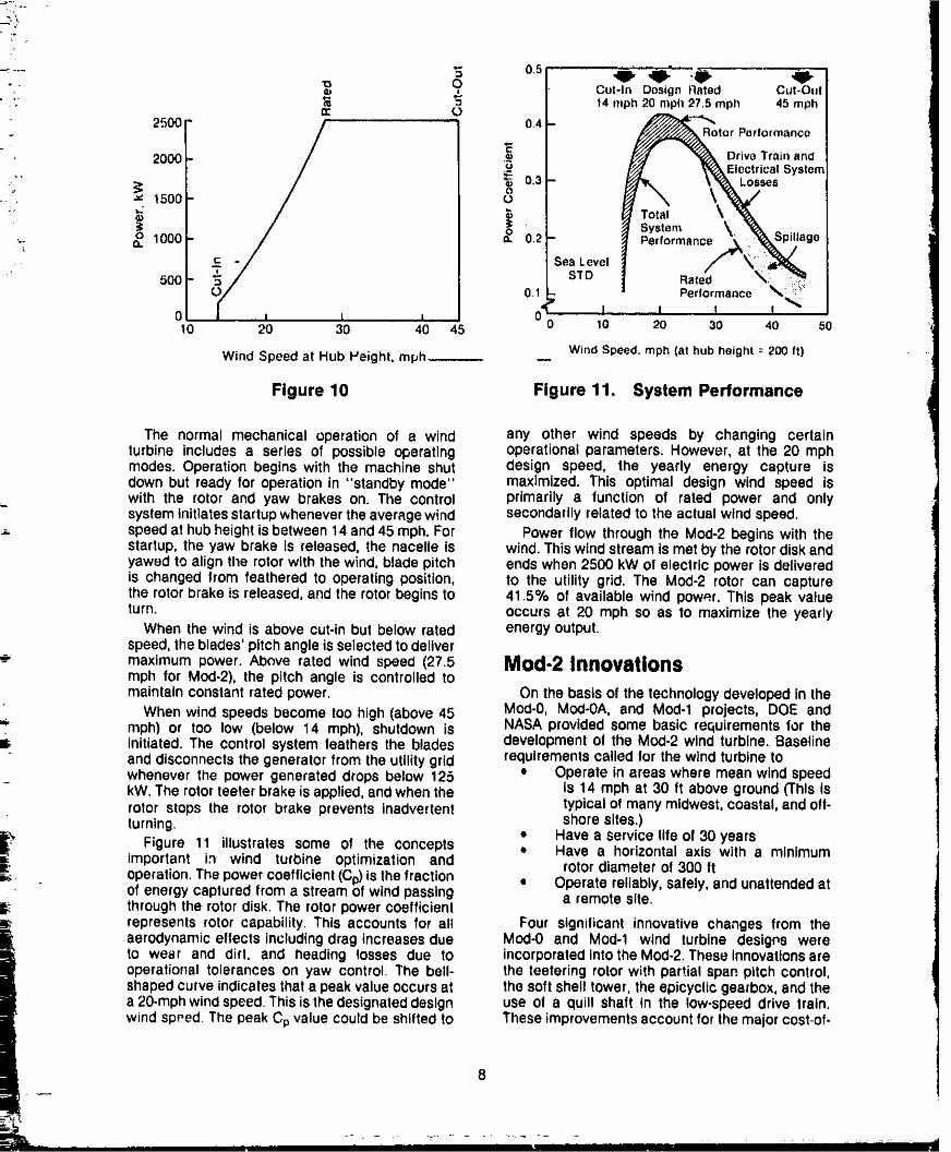
a low-speedshaft whichtransmitsthe torquefrom justify operation, At 200 ft above ground, thethe rotor to a gearbox.The gearbox convertsthe MUd-2, cut-in wind speed is 14 mph. When therelatively slow rotor speed Into the high-speed averagewinclvelocityexceeds45 mph for a shortrotation necessary to drive the generator. The lengthof time,the windturbineautomaticallystopsresultingelectricalpower ischanneledintoa utility (fig. 10).power grid. The most desirable wind regime for Mud-2
The MUd-2 system includesa rotor; a nacelle, operation is between 27.5 and 45 mph. Powerwhich housesthe major subsystemssuch as the producedbythe turbinevariesfrom 200 kWat cut-drive train, generator,yaw bearing,yaw drive,and in(14 mph)to 2500 kW,achievedwhenwindspeedassociatedsubsystemsfor pitch/yaw control and reaches 27 5 mph or greater.Wind speed of 27.5maintenance; safely systems; the tower; and the mph is called "rated" windspeedbecauseat thatfoundation.The MUd-2 configurationis shown in speed the generator operates at its "rated" orfigure9. maximumbower.
7
1981019068-TSA10
41/ -O" ,W-"o_ O Cut-In Design Rated Cut-eel
• ; _ "_ 14 mph 20 mph 27.5 mph 45 mph¢ O
2500 0.4 _--¢_Rotor Performance
"_ _" _ DriveTrainand2000 ._.u r _,Eloct rieal Systen
_* _ 0.3 _ _ .'_,ea" _ 1500 o
" System \- Performance _' Spillage
. ,-, 1000 o 0.2 _eiformance & '_P_la. c - ;ea Level
500 " STD .O.1 Per formsr_co
0 I t I I I10 20 30 40 45 10 20 30 40 50
Wind Speed. mph tat hub height -- 200 ft)Wind Speed at Hub Weight, mph__
Figure 10 Figure 11. System Performance
The normal mechanical operation of a wind any other wind speeds by changing certainturbine includes a series of possible operating operational parameters. However, at the 20 mphmodes. Operation begins with the machine shut design speed, the yearly energy capture isdown but ready for operation in "standby mode" maximized• This optimal design wind speed iswith the rotor and yaw brakes on. Tl_e cOntrol primarily a function of rated power and onlysystem initiates startup whenever the average wind secondarily related to the actual wind speed.speed at hub height is between 14 and 45 mph. For Power flow through the Meal-2 begins with thestartup, the yaw brake is released, the nacelle is wind. This wind stream is met by the rotor disk andyawed to align file rotor with the wind, blade pitch ends when 2500 kW of electric power is deliveredis changed from feathered to operating position, to the utility grid. The Mod-2 rotor can capturethe rotor brake is released, and the rotor begins to 41.5% of available wind power. This peak valueturn. occurs at 20 mph so as to maximize the yearly
When the wind is above cut-in but below rated energy output.speed, the blades' pitch angle is selected to delivermaximum power. Above rated wind speed (27.5 aod-2 Innovationsmph for Mod-2), the pitch angle is controlled tomaintain constant rated power. On the basis of the technology developed in the
When wind speeds become too high (above 45 Meal.0, Mod-OA, and Mod°l projects, DOE andmph) or too low (below 14 mph), shutdown is NASA provided some basic requirements for the
B. initiated. The control system feathers the blades development of the Mod.2 wind turbine, Baselineand disconnects the generator from the utility grid reclulrements called for the wind turbine towhenever the power generated drops below 125 • Operate in areas where mean wind speedkW. The rotor teeter brake is applied, and when the is 14 mph at 30 ft above ground ('rhis isrotor stops the rotor brake prevents inadvertent typical of many midwest, coastal, and off-turning, shore sites.)
Figure 11 illustrates some of the concepts • Have a service life of 30 years0¢ important in wind turbine optimization and • Have a horizontal axis with a minimumrotor diameler of 300 tt,_ operation. The power coefficient (Cp) is the fraction • Operate reliably, safely, and unattended at
of energy captured from a stream of wind passing a remote site.through the rotor disk. The rotor power coefficient
_- represents rotor capability. This accounts for all Four significant innovative changes from theaerodynamic effects including drag increases due Meal-0 and Meal-1 wind turbine desigps wereto wear and dirt, and heading losses due to incorporated intothe Mod-2. These innovations areoperational tolerances on yaw control. The bell- the teetering rotor with partial span pitch control,shaped curve indicates that a peak value occurs at the soft shell tower, the epicyclic gearbox, and thea 20-mph wind speed. This is the designated design use of a quill shaft in the low-speed drive Irain.wind speed The peak Cp value could be shifted to These improvements account for the major cost.of-
8
1981019068-TSA11
electricity advantageover competingwindturbine Quill Shift
•: systems. This shaftdesignreducesthe two-per-revolutionrotor torque oscillationsthat can be pronounced
Upwind Teetering Rotor with Partial Span and troublesome,The quill shaft Is flexible andPitch Control reduces these oscillations,reducing the fatigue
effects at the gearbox and the possibility ofThe rotor Is a two-bladedsteel, teetering type desynchronlzatlonwith the utilitygrid.
with partial apen pitchcontrol,Orientingthe rotorupwindreducesrotorfatigueslightlyand Increases Although less significant, two other changes
from previous designs were also made. Theannual power production by 2.5%, The rotormicroprocessorcontrol system is located in the
converts up to 41.5% of the wind power to nacelle rather than on the ground in the tower's•, rotational electrical generating power, Adverse base. This proved less costly and reduced• impactsof the upwindrotoron theyaw systemare antlclpeted maintenance costs. Field assembly
i minimizedbythe teeteringmechanism, costs were also diminishedby Installinggin polehoist and guy line foundationsat each site, Thispermitsuse of less expensiveginpolesand hoists
i-. Sott Shell Tower rather than a cumbersome crane to erect theThe tower is fabricated using manufacturing turbine. Thus, field installation efficiency was
techniquesdevelopedfor utilitycantilever power increased.poles,
A soft shell towerhas advantagesover the stiff- Components of the Mod.2truss towerpreviouslyused.Thesoft towerweighs Mechanical Systemmuch less, the shell type of constructionis lessexpensive to fabricate, and the tower design Rotorreduces vibration problems throughoutthe windturbinesystem.A dynamicallysoft rather thanstiff The identifyingsilhouetteof thewind turbine,thetoweralsopermitstheuseel heavybuteconomical rotor,has three majorparts: the blades,the pitch-and reliablerotordesigns, changemechanism,and the hub.
Dynamically solt towers have a lower natural Blade.--The blades of the Mod-2 3O0-ft-frequency of vibration than the blade passing diameter rotor are hollowsteel shellconstructionfrequency while a stiff tower has a higher with steel spar members, The blades havefrequency.The softtower is therefore less likelyto continuousconstructionthrough the hub, whichreinforcevibrationsestablishedby the rotationof greatly increases their strengthand resistancetothe rotor.Consequentlythe effects of fatigueand fatigue. The steel blades are imperviousto dust,extraneousmotiononthe driveassemblyandother rain, and lightningand resist handling damagesubsyster_ _rA rArl_=d during transportand erection.
The rotor is oriented upwind to reduce theproblems previously encountered with "towershadow," a pulse induced by the sudden, sharp
Three,Stage Eplcy¢ll¢ Gearbox reductionin windvelocityas downwindrotorspassThewind turbinesystemis designedso that the behind the tower, This cyclic pulsing increases
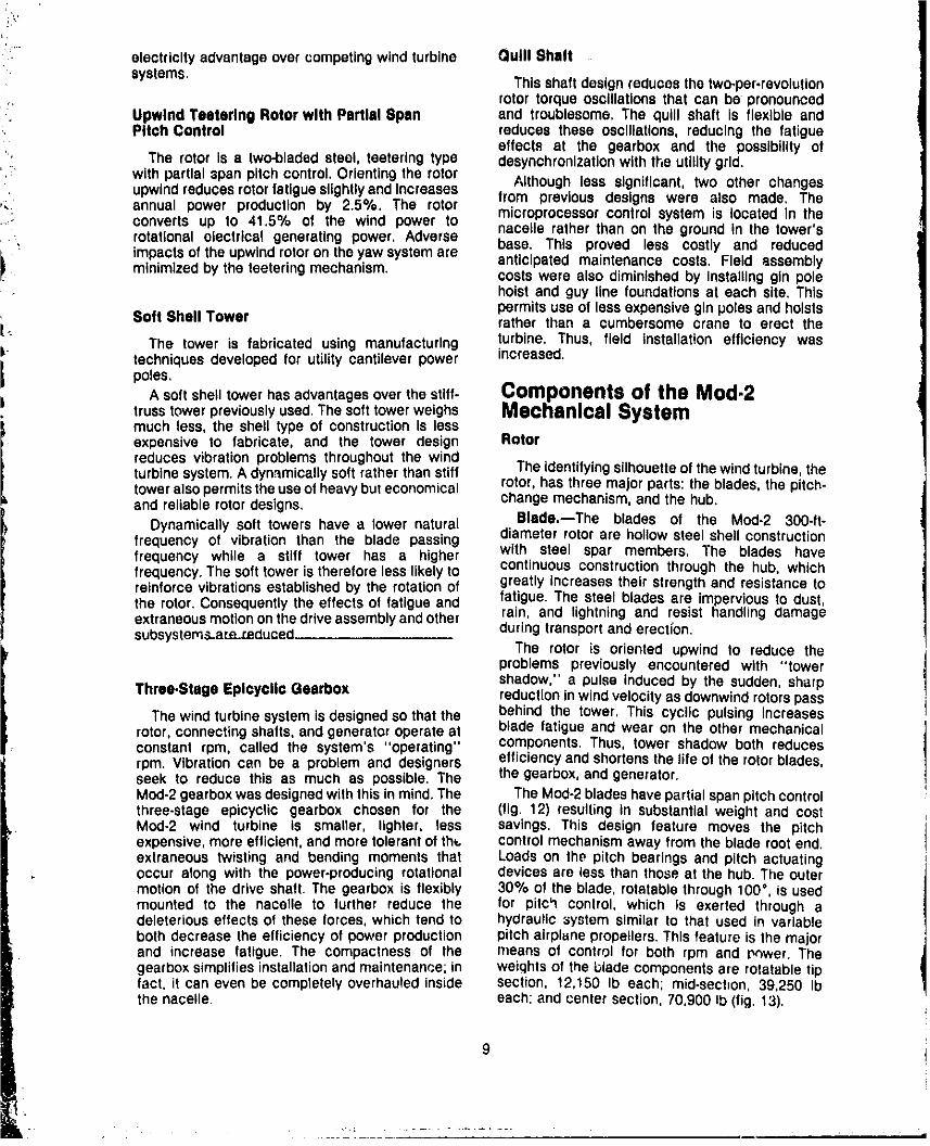
rotor,connectingshafts,and generatoroperate at blade fatigue and wear on the other mechanicalconstant rpm, called the system's "operating" components. Thus, tower shadow both reducesrpm. Vibration can be a problem and designers elficiency and shortensthe life of the rotorblades,seek to reduce this as much as possible. The the gearbox,andgenerator.Mad-2gearboxwasdesignedwiththis in mind.The The Mod-2bladeshavepartialspanpitchcontrolthree-stage epicyclic gearbox chosen for the (fig. 12) resultingin substantialweight and costMeal*2 wind turbine is smaller, lighter, less savings. This design feature moves the pitchexpensive,more efficient,and more tolerantof the. controlmechanismaway from the blade rootend.extraneous twisting and bending moments that Loads on the pitch bearingsand pitch actuatingoccur along with the power-producingrotational devicesare less than those at the hub. The outermotionof the drive shaft. The gearboxis flexibly 30% of the blade, rotatable through100°, is usedmounted to the nacelle to further reduce the for pitch control, which is exerted through adeleteriouseffects of these forces, which tend to hydraulic _ystem similar to that used in variablebothdecrease the efficiencyof power production pitch airplunepropellers.This feature is the majorand increase latlgue. The compactness of the means of control for both rpm and P_wer. Thegearboxsimplifiesinstallationandmaintenance;in weights of the blade componentsare rOtatabletipfact, it can even be completelyoverhauledinside section, 12,150 Ib each; mid-sect=on,39,250 Ibthe nacelle, each: and center section,70,900 Ib (fig. 13),
1981019068-TSA12
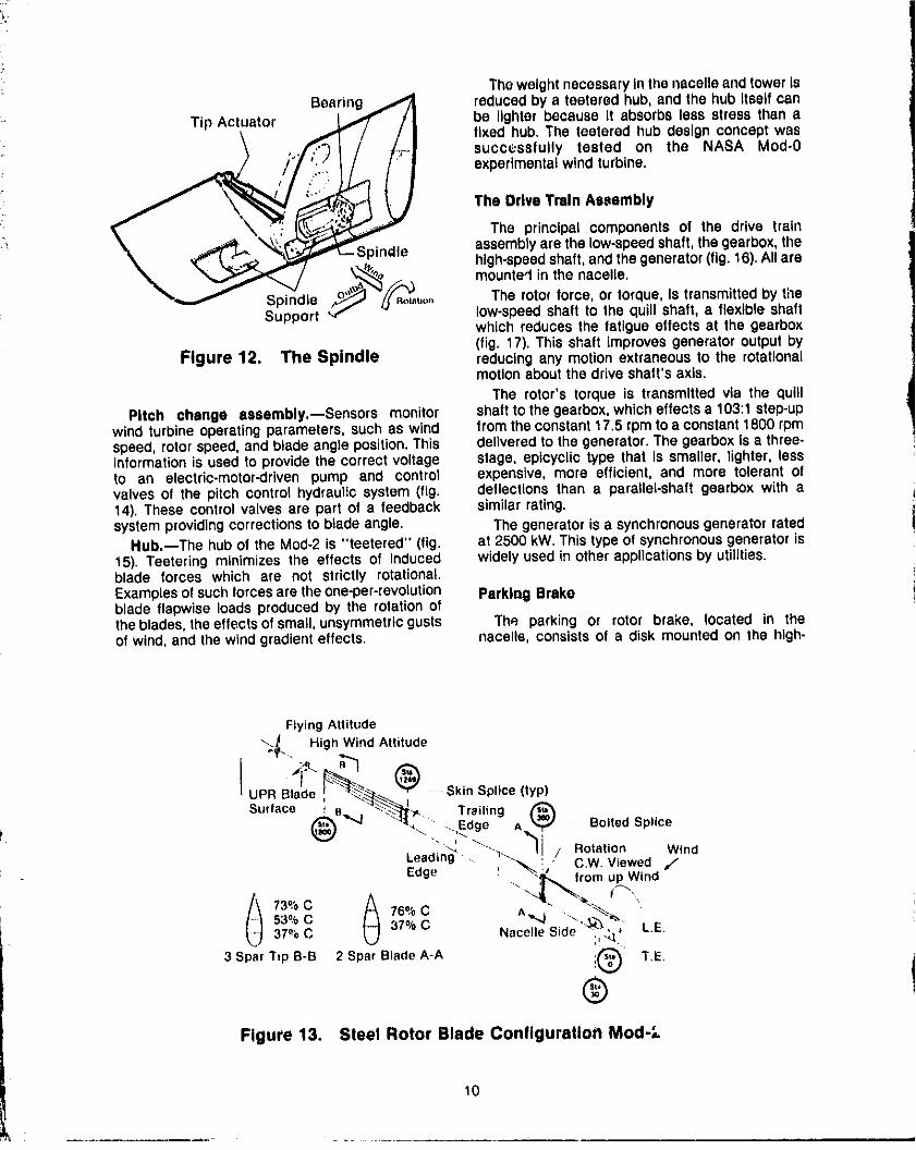
Theweightnecessaryinthenacelleandtower IsBearing _,_ reducedby a teetered hub, and the hub Itselfcan
Tip Actuator ,. _ /| be lighter because it absorbsless stress than a
fixed hub. The teetered hub design concept was
successfully tested on the NASA Mod-0experimentalwind turbine.
The Drive Train Assembly
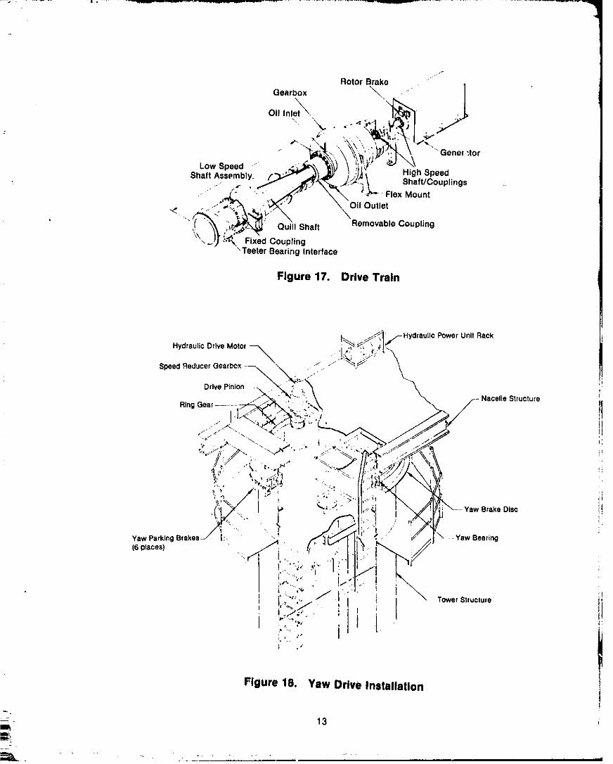
The principal components of the drive trainassemblyare the low-speedshaft,thegearbox,the
__ Spindle high-speedshaft,and thegenerator(fig.16).Allare
_,_"'_, mounted in the nacelle.
--_'o_"_at,o. The rotor force, or torque, Is transmittedby timeSpindleSupport _"f _ "'- low-speedshaft to the quill shaft, a flexible shaft
which reducesthe fatigue effects at the gearbox(fig. 17). This shaft improvesgenerator outputby
Figure 12. The Spindle reducingany motionextraneousto the rotationalmotionaboutthe drive shaft's axis.
The rotor's torque is transmitted via the quill
Pitch change assembly.--Sensors monitor shaft to thegearbox,whicheffects a 103:1 step-upwind turbineoperatingparameters, such as wind from theconstant17.5 rpm to a constant1800 rpmspeed, rotor speed,and btade angle position.This deliveredto the generator.The gearboxis a three-informationis used to providethe correct voltage stage, epicyclic type that Is smaller, tighter, lessto an electric-motor-driven pump and control expensive, more efficient, and more tolerant ofvalves of the pitch control hydraulic system (fig. deflections than a parallel-shaft gearbox with a14). These control valves are part of a feedback similarrating.systemprovidingcorrectionsto blade angle. The generatoris a synchronousgeneratorrated
Hub.--The hubof the Mod-2 is "teetered" (fig. at 2500 kW.This type el synchronousgeneratoris15). Teetering minimizes the effects of induced widely used in other applicationsby utilities.blade forces which are not strictly rotational.Examplesof suchforces are the one-per-revolution Parkll:lgBrakeblade flapwise loads produced by the rotation ofthe blades,theeffectsofsmall, unsymmetricguste The parking or rotor brake, located in theof wind, and the wind gradienteffects, nacelle, consistsof a disk mountedon the high-
Flying Attitude
"_.. High Wind Attitude
' UPRB,ade _ _-- _-_. , SkinSp,ice(typ,Surface
""4 "_'t._ Edge A _ Be ted Splice
• _, ''_. 11 / Rotation Wind
Leading =. , _'. " C.W. Viewed 7Edge " -_ ",_ fromupWind
"-_ _. _'.
53% C 37°/oC _37% C Nacelle Side " L.E.
3 Spar Tip B-B 2 Spar Blade A-A ,!Q T.E.
®Figure 13. Steel Rotor Blade Conflguratlo_ Meal-'-
10
1981019068-TSA13
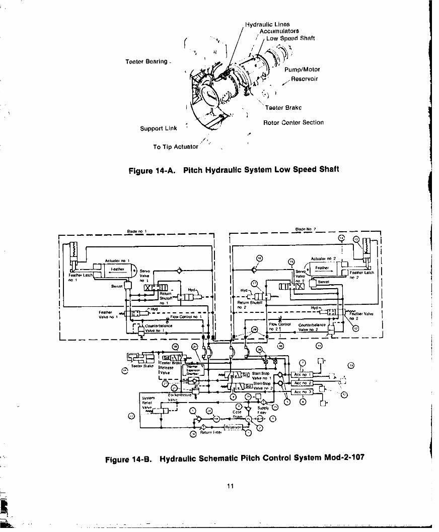
Hydraulic Lines
, Accumulators
- _. / , / Low Speed Shaft
Teeter Besring, _ _i_}} = ,,/Pump/M°t°rReserv°ir
"Teeter Brake
• Rotor Center SectionSupport Link '
,P
t1,
TO Tip Actuator
Figure 14-A. Pitch Hydraulic System Low Speed Shaft
Figure 14-B. Hydraulic Schematic Pitch Control System Mod-2-107
11
1981019068-TSA14

i _atlon
Rotor Hub Low Speed ShaftSection
TeeterBrake
, Teete, Teeter Stop
; Hatch
ElastomericBearing
FIg!!.r_=.!5... The..H_Ub .....................................
.,+
_'_'=" - WiNd SeNSOrs
_%_%, /. Goal Box O1[ COOlOr
_' "'_" _"", I Generlllot COOling Extltlust
\\" "\\ k" _=_ -- , VenlilatOr S"'i !, " ";'4. /
'.... , "*d,I \ _.._ fl_ "NCURack --\ ,':Cl" "1" /'" - ,, i, | I_. ,
..... \ ""_" " / C "_l*i/'_'_l= I - I. i Ir _ (FlleEKtirlgull_oHomoVable I'lOoi valtelb \ _" _:'!_ _. + _iI " _ _. --
_X _-_ ....... ,li_ r[ _ Sysieml
.o,o,,<o,,,. .. ._.:,_; .,... ...a°o,,o_oo, -" ._ _ ._' _l_'_.l_:" _' Bo"o,,
.,::-.<_-• ,:,;.t_D<'q\ _,,o,,,o,• ' _(_ai BoX
t 1 _ _ N_cpIle 1"o elalioxm Acce$_
: =%
, _+OWE*I
ltl,t,ni_n,_rici_ Pi_ilfo!nl {;-il¥,ly _hultt='l_
Figure 16. General Nacelle Arrangement Mod-2-107
12
____ ,, i
1981019068-TSB01
Rotor Breko ...." ,
Gearbox "_. " |
o,,,o>::-_,,i,_\,,.,,_ \'---,
._ "._" \_ _.,oxMoont. .-'"_,,:--._''v'_"'J \ OilOuUet
",( _'_ _' Q_II Shaft Removable Coupling
-.__} -,X I'ixedCoupling"TeeterBearing Interface
Flgure17. DrlveTrain
Figure 18. Yaw Drive Installation
13 J'am
. " _ " ,.:;,, ' , ,, , , i
1981019068-TSB02

7--
• speed shaftand a spring-actuatedbrake attached equipment and protects these systems from:. to the generator frame, The device serves as a weather and dust." parking brake to prevent rotor motion when the_, systemIs not In operation. Tower, Foundation, and Facility Layout
Yaw Drive System The193-foot-hightowersupportsthe nacelleandrotor through the yaw bearing, The tower Is
-- 'i The yaw system connectingthe nacelle to the composed of a 150-ft-long, 10.ft-dlametertower turnsthe rotor into the windand holds If in cylindrical tube which flares to a 21-ft-diameterpositionas commandedby the yaw controlsystem base.The toweris mountedon a baseof reinforced
(fig. 18).Winddirectionsensorssendsignalsto the concrete• Each Mod-2 machine requiresa square
yawcontrolsystem.Theyawsystemthenholdsthe site, 400 It on a side.Withinthisconstant,however,
T_ heading within a few degrees of the long-term the final layoutof the machinesin anywind--turblneaverage wind direction, Thirty-second average cluster can be designed to take maximumwind directions are monitored, and the control advantageof availablewind power. The Goodnoesystem changesheadingwheneverwind direction Hills facility will be gathering data o_ possible
changes exceed 20°. This feature prevents intermachineeffects.
BI. extreme blade stress-andminimizespower lossesdue to rotor headingerror.
. A hydraulic brake providesdampingduringyaw- Mod-0 Simulation of Mod 2motion. Six additional brakes prevent inadvertentyawing of the nacelie.The powerfor the yaw drive The concept of a dynamicallysoft tower, noted
system and brakes is furnished by a hydraulic earlier to be a Mod-2 design innovation,was testedsystem in the nacelle, on the NASA Mod-0 at Plum Brook. Itwas not easy
to make the Mod-0 rigid truss-style tower
The Nacelle_ _ dynamically soft. To do so, engineersat the NASA
i Lewis Research Center designed gigantic leaf
Thenacellehousesthemajor Mod-2subsystems springs(fig. 19). They then lifted the entire Mod-0such as the drive train, generator, yaw bearing, and resettledit on the leafsprings.TheMeal-0thendrive subsystem, and the associated hydraulic operated with its newly teetered rotor to providesubsystems for pitch and yaw control. It also researchers an estimateof the dynamiceffects ofcontainscooling,fire protection,and mai_enance the,proposedMod-2 design.
Symmetric
i i Aboui
_._ Cent rline100 kW WTG
_i SoftTower
×/X '
12
/ /'_ _ /-- New Leaf Springs --
/ • . Sides
/'/ V-_ Grs_l_l i - i t-//;-oJrZO i 'hear- t i_;:'• Existing Foundation ..... nta -
Concept
Figure 19. Soft Tower Simulation Fixture
1981019068-TSB03
/_
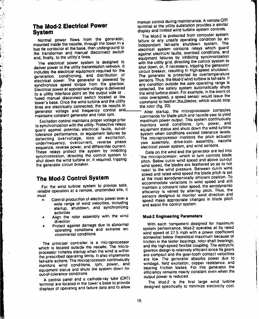
manual controlduringmaintenance,A remoteCRTThe Mod.2 Electrical Power terminal atthe utility substationprovidesa similar• _etem display and llmR_:1wind turbl_ system centres.
Normal power flows from the generator, The Mod-2 is protected from computer systeminsidethe the tower re,amounted nacelle, through
f_ failure or any unsafe operating condition by anbusfie contactorat the base, then undergroundto independent fall-safe shutdown system. TheL" the transformer and manual disconnect switch electrical system contains relays which guard_'_" and, finally, to the utlllty'slines, against electrical faults, overload conditions,and
equipment failures by Inhibiting synchronization=,: The electrical power system is designed to with the utilitygrid,directingthe controlsystemto_.: deliver powerto the utility transmissionnetwork. It shut down,Or, If necessary,tripping the generator
i includes the e_ocfrJca_equipment required for the circu_t breaker, resulting in high-speed shutdown.
generation, conditioning, and distribution of The generator is protected by overtemperatureelectrical power. The generator is powered by sensors.Thus,theMod,2windturbineisfall-safe.Ifsynchronousspeed torque from the gearbox, any conditionoutside the safe operating range isElectricalpowerat appropriatevoltageisdelivered detected, the safety system automaticallyshuts
_'- to a utility interface point on the output side of . the windturbinedown.For example, inthe eventoffused manual disconnect switch located at the rotor overspeed,a speed sensorwould issue thetower's base. Once the wind turbineandthe utility commandto feather_the_blades,whichwouldstopfines are electrlcally" connected, the _e resultsgenerator voltage and frequency control and-.___ he rotor(fig. 20),
After startup, the microprocessor computesmaintainsconstantgeneratorand rotor rpm, commandsfor blsde pitchand nacelleyaw to yield
Excitationcontrolmaintainspropervoltageprior maximumpoweroutput.This systemcontinuouslyto synchronizationwiththe utility,Protectiverelays monitors wind conditions, rpm, power, andguard against potential electrical faults, out-of- equipment statusand shutsdown the wind turbinetolerance performance, or equipment fai(ures by system when conditionsexceed tolerance levels.detecting overvoltage, loss of excitation, The microprocessormonitorsthe pitch actuatorunderfrequency, overcurrent, reverse phase yaw assembly, drive-train assembly, nacellesequence,reverse power, and differential current, electrical power system,and wind sensors.These relays protect the system by inhibitingsynchronization,directing the control system to Data on the wind and the generatorare fed intoshutdown the wind turbineor, if required, tripping "the microprocessor,which in turn controls bladethe generatorcircuitbreaker, pitch. Below cut-in windspeed and abovecut-out
windspeed, the blades are feathered so as to notreact tO the wind pressure. Between cut-in wind
The Mod.2 Control System speed and rated wind speedthe blade pitch is setat the most aerodynamically efficient position. To
For the wind turbine system to provide sate, accommodate variations in wind speed and stillreliableoperationat a remote, unattendedsite, it maintain a constantrotorspeed, the aerodynamicmust efliciency is varied by aJtering pitch. Thus, the
• * ContrOlproductionof electric powerovera sensors designed to monitor wind direction andwide range of wind velocities, including Speed make appropriate changes in blade pitchstartup, shutdown, and synchronizing and assist the contro) system.activities
• Align the rotor assembly with the wind Mod,2 Engineering Parametersdirection,= Protect against damage due to abnormal With each componentdesigned for maximum
operating conditions and extreme en- system performance, Mod-2 operates at its ratedvironmental conditions, wind speed of 27.5 mph with a power coefficient
somewhatbelow theoreticalmaximumbecause ofThe principal controller is a microprocessor frictionin the teeter bearings,rotor-shaftbearings,
which is located outside the nacelle. The micro- and the high-speedflexible coupling.The epicycUcprocessorinitiatesstartupwhen the wind is within gearboxdesignis relativelyefficientsince itsgearsthe prescribedoperating limits. It alsoimplements are compactand the gear-toothcontactvelocitiesfail-safeactions.The microprocessorcontinuously are low. The generator absorbs power due tomonitors wind conditions, rpm, power, and windage, field excitation, copper resistance, andequipmentstatus and shuts the system down for bearing friction losses. For this generator theout.of-toleranceconditions, efficiency remainsnearly constantevenwhen the
A control panel and a cathode-ray tube (CRT) outputpower is reduced.terminalare locatedinthe tower'sbase to provide The Meal-2 is the first large wind turbinedisplaysof operating and failure data and to allow designedspecificallyto minimizeelectricitycost.
15
1981019068-TSB04

3!,. +
_ Nacelle
• Pitch Yaw electrical Wind- acluator assembly power sensors
system
" • Drive • Status s Stalus • Brake • Generatorcommand9 • RPM commellda power
• Pump • Commandscommsnds
• Positioncommand• Pump commands Nacelle control unit
• Statusr, • • Windvelocity and direction
• ,TIppositions II Emergencyshutdown
L-system
status• Commands
• Autosync enableBus tie contactorcommand
Data• Status
Data.Ground Remote Ground.
Operational manual utility electricalinstructions control ' • Commends control power
units system
Figure 20. Control System Interface Diagram
In addition to engineering considerations, safety = Extremegustinessduringnormaloperationfeatures and procedures were inherent factors in in which the nacelle is at a yaw angledesigningfor cost. Environmentalandoperational within20° of the mean wind-hazards were significant.Environmentalhazards • Overspeed 115% of the normalrotor rpminclude seismicactivity, extreme winds, lightning, • Inadvertent blade feathering caused bytemperatures, hail, snow, ice moisture, and failure of the hydraulic or control systemwindborne objects. Operational hazards include = Inadvertent rotor, yaw, or teeter brakingthe stresses or "loads" that the wind turbine caused by failureof the hydraulicor con-components will be subjected to over their trol system.projected 30-year life.
Althoughstartup and shutdowncycles are few, The wind turbine was designed for specificrelativeto the total numberof rotations,the stress environmentalloads:exerted is relatively high and contributes =_--The turbine must withstand reasonablesignificantlyto wind turbinesystem fatigue. Each seismicdisturbancesturbine component experiences load variations + The blades, nacelle, and tower are de-duringevery startupand shutdown.Over 30 years, signed to withstandthe impact of largethe rotor may turn 200 to 400 milliontimes. The birds or other objects movingat 35 mphstartupsand shutdownscould number25,000. To • Turbine componentsand shippingcontain-
:_, assure safe-life, the machine is designed for ers mustbe desig_'_edto withstandtrans-75,000 startups to compensate for partial startups, portation and handling stressesOther cyclic stresses exist as well. For example, * The turbine must be able to sustaineach revolution of the rotor stressesthe blade with lightning strikes without damage
-- bending moments caused by gravity. Loads also • The turbine must withstand the impact ofvary because of decreases in wind speed near the t-in-diameter hailstonesground due to surface features or wind gusts. + The turbine must operate in temperatures
Operating loads or stress, environmental loads, between -40 ° to +120' F. +attd nonoperating loads were calculated indesigmng the Mod-2 The major parameters The wind turb;ne must also survive theseinvolvingoperatinq loads were nonoperatingstresses:
16
1981019068-TSB05

,, The turbine must withstand a maximum established lot such hardware, and fatigue tests: steadywind of 120 mph at 30 ft above have verified each estimate of safe hardware• groundwith the rotorparkedand braked lifetime. MOd-2 hardware Is designedto the sate-
in any position life conceptwhen highcost or weightpreventthe• The turbine must withstand 21 Ib/ff2 of tall-safe alternative.
snowonthe rotorbladewhenparked hori- Productassuranceor qualitycontrolassurancezontally and 41 Ib/ft2 of snow on the plansare an Integralpart of the Mod-2testingandnacelle roof safety programs. Components or processes must
• The turbine must withstand 2 in. of glaze meet qualityacceptance criteria. Inspectionsandice on all exposedsurfaces, testdata are documentedand reviewedfor proofof
, completion at the "readiness" reviews. TheseLoad calculations were the basis of Mod-2 reviews precede installation, first rotation, and
design and safety features (fig, 21). In addition to turning over the wind turbine system to thecalculating loads and sizing components operatingutllity.accordingly,designdetails forcritical components Where unique orcritical components,practices,were verified by structural tests of full-scale orproceduresare involved,morestringentcontrolshardware, are invoked• For example, critical ;orgings for
Three designconcepls apply to operation and blade material can be traced from the originalmelt -safety: tail-safe, safeqife, and product assurance, or rolling process for quality control purposes.Fail-safe means that a component or Structurewill
fail inone of three sate ways: adequatewarning is Failure Analystsgivensothat correctiveactioncan be taken;or thesystemautomaticallycorrects the problem;or the Extensiveanalyseswere conducted to estimatemacl'fineis automaticallyshutdown. the types of failure possible in all Mod-2
Mechanical and electrical components are components• For each possible failure thedesigned for safe shutdown upon failure. Where projected effect on the operation of the Mod-2wasthis is not possible, back-up systems keep the established. Corrective measures weremachine running until the operator is warned to incorporated to eliminate adverse or unsafetake action. Structural components are capable of effects. Typical examples of this type of failuresustaining detectable damage for a reasonable mode and effect analysis are shown in table 5.time between inspections without catastrophicfailure.
Allparts of the Mod.2structurenotfail-safewere Readiness Reviewdesigned to meet safe-life criteria. Safe-liferequiresthat the structuresustainno failure during The readiness review occurs after the windits Service life. Expected service lives are turbine system is completely installed, and all
PRE-CONCEPTUAL CONCEPTUAL PRELIMINARY DETAILED
DESIGN DESIGN DESIGN DESIGN DEPLOYMENT OPERATIONS
°l:e'at'°n ][m_mtenance mAnoal
'o"°'- ]l[.,ei.t ,on p_a,i U
[ T'a°,p°rta'=°n'lItr, ] LJ
• conl),_l • COn¢@pl_81 des,_nd,a_,r_ )m 'tnul_icl=#)')ttl •S._ _.._ e$1 * Eit 7 Sl_
r£qtjl,pmt_nl _ dc+'s'_'1 d,ll_lt_lS • MaDnlentlt.¢r. pl_rt$ • _ut.s_)_s., to (_Jtl_**erlC_
..L P=_(ablISh(N_ _ln[e_tal_(_ p aO
.,,o................,,..,. ,oo,.,,,,......,,,,........ ,,II
Figure 21. Mod.2 Project Flow Diagram
17
1981019068-TSB06
=.,
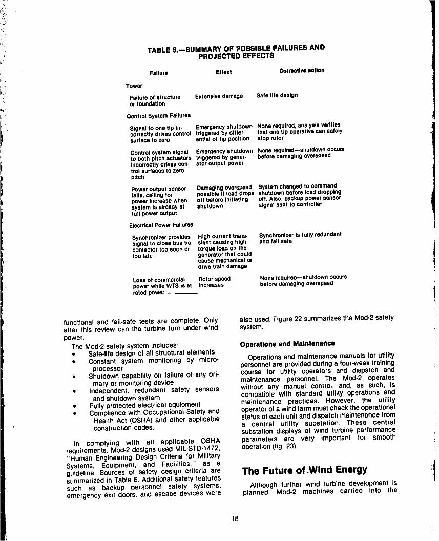
" TABLE5.--SUMMARY OF POSSIBLEFAiLUREBAND!_: PROJECTEDEFFECTS
i
!_ Failure Effect Correatlvllotionb .
'" Toweri..
Failureof structure Extensivedamage Safe life designor foundation
_"_ ControlSystemFailures
iL Signetto onetip in- Emergencyshutdown Nonerequired,analysisvedfiescorrectlydrivesoontrol triggeredby differ- that onetip operativecan safelysurfaceto zero entleiof tip position stop rotor
, Controlsystemsignal Emergencyshutdown Nonerequired--shutdowncecumto bothpitchactuators triggeredby gener- beforedamagingoverspeed
i i IncorreCtlydrlveacon. ator oufput powertroi surfacesto zeropitch
Poweroutputsensor Damagingoverspeed Systemchangedto commendfalls,callingfor possibleIf loaddrops shutdownbeforeloaddroppingpowerIncreasewhen off beforeInitiating off. Also,backuppowersensorsystemIs alreadyat shutdown signal sent to controllerfull poweroutput
ElectricalPowerFailures
Synchronizerprovides Highcurrenttrans- SynchronizerIs fullyredundantsignalto closebustie slantcausinghigh andfall safeconfactortoo soonor torqueloadonthetoolate generatorthat could
cause mechanicalordrivetraindamage
Lossof commerclal Rotorspeed Nonerequlred--ehutdownoccurspowerwhileWTS Is at increases beforedamagingoverspeedratedpower -
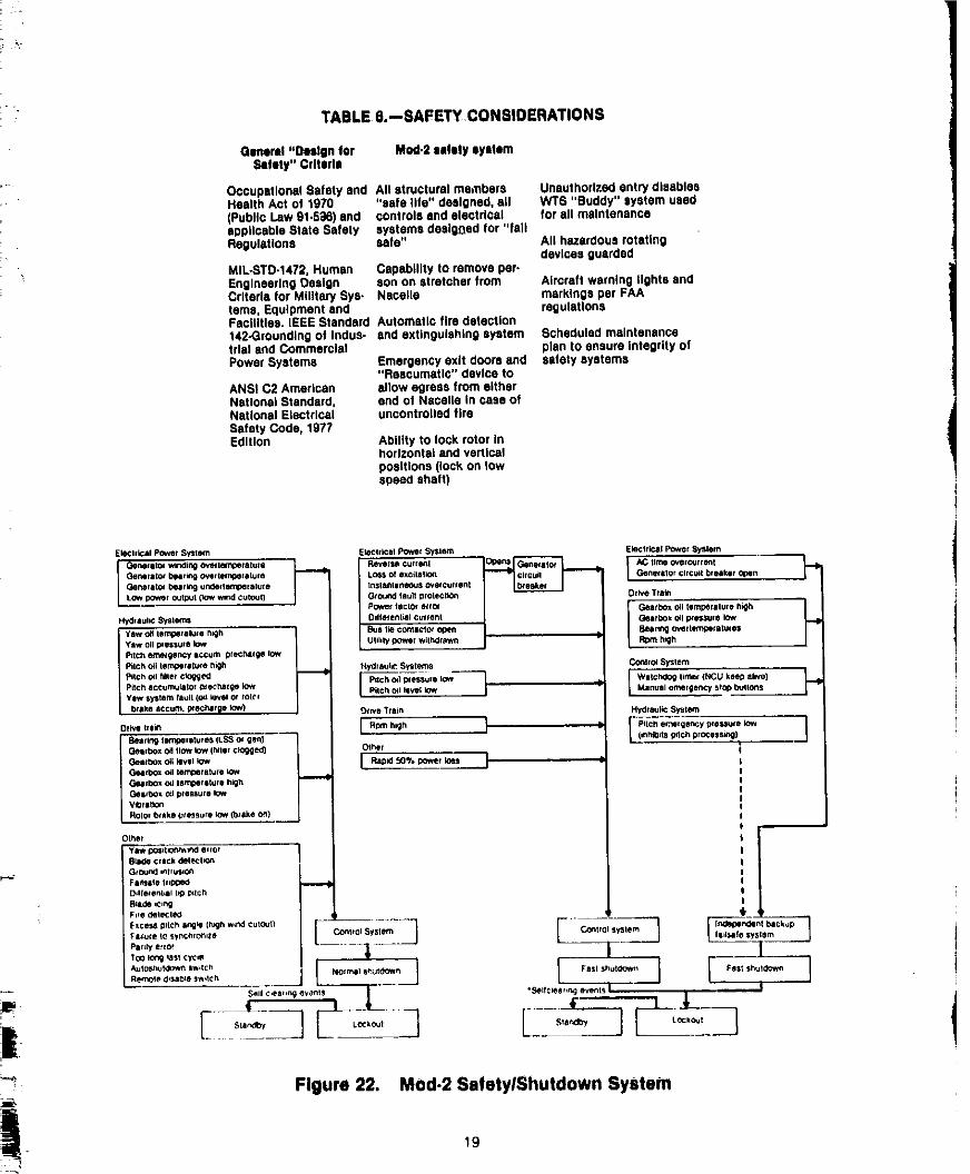
functionaland fail-safetestsare complete,Only alsoused.Figure22 summarizestheMod-2safetyafterthis reviewcan the turbineturnunderwind system.power.
TheMod.2safetysystemincludes: OperallonsandMaintenance= Safe-lifedesignof all structuralelements• Constant system monitoringby micro- Operationsandmaintenancemanualsforutility
processor personnelareprovidedduringa four-weektraining• Shutdown capability on failure of any prl- course for utility operators end dispatch and
mary Or monitoring device maintenance personnel. The Mod-2 operates• Independent, redundant safety sensors without any manual control, and, as such, is
and shutdown system compatible with standard utility operations and• Fully protected electrical equipment maintenance practices. However, the utility* Compliance with Occupational Safety and operator of a wind farm must check the Operational
Health Act (OSHA) and other applicable status of each unit and dispatch maintenance fromconstruction codes, a central utility substation. These central
substation displays of wind turbine performanceIn complying with all applicable OSHA parameters are very important for smooth
requirements, Mod-2 designs used MIL*STD-1472, operation (fig. 23)."Human Engineering Design Criteria for MilitarySystems, EquiDment, and FaciLities," as a
guideline. Sources of safety design criteria are The Future of.Wind Energysummarized in Table 6. Additional safety featuressuch as backup personnel safety systems, Although further wind turbine development iSemergency exit doors, and escape devices were planned, Mod.2 machines carried into the
18
1981019068-TSB07
_r"
TABLE &--SAFETY,CONSIDERATIONS
General "Design tor Mod,2 safely system_fety" Criteria
Occupational Safety end All structural members Unauthorized entry diesbfeeHealth Act of 1970 "safe life" designed, all WTS "Buddy" system used(Public Law 91.5_6) and controls and electrical for all maintenanceapplicable Stats Safety systems dee|_ed for "fallRegulations safe" All hazardous rotating
devices guardedMIL-STD-1472, Human Capability to remove per.Englneerlng Design son on stretcher from Aircraft warning ilghts andCriteria for MIlitap/eye- Nacelle markings per FAAterns, Equipment and regulationsFacilities. lEEk Standard Automatic fire detection142-Groundingof Indus- and extinguishing system Scheduled maintenancetrial end Commercial plan to ensure integrity ofPower Systems Emergency exit doors and safety systems
"Reecumatlc" device toANSi C2 American allow egress from eitherNational Standard, end of Nacelle in case ofNational Electrical uncontrolled fireSafety Code, 1977Edition Ability to lock rotor In
horizontal and verticalpositions (lock on lowspeed shaft)
EleCtriCal Power SYstem EleCtrical Power System Electrical POwer System
GeParlt0r I_llrin 9 over tempelalura LOIS of excdet_on GeP.erl Tot r_r¢_ b;oak_goner&tot _qllltlng ufldell_lp_lelule IrZSlahllln_B CNetCUIIOllt
LOWpov_r OUt]_l {low wind CUtOUt) Gr¢vJnd faull Wotectlon Drive _rram
Power taclOt eclol Get/box oil Ilmperllula high ]Hy_ i u.'¢ _lems Ddletenl_l c_¢_al Gearbox o41I_eSsule I_v
Yaw oil p_essut e low U lildy i_ve i vat_r#zw_ Rp_ P,_hPdch emelgency I¢cum pfecP,atgo low
Pilch cd lerrC_rilure h_lt Ftydlaul¢ Systems COnlt_ System
I ] I J-.Pitch accumutltol DlecP.llge low Pdch od pfelLSu,e low Watchdog timer (NCU keeD alive)Yahv lye tern II tz,'_{,_z _ or to_ Pilch oil level low Manual a,merSency sf0D I_,llOn_
t_ake _ccum. I_echer_l low) _.va Train Hydraulic System
o..,,., iR.h.h I I J8e_rlng temcel|tures (L_S ot gee} 1 (.nP4b_ts _t¢h process._
Gee fbox oa IlOW low (hill, clogged_ _ Ol_r
Gearbox (_Ito.ferule LOWGellbox Od tempelltuie h_hGe<)ox _1 pll_utll Iq_Vli_fltlO_
0[110¢1click _[(_:l'On
_llOtoal_ll lID t_tctt
F.ce.s P,tch .P_. (h_lh .,rid culo_tl ..... _ F '_ In_e_f blckupI:JIl_uIl_1_ sync;1fOt_lll_ COhtt OI Sy$11_m C._t iol _y_ I_r_l I . . _]
TO0 IOr_ ,agt ¢y¢. _ | l
Figure 22. Mod.2 Safety/Shutdown System
1981019068-TS B08
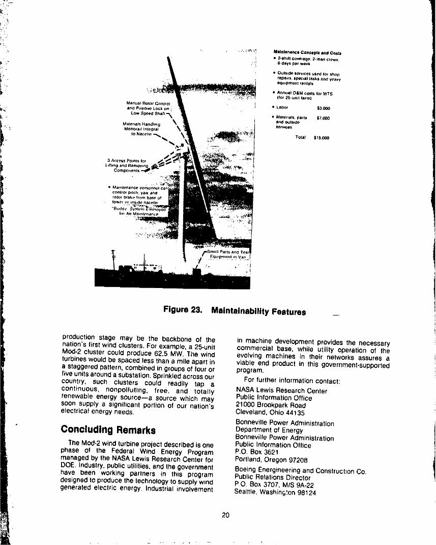
Figure 23. Maintainability Features
production stage may be the backbone of the in machine development provides the necessarynation's first wind clusters. For example, a 25-unit commercial base, while utility operation of theMod-2 cluster could produce 62.5 MW, The wind evolving machines in their networks assures aturbines would be spaced less than 8 mile apart in viable end product in this government-supporteda staggeredpattern, combinedin groupsof touror program.fiveunitsarounda substation,Sprinkledacrossour For further information contact:country, such clusters could readily tap acontinuous, nonpolluling, free, and totally NASA Lewis ResearchCenterPublic InformationOfficerenewable energy source--a source which maysoon supply a significant portion of our nation's 21000 BrookparkRoadelectrical energyneeds, Cleveland, Ohio 44135
BonnevillePowerAdministration
,.. Remarks Department OfEnergyBonneville PowerAdministration
The MOd-2windturbineprojectdescribed is one Public InformationOfficephase of the Federal Wind Energy Program P,O. Box 3621managedby the NASALewis ResearchCenter for Portland,Oregon 97208DOE. Industry,publicutilities,and the government BoeingEnergineeringand Construct=onCo.have been working partners in this program Public RelationsDirectordesignedtOproduce the technologyto supply wind P.O Box 3707, M/S 9A-22generated electric energy. Industrial involvement Seattle, Washin§°.on98124
20
....... 1981019068-TSBO£
r
" Bibliography Puthoff, R. L.: Fabdcatlon and Asseml_lyof the_- ERDA/NASA 100-Kilowatt Experimental Wind........__ Boeing Engineeringand ConstructionCo,: Mod-2 Turbine. NASATM X-3390, 1979,
Wind Turbine System Concept and PreliminaryDesignReport.Vol. I, Exec_tiveSummaryandVoI. Robblns,W. H.; Thomas,R, L.: Large, Horizontal-II, Detailed Report, DOEINASAIO002-8012,July Axis Wind Turblne Development.NASATM-79174,
• 1979. 1979.
Glasgow, J. C.; Robblns, W. H.: Utility Operational Robblns,W. H., Thomas, R. L, and Baldwin, D. H.:-' Experience on the NASNDOE Mod-OA 200 kW Large Wind Turblnes--A Utility Option for the
_' Wind Turbine. DOE/NSA/1004-7911, NASA, Generation of Electricity, DOEINASN023139-1,_; TM-79084. Paper presented at EnergyTechnology NASATM-81502, 1980.
. VI Conlerence; February26-28, 1979,Washington,D.C. Spera, D. A.: Comparisonof ComputerCodes for
- Calculating Dynamic Loads in Wind Turbines.Llnscott, B. S.; Glasgow, J.; Anderson, W.D.; DOEINASA/1028-78116, NASA TM-73773. PaperDonham, R. E.:ExperimentalData and Theoretical presented at Third Biennial Conference and
f Analysis of an Operating 100-kW Wind Turbine, Workshopon Wind Energy ConversionSystems,DOE/NASA/1028-78/15, NASA TM-73883. Paper September19-21, 1977, Washington,D.C.presented at Twelfth Intersociety EnergyConversionEngineeringConference,August 28, U.S, Department of Energy: EnvironmentalSeptember 2, 1977, Washington,D.C. Assessment, Eighteen Prospective Mod-2 Wind
Turbine Sites--The Goodnoe Hills, WashingtonLynette, R.; and Poore, R.: Mod-2 Failure Modes InstallationSite. DOEIEA-0096, 1979.anti Effects Analysis. DOE/NASA/0002-79/1, July1979,
21
" 1981019068-TSB10