the institution of structural engineers chartered ... · portable battery calculators may be used...
TRANSCRIPT

Structural Engineering Design and Practice
9.30 a.m. – 1 p.m. and 1.30 – 5 p.m. (Discussion between individuals is not permitted during theluncheon period).A period of fifteen minutes is provided for reading the question paper, immediately before thecommencement of the examination. Candidates are not permitted to write in answer books, or ondrawing paper or to use a calculator during this time.
Candidates must satisfy the Examiners in ONE question.
Important
The written answer to the question selected and any drawings must bear the candidate’s indexnumber and the question number in the bottom right-hand corner. Only the answer book(s)supplied by the Institution may be used. The candidate’s name should not appear anywhere in thescript.
Notes to Candidates
1. TO PASS THE EXAMINATION, CANDIDATES MUST SATISFY THE EXAMINERS INBOTH PARTS OF THE QUESTION ATTEMPTED.
2. A fair proportion of marks will be awarded for the demonstration of an understanding offundamental engineering concepts, as distinct from calculation of member forces and sizes.NOTE: In the calculation part of all questions, establishing “form and size” is taken to meancompliance with all relevant design criteria, i.e. bending, shear, deflection, etc.
3. In all questions 40 marks are allocated to Part 1 and 60 marks to Part 2.4. The Examiners are looking for sound structural designs.
It should also be remembered that aesthetics, economy and function are important in anycompetent engineering scheme.Candidates should read carefully the examiners’ reminder on Page 3.
5. Any assumptions made and the design data and criteria adopted must be stated.6. Portable battery calculators may be used but sufficient calculations must be submitted to
substantiate the design, and these should be set out as in practice.7. Good clear drawings and sketches are required; they should show all salient and structural
features to suitable scales and should incorporate adequate details.8. This paper is set in SI Units.
Now read ‘Reminder’ on Page 3 ☞
The Institution of Structural Engineers
Chartered Membership (Part 3) Examination
11 APRIL 2003
Chartered 2003 Part 3 3/6/03 4:47 PM Page 1 (Black plate)
(Old examination formatfor reference only)
3
A Reminder from Your Examiners
The work you are about to start has many features in common with other examinations which youhave tackled successfully but it is also has some which are unusual.
As in every examination you must follow carefully the NOTES FOR CANDIDATES set out foryour guidance on the front cover of this paper; allocate the available time sensibly and set out yourwork in a logical and clear way.
The unusual requirement of the examination is that you must demonstrate the validity of thetraining and experience that you have acquired in recent years. The Institution must be satisfiedthat you are able to bring all the various skills you are expected to possess to the effective solutionof structural design problems – whether or not the problem is presented in terms that are withinyour actual experience.
Chartered Structural Engineers must have an ability to design and a facility to communicate theirdesign intentions. Where you are required to list and discuss possible structural solutions you mustshow by brief, clear, logical and systematic presentation that you understand the general structuralengineering design principles involved.
In selecting and developing your design you should also remember the guidance given in theInstitution’s report, ‘Aims of Structural Design’, and in particular:
(1) ‘the structure must be safe’,(2) ‘a good design has certain typical features – simplicity, unity and necessity’,(3) ‘the structure must fulfil its intended function’.
If you have difficulty in deciding the correct interpretation of a question, pay particular attentionto point 5, Notes to Candidates, on the front cover. The examiners will take into account yourinterpretation – and the design you base on this – if this is clearly stated at the beginning of youranswer.
Chartered 2003 Part 3 3/6/03 4:47 PM Page 3 (Black plate)

4
Chartered 2003 Part 3 3/6/03 4:48 PM Page 4 (Black plate)

5
Question 1Tea production facilityClient’s requirements1. A tea production facility with a full height production area and first floor offices, staff room, kitchen
and canteen areas as shown in Figure Q1. The elevations are to be clad with an appropriate lightweighthorizontally spanning sheeting. 25% of the first floor storey is to be glazed.
2. The Client has stated that the external supports are to be exposed as a distinctive feature. The rooffinish can be of any material subject to the requirement of minimum future maintenance costs.
3. To highlight the exposed structure, the external wall elevations are to be set back 1.5m from the edgeof the roof. These walls are to be as thin as possible and non-structural.
4. No more than five internal columns will be permitted anywhere at ground floor level. 5. At ground floor level the external supports must be spaced at least 14.0m centre to centre on all
elevations.
Imposed loading6. Roof (production area) 1.60kN/m2 plus a 50kN lifting point load at any one location on
the primary structure.Roof (all other areas) 1.0kN/m22
First floor 3.5kN/m2
Ground floor (production area) 35.0kN/m2
Ground floor (all other areas) 10.0kN/m2
The loading includes an allowance for services, ceilings and floor finishes.
Site conditions7. The site is flat and situated on the outskirts of a small coastal town.
Basic wind speed is 44m/s based on a 3-second gust; the equivalent mean hourly wind speed is 22m/s.Note: The 3 second gust speed is used in the British Standard CP3 and the mean hourly wind speed isused in the British Standard 6399. Candidates using other codes and standards should choose anappropriate equivalent wind speed.
8. Ground conditions:Boreholes 1, 2, 5 & 6 Ground level – 3.0m Sand. N values vary linearly with depth
from 3 to 15.3.0m – 5.0m Sandy clay. C = 40kN/m2.Below 5.0m Sandstone. Allowable bearing pressure =
1000kN/m2.Boreholes 3 & 4 Ground level – 6.0m Sand. N values vary linearly with depth
from 3 to 15.6.0m – 9.0m Sandy clay. C = 40kN/m2.Below 9.0m Sandstone. Allowable bearing pressure =
1000kN/m2.
Groundwater was encountered at 1.0m below ground level. Sulphate (SO4) concentrations of up to0.3g/l were measured in the groundwater from each borehole.
Omit from consideration9. Detailed design of access staircases.
PART 1 (40 marks)a. Prepare a design appraisal with appropriate sketches indicating two distinct and viable solutions for
the proposed structure. Indicate clearly the functional framing, load transfer and stability aspects ofeach scheme. Identify the solution you recommend, giving reasons for your choice.
b. After construction of the superstructure has started, the Client requests that the roof loading and thelifting point load in the production area be increased by 1.0kN/m2 and 50kN, respectively. Write a letterto the Client explaining the effects that this would have on the structure.
PART 2 (60 marks)For the solution recommended in Part 1(a):
c. Prepare sufficient design calculations to establish the form and size of all principal structural elements.d. Prepare general arrangement plans, sections and elevations to show the dimensions, layout and
disposition of the structural elements for estimating purposes.e. Prepare clearly annotated sketches to illustrate details of:
(i) The connection between the exposed external structure and the foundation.(ii) The relationship of the roof, exposed and first floor structures.
f. Prepare a detailed method statement for the safe construction of the building and an outlineconstruction programme.
Chartered 2003 Part 3 3/6/03 4:48 PM Page 5 (Black plate)

6
17.5
m
Chartered 2003 Part 3 3/6/03 4:48 PM Page 6 (Black plate)

7
Question 2Call centre Client’s requirements1. A call centre building with provision for a future 2 storey extension; see Figure Q2. 2. The external walls are to be clad with masonry incorporating a 1.35m high continuous zone of glazing.
The roof is to have a slight slope to facilitate drainage. 3. The maximum storey height is to be 4.0m with a clear floor to ceiling height of 2.7m; see detail B on
Figure Q2.4. Only one line of internal columns will be permitted in each longitudinal direction and external column
spacing must be at least 7.0m, centre to centre.5. In addition, a two storey fully glazed reception area is required, as shown in Figure Q2. No internal
columns will be permitted within this area.
Imposed loading6. Roof 1.0kN/m2
All floors 5.0kN/m2
Loadings include an allowance for partitions, ceilings, services and finishes.
Site conditions7. The site is a sloping, previously undeveloped area of land on the outskirts of a large town.
Basic wind speed is 46m/s based on a 3 second gust; the equivalent mean hourly wind speed is 23m/s.Note: The 3 second gust speed is used in the British Standard CP3 and the mean hourly wind speed isused in the British Standard 6399. Candidates using other codes and standards should choose anappropriate equivalent wind speed.
8. Ground conditions:Borehole 1 Ground level – 1.0m Made ground comprising clayey silt with gravel and
brick fragments. N varies randomly from 1 to 45.
1.0m – 5.0m Silty sand and gravel. N varies linearly with depthfrom 3 to 15.
Below 5.0m Weathered rock. Allowable bearing pressure = 500kN/m2.
Borehole 2 Ground level – 0.25m Made ground comprising clayey silt with gravel andbrick fragments. N varies randomly from 1 to 45.
Below 0.25m Weathered rock. Allowable bearing pressure = 500kN/m2.
Groundwater was not encountered. The soil profile varies linearly between the two boreholes and isrepresentative of the whole site.
Omit from consideration9. Detailed design of the service core facilities (e.g. staircases).
PART 1 (40 marks)a. Prepare a design appraisal with appropriate sketches indicating two distinct and viable solutions for
the proposed structure including provision for the future 2 storey extension. Indicate clearly thefunctional framing, load transfer and stability aspects of each scheme. Identify the solution yourecommend, giving reasons for your choice.
b. Following completion of construction, there was some minor seismic activity in the region. Write aletter to your Client explaining the implications of such activity and how it might affect the building.
PART 2 (60 marks)For the solution recommended in Part 1(a):
c. Prepare sufficient design calculations to establish the form and size of all principal structural elements.d. Prepare general arrangement plans, sections and elevations to show the dimensions, layout and
disposition of the structural elements for estimating purposes.e. Prepare clearly annotated sketches to illustrate details of:
(i) The support structure for the side glazing in the reception area.(ii) A section through the East end of the building showing the provisions made for the future
extension.f. Prepare a detailed method statement for the safe construction of the building and an outline
construction programme.
Chartered 2003 Part 3 3/6/03 4:48 PM Page 7 (Black plate)
8
Roadway
Chartered 2003 Part 3 3/6/03 4:48 PM Page 8 (Black plate)

9
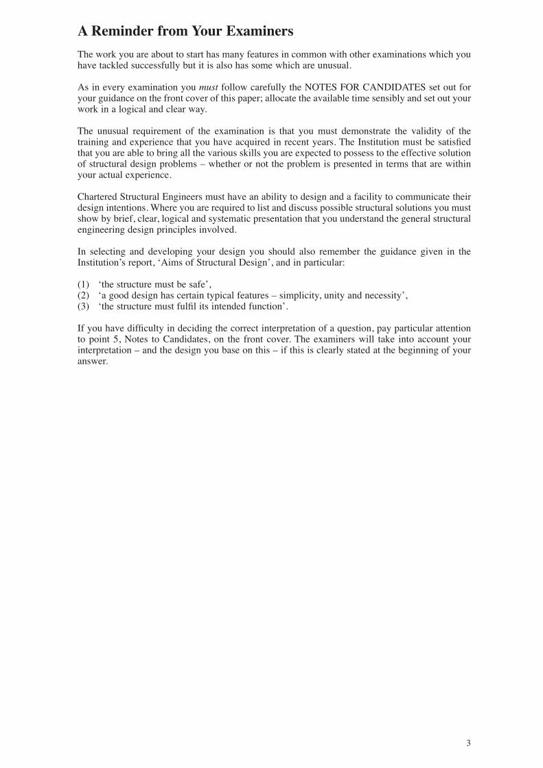
Question 3Railway bridge Client’s requirements1. A new bridge to support an existing three track railway that is currently supported on an embankment
as shown in Figure Q3. The embankment, which is overgrown with vegetation and trees, is of densefill construction and has side slopes of 1 (horizontal) to 1 (vertical). A level access road for a newhousing development is to be constructed beneath the railway; the new bridge is required to supportthe railway over the access road. The centreline of the access road is to be perpendicular to the railway.
2. The railway is to remain in service as much as possible during the construction of the new access roadand bridge. It is possible for the entire railway to be closed for long periods. Alternatively, one or moreof the tracks may be closed during the period 22.00 hrs to 06.00 hrs on the following day. As the Clientwill be required to pay for the costs of any disruption to the rail service, the most acceptable designsare those that will involve minimum closure.
3. The new access road has a 7.3m wide roadway with a 2.0m wide footpath on each side. The minimumclearance between the underside of the new bridge and the roadway is to be 5.0m.
4. Each pair of rails is supported on concrete sleepers and ballast; the distance between the top of eachrail and the top of the new bridge deck is to be 0.75m. The new bridge deck is to have a minimumwidth of 11.545m measured between the inside faces of the parapets, as shown in Figure Q3.
Imposed loading5. Vertical loading for each track
(half the load is to be applied to each rail) 100kN/m and a single point load of 300kN.Horizontal braking load applied to each track (half the load is to be applied to each rail) 800kN
Rails, sleepers and ballast 15.0kN/m2
All three railway tracks may carry railway loading at the same time.The vertical loads are distributed through the sleepers and the ballast at a slope of 2 (vertical) to 1(horizontal).
Site conditions6. The site is on the outskirts of a town within 50m of housing.7. Typical ground conditions:
Ground level – 0.2m Topsoil.0.2m – 8.0m Sandy clay. C = 100kN/m2.Below 8.0m Rock. Allowable bearing pressure = 1500kN/m2.
The water table is at 2.0m below ground level (see Figure Q3).
Omit from consideration8. Design of track, access road, detailed consideration of wind loading and detailed description of track
removal and construction.
PART 1 (40 marks)a. Prepare a design appraisal with appropriate sketches indicating two distinct and viable solutions for
the proposed structure. Indicate clearly the functional framing, load transfer and stability aspects ofeach scheme. Identify the solution you recommend, giving reasons for your choice.
b. After your recommended solution has been accepted, the Client asks that the headroom under thebridge be increased to 6.5m. Write a letter to the Client explaining the effects that this would have onthe design and the construction of the bridge.
PART 2 (60 marks)For the solution recommended in Part 1(a):c. Prepare sufficient design calculations to establish the form and size of all principal structural elements
including the foundations.d. Prepare general arrangement plans, sections and elevations to show the dimensions, layout and
disposition of the structural elements for estimating purposes.e. Prepare clearly annotated sketches to illustrate details of:
(i) An end support showing any features to enhance durability and ease of maintenance. (ii) A section through the edge of the bridge deck showing the parapet and its connection.
f. Prepare a detailed method statement for the safe construction of the bridge and an outline constructionprogramme. Identify any rail closure requirements and any temporary works necessary to maintain thestability of the existing embankment.
Chartered 2003 Part 3 3/6/03 4:48 PM Page 9 (Black plate)
10
Chartered 2003 Part 3 3/6/03 4:48 PM Page 10 (Black plate)

11
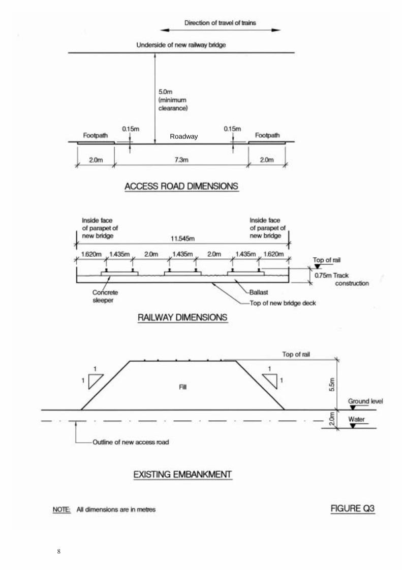
Question 4Youth hostelClient’s requirements1. An 8 storey youth hostel consisting of three identical residential blocks each linked to a central access
tower; see Figure Q4.2. Each residential block has 8 floors together with access corridors and an external emergency escape
staircase. A principal requirement is to provide a high standard of sound insulation to each bedroom.It is unlikely that this will be achieved by steel frame construction unless special provisions are made.
3. The central access tower comprises a circular service core housing lift/elevator shafts, stairs andservices. The service core is surrounded by an access area on each floor. All the services are housed ina roof top plant room over the service core.
4. The ground floor of each residential block is for recreational purposes and must have as fewinterruptions as possible. Clear ground floor space is required within an 8.0m wide strip along thelongitudinal centreline of each residential block.
5. Minimum clear headroom on all floors is to be 3.0m.6. A minimum two hours fire resistance is required for all structural elements.
Imposed loading7. Residential blocks Central access tower
Roof 2.2kN/m2 Access areas 3.5kN/m2
Bedroom floors 2.2kN/m2 Roof plant room 5.5kN/m2
The loading includes an allowance for services, ceilings and floor finishes.
Site conditions8. The site is level and is located adjacent to a newly developed area on the outskirts of a large town.
Basic wind speed is 46m/s based on a 3 second gust; the equivalent mean hourly wind speed is 23 m/s.Note: The 3 second gust speed is used in the British Standard CP3 and the mean hourly wind speed isused in the British Standard 6399. Candidates using other codes and standards should choose anappropriate equivalent wind speed.
9. Typical ground conditions:Ground level – 1.5m Made ground.1.5m – 6.0m Silty sand and gravel. N = 6.6.0m – 12.0m Dense to very dense sand and gravel. N varies linearly with
depth from 25 to 50.Below 12.0m Soft to firm silty clay. C varies from 26kN/m2 to 39kN/m2.The ground investigation terminated at 30.0m below ground level without encountering rock.Groundwater was encountered at 3.6m below ground level.
Omit from consideration10. Detailed design of lift/elevator shafts and staircases.
PART 1 (40 marks)a. Prepare a design appraisal with appropriate sketches indicating two distinct and viable solutions for
the proposed structure. Indicate clearly the functional framing, load transfer and stability aspects ofeach scheme. Identify the solution you recommend, giving reasons for your choice.
b. After receiving your completed design, the Client wants to convert the top floor and the roof of one ofthe residential blocks into an indoor swimming pool. Write a letter to your Client explaining the effectthat this would have on your proposed design.
PART 2 (60 marks)For the solution recommended in Part 1(a):c. Prepare sufficient design calculations to establish the form and size of all principal structural elements
(including the foundations) of the central access tower and a typical residential block.d. Prepare general arrangement plans, sections and elevations to show the dimensions, layout and
disposition of the structural elements for estimating purposes.e. Prepare clearly annotated sketches to illustrate details of:
(i) The connection between one of the floors of the central access tower and the service core.(ii) The connection between the foundations and the main support(s) to the central access tower.
f. Prepare a detailed method statement for the safe construction of the central access tower withparticular reference to any special measures necessary to achieve rapid construction.
Chartered 2003 Part 3 3/6/03 4:48 PM Page 11 (Black plate)

12
Chartered 2003 Part 3 3/6/03 4:48 PM Page 12 (Black plate)
13
Question 5Lighthouse Client’s requirements1. A lighthouse located in the sea, 500m from a shoreline, to mark the position of shallow water; see
Figure Q5.2. The lighthouse will normally be unmanned but temporary accommodation for maintenance personnel
is to be provided. Normal access for maintenance will be by helicopter and a 16.0m diameterhelicopter landing platform (a helipad) is to be provided at the top of the lighthouse.
3. A maximum of three columns is permitted between the lamp platform and the helipad. Columns mustminimise any obstruction of the light beam.
4. All structural elements are to be corrosion-resistant with a life to first maintenance of at least 20 years.5. Access is required for maintenance personnel from the helipad to the internal floors below and the base
of the lighthouse. The access provision may be internal or external.
Imposed loading6. Helipad 5.0kN/m2 applied over the whole area of the helipad acting with
a single point load of 60kN applied within a circle of 5.0m radius from the centreline of the lighthouse.
Lamp platform 20.0kN/m2
All internal floors 5.0kN/m2
Horizontal wave pressure 15.0kN/m2 (applied on the projected surface of the lighthousein any direction, up to a height of 12.0m measured from the surface of the seabed).
Site conditions7. The site is normally under tidal water but is exposed at mean low tide. The tidal range is 5.0m.
Basic wind speed is 50m/s based on a 3 second gust; the equivalent mean hourly wind speed is 25m/s.Note: The 3 second gust speed is used in the British Standard CP3 and the mean hourly wind speed isused in the British Standard 6399. Candidates using other codes and standards should choose anappropriate equivalent wind speed.
8. Typical ground conditions:Seabed level – 1.0m Sand. N = 8Below 1.0m Rock. Allowable bearing pressure = 500kN/m2
Omit from consideration9. Detailed design of the lamp and its support structure. Access provision other than that to the helipad.
PART 1 (40 marks)a. Prepare a design appraisal with appropriate sketches indicating two distinct and viable solutions for
the proposed structure including the foundations and helipad access provisions. Indicate clearly thefunctional framing, load transfer and stability aspects of each scheme. Identify the solution yourecommend, giving reasons for your choice.
b. After your recommended solution has been accepted, the Client requests that the structure be relocatedto a position 1000m from the shore in water that is 10m deep at low tide. The lamp is required toremain at the previous level. Write a letter to the Client explaining the effects that this would have onthe design and the construction of the lighthouse.
PART 2 (60 marks)For the solution recommended in Part 1(a):c. Prepare sufficient design calculations to establish the form and size of all principal structural elements
including the foundations and the helipad access provisions.d. Prepare general arrangement plans, sections and elevations to show the dimensions, layout and
disposition of the structural elements for estimating purposes.e. Prepare clearly annotated sketches to illustrate details of:
(i) The construction of the base of the lighthouse from seabed level to the lowest part of thefoundations.
(ii) The connection between the helipad and the main lighthouse structure.f. Prepare a detailed method statement for the safe construction of the structure.
Chartered 2003 Part 3 3/6/03 4:49 PM Page 13 (Black plate)

14
Chartered 2003 Part 3 3/6/03 4:49 PM Page 14 (Black plate)

15
Question 6Sports teaching building Client’s requirements1. A two storey sports teaching building containing laboratories and offices to be constructed on a filled site;
see Figure Q6.2. The building is to have a pitched roof with the upper storey contained within the roof space. All
external walls are to be clad in masonry.3. Emergency escape stairs are located at the rear of the building.4. A minimum one hour fire resistance is required for all structural elements.
Imposed loading5. Roof 0.75kN/m2
Floors 3.0kN/m2
Site conditions6. The building is located on an elevated site on the outskirts of a large town.
Basic wind speed is 46m/s based on a 3 second gust; the equivalent mean hourly wind speed is 23m/s.Note: The 3 second gust speed is used in the British Standard CP3 and the mean hourly wind speed isused in the British Standard 6399. Candidates using other codes and standards should choose anappropriate equivalent wind speed.
7. Ground conditions:Trial pits 1 to 4 Ground level – 0.15m Topsoil.
0.15 m – 1.5m Fill consisting of compacted demolition materials including occasional timber, steel reinforcing bars and bricks.
1.5m – 2.5m Dense gravel. N varies from 25 to 35.2.5m – 3.5m Weathered rock. Allowable bearing pressure =
200kN/m2.Below 3.5m Competent rock. Allowable bearing pressure =
1500kN/m2.Boreholes 5 &6 Ground level – 0.15m Topsoil.
0.15m – 5.0m Fill consisting of compacted demolition materials including occasional timber, steel reinforcing bars and bricks.
5.0m – 7.35m Dense gravel. N varies from 28 to 34.Below 7.35m Competent rock. Allowable bearing pressure =
1500kN/m2.Groundwater was encountered at 2.5m below ground level in both boreholes. Chemical testing of thesoil and groundwater showed the following:
pH = 9.2 and Sulphate (SO4) concentration in the groundwater = 3.2g/l.
Omit from consideration8. Design of internal staircase.
PART 1 (40 marks)a. Prepare a design appraisal with appropriate sketches indicating two distinct and viable solutions for
the proposed structure. Indicate clearly the functional framing, load transfer and stability aspects ofeach scheme. Identify the solution you recommend, giving reasons for your choice.
b. After the calculations and working drawings for your recommended solution have been completed, thearchitect asks for the building to be relocated by turning it through 90° so that the entrance porch facesEast. Write a letter to the architect to explain the effect that this would have on the design of thebuilding.
PART 2 (60 marks)For the solution recommended in Part 1(a):c. Prepare sufficient design calculations to establish the form and size of all principal structural elements
including the foundations and escape staircase.d. Prepare general arrangement plans, sections and elevations to show the dimensions, layout and
disposition of the structural elements for estimating purposes.e. Prepare clearly annotated sketches to illustrate:
(i) Details of the foundation at ‘X’.(ii) The detail at ‘Y’.(iii) The detail at ‘Z’.
f. Prepare a detailed method statement for the safe construction of the building and an outlineconstruction programme.
Chartered 2003 Part 3 3/6/03 4:49 PM Page 15 (Black plate)
16
Chartered 2003 Part 3 3/6/03 4:50 PM Page 16 (Black plate)

17
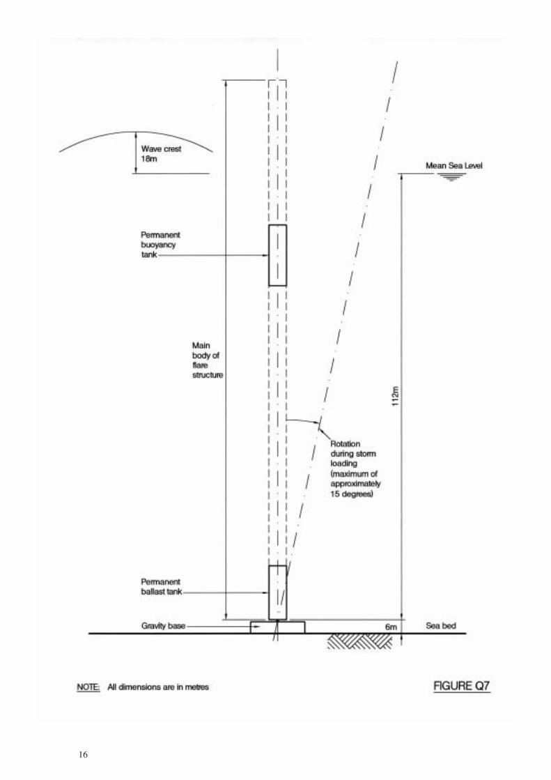
Question 7SPM flare structure Client’s requirements1. A SPM (single point moored) flare structure; see Figure Q7.2. The SPM flare structure is to be located adjacent to an offshore platform. The gas for flaring is
transported from the platform by a seabed pipeline and then by a flexible jumper to the bottom of theSPM structure. A rigid pipe runs the full height of the flare structure to deliver the gas to the flare tip.
3. The SPM flare structure comprises a gravity base that is connected via a universal joint to the mainbody.
4. The SPM flare structure resists lateral wave loads by rotation about the universal joint until therestoring moment from the permanent buoyancy tank provides equilibrium. The permanent buoyancytank also produces a tensile load on the main body. This tensile load is approximately cancelled by loadfrom a ballast tank just above the universal joint thus eliminating friction on the universal joint andalso minimising the size of the gravity base.
5. The flare structure will be installed by a surface tow to site followed by up-ending by flooding parts ofthe main body and/or by flooding temporary buoyancy tanks.
Imposed loading6. Ballast The dry density of iron ore (or similar) ballast may be taken to be 5300kg/m3.
The horizontal wave loading on the wetted part of the flare structure can be assumed to be a uniformlydistributed load w = 5.5nD kN/m, where n is the (actual or equivalent) number of vertical tubular members,each of diameter D metres.
Site conditions7. The SPM flare structure and the adjacent offshore platform are located in an area of open sea.
Basic wind speed is 40m/s based on a 3 second gust; the equivalent mean hourly wind speed is 20m/s.Note: The 3 second gust speed is used in the British Standard CP3 and the mean hourly wind speed isused in the British Standard 6399. Candidates using other codes and standards should choose anappropriate equivalent wind speed.
Omit from consideration8. Design of the gravity base structure below the universal joint, the temporary buoyancy tanks for
installation and the pipeline and flexible jumper.
PART 1 (40 marks)a. Prepare a design appraisal with appropriate sketches indicating two distinct and viable solutions for
the proposed SPM flare structure. Indicate clearly the functional framing, load transfer and stabilityaspects of each scheme for all conditions. Identify the solution you recommend, giving reasons foryour choice.
b. Having received your recommended design the Client wishes to consider an alternative installationmethod in which the SPM flare structure is transported to the site on a barge and lifted and rotated intoplace using two cranes mounted on a semi-submersible crane vessel. Write a letter to the clientdescribing the effects that this change will have on your chosen solution.
PART 2 (60 marks)For the solution recommended in Part 1(a):c. Prepare sufficient design calculations to establish the form and size of all principal structural elements
for all temporary and permanent conditions.d. Prepare general arrangement plans, sections and elevations to show the dimensions, layout and
disposition of the structural elements, including support points for the temporary conditions, forestimating purposes.
e. Prepare clearly annotated sketches to illustrate details of:(i) The connection of the permanent buoyancy tank to the adjacent structure.(ii) The tow head to be used during transportation and up-ending.(iii) The connection of the upper part of the universal joint to the main body of the flare structure.
f. Prepare a detailed description of the up-ending procedure following the surface tow of the structure tosite.
Chartered 2003 Part 3 3/6/03 4:50 PM Page 17 (Black plate)