the institution of structural engineers associate ... · portable battery calculators may be used...
TRANSCRIPT

Structural Engineering Design and Practice
9.30 a.m. - 1 p.m. and 1.30 - 5 p.m. (Discussion between individuals is not permitted during thelunch period).
A period of fifteen minutes is provided for reading the question paper, immediately before thecommencement of the examination. Candidates are not permitted to write in answer books, or ondrawing paper or to use a calculator during this time.
Candidates must satisfy the Examiners in ONE question.
Important
The written answer to the question selected and any drawings must bear the candidate's indexnumber and the question number in the spaces provided. Only the answer book(s) supplied by theInstitution may be used. The candidate's name should not appear anywhere in the script.
Notes to Candidates
1. TO PASS THE EXAMINATION, CANDIDATES MUST SATISFY THE EXAMINERS INBOTH PARTS OF THE QUESTION ATTEMPTED.
2. A fair proportion of marks will be awarded for the demonstration of an understanding offundamental engineering concepts, as distinct from calculation of member forces and sizes.NOTE: In the calculation part of all questions, establishing "form and size" is taken to meancompliance with all relevant design criteria, i.e. bending, shear, deflection, etc.
3. In all questions 35 marks are allocated to Section 1 and 65 marks to Section 2.4. The Examiners are looking for sound structural designs. It should also be remembered that
aesthetics, economy and function are important in any competent engineering scheme.Candidates should read carefully the examiners' reminder on Page 3.
5. Any assumptions made and the design data and criteria adopted must be stated.6. Portable battery calculators may be used but sufficient calculations must be submitted to
substantiate the design, and these should be set out as in practice.7. Good clear drawings and sketches are required; they should show all salient and structural
features to suitable scales and should incorporate adequate details.8. This paper is set in SI Units.
Now read ‘Reminder’ on Page 3 ☞
The Institution of Structural Engineers
Associate-MembershipExamination
16th APRIL 2004

3
Associate-Membership Examination, a reminder from yourExaminers,
The work you are about to start has many features in common with other examinations which youhave tackled successfully but it also has some which are unusual.
As in every examination you must follow carefully the NOTES FOR CANDIDATES set out foryour guidance on the front cover of this paper; allocate the available time sensibly and set out yourwork in a logical and clear way.
The unusual requirement of the examination is that you demonstrate the validity of the training andexperience that you have acquired in recent years. The Institution must be satisfied that you areable to bring all the various skills you are expected to possess to the effective solution of structuraldesign problems – whether or not the problem is presented in terms within your actual experience.
An Incorporated Structural Engineer must have the ability to design and a facility to communicatetheir design intentions. Where you are required to describe your structural solution you must showby brief, clear, logical and systematic presentation that you understand the general structuralengineering principles involved.
In selecting and developing your design you should also remember the guidance given in theInstitution’s report, Aims of Structural Design, and in particular:(1) ‘the structure must be safe’,(2) ‘a good design has certain typical features – simplicity, unity and necessity’,(3) ‘the structure must fulfil its intended function’.
If you have difficulty in deciding the correct interpretation of a question, pay particular attentionto point 5, Notes to Candidates, on the front cover. The examiners will take into account yourinterpretation – and the design you base on this – if this is clearly stated at the beginning of youranswer.


5
Question 1Country Park Visitors CentreClient’s requirements1. A new visitors centre for a country park consisting of two single storey octagonal buildings for
a shop and restaurant with a flat roofed foyer and canopy and a two storey octagonal office andexhibition centre; see Figure Q1.
2. The sloping roofs to the buildings are to be of timber rafters clad in natural slate tiles with aplasterboard soffit. The external walls are to be of glass curtain walling.
3. Only one column at ground floor level is permitted in the office and exhibition centre. A liftand stair core is to be located in the rear of this building.
4. The proposed structure is to be exposed internally and aesthetic consideration is to be given tothe design and connection details.
Imposed loading5. Roof 1.0 kN/m2
Floors 5.0 kN/m2 which includes an allowance for partitions
Site conditions6. The site slopes up from front to rear as indicated.
Basic wind speed is 40 m/s based on a 3 second gust; the equivalent mean hourly wind speedis 20 m/s.Note: The 3 second gust speed is used in the British Standard CP3 and the mean hourly windspeed is used in the British Standard 6399. Candidates using other codes and standards shouldchoose an appropriate wind speed.
7. Ground conditions:Ground level – 1.0m Top soil and fill1.0 m – 2.0 m Peat2.0 m – 4.0 m Sand N = 8 to 124.0 m – 8.0 m Dense sand N = 20Ground water was encountered at 4.0 m below ground level.
Omit from consideration8. Detail design of lift and stair core.
SECTION 1 (35 marks)a Prepare a design appraisal with appropriate sketches indicating a viable structural solution for
the proposed scheme. Indicate clearly the functional framing, load transfer and stabilityaspects of the scheme. Justify the reasons for your solution 25 marks)
b. After the design has been completed the client proposes to introduce a basement below theshop area for storage with a clear internal headroom of 2.5 m. Explain the effects this willhave on the original design. (10 marks)
SECTION 2 (65 marks)For the solution recommended in Section 1(a):c. Prepare sufficient design calculations to establish the form and size of all principal structural
elements including the foundations. (30 marks)d. Prepare general arrangement plans, sections and elevations to show the dimensions, layout and
disposition of the structural elements for estimating purposes. Prepare clearly annotatedsketches to illustrate details of:(i) A typical external column to floor detail at first floor level(ii) A typical detail at eaves level (25 marks)
e. Prepare a detailed method statement for the safe construction of the building. (10 marks)


7
Question 2Reception Area to Existing OfficesC l i e n t ’s re q u i re m e n t s1 . As part of an office refurbishment, it is proposed to add a new enclosed reception area to an
existing office building. The roof and walls are to be clad with a propriety glazing system thatrequires support at 1.0 m centres. A door 2.0 m wide by 2.0 m high is also to be provided; SeeFigure Q2.
2 . The reception area must have an 18.0m wide and 10m high volume of free space adjacent to theexisting building, unobstructed by structural elements.
3 . No internal columns are permitted. No columns are permitted between the reception area and theexisting bu i l d i n g .
4 . The existing building has exposed steel columns at roof level originally intended for thec o n s t ruction of additional storeys. The columns are I profile with a width of 0.25 m and a depthof 0.25 m. The additional storeys are no longer required but the columns may be used to supportadditional ve rtical and horizontal loads from the reception area structure. No other loads must beimposed on the existing bu i l d i n g .
5 . The existing building has a basement 4.0 m deep that extends 1.0 m from the envelope of theexisting building. The foundations of the reception area structure must not impose any additionalload on the basement.
Imposed loading6 . Roof imposed loading 1.0 kN/m2
Glazing system 1.0 kN/m2
Imposed loading includes an allowance for serv i c e s
Site conditions7 . The site is level and located in a town centre.
Basic wind speed is 40 m/s based on a 3 second gust; the equivalent mean hourly wind speed is20 m/s.Note: The 3 second gust speed is used in the British Standard CP3 and the mean hourly wind speedis used in the British Standard 6399. Candidates using other codes and standards should choosean appropriate wind speed.
8 . Ground conditions:Ground level - 0.5 m Concrete block paving over compacted granular fill N = 20B e l ow 0.5 m C l ay C = 100 kN/m2
No gr o u n d water was detected.
Omit from considera t i o n9 . E valuation of the effect of additional loads on existing columns.
1 0 . Ground floor slab of reception area.
SECTION 1 (35 mark s )a . Prepare a design appraisal with appropriate sketches indicating a viable structural solution for the
proposed scheme. Indicate clearly the functional framing, load transfer and stability aspects of thescheme. Justify the reasons for your solution. (25 marks)
b. After completion of the project the client proposes to plant a tree 5.0 m high and with a branchspread of 5.0 m diameter inside the reception area. Explain the effect this will have on the designand outline any resulting changes to your original proposal. (10 marks)
SECTION 2 (65 mark s )For the solution recommended in Section 1(a):c . Prepare sufficient design calculations to establish the form and size of all principal stru c t u r a l
elements including the foundations. (30 marks)d . Prepare general arrangement plans, sections and elevations to show the dimensions, layout and
disposition of the structural elements for estimating purposes. Prepare clearly annotated ske t c h e sto illustrate details of:( i ) Connection of new structure to existing columns( i i ) Connection of new columns to new foundations (25 marks)
e . Prepare a detailed method statement for the safe construction of the reception area. (10 marks)

9
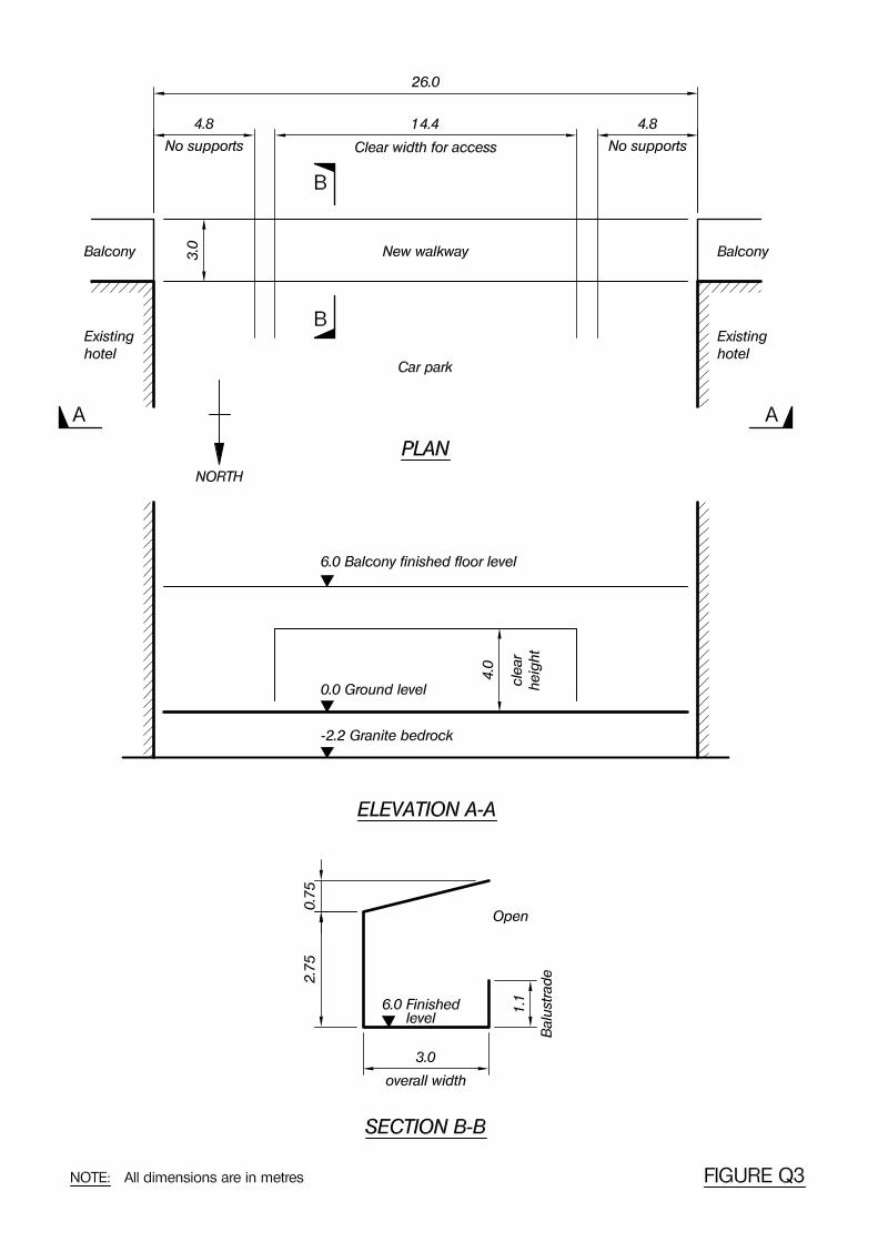
Question 3Hotel Walkway BridgeClient’s requirements1. To provide access between the balconies of two existing hotels a new walkway bridge is
required to be constructed across an existing car-park; see Figure Q3.
2. The walkway cannot be supported on the hotel buildings or balconies. No supports arepermitted within 4.8 m of the existing hotel buildings. A clear width of 14.4 m and a clearheight of 4.0 m are required for vehicular access to the car park.
3. The walkway is to be metal clad on the roof and north elevation but open on the south elevation(see Section B-B).
4. The car park will not be in use during construction of the walkway.
Imposed loading5. Walkway imposed loading 4.0 kN/m2
Roof imposed loading 1.0 kN/m2
Allowance for cladding 1.0 kN/m2
Site conditions6. The site is situated on the outskirts of a coastal town with the sea 3 km away.
Basic wind speed is 46 m/s based on a 3 second gust; the equivalent mean hourly wind speedis 22 m/s.Note: The 3 second gust speed is used in the British Standard CP3 and the mean hourly windspeed is used in the British Standard 6399. Candidates using other codes and standards shouldchoose an appropriate wind speed.
7. Ground conditions:Ground level to -0.5 m Made ground with a high concentration of poly - a r o m a t i c
hydrocarbons-0.5 m to -2.2 m Soft alluvium C = 20 kN/m2
Below -2.2 m Intact granite unconfined compressive strength = 200 MN/m2
Ground water was not encountered during the site investigation.
Omit from consideration8. Design of the cladding and its supports.
9. Detailed design of the balustrade.
10. Detailed design for vehicle collision loads.
SECTION 1 (35 marks)a. Prepare a design appraisal with appropriate sketches indicating a viable structural solution for
the proposed scheme. Indicate clearly the functional framing, load transfer and stabilityaspects of the scheme. Justify the reasons for your solution. (25 marks)
b. The client proposes a change to the brief. This requires the walkway to be curved in plan, witha 50m radius, between the supports. Explain the effect this will have on the design and outlineany resulting changes to your original proposal. (10 marks)
SECTION 2 (65 marks)For the solution recommended in Section 1(a):c. Prepare sufficient design calculations to establish the form and size of all principal structural
elements including the foundations. (30 marks)d. Prepare general arrangement plans, sections and elevations to show the dimensions, layout and
disposition of the structural elements for estimating purposes. Prepare clearly annotatedsketches to illustrate details of:(i) The bearing arrangements at the supports(ii) The support to foundation connection (25 marks)
e. Prepare a detailed method statement for the safe construction of the walkway bridge.(10 marks)

11
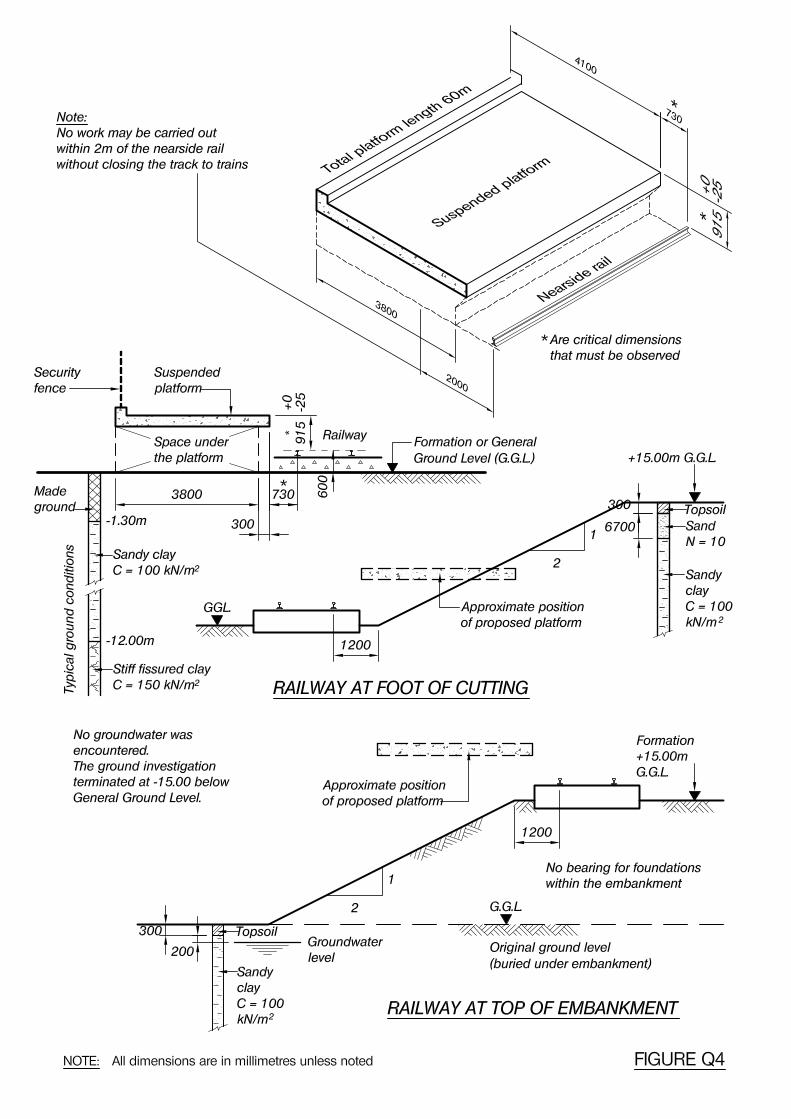
Question 4Railway Station PlatformClient’s requirements1. The components for a precast concrete railway platform, together with foundations that
support the platform on the typical ground conditions shown in Figure Q4. Insitu concrete maybe used in the foundations.
2. A rapid method of assembly with mobile craneage/lifting capacity limited to 6 tonne.
3. The space under the suspended platform slab shall be open, with minimum interruption ofservice runs.
4. Security fencing shall be installed along the back edge of the platform slab.
5. The platform shall be robust and durable with a non-slip surface. Service life is to be 60 years.
Imposed loading6. Uniformly distributed load of 10 kN/m2, or
Single wheel load of 100 kN with a square contact area at a pressure of 1.1 N/mm2
Site conditions7. The typical site is level and is located adjacent to a newly developed area on the outskirts of a
large town.Basic wind speed is 40 m/s based on a 3 second gust; the equivalent mean hourly wind speedis 20 m/s.Note: The 3 second gust speed is used in the British Standard CP3 and the mean hourly windspeed is used in the British Standard 6399. Candidates using other codes and standards shouldchoose an appropriate wind speed.
8. Ground conditions for the typical site are shown in Figure Q4.
Omit from consideration9. Access ramps, stairs and station buildings.
SECTION 1 (35 marks)a. Prepare a design appraisal with appropriate sketches indicating a viable structural solution for
the structure and foundations on the typical site. Indicate clearly the functional framing, loadtransfer and stability aspects of the scheme. Justify the reasons for your solution. (25 marks)
b Explain how the typical solution will be adapted for:- A site located at the foot of a cutting – see Figure Q4,- A site located at the top of an embankment – see Figure Q4 (10 marks)
SECTION 2 (65 marks)For the solution recommended in Section 1(a):c. Prepare sufficient design calculations to establish the form and size of all principal structural
elements in the suspended platform and its foundations. (30 marks)d. Prepare general arrangement plans, sections and elevations to show the dimensions, layout and
disposition of the structural elements for estimating purposes. Prepare clearly annotatedsketches to illustrate details of:(i) Connection between the precast units(ii) The fixing(s) at the foot of the security fence (25 marks)
e. Prepare a detailed method statement for the safe construction of the platform. No work maybe carried out within 2m of the nearside rail without closing the track to scheduledtraffic/trains. (10 marks)


13
Question 5Sculptor’s Studio and WorkshopClient’s requirements1. A successful sculptor requires a new three storey building as a studio and workshop; see Figure
Q5.
2. The building is to be octagonal in plan built around an open central quadrangle. The site is65 m by 65 m. The quadrangle contains four old trees whose roots must not be disturbed bynew foundations.
3. The sculptor is currently producing monumental concrete sculptures and has expressed astrong wish for the building to be of fair-faced concrete construction. He will accept a steelroof structure.
4. Column spacing generally is to be at least 7.5 m.
5. No interior columns are permitted at second floor level; note that columns may be placed onthe inner quadrangle perimeter.
Imposed loading6. Roof 1.5 kN/m2
All floors 12.0 kN/m2
The roof and floor loadings include an allowance for finishes, services, castings and partitions.
Site Conditions7. The site is level and located in a town centre.
Basic wind speed is 40 m/s based on a 3 second gust; the equivalent mean hourly wind speedis 20 m/s.Note: the 3-second gust speed is used in the British Standard CP3 and the mean hourly windspeed is used in the British Standard 6399. Candidates using other codes and standards shouldchoose an appropriate wind speed.
8. Ground conditions:Ground level to -3 m Topsoil N = 2 to 8-3 m to -12 m Clay C = 45 kN/m2
Below -12 m Mudstone with an allowable bearing pressure of 400 kN/m2
Omit from consideration9. Detailed design of lift shaft and stairs, although their contribution, if any, to the lateral stability
of the building must be explained in Section 1a.
SECTION 1 (35 marks)a. Prepare a design appraisal with appropriate sketches indicating a viable structural solution for
the proposed scheme. Indicate clearly the functional framing, load transfer and stabilityaspects of the scheme. Justify the reasons for your solution. (25 marks)
b. During the design process the client asks if it is feasible to roof over the central quadrangle toform an atrium, pruning the trees if necessary. Describe the implications that this will have onthe structure using sketches if necessary to illustrate your ideas. (10 marks)
SECTION 2 (65 marks)For the solution recommended in Section 1(a):c. Prepare sufficient design calculations to establish the form and size of all principal structural
elements including the foundations. (30 marks)d. Prepare general arrangement plans, sections and elevations to show the dimensions, layout and
disposition of the structural elements for estimating purposes. Prepare clearly annotatedsketches to illustrate details of:(i) A perimeter column to roof structure connection(ii) A main floor structural element (beam or slab) at first floor (25 marks)
e. Prepare a detailed method statement for the safe construction of the building. (10 marks)


15
Question 6Shop and Residential DevelopmentClient’s requirements1. A three storey building comprising 3 shop units at ground floor with 6 two storey apartments
above; see Figure Q6.
2. The interior of the 3 shop units should be clear of any columns and as free as possible of anyobstructions to facilitate the units being combined in the future.
3. The front elevation of the building at ground floor level should be as clear of obstructions aspossible.
4. To the rear of the apartment units an access walkway is required.
5. The roof structure will comprise timber trusses.
Imposed loading6. Roof 0.75 kN/m2
First and second floor 2.0 kN/m2
Ground floor 5.0 kN/m2
The first and second floor imposed loadings include an allowance for lightweight partitions.
Site conditions7. The site is level and is located within a large city.
Basic wind speed is 44 m/s based on a 3 second gust; the equivalent mean hourly wind speedis 22 m/s.Note: The 3 second gust speed is used in the British Standard CP3 and the mean hourly windspeed is used in the British Standard 6399. Candidates using other codes and standards shouldchoose an appropriate wind speed.
8. Ground conditions:Ground level – 3.0 m Loose fillBelow 3 m Chalk with allowable bearing pressure 150 kN/m2
No groundwater was detected.
Omit from consideration9. Detailed design of staircase and timber trusses.
SECTION 1 (35 marks)a. Prepare a design appraisal with the appropriate sketches indicating a viable structural solution
for the proposed scheme. Indicate clearly the functional framing, load transfer and stabilityaspects of the scheme. Justify the reasons for your solution. (25 marks)
b Upon completion of the design the client decides to utilize the upper floors for office use.Explain the effects of this change. (10 marks)
SECTION 2 (65 marks)For the solution recommended in Section 1(a):c. Prepare sufficient design calculations to establish the form and size of all principal structural
elements including the foundations. (30 marks)d. Prepare general arrangement plans, sections and elevations to show the dimensions, layout and
disposition of the structural elements for estimating purposes. Prepare clearly annotatedsketches to illustrate details of:(i) The ground floor structure and its junction with the foundations(ii) The junction of the supporting structure at first floor level (25 marks)
e. Prepare a detailed method statement for the safe construction of the building. (10 marks)