the importance of maintaining a generator’s … check change clean test w = weekly s =...
TRANSCRIPT
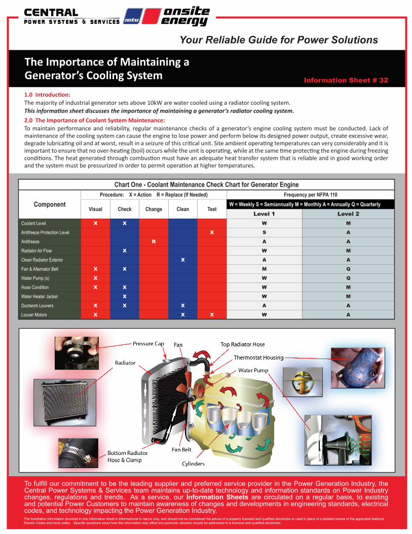
Chart One - Coolant Maintenance Check Chart for Generator Engine
ComponentProcedure: X = Action R = Replace (If Needed) Frequency per NFPA 110
Visual Check Change Clean TestW = Weekly S = Semiannually M = Monthly A = Annually Q = Quarterly
Level 1 Level 2
Coolant Level X X W M
Antifreeze Protection Level X S A
Antifreeze R A A
Radiator Air Flow X W M
Clean Radiator Exterior X A A
Fan & Alternator Belt X X M Q
Water Pump (s) X W Q
Hose Condition X X W M
Water Heater Jacket X W M
Ductwork Louvers X X X A A
Louver Motors X X X W A
1.0 Introduction:The majority of industrial generator sets above 10kW are water cooled using a radiator cooling system. This information sheet discusses the importance of maintaining a generator’s radiator cooling system.2.0 The Importance of Coolant System Maintenance:To maintain performance and reliability, regular maintenance checks of a generator’s engine cooling system must be conducted. Lack of maintenance of the cooling system can cause the engine to lose power and perform below its designed power output, create excessive wear, degrade lubricating oil and at worst, result in a seizure of this critical unit. Site ambient operating temperatures can very considerably and it is important to ensure that no over-heating (boil) occurs while the unit is operating, while at the same time protecting the engine during freezing conditions. The heat generated through combustion must have an adequate heat transfer system that is reliable and in good working order and the system must be pressurized in order to permit operation at higher temperatures.
The Importance of Maintaining a Generator’s Cooling System Information Sheet # 32
Your Reliable Guide for Power Solutions
The installation information provided in this information sheet is informational in nature only, and should not be considered the advice of a properly licensed and qualified electrician or used in place of a detailed review of the applicable National Electric Codes and local codes. Specific questions about how this information may affect any particular situation should be addressed to a licensed and qualified electrician.
To fulfill our commitment to be the leading supplier and preferred service provider in the Power Generation Industry, the Central Power Systems & Services team maintains up-to-date technology and information standards on Power Industry changes, regulations and trends. As a service, our Information Sheets are circulated on a regular basis, to existing and potential Power Customers to maintain awareness of changes and developments in engineering standards, electrical codes, and technology impacting the Power Generation Industry.
Colby, KS Branch1920 Thielen Ave.KS 67701785.462.8211 Ph785.462.8286 Fax
Liberty - Corporate Office9200 Liberty DriveLiberty, MO 64068816.781.8070 Ph816.781.2207 Fax
Woodward, OK Branch127 NW Hwy. 270OK 73801580.256.6014 Ph580.256.0314 Fax
Springfield, MO Branch3100 E. KearneyMO 65803417.865.0505 Ph417.865.4304 Fax
www.cpower.com
Wichita, KS Branch4501 W. IrvingKS 67209316.943.1231 Ph316.943.4560 Fax
Great Bend, KS Branch625 E. 10th St.KS 67530620.792.1361 Ph620.792.1364 Fax
Liberty, MO Branch1900 Plumbers WayLiberty, MO 64038816.415.6700 Ph816.415.6767 Fax
Liberal, KS Branch1150 E. Hwy. 54KS 67901620.624.7274 Ph620.624.7277 Fax
Salina, KS Branch1944B N. 9th St.KS 67401785.825.8291 Ph785.825.8282 Fax
CPSS-INFO#32 2015 PLC Enterprises, LLC
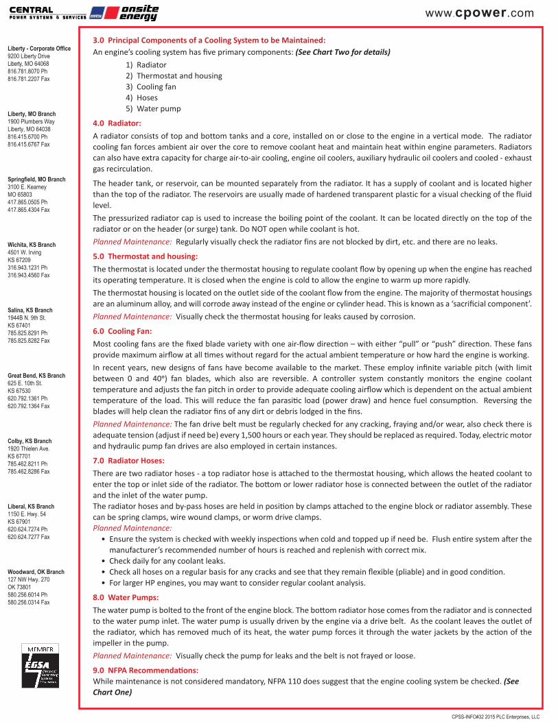
3.0 Principal Components of a Cooling System to be Maintained:An engine’s cooling system has five primary components: (See Chart Two for details) 1) Radiator 2) Thermostat and housing 3) Cooling fan 4) Hoses 5) Water pump
4.0 Radiator:
A radiator consists of top and bottom tanks and a core, installed on or close to the engine in a vertical mode. The radiator cooling fan forces ambient air over the core to remove coolant heat and maintain heat within engine parameters. Radiators can also have extra capacity for charge air-to-air cooling, engine oil coolers, auxiliary hydraulic oil coolers and cooled - exhaust gas recirculation.
The header tank, or reservoir, can be mounted separately from the radiator. It has a supply of coolant and is located higher than the top of the radiator. The reservoirs are usually made of hardened transparent plastic for a visual checking of the fluid level.
The pressurized radiator cap is used to increase the boiling point of the coolant. It can be located directly on the top of the radiator or on the header (or surge) tank. Do NOT open while coolant is hot.
Planned Maintenance: Regularly visually check the radiator fins are not blocked by dirt, etc. and there are no leaks.
5.0 Thermostat and housing:
The thermostat is located under the thermostat housing to regulate coolant flow by opening up when the engine has reached its operating temperature. It is closed when the engine is cold to allow the engine to warm up more rapidly.
The thermostat housing is located on the outlet side of the coolant flow from the engine. The majority of thermostat housings are an aluminum alloy, and will corrode away instead of the engine or cylinder head. This is known as a ‘sacrificial component’.
Planned Maintenance: Visually check the thermostat housing for leaks caused by corrosion.
6.0 Cooling Fan:
Most cooling fans are the fixed blade variety with one air-flow direction – with either “pull” or “push” direction. These fans provide maximum airflow at all times without regard for the actual ambient temperature or how hard the engine is working.
In recent years, new designs of fans have become available to the market. These employ infinite variable pitch (with limit between 0 and 40o) fan blades, which also are reversible. A controller system constantly monitors the engine coolant temperature and adjusts the fan pitch in order to provide adequate cooling airflow which is dependent on the actual ambient temperature of the load. This will reduce the fan parasitic load (power draw) and hence fuel consumption. Reversing the blades will help clean the radiator fins of any dirt or debris lodged in the fins.
Planned Maintenance: The fan drive belt must be regularly checked for any cracking, fraying and/or wear, also check there is adequate tension (adjust if need be) every 1,500 hours or each year. They should be replaced as required. Today, electric motor and hydraulic pump fan drives are also employed in certain instances.
7.0 Radiator Hoses:
There are two radiator hoses - a top radiator hose is attached to the thermostat housing, which allows the heated coolant to enter the top or inlet side of the radiator. The bottom or lower radiator hose is connected between the outlet of the radiator and the inlet of the water pump.The radiator hoses and by-pass hoses are held in position by clamps attached to the engine block or radiator assembly. These can be spring clamps, wire wound clamps, or worm drive clamps.Planned Maintenance:
• Ensure the system is checked with weekly inspections when cold and topped up if need be. Flush entire system after the manufacturer’s recommended number of hours is reached and replenish with correct mix.
• Check daily for any coolant leaks.• Check all hoses on a regular basis for any cracks and see that they remain flexible (pliable) and in good condition.• For larger HP engines, you may want to consider regular coolant analysis.
8.0 Water Pumps:
The water pump is bolted to the front of the engine block. The bottom radiator hose comes from the radiator and is connected to the water pump inlet. The water pump is usually driven by the engine via a drive belt. As the coolant leaves the outlet of the radiator, which has removed much of its heat, the water pump forces it through the water jackets by the action of the impeller in the pump.
Planned Maintenance: Visually check the pump for leaks and the belt is not frayed or loose.
9.0 NFPA Recommendations:While maintenance is not considered mandatory, NFPA 110 does suggest that the engine cooling system be checked. (See Chart One)