the heller alternative - hunwick...
TRANSCRIPT

Power station dry cooling The Heller alternative
As the demand for electricity rises inexorably, throughout Australia plans are being dusted off for new power stations. Most of these will be constructed at
inland sites, causing much of the planning effort to be directed towards securing adequate supplies of cooling water, and finding an acceptable way to
dispose of the salt-rich wastewater from the cooling towers—the blowdown. There is an alternative, dry cooling, and around the world many power station developers are adopting this technology, Australia included, if only to speed up
development approvals processes. The technology continues to advance and options are increasing, to the point where dry cooling may often be favoured
on economic grounds, particularly if realistic prices are assigned to the water consumed by evaporative cooling systems.
Most familiar is the direct air-cooled condenser. Less so is the Heller System, despite its having a number of features sufficient to warrant serious
consideration by the developers and designers of power plants of all sizes. This paper briefly reviews the issues involved in selecting power plant cooling systems and the alternatives available. Emphasis, however, is on the Heller
System. The writer had the opportunity to visit a number of significant installations of Heller systems in Turkey and Hungary in late June 2001, and
these are described.
Most of the energy we use to run our cars and other forms of transport, and to fuel our power stations, derives from the fossil fuels: coal, oil and gas, and uranium. This situation will persist for decades, even should fairly aggressive strategies be implemented for switching to renewables-based energy systems. Central to fossil fuel utilisation are heat engines: internal combustion, gas turbines and steam turbines; these last still the power industry’s workhorses. Steam generated at perhaps 200 times atmospheric pressure in a boiler enters the turbine and does useful work (turns the turbine rotor) as it expands through it until it ultimately exhausts at only one-tenth atmospheric pressure, ie. conditions of high vacuum.
The problem of waste heat
The trouble is, even after it has expanded through the turbine and cooled to little more than the temperature of a hot summer day, this steam is still steam, so it still contains more than half the total heat absorbed by the water fed to the boiler. The steam needs to be condensed back to water so it can be returned to the boiler to be converted into high-pressure steam once again, and the cycle (the Rankine Cycle) repeated. For condensation to continue, this heat

Dry cooling paper /2
must be carried away in some form of “sink”: a large flow of water (cooling water), or the atmosphere.
Much of the history of the development of power generation technology has involved a constant quest for greater efficiencies—to maximise the amount of useful work (read electricity) that can be extracted from a fuel, and minimise the amount that has to be rejected, somehow or other, to the environment.
At the beginning of the 20th century only a few per cent of the energy in fuels could be recovered as useful work. Now, a century later, the most modern combined-cycle power stations push this figure over the 50 per cent mark. In these, a gas or liquid fuel is first fired under pressure in a gas turbine (the topping cycle). Instead of steam expanding it is the gaseous combustion products that expand, doing work to drive an alternator. The fully expanded exhaust gases are still hot enough to generate high-pressure steam in a boiler, and this steam is expanded through a steam turbine essentially the same as those used when coal is the fuel to generate more power (the bottoming cycle). Even with such combined cycles, we are still left with the need to reject heat released when low-pressure steam exhausted from steam turbines is condensed back to water—around one-quarter of the heat energy in the fuel burned in the power station gas turbines.
What about cogeneration?
There are instances where uses can be found for such low-grade heat. A common use in countries having cold winters is to distribute hot water via a network of pipes to heat dwellings, offices and other facilities (factories, greenhouses etc.). Another use is for meeting the hot water needs of hotels, hospitals and other buildings. Then there are the substantial heat requirements of industrial processes such as evaporation, distillation and drying. A trend is to use such heat to produce chilled water for air-conditioning and some other industrial processes requiring cooling using absorption chillers. Engineers increasingly search for such cogeneration opportunities, but for the most part, the low-grade heat from power stations must be rejected to the environment. Even power stations supplying hot water to district heating schemes need to reject their waste heat in some other way in summer.
The medium used for accepting this heat is almost always a large flow of water, a reason why big power stations tend to be found on the coast or by a large lake or river. But coastal sites for power stations are now scarce, and inland Australia lacks rivers or lakes able to accommodate the waste heat from a large power station.
In New South Wales the approach adopted with the first big power station to be built away from the coast was to create an artificial lake by damming a tributary of the Hunter River. Lake Liddell was formed, and has served as the sink for the low-grade heat rejected by the Liddell Power Station. In turn, lake waters are warmed, evaporation rates from the warmed waters increase, so the heat energy rejected by the power station ultimately ends up in water vapour carried off into the air from the surface of the lake.
Evaporative cooling towers
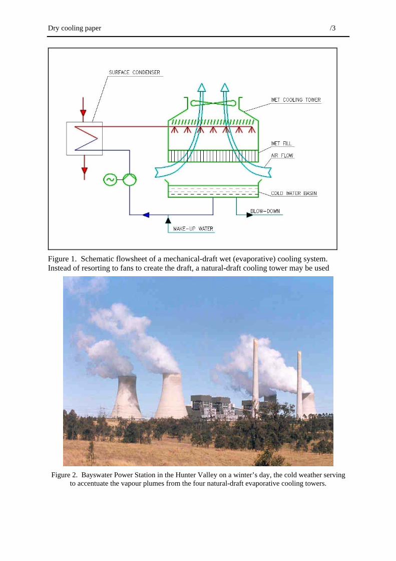
When the time came to build New South Wales’ next big inland power station, Bayswater, at a site across the New England Highway from Liddell, the designers adopted evaporative cooling towers. Here, the water is made to cascade through a draft of air. The the water is cooled, while the air, warmed and humidified, disperses the heat into the atmosphere (Figure 1).
Dry cooling paper /3
Figure 1. Schematic flowsheet of a mechanical-draft wet (evaporative) cooling system. Instead of resorting to fans to create the draft, a natural-draft cooling tower may be used
Figure 2. Bayswater Power Station in the Hunter Valley on a winter’s day, the cold weather serving
to accentuate the vapour plumes from the four natural-draft evaporative cooling towers.

Dry cooling paper /4
Fans usually create the necessary draft of air; these consume power and require maintenance, and can be noisy. Alternatively, it is possible to resort to the chimney effect to generate the necessary draft since the warmed and humidified air from a cooling tower is less dense than ambient air. This was done at Bayswater—its four “hyperbolic” concrete cooling towers are a distinctive feature (Figure 2).
Such cooling towers are characteristic of many of the world’s larger coal-fired and nuclear power stations. But being so distinctive, whenever a picture is shown of a nuclear power station the feature that often stands out is the cooling tower. Recall Three-Mile Island in Pennsylvania--at the time of the incident (now a quarter of a century ago), developments were reported on television night after night with a picture of this hapless nuclear power station as a backdrop, dominated as always by its cooling towers. A consequence has been the creation in the minds of many of the belief that such towers conceal nuclear reactors. They are of course nothing more than fat chimneys, empty apart from the plumbing and packing used to distribute the warm water from the power station condensers through the draft of ambient air rising through them.
Plumes and blowdown
Natural-draft evaporative cooling towers are made even more prominent by their cloud-like plumes, particularly on cold, still mornings and during wet weather. These plumes are pointers to the vast quantities of water lost to the atmosphere by evaporation. Not only must this water be made up, more is needed besides, because anything dissolved in the water added to make up for these losses remains in the circulating cooling water. There are practical limits to the extent these substances (usually, salts) can be allowed to become concentrated—if these limits are exceeded these salts can start to be deposited on any available surfaces the water contacts, fouling these and reducing the performance of the system. Make-up water can be treated to minimise tendencies for fouling, but there are limits. Some water has to be withdrawn from the circuit (and along with it, its content of dissolved salts) and replaced with additional fresh water to ensure salt concentrations in the cooling water circuit remain below prescribed limits.
Current environmental standards have the effect of severely limiting the options a power station has for disposing of this salty blowdown. In fact, the Bayswater Power Station raised the bar by installing systems for recovering pure water from blowdown to ensure no off-site discharges of such water. These systems remain world’s best practice, even though the power station is nearly two decades old.
And water scarcity
Globally, fresh water is increasingly being seen as a scarce resource, to be valued appropriately. For a new power station the costs of the water it needs for evaporative cooling can be substantial, and these costs will only increase. Furthermore, the access rights, and the construction works required to access the water, secure easements, transport it to the power station, and store it on site are expensive and often disruptive, so slow to be approved by regulatory authorities. Add difficulties with disposing of blowdown and the challenges imposed by keeping the water chemistry right while it is in the cooling system, it is little wonder power station designers increasingly seek alternatives to evaporative cooling.
The search for alternatives
There are several such alternatives. To introduce them we’ll start by observing that while most of the waste heat from a car engine leaves via the exhaust pipe, a substantial amount passes to the engine jacket cooling water. This is cooled for reuse by pumping it through the

Dry cooling paper /5
vehicle’s radiator1. Leaks aside, no water is lost from the vehicle’s cooling system—it is closed.
A steam turbine condenser in a large power station and a car engine jacket are similar in that both cause flows of circulating water to be heated, and this heat has to be removed before the water can be re-used in the condenser/engine cooling jacket. Of course, the amount of heat to be rejected from a large steam turbine condenser could be one million times greater than a typical car radiator has to reject when driving around the suburbs.
Still, size differences notwithstanding, this begs the question: instead of pumping it to an evaporative cooling tower, could the warmed water from the turbine’s condenser be pumped through what amounts to a giant car radiator? Indeed it can. In fact, one of the world’s largest coal-fired power stations rejects its waste heat in just this way—Kendall, in South Africa, another country where fresh water is scarce.
From afar Kendall resembles Bayswater, except there are six generating units instead of four (they are roughly the same size as Bayswater’s), and the hyperbolic cooling towers are much larger than Bayswater’s; they are the largest such concrete towers in the world. Indeed, they and the rest of the cooling system were so expensive that this power station, while working well and without using water on a day-to-day basis, is one of a kind.
In spite of the banks of fins, cooling water as a car radiator does is a much slower hence more expensive process than cooling water by evaporation. With the latter, the water and air are brought into intimate contact, facilitating a direct flow of heat energy from one to the other, while in a car radiator the heat energy must pass from the water to the air through the water-tube walls and fins.
Also, when water is cooled by evaporation, the heat transferred to the air is via both its rise in temperature (sensible heat), and in humidity (latent heat, ie. the amount of heat energy contained in water because of its state rather than temperature). In fact, the water evaporated in the cooling tower contributes most of the energy transferred from the circulating cooling water to the atmosphere. With a radiator-type cooling system, only sensible heat is transferred. In practical terms this means that to transfer the same amount of heat energy from water to air, with radiator-based cooling the volume of air required to flow through the cooling towers must be several times as great as with evaporative cooling. This is why those Kendall cooling towers are so large (Figure 3).
Then, if heat is to pass from water flowing through the radiator tubes to ambient air flowing outside them, the water must be hotter again. On those hot summer days when air temperatures can be at 40°C or more, this has severe implications for the performance of the steam turbine. High cooling water temperatures feed back to the temperatures in the steam turbine’s condenser--if steam is to be condensed on these tubes the steam itself must be hotter again. This reduces overall power station efficiency, ie. less electricity is sent out for the same consumption of fuel. The adverse economic consequences of this can easily exceed the higher capital cost of a Kendall-type dry cooling system.
In contrast, with evaporative cooling, it is not the ambient temperature (the dry-bulb temperature) that determines cooling efficiency, but the wet-bulb, the temperature that a thermometer records when its bulb is cooled by evaporation--when it is continuously wetted
1 Purists are asked to accept resort here to the term “radiator”. The author acknowledges that car radiators
and the “radiators” discussed below cool water flowing through their tube banks by convection, not by radiation. However, the convention is well established, so will continue to be used in this paper.

Dry cooling paper /6
as air flows across it. Low humidity is usual on the hottest summer days so evaporative cooling is very efficient, as anyone emerging from a swimming pool on such a day knows.
A reason Kendall’s cooling system was so expensive is that the heat released when steam is condensed must pass through two sets of heat exchanger surfaces: the walls of the tubes of the normal steam turbine condenser, and the walls of the tubes and fins making up the banks of the radiator panels in the huge cooling towers. Routes to efficiency gains and cost reductions derive from eliminating one of these two sets of heat-transfer surfaces.
Alternative 1: Air-cooled condensers
One way is to condense the steam turbine exhaust not on the surfaces of tubes through which water is passing, but directly onto the inside of tubes over which air flows. In this way, the heat released as the steam condenses is transferred directly to the atmosphere; the heat energy has to flow through the walls of only one set of tubes.
Such an air-cooled condenser looks very different to a normal condenser (usually a large box mounted directly under the turbine, obscured by support structures and piping) for the basic reason that heat is transferred from a metal surface to air far less efficiently than it is to flowing water, so much more such surface area must be exposed to air.
How is this achieved in practice? Rather like a tree does through its branches and leaves--turbine exhaust steam divides into several major branches (risers), which distribute it in turn via horizontal headers to a host of smaller tubes covered with fins to increase the total surface area exposed to the air. The finned tubes incline downward from the header, forming a pair of condenser banks that incline like the sides of the capital letter A. Powerful fans establish the necessary flow of air through the banks (Figure 4).
The entire branch network operates under vacuum, meaning that volumes of steam to be handled are very large. Yet there must be enough pressure in the turbine exhaust to force steam into the cooling tube extremities, even on hot summer days. This pressure feeds back to the turbine exhaust, limiting the total amount of expansion possible through the turbine, hence its thermal efficiency relative to an evaporative cooling system, even in cold weather.
The world’s largest air-cooled condenser system is installed at a sister power station to Kendall: Matimba, also in South Africa. While a little less expensive, this dry cooling system has performed less satisfactorily than has Kendall’s. A particular problem has been that when the wind blows from a direction such that the condenser banks are in the lee of the power station, hot air blown upwards by the fans from the condenser banks can recirculate to the fan inlets. The hotter air causes condenser efficiencies to fall, hence steam pressures to rise rapidly in the tubes, and backing up to the turbine blades, reducing the volumetric flow to an extent that may lead to flow-induced vibration of the last stage blading. Normal control systems cause the turbogenerators to trip before turbine blades can become damaged, but the cost and inconvenience of such trips is never trivial. Smaller air-cooled condenser installations are less likely to suffer from these hot-air recirculation problems.
It is a tribute to the designers and builders of air-cooled condenser systems that they generally work effectively, and are now accepted as being reliable. Leakages were a problem with earlier units installed—even a pinhole leak can see air rapidly contaminating the steam, reducing condensation efficiencies, while small leaks can be hard to locate. Installations, marketed mostly by major European companies including Balcke-Durr, GEA and Hamon, are proliferating worldwide, being favoured by independent power producers developing natural gas-fired combined-cycle power stations. Such power stations are normally fairly unobtrusive neighbours, so planning approvals can be secured quickly and with little difficulty--so long as major water supply and blowdown disposal facilities are not required.

Dry cooling paper /7
Figure 3, Kendall Power Station, South Africa, during construction in the late 1980s. Note the much
larger cooling towers cf. Bayswater (three of a total of six shown)—they are 170 metres tall; Bayswater’s are 132 metres; heat loads per tower at both power stations are similar.
Figure 4. Direct air-cooled condenser-based dry-cooling system. Larger systems would have many
sections
Dry cooling paper /8
Alternative 2: The Heller System
Recalling again Kendall-type dry cooling systems, the other way to eliminate one of the two heat exchanger stages is by replacing the conventional condenser with its many thousands of tubes with one that operates without tubes, that has no heat-transfer surface.
Steam turbine exhaust will condense directly onto a spray or cascade of cool water. A condenser based on this principle - it would be a chamber filled with little more than rows of sprays and their water-supply piping - could in principle, replace the large, heavy turbine condenser and the temperature differential across the walls of its tubes. The warmed mix of cooled water from the sprays and steam condensed by it, collects in the bottom of the chamber.
It remains to cool this warmed water - to reject to the atmosphere via radiator banks the heat it collected from the condensing steam - so it may be re-used. The required flow of air through the radiator banks may be secured by fans (Figure 5), or resort to the chimney effect via natural-draft cooling towers (Figure 6).
An amount of water equal to that of steam condensed is withdrawn and pumped to the power station boilers to be converted back to high-pressure steam for the turbine. The loop is closed when this steam returns to the condenser as steam turbine exhaust. Since the water fed to the boilers mixes with that circulated through the cooling radiators, the water must be of boiler feedwater quality. But since the cooling system is fully closed, no more water is required than to make up for normal boiler losses, which remain the same irrespective of the cooling system.
This indirect dry-cooling system as outlined (to distinguish it from the direct air-cooled condenser-based dry-cooling system of Figure 4) takes its name from its inventor, Professor Heller, a Hungarian. And it is a Hungarian company, EGI2, that has continued to develop and market this system over the last half century, to the extent that around the world there is now around 15,000 MW of power station generation capacity in operation or under construction using the Heller dry cooling system.
This figure approaches the total power generation capacity utilising direct air-cooled condensers. But since most Heller systems are in Middle-East countries, in some cases where visitor access may be limited, they tend to be less familiar to those of us living elsewhere.
Why consider Heller systems?
The Heller System has several appealing features that warrant its more serious consideration by developers and designers of power plants of all sizes.
Positive-pressure operation
Apart from the direct-contact jet condenser itself, the entire cooling system operates at positive pressures. Should any leaks arise there will be a show of water that greatly simplifies the task of locating them, while so long as the leak is relatively minor, the operation of the cooling system will be unaffected.
2 EGI Engineering-Contracting is now a wholly owned subsidiary of GEA, a large company perhaps best
known outside Germany for its air-cooled condensers.

Dry cooling paper /9
Figure 5. Heller indirect dry cooling system, mechanical-draft. This variant is suited to deluging, ie. enhancing cooling by flooding the radiator banks with water. Compact Heller dry-deluged cooling
systems are finding favour from turbo-machinery companies as auxiliary coolers.
Steam Turbine
DC Condenser
Boiler Feed Water
CoolingTower
Recovery Turbine
CW Pump
Water to AirHeat Exchanger
Dry
Figure 6. Heller dry cooling system, natural-draft variant. The natural-draft cooling tower may be of reinforced concrete (usually having the distinctive “hyperbolic” shape, or of aluminium-clad structural
steel. The cooling deltas are normally installed vertically, as shown.
Then, since there is no need to force steam to the extremities of an extensive branch network of evacuated tubes, when weather conditions permit (when it is cool), steam turbine exhaust pressures can be lower, leading to higher power station thermal efficiencies—more power for the same fuel use.

Dry cooling paper /10
Mechanical-draft and natural-draft
A direct-contact jet condenser and its associated radiator banks are linked only by water pipes, allowing greater locational flexibility—an air-cooled condenser must be installed adjacent to the steam turbine to minimise the distance exhaust steam, under vacuum conditions, has to flow.
Perhaps more significantly, the Heller System allows designers to choose between mechanical-draft and natural-draft designs for securing the necessary air-flow. The radiator banks of a mechanical-draft Heller dry cooling system resemble, superficially at least, an air-cooled condenser of similar duty in terms of plot area, overall height and general shape, even power consumption by the fans. It follows that mechanical-draft Heller systems can always be considered as alternatives to air-cooled condensers, including for the most confined sites in heavily built-up areas (Figure 17).
The benefits of natural-draft cooling towers to secure the necessary air flow through the radiator banks are available only in the case of Heller systems. While natural-draft cooling towers may create some concerns (recall fears that they hide nuclear reactors) and some may not see them as being appropriate for heavily built-up areas, they do eliminate any requirement for draft fans. This alone, can increase by two per cent the sent-out power rating of the power station relative to a mechanical-draft dry cooling system (either air-cooled condenser or Heller), and eliminate fans’ noise and maintenance requirements.
Natural-draft cooling towers are free of the problem encountered at Matimba with recirculating hot exhaust air back to the radiator banks.
Natural-draft dry cooling towers can eliminate the need for a separate chimney: stack gases discharged into their midst are borne by the vast volumes of warm dry air to heights equivalent to discharges from stacks many hundreds of metres tall. In the case of a combined-cycle power station, the heat added by HRSG stack gases and their discharge velocity can enhance the natural-draft cooling tower’s chimney effect, perhaps increasing such a power station’s total output by around 0.2 per cent.
Dry-deluging—may even allow retrofitting evaporative systems
Recall that on hot summer days the power output of a station employing dry cooling is reduced because exhaust steam temperatures and pressures in the condenser rise. This reduction can be significant, just when power demand, and power prices in deregulated electricity markets, are at their annual maxima as people retreat to their increasingly air-conditioned homes. With an ambient temperature of 35°C, power-station output can be down by ten per cent relative to output at a 15°C ambient.
The radiator banks of a mechanical-draft Heller system lend themselves better to being deluged with water, which has the effect of securing some evaporative cooling. This additional cooling keeps turbine exhaust pressures lower than they would otherwise be in hot weather, to the extent that turbine design need not be compromised to the extend necessary in the absence of such cooling.
In fact, the efficiency of such dry-deluged cooling systems makes it possible in many instances to retrofit dry cooling systems to power stations that are currently evaporatively cooled. While this may seem to be an extravagance, it would be economically justified if the present value of water saved is greater then the present-value cost of the conversion. Clearly, total conversion costs would be reduced were it not necessary to modify the steam turbines, nor suffer the performance declines this normally involves.

Dry cooling paper /11
The writer has visited several air-cooled condenser installations, mostly in the USA, yet had not visited any operating Heller Systems. Arrangements were therefore made to visit some significant Heller dry cooling installations in Turkey and Hungary in late June, 2001.
To Turkey
Turkey is developing rapidly, and to meet its growing power needs it has built some of the world’s most modern power stations. But like Australia it is for the most part dry, making water too valuable to use merely to reject, by evaporation, the waste heat from power stations. A consequence is that many of these new power stations are at the forefront of international attempts to conserve water in this industry. Three such power stations were visited, all combined cycle, fired by natural gas, all with Heller dry cooling systems incorporating natural-draft concrete cooling towers.
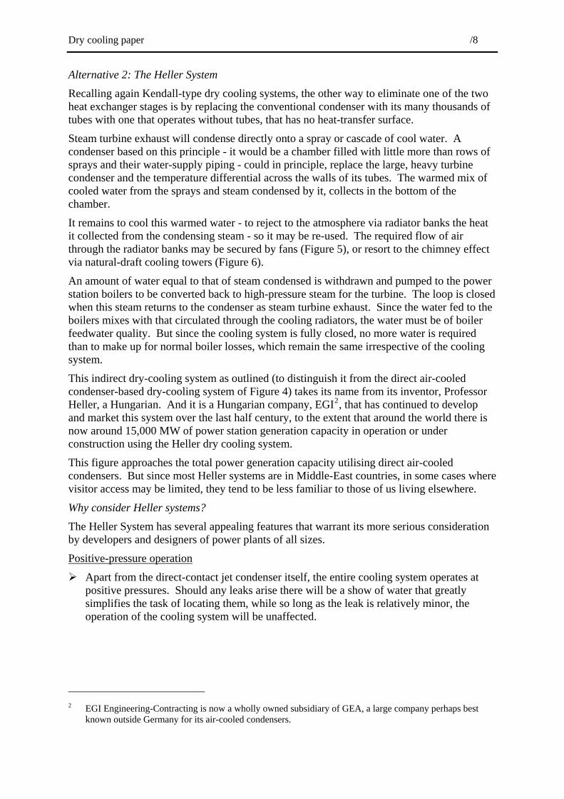
Trakya
The first plant visited lay a couple of hours’ drive west of Istanbul via the main motorway through this ancient region, Thrace--in Turkish Trakya, the name taken by the power station. It is the oldest of the three plants visited, dating back to the late 1980s. Rated at 1,200 MWe, when built it was at the forefront of combined-cycle power station design, with eight gas turbines and four steam turbines each rated at 100 MWe, arranged in two “blocks”. It provided an opportunity to see how Heller dry cooling systems were perforimng after a decade of continuous operation.
Recall that natural-draft cooling towers for dry cooling systems must be substantially larger than their evaporatively cooled counterparts because of the much greater amounts of air they must handle. So, since combined-cycle power stations are remarkably compact for their output, when approaching a power station such as Trakya it is the cooling towers that are first noticed, despite the absence of any plume (Figure 7).
The cooling towers, at 135 metres tall enough to accommodate a 30-story building, are indeed impressive, their radiator banks alone, are as tall as a six-storey building. These are mounted vertically, in “cooling deltas” – two sides of a triangle are taken up by radiator panels; the third, outward-facing side a set of louvres to control air flow through the panels. On this hot still day it was their quietness that impressed, a sound like wind in the treetops that could only be heard when far from the rest of the power station, even the switchyard, neither of which were particularly noisy.
Inside, the towers are substantially empty—they are, after all, just large chimneys. Air pressure makes it difficult to open an access door, but once through this, the blast of heat makes the hot summer air seem cool. Air inside the tower is around 20°C warmer again, the heat borne on an insistent dry wind—tangible evidence of the waste heat released when steam turbine exhaust condenses.
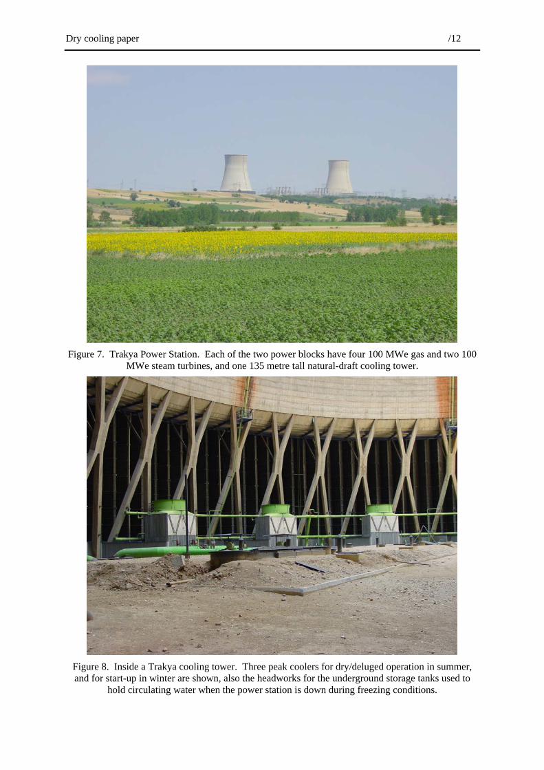
Other features become apparent: the large size of the piping and valves used to distribute water to and from the radiator banks; and, the below-ground tank system for accommodating the water should the radiator banks need to be drained in freezing weather. There are also the seemingly small dry-deluged coolers used in winter to preheat the air during start-up, and to trim, by evaporation, temperatures of returning water in summer to increase power output (Figure 8).
Back outside where it is cool enough to think once again, the power station operators say virtually no maintenance is required—every six months or so a blast of water is applied by a semi-portable spray system to the radiator banks to remove any dust.
Dry cooling paper /12
Figure 7. Trakya Power Station. Each of the two power blocks have four 100 MWe gas and two 100
MWe steam turbines, and one 135 metre tall natural-draft cooling tower.
Figure 8. Inside a Trakya cooling tower. Three peak coolers for dry/deluged operation in summer, and for start-up in winter are shown, also the headworks for the underground storage tanks used to
hold circulating water when the power station is down during freezing conditions.
Dry cooling paper /13
Bursa
As for Trakya, Bursa Power Station becomes apparent first by virtue of its pair of natural-draft cooling towers. Given its proximity to the main metropolitan area, its cooling towers, almost identical in size and duty to Trakya’s, generated some controversy during the planning stages of the project. Local opponents were not above issuing sketches of their concept of the towers, complete with vast black plumes erupting from them.
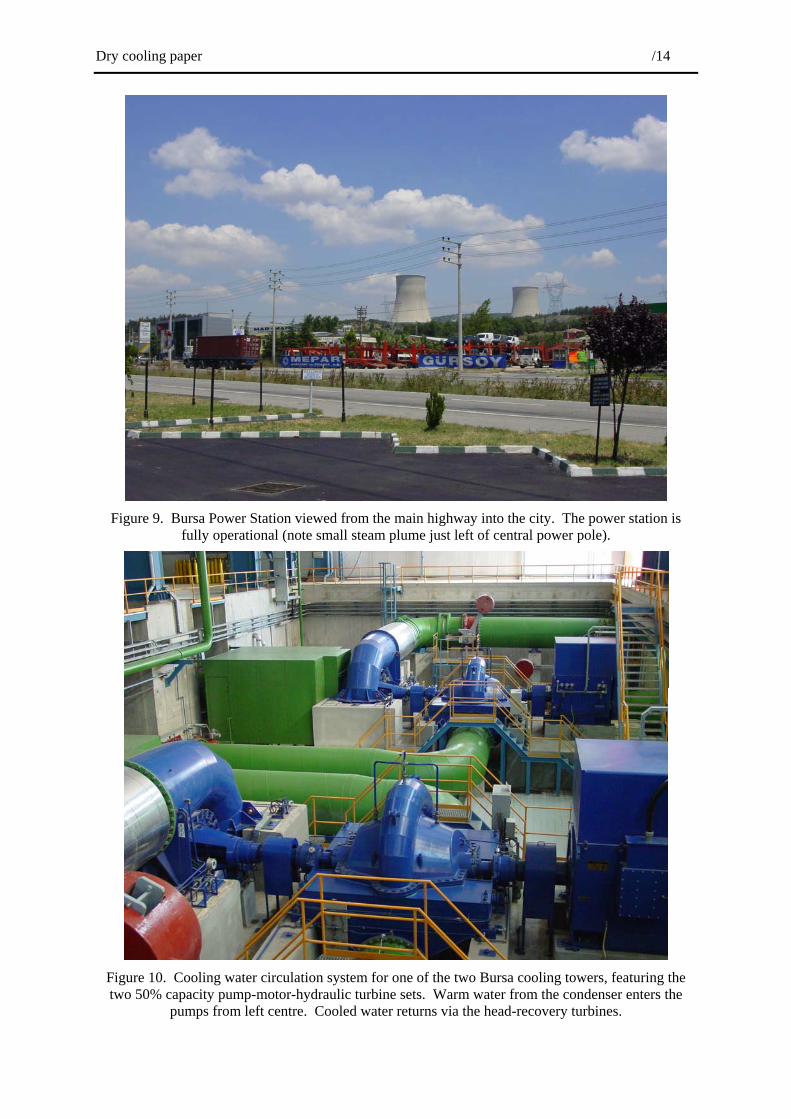
It lies little more than a kilometre from the main highway into the city from the north, yet because there are no plumes, nor noticeable noise, local residents have it seems, completely accepted the power station, towers and all; they no longer take any notice (Figure 9).
Bursa was completed a decade after Trakya, and reflecting improvements in gas turbine design in the interim, is rated at 1,400 MWe; 200 MWe more power for the same waste heat production. Each of its two “blocks” contain two large (240 MW) Mitsubishi gas turbines and one Mitsubishi steam turbine having a similar power output. Coming from Trakya we found much was familiar, but here, since each cooling tower handled one large rather than two smaller steam turbines, the pumps, piping and valves used to distribute water between the direct-contact condenser and cooling tower are even larger.
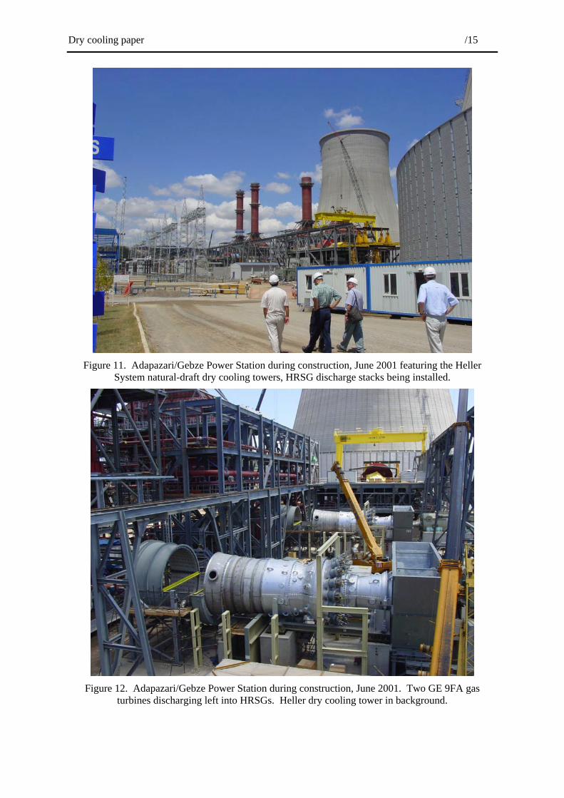
The arrangement is basically the same, however. The condenser, mounted immediately beneath the steam turbine, discharges its copious water flow via two 1.6 metre diameter pipes to a pair of pumps that raise its pressure sufficiently to ensure the entire system downstream remains at positive pressure. The cooled water from the tower returns to the condenser via a hydraulic turbine; this recovers useful work from the water as it flows under pressure to the condenser, which alone operates under vacuum. The pump, electric drive motor and hydraulic turbine are all arranged on a single shaft. Two such pump and turbine sets are installed below ground level in a pit adjacent to the condenser (Figure 10).
Gebze and Adapazari
A two-hour drive east of Istanbul took us to the third and newest power station; it is still under construction, the first of the three blocks due to be commissioned three months ahead of schedule in November 2001.
The power station with its three cooling towers is nestled in a valley to the north of the city of Adapazari (Figure 11). Gebze is in fact a town on the Sea of Marmara; we passed its turnoff soon after we left the outskirts of Istanbul. The developers of this is power station, InterGen (the power generation joint venture between Shell and Bechtel, who is also the EPC contractor) and its Turkish partner ENKA, originally intended it to be on two sites, Gebze and Adapazari. But following the massive earthquake in this region in the late 1990s, that intended for Gebze was moved adjacent to Adapazari.
Reflecting further advances in the state of the art even since Bursa, each of this power station’s three “blocks” are rated at 770 MWe, making it one of the world’s larger combined-cycle power stations, and arguably its most modern. Each block contains two General Electric Frame 9FA gas turbines rated at 260 MWe, plus one Alstom steam turbine with a similar rating. The natural-draft cooling towers are also the same size as those at Bursa and at Trakya, but with a few more cooling deltas.
Since it was still under construction it was possible to observe equipment before buildings, acoustic enclosures and the like fully obscured it. We could, for example, see clearly how the gas turbines exhaust into the heat-recovery steam generators (Figure 12), and relationships between each steam turbine, its direct-contact condenser, the cooling water pump pit, and the cooling tower itself (Figure 13).
Dry cooling paper /14
Figure 9. Bursa Power Station viewed from the main highway into the city. The power station is
fully operational (note small steam plume just left of central power pole).
Figure 10. Cooling water circulation system for one of the two Bursa cooling towers, featuring the two 50% capacity pump-motor-hydraulic turbine sets. Warm water from the condenser enters the
pumps from left centre. Cooled water returns via the head-recovery turbines.
Dry cooling paper /15
Figure 11. Adapazari/Gebze Power Station during construction, June 2001 featuring the Heller
System natural-draft dry cooling towers, HRSG discharge stacks being installed.
Figure 12. Adapazari/Gebze Power Station during construction, June 2001. Two GE 9FA gas
turbines discharging left into HRSGs. Heller dry cooling tower in background.

Dry cooling paper /16
To Hungary
While the hand of Communism rested relatively lightly upon Hungary, Matra well illustrates the changes the country has gone through since the Iron Curtain was drawn aside. Matra is an old lignite-fired power station rated at 800 MWe, located on a plain an hour’s drive east of Budapest within sight of the mountains of the same name. There were few emission controls—while electrostatic precipitators removed most of the dust, SOx and NOx emissions from this high-sulphur, low energy fuel went unchecked.
Matra Power Station was privatised in the early 1990s, sold to the big German utility RWE, who were required as a condition of the sale to install wet scrubbers. The solution RWE eventually adopted was to install one scrubber in each of the two larger natural-draft Heller-system cooling towers, each scrubber able to treat flue gases from 300 MW of generator capacity (Figure 14). The massive volumes of warm air rising from these cooling towers carry with them the water vapour-saturated scrubber effluent gases. The effect is to achieve a discharge height equivalent to that from a chimney many times taller, ensuring that any plumes are rapidly dispersed, never to lie near the ground on cold mornings as dense, acrid fogs.
Matra also afforded the opportunity of examining radiator elements that had been in operation for decades in what was until recently a highly polluted environment. There was no evident corrosion, although some that had been removed contained accumulations of silt.
A tour through EGI’s modern manufacturing facility, located not far from Matra, revealed that changes in design have been evolutionary rather than revolutionary—the cooling deltas being manufactured currently are clearly recognisable as being derived from those at Matra, but close examination reveals many improvements.
All wetted parts are of anodised aluminium. Oxide layers are further thickened to give additional protection to the metal in a bath of hot chromic acid. If the radiator banks are to be installed in a system where deluging is to be used they are given a further protective coating of an epoxy enamel. Radiator panels are shipped in 5-metre long container-compatible packs, ready for assembly on the power station site into 20-metre panels (Figure 15) for incorporation, following pressure testing and other checks, into the cooling tower (Figure 16).
A mechanical-draft installation
The final installation provided a change in that it was small, in a heavily built-up area in Budapest’s northern suburbs, and used fans to create the necessary draft of air.
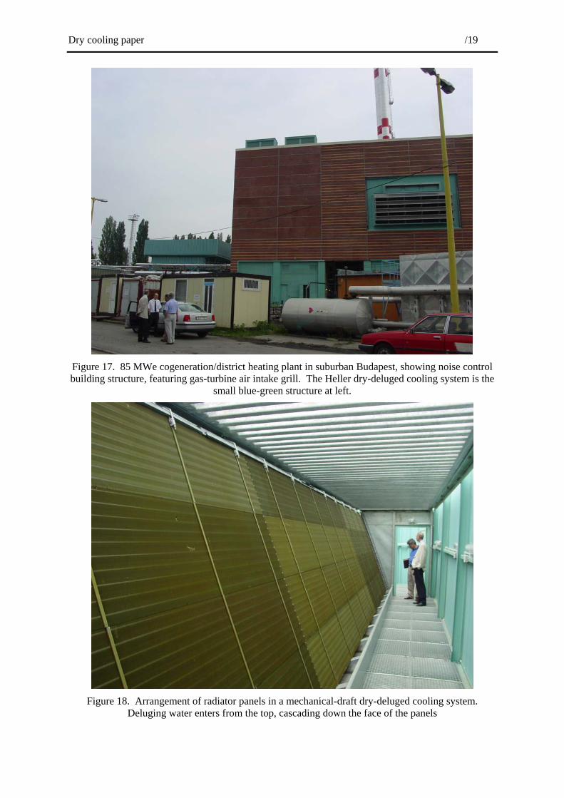
The modern, 85 MW combined-cycle power station shown in Figure 17 is used for district heating, the piped distribution of hot water to neighbouring dwellings for space heating in the winter. But in summer when the heat is not required it must be rejected to the environment, and a dry-deluged Heller system is used for this purpose. Water scarcity prompted resort to dry cooling, but enough water could be found to allow deluging to reduce the size of the cooling system to the area available within this extremely confined site. Figure 18 shows the horizontal arrangement of the cooling deltas, better to accommodate a cascade of water to enhance cooling by evaporation on hot summer days.
People in this affluent area of Budapest were expected to be no more inclined to welcome a power plant in their midst than their peers in any other city. The designers had to pay particular attention to noise, which explains the heavy masonry building housing the generation plant, and sound attenuation panels surrounding the cooling system’s draft fans—and these include some of the quietest ever specified.

Dry cooling paper /17
Figure 13. Equipment layout during Adapazari/Gebze Power Station construction: GE 9FA Gas
turbine at left discharging into HRSG at extreme left; steam turbine at top right, Heller System direct-contact condenser below, discharging to cooling water circulating system pump pit.
Figure 14. New wet FGD scrubber installed in natural-draft cooling tower at Matra Power Station,
Hungary. Stack gases enter from left via the 7-metre diameter red duct.

Dry cooling paper /18
Figure 15. Pressure-testing a cooling delta prior to installation in the cooling tower behind, Adapazari
Power Station. A panel support frame is at left.
Figure 16. Natural-draft cooling tower installation, showing radiator inlet and outlet water headers,
yet to be connected to cooling deltas by hose lengths.
Dry cooling paper /19
Figure 17. 85 MWe cogeneration/district heating plant in suburban Budapest, showing noise control building structure, featuring gas-turbine air intake grill. The Heller dry-deluged cooling system is the
small blue-green structure at left.
Figure 18. Arrangement of radiator panels in a mechanical-draft dry-deluged cooling system.
Deluging water enters from the top, cascading down the face of the panels
Dry cooling paper /20
Overall impressions
In this driest of continents, dry cooling deserves more serious consideration for handling the waste heat from thermal power stations of all sizes: large central power stations, as well as distributed through heavily built-up areas, or serving the needs of more remote communities.
If the site is able to accommodate it, a dry cooling system based around natural-draft cooling towers will definitely yield a lower sent-out cost of electricity, lower noise, and, if the flue gases are discharged into the centre of the cooling tower, better dispersion of stack gases. If there is some water, a Heller system with a deluging capacity could substantially close the performance gap with evaporative systems, to the point where retrofitting evaporative cooling systems without having to modify steam turbines, may become an option.
Dry cooling is a concept whose time has come—the technologies available, both the direct air-cooled condensers or the indirect Heller Systems featured in this paper, have stood the test of time. Dry cooling installations that have been in operation for decades have delivered almost as much power as would equivalent evaporative systems, but almost always with lower maintenance and operating costs. A fair accounting for the value of cooling water, one that takes into consideration the capital and operating costs of the dams, water treatment plants and reticulation systems required to deliver the water to the power station, may well tip the economic balance in favour of dry rather than evaporative cooling. Add the advantages of faster planning approvals through obviating the need to secure good water supplies and dispose of blowdown, and the comfort of knowing that that 100-year drought will not lead to conflicts with other water users, and the case for considering dry cooling becomes strong indeed.
Richard J Hunwick
August 2001
Acknowledgements
The writer greatly appreciates the time EGI staff made available to show him these installations. Further information on Heller systems may be obtained from EGI’s website: www.egi.hu.