roof tutorial - chief architect
TRANSCRIPT

1
Chapter 3:
Roof Tutorial
The first portion of this tutorial can be completed independent of the previous tutorials. We’ll go over some common roof styles that can be created using settings in the Wall Specification dialog. We’ll also learn how to add gables over doors and windows, how to create dormers automatically and manually, and how to create skylights. For additional information about using the Roof Tools, see “Roofs” on page 427 of the Reference Manual.
In this tutorial you’ll learn about:• Getting Started with Roofs• Deleting Roofs• Auto Rebuild Roofs• Hip Roofs• Gable Roofs• Shed Roofs• Saltbox Roofs• Gambrel Roofs• Gull Wing Roofs• Half Hip Roofs• Mansard Roofs• Finding the Start of an Upper Pitch• Roof Type Quick Reference• Roof Returns• Adding Gables over Doors and Windows
• Automatic Dormers• Manually Drawn Dormers• Skylights• Using the Break Wall Tool to Modify Roofs• Troubleshooting Automatic Roof Issues

2
Chief Architect X5 User’s Guide
Getting Started with RoofsTo gain a basic understanding of roofs and how they function with Chief Architect, we’ll begin this section of the tutorial with a new plan.
To begin a new plan1. If any plans are open, select File> Close All from the menu.
2. Select File> New Plan to open a new plan.
3. Select Build> Wall> Straight Exterior Wall and draw a rectangular floor plan, measuring about 34 feet by 24 feet (approximately 10.4 m by 7.3 m), in a clockwise direction. We’ll use this outline to build a number of different roof styles. See “Drawing Walls” on page 253.
Auto Rebuild Roofs Auto Rebuild Roofs is a convenient feature in Chief Architect that automatically rebuilds the roof in a plan whenever the exterior walls or floor/ceiling heights are changed. Auto Rebuild Roofs is turned off by default, and this tutorial is presented with this feature disabled; however the information presented here also applies when it is enabled.

Deleting Roofs
3
To turn on/off Auto Rebuild Roofs
1. Select Build> Roof> Build Roof from the menu.2. In the Build Roof dialog, check/uncheck Auto Rebuild Roofs and click OK.
Deleting RoofsWhether a roof was drawn manually or automatically generated, deleting roof planes is easy.
To delete a roof
1. Select Build> Roof> Delete Roof Planes .
• Select Edit> Delete Objects and in the Delete Objects dialog, select All Rooms On This Floor; place a check beside Roof Planes; and click OK.
If a warning message states that roofs cannot be deleted while Auto Rebuild Roof is on, click the Yes button to turn off Auto Rebuild Roof and delete the roof.
Hip RoofsWhen roofs are automatically generated, the default roof type is a hip roof, which means that a roof plane is built over every exterior wall in the plan that does not have another wall drawn above it.
To create a hip roof
1. Select Build> Roof> Build Roof from the menu to open the Build Roof dialog. The Pitch is set at 8 in 12 inches.

4
Chief Architect X5 User’s Guide
2. Check Build Roof Planes and click OK to generate a hip roof.
3. Select 3D> Create Perspective View > Full Overview to create a 3D overview of the
house. If you wish, you can select 3D> Toggle Textures from the menu to turn off the display of textures.
4. Select Window> Tile Vertically to see both views at the same time.

Gable Roofs
5
Gable RoofsIf you would like a gable over a particular wall rather than a roof plane bearing on it, you can specify it as a Full Gable Wall in the Wall Specification dialog.
To create a gable over a wall, specify it as a Full Gable Wall. To create basic gable roof, two walls must be specified as such.
To create a gable roof1. Click on the floor plan view window to make it the active view.
2. Select Build> Roof> Delete Roof Planes .
3. Click the Select Objects tool, select the vertical wall on the left, hold down the Shift key, and select the vertical wall on the right. The two walls should be group-selected.
4. Click the Open Object edit button and on the Roof tab of the Wall Specification dialog, check Full Gable Wall and click OK.

6
Chief Architect X5 User’s Guide
• Alternatively, you can click the Change to Gable Wall(s) edit button.• To remove the Full Gable Wall attribute from a wall, you can select it and click the
Change to Hip Wall(s) edit button.
5. Select Build> Roof> Build Roof to open the Build Roof dialog, check Build Roof Planes, and click OK.
Attic WallsWhen a roof is generated, attic walls are also generated. An attic wall fills the space between the first floor walls and angled roof planes above. To see this in floor plan view, take a look at the second floor.
If you do not want to see attic walls in floor plan view, you turn off their display.

Shed Roofs
7
To turn off the display of attic walls
1. In floor plan view, select Tools> Display Settings> Display Options (or press the ~ key) to open the Layer Display Options dialog.
2. Find Walls, Attic in the Name column, remove the check from the Disp column for this item, and click OK. For more information, see “Layer Display Options Dialog” on page 132 of the Reference Manual.
Shed RoofsTo create a single, sloping roof plane, or shed roof, two walls must be specified as Full Gable Walls, and one must be a High Shed/Gable Wall.
To create a shed roof1. Click on the floor plan view window to make it the active view.
2. Select Build> Roof> Delete Roof Planes .
3. With the Select Objects tool, double-click the lower horizontal wall and in the Roof tab of the Wall Specification dialog, check High Shed/Gable Wall and click OK.
4. As in the Gable Roof example, specify the left and right vertical walls as Full Gable Walls.
5. Select Build> Roof> Build Roof to open the Build Roof dialog, check Build Roof Planes, and click OK.

8
Chief Architect X5 User’s Guide
Saltbox RoofsA saltbox is a type of gable roof with different pitches on each of the two roof planes and an offset ridge. Assign a different pitch to the two roof planes in the Wall Specification dialog for the wall supporting each one.
To create a saltbox roof1. Click on the floor plan view window to make it the active view.
2. Select Build> Roof> Delete Roof Planes .
3. With the Select Objects tool, double-click the lower horizontal wall. On the Roof tab of the Wall Specification dialog, remove the check from High Shed/Gable Wall and change the pitch to 12 in 12. Click OK to close the Wall Specification dialog.
4. Leave the Full Gable Wall box checked for the two vertical walls.
5. Select Build> Roof> Build Roof to open the Build Roof dialog, check Build Roof Planes, specify the pitch as 3 in 12, and click OK.
Gambrel RoofsA gambrel or barn style roof has two pitches on each side of the ridge. The first (lower) pitch on either side is steeper than the pitch near the ridge.

Gambrel Roofs
9
To create a gambrel roof1. Click on the floor plan view window to make it the active view.
2. Select Build> Roof> Delete Roof Planes .3. Group select the horizontal walls and open them for specification. On the Roof tab:
• Specify the lower Pitch as 12 in 12. • Place a check in the box beside Upper Pitch.• Keep the Upper Pitch as 6 in 12 and change the Start Height to 156.• To learn more, see “Finding the Start of an Upper Pitch” on page 80.
4. Click OK to close the Wall Specification dialog. 5. The two vertical walls should remain Full Gable Walls.6. Open the Build Roof dialog, check Build Roof Planes, specify the Pitch as 6 in 12 once
again, and click OK.
Experiment with alternate pitches and overhangs. Also, try varying the height at which the second pitch begins so that you can see the effect it has on your gambrel roof design.

10
Chief Architect X5 User’s Guide
Gull Wing RoofsA gull wing roof has two pitches on either side of the ridge, as a gambrel does; but the first pitch of a gull wing is shallower than the second.
To create a gull wing roof1. Click on the floor plan view window to make it the active view.
2. Select Build> Roof> Delete Roof Planes .3. Change the following settings for each of the horizontal walls on the Roof tab of the Wall
Specification dialog:
• Specify the lower Pitch as 3 in 12. • Place a check in the box beside Upper Pitch.• Keep the Upper Pitch as 12 in 12 and change the Start Height to 125".• To learn more, see “Finding the Start of an Upper Pitch” on page 80.
4. The two vertical walls remain Full Gable Walls.
5. Click the Build Roof tool, check Build Roof Planes, and click OK in the Build Roof dialog.

Half Hip Roofs
11
Experiment with the height at which the second pitch begins so that you can see the effect it has on your gull wing roof design.
Half Hip RoofsA half hip roof has two gable ends. At the top of each gable is a small hip that extends to the ridge.
To create a half hip roof1. Click on the floor plan view window to make it the active view.
2. Select Build> Roof> Delete Roof Planes .
3. With the Select Objects tool, double-click each wall and make these changes on the Roof tab of the Wall Specification dialog:For the two Horizontal walls:
• Specify the lower Pitch as 6 in 12. • Uncheck the box beside Upper Pitch.

12
Chief Architect X5 User’s Guide
For the two Vertical walls:
• Leave the Full Gable Wall box checked.• Check the box beside Upper Pitch.• Specify the Upper Pitch as 3 in 12 and set the Start Height at 170".
4. Click the Build Roof tool, check Build Roof Planes, and click OK in the Build Roof dialog.
Mansard RoofsA mansard roof is a hip roof with two slopes on the roof sections above each of the four walls. The second slope begins at the same height above each wall. The upper slope is usually quite gentle and the lower slope, much steeper.
Mansard Roofs
13
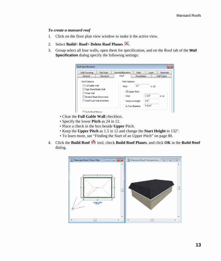
To create a mansard roof1. Click on the floor plan view window to make it the active view.
2. Select Build> Roof> Delete Roof Planes .3. Group select all four walls, open them for specification, and on the Roof tab of the Wall
Specification dialog specify the following settings:
• Clear the Full Gable Wall checkbox.• Specify the lower Pitch as 24 in 12. • Place a check in the box beside Upper Pitch.• Keep the Upper Pitch as 1.5 in 12 and change the Start Height to 132". • To learn more, see “Finding the Start of an Upper Pitch” on page 80.
4. Click the Build Roof tool, check Build Roof Planes, and click OK in the Build Roof dialog.

14
Chief Architect X5 User’s Guide
Finding the Start of an Upper Pitch When creating a roof style with lower and upper pitches, you can determine the exact Starts at or In From Baseline values that you need in an elevation view.
To find the start of an upper pitch 1. Generate the roof using only the first, lower pitch. Be sure to define all the roof
information for each wall (gable, hip, first pitch, etc.).2. Create a cross section view that includes the roof plane that will have the second pitch. See
“Cross Section/Elevation Views” on page 833.
3. Select CAD> Points> Place Point , click to place a temporary point near the location where you want the second pitch to start, and then either:
• Using the Point-to-Point Dimension tool, drag a dimension line from the floor on Floor 1 (which has a height of 0 by default) to the temporary point.
• Using the Point-to-Point Dimension tool, drag a dimension line from the baseline to the vertical plane of the temporary point.
4. Enter either of these values in the Wall Specification dialog. You can press the Tab key to update the other value. Click OK to close the dialog.
5. Open the Build Roof dialog, check Build Roof Planes and click OK to rebuild the roof.

Roof Type Quick Reference
15
Roof Type Quick ReferenceThe following chart provides a quick reference for building the roof styles described in this tutorial. The chart shows which walls to change and what to change on the Roof tab of the Wall Specification dialog for each wall. These parameters are based on a 34x24-foot model. For different size plans, adjust these numbers.
Roof Type Wall to Change
Set as Full
Gable
Set as High Shed Gable
Lower Pitch
Upper Pitch
Start Height
GableRoof
Vertical Wall 1Vertical Wall 2Horizontal Wall 1 XHorizontal Wall 2 X
ShedRoof
Vertical Wall 1 XVertical Wall 2 XHorizontal Wall 1 XHorizontal Wall 2
SaltboxRoof
Vertical Wall 1 XVertical Wall 2 XHorizontal Wall 1 12 in 12Horizontal Wall 2 3 in 12
GambrelRoof
Vertical Wall 1 XVertical Wall 2 XHorizontal Wall 1 12 in 12 6 in 12 156Horizontal Wall 2 12 in 12 6 in 12 156
Gull WingRoof
Vertical Wall 1 XVertical Wall 2 XHorizontal Wall 1 3 in 12 12 in 12 125Horizontal Wall 2 3 in 12 12 in 12 125
Half HipRoof
Vertical Wall 1 X 3 in 12 170Vertical Wall 2 X 3 in 12 170Horizontal Wall 1 6 in 12Horizontal Wall 2 6 in 12
MansardRoof
Vertical Wall 1 12 in 12 1.5 in 12 132Vertical Wall 2 12 in 12 1.5 in 12 132Horizontal Wall 1 12 in 12 1.5 in 12 132Horizontal Wall 2 12 in 12 1.5 in 12 132

16
Chief Architect X5 User’s Guide
Roof ReturnsA roof return is a small decorative roof plane that connects to the low side of a gable roof overhang and extends below the upper triangular portion of the gable wall. While you can build these manually, the following pictures illustrate the three styles of roof returns that can be produced automatically in Chief Architect.
The first two are called Gable and Hip returns, since the returns themselves end in either a gable or a hip. The third is called a Full return because it extends under the entire gable, connecting both sides. Full roof returns are sometimes referred to as water tables.
The Roof tab of the Wall Specification dialog contains the settings that generate roof returns. Roof returns can be specified for any wall, but only exterior Full Gable Walls can display them.
Specify the horizontal Length of the returns in inches; the distance to Extend the returns past the main roof overhang; the style of roof return; and whether the returns are sloping or flat. As long as your model has a roof, the specified roof returns will be generated when you click OK. For more information, see “Roof Returns” on page 480 of the Reference Manual.
Gable Return Hip Return Full Return

Adding Gables over Doors and Windows
17
Adding Gables over Doors and WindowsYou can add a gable roof over a door or window.
To create a gable roof over a door or window
1. Select a door or window, then click the Gable Over Door/Window edit button.
2. Click the Build Roof tool, check Build Roof Planes, and click OK in the Build Roof dialog.
3. A gable is created with an overhang of one foot on each side of the door or window.
To remove a gable roof over a door or window
1. Select the door or window and click the Delete Gable Over Opening edit button.
2. Click the Build Roof tool, check Build Roof Planes, and click OK in the Build Roof dialog.
3. When you rebuild the roof, the gable will be removed.
To create a gable over several doors and/or windows1. Select a door, window, or mulled unit.1. Hold down the Shift key and click on additional doors and/or windows to add them to your
selection set.
2. Click the Gable Over Door/Window edit button.
3. Click the Build Roof tool, check Build Roof Planes, and click OK in the Build Roof dialog to create a gable over the selected wall openings.

18
Chief Architect X5 User’s Guide
Automatic DormersThe Auto Dormer and the Auto Floating Dormer tools offer a quick and convenient alternative to drawing dormers manually. With just a few clicks an entire dormer is placed, complete with roof, roof hole, walls, and window.
There is a limit to how low the roof pitch can be set when creating dormers. Generally, 9 in 12 is the lowest pitch that will provide enough elevation to contain a dormer.
Auto Floating Dormer
An Auto Floating Dormer can be placed anywhere within a roof plane, as long as there is enough space to contain it. A floating dormer is what some people refer to as a “decorative” dormer. It does not require support walls and does not tie in with the structure of the building.
Select Build> Roof> Build Roof> Auto Floating Dormer and click within an existing roof plane to place a floating dormer at that location. Once a dormer is created, it can be moved, resized and opened for specification. For more information, see “Editing Auto Dormers” on page 477 of the Reference Manual.
An Auto Floating Dormer cannot initially be placed so that its wallsalign with an exterior wall. Once it is created, its front wall can often
be aligned with an exterior wall below; however, its side walls must remaininside the exterior walls.

Manually Drawn Dormers
19
Auto Dormer
The Auto Dormer tool places a standard dormer, which has the same space and structural requirements as a manually drawn dormer. If you have not drawn dormers manually, you may benefit from learning how. For information, see “Manually Drawn Dormers” on page 85.
• Dormers can only be placed in roofs that are large and steep enough to contain them. You may need to change the pitch and/or size of a roof plane before an automatic dormer can be placed. If a warning message stating that some walls are outside the roof plane appears when you try to place an automatic dormer, try decreasing the Height value in the Dormer Defaults dialog.
• A knee wall must be present for the dormer to connect to. A knee wall will create attic space and offer structural support. A wall must be present, but it does not necessarily have to be designated as a Knee Wall in the Wall Specification dialog.
• Dormers cannot be in conflict with the ceiling on the same floor. If you need to create an open, attic condition, check Ignore Top Floor in the Build Roof dialog and generate roof planes based on the floor below the dormer. If necessary, you can then use Raise Off Plate in the Build Roof dialog to move roof planes up. See “Build Roof Dialog” on page 434 of the Reference Manual.
Once placed in your model, an automatic dormer can be repositioned and its width adjusted using its edit handles. Double-click on an automatic dormer to open the Dormer Specification dialog, which looks just like the Dormer Defaults dialog but only affects the selected dormer. You can also select the dormer window separately; resize it with its edit handles; and open it for specification. For more information about dormers, see “Dormers and Crickets” on page 475 of the Reference Manual.
Manually Drawn DormersTo create dormers in an upper floor, create a new floor for your plan and modify this floor with knee walls and windows to form gables. We’ll start with a new 40 x 30 foot plan to learn this technique.
As with automatic dormers, roof pitches of 9 in 12 or greater generally work better than shallow pitches when creating dormers because they provide enough vertical space to build the dormer within.
To create a new plan1. Select File> Close All from the menu to close any open plans.
2. Select File> New Plan to open a new plan. In the Create New Plan dialog, select the Default Style template.

20
Chief Architect X5 User’s Guide
3. Select Build> Wall> Straight Exterior Wall and draw a rectangular floor plan, 40 feet by 30 feet, in a clockwise direction.
4. Click the Fill Window Building Only button to zoom in on the house.
5. Select File> Save from the menu, save the file to an easy to find location, such as Documents, and give the plan a name.
6. Group select the right and left vertical walls, open them for specification, and on the Roof tab of the Wall Specification dialog, click the Full Gable Wall check box and click OK.
7. Select Build> Floor> Build New Floor .8. Check the Derive new 2nd floor plan from 1st floor plan option in the New Floor dialog
and click OK to display the Floor 2 Defaults dialog. Leave these settings at their default for now and click OK.

Manually Drawn Dormers
21
9. Select Build> Roof> Build Roof , check Build Roof Planes, change the pitch to 12 in 12, and click OK in the Build Roof dialog.
To create two knee walls
A knee wall is a short wall on an upper floor that is cut off by a roof plane.
1. Select Build> Wall> Straight Interior Wall and draw a horizontal interior wall (from left to right). Position this knee wall so that it is 5 feet from the top exterior wall.
2. Draw another interior wall (from right to left) and position it 5 feet from the bottom exterior wall. You can reposition the knee walls using dimensions. For more information, see “Moving Objects Using Dimensions” on page 932 of the Reference Manual.
You can also create a custom wall type for the knee walls, such as awall with only a framing layer and one sheetrock layer. See “Wall
Type Definitions Dialog” on page 279 of the Reference Manual.

22
Chief Architect X5 User’s Guide
3. Group select both interior walls and open them for specification. Check Knee Wall on the Roof tab of the Wall Specification dialog and click OK.
4. Select CAD> Dimensions> Automatic Exterior Dimensions to create exterior dimension lines for your plan, which should now look like this:

Manually Drawn Dormers
23
To build the dormer walls
1. Select Build> Wall> Straight Exterior Wall and draw two rectangular boxes on the outside of the lower interior wall, as shown in the following image.
2. Position the lower walls of each dormer box 2 feet from the bottom wall. The lower dormer walls are those parallel to the bottom wall.
3. Edit each dormer box so that it is 6 feet from each vertical side wall and 8 feet wide.
4. Select Build> Wall> Break Wall and click along the lower interior wall to place wall breaks as indicated in center of each overall in the following image.

24
Chief Architect X5 User’s Guide
5. Delete the upper, horizontal portion of each window box.
To add a window to each dormer
1. Select Build> Window> Window and click on each dormer front wall to place a window. The program may warn you that you are adding windows to an interior wall; click OK to continue.
2. Select the window; click the Center Object edit button; and click near the wall containing the window to center it on the wall. See “Using Center Object” on page 209 of the Reference Manual.
3. Do the same for the other window.
To build the roof1. Group select the two dormer front walls that contain a window, open them for
specification, and on the Roof tab of the Wall Specification dialog, check Full Gable Wall and click OK.
2. Group select the dormer side walls, open them for specification, and on the Roof tab of the Wall Specification dialog, specify the Pitch for the dormer roof plane above the wall, and click OK. Earlier we specified a pitch of 12 in 12 in the Build Roof dialog, that pitch should have prefilled here. A steep pitch of 12 in 12 will work well for these dormers.
3. Double-click the narrow room above the top knee wall to open the Room Specification dialog, designate its Room Type as “Attic” and click OK.
4. Do the same for the lower attic room.

Manually Drawn Dormers
25
5. Select Build> Roof> Build Roof from the menu. 6. In the Build Roof dialog, check Build Roof Planes, and click OK.7. Create a 3D view to see the results.
8. Notice there are small gaps in the dormer side walls. This gap is caused by the difference between the position of the knee walls and the point at which the ceiling intersects the roof plane. This location is marked by the black dotted line in floor plan view.

26
Chief Architect X5 User’s Guide
9. Select each of the knee walls and move them back so that they are in alignment with the
ceiling plane. When Object Snaps are enabled, the walls will snap into position when they are close to the ceiling lines.

Crickets and Dormer Vents
27
10. Take a look in a 3D view.
You can move the interior walls closer to or further from the outside walls to change the dormers’ elevation, or change the pitch for the roof to make the dormers longer. You can create dormers in more complex plans the same way, but you may want to experiment with wall placement and pitch to achieve the desired effect.
Crickets and Dormer VentsRoof crickets, sometimes called saddles, are raised roof planes built to divert water or snow. When a roof is generated automatically, crickets will not be produced, but they can be drawn
manually using the Roof Plane tool.
Dormer vents can be created using a similar technique.
To create a manually drawn chimney cricket1. Create a basic rectangular structure with a hip roof. See “To create a hip roof” on page 69.
• In this example, the display of Roof Plane Labels is turned off. See “Roof Plane Labels” on page 445 of the Reference Manual.
2. Select Build> Fireplace and click on one of the exterior walls to place a masonry fireplace at that location in the wall.

28
Chief Architect X5 User’s Guide
• Midpoint Object Snaps or the Center Objects edit tool can be used to center the fireplace along the wall, if desired. See “Using Center Object” on page 209 of the Reference Manual.
3. Make any required changes to the fireplace.
• In this example, the default 48" wide fireplace is used, but its Depth edit handle is used to offset the fireplace 6" towards the exterior. See “Fireplaces” on page 741 of the Reference Manual.
4. Select CAD> Line> Draw Line and draw a CAD line along the inside surface of the fireplace’s firebox.

Crickets and Dormer Vents
29
• You can also draw the CAD line near the desired location and then move it into place using dimensions. See “Moving Objects Using Dimensions” on page 932 of the Reference Manual.
• Make sure that the CAD line extends past the fireplace in both directions.
5. Select Build> Roof> Build Roof from the menu, and in the Build Roof dialog, specify the Pitch, Framing, and any other attributes that you will need for the cricket.
• In this example, a Pitch of 12:12 and 1 1/2" x 5 1/2" rafters are specified. See “Build Roof Dialog” on page 434 of the Reference Manual.
• Do not check Build Roof Planes. Here, we’re using the Build Roof dialog to set the defaults for manually drawn roof planes. See “Roof Defaults” on page 429 of the Reference Manual.
6. Select Build> Roof> Roof Plane from the menu, then:
• Click on the CAD line near one of its endpoints and drag to draw a roof baseline perpendicular to the line, towards the structure’s interior.
• Release the mouse button and move the mouse parallel to the CAD line and in the direction of the fireplace’s center and click once.

30
Chief Architect X5 User’s Guide
• The roof plane that is created will draw its height from the top of the roof below at the point where you first clicked to begin drawing.
7. Use dimensions to resize the new roof plane so that it measures half the width of the fireplace from its low edge to its ridge. In this example, that distance is 24".
8. Use Roof Intersection Points to find the intersection point for the edge of the roof plane opposite the fireplace. See “Locating Intersections” on page 448 of the Reference Manual.
• If the program creates an Intersection Point that is not located on the roof plane edge, move that edge so that it is closer to the fireplace and the roof plane is more narrow and try again..
9. Use the roof plane’s edit handles to:• Angle the low edge of the roof plane up to the Intersection Point.
• Drag the short edge of the roof plane outward until it disappears and the roof plane becomes a triangle.
Note: In this example, the cricket roof plane is assigned an angled fill pattern tomake it easier to see.
Crickets and Dormer Vents
31
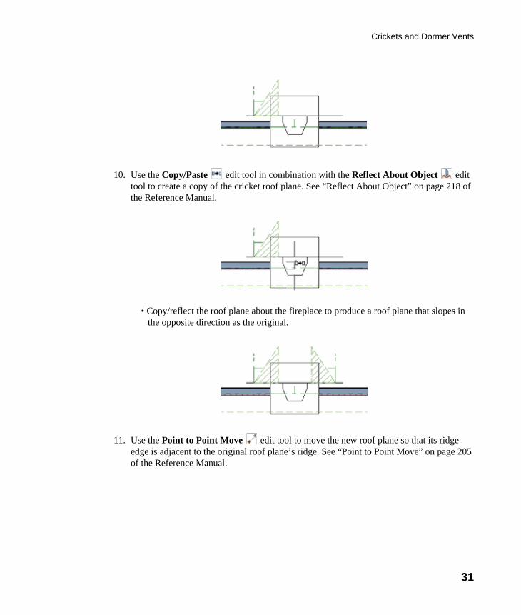
10. Use the Copy/Paste edit tool in combination with the Reflect About Object edit tool to create a copy of the cricket roof plane. See “Reflect About Object” on page 218 of the Reference Manual.
• Copy/reflect the roof plane about the fireplace to produce a roof plane that slopes in the opposite direction as the original.
11. Use the Point to Point Move edit tool to move the new roof plane so that its ridge edge is adjacent to the original roof plane’s ridge. See “Point to Point Move” on page 205 of the Reference Manual.

32
Chief Architect X5 User’s Guide
12. Center the cricket behind the fireplace:• Shift+select the two cricket roof planes.
• Click the Center Objects edit button.
• Move the mouse pointer over the fireplace. When a center axis displays over the fireplace, click once.
13. Create a 3D view to see the results.

Crickets and Dormer Vents
33
The cricket created above can easily be converted into a dormer vent. Begin by closing the 3D view and returning to floor plan view.
To create a dormer vent
1. Select the fireplace positioned in front of the cricket and click the Delete button.
2. Go Up One Floor and select Tools> Display Settings> Reference Display .
3. Select Build> Wall> Exterior Wall and draw a wall inside the area of the roof cricket on the floor below, parallel to its front.
• If you draw the wall in the wrong direction and its siding layer faces the interior, select
it and click the Reverse Layers edit button.
Remember to restore the settings in the Build Roof dialog if you intend to drawmore structural roof planes in your plan.
34
Chief Architect X5 User’s Guide
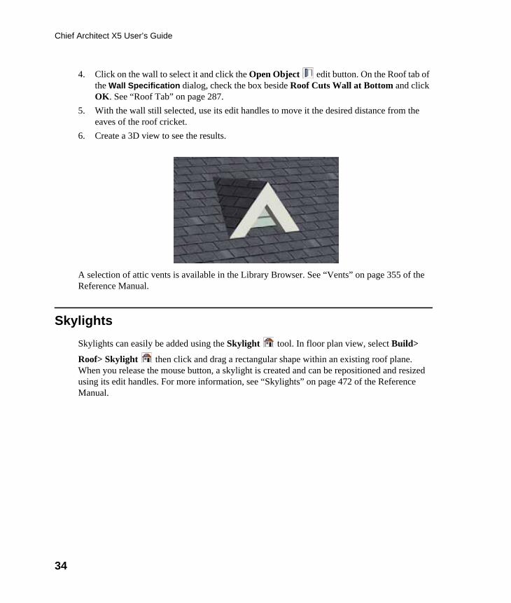
4. Click on the wall to select it and click the Open Object edit button. On the Roof tab of the Wall Specification dialog, check the box beside Roof Cuts Wall at Bottom and click OK. See “Roof Tab” on page 287.
5. With the wall still selected, use its edit handles to move it the desired distance from the eaves of the roof cricket.
6. Create a 3D view to see the results.
A selection of attic vents is available in the Library Browser. See “Vents” on page 355 of the Reference Manual.
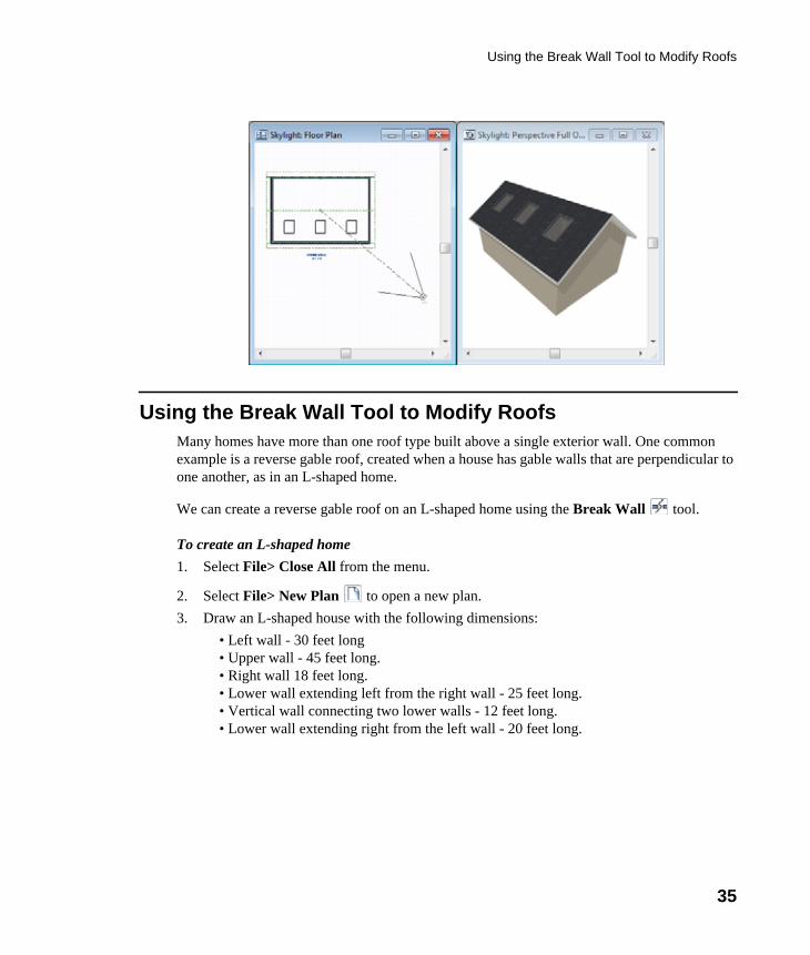
SkylightsSkylights can easily be added using the Skylight tool. In floor plan view, select Build>
Roof> Skylight then click and drag a rectangular shape within an existing roof plane. When you release the mouse button, a skylight is created and can be repositioned and resized using its edit handles. For more information, see “Skylights” on page 472 of the Reference Manual.
Using the Break Wall Tool to Modify Roofs
35
Using the Break Wall Tool to Modify RoofsMany homes have more than one roof type built above a single exterior wall. One common example is a reverse gable roof, created when a house has gable walls that are perpendicular to one another, as in an L-shaped home.
We can create a reverse gable roof on an L-shaped home using the Break Wall tool.
To create an L-shaped home1. Select File> Close All from the menu.
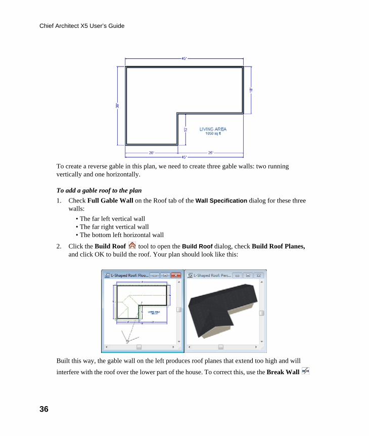
2. Select File> New Plan to open a new plan.3. Draw an L-shaped house with the following dimensions:
• Left wall - 30 feet long• Upper wall - 45 feet long.• Right wall 18 feet long.• Lower wall extending left from the right wall - 25 feet long.• Vertical wall connecting two lower walls - 12 feet long.• Lower wall extending right from the left wall - 20 feet long.
36
Chief Architect X5 User’s Guide
To create a reverse gable in this plan, we need to create three gable walls: two running vertically and one horizontally.
To add a gable roof to the plan1. Check Full Gable Wall on the Roof tab of the Wall Specification dialog for these three
walls:• The far left vertical wall• The far right vertical wall• The bottom left horizontal wall
2. Click the Build Roof tool to open the Build Roof dialog, check Build Roof Planes, and click OK to build the roof. Your plan should look like this:
Built this way, the gable wall on the left produces roof planes that extend too high and will
interfere with the roof over the lower part of the house. To correct this, use the Break Wall

Using the Break Wall Tool to Modify Roofs
37
tool to break the left wall into two different sections. We can then specify the upper section as Full Gable without affecting the lower section.
To use the Break Wall tool
1. Select Build> Wall> Break Wall and click the far left wall at a point even with the lower right wall. Extension snaps should help you place the break at the right place. See “Extension Snaps” on page 147 of the Reference Manual.
2. Open the lower portion of the wall for specification and on the Roof tab of the Wall Specification dialog, clear the Full Gable Wall checkbox and click OK.
3. Click the Build Roof tool, check Build Roof Planes, and click OK to build a roof based on the new wall specifications.
You now have two full gable roof sections meeting to form your L-shaped roof. Your plan should look like the following image:

38
Chief Architect X5 User’s Guide
Notice the step in the ridge line. This can be corrected by resizing the lower gable wall. Select the vertical wall to the right of the bottom gable wall and move it to the left 2 feet, reducing the length of the gable wall from 20 to 18 feet. When you are finished, rebuild the roof.
This completes this Roof Tutorial. You can use any combination of the techniques described here to create a wide variety of roof planes. Let’s return to our Stucco Beach House plan and apply what we have learned.
Adding a RoofNow that we have a basic understanding of the automatically roof tools, let’s return to our previously saved Stucco Beach House plan, as it looks like our house could use a roof now.
Let’s select File> Save As and give this plan a new name, such as "Beach House Roof Tutorial" before continuing.
To edit the default roof1. Close any other views you may still have open. For the following steps, only the floor plan
view should be open.
2. Starting on Floor 1, we will start by using the Select Objects tool to select the top horizontal exterior Kitchen wall, as indicated in the image below.

Adding a Roof
39
3. Click on the Open Object edit button to display the Wall Specification dialog, go to the Roof tab, place a checkmark in the Full Gable Wall option, and click OK.
4. Click Up One Floor to go to the second floor.
5. Using the Select Objects tool, select the Balcony room, then click on the he Open
Object edit button to open the Room Specification dialog, and on the Structure tab, uncheck Roof Over this Room if it is selected, then click OK.
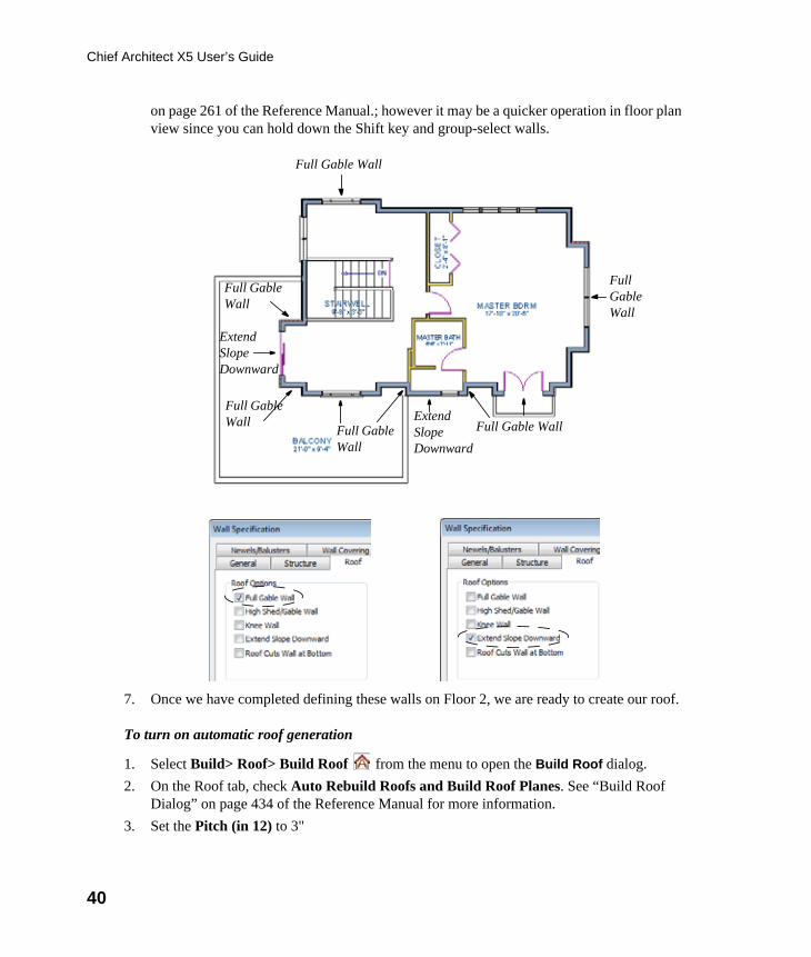
6. Open the following second floor walls’ specification dialogs and assign the settings shown in the following image on the Roof tab of the Wall Specification dialog. See “Roof Tab” on page 287 of the Reference Manual.
Individual walls can be selected and edited in both 2D and 3D views. See “Editing Walls”
40
Chief Architect X5 User’s Guide
on page 261 of the Reference Manual.; however it may be a quicker operation in floor plan view since you can hold down the Shift key and group-select walls.
7. Once we have completed defining these walls on Floor 2, we are ready to create our roof.
To turn on automatic roof generation
1. Select Build> Roof> Build Roof from the menu to open the Build Roof dialog.2. On the Roof tab, check Auto Rebuild Roofs and Build Roof Planes. See “Build Roof
Dialog” on page 434 of the Reference Manual for more information.3. Set the Pitch (in 12) to 3"
Full Gable Wall
Full Gable Wall
Full Gable Wall
Full Gable Wall
Extend Slope Downward
Extend Slope Downward
Full Gable Wall
Full Gable Wall

Adding a Roof
41
4. You can go to the Materials tab to change the material of your roof, where we will choose an Earth Roof Tile material.
5. Click OK to close the dialog and generate a roof.6. Recall that the additional walls you now see displayed are attic walls.
42
Chief Architect X5 User’s Guide
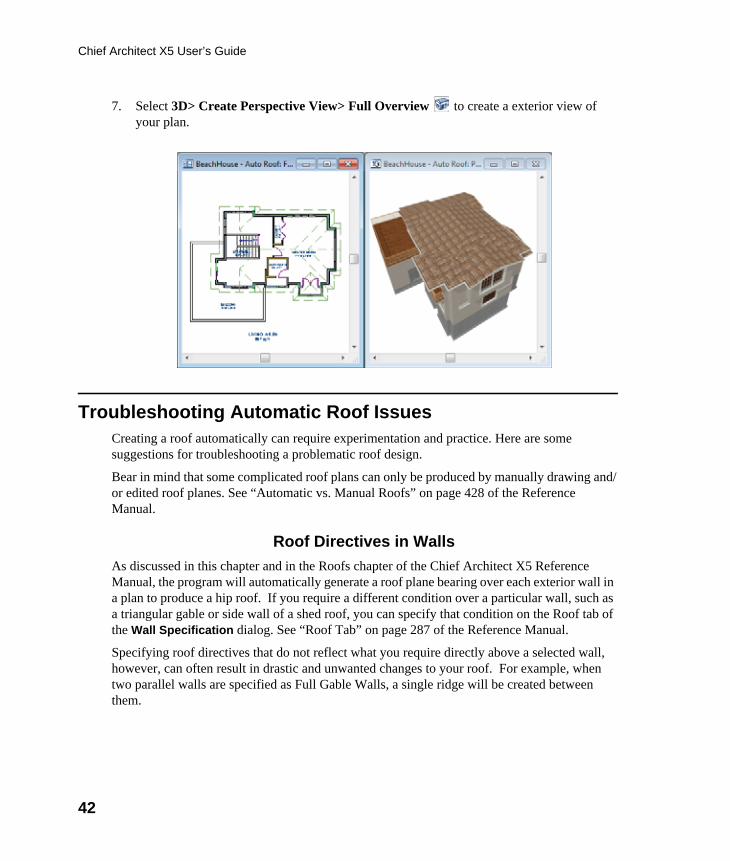
7. Select 3D> Create Perspective View> Full Overview to create a exterior view of your plan.
Troubleshooting Automatic Roof IssuesCreating a roof automatically can require experimentation and practice. Here are some suggestions for troubleshooting a problematic roof design.
Bear in mind that some complicated roof plans can only be produced by manually drawing and/or edited roof planes. See “Automatic vs. Manual Roofs” on page 428 of the Reference Manual.
Roof Directives in WallsAs discussed in this chapter and in the Roofs chapter of the Chief Architect X5 Reference Manual, the program will automatically generate a roof plane bearing over each exterior wall in a plan to produce a hip roof. If you require a different condition over a particular wall, such as a triangular gable or side wall of a shed roof, you can specify that condition on the Roof tab of the Wall Specification dialog. See “Roof Tab” on page 287 of the Reference Manual.
Specifying roof directives that do not reflect what you require directly above a selected wall, however, can often result in drastic and unwanted changes to your roof. For example, when two parallel walls are specified as Full Gable Walls, a single ridge will be created between them.

Troubleshooting Automatic Roof Issues
43
If a wall that is perpendicular to these walls is also specified as a Full Gable Wall, the roof becomes more complex with an additional ridge, two valleys, and two hips.
If you are seeing hips or valleys in your roof where you do not expect them, revisit the Roof tab of the walls supporting the affected roof planes.
Roof HeightsThe heights of all automatically generated roof planes are based on the heights of the walls that they bear on. Wall heights, in turn, are determined by the ceiling heights of the rooms that they define. See “Floor & Ceiling Heights” on page 311 of the Reference Manual.
For example, the hip roof over a simple rectangular structure with a consistent ceiling heights (in this case, 109 1/8") has four roof planes.

44
Chief Architect X5 User’s Guide
This roof will become considerably more complex if one room inside is given a lowered ceiling height (in this case, 97 1/8").
If you generate a roof and it seems to be more complicated and has more roof planes than it should, take a look at the ceiling heights of the rooms in the plan. Often, the correct way to

Troubleshooting Automatic Roof Issues
45
create a lowered ceiling condition will be to set the ceiling at the default height create a lowered Ceiling Finish. See “Lowered Ceilings” on page 313 of the Reference Manual.
Controlling Roof RidgesA single roof ridge will generate for as long as the bearing walls that support the roofs on either side of the ridge are the same distance apart. When alcoves or bumpouts are introduced along either bearing wall, the ridge is likely to become broken.
For example, a simple rectangular structure with Full Gable Walls at each end generates a roof with a ridge that runs from Full Gable Wall to Full Gable Wall.
If a bumpout is added that affects the length of either Full Gable Wall, or if an alcove is added anywhere along the length of the structure, the ridge will no longer follow a straight line.
There are a number of ways to maintain a single ridgeline in the presence of alcoves or bumpouts:
• Use the Break Wall tool to control the length of a Full Gable Wall section. See “Using the Break Wall Tool to Modify Roofs” on page 101.

46
Chief Architect X5 User’s Guide
• Increase the Minimum Alcove Size to specify what size alcoves are roofed. See “Roof Tab” on page 435 of the Reference Manual.
• Use the Extend Slope Downward roof directive to allow the roof over a bumpout to extend lower then the ceiling height in that area. See “Roof Directives in Walls” on page 270 of the Reference Manual.
• Specify the area inside of an alcove as an "Open Below" room with a roof but no ceiling, and Use Soffit Surface for Ceiling specified. See “Room Types” on page 305 and “Struc-ture Tab” on page 319.