the c-85 flying forklift: a conceptual design for a next
TRANSCRIPT

The C-85 Flying Forklift: A Conceptual Design for a Next-
Generation Military Tactical Transport

i
Abstract
The objective of this project was to produce a conceptual design for a next-generation turboprop-
powered military transport aircraft. The aircraft was designed to compete in the 2015-2016 AIAA
Undergraduate Individual Aircraft Design Competition. It carries a 20 ft. by 8 ft. by 8.5 ft. cargo
container; the container must be carried externally. It must also be possible to drop the container
during flight. The aircraft must be powered by Allison T56-A-15 turboprop engines.
Two designs are presented: a conventional design, and a tailless design. Both designs are capable
of meeting all of the RFP requirements. However, the tailless design is superior in terms of both
weight and fuel consumption, and as such was selected for additional analysis.
The resulting aircraft configuration has four engines; it is 70 ft. long, with a wingspan of 110 ft. It
incorporates an unusual compound-sweep wing to increase the elevator moment arm; the outer
wing is swept, while the inner wing is not. The inner wing spars serve as rails, along which the
cargo container slides during loading/unloading. The left side of the cargo container is exposed
while in flight, to avoid violating the external-payload requirement.
The aircraft weighs 64,336 lbs empty, carries a cargo container weighing 45,140 lbs, and has a
maximum takeoff weight of 159,000 lbs. It has a crew of three: pilot, co-pilot, and loadmaster. To
save weight, it is constructed largely from carbon-fibre reinforced polymer (CFRP), with metals
and fiberglass used in key areas. Key performance metrics include a max-payload level-flight
maximum speed of 314.1 knots at 23,000 ft, a cruising speed of 260 knots, a range of 1,968 nm, a
takeoff distance of 2,127 ft, and a landing distance of 3,311 ft. It has been given the provisional
designation C-85, and the provisional public-relations name Flying Forklift.

ii
Signature
Team Name AJB Industries
Project Name C-85 Flying Forklift
Author Arthur Brown, University of Toronto.
AIAA member number: 512640
Faculty Supervisor Prof. P. R. Grant, Vehicle Simulation Lab, University of Toronto
Institute for Aerospace Studies (UTIAS).
AIAA member number: 223176
Copyright © 2016 by Arthur Brown. Published by the American Institute of Aeronautics and
Astronautics, Inc., with permission.

iii
Acknowledgements
The author would first like to acknowledge the aid of his supervisor, Prof. P.R. Grant of the
University of Toronto Institute for Aerospace Studies, who provided a significant amount of
insights throughout the project that greatly aided in its completion. This was particularly helpful
when estimating the effect of propwash on maximum lift coefficients, an effect of which the author
was entirely unaware.
The author would also like to acknowledge the aid of his colleague, Matthew Lee, for his
suggestions regarding the cargo-loading arrangement.
Finally, the author would like to thank NASA and the OpenVSP community, for making such a
powerful, useful, and easy-to-use aircraft design tool freely available.

iv
Table of Contents
Abstract ............................................................................................................................................ i
Signature ......................................................................................................................................... ii
Acknowledgements ........................................................................................................................ iii
Table of Contents ........................................................................................................................... iv
List of Abbreviations .................................................................................................................... vii
List of Figures .............................................................................................................................. viii
List of Tables .................................................................................................................................. x
1 Introduction ............................................................................................................................. 1
2 Initial Sizing ............................................................................................................................ 2
2.1 Mission Profile ................................................................................................................. 2
2.2 Weight Breakdown ........................................................................................................... 3
2.3 Engine and Wing Sizing ................................................................................................... 4
3 Reference Aircraft ................................................................................................................... 5
3.1 Tactical Transports ........................................................................................................... 5
3.1.1 Lockheed C-130H (Hercules) ................................................................................... 5
3.1.2 Lockheed C-130J (Super Hercules) .......................................................................... 5
3.1.3 Antonov An-12 (Cub) ............................................................................................... 6
3.1.4 Airbus A-400M (Atlas) ............................................................................................. 6
3.2 Strategic Transports.......................................................................................................... 8
3.2.1 Boeing C-17 (Globemaster III) ................................................................................. 8
3.2.2 Antonov An-124 (Condor) ........................................................................................ 9
3.3 Flying Boxcars ................................................................................................................. 9
3.3.1 Fairchild C-119 (Packet) ........................................................................................... 9
3.3.2 Fairchild XC-120 (Pack-Plane) ............................................................................... 10
3.4 Miscellaneous Aircraft ................................................................................................... 11
3.4.1 Scaled Composites White Knight Two ................................................................... 11
3.4.2 Bombardier Dash-8 Q400 ....................................................................................... 11
4 Design Requirements ............................................................................................................. 12
4.1 Design for Payload ......................................................................................................... 12
4.2 Design for Range ............................................................................................................ 13
4.3 Design for STOL ............................................................................................................ 14
4.4 Design for Propulsion..................................................................................................... 14
4.5 Design for Advanced Technology.................................................................................. 15
4.5.1 Natural Laminar Flow ............................................................................................. 16
4.5.2 Advanced Composites ............................................................................................ 16
v
4.5.3 Active Load Alleviation .......................................................................................... 17
4.6 Design for Alternative Missions .................................................................................... 19
4.7 Design for Export ........................................................................................................... 20
5 Aircraft Configurations .......................................................................................................... 21
5.1 Modified C-130H or C-130J .......................................................................................... 21
5.2 Cargo Extracted from Below.......................................................................................... 22
5.3 External Cargo Container with Fairing .......................................................................... 23
5.4 Cargo Extracted from the Side ....................................................................................... 25
6 Analysis Methods .................................................................................................................. 27
6.1 Propulsive Analysis ........................................................................................................ 27
6.2 Aerodynamic Analysis ................................................................................................... 28
6.3 Performance Analysis .................................................................................................... 30
6.3.1 Maximum Speed ..................................................................................................... 31
6.3.2 Maximum Lift Coefficient and Stalling Speed ....................................................... 31
6.3.3 Maximum Rate of Climb ........................................................................................ 32
6.3.4 Service Ceiling ........................................................................................................ 32
6.3.5 Takeoff Distance ..................................................................................................... 33
6.3.6 Landing Distance .................................................................................................... 33
6.4 Mission-Profile Analysis ................................................................................................ 34
7 C-85-1 Analysis ..................................................................................................................... 35
7.1 Weight & Balance .......................................................................................................... 35
7.2 Aerodynamic Analysis ................................................................................................... 38
7.3 Performance Analysis .................................................................................................... 38
7.3.1 Maximum Speed ..................................................................................................... 39
7.3.2 Maximum Lift Coefficient ...................................................................................... 39
7.3.3 Maximum Rate of Climb ........................................................................................ 39
7.3.4 Service Ceiling ........................................................................................................ 39
7.3.5 Takeoff Distance ..................................................................................................... 40
7.3.6 Landing Distance .................................................................................................... 40
7.4 Mission-Profile Analysis ................................................................................................ 40
7.5 Lessons ........................................................................................................................... 41
8 C-85-2 Analysis ..................................................................................................................... 42
8.1 Weight & Balance .......................................................................................................... 42
8.2 Aerodynamic Analysis ................................................................................................... 46
8.3 Performance Analysis .................................................................................................... 47
8.4 Mission-Profile Analysis ................................................................................................ 48
8.5 Comparison .................................................................................................................... 49
vi
9 C-85-3 Analysis ..................................................................................................................... 49
9.1 Summary of Changes ..................................................................................................... 49
9.2 Layout............................................................................................................................. 50
9.2.1 Design Overview .................................................................................................... 50
9.2.2 V-n Diagram ........................................................................................................... 52
9.2.3 Structural Layout and Materials Selections ............................................................ 53
9.3 Stability & Control Analysis .......................................................................................... 55
9.4 Weight & Balance .......................................................................................................... 58
9.4.1 Weight Statement .................................................................................................... 58
9.4.2 CG Envelope ........................................................................................................... 59
9.5 Systems Layout .............................................................................................................. 60
9.5.1 Cargo Loading System ............................................................................................ 60
9.5.2 Landing Gear .......................................................................................................... 62
9.5.3 Fuel System ............................................................................................................. 63
9.5.4 Cockpit and Personnel ............................................................................................ 65
9.5.5 Flight Control System ............................................................................................. 66
9.5.6 Anti-Ice ................................................................................................................... 67
9.5.7 Auxiliary Power Unit .............................................................................................. 68
9.6 Aerodynamic Analysis ................................................................................................... 68
9.7 Performance Analysis .................................................................................................... 70
9.8 Mission Analysis ............................................................................................................ 71
9.8.1 Mission Summary ................................................................................................... 71
9.8.2 Payload-Range Chart .............................................................................................. 72
10 Additional Work ................................................................................................................ 73
10.1 Cost Analysis.................................................................................................................. 73
10.2 Engine Trade Studies ..................................................................................................... 73
10.3 Landing-Gear Height...................................................................................................... 74
10.4 Note on the Drag Polar ................................................................................................... 74
11 Conclusion ......................................................................................................................... 75
12 References .......................................................................................................................... 76
Appendix A Mission-Profile Details ....................................................................................... 79
Appendix B Component Weight Breakdowns ........................................................................ 80
Appendix C C-85 Cargo-Loading Sketches ............................................................................ 81
Appendix D Airfoil Data ......................................................................................................... 83
Appendix E Fuel Burn by Mission Segment ........................................................................... 85
Appendix F Detailed Performance Data for the C-85-3 ......................................................... 86

vii
List of Abbreviations
APU Auxiliary Power Unit
CAD Computer-Aided Design
CFRP Carbon-Fiber-Reinforced Polymer
CG Center of Gravity
DAPCA Development and Production Costs of Aircraft
ESFC Equivalent Specific Fuel Consumption
ESHP Equivalent Shaft Horsepower
FCS Flight Control System
GLA Gust Load Alleviation
HP Horsepower
LCD Liquid Crystal Display
MLA Maneuver Load Alleviation
MTOW Maximum Takeoff Weight
NLF Natural Laminar Flow
OEI One Engine Out
RFP Request for Proposals
SAS Stability Augmentation System
SFC Specific Fuel Consumption
SHP Shaft Horsepower
SM Static Margin
STOL Short Takeoff and Landing
TSFC Thrust-Specific Fuel Consumption
VSP Vehicle Sketch Pad

viii
List of Figures
Figure 1: Mission profile. Note that the cruise-in/cruise-out distance was subject to change........ 2
Figure 2: The C-130J Hercules [42]. .............................................................................................. 5
Figure 3: The A-400M Atlas [43]. .................................................................................................. 6
Figure 4: The C-17 Globemaster III [44]. ....................................................................................... 8
Figure 5: The XC-120 Pack-plane, with and without its cargo pod [10]. ..................................... 10
Figure 6: The XC-120 on the ground [46]. ................................................................................... 10
Figure 7: An image of White Knight Two, with SpaceShipTwo attached [47]. .......................... 11
Figure 8: The Dash-8 Q400 [48]. .................................................................................................. 12
Figure 9: The required container [45]. .......................................................................................... 12
Figure 10: Comparison of the lift distribution of a conventional wing with that of a MLA-equipped
wing, taken from [20]. .................................................................................................................. 17
Figure 11: Sketch of a hypothetical configuration with cargo extracted from below. ................. 23
Figure 12: Sketch of a hypothetical configuration with an external cargo container. .................. 24
Figure 13: Sketch of a hypothetical configuration with cargo extracted from the side. ............... 25
Figure 14: Installed net thrust and TSFC data for the Allison T56-A-15 engine. ........................ 28
Figure 15: 4-view image of the C-85-1......................................................................................... 37
Figure 16: Drag polars for the C-85-1 and C-130......................................................................... 38
Figure 17: 4-view image of the C-85-2. Note the fuel tanks in the forward and rear fuselage. The
two seats in the front are for the pilot and co-pilot respectively, while the third seat is for the
loadmaster. .................................................................................................................................... 44
Figure 18: Drag polars for the C-85-2 and C-130......................................................................... 46
Figure 19: C-85-3 layout, created using SolidWorks. .................................................................. 51
Figure 20: V-n diagram for the C-85-3. ........................................................................................ 52
Figure 21: C-85-3 structural cutaway. .......................................................................................... 53
Figure 22: AVL input geometry. .................................................................................................. 56
Figure 23: CG envelope (with payload drop). .............................................................................. 59
Figure 24: CG envelope (no payload drop). ................................................................................. 60
Figure 25: Cargo in vs. cargo out. ................................................................................................. 61
Figure 26: Cargo loading arrangement. ........................................................................................ 61
Figure 27: C-85-3 landing gear, both retracted and extended. ..................................................... 63
Figure 28: Isometric view of the C-85-3 fuselage, showing the seating, fuel tanks, and cargo
container. ....................................................................................................................................... 64
Figure 29: C-85-3 side view, showing the internal arrangement. ................................................. 65
Figure 30: A modern glass cockpit, from the 787 [39]. ................................................................ 66
Figure 31: C-85-3 control-surface dimensions. ............................................................................ 67
Figure 32: Cruise zero-lift drag coefficient data for the C-85-3. .................................................. 68
ix
Figure 33: Lift-induced drag factor data for the C-85-3. .............................................................. 69
Figure 34: Drag polars for the C-85-3 and C-130......................................................................... 69
Figure 35: C-85-3 performance flight envelope (flaps up). .......................................................... 71
Figure 36: Payload-range chart for the C-85-3. ............................................................................ 72
Figure 37: Top view of the C-85, showing the cargo-loading arrangement. ................................ 81
Figure 38: Diagram of the C-85 wing box. The flanges are the key to the design; they serve as rails
along which the cargo container slides during loading/unloading (like a monorail). ................... 82
Figure 39: HS12B airfoil cruise data. ........................................................................................... 83
Figure 40: HS12B airfoil takeoff data. ......................................................................................... 84
Figure 41: HS12B airfoil coordinate plot ..................................................................................... 84
x
List of Tables
Table 1: Summary of design requirements, from the RFP [1]. ....................................................... 1
Table 2: Initial weight estimates. .................................................................................................... 4
Table 3: Comparison of data for existing tactical transports. Data is from [2], [5], [6], and [7]. ... 7
Table 4: High-lift systems of current tactical transports. Information is from [14] and [6]. ........ 14
Table 5: Comparative engine data. ............................................................................................... 15
Table 6: C-85-1 weight summary. The design takeoff weight is 175,800 lbs, close to the C-130J
value of 175,000 lbs [6]. ............................................................................................................... 35
Table 7: C-85-1 dimensions. ......................................................................................................... 36
Table 8: Summary of performance requirements and results. ...................................................... 38
Table 9: Summary of mission-analysis results. ............................................................................ 41
Table 10: C-85-2 weight summary. .............................................................................................. 42
Table 11: C-85-2 dimensions. ....................................................................................................... 43
Table 12: Longitudinal static margin under various loading conditions. ..................................... 45
Table 13: Summary of C-85-2 performance requirements and results. ........................................ 48
Table 14: C-85-2 mission-analysis results. ................................................................................... 48
Table 15: Comparison between the C-85-1 and C-85-2. .............................................................. 49
Table 16: C-85-3 dimensions. ....................................................................................................... 50
Table 17: Input conditions for stability & control analysis in AVL. ............................................ 56
Table 18: Output data from AVL. ................................................................................................. 57
Table 19: C-85-3 weights fudge factors........................................................................................ 58
Table 20: C-85-3 weight summary. .............................................................................................. 58
Table 21: Summary of C-85-3 performance requirements and results. ........................................ 70
Table 22: C-85-3 mission-analysis results. ................................................................................... 72
Table 23: Mission profile details, used for initial sizing. ............................................................. 79
Table 24: Component weight breakdowns. .................................................................................. 80
Table 25: Fuel burn by mission segment for the C-85-3. ............................................................. 85
Table 26: Detailed breakdown of the C-85-3 takeoff-distance analysis. ...................................... 86
Table 27: Detailed breakdown of the C-85-3 landing-distance analysis. ..................................... 86

1
1 Introduction
A design for a turboprop-powered military transport aircraft is to be produced, to meet the
requirements for the 2015-2016 AIAA Undergraduate Individual Aircraft Design Competition.
The RFP [1] has the following to say about the purposes of the design:
There is a need to rapidly move 20 ft. containers close to combat zones. The containers need
to be unloaded very rapidly with a minimum of people involved. Containers are used for
supplies, as living quarters, hospitals, etc. The container is based on a commercial 20 ft.
container and CAD files will be supplied in different CAD formats. The container cannot be
carried inside the airplane itself, but must be external to the airplane. The airplane must be a
fixed wing airplane (no helicopter, no blimp). To keep maintenance [costs] down, there must
be [commonality] with the Lockheed C130H for powerplant and propellers. The number of
engines will be determined by the designer. The airplane must be able to fly without the
container present. It should also be possible to drop the container during flight. The airplane
must be able to land and take-off on rough surfaces. Take-off, cruise, ceiling and landing
requirements must be met with container present.
A summary of the design requirements is given in Table 1.
Table 1: Summary of design requirements, from the RFP [1].
Parameter Value Notes
Crew 3 (2 pilots, 1 loadmaster)
Container dimensions Length 20 ft.; width 8 ft.;
height 8.5 ft.
Container weight 5,140 lbs.
Max payload weight 40,000 lbs.
Cruise speed with maximum
load
At least 250 kt. at 23,000 ft.

2
Service ceiling 33,000 ft. Required with container
empty, but present
Maximum rate of climb 1,500 ft./min Required at MTOW and
10,000 ft. altitude
Unrefueled range 1,000 nm With full payload
Engine(s) Allison T56-A-15 turboprop Assume 90% propeller
efficiency throughout flight
envelope.
Runway length 3,500 ft. Both takeoff and landing
distance must meet this
requirement; to be calculated
at MTOW
The design developed in this project has been given the provisional designation C-85, and the
provisional public-relations name Flying Forklift.
2 Initial Sizing
2.1 Mission Profile
An initial estimate of the fuel fraction was obtained, using an out-and-back mission profile
representative of a battlefield-resupply or humanitarian mission. The profile is shown in Figure 1.
Figure 1: Mission profile. Note that the cruise-in/cruise-out distance was subject to change.

3
For the purposes of initial sizing, a cruise-in/cruise-out distance of 500 nm was selected. The
required fuel fraction was then estimated as 0.243, using the mission-profile details from Table 23
(Appendix A). This seems reasonable, since the C-130H has a fuel fraction of 0.231 [2]. It is worth
noting that using the same estimates for fuel fraction, L/D, and TSFC results in a range of 2,413
nm1, which is much greater than the range requirement given in the RFP (1,000 nm). This
illustrates the importance of using a mission profile for initial sizing. For comparison, the C-130H
has a range of 2,046 nm [2].
2.2 Weight Breakdown
An estimated weight breakdown was prepared, using the following equations:
𝑊𝑇𝑂 = 𝑊𝑒 + 𝑊𝑓𝑢𝑒𝑙 + 𝑊𝑝𝑎𝑦 + 𝑊𝑐𝑟𝑒𝑤 =
𝑊𝑒𝑚𝑝𝑡𝑦 + 𝑊𝑝𝑎𝑦 + 𝑊𝑐𝑟𝑒𝑤
1 −𝑊𝑓
𝑊𝑇𝑂
(1)
𝑊𝑒 = 2.2046 ∗ 10[1.04 log10(0.4536𝑊𝑇𝑂)−0.51] (2)
𝑊𝑇𝑂 is the aircraft takeoff weight, 𝑊𝑒 is the empty weight, 𝑊𝑓𝑢𝑒𝑙 is the fuel weight, 𝑊𝑝𝑎𝑦 is the
payload weight, and 𝑊𝑐𝑟𝑒𝑤 is the crew weight. All weights are in pounds. Equation (1) is a simple
weight breakdown, while Equation (2) is a statistical estimate for the empty weight of a medium-
heavy turboprop transport aircraft, taken from Table 1 in Marinus and Poppe [3]. Note that the
units were converted to pounds from the original kilograms. The following estimates of payload
and crew weights were used:
𝑊𝑝𝑎𝑦 = 45,140 𝑙𝑏𝑠 (given in the RFP)
𝑊𝑐𝑟𝑒𝑤 = 600 𝑙𝑏𝑠 (3 crew; 200 lbs. each)
1This estimate only includes cruise; no allowance is made for warm-up, takeoff, climb, descent, or reserves.

4
Since 𝑊𝑓
𝑊𝑇𝑂 (fuel fraction) is known from Section 2.1, Equations (1) and (2) were solved iteratively
for empty and takeoff weights. This resulted in the weight breakdown given in Table 2. For
comparison, the C-130H has a maximum normal takeoff weight of 155,000 lbs [2].
Table 2: Initial weight estimates.
Weight (lbs) Fraction
Empty weight 81,309 0.4845
Fuel weight 40,783 0.2430
Payload weight 45,140 0.2690
Crew weight 600 0.0036
Takeoff weight 167,832 n/a
2.3 Engine and Wing Sizing
With four of the required Allison T56-A-15 engines (the engine used by the C-130H [2]) and
assuming 4,910 ESHP (equivalent shaft horsepower) per engine [2], the takeoff power available
is 19,640 HP and the power loading is 8.55 𝑙𝑏𝑠
ℎ𝑝. This seems reasonable, since the statistical method
given in Table 10 of Reference [3] (an exponential equation based on maximum takeoff weight)
gives a required takeoff power of 19,963 hp. Note that a number of different figures are cited in
the literature for the takeoff ESHP of the T56-A-15. For example, the Engines section of Jane [2]
gives a value of 4,910 ESHP (used here), but the section on the C-130H in the same book gives a
value of 4,508 EHP.
5
3 Reference Aircraft
3.1 Tactical Transports
3.1.1 Lockheed C-130H (Hercules)
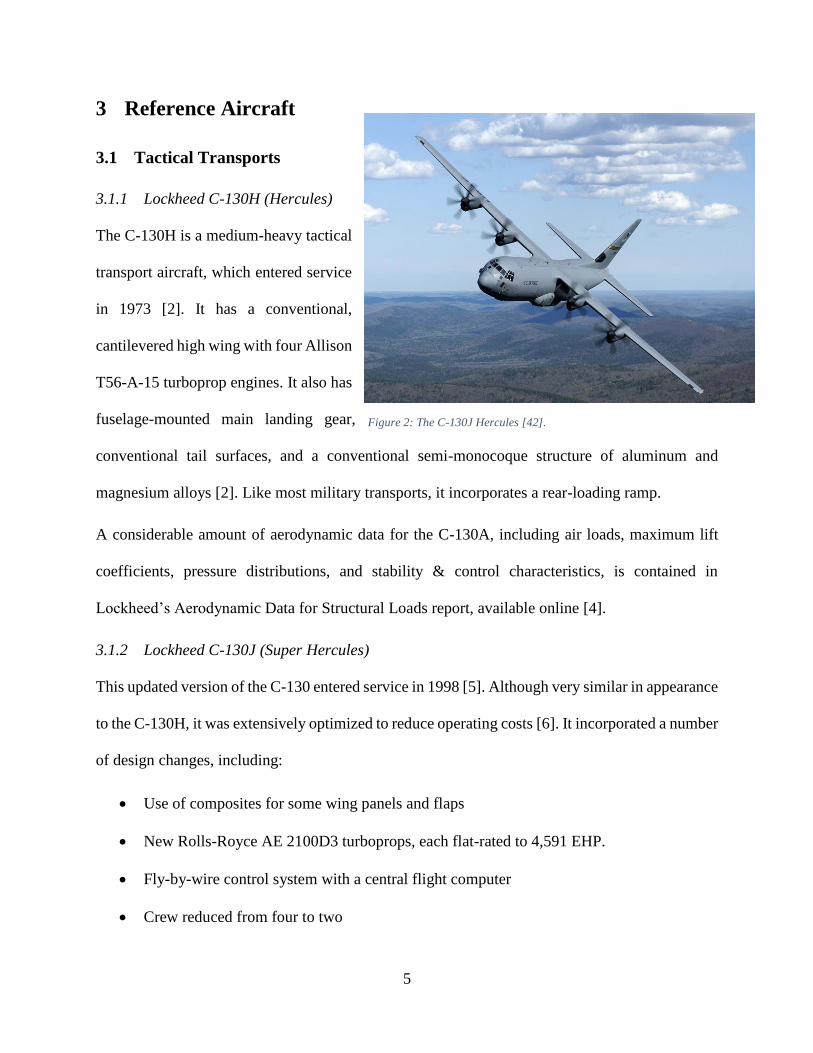
The C-130H is a medium-heavy tactical
transport aircraft, which entered service
in 1973 [2]. It has a conventional,
cantilevered high wing with four Allison
T56-A-15 turboprop engines. It also has
fuselage-mounted main landing gear,
conventional tail surfaces, and a conventional semi-monocoque structure of aluminum and
magnesium alloys [2]. Like most military transports, it incorporates a rear-loading ramp.
A considerable amount of aerodynamic data for the C-130A, including air loads, maximum lift
coefficients, pressure distributions, and stability & control characteristics, is contained in
Lockheed’s Aerodynamic Data for Structural Loads report, available online [4].
3.1.2 Lockheed C-130J (Super Hercules)
This updated version of the C-130 entered service in 1998 [5]. Although very similar in appearance
to the C-130H, it was extensively optimized to reduce operating costs [6]. It incorporated a number
of design changes, including:
Use of composites for some wing panels and flaps
New Rolls-Royce AE 2100D3 turboprops, each flat-rated to 4,591 EHP.
Fly-by-wire control system with a central flight computer
Crew reduced from four to two
Figure 2: The C-130J Hercules [42].

6
A comparison of important design characteristics from the two C-130 versions is given in Table
3. Note that the C-130J does not represent a radical improvement over the older C-130H; it is
essentially a modernization of a design dating back to 1951. This is reflected in the choice of wing
airfoils, which are identical between the C-130H and C-130J: NACA 64A-318 airfoil at wing root;
NACA 64A-412 at wing tip [2], [5]. This can further be seen by comparing key performance
parameters from Table 3, and noting that there are few significant differences.
3.1.3 Antonov An-12 (Cub)
This four-turboprop tactical transport aircraft is the Soviet equivalent of the C-130. It entered
service in 1959, with production ceasing in 1973 [2]. Key performance parameters are given in
Table 3.
3.1.4 Airbus A-400M (Atlas)
This swept-wing turboprop-powered
aircraft is by far the most modern
tactical transport in the world, having
entered service in 2013 [6]. Although
much larger and faster than any of its
counterparts, it still has comparable
takeoff and landing distances. It uses
composites extensively within the
wing and tail structures, and incorporates a fly-by-wire control system.
Figure 3: The A-400M Atlas [43].

7
Table 3: Comparison of data for existing tactical transports. Data is from [2], [5], [6], and [7].
Parameter C-130H C-130J An-12 A-400M
Service entry date 1973 1998 1959 2013
Maximum takeoff weight (lbs.) 155,000 155,000 134,480 303,135
Maximum payload weight (lbs.) 42,673 41,790 44,090 66,138
Wing area (𝑓𝑡2) 1,745 1,745 1,310 2,384
Wingspan (𝑓𝑡) 132.6 132.6 124.7 139
Cruise ESHP per engine2 (ℎ𝑝) 4,508 4,591 4,000 11,000
Cruising speed (𝑘𝑡𝑠) 300 339 ~300 402
Stalling speed (𝑘𝑡𝑠) 100 100 88 Unknown
Max rate of climb at SL (𝑓𝑡
𝑚𝑖𝑛) 1,900 2,100 1,970 4,000
Maximum wing loading (𝑙𝑏𝑠
𝑓𝑡2) 89 88.8 102.7 127.2
Maximum power loading (𝑙𝑏𝑠
𝐸𝐻𝑃) 8.6 8.44 8.41 6.89
Takeoff distance (𝑓𝑡) 3,580 3,050 2,300 3,215
Landing distance (𝑓𝑡) 1,700 1,400 1,640 2,526
Key performance parameters are given in Table 3. Note that Jane [6] contains some
inconsistencies. For example, the Design Features section on the A-400M cites a long-range
cruising speed of about Mach 0.7 at 37,000 ft (corresponding to 402 knots, the figure given in
Table 3), while the performance table gives a maximum operating speed of only 300 knots. Takeoff
and landing distances are also missing, and were instead taken from Reference [7].
2 ESHP (Equivalent Shaft Horsepower) for a turboprop engine is typically quoted as either takeoff ESHP or normal
(cruise) ESHP. The T56-A-15 engines on the C-130H have a takeoff ESHP of 4,910 ESHP [14], but takeoff ESHP
for the AE 2100D3 engines on the C-130J is not given in Jane [13]. However, [13] does state that “[the C-130J
propulsion] system provides 29% more takeoff thrust,” indicating that the takeoff ESHP of the C-130J engines is
significantly higher than that of the C-130H engines. This would explain why the C-130J has a significantly better
rate of climb and takeoff distance than the C-130H. It is also worth noting that the C-130J uses six-bladed composite
propellers, as opposed to the four-bladed propellers originally used on the C-130H.

8
3.2 Strategic Transports
The aircraft in this category are much larger than the tactical transports in the preceding section,
but they have similar max-payload ranges. For example, the C-130H has a payload capacity of
42,673 lbs. and a range of 2,046 nm [2], while the C-17 has a payload capacity of 170,900 lbs. and
a range of 2,500 nm [6].
It should be noted that the propulsion, range, runway, and payload requirements make the C-85 a
tactical, as opposed to strategic, transport. The designs in this section are primarily included as
examples of 1) more modern technology and 2) alternate design characteristics, which may be
incorporated into the C-85.
3.2.1 Boeing C-17 (Globemaster III)
This aircraft first flew in 1991; it is
currently the standard US strategic
transport. Design features include a
rear-loading ramp; a T-tail; four
turbofan engines; hinged, externally-
blown flaps; and a supercritical, swept,
high wing [6]. It is primarily relevant
because of modern design features not
present in the older C-130H, such as:
Significant use of composites (estimated 8.1% by weight, from Jane [6])
Quadruple-redundant fly-by-wire control system
It should be noted that the C-17 has a much greater carrying capacity relative to the C-130, but it
requires a longer runway. The C-17 has a takeoff distance of 7,740 ft and a landing distance of
Figure 4: The C-17 Globemaster III [44].

9
3,000 ft [6]; by contrast, the C-130J has a takeoff distance of 3,050 ft. and a landing distance of
1,400 ft [5]. Therefore, although most modern transports are strategic, tactical transports are still
relevant in situations where the runways are too short to permit strategic transports to operate.
3.2.2 Antonov An-124 (Condor)
This huge four-engine jet transport is the Ukrainian counterpart to the C-17. It entered service in
1987, and was the world’s largest production aircraft as of 2004 [5]. It has a maximum payload of
330,700 lbs., almost twice that of the C-17, while its takeoff and landing distances of 8,270 ft. and
2,955 ft. respectively are comparable to those of the C-17 [5]. It has a range of 2,430 nm with
maximum payload [6].
Interestingly, the An-124 was equipped with kneeling landing gear, which could raise or lower the
aircraft as required for loading or unloading. It takes approximately 3 minutes to lower the gear
and 6.5 minutes to raise it [5].
3.3 Flying Boxcars
A number of twin-boomed transport aircraft fall into this category. The main advantage of this
configuration is that it allows trucks to back up to the rear-loading ramp, although some examples
also had loading ramps at the front [8].
3.3.1 Fairchild C-119 (Packet)
This American twin-boomed transport aircraft first flew in 1947; it was developed from the earlier
C-82 Packet [9]. Key design features included twin piston engines, tricycle landing gear with main
wheels retracting into the engine pods, a high wing with anhedral center-section (to shorten the
landing gear), and a capacious cargo compartment with rear loading doors.

10
3.3.2 Fairchild XC-120 (Pack-Plane)
This experimental version of the C-119
was developed in the early 1950s, with
a detachable cargo-carrying fuselage.
This was purported to reduce cargo-
handling time on the ground, but only
one prototype was built and the project
was scrapped [10]. Further information
on the XC-120 was obtained from an
old edition of Jane’s All the World’s
Aircraft [11].
The XC-120 had a hatch in the floor of
the fuselage, which could be used by
the crew either to enter and exit the
plane without the cargo compartment
in place (this required a ladder), or to
access the cargo pod. A secondary
escape and servicing hatch was located
on the roof of the fuselage. The XC-120 also incorporated quadricycle landing gear folding into
the nacelles, replacing the tricycle gear of the C-119. This arrangement can be seen in Figure 6.
To attach the cargo pod, the XC-120 would first roll over the pod. Four electrical drum hoists
(mounted on the fuselage) would then be used to raise the pod to mate with four ball-and-socket
Figure 5: The XC-120 Pack-plane, with and without its cargo pod [10].
Figure 6: The XC-120 on the ground [46].

11
connections on the fuselage [12]. The final step would be to use an inflatable rubber tube to seal
off the space between the pack and the carrier aircraft.
3.4 Miscellaneous Aircraft
3.4.1 Scaled Composites White Knight Two
The world’s largest all-
composite aircraft is a good
example of aircraft designed
around an external payload.
The first White Knight Two
was built in 2007 and first
flew the next year. It serves
as a launch platform for
SpaceShipTwo, a manned suborbital space vehicle intended for commercial tourism flights. White
Knight Two and SpaceShipTwo are to be operated by Virgin Galactic, which has ordered three of
the former and five of the latter [13]. Key design features include twin fuselages, an inverted gull
wing, and quadricycle landing gear, all in order to accommodate and launch SpaceShipTwo while
in flight. White Knight Two and SpaceShipTwo are shown in Figure 7.
3.4.2 Bombardier Dash-8 Q400
The Q400, shown in Figure 8, is a modern twin-engine turboprop airliner. It entered service in
2002; more than 400 have been produced, and the aircraft is still in production [6]. It is relevant to
this work for two reasons:
Figure 7: An image of White Knight Two, with SpaceShipTwo attached [47].

12
It is powered by two Pratt &
Whitney Canada PW150A engines,
which are much more modern than
the Allison engines required by the
RFP. This is discussed further in
Section 4.4.
Its landing gear retract into the
engine nacelles, as opposed to into
fuselage sponsons like the C-130. This helps prevent the aircraft from tipping over while
on the ground, which is discussed in Section 5.4 as a significant problem for the selected
configuration.
4 Design Requirements
4.1 Design for Payload
Most of the RFP requirements (ex. range,
runway length, and takeoff distance) seem
relatively straightforward from a technical
perspective. However, the payload
requirement is unusual. The RFP specifies
a 20 ft. container as the required payload;
this container weighs 5,140 lbs. empty and
45,140 lbs. when full. Moreover, the RFP
specifies that “[the] container cannot be carried inside the airplane itself, but must be external to
Figure 9: The required container [45].
Figure 8: The Dash-8 Q400 [48].

13
the airplane [1],” and “[the] airplane must be able to fly without the container present. It should
also be possible to drop the container during flight [1].” The container is shown in Figure 9.
Three principal arrangements are envisaged for carrying such a container externally:
1. Leaving the container as-is, and loading it into the aircraft from below (the container would
remain exposed from below while in flight). The aircraft would then roll over the container
to load or unload.
2. Adding a fairing around the container, to make it more aerodynamic. The container could
then be attached and removed in a manner similar to that of the XC-120 (see Section 3.3.2).
3. Leaving the container as-is, and loading it into the aircraft from the side (the container
would remain exposed from the side while in flight). A diagram illustrating this approach
is given in Appendix C.
Approaches 1 and 2 would be greatly facilitated if the C-85 were equipped with kneeling landing
gear, capable of raising or lowering the aircraft to the level desired. It would then be possible to
drive the aircraft over the container, lower it, attach the container, raise the aircraft, and then drive
away, without any specialized ground-handling gear. Kneeling landing gear was used by both the
Antonov An-124 Condor (mentioned earlier) and the Lockheed C-5 Galaxy.
4.2 Design for Range
As shown in Section 2.1, the 1,000 nm range requirement is much too low to be useful. Therefore,
the Table 23 mission profile was used to size the C-85; a more suitable range requirement should
be defined later. In addition, provision should be made for external fuel tanks; for comparison, the
C-130H can carry two underwing fuel tanks with a combined capacity of 2,558 US gallons [6].
Provision will also be made for aerial refueling.

14
4.3 Design for STOL
The RFP requires a runway distance of less than 3,500 ft. at maximum takeoff weight; both takeoff
and landing distances must be less than this value. It can be seen from Table 3 that only the C-
130H is incapable of meeting the requirement; the C-130J, An-12, and A-400M all have takeoff
and landing distances less than 3,500 ft.
Characteristics of the high-lift systems used by current tactical transports are given in Table 4.
Note that none of the aircraft listed incorporated leading-edge slats; they all use either single- or
double-slotted Fowler flaps. It is expected that the C-85 will make use of a similar system.
Table 4: High-lift systems of current tactical transports. Information is from [14] and [6].
C-130 An-12 A-400M
Trailing-edge flaps Single-slotted
Fowler flaps
Double-slotted
Fowler flaps
Fixed-vane double-
slotted Fowler flaps
Leading-edge slats No No No
4.4 Design for Propulsion
The RFP requires that the Allison T56-A-15 engine be used [1]; it was calculated in Section 2.3
that four engines are required. This engine was used to power the C-130H. Thrust, power, and
TSFC data for this engine can be obtained from Appendix J of Fundamentals of Aircraft and
Airship Design [15]. The RFP also requires that the NP2000 propeller (an eight-bladed propeller
made by Hamilton Sundstrand) be used; 90% propeller efficiency is to be assumed [1].
The T56-A-15 is far from the best engine available. Indeed, Jane [6] cites a 15% increase in fuel
efficiency and a 29% increase in takeoff thrust for the C-130J relative to the C-130H; these
improvements are due entirely to its new propulsion system. The C-130J replaces the older T56-

15
A-15 engines with Rolls-Royce AE 2100D3 turboprops. A third engine, the Pratt & Whitney
Canada PW150A, was considered.
A summary of engine data is given in Table 5. Weights and performance metrics were obtained
from the 1996 and 2009 Aerospace Source Books [16], [17], while dimensions were obtained from
the Engines section of Jane [5].
Table 5: Comparative engine data.
Engine T56-A-15 AE 2100D3 PW150A
Manufacturer Allison Rolls-Royce Pratt & Whitney Canada
Powers Lockheed C-130H Lockheed C-130J Dash-8 Q400
Sea-level takeoff
SHP 4,591 4,591 5,071
Sea-level takeoff
SFC (𝑙𝑏𝑠
ℎ𝑟∗𝑆𝐻𝑃)
0.54 0.46 0.433
Length (ft.) 12.2 9.0 7.95
Diameter (ft.) 2.25 3.78 2.52
Weight (lbs.) 1,848 1,644 1,583
Table 5 shows that the PW150A outperforms both the T56-A-15 and the AE 2100D3 in terms of
sea-level takeoff SHP, while being both smaller and lighter. It also has significantly lower fuel
consumption than either of the other two engines. An upgraded version of the PW150A (the PW-
150C) is being considered to power the XAC MA700 notional Chinese twin-turboprop airliner [6].
The T56-A-15 will be used to power the C-85 as per the RFP requirements; however, the PW150C
will be considered as an upgrade, especially for a civilian variant.
4.5 Design for Advanced Technology
The C-85 design should make use of the latest advanced technologies, in order to outperform
existing military transports. Various technologies and their impacts are discussed in this section.

16
4.5.1 Natural Laminar Flow
Natural laminar flow involves shaping an aircraft wing or fuselage to achieve long runs of laminar
flow, without any active control mechanisms. This technology is under consideration for the C-85
in part because the C-130 (both H and J) used NACA 6-series airfoils: NACA 64A-318 at wing
root; NACA 64A-412 at wingtip [2], [6]. These airfoils were designed explicitly for long runs of
laminar flow. Wind-tunnel data for the 64A-412 airfoil can be found in an old NACA report [18].
It is worth noting that the data in [18] only includes data for Reynolds numbers of 3𝑒6, 6𝑒6,
and 9𝑒6, while the C-85 has an estimated cruise Reynolds number of 22𝑒6. Not only does this
high Reynolds number invalidate the NACA data, it also means that laminar flow will be much
harder to maintain. Furthermore, any mud, dirt, or insects on the wing leading edge will ruin
laminar flow, and the presence of propellers will make obtaining laminar flow even more difficult.
However, the Lockheed engineers still chose laminar-flow airfoils, indicating that at least some
laminar flow is possible. Therefore, as a first-order approximation, 5% laminar flow will be
assumed for any wing sections in the propwash (laminar-flow is possible behind propellers,
according to Raymer [19]); wing sections outside the propwash will be assumed to have 15%
laminar flow. The 6-series foils can be used as a starting point for airfoil selection.
4.5.2 Advanced Composites
Composite materials are increasingly being used in aerospace applications due to their high
strength, high stiffness, and low weight. However, composites can in many cases be more
expensive and more difficult to manufacture and repair than metals. Despite these drawbacks, most
modern transport aircraft use composites extensively. For example, the C-130J (unlike the all-
metal C-130H) uses carbon-fiber flaps and graphite-epoxy trailing-edge wing panels [6]. The C-
17 is 8.1% composites by mass (not including the redesigned all-composites horizontal tail), while
17
the A-400M uses composites for the horizontal tail box, elevator, vertical fin, rudder, and wing
(except ribs) [6]. The C-85 makes even greater use of composites (see Section 9.2.3).
4.5.3 Active Load Alleviation
Active load alleviation involves automatically deflecting the control surfaces as loads on the
aircraft are increased. The aim is to alter the lift distribution to concentrate lift inboard, reducing
wing bending moments. If applied to an existing aircraft, load alleviation will increase the useful
load; if applied to a new aircraft, load alleviation can be used to save wing structural weight.
There are two forms of active load alleviation commonly discussed in the literature: maneuver
load alleviation (or MLA, in which the controls are deflected in response to high-g maneuvers),
and gust load alleviation (or GLA, in which the controls are deflected in response to gusts). Flutter
load alleviation is also occasionally discussed.
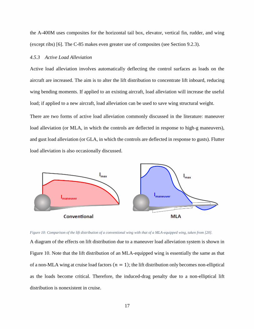
Figure 10: Comparison of the lift distribution of a conventional wing with that of a MLA-equipped wing, taken from [20].
A diagram of the effects on lift distribution due to a maneuver load alleviation system is shown in
Figure 10. Note that the lift distribution of an MLA-equipped wing is essentially the same as that
of a non-MLA wing at cruise load factors (𝑛 = 1); the lift distribution only becomes non-elliptical
as the loads become critical. Therefore, the induced-drag penalty due to a non-elliptical lift
distribution is nonexistent in cruise.

18
Like many ideas in aerospace, active load alleviation is not new. The concept of deflecting control
surfaces to reduce wing loads was patented in 1949 by the Douglas Aircraft Corporation, while
the first comprehensive design study on maneuver load alleviation known to this author was
published in 1971 by Roland White of the Aerophysics Research Corporation [21]. By applying a
MLA system incorporating both ailerons and flaps to a large transport aircraft design, the former
Boeing design specialist was able to demonstrate that a 10% wingspan increase was possible
without increasing wing weight.
The first aircraft to fly with a load alleviation system was an upgraded version of the Lockheed L-
1011 TriStar widebody airliner (the L-1011-500), in 1979 [22]. At the time, Lockheed was seeking
to extend the TriStar wingspan by 9 feet. A maneuver load alleviation system was required to
ensure that the wingspan extensions did not require redesign of the entire wing to handle the
resulting increased loads. The system incorporated accelerometers in three locations: the left
wingtip, right wingtip, and the fuselage. A dynamic-pressure sensor was also required. The system
only utilized the outboard ailerons; flaps were not used. Also, only MLA was implemented; GLA
was studied, but ultimately rejected due to marginal benefits [22]. The upgraded TriStar was
certified in 1980, and entered service with Pan Am the same year. Lockheed also instituted a
program to retrofit all existing L-1011-500s with the new system [23].
Research into active load alleviation systems is ongoing. NASA has conducted a number of
theoretical and experimental studies of both MLA and GLA systems [24], [25], [26]. More
recently, MLA and GLA were featured in a number of airliner multidisciplinary optimization
studies at Stanford [20], [27]. The Airbus A320 and A330 are known to incorporate maneuver load
alleviation systems [20], while unconfirmed rumors suggest that the Airbus A380 and Boeing 787
also have MLA systems. The B-2 Spirit has a gust load alleviation system [28].

19
The chief obstacle to more widespread use of MLA and GLA is the required flap actuation speed.
White [21] showed that using ailerons and flaps together results in a significantly larger MLA
benefit than use of ailerons alone; this requires the flaps to be able to quickly respond to commands
from a central flight computer. However, most large modern transport aircraft incorporate slotted
Fowler flaps (see Section 4.3), which take some time (~10 s) to deploy. There are a number of
ways this problem can be solved with the C-85:
1. By using a plain hinged flap. This will result in a lower maximum lift coefficient than would
be obtainable with a single- or double-slotted Fowler flap, but its faster actuation speed would
allow the full benefit of MLA and GLA to be realized.
2. By using a single- or double-slotted Fowler flap, and only applying MLA and GLA using the
ailerons. This method would entail considerably lower technical risk (this is what was done
with the TriStar), and a high maximum lift coefficient could be obtained. However, the full
potential of MLA and GLA cannot be realized in this manner.
As a first-order estimate of the effects of a load alleviation system, the 12.2% wing-weight bonus
from Table 1 in Reference [21] should be assumed if Option 1 is selected. An 8.2% bonus (also
from [21]) should be assumed if Option 2 is selected.
The C-85 incorporates Option 2 (slotted Fowler flaps, MLA/GLA on the ailerons only; 8.1% wing-
weight bonus). A trade study should be performed later to address the relative merit of the two
options.
4.6 Design for Alternative Missions
The C-130 was famous for the variety of roles in which it served (and continues to serve)
throughout its career. Several alternative roles are contemplated for the C-85; these include:
20
Civilian Transport: a civilian variant of the C-130 (known as the L-100) exists. It is
primarily used to carry freight, but can also be employed for passengers (as in Indonesia’s
transmigration program), firefighting, surveillance, casualty evacuation, and humanitarian
relief [2], [6].
Tanker: The US Marine Corps uses KC-130 aircraft as probe-and-drogue tankers, with
extra fuel tanks in the cargo bay and on underwing pylons [2].
Gunship: a number of C-130 variants were converted to AC-130s, equipped with a variety
of side-firing weapons including 30mm and 40mm guns, Hellfire and Griffin missiles, and
105mm howitzers [14], [6]. The C-119 also served as a gunship, as the AC-119. If the C-
85 is to serve in this role, any weapons must have a clear field of fire (i.e. not obstructed
by the wing or engines).
Paratroop Transport: provision should be made for accommodation of paratroops inside a
suitably modified cargo container. This may require the paratroops to have access to the
cockpit. In the case of the XC-120, this was accomplished with a hatch in the ceiling of the
cargo pod, corresponding to a hatch in the cockpit floor [11].
4.7 Design for Export
The C-130J is one of the world’s widely exported military aircraft. At least 55 nations ordered C-
130H models as of 1984; Lockheed had received a total of 1,729 Hercules orders by that year, of
which 1,702 had been delivered. 558 of the orders were placed by militaries other than the United
States, while 97 orders were for commercial versions [2]. Sales of the C-130J totaled 461 as of
2014, with 127 orders coming from 15 countries outside the United States [6].
It is worth noting that there is no modern competitor aircraft in the same class as the C-130J. The
A-400M is the only other modern tactical transport, but it is much larger and has a significantly
21
higher payload capacity (see Table 3). Also, the A-400M program suffered from significant cost
overruns, estimated at €1.4 billion out of a total €5.5 billion in 2006 [6]. The unit price of an Atlas
was quoted as €100 million in 2006 (about $150 million US dollars in 2015), while the unit price
of a Super Hercules was quoted as approximately $67.5 million US in 2002 (about $89 million US
in 2015). It is therefore desirable for the C-85 to have a unit price less than $89 million US, as well
as a lower operating cost. If this can be achieved, the C-85 would be a very competitive candidate
for export.
The desirability of a low operating cost provides additional impetus to use PW150C engines (see
Section 4.4), in order to gain the commensurate fuel savings.
5 Aircraft Configurations
Four main configuration options have been identified. The first is a modified C-130H or C-130J,
while the other three depend on the cargo-container storage method: internally, with the container
extracted from below; externally, with fairings fitted in front and behind the container; and
internally, with the cargo container extracted from the side. The relative merits of each are
discussed in this section.
5.1 Modified C-130H or C-130J
The C-130H and C-130J already meet most of the design requirements. Exceptions include the
3,500 ft. runway requirement, the 45,140 lbs. payload requirement, the engine requirement, and
the external-payload requirement. The runway requirement is met by the C-130J but not the C-
130H (see Table 3); the two aircraft have maximum payloads of 42,673 and 41,790 lbs.
respectively (Table 3). Also, both aircraft have a cargo hold with dimensions of 40 ft. x 10.25 ft.
x 9 ft. [6], which is sufficient to carry the container.
22
The main advantage of this configuration is its low technical risk, as the aircraft already exists.
Negotiations with the customer could be conducted to lower the payload requirement to what the
C-130H and -J can already carry. Alternatively, an active load alleviation system could be fitted
to the C-130J ailerons (as was done with the TriStar) to raise the maximum payload to the required
45,140 lbs. This would be difficult (but not impossible) to do with the C-130H due to its lack of a
fly-by-wire control system. The external-payload requirement would also have to be negotiated,
as it cannot be met without a clean-sheet design. Finally, the C-130H uses the required engines,
but the C-130J does not.
There are two main problems with this idea. The first problem is that, as detailed above, neither
model is capable of meeting all of the design requirements. The second problem is that the C-130
is a very old design; the initial design specification was released in 1951 [14]. Significant
improvements should be possible with more modern technology. This is especially important due
to the desirability of civilian and export variants (see Sections 4.6 and 4.7).
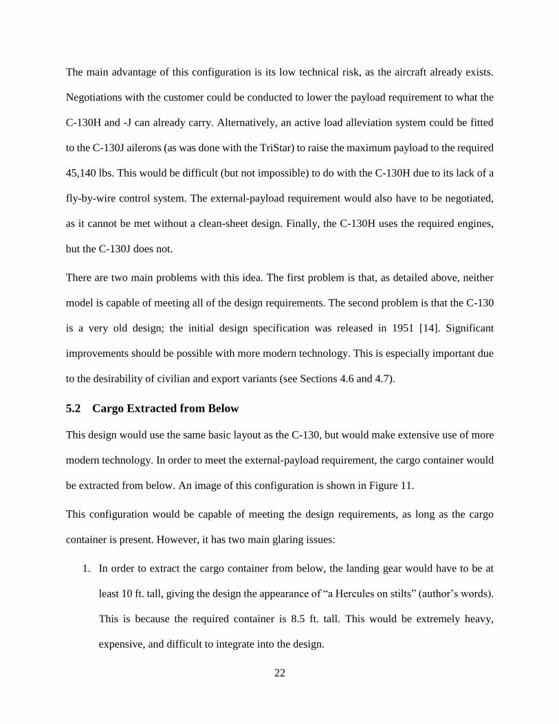
5.2 Cargo Extracted from Below
This design would use the same basic layout as the C-130, but would make extensive use of more
modern technology. In order to meet the external-payload requirement, the cargo container would
be extracted from below. An image of this configuration is shown in Figure 11.
This configuration would be capable of meeting the design requirements, as long as the cargo
container is present. However, it has two main glaring issues:
1. In order to extract the cargo container from below, the landing gear would have to be at
least 10 ft. tall, giving the design the appearance of “a Hercules on stilts” (author’s words).
This is because the required container is 8.5 ft. tall. This would be extremely heavy,
expensive, and difficult to integrate into the design.

23
2. The aerodynamics of the cargo hold with container removed (especially at higher angles
of attack) are extremely complex. To design for this, a plate should be included above the
cargo container, such that it lowers to cover the hole.
Figure 11: Sketch of a hypothetical configuration with cargo extracted from below.
5.3 External Cargo Container with Fairing
This configuration was heavily inspired by White Knight Two (discussed in Section 3.4.1). A
removable fairing is fitted to the cargo container, which is then attached to the fuselage by a winch
system as with the XC-120. Integrating the winch system into the fuselage allows for operation
from unprepared airstrips, without ground-handling equipment. The container is situated at least 6
feet off the ground, which allows flatbed trucks to back up to load or unload cargo (standard flatbed
trucks have trailer heights less than 4.9 ft. [29]). Inverted gull wings are used to keep the landing
gear as short as possible. An image of this configuration is shown in Figure 12.
This configuration uses an H-tail, in order to facilitate dropping the cargo pod in flight without
risk of collision with the tail. Quadricycle landing gear (not shown) is also used. The fairings would
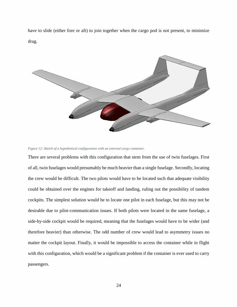
24
have to slide (either fore or aft) to join together when the cargo pod is not present, to minimize
drag.
Figure 12: Sketch of a hypothetical configuration with an external cargo container.
There are several problems with this configuration that stem from the use of twin fuselages. First
of all, twin fuselages would presumably be much heavier than a single fuselage. Secondly, locating
the crew would be difficult. The two pilots would have to be located such that adequate visibility
could be obtained over the engines for takeoff and landing, ruling out the possibility of tandem
cockpits. The simplest solution would be to locate one pilot in each fuselage, but this may not be
desirable due to pilot-communication issues. If both pilots were located in the same fuselage, a
side-by-side cockpit would be required, meaning that the fuselages would have to be wider (and
therefore heavier) than otherwise. The odd number of crew would lead to asymmetry issues no
matter the cockpit layout. Finally, it would be impossible to access the container while in flight
with this configuration, which would be a significant problem if the container is ever used to carry
passengers.
25
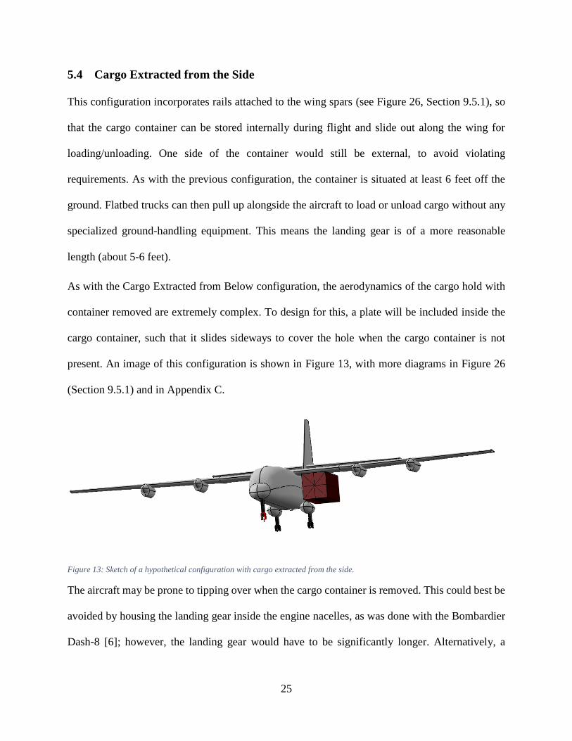
5.4 Cargo Extracted from the Side
This configuration incorporates rails attached to the wing spars (see Figure 26, Section 9.5.1), so
that the cargo container can be stored internally during flight and slide out along the wing for
loading/unloading. One side of the container would still be external, to avoid violating
requirements. As with the previous configuration, the container is situated at least 6 feet off the
ground. Flatbed trucks can then pull up alongside the aircraft to load or unload cargo without any
specialized ground-handling equipment. This means the landing gear is of a more reasonable
length (about 5-6 feet).
As with the Cargo Extracted from Below configuration, the aerodynamics of the cargo hold with
container removed are extremely complex. To design for this, a plate will be included inside the
cargo container, such that it slides sideways to cover the hole when the cargo container is not
present. An image of this configuration is shown in Figure 13, with more diagrams in Figure 26
(Section 9.5.1) and in Appendix C.
Figure 13: Sketch of a hypothetical configuration with cargo extracted from the side.
The aircraft may be prone to tipping over when the cargo container is removed. This could best be
avoided by housing the landing gear inside the engine nacelles, as was done with the Bombardier
Dash-8 [6]; however, the landing gear would have to be significantly longer. Alternatively, a

26
folding strut could be included inside the inner left engine pod, which would be lowered when
loading or unloading cargo. This would also provide bending-moment relief to the wing spars. A
more radical solution is to switch to bicycle landing gear, with outrigger wheels (see Figure 11.2
in [19] for a sketch). Finally, folding supports could be attached to the fuselage, as is currently
done with fire trucks to prevent them from tipping over when the ladder is extended. Other
problems with this configuration include:
Large additional bending moments will be imposed on the wing spar during
loading/unloading.
There is a risk that the cargo container will hit either the tailplane or the landing-gear
fairings if the container is dropped in flight. The gear fairings can be avoided by dropping
the container while the aircraft is at a bank angle; a T-tail can be used to overcome the
resultant risk of collision with the tailplane.
In order to drop the container in flight, it must be deployed out along the wing. This will
create very large yawing and rolling moments. The rudder and ailerons may have to be
oversized to account for this; alternatively, a system could be designed such that the
container is “shoved” out the cargo door quickly. The rails may also need explosive bolts,
in order to drop the container in case the rails jam in flight.
This configuration was selected for continued analysis. This is because it is the simplest
configuration to design that can meet all of the requirements. The landing-gear length appears
reasonable, while the single fuselage saves weight and design complexity. Finally, the four
principal problems discussed above appear to be solvable.

27
6 Analysis Methods
A significant amount of MATLAB code was written to perform the analyses presented throughout
the rest of this report. The propulsive, aerodynamic, performance, and mission analysis codes were
particularly involved, and as such are detailed in this section.
6.1 Propulsive Analysis
A function called T56_A_15_thrust was written in MATLAB to generate 𝑇(𝑉, ℎ) and
𝑇𝑆𝐹𝐶(𝑉, ℎ) curves (net thrust and thrust-specific fuel consumption vs. speed and altitude) for the
Allison T56-A-15 engine. The function incorporates power, thrust, and ESFC (equivalent specific
fuel consumption) data for the T56-A-15 engine, from Fundamentals of Aircraft and Airship
Design [15]. This data is given for both takeoff and normal (cruise) conditions.
The function first obtains the propeller thrust. This was done by fitting a cubic spline to the power
data from [15], compensating for installed-engine effects. As required by the RFP, a propeller
efficiency of 90% was assumed; scrubbing drag, cooling drag, and miscellaneous drag were
estimated using Equations 13.21, 13.22, and 13.23 from Raymer respectively [19]. The resulting
power value was converted to thrust by dividing through by velocity. Note that a singularity results
at zero velocity; to account for this, if the velocity corresponded to a Mach number less than 0.1,
the velocity at M0.1 was used instead of the actual velocity. A similar method was used by Raymer
to obtain the uninstalled-engine data for the hypothetical turboprop engine included in Appendix
E of [19].
The function next obtains the jet thrust. As with the propeller thrust, a cubic spline was fitted to
the thrust data from [15]. Two installed-engine effects were incorporated: inlet pressure recovery
and bleed extraction, which were estimated using Equations 13.6 and 13.8 from Raymer
respectively [19].

28
The final step was to obtain the thrust-specific fuel consumption data. This was done by fitting a
cubic spline to the ESFC data from [15], multiplying by total (uninstalled) power to get fuel burn
per hour, then dividing by total (installed) thrust to get installed TSFC. Sample thrust and TSFC
results (for one engine only) are given in Figure 14.
Figure 14: Installed net thrust and TSFC data for the Allison T56-A-15 engine.
6.2 Aerodynamic Analysis
The drag polar of an aircraft can be estimated as follows:
𝐶𝐷 = 𝐶𝐷0+ 𝐾(𝐶𝐿 − 𝐶𝐿𝑚𝑖𝑛
)2 (3)
29
𝐶𝐷 is the total drag coefficient, 𝐾 is the lift-induced drag factor, 𝐶𝐿 is the lift coefficient, and 𝐶𝐿𝑚𝑖𝑛
is the lift coefficient for minimum drag. 𝐶𝐿𝑚𝑖𝑛 was estimated as 0.255 (the same value as the C-
130, from the Aerodynamics report [4]) in this work3.
A function called aero_parameters was written in MATLAB to estimate 𝐶𝐷0 and 𝐾, for
varying flight conditions. The function has four inputs: a structure containing the aircraft geometric
data, two arrays containing the velocities and altitudes respectively (the function is vectorized with
respect to these arrays; they must both be the same size), and a condition string. The condition
string has three configuration settings:
Cruise (returns the coefficients for the clean airplane)
Takeoff (adds landing-gear drag and flap drag at the takeoff setting)
Landing (adds landing-gear drag, flap drag at the landing setting, spoiler drag, and
windmilling-engine drag)
Zero-lift drag was obtained using a wetted-area method, from Raymer [19]. In this method, the
first step is to estimate the drag of the various major aircraft components. This was done using an
equivalent-flat-plate technique (including both Reynolds and Mach effects), with correction
factors to account for pressure drag and interference drag. Drag estimates of six components were
estimated in this manner: the wing, fuselage, tailplane, vertical fin, landing-gear sponsons, and
engine nacelles. 10% laminar flow was assumed for the wing4, tail, and vertical fin; the other
components were fully turbulent.
3 The C-85-1 wing uses the NACA 64A-315 airfoil, similar to the NACA 64A-318 and NACA 64A-412 airfoils used
for the C-130 wing (see Section 0). It is therefore assumed that the 𝐶𝐿𝑚𝑖𝑛 value of 0.255 can be achieved with proper
selection of tail airfoils, incidences, and twist. More information on this choice is given in Section 10.4. 4 Recall from Section 4.5.1 that 5% and 15% laminar flow was assumed for wing sections in and out of the propwash
respectively. The value of 10% is an average of the two, and was used to simplify the analysis.

30
The next step was to estimate the additional drag due to miscellaneous sources. Five sources were
included: landing-gear drag, fuselage-upsweep drag, flap drag, spoiler drag, and windmilling-
engine drag. Landing-gear drag and spoiler drag were estimated using Table 12.6, while fuselage-
upsweep drag, flap drag, and windmilling-engine drag were estimated using Equations 12.36,
12.61, and 12.39 respectively (all from Raymer [19]). The final step is an allowance for leakage
& protuberance drag, conservatively estimated as 7% of the total.
Induced drag was obtained using an Oswald-efficiency method:
𝐾 =1
𝜋𝑒𝐴𝑅 (4)
𝐴𝑅 is the wing aspect ratio, and 𝑒 is the Oswald efficiency. The Oswald efficiency was obtained
using the Equation (5), taken from Grant [30]:
𝑒 =
1
1𝑒𝑖𝑛𝑣𝑖𝑠𝑐𝑖𝑑
+ 𝜋𝐴𝑅𝑘𝐶𝐷0
(5)
𝑒𝑖𝑛𝑣𝑖𝑠𝑐𝑖𝑑 is the inviscid Oswald efficiency, 𝐶𝐷0 is the zero-lift drag coefficient, while 𝑘 was
estimated as 0.38.
6.3 Performance Analysis
To perform performance analysis, a code called performance_maindriver was written in
MATLAB. This program solves for five of the key performance metrics required by the RFP:
maximum speed, maximum rate of climb, service ceiling, takeoff distance, and landing distance.
performance_maindriver calls a number of other functions, all of which directly use the
propulsive and aerodynamic functions where necessary.
31
6.3.1 Maximum Speed
The RFP requires a cruising speed of at least 250 knots at 23,000 ft.; the maximum speed must be
greater than this value. To solve for the maximum speed, performance_maindriver calls
a function called maximum_speed, which uses MATLAB’s fsolve nonlinear solver function
to zero the difference between aerodynamic drag and available thrust (from
T56_A_15_thrust).
6.3.2 Maximum Lift Coefficient and Stalling Speed
The methods used to estimate maximum lift coefficient varied between aircraft versions, and as
such are detailed in their own sections. However, an aircraft with wing-mounted engine-driven
propellers will benefit from an increased lift slope (𝐶𝐿𝛼) and increased maximum lift coefficient
(𝐶𝐿𝑚𝑎𝑥) while the engines are running. This is most relevant at takeoff, when maximum engine
thrust is required.
Lockheed’s C-130 Aerodynamic Data for Structural Loads report [4] includes two charts that
document this effect. The charts, included on pages 30 and 31 of the report, plot lift coefficient vs.
angle of attack for different values of 𝐶∆ (power coefficient5). It can be seen that both 𝐶𝐿𝛼 and
𝐶𝐿𝑚𝑎𝑥 are significantly higher when the engines are on. Equation (6), estimated using data from
these charts, was then implemented in a function called CLmax_increment:
∆𝐶𝐿𝑚𝑎𝑥= 0.3 + 2𝐶∆ (6)
5 It is more typical to use a different definition of power coefficient: 𝐶𝑝 =
𝑃
𝜌𝑛3𝐷5, where P is the power, 𝜌 is the air
density, 𝑛 is the propeller rotational velocity in rev/s, and 𝐷 is the propeller diameter [15]. Thrust coefficient
(𝐶𝑇 =𝑇
𝜌𝑛2𝐷4) is also used in the literature. However, the C-130 Aerodynamics report uses the following definition of
power coefficient: 𝐶∆ =𝑇
𝑞𝑆=
𝑇1
2𝜌𝑉2𝑆
. Since data was obtained from this report, the 𝐶∆ definition was used here.

32
∆𝐶𝐿𝑚𝑎𝑥 is the increment in maximum lift due to the engines. Equation (6) can return inordinately
high 𝐶𝐿𝑚𝑎𝑥 estimates at low speeds, so ∆𝐶𝐿𝑚𝑎𝑥
was capped at 2 (i.e. CLmax_increment cannot
return a value of ∆𝐶𝐿𝑚𝑎𝑥 greater than 2).
Engine-on maximum lift coefficient is a function of airspeed through the 𝐶∆ term in Equation (6).
For this reason, stalling speed and maximum lift coefficient are dependent on each other, and must
be solved for simultaneously. A function called stalling_speed was written in MATLAB for
this purpose. stalling_speed uses MATLAB’s fzero function, along with
CLmax_increment, to iteratively solve for the airspeed at which the lift coefficient is equal
to the maximum. The function returns both stalling speed and maximum lift coefficient, and is
used throughout the performance estimates.
6.3.3 Maximum Rate of Climb
The RFP requires that the maximum rate of climb be greater than 1,500 fpm at 10,000 feet and
maximum takeoff weight (MTOW). To solve for the maximum rate of climb, a function called
max_rate_of_climb was written in MATLAB. This function uses MATLAB’s fmincon
nonlinear minimization function to maximize the aircraft rate of climb (given altitude), using
airspeed as an optimization variable. A constraint was included to ensure that the lift coefficient is
less than the maximum. Rate of climb (given airspeed and altitude) was computed using Equation
(17.39) from Raymer [19].
6.3.4 Service Ceiling
The RFP requires that the service ceiling be greater than 33,000 feet with the container empty, but
present. To solve for the service ceiling, a function called service_ceiling was written in
MATLAB. This function uses MATLAB’s fmincon function, with velocity and altitude as

33
design variables. The objective function is altitude, and two constraints are implemented: a rate of
climb of 100 fpm, and a stalling-speed constraint.
6.3.5 Takeoff Distance
The RFP imposes a takeoff-distance requirement of 3,500 ft. Since the C-85 is a military aircraft,
reference was made to Military Standard MIL-C5011A, which requires takeoff distance over a 50-
ft obstacle [19]. A function called takeoff_distance was written in MATLAB for this
purpose; the function returns stalling speed, maximum lift coefficient, and climb angle as well as
the takeoff distance. Rolling-coefficient, takeoff-speed, and climb-speed requirements in MIL-
C5011A were all adhered to.
All takeoff-distance calculations (except for stalling speed and maximum lift coefficient, which
were computed using stalling_speed) used methods from Raymer [19]. Ground roll was
computed by numerically integrating Equations (17.100) and (17.101) from Raymer, with an
adjustment for the 𝐶𝐿𝑚𝑖𝑛 term in Equation (3) in this report. Rotation was assumed to take 3s at
takeoff speed, while transition and climb distances were computed using Equations (17.110) and
(17.112) from Raymer respectively. A detailed breakdown for the C-85-3 (the final aircraft
version) is given in Table 26 (Appendix F).
6.3.6 Landing Distance
The RFP imposes a landing requirement of 3,500 ft. As with takeoff distance, reference was made
to Military Standard MIL-C5011A, which requires landing distance over a 50-ft obstacle [19]. A
function called landing_distance was written in MATLAB for this purpose; it returns
stalling speed, maximum lift coefficient, and approach angle as well as the takeoff distance.
Rolling-coefficient, approach-speed, and touchdown-speed requirements in MIL-C5011A were all
adhered to.
34
As landing is essentially takeoff in reverse [19], landing_distance uses most of the same
equations as takeoff_distance. However, there are a few key differences. First of all, since
the engines are not used for approach, there is no benefit to 𝐶𝐿𝑚𝑎𝑥. Secondly, reversible-pitch
propellers are used for the ground roll, which are assumed to provide 50% of the normal engine
thrust in reverse during the ground roll6. Finally, landing_distance incorporates two
different landing techniques: normal and max. If normal is selected, the approach angle is limited
to 3° as per transport-aircraft requirements [19], and the delay between touchdown and application
of brakes and reversible propellers is assumed to be 2s. If max technique is used, the approach
angle is the maximum possible (about 12°), and the delay is reduced to 1s. A detailed breakdown
for the C-85-3 (the final aircraft version) is given in Table 27 (Appendix F) 7.
6.4 Mission-Profile Analysis
To determine whether the C-85 is capable of flying the mission profile in Table 23, a program
called mission_maindriver was written in MATLAB. This function solves for the fuel burn
for each mission segment. For simplicity, the same weight fractions given in Table 23 for
warmup/takeoff, climb, descent, and reserves were used. The Breguet range equation is used to
compute the fuel burn in cruise, with L/D ratio obtained using aero_parameters and TSFC
from T56_A_15_thrust.
It is assumed that in some cases, the C-85 will have to fly out with a full payload (such as during
a medical evacuation, or an aborted mission). For this purpose, mission_maindriver solves
for the fuel burn under two different conditions: one with a payload drop, and one without.
6 Raymer recommends using 60% for turboprops [19], but T56_A_15_thrust cannot separate jet and propeller
thrust. Moreover, thrust reversers cannot be used to reverse the jet thrust for landing for regulatory reasons [19]. 7 Ground effect was not included for either takeoff or landing distances.

35
7 C-85-1 Analysis
7.1 Weight & Balance
A preliminary layout of the C-85 (the Dash-One) was created in Vehicle Sketch Pad (VSP). Weight
estimates were also obtained, using methods from Chapter 15 of Raymer [19]. The layout is shown
in Figure 15, while weight summary and dimensions are given in Table 6 and Table 7 respectively.
Component weights are given in Appendix B.
Table 6 contains a parameter called the “design weight margin” which is the percentage by which
the design takeoff weight is greater than the calculated takeoff weight. All performance
calculations and component weight estimates use the design takeoff weight; this provides
insurance against weight growth later in the design process. A design weight margin of 3-10% is
typical for conceptual design [19].
Table 6: C-85-1 weight summary. The design takeoff weight is 175,800 lbs, close to the C-130J value of 175,000 lbs [6].
Component Weight (lbs)
Empty weight 76,991.2
Fuel weight 40,783
Crew weight 600
Payload weight 45,140
Gross takeoff weight (calculated) 163,514.5
Gross takeoff weight (design) 175,800
Design weight margin 7.51%
Note from Table 7 that the tailplane volume coefficient is 1.6, much higher than Raymer’s
recommended value of 1.0 [19]. This was required because the unusual payload means that the C-
85 has a center of gravity that is relatively far back, as compared to the C-130. A large horizontal
tail was required to ensure a reasonably large static margin.

36
Table 7: C-85-1 dimensions.
Wing Wing area 1789 ft2
Wing aspect ratio 11.1
Wingspan 141 ft
Taper ratio 0.45
Aileron area 193.2 ft2
Flap area 166.3 ft2
Spoiler area 133.1 ft2
Fuselage Length 100 ft
Width 12 ft
Height 11 ft
Tailplane Tail moment arm 50.4 ft
Tailplane aspect ratio 5
Tailplane taper ratio 0.5
Volume coefficient 1.6
Tailplane area 772.2 ft2
Tailplane span 62.1 ft
Elevator area 185.3 ft2
Vertical Fin Vertical fin aspect ratio 1.4
Volume coefficient 0.08
Vertical fin area 400.0 ft2
Vertical tail height 20.4 ft
Rudder area 108.8 ft2
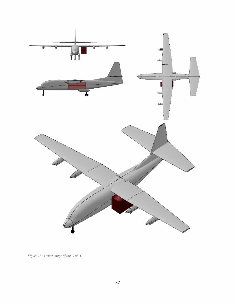
37
Figure 15: 4-view image of the C-85-1.

38
7.2 Aerodynamic Analysis
The inviscid Oswald efficiency of the C-85-1 was estimated at 0.8. Figure 16 is a comparative
drag polar, showing the C-85-1 and C-130. C-130 aerodynamic parameters were obtained from
the Aerodynamic Data report [4]. The drag polars of the two aircraft are comparable, validating
the analysis technique.
Figure 16: Drag polars for the C-85-1 and C-130.
7.3 Performance Analysis
A performance summary for the C-85-1 is given in Table 8. All requirements are met.
Table 8: Summary of performance requirements and results.
RFP Requirement Actual Value
Maximum speed at 23,000 ft. and
MTOW (knots)
>250 332.7 Requirement met
Maximum rate of climb at 10,000 ft.
and MTOW (fpm)
>1,500 1,648 Requirement met
Service ceiling (container empty, but
present; ft.)
>33,000 35,549 Requirement met
Takeoff distance (ft.) <3,500 2,097 Requirement met
Landing distance (ft.) <3,500 2,846 Requirement met
39
7.3.1 Maximum Speed
The C-85-1 has a maximum speed of 332.7 knots at 23,000 ft., easily meeting the 250-knot
requirement8. For comparison, the C-130J has a maximum speed of 355 knots at 25,000 ft. [13].
7.3.2 Maximum Lift Coefficient
The C-85-1 is similar to the C-130 in many respects (dimensions, powerplant, airfoils, and high-
lift system9). Therefore, as a first approximation, the C-85 performance analysis used the same
engine-off maximum lift coefficients as the C-130, obtained from the Aerodynamics report [4]:
𝐶𝐿𝑚𝑎𝑥 (𝑐𝑟𝑢𝑖𝑠𝑒) = 1.6
𝐶𝐿𝑚𝑎𝑥 (𝑡𝑎𝑘𝑒𝑜𝑓𝑓) = 2.0
𝐶𝐿𝑚𝑎𝑥 (𝑙𝑎𝑛𝑑𝑖𝑛𝑔) = 2.6
These coefficients were adjusted for engine-on effects as discussed in Section 6.3.2.
7.3.3 Maximum Rate of Climb
Table 8 shows that the C-85-1 has a maximum rate of climb of 1,648 fpm at 10,000 feet, which
meets the 1,500 fpm requirement. However, this could only be achieved with engines at the takeoff
setting. With engines at the normal setting, the maximum rate of climb drops to 1,368 fpm, which
does not meet requirements.
7.3.4 Service Ceiling
The C-85-1 has a service ceiling of 35,549 ft., which meets the 33,000 ft. requirement. This was
achieved with engines at the normal setting; takeoff power was not required.
8 This was computed with engines at the normal setting (as opposed to the takeoff setting, which would have yielded
an even higher maximum speed if used). 9 The C-85-1, like the C-130, uses a single-slotted Fowler flap system.
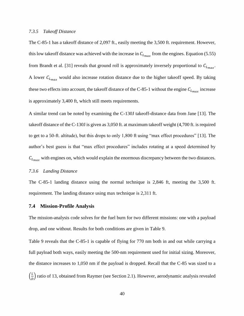
40
7.3.5 Takeoff Distance
The C-85-1 has a takeoff distance of 2,097 ft., easily meeting the 3,500 ft. requirement. However,
this low takeoff distance was achieved with the increase in 𝐶𝐿𝑚𝑎𝑥 from the engines. Equation (5.55)
from Brandt et al. [31] reveals that ground roll is approximately inversely proportional to 𝐶𝐿𝑚𝑎𝑥.
A lower 𝐶𝐿𝑚𝑎𝑥 would also increase rotation distance due to the higher takeoff speed. By taking
these two effects into account, the takeoff distance of the C-85-1 without the engine 𝐶𝐿𝑚𝑎𝑥 increase
is approximately 3,400 ft, which still meets requirements.
A similar trend can be noted by examining the C-130J takeoff-distance data from Jane [13]. The
takeoff distance of the C-130J is given as 3,050 ft. at maximum takeoff weight (4,700 ft. is required
to get to a 50-ft. altitude), but this drops to only 1,800 ft using “max effect procedures” [13]. The
author’s best guess is that “max effect procedures” includes rotating at a speed determined by
𝐶𝐿𝑚𝑎𝑥 with engines on, which would explain the enormous discrepancy between the two distances.
7.3.6 Landing Distance
The C-85-1 landing distance using the normal technique is 2,846 ft, meeting the 3,500 ft.
requirement. The landing distance using max technique is 2,311 ft.
7.4 Mission-Profile Analysis
The mission-analysis code solves for the fuel burn for two different missions: one with a payload
drop, and one without. Results for both conditions are given in Table 9.
Table 9 reveals that the C-85-1 is capable of flying for 770 nm both in and out while carrying a
full payload both ways, easily meeting the 500-nm requirement used for initial sizing. Moreover,
the distance increases to 1,050 nm if the payload is dropped. Recall that the C-85 was sized to a
(𝐿
𝐷) ratio of 13, obtained from Raymer (see Section 2.1). However, aerodynamic analysis revealed

41
that the C-85-1 is capable of the much higher L/D ratios in Table 9. Furthermore, examination of
the C-130 drag polar from the Aerodynamics report [4] reveals that the C-130 has a (𝐿
𝐷)
𝑚𝑎𝑥 of
approximately 19, much greater than the value of 13 given by Raymer10.
Table 9: Summary of mission-analysis results.
With payload drop No payload drop
Cruise-in distance (nm) 1,050 770
Cruise-in airspeed (knots) 300 300
Cruise-in L/D ratio 19.5 19.5
Cruise-out airspeed (knots) 250 300
Cruise-out L/D ratio 18.3 18.6
Mission fuel burn (lbs) 40,771 40,461
Fuel carried (lbs) 40,783 40,783
7.5 Lessons
The C-85-1 is capable of meeting all of the performance requirements, as well as flying the
mission. However, it is by no means an optimal design. From a configurational perspective, the
main problem with the C-85-1 is the wasted space in both the forward and rear fuselage. Most of
the space between the cockpit and the cargo bay is essentially unused; the same goes for the rear
fuselage. This results in a fuselage that is much larger and heavier than necessary.
In addition, as mentioned in Section 7.1, the horizontal tail is very large for static-stability reasons.
This problem can be solved by adding a fuel tank in the forward fuselage, which would move the
center of gravity forwards and therefore allow for a smaller horizontal tail.
10 It is possible that the Raymer value is for a different flight condition (ex. lower or higher altitude), which would
entail flying well away from (𝐿
𝐷)
𝑚𝑎𝑥. This would help to explain the enormous discrepancy between the two values.

42
8 C-85-2 Analysis
One interesting way of solving both problems inherent to the C-85-1 is with a tailless
configuration. Such an aircraft would have strongly swept outer-wing panels, a much shorter
fuselage, and no tail. The C-85-2 configuration incorporates these features. Although it is much
trickier to design from an aerodynamic and stability & control perspective, significant savings in
terms of both weight and drag are possible.
8.1 Weight & Balance
The C-85-2 weights were estimated using the same methods as for the C-85-1, with a 10% penalty
to wing weight due to the compound sweep. The layout is shown in Figure 17, while weight
summary and dimensions are given in Table 10 and Table 11 respectively. Component weights
are given in Appendix B.
Table 10: C-85-2 weight summary.
Component Weight (lbs)
Empty weight 63,864.2
Fuel weight 37,379
Crew weight 600
Payload weight 45,140
Gross takeoff weight (calculated) 146,983.5
Gross takeoff weight (design) 158,000
Design weight margin 7.50%

43
Table 11: C-85-2 dimensions.
Wing Entire wing Inner wing panel Outer wing panel
Area 1620 ft2 354 ft2 456 ft2
Aspect ratio 7.5 - -
Wingspan 110 ft 18 ft 37 ft
Taper ratio 0.25 1 0.25
Quarter-chord sweep11 17.99° 0° 32°
Root chord 19.7 ft 19.7 ft 19.7 ft
Elevon area 175.0 ft2 - -
Flap area 150.7 ft2 - -
Spoiler area 120.5 ft2 - -
Fuselage Length 70 ft
Width 12 ft
Height 11 ft
11 The sweep of the entire wing is an average (weighted by area) between the inner and outer wing panels. This value
was needed for weight and maximum-lift estimates.

44
Figure 17: 4-view image of the C-85-2. Note the fuel tanks in the forward and rear fuselage. The two seats in the front are for the
pilot and co-pilot respectively, while the third seat is for the loadmaster.

45
As the C-85 is of a tailless configuration, close attention must be paid to balance. The aft CG limit
is set by the static-margin requirement; the forward CG limit is set by required control power,
typically from a maneuver pull-up case at maximum takeoff weight. Tailless aircraft tend to have
trouble with balance, because their small elevator (elevon) moment arms mean a very restrictive
limit on the forward CG location is required. This in turn means there is a relatively small
acceptable center-of-gravity range as compared to a conventional aft-tailed aircraft.
To address this issue, the C-85-2 incorporates two additional fuel tanks. In additional to wing
tanks, there is a fuel tank in the forward fuselage and another in the rear fuselage. Taken together,
the two fuselage tanks contain about 15,120 lbs of fuel (about 40% of the total). An automated
fuel transfer system ensures that the CG can be moved to ensure sufficient control power.
The worst-case conditions for balance are with either full fuel or no fuel. In these cases, the CG
location cannot simply be controlled by moving fuel around. Static-margin values for various
loading conditions were computed using handbook methods from Raymer [19], and are shown in
Table 12.
Table 12: Longitudinal static margin under various loading conditions.
Full payload No payload
Full fuselage tanks Full wing tanks 12.9% 6.0%
Empty wing tanks 16.5% 9.6%
Empty fuselage tanks Full wing tanks 17.7% 12.0%
Empty wing tanks 22.6% 18.5%
It can be seen from Table 12 that the same limits on static margin used for the C-85-1 (+5% and
+25%) can be retained.

46
8.2 Aerodynamic Analysis
The propulsive analysis for the C-85-2 is the same as for the C-85-1, while the aerodynamic
analysis differs only in terms of the deleted tail and the changed dimensions. The same inviscid
Oswald efficiency as for the C-85-1 (𝑒𝑡ℎ𝑒𝑜 = 0.8) was used.
Figure 18: Drag polars for the C-85-2 and C-130.
A comparative drag polar is presented in Figure 18. It can be seen that the C-85-2 has lower zero-
lift drag due to the smaller fuselage and the deleted tail, but has higher induced drag due to the
lower aspect ratio. A lower aspect ratio was required to prevent pitch-up problems according to
Figure 4.21 in Raymer [19].
The HS12B airfoil was selected for the C-85 wing. This airfoil is reflexed, and has a thickness-to-
chord ratio of 12%. Data for this airfoil, obtained from XFoil [32], is given in Appendix D; a
coordinate plot, cruise data, and takeoff/landing data are all included.

47
The HS12B is primarily intended for large tailless gliders, and as such it makes a good starting
point. However, airfoil optimization should be performed later in the design process, to develop
an airfoil better suited to the high-Re compressible flow regime12.
Engine-off maximum lift coefficients were estimated using Equations 12.15 and 12.21 from
Raymer [19], which adjust the airfoil maximum lift coefficient (from Figure 40) to reflect 3-
dimensional effects. The following values were obtained13:
𝐶𝐿𝑚𝑎𝑥 (𝑐𝑟𝑢𝑖𝑠𝑒) = 1.454
𝐶𝐿𝑚𝑎𝑥 (𝑡𝑎𝑘𝑒𝑜𝑓𝑓) = 1.904
𝐶𝐿𝑚𝑎𝑥 (𝑙𝑎𝑛𝑑𝑖𝑛𝑔) = 2.355
These values are lower than those of the C-130 and C-85-1, primarily due to the wing sweep. Note
that the landing value is higher, which reflects different flap settings for takeoff. They were
adjusted for power-on effects in the same manner as for the C-85-1.
8.3 Performance Analysis
Performance analysis was completed using the same methods as for the C-85-1; the results are
presented in Table 13. As with the C-85-1, the rate-of-climb requirement could only be met with
engines at the takeoff setting. The cruising-speed and service-ceiling requirements were met with
engines at the normal setting. All other requirements are met.
12 The cruise condition for the C-85 corresponds approximately to a wing Reynolds number of 22 million and a Mach
number of 0.5. These are much higher values than would typically be encountered by a glider. 13 Raymer recommends calibrating the estimates of maximum lift coefficient using aircraft test data if possible. When
applied to the C-130, it was discovered that Equation 12.21 from Raymer [19] predicted an increase in maximum lift
coefficient less than half that given in the C-130 Aerodynamics report [4]. Therefore, the increase in maximum lift
coefficient due to flaps was doubled, to better reflect the values obtained from the C-130.
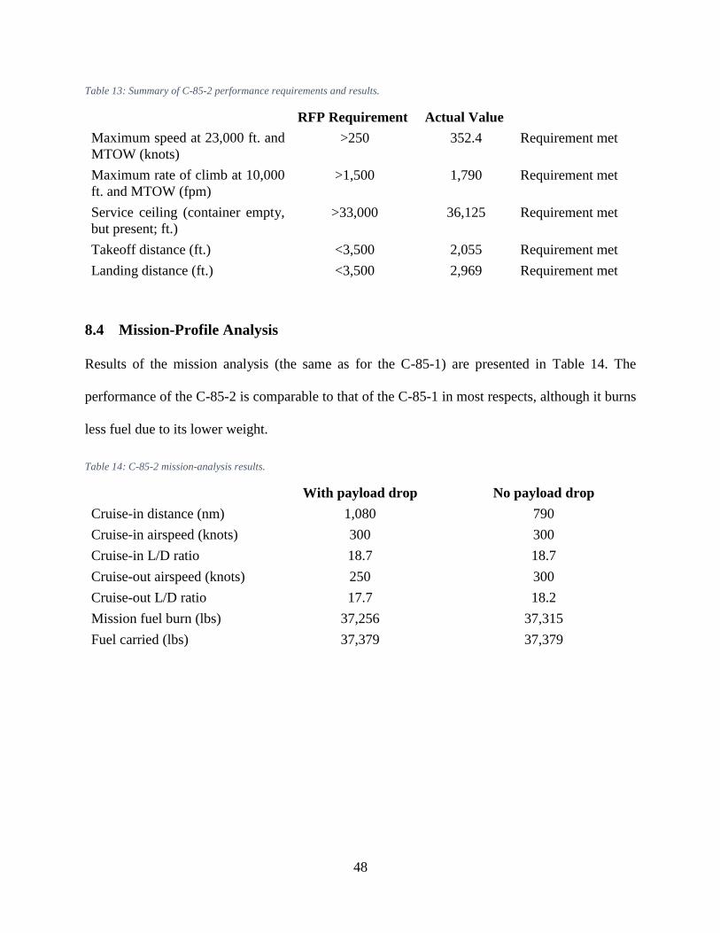
48
Table 13: Summary of C-85-2 performance requirements and results.
RFP Requirement Actual Value
Maximum speed at 23,000 ft. and
MTOW (knots)
>250 352.4 Requirement met
Maximum rate of climb at 10,000
ft. and MTOW (fpm)
>1,500 1,790 Requirement met
Service ceiling (container empty,
but present; ft.)
>33,000 36,125 Requirement met
Takeoff distance (ft.) <3,500 2,055 Requirement met
Landing distance (ft.) <3,500 2,969 Requirement met
8.4 Mission-Profile Analysis
Results of the mission analysis (the same as for the C-85-1) are presented in Table 14. The
performance of the C-85-2 is comparable to that of the C-85-1 in most respects, although it burns
less fuel due to its lower weight.
Table 14: C-85-2 mission-analysis results.
With payload drop No payload drop
Cruise-in distance (nm) 1,080 790
Cruise-in airspeed (knots) 300 300
Cruise-in L/D ratio 18.7 18.7
Cruise-out airspeed (knots) 250 300
Cruise-out L/D ratio 17.7 18.2
Mission fuel burn (lbs) 37,256 37,315
Fuel carried (lbs) 37,379 37,379
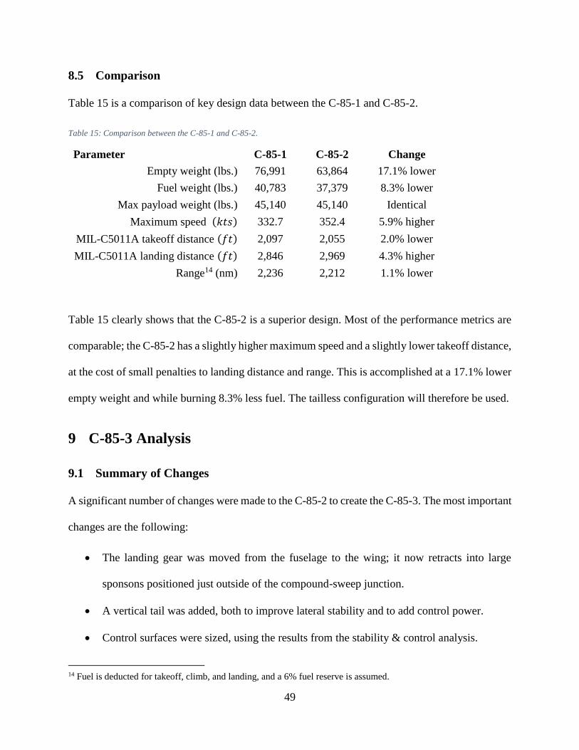
49
8.5 Comparison
Table 15 is a comparison of key design data between the C-85-1 and C-85-2.
Table 15: Comparison between the C-85-1 and C-85-2.
Parameter C-85-1 C-85-2 Change
Empty weight (lbs.) 76,991 63,864 17.1% lower
Fuel weight (lbs.) 40,783 37,379 8.3% lower
Max payload weight (lbs.) 45,140 45,140 Identical
Maximum speed (𝑘𝑡𝑠) 332.7 352.4 5.9% higher
MIL-C5011A takeoff distance (𝑓𝑡) 2,097 2,055 2.0% lower
MIL-C5011A landing distance (𝑓𝑡) 2,846 2,969 4.3% higher
Range14 (nm) 2,236 2,212 1.1% lower
Table 15 clearly shows that the C-85-2 is a superior design. Most of the performance metrics are
comparable; the C-85-2 has a slightly higher maximum speed and a slightly lower takeoff distance,
at the cost of small penalties to landing distance and range. This is accomplished at a 17.1% lower
empty weight and while burning 8.3% less fuel. The tailless configuration will therefore be used.
9 C-85-3 Analysis
9.1 Summary of Changes
A significant number of changes were made to the C-85-2 to create the C-85-3. The most important
changes are the following:
The landing gear was moved from the fuselage to the wing; it now retracts into large
sponsons positioned just outside of the compound-sweep junction.
A vertical tail was added, both to improve lateral stability and to add control power.
Control surfaces were sized, using the results from the stability & control analysis.
14 Fuel is deducted for takeoff, climb, and landing, and a 6% fuel reserve is assumed.
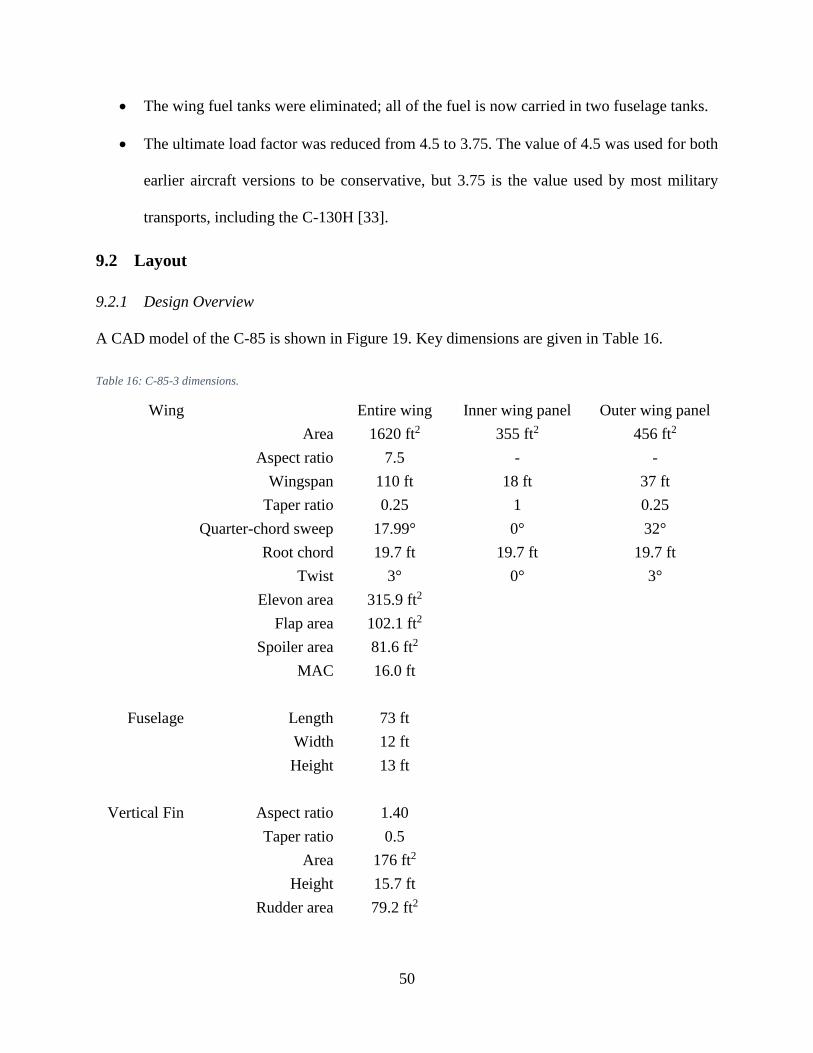
50
The wing fuel tanks were eliminated; all of the fuel is now carried in two fuselage tanks.
The ultimate load factor was reduced from 4.5 to 3.75. The value of 4.5 was used for both
earlier aircraft versions to be conservative, but 3.75 is the value used by most military
transports, including the C-130H [33].
9.2 Layout
9.2.1 Design Overview
A CAD model of the C-85 is shown in Figure 19. Key dimensions are given in Table 16.
Table 16: C-85-3 dimensions.
Wing Entire wing Inner wing panel Outer wing panel
Area 1620 ft2 355 ft2 456 ft2
Aspect ratio 7.5 - -
Wingspan 110 ft 18 ft 37 ft
Taper ratio 0.25 1 0.25
Quarter-chord sweep 17.99° 0° 32°
Root chord 19.7 ft 19.7 ft 19.7 ft
Twist 3° 0° 3°
Elevon area 315.9 ft2
Flap area 102.1 ft2
Spoiler area 81.6 ft2
MAC 16.0 ft
Fuselage Length 73 ft
Width 12 ft
Height 13 ft
Vertical Fin Aspect ratio 1.40
Taper ratio 0.5
Area 176 ft2
Height 15.7 ft
Rudder area 79.2 ft2
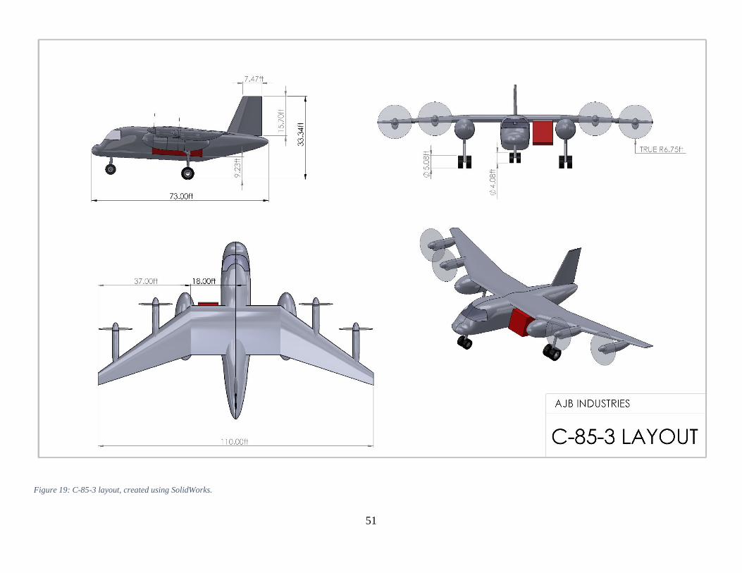
51
Figure 19: C-85-3 layout, created using SolidWorks.
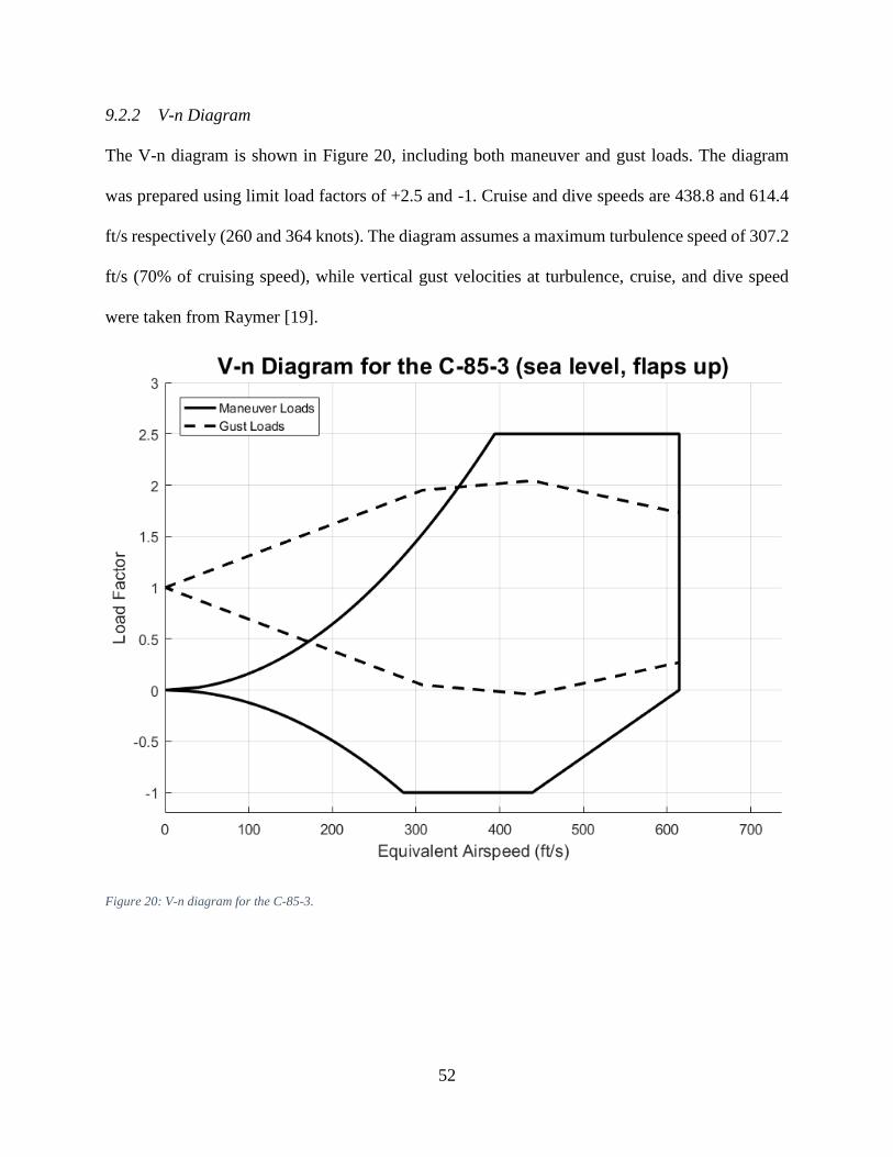
52
9.2.2 V-n Diagram
The V-n diagram is shown in Figure 20, including both maneuver and gust loads. The diagram
was prepared using limit load factors of +2.5 and -1. Cruise and dive speeds are 438.8 and 614.4
ft/s respectively (260 and 364 knots). The diagram assumes a maximum turbulence speed of 307.2
ft/s (70% of cruising speed), while vertical gust velocities at turbulence, cruise, and dive speed
were taken from Raymer [19].
Figure 20: V-n diagram for the C-85-3.

53
9.2.3 Structural Layout and Materials Selections
The C-85 utilizes a thoroughly modern structural philosophy. Most of the structure is made up of
carbon-fiber-reinforced polymer (CFRP), with additional materials (aluminum, titanium, other
composites, etc.) used where necessary. A structural cutaway can be seen in Figure 21.
Figure 21: C-85-3 structural cutaway.
Aside from the rails incorporated into the inner wing spars, the wing structure is relatively
conventional. It is of a two-spar fail-safe design, with the front and rear spar located at 15% chord
and 65% chord respectively. These spar positions were selected based on guidelines from Roskam
[34]. The outer-wing spars are made of high-strength CFRP. However, the inner wing spars double
as rails for the cargo, and as such are subjected to highly unusual cyclical loading conditions. CFRP
is not a particularly good choice for this application, as it is not very damage tolerant and tends to
fail without warning [35]. Therefore, the inner wing spars (both front and rear) are made out of
titanium.

54
Behind 15% chord, the wing skin is made out of high-modulus CFRP. The skin is integrally
stiffened, so stringers are not required [35]. However, forwards of 15% chord, aluminum is used
instead of CFRP. This is in order to reduce the vulnerability of the skin to damage, in the event of
either bird strikes or drone strikes. A recent example of a collision between a C-130 and a drone
in which the C-130 wing leading-edge was badly damaged is given in [36]. Using aluminum would
make similar damage easier both to diagnose and to repair.
The wing ribs are all made out of high-modulus CFRP. The outer wing uses a rib spacing of 36
inches. Roskam recommends a 24-inch rib spacing for transports [34], but fewer ribs are required
due to the integrally stiffened skin [35]. A 24-inch rib spacing is used for the inner wing, due to
the higher loads encountered from the cargo container.
The engine nacelles are made out of CFRP sandwich, the same material used for the 787 nacelles
[37]. As stiffness is a priority in this application, high-modulus CFRP is used instead of high-
strength CFRP. The landing-gear nacelles are made out of E-glass, a type of fiberglass. E-glass is
relatively inexpensive [35], and lends itself well to this application due to the fact that the landing-
gear nacelles are non-structural (the landing gear is attached directly to the wing spars). The
landing gear itself is of conventional aluminum-and-steel construction to lower technical risk,
while all wing control surfaces (elevons, flaps, and spoilers) are made out of high-modulus CFRP.
Finally, although wing-fuselage fairings were not defined in the CAD model, they will also be
made of E-glass.
The vertical fin uses a similar structural philosophy to that of the fuselage. It incorporates two
spars of high-strength CFRP, one at 15% and the other at 50% of the chord. The ribs are made of
high-modulus CFRP, with a rib spacing of 24 inches. The skin is made of high-modulus integrally-

55
stiffened CFRP, with aluminum used forwards of 15% of the chord. Finally, the rudder (which
extends to 50% of the chord) is made of high-modulus CFRP.
Like the wing skin, most of the fuselage skin is made of high-modulus integrally-stiffened CFRP,
with no stringers. However, the nose is made out of E-glass, in order to accommodate a weather
radar. As an auxiliary power unit (APU) is mounted in the tail, the skin in this area is made of
titanium for better heat resistance. An upper and lower keel, both made out of high-strength CFRP,
are included to transfer the loads from the wing.
The fuselage frames are spaced 30 inches apart. As with the wing ribs, this is greater than Roskam
recommends, but the integrally-stiffened wing skin means fewer framer are required. Most of the
frames are made out of high-modulus CFRP, but the last frame (to which the APU is attached) is
made of titanium. The nose landing gear, like the mains, uses conventional aluminum-and-steel
construction. Finally, the structural cutout required for the cargo container is made out of
aluminum, for better damage tolerance.
9.3 Stability & Control Analysis
Stability & control analysis was carried out, using the vortex-lattice software AVL [38]. An image
of the input geometry is shown in Figure 22.
AVL, like all vortex-lattice codes, tends to struggle with nonlifting surfaces; for this reason, the
engine nacelles and landing-gear sponsons were not included. AVL also does not have an actuator-
disk model for propellers, so engine effects were neglected. Finally, a vertical tail was required, in
order to obtain a positive value of 𝐶𝑁𝛽. The rudder also helps trim during cargo drops (where the
aerodynamics are strongly asymmetric) and during one-engine-out (OEI) situations15.
15 The engines are positioned very far out along the wing, resulting in large engine-out yawing moments. For this
reason, particular attention must be paid to OEI.

56
Figure 22: AVL input geometry.
Two cases were analyzed: a symmetric trimmed case, and a maneuver pull-up case. AVL
calculated the cruise lift coefficient from the input data (weight, altitude, cruising speed, wing
area), while the maneuver pull-up lift coefficient was set to be equal to the maximum lift
coefficient in cruise. Input conditions are summarized in Table 17, while output data is given in
Table 18.
Table 17: Input conditions for stability & control analysis in AVL.
Case Cruise Maneuver pull-up
Weight (lbs) 159,000 159,000
Velocity (knots) 260 235.4
Altitude (ft) 23,000 0
Load factor 1 2.5
Lift coefficient 0.894 1.306
CG X-location (ft) 34.5 34.5
Mach number 0.428 0.355
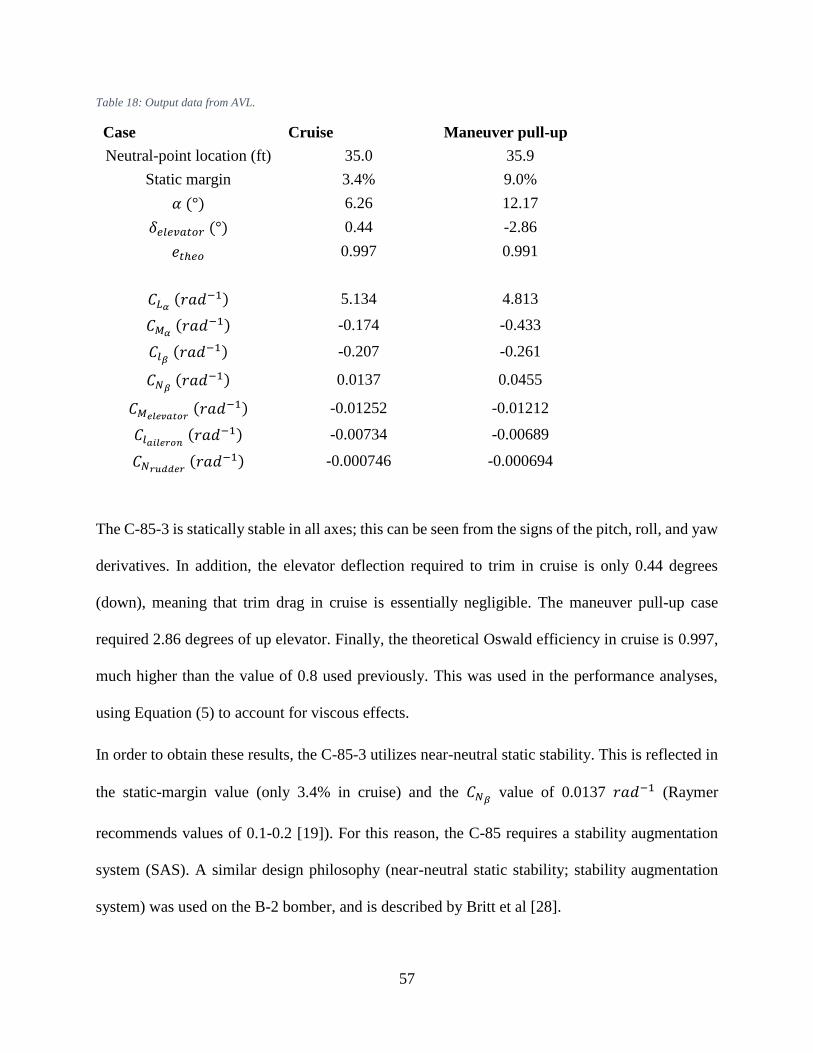
57
Table 18: Output data from AVL.
Case Cruise Maneuver pull-up
Neutral-point location (ft) 35.0 35.9
Static margin 3.4% 9.0%
𝛼 (°) 6.26 12.17
𝛿𝑒𝑙𝑒𝑣𝑎𝑡𝑜𝑟 (°) 0.44 -2.86
𝑒𝑡ℎ𝑒𝑜 0.997 0.991
𝐶𝐿𝛼 (𝑟𝑎𝑑−1) 5.134 4.813
𝐶𝑀𝛼 (𝑟𝑎𝑑−1) -0.174 -0.433
𝐶𝑙𝛽 (𝑟𝑎𝑑−1) -0.207 -0.261
𝐶𝑁𝛽 (𝑟𝑎𝑑−1) 0.0137 0.0455
𝐶𝑀𝑒𝑙𝑒𝑣𝑎𝑡𝑜𝑟 (𝑟𝑎𝑑−1) -0.01252 -0.01212
𝐶𝑙𝑎𝑖𝑙𝑒𝑟𝑜𝑛 (𝑟𝑎𝑑−1) -0.00734 -0.00689
𝐶𝑁𝑟𝑢𝑑𝑑𝑒𝑟 (𝑟𝑎𝑑−1) -0.000746 -0.000694
The C-85-3 is statically stable in all axes; this can be seen from the signs of the pitch, roll, and yaw
derivatives. In addition, the elevator deflection required to trim in cruise is only 0.44 degrees
(down), meaning that trim drag in cruise is essentially negligible. The maneuver pull-up case
required 2.86 degrees of up elevator. Finally, the theoretical Oswald efficiency in cruise is 0.997,
much higher than the value of 0.8 used previously. This was used in the performance analyses,
using Equation (5) to account for viscous effects.
In order to obtain these results, the C-85-3 utilizes near-neutral static stability. This is reflected in
the static-margin value (only 3.4% in cruise) and the 𝐶𝑁𝛽 value of 0.0137 𝑟𝑎𝑑−1 (Raymer
recommends values of 0.1-0.2 [19]). For this reason, the C-85 requires a stability augmentation
system (SAS). A similar design philosophy (near-neutral static stability; stability augmentation
system) was used on the B-2 bomber, and is described by Britt et al [28].
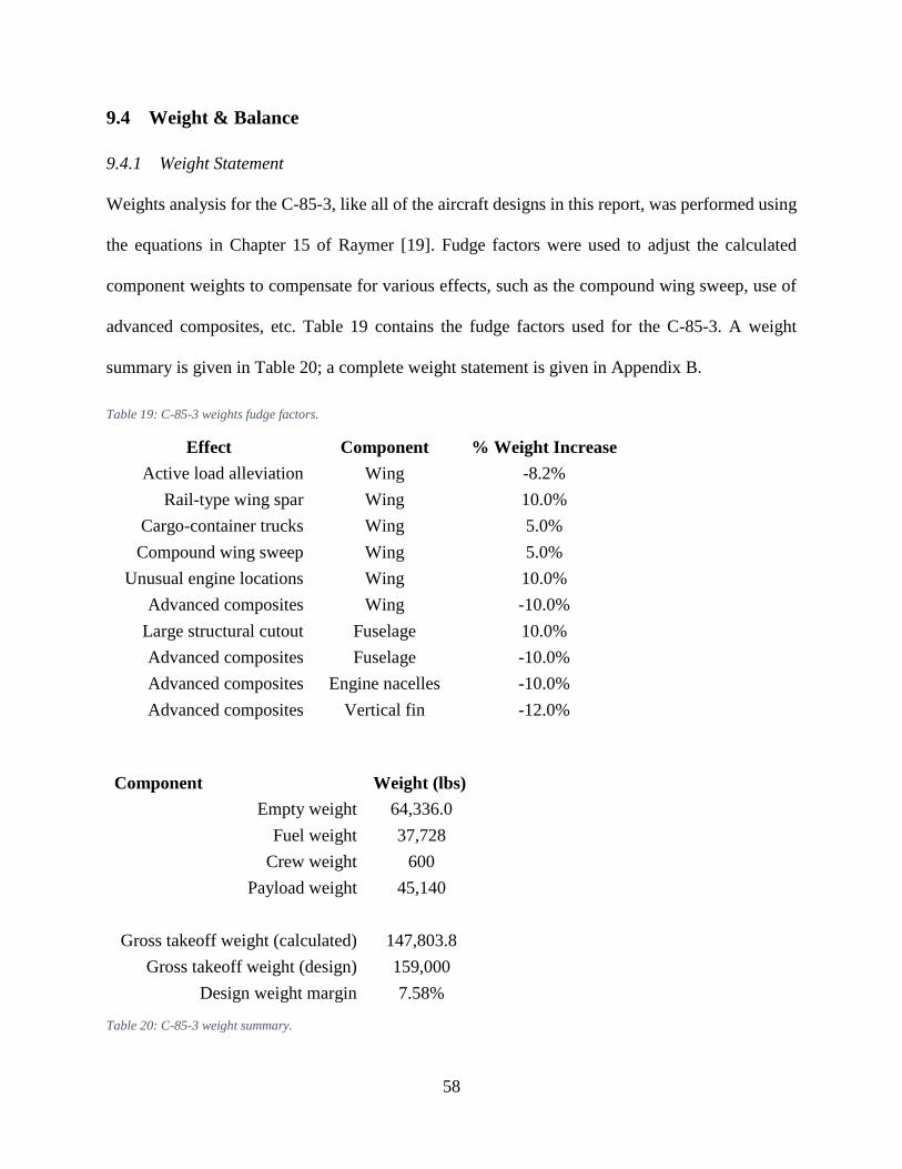
58
9.4 Weight & Balance
9.4.1 Weight Statement
Weights analysis for the C-85-3, like all of the aircraft designs in this report, was performed using
the equations in Chapter 15 of Raymer [19]. Fudge factors were used to adjust the calculated
component weights to compensate for various effects, such as the compound wing sweep, use of
advanced composites, etc. Table 19 contains the fudge factors used for the C-85-3. A weight
summary is given in Table 20; a complete weight statement is given in Appendix B.
Table 19: C-85-3 weights fudge factors.
Effect Component % Weight Increase
Active load alleviation Wing -8.2%
Rail-type wing spar Wing 10.0%
Cargo-container trucks Wing 5.0%
Compound wing sweep Wing 5.0%
Unusual engine locations Wing 10.0%
Advanced composites Wing -10.0%
Large structural cutout Fuselage 10.0%
Advanced composites Fuselage -10.0%
Advanced composites Engine nacelles -10.0%
Advanced composites Vertical fin -12.0%
Component Weight (lbs)
Empty weight 64,336.0
Fuel weight 37,728
Crew weight 600
Payload weight 45,140
Gross takeoff weight (calculated) 147,803.8
Gross takeoff weight (design) 159,000
Design weight margin 7.58%
Table 20: C-85-3 weight summary.

59
9.4.2 CG Envelope
The C-85 was designed to fly two different missions: one with a payload drop, and one without.
CG envelopes for both missions are given in Figure 23 and Figure 24 respectively. The mission
itself is given in Figure 1, with more details in Table 23 (Appendix A). A significant advantage of
the fuselage fuel tanks is the relatively small CG excursion as opposed to wing tanks. Based on
these plots, the following static-margin range was defined16: −1.36% < 𝑆𝑀 < 8.64%.
Figure 23: CG envelope (with payload drop).
16 These static-margin values are based on the neutral-point location at cruise; the neutral point during a 2.5g maneuver
pull-up is farther back, resulting in a larger static margin. See Table 18 for the neutral-point locations.

60
Figure 24: CG envelope (no payload drop).
9.5 Systems Layout
9.5.1 Cargo Loading System
The key to the C-85 design is its cargo-loading arrangement. The arrangement is shown in Figure
25 and Figure 26.
Both the front and rear spars are in the shape of rails. Each spar holds a cargo truck, with multiple
wheels to spread out the load (16 in the diagram). Since the inner wing has no taper and no twist,
the cargo container can be pulled in and out of the fuselage, along the rails. The trucks lock to the
four corners of the container, in the same manner as a straddle carrier. The left side of the cargo
container is exposed while in flight, to avoid violating the external-payload requirement.
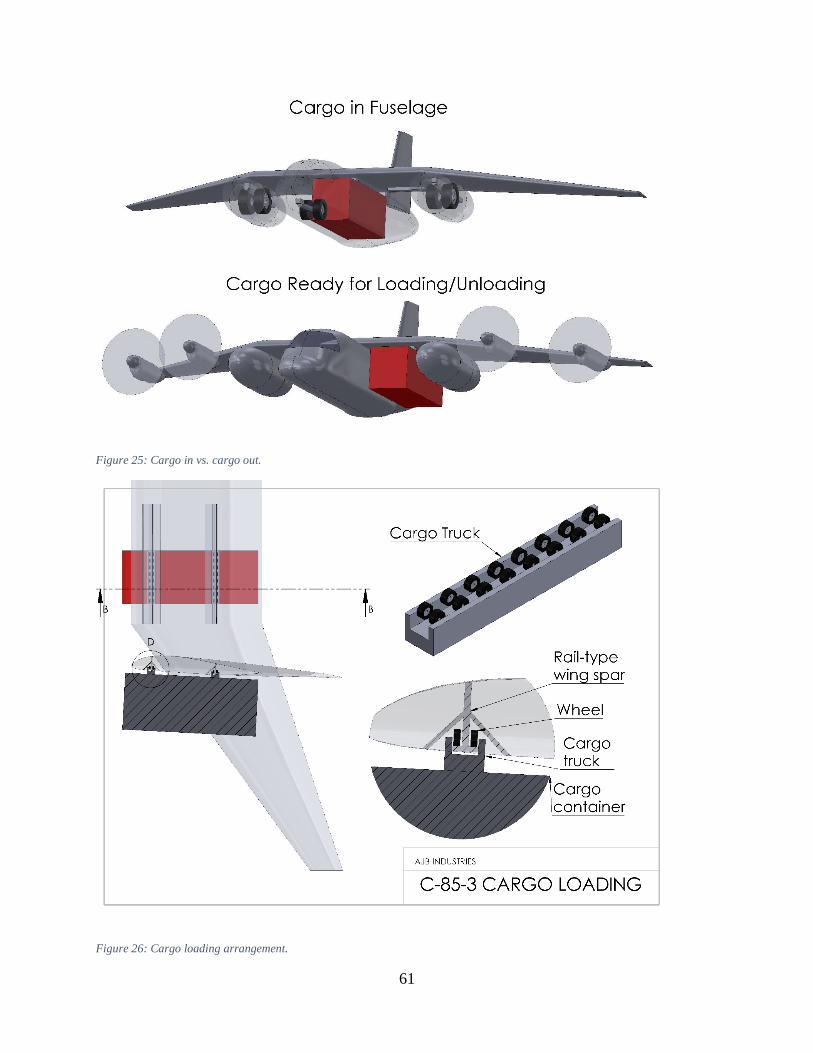
61
Figure 25: Cargo in vs. cargo out.
Figure 26: Cargo loading arrangement.

62
Three important mechanisms are not shown in the diagrams. The first is the plate which covers the
hole in the fuselage when the cargo container is removed, while the second is the doors which
cover the rails in flight. Both are sketched in Appendix C. However, some means of raising and
lowering the container is also required. This would most likely be accomplished by a winch system
built into the trucks, but the required mechanism has not yet been defined.
9.5.2 Landing Gear
The main landing gear was moved from the fuselage to the wing; it now retracts into large sponsons
positioned just outside of the compound-sweep junction. This was done for two main reasons. First
of all, as discussed in Section 5.4, the aircraft with fuselage-mounted main gear is prone to tipping
over sideways when the cargo pod is removed. Moving the gear to the wings solves this problem.
In addition, preliminary sizing of the landing gear using methods in Chapter 11 of Raymer [19]
revealed that the ideal location for the main landing gear was about 39 ft. from the nose. If fuselage-
mounted gear was retained, this would have meant placing the gear directly underneath the cargo
container and its associated structural cutout, greatly increasing weight. This problem is also
solved by moving the main gear to the wings.
The main gear is 15 feet long. It incorporates four tires, two on each strut; the tires are 61 inches
in diameter and 23 inches wide. This is somewhat larger than the C-130 main-gear tires, which are
each 56 inches in diameter and 20 inches wide. The tires were sized including a 30% margin on
diameter (for rough surfaces), and a 25% margin on load (to allow for future weight growth in the
design). The tipback angle is 22°.
The nose gear is 7 feet long. It has two tires, which were assumed to be 80% of the size of the main
tires. They are each 49 inches in diameter and 18 inches wide.

63
Both the main and nose gear retract using four-bar linkages. The nose gear retracts rearward, with
the tires rotating 90° to better fit beneath the fuel tank. Due to its simplicity, the four-bar linkage
for the nose gear is not shown. The main gear incorporates a more involved mechanism; its tires
also rotate 90° to fit inside the sponsons. Figure 27 shows the landing gear in both the retracted
and extended positions.
Figure 27: C-85-3 landing gear, both retracted and extended.
9.5.3 Fuel System
The C-85-2 carried about half of its fuel in the wings. These tanks were behind the center of
gravity, leading to a large difference in CG location for empty tanks vs. full tanks. As balance is

64
critical for a tailless configuration due to the short elevator moment arms, a decision was taken to
eliminate the wing tanks and move all of the fuel to the fuselage.
The C-85-3 carries 37,728 lbs. of fuel, about 40% of which is stored in the forward-fuselage tank.
The rear-fuselage tank carries the remainder. CG positions with the tanks both empty and full are
defined in Section 9.4.2, while an automated fuel-transfer system ensures that the CG is kept within
the desired range in all other cases. The cargo container fits in between the two tanks. An image
of the C-85 fuel tanks is given in Figure 28.
Figure 28: Isometric view of the C-85-3 fuselage, showing the seating, fuel tanks, and cargo container.
It is generally inadvisable to locate fuel tanks in the fuselage. The forward fuel tank is in a
particularly dangerous position, as both pilots would be bathed in jet fuel if the tank were to rupture

65
in a crash [19]. To alleviate these concerns, both tanks are self-sealing. The resulting weight
penalty was taken into account during weights analysis.
9.5.4 Cockpit and Personnel
The C-85-3 requires three crew members: pilot, copilot, and loadmaster. The pilot and copilot are
located in the forward fuselage, while the loadmaster is located further back. A corridor, passing
through the fuselage between the fuel tank and the loadmaster’s seat, permits access to the cargo
container during flight. This is essential if paratroops or civilian passengers are to be carried in the
container (discussed in Section 4.6). As the forward fuselage is to be pressurized, a large pressure
bulkhead (not shown) is included behind the loadmaster’s seat. The internal arrangement of the C-
85-3 is shown in the isometric view in Figure 28, as well as the side view in Figure 29.
Figure 29: C-85-3 side view, showing the internal arrangement.
The C-85-3 has a maximum approach angle of 12° (see Table 27 in Appendix F), while the angle
of attack at stall is 12.17° (Section 9.3). Crudely assuming a 40% higher angle of attack to account
for engine effects on the lift slope (Section 6.3.2), the required overnose angle is at least 29.0°.
The C-85-3 has an overnose angle of 33°, more than meeting this requirement.
The cockpit instrumentation was not defined as part of this work, due to time considerations.
However, it is expected that the C-85 will make use of a modern “glass cockpit,” with multiple
large LCD screens. An example glass cockpit (from the Boeing 787) is shown in Figure 30.

66
Figure 30: A modern glass cockpit, from the 787 [39].
9.5.5 Flight Control System
The C-85 incorporates single-slotted Fowler flaps and spoilers on the inner wing, with three-
element elevons on the outer wing. A two-element rudder is also incorporated. Control-surface
dimensions are given in Table 16, with a diagram in Figure 31. All control surfaces are
hydraulically powered.
The C-85 incorporates a fully fly-by-wire flight control system (FCS), quadruplexed17 with no
mechanical backup. The FCS includes a stability augmentation system (SAS), as well as an active
load alleviation system (both maneuver and gust). Required sensors include: angle-of-attack
sensors, sideslip-angle sensors, accelerometers, dynamic-pressure sensors, etc.
17 Four independent channels.

67
Figure 31: C-85-3 control-surface dimensions.
9.5.6 Anti-Ice
The C-85-3 incorporates a pneumatic anti-ice system, which takes bleed air from the engines to
de-ice the engine inlets and the wing leading edges. Bleed air to de-ice the vertical-fin leading edge
is obtained from the APU (discussed in the next section). This reduces the length of the pneumatic
lines; a line between the wing and the vertical fin is not required.
An electrical anti-ice system was considered, similar to that used by the 787. However, the two
most modern turboprop-powered military transports (C-130J and A-400M) both use pneumatic
anti-icing systems [13]. It is unknown to this author whether electric anti-ice systems are reliable

68
in austere environments with limited maintenance. Given that the RFP requires operation from
rough surfaces, a pneumatic system was retained to reduce technical risk.
9.5.7 Auxiliary Power Unit
The C-85-3 uses an auxiliary power unit (APU), mounted in the tail. This is in contrast to the C-
17 and the C-130J, both of which have an APU in the starboard landing-gear sponson. The APU
is used to provide power to start the engines. It also powers the electrical and hydraulic systems
while in flight; bleed air from the APU is used to de-ice the vertical-fin leading edges.
9.6 Aerodynamic Analysis
Aerodynamic-analysis data is shown in Figure 32, Figure 33, and Figure 34. Due in large part to
the landing-gear sponsons and the vertical tail, the zero-lift drag coefficient is significantly greater
relative to the C-85-2. However, the higher estimate of 𝑒𝑡ℎ𝑒𝑜 from the stability & control analysis
results in lower induced drag.
Figure 32: Cruise zero-lift drag coefficient data for the C-85-3.
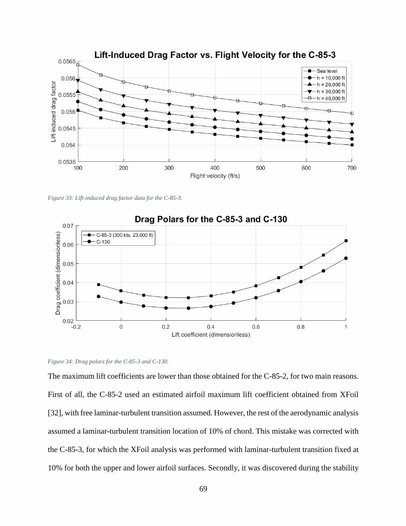
69
Figure 33: Lift-induced drag factor data for the C-85-3.
Figure 34: Drag polars for the C-85-3 and C-130.
The maximum lift coefficients are lower than those obtained for the C-85-2, for two main reasons.
First of all, the C-85-2 used an estimated airfoil maximum lift coefficient obtained from XFoil
[32], with free laminar-turbulent transition assumed. However, the rest of the aerodynamic analysis
assumed a laminar-turbulent transition location of 10% of chord. This mistake was corrected with
the C-85-3, for which the XFoil analysis was performed with laminar-turbulent transition fixed at
10% for both the upper and lower airfoil surfaces. Secondly, it was discovered during the stability

70
& control analysis that the C-85-3 required larger elevons due to the small elevator moment arm.
The size of the single-slotted Fowler flaps was correspondingly reduced. Maximum engine-off lift
coefficients are as follows:
𝐶𝐿𝑚𝑎𝑥 (𝑐𝑟𝑢𝑖𝑠𝑒) = 1.305
𝐶𝐿𝑚𝑎𝑥 (𝑡𝑎𝑘𝑒𝑜𝑓𝑓) = 1.681
𝐶𝐿𝑚𝑎𝑥 (𝑙𝑎𝑛𝑑𝑖𝑛𝑔) = 2.057
9.7 Performance Analysis
Performance results are presented in Table 21. As with the C-85-1 and C-85-2, the rate-of-climb
requirement could only be met with engines at the takeoff setting. The cruising-speed and service-
ceiling requirements were met with engines at the normal setting. All requirements are met.
Note that in large part due to the extra drag from the vertical tail and landing-gear sponsons, the
performance of the C-85-3 is significantly degraded relative to the C-85-1 and C-85-2. This is true
for maximum speed, takeoff and landing distances, and range, calling into question whether the
tailless design is really better. However, given that all performance requirements are met
(including range), and that significant weight savings are still obtained, a decision was made to
stick with the tailless configuration.
Table 21: Summary of C-85-3 performance requirements and results.
RFP Requirement Actual Value
Maximum speed at 23,000 ft. and
MTOW (knots)
>250 314.1 Requirement met
Maximum rate of climb at 10,000
ft. and MTOW (fpm)
>1,500 1,700 Requirement met
Service ceiling (container empty,
but present; ft.)
>33,000 35,047 Requirement met
Takeoff distance (ft.) <3,500 2,127 Requirement met
Landing distance (ft.) <3,500 3,311 Requirement met
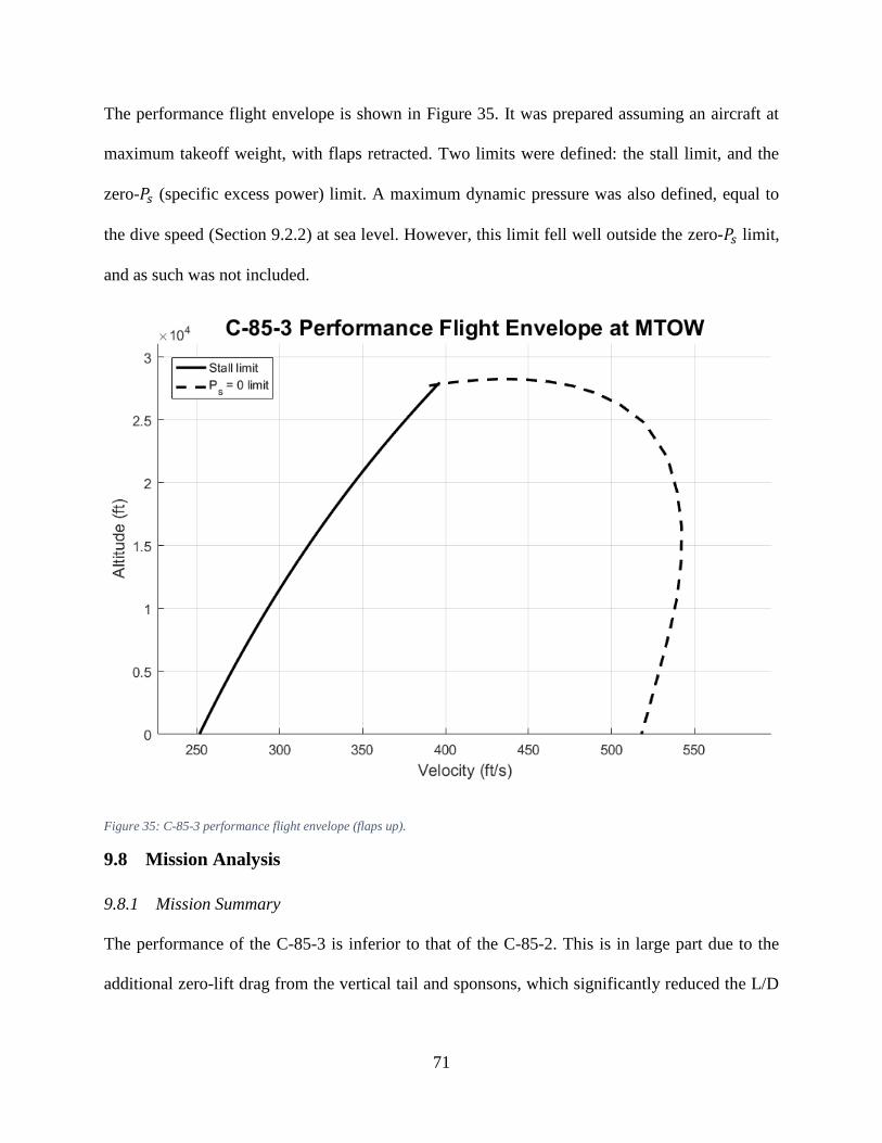
71
The performance flight envelope is shown in Figure 35. It was prepared assuming an aircraft at
maximum takeoff weight, with flaps retracted. Two limits were defined: the stall limit, and the
zero-𝑃𝑠 (specific excess power) limit. A maximum dynamic pressure was also defined, equal to
the dive speed (Section 9.2.2) at sea level. However, this limit fell well outside the zero-𝑃𝑠 limit,
and as such was not included.
Figure 35: C-85-3 performance flight envelope (flaps up).
9.8 Mission Analysis
9.8.1 Mission Summary
The performance of the C-85-3 is inferior to that of the C-85-2. This is in large part due to the
additional zero-lift drag from the vertical tail and sponsons, which significantly reduced the L/D

72
ratio in cruise. Results for both design missions are given in Table 22; fuel burn by mission
segment is given in Appendix E.
Table 22: C-85-3 mission-analysis results.
With payload drop No payload drop
Cruise-in distance (nm) 935 710
Cruise-in airspeed (knots) 260 260
Cruise-in L/D ratio 16.5 16.5
Cruise-out airspeed (knots) 250 260
Cruise-out L/D ratio 14.6 16.4
Mission fuel burn (lbs) 37,670 37,601
Fuel carried (lbs) 37,728 37,728
9.8.2 Payload-Range Chart
Figure 36: Payload-range chart for the C-85-3.

73
The payload-range chart is shown in Figure 36. The chart was prepared using the Breguet range
equation, with deductions for warm-up, takeoff, climb, descent/landing, and reserves from Table
23 (Appendix A). It becomes more efficient to cruise at a lower speed (220 knots in this case) for
small payloads, although the 260-knot cruising speed is more efficient for large payloads. Note
that the RFP requires a minimum cruising speed (with maximum payload) of 250 knots.
The C-85 has a range of 1,968 nm with maximum payload at the selected 260-knot cruising speed,
which more than meets the 1,000 nm RFP requirement.
10 Additional Work
10.1 Cost Analysis
It was stated in Section 4.7 (Design for Export) that a low unit price and operating cost for the C-
85 would be highly desirable. However, cost analysis was not conducted as part of this report due
to time considerations. Cost analysis is recommended as a next step, using the modified DAPCA
IV (Development and Production Costs of Aircraft) model found in Raymer [19].
10.2 Engine Trade Studies
A number of design features related to the engines can be improved. Firstly, as discussed in Section
4.4 (Design for Propulsion), the Pratt & Whitney PW150A engine outperforms the Allison T56-
A-15 by a wide margin in terms of size, weight, power, and fuel economy. The Allison engines
were used in this work as per RFP requirements; however, the Pratt & Whitney engines are
strongly recommended for any design work going forward.
Secondly, the landing-gear sponsons add significantly to the drag of the C-85-3. One way of
reducing drag would be to combine them with the inner engine pods. The Bombardier Dash-8 uses
a similar arrangement (see Section 3.4.2). This should be considered in a trade study.

74
Finally, the engines are mounted very far out along the wing, in order to prevent interference with
the cargo container. Mounting the engines at the wing tips should be considered in a trade study.
This approach suffers from problems due to OEI (one-engine-out), but the engine provides both
bending load alleviation and a reduction in induced drag. A similar approach was applied to the
design of a strut-braced wing transport aircraft in Gundlach et al [40]; a circulation-control system
on the vertical tail was used to counteract engine-out yawing moments.
10.3 Landing-Gear Height
The main landing gear is about 15 feet long, while the nose gear is about 7 feet long. This results
in the cargo container being more than 9 feet off the ground, more than enough for a flatbed truck
to pull up next to the aircraft for loading/unloading of the cargo (see Section 9.2.1). However, as
the maximum height of a flatbed truck is less than 5 feet [29], a 3-foot reduction in the landing-
gear height should be considered. The shorter landing gear would save weight, without impairing
loading/unloading of cargo.
10.4 Note on the Drag Polar
One of the most important equations in this work is the drag polar, which is given in Equation (3)
as: 𝐶𝐷 = 𝐶𝐷0+ 𝐾(𝐶𝐿 − 𝐶𝐿𝑚𝑖𝑛
)2. 𝐶𝐷0
and 𝐾 are typically used in aircraft conceptual design; almost
all aircraft design textbooks contain techniques for the estimation of these two parameters.
However, the 𝐶𝐿𝑚𝑖𝑛 term is unusual. Both Torenbeek [41] and Gudmundsson [35] include 𝐶𝐿𝑚𝑖𝑛
in their respective drag-polar approximations (Torenbeek in Equation 4.24, page 96;
Gudmundsson in Equation 15-6, page 667). Neither author includes a technique for its estimation.
Instead, Torenbeek states that a three-term approximation for the drag polar (𝐶𝐷0, 𝐾, 𝐶𝐿𝑚𝑖𝑛
) is
usually obtained from test data. 𝐶𝐿𝑚𝑖𝑛 is often assumed to be 0 during conceptual design, when test
data is often not available.

75
Four different methods for obtaining an estimate of induced drag were consulted as part of this
work: a semi-empirical Oswald-efficiency method, a vortex-lattice method (AVL), a two-
dimensional airfoil viscous panel code (XFoil), and test data (from the C-130). The first two of
these methods yielded a 𝐶𝐿𝑚𝑖𝑛 of 0, while the last two yielded values that were positive. See
Appendix D for the XFoil data, and Reference [4] for the C-130 test data. Since the last two
methods include the effects of viscosity, while the first two do not, it seems clear that a viscous
model is required to estimate 𝐶𝐿𝑚𝑖𝑛. Therefore, as a first approximation, a value of 𝐶𝐿𝑚𝑖𝑛
= 0.255
(the same value as the C-130) was used throughout the performance analyses, for all three aircraft
versions. This estimate should be validated with higher-fidelity estimates.
11 Conclusion
The C-85 Flying Forklift, a tailless military transport with four turboprop engines, is presented.
The design is capable of meeting all of the requirements for the 2015-2016 AIAA Undergraduate
Individual Aircraft Design Competition, including payload, service ceiling, rate of climb, takeoff
distance, and landing distance. Furthermore, the tailless design is shown to be superior to a
conventional (aft-tailed) design in terms of both weight and fuel consumption, while offering
similar performance. It has been given the provisional designation C-85, and the provisional
public-relations name Flying Forklift.
76
12 References
[1] "Military Flying Straddle Carrier," AIAA, Reston, VA, 2015.
[2] Jane's All the World's Aircraft, 1984-1985, London: IHS, 1984.
[3] B. G. Marinus and J. Poppe, "Data and Design Models for Military Turbo-Propeller
Aircraft," Aerospace Science and Technology, vol. 41, pp. 63-80, 2014.
[4] R. L. Dickinson, "[C-130] Aerodynamic Data for Structural Loads," Lockheed Aircraft
Corporation, Burbank, CA, 1953.
[5] P. Jackson, Jane's All the World's Aircraft, 2003-2004, London: IHS, 2003.
[6] P. Jackson, Jane's All the World's Aircraft: Development and Production, 2015-2016,
London: IHS, 2015.
[7] "A400M 'Grizzly' Airbus Military," Photography Obsession, [Online]. Available:
http://www.photographyobsession.co.uk/gallery3/objects/aircraft/a400m. [Accessed 26
September 2015].
[8] Jane's All the World's Aircraft, 1961-1962, London: IHS, 1961.
[9] Jane's All the World's Aircraft, 1955-1956, London: IHS, 1955.
[10] D. B., "The XC-120 Packplane: One of the USAF’s Best Failed Ideas," Strike Fighter
Consulting Inc., 8 June 2012. [Online]. Available:
http://strikefighterconsultinginc.com/blog/the-xc-120-packplane-one-of-the-usafs-best-
failed-ideas/. [Accessed 4 October 2015].
[11] Jane's All the World's Aircraft, 1950-1951, London: IHS, 1950.
[12] S. H. Evans, "Cargo-Carrier Concept - Design-logic for Airborne Logistics: The Fairchild
XC-120 Pack-plane," Flight, pp. 331-333, 1950 September 1950.
[13] P. Jackson, Jane's All the World's Aircraft: Development and Production, 2012-2013,
London: IHS, 2012.
[14] Jane's All the World's Aircraft, 1975-1976, London: IHS, 1975.
[15] L. M. Nicolai and G. E. Carichner, "Fundamentals of Aircraft and Airship Design, Volume
1 - Aircraft Design," AIAA, Reston, VA, 2010.
[16] 1996 Aerospace Source Book, New York City: Aviation Week & Space Technology, 1996.
[17] 2009 Aerospace Source Book, New York City: Aviation Week & Space Technology, 2009.
[18] I. H. Abbott, A. E. v. Doenhoff and L. S. Stevens, "NACA Report No. 824: Summary of
Airfoil Data," National Advisory Committee for Aeronautics (NACA), Langley, VA, 1945.
[19] D. P. Raymer, Aircraft Design: A Conceptual Approach, 5th ed., Reston, VA: American
Institute of Aeronautics and Astronautics, 2012.

77
[20] J. Xu and I. Kroo, "Aircraft Design with Maneuver and Gust Load Alleviation," 29th AIAA
Applied Aerodynamics Conference, Honolulu, 2011.
[21] R. J. White, " Improving the Airplane Efficiency by Use of Wing Maneuver Load
Alleviation," Journal of Aircraft, vol. 8, no. 10, pp. 769-775, 1971.
[22] R. F. O'Connell, "Design, Development, and Implementation of an Active Control System
for Load Alleviation for a Commercial Transport Airplane," Lockheed, Burbank, CA, 1979.
[23] Jane's All the World's Aircraft 1981-1982, London: IHS, 1981.
[24] J. A. Woods-Vedeler, A. S. Pototzky and S. T. Hoadley, "Rolling Maneuver Load
Alleviation Using Active Controls," Journal of Aircraft, vol. 32, no. 1, pp. 68-76, 1995.
[25] R. G. Kvaternik, K. W. Eure and J.-N. Juang, "Exploratory Studies in Generalized Predictive
Control for Active Gust Load Alleviation," NASA Langley Research Center, Hampton, VA,
2006.
[26] C. D. Regan and C. V. Jutte, "Survey of Applications of Active Control Technology for Gust
Alleviation and New Challenges for Lighter-weight Aircraft," NASA Dryden Flight
Research Center, Edwards, CA, 2012.
[27] J. Xu and I. Kroo, "Aircraft Design with Active Load Alleviation and Natural Laminar
Flow," Journal of Aircraft, vol. 51, no. 5, pp. 1532-1545, 2014.
[28] R. T. Britt, S. B. Jacobson and T. D. Arthurs, "Aeroservoelastic Analysis of the B-2 Bomber,"
Journal of Aircraft, vol. 37, no. 5, pp. 745-752, 2000.
[29] "Great Western Transportation," Flatbed Trucking, [Online]. Available:
http://www.gwtrans.com/flatbed-trucking/. [Accessed 7 November 2015].
[30] P. Grant, Preliminary Aerodynamics (lecture slides), Toronto: University of Toronto
Institute for Aerospace Studies, 2016.
[31] S. A. Brandt, R. J. Stiles, J. J. Bertin and R. Whitford, Introduction to Aeronautics: A Design
Perspective, 2nd ed., Reston, VA: AIAA, 2004.
[32] M. Drela and H. Youngren, XFoil 6.99: Subsonic Airfoil Development Medium, Cambridge,
MA: Aerospace Computational Design Lab, Massachusetts Institute of Technology (MIT),
2013.
[33] J. Roskam, Airplane Design, Part V: Component Weight Estimation, Ottawa, Kansas:
Roskam Aviation and Engineering Corp., 1985.
[34] J. Roskam, Airplane Design, Part III: Layout Design of Cockpit, Fuselage, Wing and
Empennage: Cutaways and Inboard Profiles, Ottawa, Kansas: Roskam Aviation and
Engineering Corporation, 1986.
[35] S. Gudmundsson, General Aviation Aircraft Design - Applied Methods and Procedures,
Kidlington, Oxford: Butterworth-Heinemann (Elsevier), 2014.
[36] "C-130 Cargo Plane Hits RQ-7 Shadow in Afghanistan," UAS Vision, 17 August 2011.
[Online]. Available: http://www.uasvision.com/2011/08/17/c-130-cargo-plane-hits-rq-7-
shadow-in-afghanistan/. [Accessed 9 May 2016].

78
[37] "787 Aircraft Rescue & Firefighting - Composite Structure," April 2013. [Online].
Available:
http://www.boeing.com/assets/pdf/commercial/airports/faqs/787_composite_arff_data.pdf.
[Accessed 1 May 2016].
[38] M. Drela and H. Youngren, AVL Overview, Cambridge, MA: Aerospace Computational
Design Lab, Massachusetts Institute of Technology (MIT), 2010.
[39] A. Beltyukov, "Picture of the Boeing 787-8 Dreamliner aircraft," Airliners.net, 22 June 2011.
[Online]. Available: http://www.airliners.net/photo/Boeing/Boeing-787-8-
Dreamliner/1940205/L/. [Accessed 13 May 2016].
[40] J. F. Gundlach IV, P.-A. Tetrault, F. H. Gern, A. H. Nagshineh-Pour, A. Ko, J. A. Schetz,
W. H. Mason, R. K. Kapania, B. Grossman and R. T. Haftka, "Conceptual Design Studies
of a Strut-Braced Wing Transonic Transport," Journal of Aircraft, vol. 37, no. 6, pp. 976-
983, 2000.
[41] E. Torenbeek, Advanced Aircraft Design: Conceptual Design, Analysis and Optimization of
Subsonic Civil Airplanes, Chichester: John Wiley & Sons, 2013.
[42] "The C-130J: New Hercules & Old Bottlenecks," Defense Industry Daily, 1 October 2015.
[Online]. [Accessed 4 October 2015].
[43] "F-WWMT Airbus Military Airbus A400," Planespotters.net, 1 March 2014. [Online].
Available: https://www.planespotters.net/airframe/Airbus/A400/001/F-WWMT-Airbus-
Military. [Accessed 4 October 2015].
[44] "Canada Joining the Anglosphere C-17 Club with CC-177," Defense Industry Daily, 17
November 2008. [Online]. Available: http://www.defenseindustrydaily.com/canada-joining-
the-anglosphere-c17-club-02388/. [Accessed 4 October 2015].
[45] "Container Specifications," Evergreen Marine Corp., [Online]. Available:
http://www.evergreen-marine.com/tei1/jsp/TEI1_Containers.jsp#Dry_1. [Accessed 12
October 2015].
[46] "Picture of the Fairchild XC-120 Pack Plane aircraft," Airliners.net, [Online]. Available:
http://www.airliners.net/photo/USA---Air/Fairchild-XC-120-Pack/2144978/L/. [Accessed
24 October 2015].
[47] R. Miller, "Virgin Galactic's WhiteKnightTwo caught mid-flight on video," Engadget.com,
2 May 2009. [Online]. Available: http://www.engadget.com/2009/05/02/virgin-galactics-
whiteknighttwo-caught-mid-flight-on-video/. [Accessed 7 November 2015].
[48] A. Williams, "Photo 22826 - Flybe Bombardier DHC-8-Q400 Dash 8 G-JECO at
Southampton Eastleigh," Plane-mad.com, 11 June 2011. [Online]. Available:
http://www.plane-mad.com/aviation-photos/view/flybe/dash-8-400/southampton-
eastleigh/22826.html. [Accessed 3 April 2016].
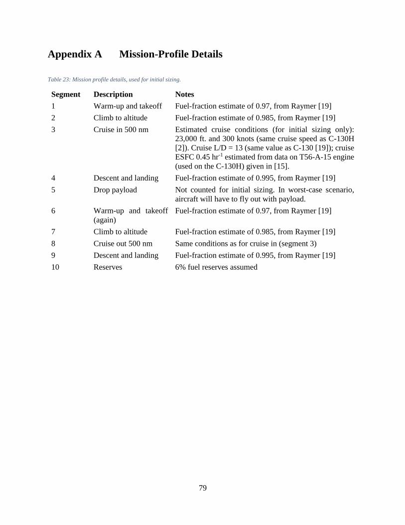
79
Appendix A Mission-Profile Details
Table 23: Mission profile details, used for initial sizing.
Segment Description Notes
1 Warm-up and takeoff Fuel-fraction estimate of 0.97, from Raymer [19]
2 Climb to altitude Fuel-fraction estimate of 0.985, from Raymer [19]
3 Cruise in 500 nm Estimated cruise conditions (for initial sizing only):
23,000 ft. and 300 knots (same cruise speed as C-130H
[2]). Cruise L/D = 13 (same value as C-130 [19]); cruise
ESFC 0.45 hr-1 estimated from data on T56-A-15 engine
(used on the C-130H) given in [15].
4 Descent and landing Fuel-fraction estimate of 0.995, from Raymer [19]
5 Drop payload Not counted for initial sizing. In worst-case scenario,
aircraft will have to fly out with payload.
6 Warm-up and takeoff
(again)
Fuel-fraction estimate of 0.97, from Raymer [19]
7 Climb to altitude Fuel-fraction estimate of 0.985, from Raymer [19]
8 Cruise out 500 nm Same conditions as for cruise in (segment 3)
9 Descent and landing Fuel-fraction estimate of 0.995, from Raymer [19]
10 Reserves 6% fuel reserves assumed

80
Appendix B Component Weight Breakdowns
Table 24: Component weight breakdowns.
C-85-1 C-85-2 C-85-3
Component Weight (lbs) Weight (lbs) Weight (lbs)
Wing 16,167.8 13,215.9 14,314.5
Horizontal tail 2189.3 n/a n/a
Vertical tail 1187.9 n/a 671.1
Fuselage 24,685.0 19,269.4 16,602.3
Main landing gear 7724.4 7,025.8 8,215.1
Nose landing gear 1144.6 1,068.3 1,158.6
Engines 13,366.3 13,366.3 13,366.3
Nacelle group 2306.1 2,197.1 2,073.6
Engine controls 245.4 196.0 196.0
Pneumatic starter 144.2 144.2 144.2
Fuel system 140.5 285.5 376.6
Flight controls 333.5 333.5 333.5
APU Installed 880.0 880.0 880.0
Instruments 402.2 347.7 349.6
Hydraulics 319.1 242.8 245.3
Electrical 900.7 789.9 798.2
Avionics 2141.4 2,141.4 2,141.4
Furnishings 1682 1,389.0 1,495.9
Air conditioning 242.6 224.2 224.2
Anti-ice 351.6 316.0 318.0
Handling gear 52.7 47.4 47.7
Military cargo handling system 384.0 384.0 384.0
Total empty weight 76,991.2 63,864.2 64,336.0
Fuel weight 40,783.0 37,379.0 37,727.7
Crew weight 600 600 600
Payload weight 45,140 45,140 45,140
Gross takeoff weight (calculated) 163,514.5 146,983.5 147,803.8
Gross takeoff weight (design) 175,800 158,000 159,000
Design weight margin 7.51% 7.50% 7.58%

81
Appendix C C-85 Cargo-Loading Sketches
The diagrams in this Appendix show the key features of the C-85 cargo-loading arrangement.
Figure 37: Top view of the C-85, showing the cargo-loading arrangement.

82
Figure 38: Diagram of the C-85 wing box. The flanges are the key to the design; they serve as rails along which the cargo container
slides during loading/unloading (like a monorail).
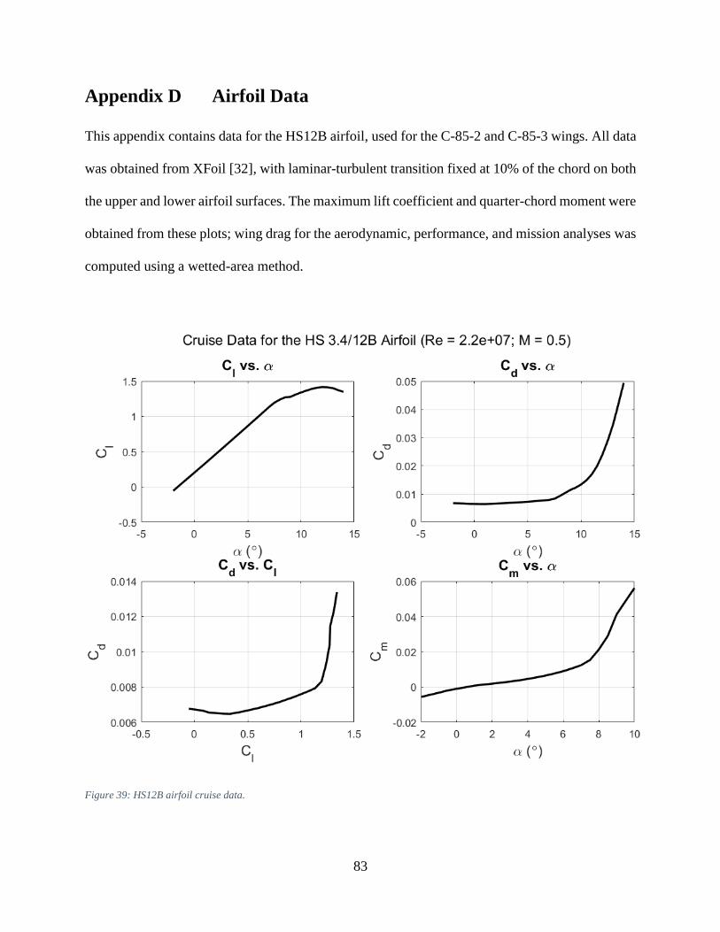
83
Appendix D Airfoil Data
This appendix contains data for the HS12B airfoil, used for the C-85-2 and C-85-3 wings. All data
was obtained from XFoil [32], with laminar-turbulent transition fixed at 10% of the chord on both
the upper and lower airfoil surfaces. The maximum lift coefficient and quarter-chord moment were
obtained from these plots; wing drag for the aerodynamic, performance, and mission analyses was
computed using a wetted-area method.
Figure 39: HS12B airfoil cruise data.

84
Figure 40: HS12B airfoil takeoff data.
Figure 41: HS12B airfoil coordinate plot

85
Appendix E Fuel Burn by Mission Segment
Table 25 contains fuel-burn data by mission segment for the C-85-3, for both design missions. See
Table 22 for cruise-in and cruise-out distances.
Table 25: Fuel burn by mission segment for the C-85-3.
Fuel Burn (lbs) Fuel Burn (lbs)
Segment Description With payload drop No payload drop
1 Warm-up and takeoff 4,770.0 4,770.0
2 Climb to altitude 2,313.5 2,313.5
3 Cruise in 13,377.0 10,269.7
4 Descent and landing 1385.4 1,416.5
5 Drop payload 0.0 0.0
6 Warm-up and takeoff (again) 2,760.4 4,206.9
7 Climb to altitude 1,338.8 2,040.4
8 Cruise out 8,668.6 9,071.8
9 Descent and landing 792.5 1,249.1
10 Reserves 2,263.7 2,263.7

86
Appendix F Detailed Performance Data for the C-85-3
This appendix contains a more detailed breakdown of the C-85-3 takeoff and landing distances.
Section 6: Analysis Methods contains a discussion of the methods used.
Table 26: Detailed breakdown of the C-85-3 takeoff-distance analysis.
Stalling speed (ft/s) 149.8
Maximum lift coefficient 3.68
Climb angle (°) 7.0
Ground roll (ft.) 943
Rotation distance (ft.) 494
Transition distance (ft.) 562
Climb distance (ft.) 127
Total takeoff distance (ft.) 2,127
Table 27: Detailed breakdown of the C-85-3 landing-distance analysis.
Technique Normal Max
Stalling speed (ft/s) 200.4 200.4
Maximum lift coefficient 2.06 2.06
Approach angle (°) 3.0 12.0
Approach distance (ft.) 757 0
Flare distance (ft.) 395 867
Delay distance (ft.) 441 220
Ground-roll distance (ft.) 1,718 1,718
Total landing distance (ft.) 3,311 2,806