the british sundial society bulletin
TRANSCRIPT
The British Sundial Society
BULLETIN
VOLUME 27(iii)
September 2015

22 BSS Bulletin Volume 27(iii) September 2015
ANALYSIS OF A ROMAN PORTABLE DIAL
FRANK H. KING
T he instrument shown in Fig. 1 is in the Museum of
the History of Science in the University of Oxford1
and is a fine example of a Roman portable sundial.
Of the several authors who have written about it, three are
of particular note: Rene Rohr,2 Michael Wright3 and
Stephen Johnston.4 Rohr gives a good introduction but
without any analysis. Wright provides a historical account
as well as a mathematical treatment. Johnston alone derives
the simple relationship between indicated hour and solar
altitude. It is noted below that the same relationship
governs the operation of the horary quadrant.
The present article introduces a novel construction which
makes reasoning about the instrument very straightforward.
It is shown that, although there are scales for setting the
latitude and the current solar declination, it is not strictly
necessary to know either. Also, the instrument is much
more universal than its designer seems to have appreciated.
Dial Components
The dial features an inner disc which sits in a recess in an
outer disc whose external diameter is 61 mm. This is
suspended by a length of cord. The most important
component is the gnomon assembly, which includes the
gnomon proper and a scale which incorporates engraved
lines; these are hour lines that indicate unequal hours. An
unequal hour is one-twelfth of the daylight period.
Simple Example – Measuring Solar Altitude
The gnomon assembly can be swivelled about a horizontal
axis which runs through the centres of the discs. The
schematic diagram in Fig. 2 shows the gnomon assembly in
profile and arranged so that it is vertical.
The gnomon is the finger at the top and O marks the edge
between its two most important faces. The discs are
assumed to be much heavier than the gnomon assembly so
that, when the instrument is hanging freely from the blue
cord, the discs (seen in cross-section) are vertical.
Fig. 1. A Roman portable sundial. Photo by permission of
the Museum of the History of Science, University of
Oxford. MHS inv. 51358.
Fig. 2. The gnomon assembly seen in profile.

BSS Bulletin Volume 27(iii) September 2015 23
A Modified Instrument – An Aid to Understanding
It is considerably easier to understand the operation of the
instrument if the gnomon assembly is replaced by the
quadrant construction shown in Fig. 3. The slope of the
quadrant is the solar altitude at noon, taken here as 40°.
There is now a single vertical disc and the sloping edge of
the quadrant is attached to a radius of that disc. The other
edge of the quadrant is horizontal and perpendicular to the
plane of the disc.
An X, Y, Z system of rectangular coordinates, with origin
O, has been added for reference purposes. The X–Y plane
is horizontal; the positive X–axis coincides with the
horizontal edge of the quadrant and the Z–axis is vertical.
The origin O equates to point O in Fig. 2. Seven hour lines
with dots at their outer ends are shown radiating from
point O at 15° intervals ranging from 0° to 90°.
Now imagine a bug stationed at point O. When the bug
sights along the 0° line it is looking at some point on the
horizon; the altitude of the line is 0°. When the bug sights
along the 90° line it is looking at some point in the sky
whose altitude is 40°.
If the bug scans along every radius from the 0° line to the
90° line its gaze must span every altitude from 0° to 40°
and this is exactly the range of altitudes of the sun on a day
when the altitude at noon is 40°.
To determine the unequal hour, the user first ensures that
the quadrant is in the plane of the sun (see Fig. 4) and then
notes which radius on the quadrant aligns with the line
from the sun to point O. (The bug will have no difficulty
but, for humans, it is better to use the gnomon assembly!)
The angular offset of this radius from the 0° line on the
quadrant is divided by 15 and the result (subtracted from 12
if it is the afternoon) gives the unequal hour.
Dots mark the positions of the engraved hour lines on the
curved surface and these dots are provisionally labelled
with angles at 15° intervals ranging from 0° to 90°. The
lines on the instrument itself are not labelled.
The instrument is classed as an altitude dial. It determines
the unequal hour from the solar altitude. When the gnomon
assembly is set as in Fig. 2, the instrument can measure
solar altitude directly. The user first checks that the
instrument is hanging vertically and then follows this
golden rule:
Ensure that the sun is in the plane of the gnomon assembly.
The user has to twist the suspension cord so that the sun
shines equally on the two cheeks of the gnomon assembly.
The shadow of the edge of the gnomon at point O will then
fall on the curved surface and, by interpolating between the
two nearest dots, the user can determine the solar altitude.
In Fig. 2, schematic suns are shown at seven altitudes from
0° to 90° at 15° intervals and, from each sun, a red line runs
to the relevant dot on the curved surface. In the diagram,
the seven suns are shown in the same plane. In general, the
azimuth of the sun changes continuously during the day
and, at each observation, the user has to face the instrument
in a different direction but, in following the golden rule, it
is never necessary to know what that direction is.
During the period of daylight, the altitude of the sun is 0° at
sunrise, then rises to a maximum at noon, before returning
to 0° again at sunset. The maximum possible noon altitude
is 90° and in that special case (and subject to two caveats)
the arrangement in Fig. 2 can be used to determine the
unequal hour by dividing the indicated altitude by 15. For
example, if the altitude is 30° then the unequal hour is 2.
The first caveat, which applies to all altitude dials, is that
the user needs to know whether it is morning or afternoon
because the sun reaches each particular altitude twice
during the course of a day. If the altitude is 30° and the sun
has gone past its highest point then the unequal hour is 10
not 2. The result obtained by dividing by 15 has to be
subtracted from 12.
The second caveat is that the underlying mathematical
model is slightly flawed. When exactly two-twelfths of the
day have elapsed, the solar altitude can be almost a degree
below 30°, a small error.
Of course, a noon altitude of 90° is a special case. If the
solar altitude at noon is, say, 40° then an observed altitude
of 30° will not indicate that we are at hour 2 or at hour 10
but at some time much closer to noon.
In general, the user has to follow another rule:
Set the gnomon assembly so that its slope (relative to
the horizontal) is the altitude of the sun at noon.
In the case illustrated in Fig. 2, the sun has an altitude of
90° at noon so the gnomon assembly has to be vertical. If
the solar altitude at noon is 40° then the slope of the
gnomon assembly has to be 40° too.
Fig. 3. The gnomon assembly replaced by a quadrant
whose angle to the horizontal matches the solar altitude at
noon, taken here as 40°. The angle to the vertical is 50°.

24 BSS Bulletin Volume 27(iii) September 2015
and it is necessary only to follow the golden rule to tell the
time. No ordinary user would think to keep a record of the
solar azimuth at each observation but anyone who does
would be in for a surprise. This is a consequence of an
inherent asymmetry which can be a distraction when trying
to understand the instrument’s behaviour.
Fig. 5 shows one way of recording the observations. In each
little diagram south is at the top, and the quadrant and the
supporting disc are seen in plan (which makes the sloping
edge of the quadrant appear foreshortened). Only four hour
lines are shown, those for 0°, 30°, 60° and 90°. The position
of the sun (strictly its azimuth) is also indicated.
Each row illustrates the orientations of the instrument at the
even-numbered daylight unequal hours from hour 0
(sunrise) to hour 12 (sunset). At hours 0, 2, 4 and 6 the sun
aligns with hour lines 0°, 30°, 60° and 90° respectively. At
Clearly the altitude of the sun at hour 0 (sunrise) matches
the altitude of the 0° line on the quadrant and the altitude at
hour 6 (noon) matches the altitude of the 90° line.
There is an underlying assumption that this correspondence
applies more generally, thus the altitude of the sun at
unequal hour u [or 12u] matches the altitude of the radius
which is offset by an angle of 15u° [or 15(12u)°] from the
reference 0° radius on the quadrant. In practice the match
may be imperfect but the error is usually small.
Inherent Asymmetry
One may imagine that first thing each morning an
assiduous user would set the slope of the quadrant to the
noon altitude for the day and leave it fixed.
Such a user might take the instrument out a dozen times in
the course of the day, quite possibly in different locations,
Fig. 4. In the central figure the shadow aligns with the sloping edge of the quadrant; the sun is shining equally on both faces
of the quadrant as required. In the figure on the left the sun is shining on the lower face. In the figure on the right it is shining
on the upper face. To correct these latter cases, the user has to rotate the supporting disc slightly about its vertical axis.
Fig. 5. Each of the three rows of figures shows plan views of the instrument (with south at the top) when making observations
at the unequal hours 0, 2,…12. In each case, a schematic sun is shown which aligns with the relevant hour line; a blue dot
indicates the actual azimuth of the sun at the unequal hour in question. In all cases the local latitude is 52° north. The solar
declinations in the three rows are +23°, 0° and –23° so the noon altitudes (and quadrant slopes) are 61°, 38° and 15°.

BSS Bulletin Volume 27(iii) September 2015 25
hours 8, 10 and 12 the sun aligns with hour lines 60°, 30°
and 0° respectively.
The three rows of figures depict the instrument at three
different settings. In the top row, the slope is 61°, in the
middle row it is 38°, and in the bottom row it is 15°.
Asymmetry is immediately apparent. In the middle row, the
orientation of the instrument is fixed all morning but it is
rotated 180° clockwise in the afternoon. In the top row the
instrument is rotated in the morning but not by very much
whereas in the afternoon it is rotated well over 180°. In the
bottom row the instrument is rotated anti-clockwise in the
morning but clockwise in the afternoon. Why?
The positions of the schematic suns give some clues. In the
middle row the sun rises due east (on the left) and sets due
west (on the right). This is the day of an equinox when the
sun travels along the celestial equator. Given that the solar
altitude at noon is 38°, we may infer that the local latitude
is 52° north (90°38°).
In the morning, the quadrant is fixed in the plane of the
celestial equator but this cannot continue after noon. At
hour 8, the instrument has to be rotated so that the 60° hour
line aligns with the line to the sun. At hour 12 (sunset) the
instrument has to be rotated so that the 0° hour line is due
west. This accounts for the 180° afternoon rotation.
The same latitude, 52° north, also applies to the top and
bottom rows; the noon solar altitudes are 61° and 15° so we
may infer that the declinations are +23° and 23° close to
the summer and winter solstices. In the top row, the sun
rises well to the north of due east and sets well to the north
of due west. In the bottom row the sun rises well to the
south of due east and sets well to the south of due west.
In each diagram, the blue spot indicates the actual solar
azimuth at the unequal hour in question. At sunrise, noon
and sunset, and also throughout the day of an equinox, the
blue spot exactly aligns with the schematic sun. In most
other cases the alignment is fairly close. The largest errors
are at the summer solstice.
The instrument ranks as a universal sundial. It can certainly
be used south of the equator. Fig. 6 shows three more rows
of diagrams and they all apply to the southern hemisphere.
South is still at the top but the sun is due north at noon.
In each case the noon solar altitude is 61°. The latitudes are
6° south in the top row, 29° south in the middle row and
52° south in the bottom row. The declinations this time are
23° (top row), 0° (middle row) and 23° (bottom row).
The middle row again depicts the day of an equinox with
the sun rising due east and setting due west but notice that
the instrument is rotated in the morning and held steady in
the afternoon. The blue spot exactly aligns with the
schematic sun throughout the day.
The top row relates to 6° south (in the tropics); the sun rises
to the north of due east and sets to the north of due west.
The instrument is rotated nearly 180° anti-clockwise in the
morning; it is rotated clockwise in the afternoon but not by
very much. The blue spot alignment is almost perfect.
The bottom row relates to a day close to the summer
solstice at 52° south and should be compared with the top
row in Fig. 5. The row of diagrams is identical to the top
row in Fig. 5 turned upside down! The instrument is rotated
well over 180° anti-clockwise in the morning and continues
being rotated anti-clockwise in the afternoons but not by
very much. The blue spot alignment is not very good.
Fig. 6. Another set of plan views of the instrument (again with south at the top) when making observations at the unequal
hours 0, 2,…12. The latitudes of the observer in the three rows are 6° south, 29° south and 52° south and the sun is due
north at noon. The solar declinations are +23°, 0° and 23° respectively. Accordingly, in each case, the noon altitude (and
quadrant slope) is 61°.
26 BSS Bulletin Volume 27(iii) September 2015
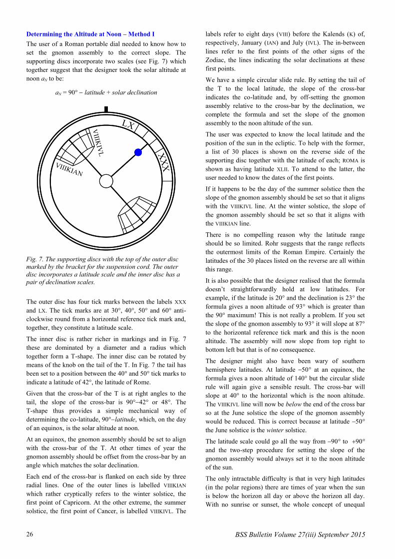
Determining the Altitude at Noon – Method I
The user of a Roman portable dial needed to know how to
set the gnomon assembly to the correct slope. The
supporting discs incorporate two scales (see Fig. 7) which
together suggest that the designer took the solar altitude at
noon aN to be:
aN = 90° latitude + solar declination
The outer disc has four tick marks between the labels XXX
and LX. The tick marks are at 30°, 40°, 50° and 60° anti-
clockwise round from a horizontal reference tick mark and,
together, they constitute a latitude scale.
The inner disc is rather richer in markings and in Fig. 7
these are dominated by a diameter and a radius which
together form a T-shape. The inner disc can be rotated by
means of the knob on the tail of the T. In Fig. 7 the tail has
been set to a position between the 40° and 50° tick marks to
indicate a latitude of 42°, the latitude of Rome.
Given that the cross-bar of the T is at right angles to the
tail, the slope of the cross-bar is 90°42° or 48°. The
T-shape thus provides a simple mechanical way of
determining the co-latitude, 90°latitude, which, on the day
of an equinox, is the solar altitude at noon.
At an equinox, the gnomon assembly should be set to align
with the cross-bar of the T. At other times of year the
gnomon assembly should be offset from the cross-bar by an
angle which matches the solar declination.
Each end of the cross-bar is flanked on each side by three
radial lines. One of the outer lines is labelled VIIIKIAN
which rather cryptically refers to the winter solstice, the
first point of Capricorn. At the other extreme, the summer
solstice, the first point of Cancer, is labelled VIIIKIVL. The
labels refer to eight days (VIII) before the Kalends (K) of,
respectively, January (IAN) and July (IVL). The in-between
lines refer to the first points of the other signs of the
Zodiac, the lines indicating the solar declinations at these
first points.
We have a simple circular slide rule. By setting the tail of
the T to the local latitude, the slope of the cross-bar
indicates the co-latitude and, by off-setting the gnomon
assembly relative to the cross-bar by the declination, we
complete the formula and set the slope of the gnomon
assembly to the noon altitude of the sun.
The user was expected to know the local latitude and the
position of the sun in the ecliptic. To help with the former,
a list of 30 places is shown on the reverse side of the
supporting disc together with the latitude of each; ROMA is
shown as having latitude XLII. To attend to the latter, the
user needed to know the dates of the first points.
If it happens to be the day of the summer solstice then the
slope of the gnomon assembly should be set so that it aligns
with the VIIIKIVL line. At the winter solstice, the slope of
the gnomon assembly should be set so that it aligns with
the VIIIKIAN line.
There is no compelling reason why the latitude range
should be so limited. Rohr suggests that the range reflects
the outermost limits of the Roman Empire. Certainly the
latitudes of the 30 places listed on the reverse are all within
this range.
It is also possible that the designer realised that the formula
doesn’t straightforwardly hold at low latitudes. For
example, if the latitude is 20° and the declination is 23° the
formula gives a noon altitude of 93° which is greater than
the 90° maximum! This is not really a problem. If you set
the slope of the gnomon assembly to 93° it will slope at 87°
to the horizontal reference tick mark and this is the noon
altitude. The assembly will now slope from top right to
bottom left but that is of no consequence.
The designer might also have been wary of southern
hemisphere latitudes. At latitude ° at an equinox, the
formula gives a noon altitude of 140° but the circular slide
rule will again give a sensible result. The cross-bar will
slope at 40° to the horizontal which is the noon altitude.
The VIIIKIVL line will now be below the end of the cross bar
so at the June solstice the slope of the gnomon assembly
would be reduced. This is correct because at latitude °
the June solstice is the winter solstice.
The latitude scale could go all the way from ° to °
and the two-step procedure for setting the slope of the
gnomon assembly would always set it to the noon altitude
of the sun.
The only intractable difficulty is that in very high latitudes
(in the polar regions) there are times of year when the sun
is below the horizon all day or above the horizon all day.
With no sunrise or sunset, the whole concept of unequal
Fig. 7. The supporting discs with the top of the outer disc
marked by the bracket for the suspension cord. The outer
disc incorporates a latitude scale and the inner disc has a
pair of declination scales.
BSS Bulletin Volume 27(iii) September 2015 27
hours fails and attempts to use the instrument will lead to
nonsense results.
Determining the Altitude at Noon – Method II
A naive user who doesn’t know the local latitude and
doesn’t know where the sun is in the ecliptic can
nevertheless set the gnomon assembly to the correct slope!
The user should take the instrument out in the morning and
align it so that the sun is in the plane of the supporting discs
instead of in the plane of the gnomon assembly. Twist the
suspension cord so that the sun shines equally on both the
vertical faces. Then, keeping the support so aligned, adjust
the gnomon assembly so that the sun is in its plane too.
This is most unlikely to give the correct slope and the
procedure should be repeated at intervals. During the
morning, the slope will gradually be increased. At noon it
will be correct and it won’t matter much if the exact
moment of noon is missed. The altitude of the sun generally
changes fairly slowly around noon. As soon as the slope
seems to need decreasing, the user will know that the sun
has passed its highest point and the gnomon assembly
should be left alone. The instrument can then be used in the
afternoon in the normal way and the slope will usually hold
good for the morning of the following day too.
The user will need to make daily checks around noon. If the
slope is too low, the sun will shine on the upper surface of
the gnomon assembly even if the supporting disc is aligned
with the sun. If the slope is too high, the indicated time will
never reach hour 6.
This approach5 works in both the northern and southern
hemispheres. It makes no use of latitude or declination or of
time of year, and dispenses with the need for any scales
other than that on the gnomon assembly. It certainly
dispenses with the need for an inner disc. A much cheaper
model could therefore have been marketed which was
easier to manufacture, very simple to set, and just as good
at indicating unequal hours!
Underlying Theory – Preliminary Error Analysis
Fig. 8 shows a simplified version of Fig. 3. The quadrant
has just three hour lines: the 0° line and the 90° line and
one in between which has an angular offset of 15u° to the
reference 0° line. For the moment u is assumed to be in the
range 0 to 6, a morning unequal hour.
It is further assumed that the noon altitude is aN° and that
this is the slope of the quadrant. The 90° line therefore
makes an angle of 90aN° to the vertical, as shown. Finally
assume that the quadrant has unit radius; this is why the
15u° line is shown with length 1.
Now suppose that au is the slope of the 15u° line relative to
the horizontal X–Y plane; au is the altitude of the point in
the sky seen by the bug when it sights along the 15u° line.
From the instrument’s point of view, at unequal hour u the
solar altitude is au whatever the latitude and declination.
The next step in the analysis is to determine the slope au in
terms of u and aN and then assess how close this value is to
the actual altitude of the sun at unequal hour u.
Taking au as the slope of the 15u° line, and the length of
the line as 1, the height of the outer end of the 15u° line
above the X–Y plane is sin(au).
Now note the red line in Fig. 8. This is the perpendicular
from the outer end of the 15u° line to the 0° line and its
length is sin(15u). Moreover, the red line is parallel to the
90° line so its slope (relative to the X–Y plane) is aN.
Accordingly, the height of the outer end of the 15u° line
above the X–Y plane is sin(15u).sin(aN).
These two values for the height can be equated:
sin(au) = sin(15u).sin(aN)
This relationship is well known. For example, exactly the
same relationship underlies the design of the horary
quadrant.6
Given the noon altitude aN the relationship enables us to
determine a solar altitude au at any unequal hour u. The
sine function takes care of the afternoon hours so there is
no need to subtract u from 12. The result may not be quite
the correct altitude but the error is normally sufficiently
small that it can be ignored. Let’s investigate the errors…
Clearly if u = 0 or u = 12 then au = 0 and if u = 6 then au
= aN
so the error is always zero at sunrise, noon and sunset. It
can also be shown that the error is always zero at the
equator (latitude 0°) whatever the time of year and is
always zero at an equinox (declination 0°) whatever the
latitude. In all other circumstances the relationship will give
a solar altitude that is not quite correct.
For example, Fig. 2 illustrated a special case in which
aN = 90°, so the relationship simplifies to au
= 15u implying
that when u = 2 the altitude is 30°. This is true on the
Fig. 8. In this variant of Fig. 3, the slope of the quadrant is
aN°, the solar altitude at noon. The hour line appropriate
for unequal hour u is also drawn; it is at an angle 15u° to
the reference 0° line.

28 BSS Bulletin Volume 27(iii) September 2015
equator at an equinox but the noon altitude can be 90°
anywhere in the tropics, for example at latitude 23° on a
day when the declination is 23°. There, at unequal hour 2,
the altitude of the sun is actually just over 29° and not 30°.
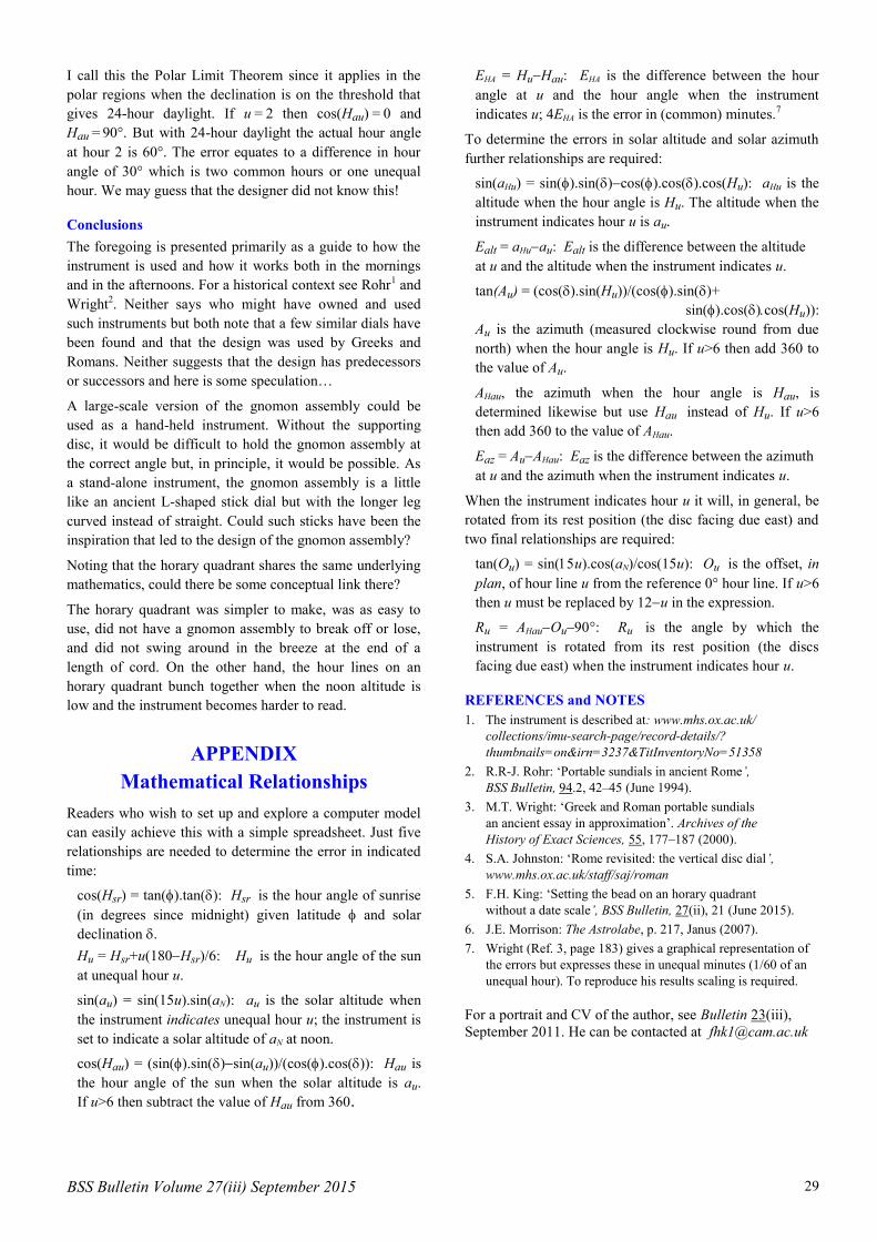
Errors – More General Considerations
In general terms, the errors are always zero at the equator
and become greater as the latitude increases.
The error can be measured in three ways. An error in
altitude means that there will be an error in azimuth (as
illustrated in Figs 5 and 6) and an error in the indicated
time. Since the error in altitude is the source of the other
two errors, it merits particular attention.
Consider the range of latitudes where the noon solar
altitude can be 46°. The range extends from latitude 21°
(when the declination is 23°) via latitude 44° (at
equinoxes, when the declination is 0°) to latitude 67° (when
the declination is +23°).
In all cases the gnomon assembly has to be set so that it
slopes at 46° to the horizontal and the expression for
sin(au) gives rise to the red curve in Fig. 9. This is exactly
right for the mid-range latitude of 44° where 46° is the
noon altitude at an equinox.
At the tropical end of the range, latitude 21°, the correct
altitude-versus-u relationship is shown by the top black
curve in Fig. 9. This almost coincides with the red curve.
The second black curve, immediately below the red curve,
applies to a British latitude 52° and again there is minimal
error. The third black curve down applies to latitude 62°
and the errors are starting to be significant.
The bottom black curve applies to latitude 67°, just inside
the Arctic circle. The errors are large and, informally, it is
easy to see why. The red curve assumed by the instrument
shows the altitude climbing steadily at roughly 10° per
(unequal) hour for four hours and then levelling off. There
is a flat peak around noon. There is also a flat bottom
around midnight but, since the sun is usually out of sight
then, this is not generally noticed. In the circumstances of
the bottom curve, there are (just) 24 hours of daylight. The
curve is noticeably more S-shaped and hence significantly
diverges from the red curve.
There is nothing special about choosing 46° for the noon
altitude. Other values would give similar curves in Fig. 9.
At a given latitude (north or south), the general rule is that
there are no errors at an equinox and the errors increase
with increasing daylight (as we approach the flat bottom).
There is also an increase with decreasing daylight but very
much less so because there is no tendency to an S-shape.
Errors – The Polar Limit Theorem
As noted, an altitude error translates into an azimuth error
and an error in indicated time. In exploring a computer
model of the Roman portable dial it was noted that at u = 2
the error in the bottom curve in Fig. 9 translated into
exactly two (common) hours. Moreover this is true
whenever latitude + declination = ±90°. Although this
observation would have been of no interest to those who
once used the instrument, the explanation is entertaining
and worth exploring…
Take the latitude as and the declination as . At the
threshold of 24-hour daylight = 90. Now, noting that
aN = 90 we have two simultaneous equations which
give = 90aN/2 and = aN/2
Using the normal formula for solar altitude we can write:
sin(au) = sin(sin( cos(cos(cos(Hau)
Here Hau is the hour angle (since midnight) at which the
sun has altitude au. Equating this to sin(15u).sin(aN) and
substituting the expressions for and above leads to:
2sin(15u).sin(aN) = sin(aN sin(aNcos(Hau)
The three instances of sin(aN) cancel and we are left with:
cos(Hau) = 12sin(15u)
This is a remarkable result. If the sum of the latitude and
declination is ±90°, the hour angle when the instrument
indicates unequal hour u is independent of latitude,
declination and noon solar altitude. The hour angle at
unequal hour u is actually 30u (24-hour daylight means 30°
per unequal hour). The result applies only in the polar
regions but theoretically it holds more generally, such as at
latitude 52° when the solar declination is (impossibly) 38°.
Fig. 9. Five examples where the noon altitude is 46°. The
red curve shows the quadrant’s understanding of the solar
altitude for unequal hours from 0 to 6. At latitude 44°, on
the day of an equinox, this exactly matches the actual solar
altitude over this period. The lowest curve shows the solar
altitude at latitude 67° on a day when the solar declination
is 23°. The sun is on the horizon at midnight but otherwise
above the horizon for all 24 hours of the day. The errors
are large. The other curves are for latitudes 21°, 52° and
62°. The errors are small.
BSS Bulletin Volume 27(iii) September 2015 29
I call this the Polar Limit Theorem since it applies in the
polar regions when the declination is on the threshold that
gives 24-hour daylight. If u = 2 then cos(Hau) = 0 and
Hau = 90°. But with 24-hour daylight the actual hour angle
at hour 2 is 60°. The error equates to a difference in hour
angle of 30° which is two common hours or one unequal
hour. We may guess that the designer did not know this!
Conclusions
The foregoing is presented primarily as a guide to how the
instrument is used and how it works both in the mornings
and in the afternoons. For a historical context see Rohr1 and
Wright2. Neither says who might have owned and used
such instruments but both note that a few similar dials have
been found and that the design was used by Greeks and
Romans. Neither suggests that the design has predecessors
or successors and here is some speculation…
A large-scale version of the gnomon assembly could be
used as a hand-held instrument. Without the supporting
disc, it would be difficult to hold the gnomon assembly at
the correct angle but, in principle, it would be possible. As
a stand-alone instrument, the gnomon assembly is a little
like an ancient L-shaped stick dial but with the longer leg
curved instead of straight. Could such sticks have been the
inspiration that led to the design of the gnomon assembly?
Noting that the horary quadrant shares the same underlying
mathematics, could there be some conceptual link there?
The horary quadrant was simpler to make, was as easy to
use, did not have a gnomon assembly to break off or lose,
and did not swing around in the breeze at the end of a
length of cord. On the other hand, the hour lines on an
horary quadrant bunch together when the noon altitude is
low and the instrument becomes harder to read.
APPENDIX
Mathematical Relationships
Readers who wish to set up and explore a computer model
can easily achieve this with a simple spreadsheet. Just five
relationships are needed to determine the error in indicated
time:
cos(Hsr) = tan().tan(): Hsr is the hour angle of sunrise
(in degrees since midnight) given latitude and solar
declination .
Hu = Hsr+u(180Hsr)/6: Hu is the hour angle of the sun
at unequal hour u.
sin(au) = sin(15u).sin(aN): au is the solar altitude when
the instrument indicates unequal hour u; the instrument is
set to indicate a solar altitude of aN at noon.
cos(Hau) = (sin().sin()sin(au))/(cos().cos()): Hau is
the hour angle of the sun when the solar altitude is au.
If u>6 then subtract the value of Hau from 360.
EHA = HuHau: EHA is the difference between the hour
angle at u and the hour angle when the instrument
indicates u; 4EHA is the error in (common) minutes.7
To determine the errors in solar altitude and solar azimuth
further relationships are required:
sin(aHu) = sin().sin()cos().cos().cos(Hu): aHu is the
altitude when the hour angle is Hu. The altitude when the
instrument indicates hour u is au.
Ealt = aHuau: Ealt is the difference between the altitude
at u and the altitude when the instrument indicates u.
tan(Au) = (cos().sin(Hu))/(cos().sin()+
sin().cos()cos(Hu)):
Au is the azimuth (measured clockwise round from due
north) when the hour angle is Hu. If u>6 then add 360 to
the value of Au.
AHau, the azimuth when the hour angle is Hau, is
determined likewise but use Hau instead of Hu. If u>6
then add 360 to the value of AHau.
Eaz = AuAHau: Eaz is the difference between the azimuth
at u and the azimuth when the instrument indicates u.
When the instrument indicates hour u it will, in general, be
rotated from its rest position (the disc facing due east) and
two final relationships are required:
tan(Ou) = sin(u).cos(aN)/cos(15u): Ou is the offset, in
plan, of hour line u from the reference 0° hour line. If u>6
then u must be replaced by 12u in the expression.
Ru = AHauOu°: Ru is the angle by which the
instrument is rotated from its rest position (the discs
facing due east) when the instrument indicates hour u.
REFERENCES and NOTES
1. The instrument is described at: www.mhs.ox.ac.uk/
collections/imu-search-page/record-details/?
thumbnails=on&irn=3237&TitInventoryNo=51358
2. R.R-J. Rohr: ‘Portable sundials in ancient Rome’,
BSS Bulletin, 94.2, 42–45 (June 1994).
3. M.T. Wright: ‘Greek and Roman portable sundials
an ancient essay in approximation’. Archives of the
History of Exact Sciences, 55, 177–187 (2000).
4. S.A. Johnston: ‘Rome revisited: the vertical disc dial’,
www.mhs.ox.ac.uk/staff/saj/roman
5. F.H. King: ‘Setting the bead on an horary quadrant
without a date scale’, BSS Bulletin, 27(ii), 21 (June 2015).
6. J.E. Morrison: The Astrolabe, p. 217, Janus (2007).
7. Wright (Ref. 3, page 183) gives a graphical representation of
the errors but expresses these in unequal minutes (1/60 of an
unequal hour). To reproduce his results scaling is required.
For a portrait and CV of the author, see Bulletin 23(iii),
September 2011. He can be contacted at [email protected]