the 1090mhz riddle - mode-s.orgmode-s.org/decode/book-the_1090mhz_riddle-junzi_sun.pdf · the...
TRANSCRIPT

The 1090MHz Riddle
An open-access book about decoding Mode-S and ADS-B data
BY
Junzi Sun
GNU GPL v2 open-source license.

Preface
Begun with a frustration on the lack of technical public information on ADS-B and Mode-S in the year 2015, I created a live online document to record my understanding of ADS-Bdata. Previously, this was known as “ADS-B Decoding Guide” project. Together with thetutorial, we also developed its related Python library, the pyModeS. With time, I receivedmany feedbacks, compliments, and contributions from open-source community users.
Since the beginning of 2017, the interests of tapping into Enhanced Mode-S (EHS) databrought us a whole new chapter of Mode-S inference and decoding into the pyModeS.This also enriches the “ADS-B” guide. With the advance in this area, I am planning tocompile a more comprehensive online book to cover both ADS-B and Mode-S decodingand related topic.
That’s the starting of this new repository. I am also starting to host the online book onmy own server to allow more flexibility of editing and publishing. You can read the mostup-to-date book on mode-s.org.
Oh, it is still GNU GPL. It was great to see the pull requests from different contributorspreviously. I am looking forward to seeing more comments and pulls from the community.Enjoy!

Contents
1. ADS-B 41.1. ADS-B Basics . . . . . . . . . . . . . . . . . . . . . . . . . . . . . . . . . . . 4
1.1.1. Message structure . . . . . . . . . . . . . . . . . . . . . . . . . . . . . . 41.1.2. ICAO address . . . . . . . . . . . . . . . . . . . . . . . . . . . . . . . . 51.1.3. ADS-B message types . . . . . . . . . . . . . . . . . . . . . . . . . . . . 51.1.4. ADS-B Checksum . . . . . . . . . . . . . . . . . . . . . . . . . . . . . . 6
1.2. Aircraft Identification . . . . . . . . . . . . . . . . . . . . . . . . . . . . . . . 61.3. Compact Position Reporting . . . . . . . . . . . . . . . . . . . . . . . . . . . 8
1.3.1. The CPR and functions . . . . . . . . . . . . . . . . . . . . . . . . . . . 91.4. Airborne Positions . . . . . . . . . . . . . . . . . . . . . . . . . . . . . . . . 10
1.4.1. Globally unambiguous position (decoding with two messages) . . . . . 111.4.2. Locally unambiguous position (decoding with one message) . . . . . . 15
1.5. Airborne Velocity . . . . . . . . . . . . . . . . . . . . . . . . . . . . . . . . . 171.5.1. Subtype 1 (Ground Speed) . . . . . . . . . . . . . . . . . . . . . . . . . 181.5.2. Subtype 3 (Airspeed) . . . . . . . . . . . . . . . . . . . . . . . . . . . . 20
2. Advanced ADS-B topics 232.1. ADS-B versions . . . . . . . . . . . . . . . . . . . . . . . . . . . . . . . . . . 23
2.1.1. Identify the ADS-B Version . . . . . . . . . . . . . . . . . . . . . . . . . 242.2. Aircraft Operation Status . . . . . . . . . . . . . . . . . . . . . . . . . . . . . 242.3. Uncertainty and accuracy . . . . . . . . . . . . . . . . . . . . . . . . . . . . 27
2.3.1. Version 0 . . . . . . . . . . . . . . . . . . . . . . . . . . . . . . . . . . . 282.3.2. Version 1 . . . . . . . . . . . . . . . . . . . . . . . . . . . . . . . . . . . 312.3.3. Version 2 . . . . . . . . . . . . . . . . . . . . . . . . . . . . . . . . . . . 34
3. Ehanced Mode-S 383.1. Enhanced Mode-S Basics . . . . . . . . . . . . . . . . . . . . . . . . . . . . . 38
3.1.1. Downlink Format and message structure . . . . . . . . . . . . . . . . . 383.1.2. Parity and ICAO address recovery . . . . . . . . . . . . . . . . . . . . . 393.1.3. BDS (Comm-B Data Selector) . . . . . . . . . . . . . . . . . . . . . . . 40
3.2. Aircraft identification (BDS 2,0) . . . . . . . . . . . . . . . . . . . . . . . . . 403.3. Selected intention (BDS 4,0) . . . . . . . . . . . . . . . . . . . . . . . . . . . 413.4. Track and turn (BDS 5,0) . . . . . . . . . . . . . . . . . . . . . . . . . . . . 433.5. Heading and speed (BDS 6,0) . . . . . . . . . . . . . . . . . . . . . . . . . . 45
4. About the book 484.1. Related resources . . . . . . . . . . . . . . . . . . . . . . . . . . . . . . . . . 484.2. Contributors . . . . . . . . . . . . . . . . . . . . . . . . . . . . . . . . . . . . 484.3. Contact . . . . . . . . . . . . . . . . . . . . . . . . . . . . . . . . . . . . . . 484.4. References . . . . . . . . . . . . . . . . . . . . . . . . . . . . . . . . . . . . . 49

Chapter 1
ADS-B
ADS-B is short for Automatic Dependent SurveillanceBroadcast. It is a satellite basedsurveillance system. Aircraft position, velocity, together with identification are transmit-ted through Mode-S Extended Squitter (1090 MHz).
Majority of the aircraft nowadays are broadcasting ADS-B messages constantly. Thereare many ways you can set up you own receiver and antenna to start tapping into thosesignals (DVB-T usb stick, ModeSBeast, Raspberry Pi, RadarScape, etc).
1.1. ADS-B Basics
1.1.1. Message structure
An ADS-B message is 112 bits long, and consists of 5 parts.
+--------+--------+-----------+--------------------------+---------+
| DF 5 | ** 3 | ICAO 24 | DATA 56 | PI 24 |
+--------+--------+-----------+--------------------------+---------+
Any ADS-B must start with the Downlink Format 17, or 18 in case of TIS-B message.They correspond to 10001 or 10010 in binary for the first 5 bits. Bits 6-8 are used as anadditional identifier, which has different meanings within each ADS-B subtype.
In following Table 1.1, the key information of a ADS-B message is listed.
Table 1.1. Structure of ADS-B messages
nBits Bits Abbr. Name
5 1 - 5 DF Downlink Format3 6 - 8 CA Capability (additional identifier)24 9 - 32 ICAO ICAO aircraft address56 33 - 88 DATA Data
[33 - 37] [TC] Type code24 89 - 112 PI Parity/Interrogator ID
It is worth noting that the ADS-B Extended Squitter sent from a Mode S transponder useDownlink Format 17 ( DF=17 ). Non-Transponder-Based ADS-B Transmitting Subsystemsand TIS-B Transmitting equipment use Downlink Format 18 ( DF=18 ). By using DF=18

1.1. ADS-B Basics 5
instead of DF=17 , an ADS-B/TIS-B Receiving Subsystem will know that the messagecomes from equipment that cannot be interrogated.
An example:
Raw message in hexadecimal:
8D4840D6202CC371C32CE0576098
[00100]0000010110011
00001101110001110000
110010110011100000
-----+------------+--------------+----------------------+--------------
HEX | 8D | 4840D6 | 202CC371C32CE0 | 576098
-----+------------+--------------+----------------------+--------------
BIN | 10001 101 | 010010000100 | [00100]0000010110011 | 010101110110
| | 000011010110 | 00001101110001110000 | 000010011000
| | | 110010110011100000 |
-----+------------+--------------+----------------------+--------------
DEC | 17 5 | | [4] ............... |
-----+------------+--------------+----------------------+--------------
| DF CA | ICAO | [TC] --- DATA ----- | PI
-----+------------+--------------+----------------------+--------------
1.1.2. ICAO address
In each ADS-B message, the sender (originating aircraft) can be identified using the ICAOaddress. It is located from 9 to 32 bits in binary (or 3 to 8 in hexadecimal). In the exampleabove, it is 4840D6 or 010010000100 .
An unique ICAO address is assigned to each Mode-S transponder of an aircraft. Thusthis is a unique identifier for each aircraft. You can use the query tool (World AircraftDatabase) from mode-s.org to find out more about the aircraft with a given ICAO address.For instance, using the previous ICAO 4840D6 example, it will return the result of aFokker 70 with registration of PH-KZD .
In addition, you can download the database from the aforementioned website in CSVformat.
1.1.3. ADS-B message types
To identify what information is contained in an ADS-B message, we need to take a look atthe Type Code of the message, indicated at bits 33 - 37 of the ADS-B message (or first 5
bits of the DATA segment).
In following Table 1.2, the relationships between each Type Code and its information
contained in the DATA segment are shown.

6 1. ADS-B
Table 1.2. ADS-B Type Code and content
Type Code Content
1 - 4 Aircraft identification5 - 8 Surface position9 - 18 Airborne position (w/ Baro Altitude)19 Airborne velocities20 - 22 Airborne position (w/ GNSS Height)23 - 27 Reserved28 Aircraft status29 Target state and status information31 Aircraft operation status
1.1.4. ADS-B Checksum
ADS-B uses a cyclic redundancy check to validate the correctness of the received message,where the last 24 bits are the parity bits. The following pseudo-code describes the CRCprocess:
GENERATOR = 1111111111111010000001001
MSG = binary("8D4840D6202CC371C32CE0576098") # total 112 bits
FOR i FROM 0 TO 88: # 112 - 24 parity bits
if MSG[i] is 1:
MSG[i:i+24] = MSG[i:i+24] ^ GENERATOR
CRC = MSG[-24:] # last 24 bits
IF CRC not 0:
MSG is corrupted
For the implementation of CRC encoder in Python, refer to the pyModeS library function:pyModeS.crc()
A comprehensive documentation on Mode-S parity coding can be found:
Gertz, Jeffrey L. Fundamentals of mode s parity coding. No. ATC-117.
MASSACHUSETTS INST OF TECH LEXINGTON LINCOLN LAB, 1984. APA
1.2. Aircraft Identification
An aircraft identification message has DF: 17 or 18 , and TC: 1 to 4 , the 56-bitDATA field is configured as follows:
1.2. Aircraft Identification 7
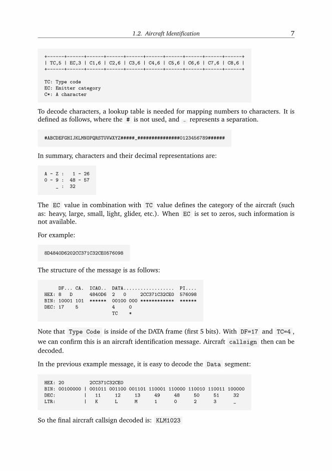
+------+------+------+------+------+------+------+------+------+------+
| TC,5 | EC,3 | C1,6 | C2,6 | C3,6 | C4,6 | C5,6 | C6,6 | C7,6 | C8,6 |
+------+------+------+------+------+------+------+------+------+------+
TC: Type code
EC: Emitter category
C*: A character
To decode characters, a lookup table is needed for mapping numbers to characters. It isdefined as follows, where the # is not used, and represents a separation.
#ABCDEFGHIJKLMNOPQRSTUVWXYZ#####_###############0123456789######
In summary, characters and their decimal representations are:
A - Z : 1 - 26
0 - 9 : 48 - 57
_ : 32
The EC value in combination with TC value defines the category of the aircraft (suchas: heavy, large, small, light, glider, etc.). When EC is set to zeros, such information isnot available.
For example:
8D4840D6202CC371C32CE0576098
The structure of the message is as follows:
DF... CA. ICAO.. DATA.................. PI....
HEX: 8 D 4840D6 2 0 2CC371C32CE0 576098
BIN: 10001 101 ****** 00100 000 ************ ******
DEC: 17 5 4 0
TC *
Note that Type Code is inside of the DATA frame (first 5 bits). With DF=17 and TC=4 ,
we can confirm this is an aircraft identification message. Aircraft callsign then can bedecoded.
In the previous example message, it is easy to decode the Data segment:
HEX: 20 2CC371C32CE0
BIN: 00100000 | 001011 001100 001101 110001 110000 110010 110011 100000
DEC: | 11 12 13 49 48 50 51 32
LTR: | K L M 1 0 2 3 _
So the final aircraft callsign decoded is: KLM1023

8 1. ADS-B
For detailed codes in Python, refer to the pyModeS library function: pyModeS.adsb.callsign()
1.3. Compact Position Reporting
The position information in ADS-B messages is encoded in a compact position reporting(CPR) format. The general idea behind CPR is to be able to encode more coordinatedecimals using less bits. It is achieved by trading global position ambiguity and time withlocal position accuracy.
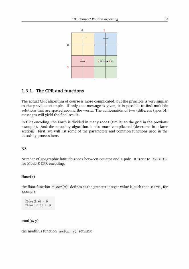
An easy example to understand the principle behind CPR:
Imaging the world is constructed by 16 grid, which we have divided into two levels,each level is encoded with two bits. Higher levels in color are 00 (yellow), 01 (blue),10 (red), 11 (green). And within each color grid, the lower levels are also encoded
similarly.
Then each grid can be represented as 4 digits from 0000 to 1111 . Now, we want todescribe the movement indicated as the arrows in the green grids 1100 -> 1101 , butwe only have 3 bits to encode each position.
It is easy to see that the high 2 bits appeared in all positions, so we can define a structureto do the following:
1. The last two bits shall represent the local position
2. The combination of first digit from two messages defines the higher grid
Then the two messages can be sent as 1 00 -> 1 01 .
From lower bits 00 -> 01 , we have four different possibility of movement as shownin dashed arrows, and from the two first bits combination 11 , we know that the arrowshall represent the movement in the green grids:
1.3. Compact Position Reporting 9
1.3.1. The CPR and functions
The actual CPR algorithm of course is more complicated, but the principle is very similarto the previous example. If only one message is given, it is possible to find multiplesolutions that are spaced around the world. The combination of two (different types of)messages will yield the final result.
In CPR encoding, the Earth is divided in many zones (similar to the grid in the previousexample). And the encoding algorithm is also more complicated (described in a latersection). First, we will list some of the parameters and common functions used in thedecoding process here.
NZ
Number of geographic latitude zones between equator and a pole. It is set to NZ = 15
for Mode-S CPR encoding.
floor(x)
the floor function floor(x) defines as the greatest integer value k, such that k<=x , forexample:
floor(5.6) = 5
floor(-5.6) = -6
mod(x, y)
the modulus function mod(x, y) returns:
10 1. ADS-B
x− y · floor(xy) (1.1)
where y can not be zero
NL(lat)
Denotes the “number of longitude zones” function, given the latitude angle lat . Thereturned integer value is constrained within [1, 59] , calculated as:
NL(lat) = floor
2π
arccos(1− 1−cos( π2·NZ )
cos2( π180 ·lat) )
(1.2)
For latitudes that are close to the equator or the poles, one of following values is returned:
lat = 0 -> NL = 59
lat = +87 -> NL = 2
lat = -87 -> NL = 2
lat > +87 -> NL = 1
lat < -87 -> NL = 1
1.4. Airborne Positions
An aircraft airborne position message has downlink format 17 (or 18 ) with type codefrom 9 to 18
Messages are composed as shown in following Table 1.3
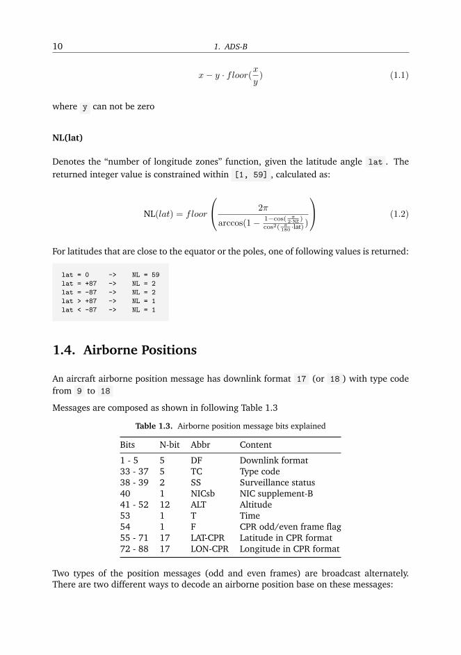
Table 1.3. Airborne position message bits explained
Bits N-bit Abbr Content
1 - 5 5 DF Downlink format33 - 37 5 TC Type code38 - 39 2 SS Surveillance status40 1 NICsb NIC supplement-B41 - 52 12 ALT Altitude53 1 T Time54 1 F CPR odd/even frame flag55 - 71 17 LAT-CPR Latitude in CPR format72 - 88 17 LON-CPR Longitude in CPR format
Two types of the position messages (odd and even frames) are broadcast alternately.There are two different ways to decode an airborne position base on these messages:

1.4. Airborne Positions 11
1. Unknown position, using both type of messages (aka globally unambiguous posi-tion)
2. Knowing previous position, using only one message (aka locally unambiguous posi-tion)
Note: The definition of functions NL(lat) , floor(x) , and mod(x,y) are described inthe CPR chapter.
1.4.1. Globally unambiguous position (decoding with two messages)
odd or even message?
For each frame, bit 54 determines whether it is an odd or even frame:
0 -> Even frame
1 -> Odd frame
For example, the two following messages are received:
8D40621D58C382D690C8AC2863A7
8D40621D58C386435CC412692AD6
| | ICAO24 | DATA | CRC |
|----|--------|----------------|--------|
| 8D | 40621D | 58C382D690C8AC | 2863A7 |
| 8D | 40621D | 58C386435CC412 | 692AD6 |
The payload data in binary formation:
| DATA |
|============================================================================|
| TC | ... | ALT | T | F | CPR-LAT | CPR-LON |
|-------|-----|--------------|---|---|-------------------|-------------------|
| 01011 | 000 | 110000111000 | 0 | 0 | 10110101101001000 | 01100100010101100 |
| 01011 | 000 | 110000111000 | 0 | 1 | 10010000110101110 | 01100010000010010 |
In both messages we can find DF=17 and TC=11 , with the same ICAO24 address40621D . So, those two frames are valid for decoding the positions of this aircraft.
Assume the first message is the newest message received.

12 1. ADS-B
The CPR representation of coordinates
| F | CPR Latitude | CPR Longitude |
|---|-------------------|-------------------|
| 0 | 10110101101001000 | 01100100010101100 | -> newest
| 1 | 10010000110101110 | 01100010000010010 |
|---|-------------------|-------------------|
In decimal:
|---|-------------------|-------------------|
| 0 | 93000 | 51372 |
| 1 | 74158 | 50194 |
|---|-------------------|-------------------|
CPR_LAT_EVEN: 93000 / 131072 -> 0.7095
CPR_LON_EVEN: 51372 / 131072 -> 0.3919
CPR_LAT_ODD: 74158 / 131072 -> 0.5658
CPR_LON_ODD: 50194 / 131072 -> 0.3829
Since CPR latitude and longitude are encoded in 17 bits, 131072 (217) is the maximumvalue.
Calculate the latitude index j
Use the following equation:
j = floor
(59 · LatcprEven − 60 · LatcprOdd +
1
2
)(1.3)
where j is set 8.
Calculate latitude
First, two constants will be used:
dLateven =360
4 ·NZ=
360
60
dLatodd =360
4 ·NZ − 1=
360
59(1.4)
Then we can use the following equations to compute the relative latitudes:

1.4. Airborne Positions 13
Lateven = dLateven · [mod(j, 60) + LatcprEven]
Latodd = dLatodd · [mod(j, 59) + LatcprOdd] (1.5)
For the southern hemisphere, values will fall from 270 to 360 degrees. We need to makesure the latitude is within the range [-90, +90] :
Lateven = Lateven − 360 if (Lateven ≥ 270)
Latodd = Latodd − 360 if (Latodd ≥ 270) (1.6)
Final latitude is chosen depending on the time stamp of the frames, the newest one, isused:
Lat =
{Lateven if (Teven ≥ Todd)
Latodd else(1.7)
In the example:
Lat_EVEN = 52.25720214843750
Lat_ODD = 52.26578017412606
Lat = Lat_EVEN = 52.25720
Check the latitude zone consistency
Compute NL(Lat E) and NL(Lat O) . If not the same, two positions are located atdifferent latitude zones. Computation of a global longitude is not possible. Exit the cal-culation and wait for new messages. If two values are the same, we proceed to longitudecalculation.
Calculate longitude
If the even frame comes latest T EVEN > T ODD :
ni = max (NL(Lateven), 1)
dLon =360
ni
m = floor
{LoncprEven · [NL(Lateven)− 1]− LoncprOdd ·NL(Lateven) +
1
2
}Lon = dLon · (mod(m,ni) + LoncprEven) (1.8)
In case where the odd frame comes latest T EVEN < T ODD :
14 1. ADS-B
ni = max (NL(Latodd)− 1, 1)
dLon =360
ni
m = floor
{LoncprEven · [NL(Latodd)− 1]− LoncprOdd ·NL(Latodd) +
1
2
}Lon = dLon · (mod(m,ni) + LoncprOdd) (1.9)
if the result is larger than 180 degrees:
Lon = Lon− 360 if (Lon ≥ 180) (1.10)
In the example:
Lon: 3.91937
Here is a Python implementation: https://github.com/junzis/pyModeS/blob/faf4313/pyModeS/adsb.py#L166
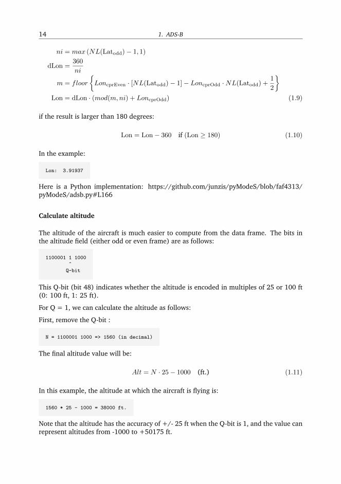
Calculate altitude
The altitude of the aircraft is much easier to compute from the data frame. The bits inthe altitude field (either odd or even frame) are as follows:
1100001 1 1000
^
Q-bit
This Q-bit (bit 48) indicates whether the altitude is encoded in multiples of 25 or 100 ft(0: 100 ft, 1: 25 ft).
For Q = 1, we can calculate the altitude as follows:
First, remove the Q-bit :
N = 1100001 1000 => 1560 (in decimal)
The final altitude value will be:
Alt = N · 25− 1000 (ft.) (1.11)
In this example, the altitude at which the aircraft is flying is:
1560 * 25 - 1000 = 38000 ft.
Note that the altitude has the accuracy of +/- 25 ft when the Q-bit is 1, and the value canrepresent altitudes from -1000 to +50175 ft.

1.4. Airborne Positions 15
The final position
Finally, we have all three components (latitude/longitude/altitude) of the aircraft posi-tion:
LAT: 52.25720 (degrees N)
LON: 3.91937 (degrees E)
ALT: 38000 ft
1.4.2. Locally unambiguous position (decoding with one message)
This method gives the possibility of decoding aircraft using only one message knowing areference position. This method computes the latitude index (j) and the longitude index(m) based on such reference, and can be used with either type of the messages.
The reference position
The reference position should be close to the actual position (eg. position of aircraftpreviously decoded, or the location of ADS-B antenna), and must be within a 180 NMrange.
Calculate dLat
dLat =
{360
4·NZ = 36060 if even message
3604·NZ−1 = 360
59 if odd message(1.12)
Calculate the latitude indexj
j = floor
(LatrefdLat
)+ floor
(mod(Latref , dLat)
dLat− Latcpr +
1
2
)(1.13)
Calculate latitude
Lat = dLat · (j + Latcpr) (1.14)
Calculate dLon
dLon =
{360
NL(Lat) if NL(Lat) > 0
360 if NL(Lat) = 0(1.15)

16 1. ADS-B
Calculate longitude index m
m = floor
(LonrefdLon
)+ floor
(mod(Lonref ,dLon)
dLon− Loncpr +
1
2
)(1.16)
Calculate longitude
Lon = dLon · (m+ Loncpr) (1.17)
Example
For the same example message:
8D40621D58C382D690C8AC2863A7
Reference position:
LAT: 52.258
LON: 3.918
The structure of the message is:
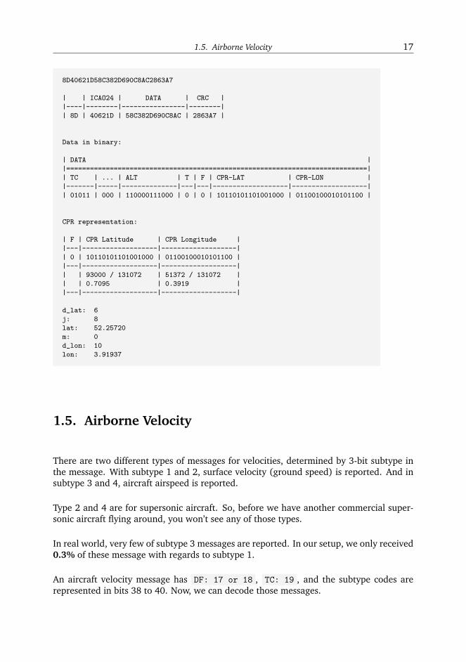
1.5. Airborne Velocity 17
8D40621D58C382D690C8AC2863A7
| | ICAO24 | DATA | CRC |
|----|--------|----------------|--------|
| 8D | 40621D | 58C382D690C8AC | 2863A7 |
Data in binary:
| DATA |
|============================================================================|
| TC | ... | ALT | T | F | CPR-LAT | CPR-LON |
|-------|-----|--------------|---|---|-------------------|-------------------|
| 01011 | 000 | 110000111000 | 0 | 0 | 10110101101001000 | 01100100010101100 |
CPR representation:
| F | CPR Latitude | CPR Longitude |
|---|-------------------|-------------------|
| 0 | 10110101101001000 | 01100100010101100 |
|---|-------------------|-------------------|
| | 93000 / 131072 | 51372 / 131072 |
| | 0.7095 | 0.3919 |
|---|-------------------|-------------------|
d_lat: 6
j: 8
lat: 52.25720
m: 0
d_lon: 10
lon: 3.91937
1.5. Airborne Velocity
There are two different types of messages for velocities, determined by 3-bit subtype inthe message. With subtype 1 and 2, surface velocity (ground speed) is reported. And insubtype 3 and 4, aircraft airspeed is reported.
Type 2 and 4 are for supersonic aircraft. So, before we have another commercial super-sonic aircraft flying around, you won’t see any of those types.
In real world, very few of subtype 3 messages are reported. In our setup, we only received0.3% of these message with regards to subtype 1.
An aircraft velocity message has DF: 17 or 18 , TC: 19 , and the subtype codes arerepresented in bits 38 to 40. Now, we can decode those messages.

18 1. ADS-B
1.5.1. Subtype 1 (Ground Speed)
Subtype 1 (subsonic, ground speed), are broadcast when ground velocity information isavailable. The aircraft velocity contains speed and heading information. The speed andheading are also decomposed into North-South, and East-West components.
For example, the following message is received:
Message: 8D485020994409940838175B284F
| | ICAO24 | DATA | CRC |
|----|--------|----------------|--------|
| 8D | 485020 | 99440994083817 | 5B284F |
Convert DATA [99440994083817] into binary:
|-------|-----|----|--------|-----|------|------------|
| TC | ST | IC | RESV_A | NAC | S-EW | V-EW |
|-------|-----|----|--------|-----|------|------------|
| 10011 | 001 | 0 | 1 | 000 | 1 | 0000001001 |
|------|------------|-------|------|-----------|--------|-------|---------|
| S-NS | V-NS | VrSrc | S-Vr | Vr | RESV_B | S_Dif | Dif |
|------|------------|-------|------|-----------|--------|-------|---------|
| 1 | 0010100000 | 0 | 1 | 000001110 | 00 | 0 | 0010111 |
There are quite a few parameters in the velocity message. From left to right, the numberof bits indicates the contents in following Table 1.4
Table 1.4. Airborne velocity message bits explained - Subtype 1
MSG Bits Data Bits Len Abbr Content
33 - 37 1 - 5 5 TC Type code38 - 40 6 - 8 3 ST Subtype41 9 1 IC Intent change flag42 10 1 RESV A Reserved-A43 - 45 11 - 13 3 NAC Velocity uncertainty (NAC)46 14 1 S ew East-West velocity sign47 - 56 15 - 24 10 V ew East-West velocity57 25 1 S ns North-South velocity sign58 - 67 26 - 35 10 V ns North-South velocity68 36 1 VrSrc Vertical rate source69 37 1 S vr Vertical rate sign70 - 78 38 - 46 9 Vr Vertical rate79 - 80 47 - 48 2 RESV B Reserved-B81 49 1 S Dif Diff from baro alt, sign82 - 88 50 - 66 7 Dif Diff from baro alt
1.5. Airborne Velocity 19
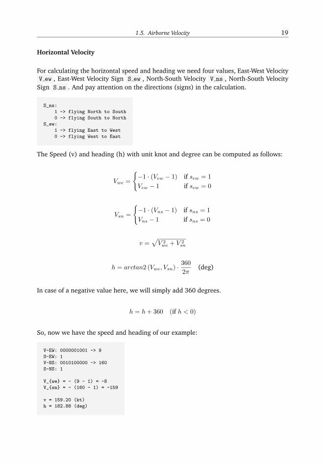
Horizontal Velocity
For calculating the horizontal speed and heading we need four values, East-West VelocityV ew , East-West Velocity Sign S ew , North-South Velocity V ns , North-South Velocity
Sign S ns . And pay attention on the directions (signs) in the calculation.
S_ns:
1 -> flying North to South
0 -> flying South to North
S_ew:
1 -> flying East to West
0 -> flying West to East
The Speed (v) and heading (h) with unit knot and degree can be computed as follows:
Vwe =
{−1 · (Vew − 1) if sew = 1
Vew − 1 if sew = 0
Vsn =
{−1 · (Vns − 1) if sns = 1
Vns − 1 if sns = 0
v =√V 2we + V 2
sn
h = arctan2 (Vwe, Vsn) ·360
2π(deg)
In case of a negative value here, we will simply add 360 degrees.
h = h+ 360 (if h < 0)
So, now we have the speed and heading of our example:
V-EW: 0000001001 -> 9
S-EW: 1
V-NS: 0010100000 -> 160
S-NS: 1
V_{we} = - (9 - 1) = -8
V_{sn} = - (160 - 1) = -159
v = 159.20 (kt)
h = 182.88 (deg)
20 1. ADS-B
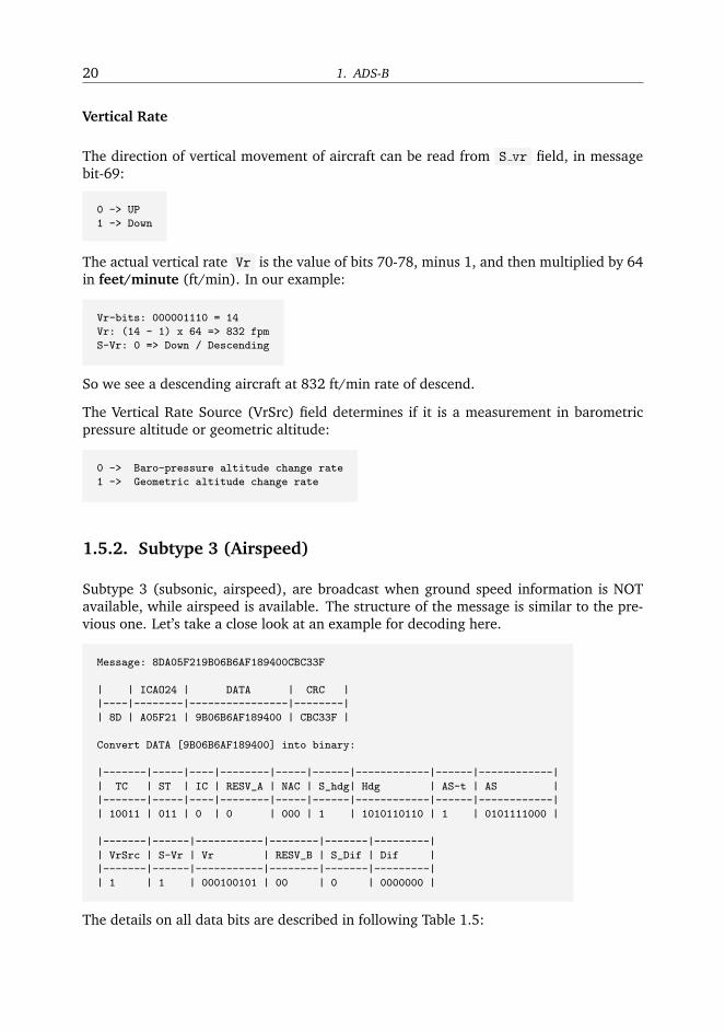
Vertical Rate
The direction of vertical movement of aircraft can be read from S vr field, in messagebit-69:
0 -> UP
1 -> Down
The actual vertical rate Vr is the value of bits 70-78, minus 1, and then multiplied by 64in feet/minute (ft/min). In our example:
Vr-bits: 000001110 = 14
Vr: (14 - 1) x 64 => 832 fpm
S-Vr: 0 => Down / Descending
So we see a descending aircraft at 832 ft/min rate of descend.
The Vertical Rate Source (VrSrc) field determines if it is a measurement in barometricpressure altitude or geometric altitude:
0 -> Baro-pressure altitude change rate
1 -> Geometric altitude change rate
1.5.2. Subtype 3 (Airspeed)
Subtype 3 (subsonic, airspeed), are broadcast when ground speed information is NOTavailable, while airspeed is available. The structure of the message is similar to the pre-vious one. Let’s take a close look at an example for decoding here.
Message: 8DA05F219B06B6AF189400CBC33F
| | ICAO24 | DATA | CRC |
|----|--------|----------------|--------|
| 8D | A05F21 | 9B06B6AF189400 | CBC33F |
Convert DATA [9B06B6AF189400] into binary:
|-------|-----|----|--------|-----|------|------------|------|------------|
| TC | ST | IC | RESV_A | NAC | S_hdg| Hdg | AS-t | AS |
|-------|-----|----|--------|-----|------|------------|------|------------|
| 10011 | 011 | 0 | 0 | 000 | 1 | 1010110110 | 1 | 0101111000 |
|-------|------|-----------|--------|-------|---------|
| VrSrc | S-Vr | Vr | RESV_B | S_Dif | Dif |
|-------|------|-----------|--------|-------|---------|
| 1 | 1 | 000100101 | 00 | 0 | 0000000 |
The details on all data bits are described in following Table 1.5:

1.5. Airborne Velocity 21
Table 1.5. Airborne velocity message bits explained - Subtype 3
MSG Bits DATA Bits Len Abbr Content
33 - 37 1 - 5 5 TC Type code38 - 40 6 - 8 3 ST Subtype41 9 1 IC Intent change flag42 10 1 RESV A Reserved-A43 - 45 11 - 13 3 NAC Velocity uncertainty (NAC)46 14 1 S hdg Heading status47 - 56 15 - 24 10 Hdg Heading (proportion)57 25 1 AS-t Airspeed Type58 - 67 26 - 35 10 AS Airspeed68 36 1 VrSrc Vertical rate source69 37 1 S vr Vertical rate sign70 - 78 38 - 46 9 Vr Vertical rate79 - 80 47 - 48 2 RESV B Reserved-B81 49 1 S Dif Difference from baro alt, sign82 - 88 50 - 66 7 Dif Difference from baro alt
Heading
S hdg makes the status of heading data:
0 -> heading data not available
1 -> heading data available
10-bits Hdg is the represent the proportion of the degrees of a full circle, i.e. 360 degrees.(Note: 0000000000 - 1111111111 represents 0 - 1023 )
heading = Decimal(Hdg)/1024 ∗ 360o
in our example :
1010110110 -> 694
heading = 694 / 1024 * 360 = 243.98 (degree)
Velocity (Airspeed)
To find out which type of the airspeed (TAS or IAS), first we need to look at the AS-t
field:
0 -> Indicated Airspeed (IAS)
1 -> True Airspeed (TAS)

22 1. ADS-B
And then the speed is simply a binary to decimal conversion of AS bits (in knot). In ourexample:
0101111000 -> 376 knot
Vertical Rate
The vertical rate decoding remains the same as subtype 1.

Chapter 2
Advanced ADS-B topics
In this chapter, we are going to discuss some advanced topics regarding ADS-B. Ratherthan position and velocity of aircraft, ADS-B provides many other types of interestinginformation. Especially with newer versions of the ADS-B implementations (yes, there ismore than one version!), more data is downlinked. We will start with an introductionon different ADS-B versions and differences among them. Then, go on with the decodingwith some new message types. Lastly, the uncertainty of ADS-B measurements will bediscussed in detail.
2.1. ADS-B versions
In this advanced chapter, we are going to looking into different versions and evolution ofthe ADS-B.
Since the beginning of ADS-B, there have been three different versions (to my knowledge)implemented. The major reason for these updates is to enable more information (typesof data) in ADS-B. Documentations on these versions and differences are quite far fromuser friendly. They are always presented in a very scattered fashion. Even the officialICAO 9871 document is confusing to read. I am going to try my best to put the pieces
together in this chapter.
There are three versions implemented so far, starting from Version 0, then Version 1around 2008 and Version 2 around 2012. Major changes in Version 1 and Version 2 arelisted as follows:
From Version 0 to Version 1 :
• Added Type Code 28, 19, and 31 messages
– TC=28 : Aircraft status - Emergency/priority status and ACAS RA Broadcast
– TC=29 : Target state and status
– TC=31 : Operational status
• Introduced the “Navigation integrity category ( NIC )” and “Surveillance integritylevel ( SIL )” in addition to the “Navigation accuracy category ( NAC )” from theVersion 0
– Type Code and an NIC Supplement bit ( NICs ) is used to define the NIC

24 2. Advanced ADS-B topics
– NIC Supplement bit included in TC=31 messages
• The ADS-B version number is now indicated in operation status message TC=31
From Version 1 to Version 2 :
• Re-defined the structure and content of TC=28 , TC=29 , and TC=31 messages.
• Introduced two additional NIC Supplement Bit
• NICa is defined in operational status messages ( TC=31 )
• NICb is defined in airborne position messages ( TC=9-18 )
• NICc is defined in operational status messages ( TC=31 )
• Introduced an additional “Horizontal Containment Radius ( Rc )” within NIC=6 /TC=13
2.1.1. Identify the ADS-B Version
There are two steps to check the ADS-B version, this is due to the fact that ADS-BVersion 0 is not included in any message.
1. Step 1: Check whether an aircraft is broadcasting ADS-B messages with TC=31 atall. If no message is ever reported, it is safe to assume that the version is Version 0
2. Step 2: If messages with TC=31 are received, check the version numbers located inthe 41-43 bit of the payload (or 73-75 bit of the message).
After identifying the right ADS-B version for an aircraft (which does not change often),one can decode related TC=28 , TC=29 , and TC=31 messages accordingly.
2.2. Aircraft Operation Status
Operation status message is introduced since the Version 1 of ADS-B. And there arealso slight differences in the structure of Aircraft Operation Messages between Version 1and 2.
To understand about these versions, first take a look at the ADS-B versionchapter.
The operation status is transmitted with Type Code 31 ( TC=31 ). The structure of the
message (in Version 1 ) is laid out as follows:

2.2. Aircraft Operation Status 25
+----------------------------------------+------+------+------+
| FIELD | MSG | MB |N-BITS|
+========================================+======+======+======+
| Downlink Format = 17 | 1 | | 8 |
| | 8 | | |
+----------------------------------------+------+------+------+
| ICAO Address | 9 | | 24 |
| | 32 | | |
+----------------------------------------+------+------+------+
| Type Code = 31 | 33 | 1 | 5 |
| | 37 | 5 | |
+----------------------------------------+------+------+------+
| Subtype Code | 38 | 6 | 3 |
| | | | |
| - 0: airborne | | | |
| - 1: surface | | | |
| - 2-7: reserved | 40 | 8 | |
+-------------------+--------------------+------+------+------+
| | | 41 | 9 | 16 |
| Airborne | Surface | | | |
| capacity class | capacity class | | | |
| codes | codes | | | |
| | | 52 | 20 | |
| +--------------------+------+------+------+
| | | 53 | 21 | (4) |
| | Length/width | | | |
| | codes | | | |
| | | 56 | 24 | |
+-------------------+--------------------+------+------+------+
| Operational mode code | 57 | 25 | 16 |
| | | | |
| | | | |
| | 72 | 40 | |
+----------------------------------------+------+------+------+
| ADS-B version number | 73 | 41 | 3 |
| | 75 | 43 | |
+----------------------------------------+------+------+------+
| NIC supplement bit | 76 | 44 | 1 |
+----------------------------------------+------+------+------+
| NACp: Navigation accuracy category | 77 | 45 | 4 |
| - position | 80 | 48 | |
+-------------------+--------------------+------+------+------+
| BAQ = 0 | Reserved | 81 | 49 | 2 |
| | | 82 | 50 | |
+-------------------+--------------------+------+------+------+
| SIL: Surveillance integrity level | 83 | 51 | 2 |
| | 84 | 52 | |
+-------------------+--------------------+------+------+------+
| NIC-BARO | TRK/HDG | 85 | 53 | 1 |
+-------------------+--------------------+------+------+------+
| HRD | 86 | 54 | 1 |
+----------------------------------------+------+------+------+
| Reserved | 87 | 55 | 2 |
| | 88 | 56 | |
+----------------------------------------+------+------+------+
Acronyms:

26 2. Advanced ADS-B topics
• BAQ: Barometric Altitude Quality (always set to zero for airborne messagesubtype=1 )
• HRD: Horizontal Reference Direction
– 0: True North
– 1: Magnetic North
In ADS-B Version 2 , most part of the message remains the same, we will only addressthe second half of the message, where the changes have been made.
+----------------------------------------+------+------+------+
| FIELD | MSG | MB |N-BITS|
+========================================+======+======+======+
| Airborne | Surface | 57 | 25 | 16 |
| operational | operational | | | |
| mode code | mode code | | | |
| | | 72 | 40 | |
+-------------------+--------------------+------+------+------+
| ADS-B version number | 73 | 41 | 3 |
| | 75 | 43 | |
+----------------------------------------+------+------+------+
| NIC supplement bit - A | 76 | 44 | 1 |
+----------------------------------------+------+------+------+
| NACp: Navigation accuracy category | 77 | 45 | 4 |
| - position | | | |
| | 80 | 48 | |
+-------------------+--------------------+------+------+------+
| GVA | Reserved | 81 | 49 | 2 |
| | | 82 | 50 | |
+-------------------+--------------------+------+------+------+
| SIL: Surveillance integrity level | 83 | 51 | 2 |
| | 84 | 52 | |
+-------------------+--------------------+------+------+------+
| NIC-BARO | TRK/HDG | 85 | 53 | 1 |
+-------------------+--------------------+------+------+------+
| HRD | 86 | 54 | 1 |
+----------------------------------------+------+------+------+
| SIL supplement bit | 87 | 55 | 1 |
+----------------------------------------+------+------+------+
| Reserved | 88 | 56 | 1 |
+----------------------------------------+------+------+------+
Acronyms:
• GVA: Geometric Vertical Accuracy - GNSS position source, 95% vertical figure ofmerit ( VFOM )
– 0: unknown or > 150 meters
– 1: < 150 meters
– 2: < 45 meters
– 3: reserved
• SIL, NIC, NAC are also related to measurement uncertainty or accuracy.

2.3. Uncertainty and accuracy 27
– A lot or more details are given in the uncertainty chapter.
2.3. Uncertainty and accuracy
NIC, NAC, NUC, and SIL, those acronyms do sound confusing. They are categorical num-bers for the integrity, accuracy, or uncertainties of the position measurements.
• NUCp : Navigation Uncertainty Category - Position
– Values: 0 - 9
– Version 0, 1, and 2
• NUCr : Navigation Uncertainty Category - Velocity (Rate)
– Values: 0 - 4
– Version 0
• NIC : Navigation Integrity Category
– Values: 0 - 11
– Version 1 and 2
• NACp : Navigation Accuracy Category - Position
– Values: 0 - 11
– Version 1 and 2
• NACv : Navigation Accuracy Category - Velocity
– Values: 0 - 4
– Version 1 and 2
• SIL : Surveillance Integrity Level
– Values: 0 - 3
– Version 1 and 2
For each category name, specific values are given corresponding to the numerical indica-tors. The relation of the category names and value names are:
• NUCp :
– Horizontal Protection Limit ( HPL )
– 95% Containment Radius - Horizontal ( RCu )
– 95% Containment Radius - Vertical ( RCv )
• NUCr :
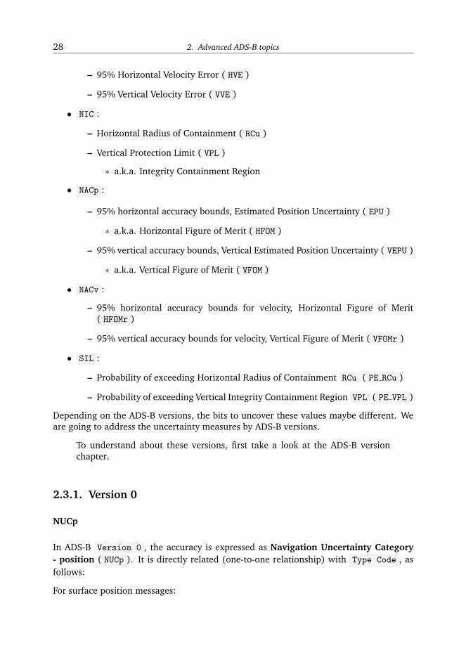
28 2. Advanced ADS-B topics
– 95% Horizontal Velocity Error ( HVE )
– 95% Vertical Velocity Error ( VVE )
• NIC :
– Horizontal Radius of Containment ( RCu )
– Vertical Protection Limit ( VPL )
∗ a.k.a. Integrity Containment Region
• NACp :
– 95% horizontal accuracy bounds, Estimated Position Uncertainty ( EPU )
∗ a.k.a. Horizontal Figure of Merit ( HFOM )
– 95% vertical accuracy bounds, Vertical Estimated Position Uncertainty ( VEPU )
∗ a.k.a. Vertical Figure of Merit ( VFOM )
• NACv :
– 95% horizontal accuracy bounds for velocity, Horizontal Figure of Merit( HFOMr )
– 95% vertical accuracy bounds for velocity, Vertical Figure of Merit ( VFOMr )
• SIL :
– Probability of exceeding Horizontal Radius of Containment RCu ( PE RCu )
– Probability of exceeding Vertical Integrity Containment Region VPL ( PE VPL )
Depending on the ADS-B versions, the bits to uncover these values maybe different. Weare going to address the uncertainty measures by ADS-B versions.
To understand about these versions, first take a look at the ADS-B versionchapter.
2.3.1. Version 0
NUCp
In ADS-B Version 0 , the accuracy is expressed as Navigation Uncertainty Category- position ( NUCp ). It is directly related (one-to-one relationship) with Type Code , asfollows:
For surface position messages:

2.3. Uncertainty and accuracy 29
+------+---+----+----+----+---+
| TC | 0 | 5 | 6 | 7 | 8 |
+------+---+----+----+----+---+
| NUCp | 0 | 9 | 8 | 7 | 6 |
+------+---+----+----+----+---+
For airborne position with barometric altitude:
+------+---+----+----+----+----+----+----+----+----+----+
| TC | 9 | 10 | 11 | 12 | 13 | 14 | 15 | 16 | 17 | 18 |
+------+---+----+----+----+----+----+----+----+----+----+
| NUCp | 9 | 8 | 7 | 6 | 5 | 4 | 3 | 2 | 1 | 0 |
+------+---+----+----+----+----+----+----+----+----+----+
For airborne position with GNSS altitude:
+------+------+------+-----+
| TC | 20 | 21 | 22 |
+------+------+------+-----+
| NUCp | 9 | 8 | 0 |
+------+------+------+-----+
Higher number of NUCp represents a higher confidence of in the position measurement(hence, a lower uncertainty). Horizontal Protection Limit ( HPL ) and Radius of contain-ment for horizontal ( RCu ) are used to quantify the uncertainty.
For surface position ( TC=5-8 ):
+----+------+--------------------+---------------------+
| TC | NUCp | HPL | RCu |
+====+======+====================+=====================+
| 5 | 9 | < 7.5 m | < 3 m |
+----+------+--------------------+---------------------+
| 6 | 8 | < 25 m | < 10 m |
+----+------+--------------------+---------------------+
| 7 | 7 | < 0.1 NM (185 m) | < 0.05 NM (93 m) |
+----+------+--------------------+---------------------+
| 8 | 6 | > 0.1 NM (185 m) | > 0.05 NM (93 m) |
+----+------+--------------------+---------------------+
For airborne position with barometric altitude ( TC=9-18 ):

30 2. Advanced ADS-B topics
+------+------+--------------------+---------------------+
| TC | NUCp | HPL | RCu |
+======+======+====================+=====================+
| 9 | 9 | < 7.5 m | < 3 m |
+------+------+--------------------+---------------------+
| 10 | 8 | < 25 m | < 10 m |
+------+------+--------------------+---------------------+
| 11 | 7 | < 0.1 NM (185 m) | < 0.05 NM (93 m) |
+------+------+--------------------+---------------------+
| 12 | 6 | < 0.2 NM (370 m) | < 0.1 NM (185 m) |
+------+------+--------------------+---------------------+
| 13 | 5 | < 0.5 NM (926 m) | < 0.25 NM (463 m) |
+------+------+--------------------+---------------------+
| 14 | 4 | < 1 NM (1852 m) | < 0.5 NM (926 m) |
+------+------+--------------------+---------------------+
| 15 | 3 | < 2 NM (3704 m) | < 1 NM (1852 m) |
+------+------+--------------------+---------------------+
| 16 | 2 | < 10 NM (18520 m) | < 5 NM (9260 m) |
+------+------+--------------------+---------------------+
| 17 | 1 | < 20 NM (37040 m) | < 10 NM (18520 m) |
+------+------+--------------------+---------------------+
| 18 | 0 | > 20 NM (37040 m) | > 10 NM (18520 m) |
+------+------+--------------------+---------------------+
In the case of airborne position with GNSS height ( TC=20-22 ), HPL and RCu are de-fined slight differently. In addition, Radius of containment for vertical position ( RCv ) isadded:
+------+------+----------+---------+---------+
| TC | NUCp | HPL | RCu | RCv |
+======+======+==========+=========+=========+
| 20 | 9 | < 7.5 m | < 3 m | < 4 m |
+------+------+----------+---------+---------+
| 21 | 8 | < 25 m | < 10 m | < 15 m |
+------+------+----------+---------+---------+
| 22 | 0 | > 25 m | > 10 m | > 15 m |
+------+------+----------+---------+---------+
NUCv
The Navigation Uncertainty Category - velocity ( NUCv ) it is used to indicate the un-certainty of the horizontal and vertical speeds. Related bits are located at the airbornevelocity message, TC=19 , message bit 43-45 (or payload bit 11-13). It defines the 95%of the error in horizontal and vertical speed.

2.3. Uncertainty and accuracy 31
+------+-------------+------------------------+
| NUCp | HVE (95%) | VVE (95%) |
+======+=============+========================+
| 0 | unknown | unknown |
+------+-------------+------------------------+
| 1 | < 10 m/s | < 15.2 m/s (50 pfs) |
+------+-------------+------------------------+
| 2 | < 3 m/s | < 4.5 m/s (15 fps) |
+------+-------------+------------------------+
| 3 | < 1 m/s | < 1.5 m/s (5 fps) |
+------+-------------+------------------------+
| 4 | < 0.3 m/s | < 0.46 m/s (1.5 fps) |
+------+-------------+------------------------+
2.3.2. Version 1
NIC
In ADS-B Version 1, Navigation Integrity Category ( NIC ) is introduced to provide morelevels of uncertainty definitions. The NUCp value is still kept, but has been moved to the
new “operation status messages” ( TC=31 ).
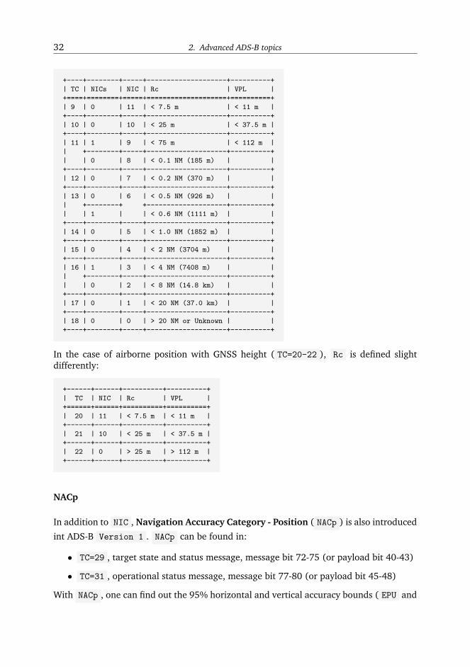
As for NIC , in Type Code : 7 and 11 , two NIC levels present in each code. In order
to distinguish these two different levels, a NIC Supplement Bit ( NICs ) is introduced in“operation status messages” TC=31 (message bit 76 or payload bit 44). The relation ofTC, NIC, and Rc are list in following tables.
For surface position ( TC=5-8 )
+------+--------+-------+-----------------------+
| TC | NICs | NIC | Rc |
+======+========+=======+=======================+
| 5 | 0 | 11 | < 7.5 m |
+------+--------+-------+-----------------------+
| 6 | 0 | 10 | < 25 m |
+------+--------+-------+-----------------------+
| 7 | 1 | 9 | < 75 m |
| +--------+-------+-----------------------+
| | 0 | 8 | < 0.1 NM (185 m) |
+------+--------+-------+-----------------------+
| 8 | 0 | 0 | > 0.1 NM or Unknown |
+------+--------+-------+-----------------------+
For airborne position with barometric altitude ( TC=9-18 ):
32 2. Advanced ADS-B topics
+----+--------+-----+--------------------+----------+
| TC | NICs | NIC | Rc | VPL |
+====+========+=====+====================+==========+
| 9 | 0 | 11 | < 7.5 m | < 11 m |
+----+--------+-----+--------------------+----------+
| 10 | 0 | 10 | < 25 m | < 37.5 m |
+----+--------+-----+--------------------+----------+
| 11 | 1 | 9 | < 75 m | < 112 m |
| +--------+-----+--------------------+----------+
| | 0 | 8 | < 0.1 NM (185 m) | |
+----+--------+-----+--------------------+----------+
| 12 | 0 | 7 | < 0.2 NM (370 m) | |
+----+--------+-----+--------------------+----------+
| 13 | 0 | 6 | < 0.5 NM (926 m) | |
| +--------+ +--------------------+----------+
| | 1 | | < 0.6 NM (1111 m) | |
+----+--------+-----+--------------------+----------+
| 14 | 0 | 5 | < 1.0 NM (1852 m) | |
+----+--------+-----+--------------------+----------+
| 15 | 0 | 4 | < 2 NM (3704 m) | |
+----+--------+-----+--------------------+----------+
| 16 | 1 | 3 | < 4 NM (7408 m) | |
| +--------+-----+--------------------+----------+
| | 0 | 2 | < 8 NM (14.8 km) | |
+----+--------+-----+--------------------+----------+
| 17 | 0 | 1 | < 20 NM (37.0 km) | |
+----+--------+-----+--------------------+----------+
| 18 | 0 | 0 | > 20 NM or Unknown | |
+----+--------+-----+--------------------+----------+
In the case of airborne position with GNSS height ( TC=20-22 ), Rc is defined slightdifferently:
+------+------+----------+----------+
| TC | NIC | Rc | VPL |
+======+======+==========+==========+
| 20 | 11 | < 7.5 m | < 11 m |
+------+------+----------+----------+
| 21 | 10 | < 25 m | < 37.5 m |
+------+------+----------+----------+
| 22 | 0 | > 25 m | > 112 m |
+------+------+----------+----------+
NACp
In addition to NIC , Navigation Accuracy Category - Position ( NACp ) is also introduced
int ADS-B Version 1 . NACp can be found in:
• TC=29 , target state and status message, message bit 72-75 (or payload bit 40-43)
• TC=31 , operational status message, message bit 77-80 (or payload bit 45-48)
With NACp , one can find out the 95% horizontal and vertical accuracy bounds ( EPU and
2.3. Uncertainty and accuracy 33
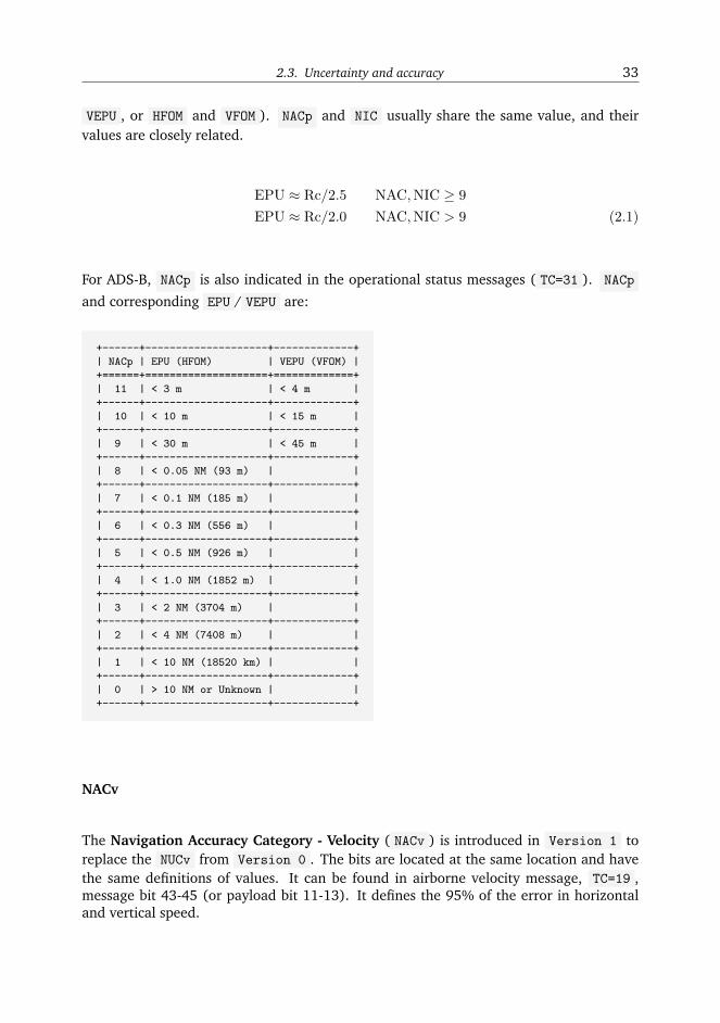
VEPU , or HFOM and VFOM ). NACp and NIC usually share the same value, and theirvalues are closely related.
EPU ≈ Rc/2.5 NAC,NIC ≥ 9
EPU ≈ Rc/2.0 NAC,NIC > 9 (2.1)
For ADS-B, NACp is also indicated in the operational status messages ( TC=31 ). NACp
and corresponding EPU / VEPU are:
+------+--------------------+-------------+
| NACp | EPU (HFOM) | VEPU (VFOM) |
+======+====================+=============+
| 11 | < 3 m | < 4 m |
+------+--------------------+-------------+
| 10 | < 10 m | < 15 m |
+------+--------------------+-------------+
| 9 | < 30 m | < 45 m |
+------+--------------------+-------------+
| 8 | < 0.05 NM (93 m) | |
+------+--------------------+-------------+
| 7 | < 0.1 NM (185 m) | |
+------+--------------------+-------------+
| 6 | < 0.3 NM (556 m) | |
+------+--------------------+-------------+
| 5 | < 0.5 NM (926 m) | |
+------+--------------------+-------------+
| 4 | < 1.0 NM (1852 m) | |
+------+--------------------+-------------+
| 3 | < 2 NM (3704 m) | |
+------+--------------------+-------------+
| 2 | < 4 NM (7408 m) | |
+------+--------------------+-------------+
| 1 | < 10 NM (18520 km) | |
+------+--------------------+-------------+
| 0 | > 10 NM or Unknown | |
+------+--------------------+-------------+
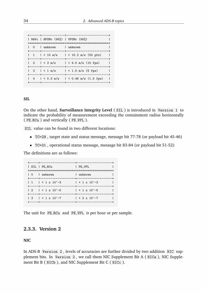
NACv
The Navigation Accuracy Category - Velocity ( NACv ) is introduced in Version 1 toreplace the NUCv from Version 0 . The bits are located at the same location and havethe same definitions of values. It can be found in airborne velocity message, TC=19 ,message bit 43-45 (or payload bit 11-13). It defines the 95% of the error in horizontaland vertical speed.
34 2. Advanced ADS-B topics
+------+-------------+------------------------+
| NAVc | HFOMr (95%) | VFOMr (95%) |
+======+=============+========================+
| 0 | unknown | unknown |
+------+-------------+------------------------+
| 1 | < 10 m/s | < 15.2 m/s (50 pfs) |
+------+-------------+------------------------+
| 2 | < 3 m/s | < 4.5 m/s (15 fps) |
+------+-------------+------------------------+
| 3 | < 1 m/s | < 1.5 m/s (5 fps) |
+------+-------------+------------------------+
| 4 | < 0.3 m/s | < 0.46 m/s (1.5 fps) |
+------+-------------+------------------------+
SIL
On the other hand, Surveillance Integrity Level ( SIL ) is introduced in Version 1 toindicate the probability of measurement exceeding the containment radius horizontally( PE RCu ) and vertically ( PE VPL ).
SIL value can be found in two different locations:
• TC=29 , target state and status message, message bit 77-78 (or payload bit 45-46)
• TC=31 , operational status message, message bit 83-84 (or payload bit 51-52)
The definitions are as follows:
+-----+--------------------+--------------------+
| SIL | PE_RCu | PE_VPL |
+=====+====================+====================+
| 0 | unknown | unknown |
+-----+--------------------+--------------------+
| 1 | < 1 x 10^-3 | < 1 x 10^-3 |
+-----+--------------------+--------------------+
| 2 | < 1 x 10^-5 | < 1 x 10^-5 |
+-----+--------------------+--------------------+
| 3 | < 1 x 10^-7 | < 2 x 10^-7 |
+-----+--------------------+--------------------+
The unit for PE RCu and PE VPL is per hour or per sample.
2.3.3. Version 2
NIC
In ADS-B Version 2 , levels of accuracies are further divided by two addition NIC sup-plement bits. In Version 2 , we call them NIC Supplement Bit A ( NICa ), NIC Supple-ment Bit B ( NICb ), and NIC Supplement Bit C ( NICc ).
2.3. Uncertainty and accuracy 35
• NICa is in the same location as in ADS-B Version 1 , which is located in theoperational status message TC=31 (message bit 76 or payload bit 44).
• NICb is located in the airborne position message ( TC=9-18 , message bit 40 orpayload bit 8), where the “single antenna flag” was located in previous ADS-B ver-sions.
• NICc is also located in the operational status message TC=31 (message bit 52 orpayload bit 20).
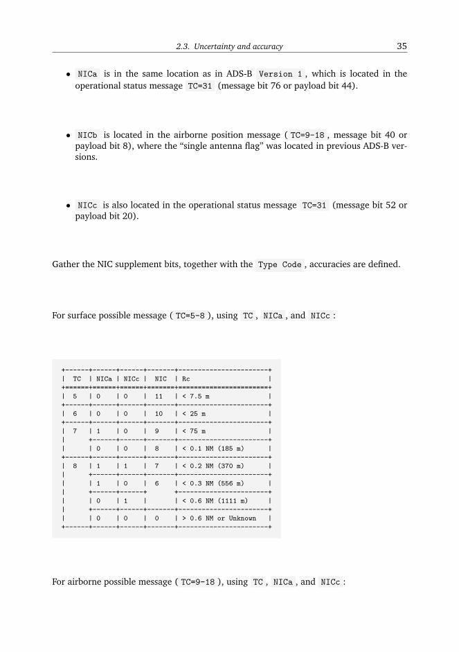
Gather the NIC supplement bits, together with the Type Code , accuracies are defined.
For surface possible message ( TC=5-8 ), using TC , NICa , and NICc :
+------+------+------+-------+-----------------------+
| TC | NICa | NICc | NIC | Rc |
+======+======+======+=======+=======================+
| 5 | 0 | 0 | 11 | < 7.5 m |
+------+------+------+-------+-----------------------+
| 6 | 0 | 0 | 10 | < 25 m |
+------+------+------+-------+-----------------------+
| 7 | 1 | 0 | 9 | < 75 m |
| +------+------+-------+-----------------------+
| | 0 | 0 | 8 | < 0.1 NM (185 m) |
+------+------+------+-------+-----------------------+
| 8 | 1 | 1 | 7 | < 0.2 NM (370 m) |
| +------+------+-------+-----------------------+
| | 1 | 0 | 6 | < 0.3 NM (556 m) |
| +------+------+ +-----------------------+
| | 0 | 1 | | < 0.6 NM (1111 m) |
| +------+------+-------+-----------------------+
| | 0 | 0 | 0 | > 0.6 NM or Unknown |
+------+------+------+-------+-----------------------+
For airborne possible message ( TC=9-18 ), using TC , NICa , and NICc :

36 2. Advanced ADS-B topics
+----+------+------+-----+-----------------------+
| TC | NICa | NICb | NIC | Rc |
+====+======+======+=====+=======================+
| 9 | 0 | 0 | 11 | < 7.5 m |
+----+------+------+-----+-----------------------+
| 10 | 0 | 0 | 10 | < 25 m |
+----+------+------+-----+-----------------------+
| 11 | 1 | 1 | 9 | < 75 m |
| +------+------+-----+-----------------------+
| | 0 | 0 | 8 | < 0.1 NM (185 m) |
+----+------+------+-----+-----------------------+
| 12 | 0 | 0 | 7 | < 0.2 NM (370 m) |
+----+------+------+-----+-----------------------+
| 13 | 0 | 1 | 6 | < 0.3 NM (556 m) |
| +------+------+ +-----------------------+
| | 0 | 0 | | < 0.5 NM (926 m) |
| +------+------+ +-----------------------+
| | 1 | 1 | | < 0.6 NM (1111 m) |
+----+------+------+-----+-----------------------+
| 14 | 0 | 0 | 5 | < 1.0 NM (1852 m) |
+----+------+------+-----+-----------------------+
| 15 | 0 | 0 | 4 | < 2 NM (3704 m) |
+----+------+------+-----+-----------------------+
| 16 | 1 | 1 | 3 | < 4 NM (7408 m) |
| +------+------+-----+-----------------------+
| | 0 | 0 | 2 | < 8 NM (14.8 km) |
+----+------+------+-----+-----------------------+
| 17 | 0 | 0 | 1 | < 20 NM (37.0 km) |
+----+------+------+-----+-----------------------+
| 18 | 0 | 0 | 0 | > 20 NM or Unknown |
+----+------+------+-----+-----------------------+
In the case of airborne position with GNSS height ( TC=20-22 ), the table remains thesame as previous version.
+------+------+----------+
| TC | NIC | Rc |
+======+======+==========+
| 20 | 11 | < 7.5 m |
+------+------+----------+
| 21 | 10 | < 25 m |
+------+------+----------+
| 22 | 0 | > 25 m |
+------+------+----------+
NACp
NACp in Version 2 remains the same as in Version 1 .
NACv
NACv in Version 2 remains the same as in Version 1 .
2.3. Uncertainty and accuracy 37
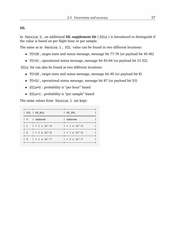
SIL
In Version 2 , an additional SIL supplement bit ( SILs ) is introduced to distinguish ifthe value is based on per flight hour or per sample.
The same as in Version 1 , SIL value can be found in two different locations:
• TC=29 , target state and status message, message bit 77-78 (or payload bit 45-46)
• TC=31 , operational status message, message bit 83-84 (or payload bit 51-52)
SILs bit can also be found at two different locations:
• TC=29 , target state and status message, message bit 40 (or payload bit 8)
• TC=31 , operational status message, message bit 87 (or payload bit 55)
• SILs=0 : probability is “per hour” based
• SILs=1 : probability is “per sample” based
The same values from Version 1 are kept:
+-----+--------------------+--------------------+
| SIL | PE_RCu | PE_VPL |
+=====+====================+====================+
| 0 | unknown | unknown |
+-----+--------------------+--------------------+
| 1 | < 1 x 10^-3 | < 1 x 10^-3 |
+-----+--------------------+--------------------+
| 2 | < 1 x 10^-5 | < 1 x 10^-5 |
+-----+--------------------+--------------------+
| 3 | < 1 x 10^-7 | < 2 x 10^-7 |
+-----+--------------------+--------------------+
Chapter 3
Ehanced Mode-S
The Mode-S Enhanced Surveillance (EHS) provides to Air Traffic Control (ATC) moreinformation than what is included in the Mode-S Elementary Surveillance (ELS).
There are quite a few very interesting data contained within various types of the EHSmessages. Such as: airspeeds (IAS, TAS, Mach), roll angles, track angles, track anglerates, selected altitude, magnetic heading, vertical rate, etc.
There are a few challenges to decode this information:
1. Which aircraft does one message come from?
2. What is the type of one message (aka which BDS code) most likely to be?
3. How reliable is the information that has been decoded?
3.1. Enhanced Mode-S Basics
3.1.1. Downlink Format and message structure
DF 20 and DF 21 are used for downlink messages.
The same as ADS-B, in all Mode-S messages, the first 5 bits contain the Downlink For-mat. The same identification process can be used to discover EHS messages. So the EHSmessages starting bits are:
DF20 - 10100
DF21 - 10101
The message is structured as follows, where the digit represents the number of binarydigits:
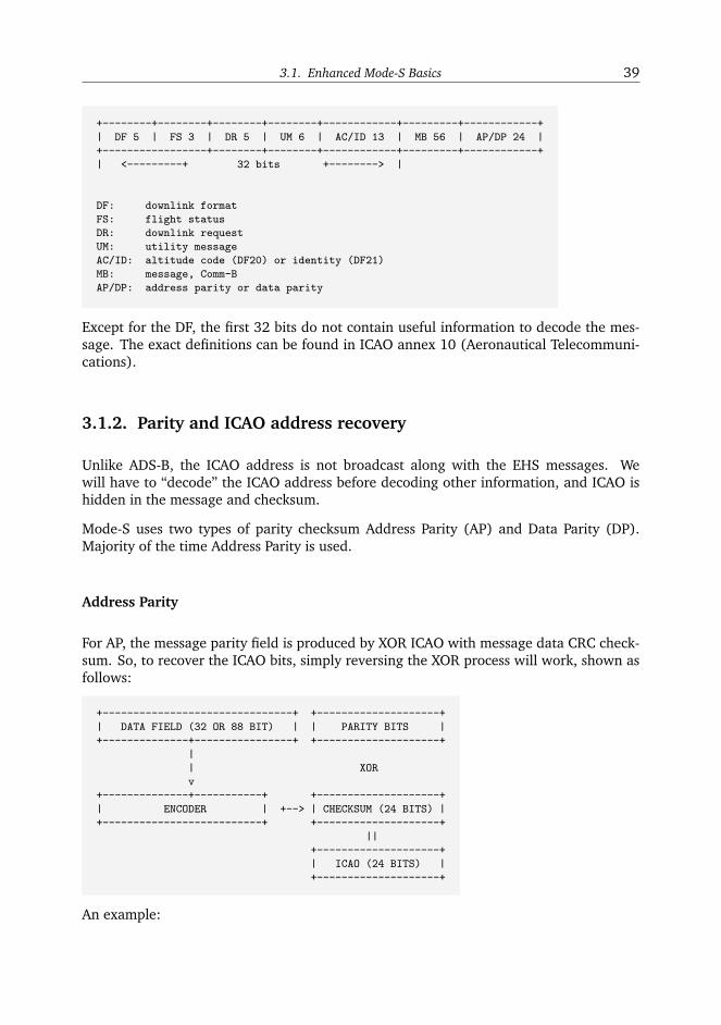
3.1. Enhanced Mode-S Basics 39
+--------+--------+--------+--------+------------+---------+------------+
| DF 5 | FS 3 | DR 5 | UM 6 | AC/ID 13 | MB 56 | AP/DP 24 |
+-----------------+--------+--------+------------+---------+------------+
| <---------+ 32 bits +--------> |
DF: downlink format
FS: flight status
DR: downlink request
UM: utility message
AC/ID: altitude code (DF20) or identity (DF21)
MB: message, Comm-B
AP/DP: address parity or data parity
Except for the DF, the first 32 bits do not contain useful information to decode the mes-sage. The exact definitions can be found in ICAO annex 10 (Aeronautical Telecommuni-cations).
3.1.2. Parity and ICAO address recovery
Unlike ADS-B, the ICAO address is not broadcast along with the EHS messages. Wewill have to “decode” the ICAO address before decoding other information, and ICAO ishidden in the message and checksum.
Mode-S uses two types of parity checksum Address Parity (AP) and Data Parity (DP).Majority of the time Address Parity is used.
Address Parity
For AP, the message parity field is produced by XOR ICAO with message data CRC check-sum. So, to recover the ICAO bits, simply reversing the XOR process will work, shown asfollows:
+-------------------------------+ +--------------------+
| DATA FIELD (32 OR 88 BIT) | | PARITY BITS |
+--------------+----------------+ +--------------------+
|
| XOR
v
+--------------+-----------+ +--------------------+
| ENCODER | +--> | CHECKSUM (24 BITS) |
+--------------------------+ +--------------------+
||
+--------------------+
| ICAO (24 BITS) |
+--------------------+
An example:
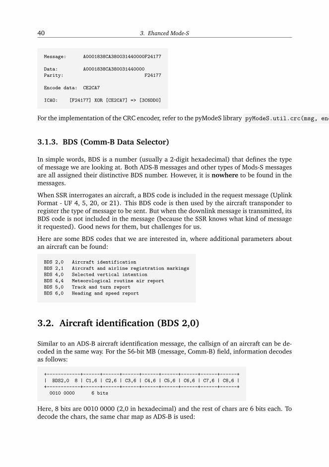
40 3. Ehanced Mode-S
Message: A0001838CA380031440000F24177
Data: A0001838CA380031440000
Parity: F24177
Encode data: CE2CA7
ICAO: [F24177] XOR [CE2CA7] => [3C6DD0]
For the implementation of the CRC encoder, refer to the pyModeS library pyModeS.util.crc(msg, encode=True)
3.1.3. BDS (Comm-B Data Selector)
In simple words, BDS is a number (usually a 2-digit hexadecimal) that defines the typeof message we are looking at. Both ADS-B messages and other types of Mods-S messagesare all assigned their distinctive BDS number. However, it is nowhere to be found in themessages.
When SSR interrogates an aircraft, a BDS code is included in the request message (UplinkFormat - UF 4, 5, 20, or 21). This BDS code is then used by the aircraft transponder toregister the type of message to be sent. But when the downlink message is transmitted, itsBDS code is not included in the message (because the SSR knows what kind of messageit requested). Good news for them, but challenges for us.
Here are some BDS codes that we are interested in, where additional parameters aboutan aircraft can be found:
BDS 2,0 Aircraft identification
BDS 2,1 Aircraft and airline registration markings
BDS 4,0 Selected vertical intention
BDS 4,4 Meteorological routine air report
BDS 5,0 Track and turn report
BDS 6,0 Heading and speed report
3.2. Aircraft identification (BDS 2,0)
Similar to an ADS-B aircraft identification message, the callsign of an aircraft can be de-coded in the same way. For the 56-bit MB (message, Comm-B) field, information decodesas follows:
+------------+------+------+------+------+------+------+------+------+
| BDS2,0 8 | C1,6 | C2,6 | C3,6 | C4,6 | C5,6 | C6,6 | C7,6 | C8,6 |
+------------+------+------+------+------+------+------+------+------+
0010 0000 6 bits
Here, 8 bits are 0010 0000 (2,0 in hexadecimal) and the rest of chars are 6 bits each. Todecode the chars, the same char map as ADS-B is used:

3.3. Selected intention (BDS 4,0) 41
’#ABCDEFGHIJKLMNOPQRSTUVWXYZ#####_###############0123456789######’
Example:
MSG: A000083E202CC371C31DE0AA1CCF
DATA: 202CC371C31DE0
BIN: 0010 0000 001011 001100 001101 110001 110000 110001 110111 100000
HEX: 2 0
DEC: 11 12 13 49 48 49 55 32
CHR: K L M 1 0 1 7 _
ID: KLM1017
3.3. Selected intention (BDS 4,0)
In BDS 4,0, information such as aircraft selected altitude and barometric pressure settingsare given. The 56-bit MB field is structured as follows:

42 3. Ehanced Mode-S
+---------------------------------------+------+------+
| FIELD | MB |N-BITS|
+=======================================+======+======+
| Status | 1 | 1 |
+---------------------------------------+------+------+
| MCP/FCU selected altitude | 2 | 12 | **
| | | |
| range = [0, 65520] ft | | |
| | | |
| LSB: 16 ft | 13 | |
+---------------------------------------+------+------+
| Status | 14 | 1 |
+---------------------------------------+------+------+
| FMS selected altitude | 15 | 12 | **
| | | |
| range = [0, 65520] ft | | |
| | | |
| LSB: 16 ft | 26 | |
+---------------------------------------+------+------+
| Status | 27 | 1 |
+---------------------------------------+------+------+
| Barometric pressure setting | 28 | 12 | **
| -> Note: actual value minus 800 | | |
| | | |
| range = [0, 410] mb | | |
| | | |
| LSB: 0.1 mb | 39 | |
+---------------------------------------+------+------+
| Reserved | 40 | 8 |
| -> set to ZEROS | | |
| | 47 | |
+---------------------------------------+------+------+
| Status | 48 | 1 |
| -> next 3 fields | | |
+---------------------------------------+------+------+
| Mode: VNAV | 49 | 1 |
+---------------------------------------+------+------+
| Mode: Alt hold | 50 | 1 |
+---------------------------------------+------+------+
| Mode: Approach | 51 | 1 |
+---------------------------------------+------+------+
| Reserved | 52 | 2 |
| -> set to ZEROS | 53 | |
+---------------------------------------+------+------+
| Status | 54 | 1 |
+---------------------------------------+------+------+
| Target alt source | 55 | 2 |
| -> 00: Unknown | | |
| -> 01: Aircraft altitude | | |
| -> 10: FCU/MCP selected altitude | | |
| -> 11: FMS selected altitude | 56 | |
+---------------------------------------+------+------+
An example:

3.4. Track and turn (BDS 5,0) 43
MSG: A000029C85E42F313000007047D3
MB: 85E42F31300000
---------------------------------------------------------------------------------
MB BIN: 1 000010111100 1 000010111100 1 100010011000 00000000 0 0 0 0 00 0 00
---------------------------------------------------------------------------------
STATUS: 1
MCP: 188 (x16)
---------------------------------------------------------------------------------
STATUS: 1
FMS: 188 (x16)
---------------------------------------------------------------------------------
STATUS: 1
BARO: 2200 (x0.1 + 800)
---------------------------------------------------------------------------------
FINAL: 3008 ft 3008 ft 1020 mb
---------------------------------------------------------------------------------
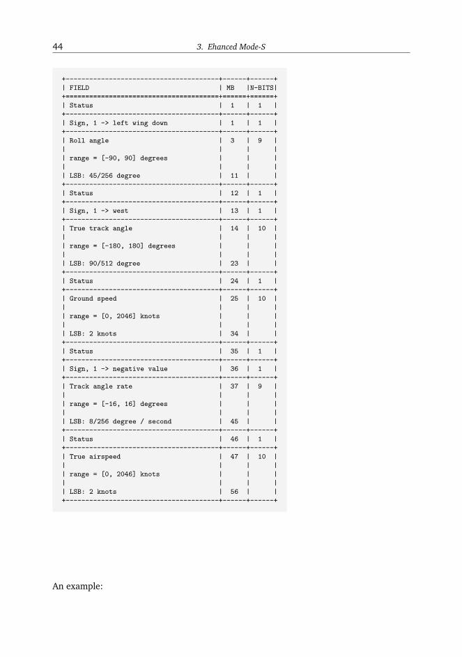
3.4. Track and turn (BDS 5,0)
Within the BDS 5,0 message, five different types of aircraft states are given, mostly relatedwith the turns:
• roll angle
• true track angle
• ground speed
• track angle rate
• true airspeed
The 56-bit MB field is structured as follows:
44 3. Ehanced Mode-S
+---------------------------------------+------+------+
| FIELD | MB |N-BITS|
+=======================================+======+======+
| Status | 1 | 1 |
+---------------------------------------+------+------+
| Sign, 1 -> left wing down | 1 | 1 |
+---------------------------------------+------+------+
| Roll angle | 3 | 9 |
| | | |
| range = [-90, 90] degrees | | |
| | | |
| LSB: 45/256 degree | 11 | |
+---------------------------------------+------+------+
| Status | 12 | 1 |
+---------------------------------------+------+------+
| Sign, 1 -> west | 13 | 1 |
+---------------------------------------+------+------+
| True track angle | 14 | 10 |
| | | |
| range = [-180, 180] degrees | | |
| | | |
| LSB: 90/512 degree | 23 | |
+---------------------------------------+------+------+
| Status | 24 | 1 |
+---------------------------------------+------+------+
| Ground speed | 25 | 10 |
| | | |
| range = [0, 2046] knots | | |
| | | |
| LSB: 2 knots | 34 | |
+---------------------------------------+------+------+
| Status | 35 | 1 |
+---------------------------------------+------+------+
| Sign, 1 -> negative value | 36 | 1 |
+---------------------------------------+------+------+
| Track angle rate | 37 | 9 |
| | | |
| range = [-16, 16] degrees | | |
| | | |
| LSB: 8/256 degree / second | 45 | |
+---------------------------------------+------+------+
| Status | 46 | 1 |
+---------------------------------------+------+------+
| True airspeed | 47 | 10 |
| | | |
| range = [0, 2046] knots | | |
| | | |
| LSB: 2 knots | 56 | |
+---------------------------------------+------+------+
An example:

3.5. Heading and speed (BDS 6,0) 45
MSG: A000139381951536E024D4CCF6B5
MB: 81951536E024D4
---------------------------------------------------------------------------------
MB BIN: 1 0 000001100 1 0 1010001010 1 0011011011 1 0 000000100 1 0011010100
---------------------------------------------------------------------------------
STATUS: 1
SIGN: +
ROLL: 12 (x45/256)
---------------------------------------------------------------------------------
STATUS: 1
SIGN: +
TRACK ANGLE: 650 (x90/512)
---------------------------------------------------------------------------------
STATUS: 1
GROUND SPEED: 219 (x2)
---------------------------------------------------------------------------------
STATUS: 1
SIGN: +
TRACK ANGLE RATE: 4 (x8/256)
---------------------------------------------------------------------------------
STATUS: 1
TRUE AIRSPEED: 212 (x2)
---------------------------------------------------------------------------------
FINAL: 2.1 deg 114.3 deg 438 kt 0.1 deg/s 424 kt
---------------------------------------------------------------------------------
Of course, all fields are not always available in each of DBS 5,0 message. For the infor-mation that is not available, status bits are set to 0.
3.5. Heading and speed (BDS 6,0)
Within the BDS 6,0 message, five different types of aircraft states are given:
• magnetic heading
• indicated airspeed
• Mach number
• barometric altitude rate
• inertial vertical rate
The 56-bit MB field is structured as follows:

46 3. Ehanced Mode-S
+---------------------------------------+------+------+
| FIELD | MB |N-BITS|
+=======================================+======+======+
| Status | 1 | 1 |
+---------------------------------------+------+------+
| Sign, 1 -> West | 1 | 1 |
+---------------------------------------+------+------+
| Magnetic heading | 3 | 10 |
| | | |
| range = [-180, 180] degrees | | |
| | | |
| LSB: 90/512 degree | 12 | |
+---------------------------------------+------+------+
| Status | 13 | 1 |
+---------------------------------------+------+------+
| Indicated airspeed | 14 | 10 |
| | | |
| range = [0, 1023] knots | | |
| | | |
| LSB: 1 knots | 23 | |
+---------------------------------------+------+------+
| Status | 24 | 1 |
+---------------------------------------+------+------+
| Mach number | 25 | 10 |
| | | |
| range = [0, 4.092] Mach | | |
| | | |
| LSB: 2.048 / 512 Mach | 34 | |
+---------------------------------------+------+------+
| Status | 35 | 1 |
+---------------------------------------+------+------+
| SIGN 1 -> Below | 36 | 1 |
+---------------------------------------+------+------+
| Barometric altitude rate | 37 | 9 |
| | | |
| range = [-16384, 16352] ft/min | | |
| | | |
| LSB: 32 ft/min | 45 | |
+---------------------------------------+------+------+
| Status | 46 | 1 |
+---------------------------------------+------+------+
| SIGN 1 -> Below | 47 | 1 |
+---------------------------------------+------+------+
| Inertial altitude rate | 48 | 9 |
| | | |
| range = [-16384, 16352] ft/min | | |
| | | |
| LSB: 32 ft/min | 56 | |
+---------------------------------------+------+------+
An example:
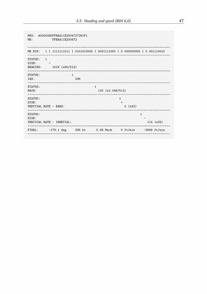
3.5. Heading and speed (BDS 6,0) 47
MSG: A000029CFFBAA11E2004727281F1
MB: FFBAA11E200472
---------------------------------------------------------------------------------
MB BIN: 1 1 1111111011 1 0101010000 1 0001111000 1 0 000000000 1 0 001110010
---------------------------------------------------------------------------------
STATUS: 1
SIGN: -
HEADING: 1019 (x90/512)
---------------------------------------------------------------------------------
STATUS: 1
IAS: 336
---------------------------------------------------------------------------------
STATUS: 1
MACH: 120 (x2.048/512)
---------------------------------------------------------------------------------
STATUS: 1
SIGN: +
VERTIVAL RATE - BARO: 0 (x32)
---------------------------------------------------------------------------------
STATUS: 1
SIGN: -
VERTICAL RATE - INERTIAL: 114 (x32)
---------------------------------------------------------------------------------
FINAL: -179.1 deg 336 kt 0.48 Mach 0 ft/min -3648 ft/min
---------------------------------------------------------------------------------

Chapter 4
About the book
4.1. Related resources
This guide document is shared on GitHub and mode-s.org. Please feel free to help usimproving it.
Links to this guide document:
• (Rst source) https://github.com/junzis/the-1090mhz-riddle
• (Live book) http://mode-s.org
You can download the pyModeS tool from GitHub, which is a Python implementation ofall (and more) message types described here:
• (GitHub) https://github.com/junzis/pyModeS
4.2. Contributors
From TU Delft:
• Junzi Sun, PhD Candidate, TuDelft
• Huy Vu, Master Student, TuDelft
• Jacco Hoekstra, Prof.dr.ir, TuDelft
• Joost EllerBroek, Dr.ir, TuDelft
From GitHub community:
• https://github.com/junzis/the-1090mhz-riddle/graphs/contributors
4.3. Contact
Since the start of the this project, I have received many questions by email. However, thebest way to post your questions is using the GitHub Issues. This way, your questions andmy answers can help others as well:
• Related with this book: https://github.com/junzis/the-1090mhz-riddle/issues
4.4. References 49
• Related with pyModeS: https://github.com/junzis/pyModes/issues
Anyhow, still feel free to drop me a messages at: j.sun-1[at]tudelft.nl
4.4. References
• Technical Provisions for Mode S Services and Extended Squitter. International CivilAviation Organization, 2008.
• Technical Provisions for Mode S Services and Extended Squitter, 2nd Edition. Inter-national Civil Aviation Organization, 2012.
• Annex 10 to the Convention on International Civil Aviation, Aeronautical Telecom-munications. International Civil Aviation Organization, 2002.
• Minimum Operational Performance Standards for 1090 MHz Extended Squitter(DO-260B), RTCA, 2009
• Elementary surveillance (els) and enhanced surveillance (ehs) validation via modes secondary radar surveillance, Project Report ATC-337, Lincoln Lab., MIT, 2008.
• Fundamentals of mode s parity coding, tech. rep., Massachusetts Institute of Tech-nology, Lincoln Laboratory, 1984.
• Dump1090 Project
• A Very Simple ADSB Receiver