tg110dl user s manual - ndt systems
TRANSCRIPT

NDT Systems Inc
TG110DL User’s Manual
TG110DL User’s Manual
1 | P a g e NDT Systems, Inc. 5542 Buckingham Drive, Huntington Beach, CA 92649, PH: 714-893-2438
Table Of Contents Page Number
1. INTRODUCTION 2
2. AREAS OF APPLICATION 3
3. PRINCIPAL OF OPERATION 4
4. DEVICE REFERENCE 5
5. BUTTON AND INDICATOR DESCRIPTIONS 6
6. MAIN MENU FEATURES 8
7. DATA LOGGER 12
8. SCROLLING B-SCAN 14
9. PREPARATION FOR USE 15
10. CALIBRATION PROCEDURES 18
11. GAGING TIPS & TECHNIQUES 19
12. GAGING PRECAUTIONS 21
13. ACCESSORIES 22
14. TROUBLESHOOTING 24
15.WARRANTY 25
APPENDIX: Table of Common Material Sound Velocities 26

TG110DL User’s Manual
2 | P a g e NDT Systems, Inc. 5542 Buckingham Drive, Huntington Beach, CA 92649, PH: 714-893-2438
1. INTRODUCTION
NDT Systems would like to thank you for your purchase of the TG110DL, Handheld Ultrasonic Thickness Gauge.
This instrument provides the best value and feature set currently available, and its robust construction will reward
you with many years of dependable performance.
The TG110DL features the following:
• Membrane-sealed keypad control to simplify its setup and use.
• Backlit 128 X 64 Pixel high contrast, graphic Liquid Crystal Display (LCD) allows for simple, plain text menus.
• Pocket-sized instrument incorporating NDT Systems’ “Easy Grip” Custom Extruded Aluminum Case delivers ultra-
portability.
• Microprocessor-based design offers unparalleled performance for numerous thickness gaging applications.
• Exclusive adjustable “Scan Bar” feature permits a simple, bar graph metered display of thickness for easy & rapid
view of thickness trend.
• Scrolling time-encoded B-Scan, Industry First on a handheld
• Automatic Probe Recognition / Legacy Probe Selection via Menu selection. No need to lose previous Nova 100D
Transducer investment. This makes upgrading even easier !!
• Fully Adjustable Velocity
• 50,000 point Data Logger incorporating a navigable “Spread Sheet” View.
• Single & Two Point Calibration capable
• High & Low Alarm Limits interacting with data logger & high-speed scan mode.
• High Speed Scan Mode incorporates Alarm Capture & Hold
• Data Transfer port permits upload & download of log data
• Digital keypad lock to prevent accidental setup alteration

TG110DL User’s Manual
3 | P a g e NDT Systems, Inc. 5542 Buckingham Drive, Huntington Beach, CA 92649, PH: 714-893-2438
2. AREAS OF APPLICATION
The TG110DL gauges a wide range of thicknesses on metals, plastics, ceramics, glass or virtually any other material
which conducts ultrasound. The actual range is material and application dependent, and requires fairly parallel (or
concentric) measurement surfaces.
The durable custom extruded, “Easy Grip” design allows the unit to withstand the rigors of heavier industrial
environments, while its accuracy makes it suitable for use in less rugged conditions.
A major application for the TG110DL is assessing wall thinning due to corrosion and erosion, including many types
of pitting action, at normal and elevated material temperatures.
Example subjects of evaluation:
Airframes/Aircraft windows Bulkheads
Axles, Wheels, Rails/Casings
Beams/Struts/Castings Billets/Bars/Containers
Boilers/Extrusions Bridges/Flanges
Forgings/Plates/Slabs/Blooms Glass Plate
Pressure Vessels Heat Exchanger
Tubing/Rolls Machined Parts
Ship Hulls/Decking Pipe/Tubing
Steam Lines Plastic Shapes
Pipe/Storage Tanks

TG110DL User’s Manual
4 | P a g e NDT Systems, Inc. 5542 Buckingham Drive, Huntington Beach, CA 92649, PH: 714-893-2438
3. PRINCIPLE OF OPERATION
The TG110DL operates on a principle similar to sonar, but at much higher frequencies and electronic speeds.
The figure below explains the ultrasonic pulse-echo principle that the TG110DL and its dual element probe
(transducer) employ. The probe's transmitter element (T) sends a short ultrasonic pulse into the material. The
pulse, reflected as an echo from the opposite, parallel surface of the material, subsequently returns to the probe's
receiver element (R).
The time it takes for the sound wave to travel from the transmitter to the back wall of the test material, and then
to the receiver is called the “round-trip time” or “Time of Flight” (ToF). The thickness of a test material is
determined by halving the round-trip time and multiplying the result by the material’s characteristic sound
velocity. Characteristic sound velocity differs in various materials, and may even differ in batches of the same
material. By precisely measuring roundtrip time and inputting the appropriate characteristic sound velocity, the
user of the TG110DL is able to gauge accurate and repeatable material thickness results. To find the appropriate
characteristic sound velocity for your application, please refer to the table of material velocities in this manual or
consult your test standard manufacturer.

TG110DL User’s Manual
5 | P a g e NDT Systems, Inc. 5542 Buckingham Drive, Huntington Beach, CA 92649, PH: 714-893-2438
4. DEVICE REFERENCE
Exterior Features, Controls, and Connections
1. ON / OFF Button
2. Up Arrow / Velocity + Button
3. Down Arrow / Velocity – Button
4. Left Arrow / Mode Button Enter Button
5. Right Arrow & B-Scan Start Button
6. Enter Button
7. Menu Button
8. Zero Button
9. Log Access Button
10. Auto-Zero Reference Disc
11. Receiver Input Connector
12. Pulser Output Connector
13. Data Transfer Port
14. Battery Cover Top of Gauge Bottom of Gauge
Measurement Screen
1.Battery Level Meter
2. Scan Bar Scale
3. Scan Bar
4. Coupling Indicator
5. Thickness Reading (in/mm)
6. Current Probe Profile
7. Alarm Indicator
8. Keypad Lock Indicator
7
4
8
2
6 3
1
5
9
10
11 12 13
0
14
1 4
3
6
5
2
7
8

TG110DL User’s Manual
6 | P a g e NDT Systems, Inc. 5542 Buckingham Drive, Huntington Beach, CA 92649, PH: 714-893-2438
5. BUTTON AND INDICATOR DESCRIPTIONS
ON/OFF: Turn on the TG110DL by momentarily depressing the ON/OFF button. Once the power is on and no
buttons are depressed, the display will display NDT Systems, Inc Logo & contact information and software version.
Numeric digits will be displayed once the system boots and is ready for initial calibration. Press and hold for 3/4 of
a Second to turn off. This delay prevents unintentional power off.
UP ARROW / VEL+ BUTTON: In menus the UP ARROW navigates a cursor up in menus. Acts as a Velocity+ or “High
Cal” value increase when in the main measurement screen. UP Arrow also navigates a cursor up in menus.
DOWN ARROW / VEL- BUTTON: In menus the DOWN ARROW navigates a cursor down in menus. Acts as a
Velocity- or “High Cal” value decrease when in the main measurement screen.
To display the ultrasonic velocity currently in memory, depress the up or down arrow momentarily. Velocity will be
displayed below thickness display area.
Scrolling Commands: The Scroll Commands are active when adjusting the velocity up or down. Scroll the
velocity/thickness readout by depressing either the up or down arrow to respectively increase or decrease the
value. Scrolling initially moves at a slow rate, then, after several seconds. it appreciably increases. Release the
scroll command pushbutton to stop the scrolling action. The change in scroll rate allows (1) coarse, large numerical
display changes in a short period of time by continuous command depression or (2) fine, small numerical display
changes - as small as one unit - by quick momentary depression (bumping) of the command.
LEFT ARROW / MODE BUTTON: In menus the LEFT ARROW decreases associated menu values or to navigate a
cursor to the left. Acts as a shortcut to cycle thought the THICKNESS MODE values.
RIGHT ARROW / SCAN BUTTON: In menus the RIGHT ARROW increases associated menu values or to navigate a
cursor to the right. Acts as a shortcut to the Scrolling B-Scan Mode from the main screen.
ENTER BUTTON: ENTER serves to activate various features throughout the TG110DL’s menu structure. ENTER also
serves to enter the current value of thickness into the selected cell of a LOG, while in the LOG mode.
MENU BUTTON: Access to the TG110DL’s special functions are available using this key. Press MENU while in a
menu to return to the main measurement screen
ZERO BUTTON: ZERO compensates for the individual characteristics of the specific probe in use.
DO NOT zero the probe on any other material sample except the Auto Zero Reference Disc, as it will cause
substantial gaging errors.
LOG BUTTON: Access to the TG110DL’s data logging features. Use the LOG menu to start a NEW LOG (only choice
of no other log exists), view an existing LOG, edit an existing LOG, ADD readings to an existing LOG or delete
existing LOGs.
TG110DL User’s Manual
7 | P a g e NDT Systems, Inc. 5542 Buckingham Drive, Huntington Beach, CA 92649, PH: 714-893-2438
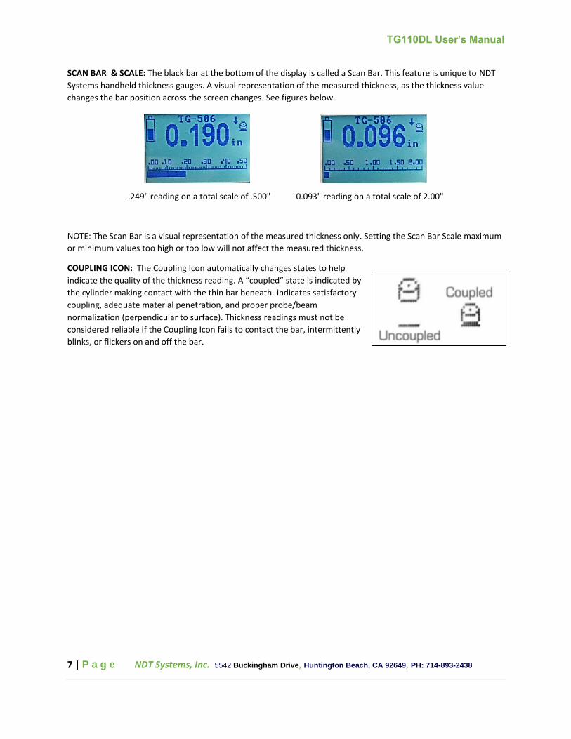
SCAN BAR & SCALE: The black bar at the bottom of the display is called a Scan Bar. This feature is unique to NDT
Systems handheld thickness gauges. A visual representation of the measured thickness, as the thickness value
changes the bar position across the screen changes. See figures below.
.249" reading on a total scale of .500" 0.093" reading on a total scale of 2.00"
NOTE: The Scan Bar is a visual representation of the measured thickness only. Setting the Scan Bar Scale maximum
or minimum values too high or too low will not affect the measured thickness.
COUPLING ICON: The Coupling Icon automatically changes states to help
indicate the quality of the thickness reading. A “coupled” state is indicated by
the cylinder making contact with the thin bar beneath. indicates satisfactory
coupling, adequate material penetration, and proper probe/beam
normalization (perpendicular to surface). Thickness readings must not be
considered reliable if the Coupling Icon fails to contact the bar, intermittently
blinks, or flickers on and off the bar.

TG110DL User’s Manual
8 | P a g e NDT Systems, Inc. 5542 Buckingham Drive, Huntington Beach, CA 92649, PH: 714-893-2438
6. MAIN MENU FEATURES
Refer to the flow diagram below for the Menu selection tree. Press MENU on the keypad to move from the
measurement screen to the Menu screen.
DISPLAY: From the Menu screen place the cursor over the Display icon using the UP or DOWN buttons and press
the ENTER button. In the display menu the four available functions are “Adjust Scale”, “Backlight”, “Contrast”, and
“Units”).
Adjust Scale The Scan Bar Scale is user adjustable and can start and end at any
value within the TG110DL specifications. Suggested scale values might be 10%
over the maximum value of expected thickness to be measured. For instance, if
the material under test is never expected to exceed 0.500" in thickness then a
good maximum scale value would be 0.550". This will give the greatest amount
of visual motion within the range of thickness. If on the other hand, the max
thickness were still 0.500" and the scale were set to 5.00" then the range of
motion would be a very small proportion of the total scale.
To adjust the Scan Bar scale, press the press the MENU button and select ”Display”, then “Adjust Scale”. From this
point simply set the “Start” value to the appropriate minimum expected thickness using the LEFT and RIGHT
ARROW buttons. Then use the DOWN ARROW button to select “Stop” and adjust this value to the maximum
expected thickness value using the LEFT and RIGHT ARROW buttons. Be sure to keep this value within expected
thickness range for maximum effectiveness.

TG110DL User’s Manual
9 | P a g e NDT Systems, Inc. 5542 Buckingham Drive, Huntington Beach, CA 92649, PH: 714-893-2438
Backlight: The backlight has three settings: AUTO, OFF, and ON. AUTO: the backlight will turn on automatically
when the transducer is coupled with the part under test, or when a button on the keypad is pressed. The backlight
will turn off automatically after approximately 5 seconds. OFF: The backlight will stay off indefinitely. ON: The
backlight will remain on continuously as long as the instrument is powered on.
NOTE: If the gauge is being used in an area with high ambient light, the backlight may not be needed. With the
backlight turned off battery life will be increased significantly. As it becomes more difficult to see the display in
darkened conditions, the backlight can be turned to the AUTO or ON settings.
Contrast: Scrolling the contrast value down will darken the display and scrolling the contrast value up will lighten
the display.
Units: Allows the operator to select the measurement units in inches (in) or millimeters (mm).
SELECT PROBE: From the Menu screen, move the cursor down to SELECT PROBE
and press the ENTER button to access the transducer selection menu. A list of
transducer part numbers will appear, allowing the user to select current probe.
The default probe is AUTO, which utilizes NDT Systems' patented automatic
probe recognition. In this mode the gauge has been set up for optimum
performance with the availa ble line of transducers specifically designed for the
TG110DL. Please see the accessories page for other available transducers.
Also available in the SELECT PROBE menu is a library list of legacy NOVA Series transducers. These transducers
were originally provided with the NDT Systems, Inc Nova 100D which has been available for many years. The items
on this list allow you to use your existing investments in Nova series transducers. In time this list will be increased
to support other transducers as well. These notifications will be available on the NDT Systems web site at
www.NDTSystems.com.
2 POINT CALIBRATION: An additional means of calibrating the TG-110DL to a
specific material. From the Menu screen, move the cursor down to 2 POINT CAL
and press the ENTER button to access the 2-point calibration setup display.
Perform the calibration of the low thickness and high thickness values from this
screen. Accuracies may be impr oved while using this calibration method,
particularly on smaller diameter piping or elbows. You will however, need a
sample material type you wish to measure with at least two known thickness points. To use this mode the user
places the transducer over the minimum thickness value to be measured and uses the right and left arrow buttons
to scroll the “Lo Thick” number to the known minimum thickness value. Scroll down to “Hi Thick” then place the
transducer on upper thickness value and again use the right and left arrow buttons to scroll to that known value.
While coupled to high thickness, press menu to save the calibration and return to the previous menu.
GAIN: From the Menu screen, move the cursor down to GAIN and use the LEFT and RIGHT arrow buttons to switch
between “High” and “Low”. This feature allows the user some flexibility when adjusting to various materials and
surface conditions. The default setting is “High”, but “Low should be used when measuring an extremely
acoustically conductive material like aluminum.

TG110DL User’s Manual
10 | P a g e NDT Systems, Inc. 5542 Buckingham Drive, Huntington Beach, CA 92649, PH: 714-893-2438
ALARMS: From the Menu screen, move the cursor down to ALARMS and press the
ENTER button to access the alarm settings. There are four alarm modes, “Off”,
“Lo”, “Hi”, and “Lo/Hi”. Three modes allows the user to set a range of acceptable
thicknesses. Once the measured thickness falls outside that range, a red LED
indicator located near the menu button will illuminate, warning the user that the
measured thickness met one of the alarm conditions. “Off” prevents the alarm
from triggering. “Lo” triggers an alarm when the measured thickness falls below a set thickness. “Hi” triggers an
alarm when the measured thickness rises abov e a set thickness. “Lo/Hi” triggers and alarm when the measured
thickness falls below a set thickness or rises above a se t upper bound. The alarm thicknesses are set by moving the
cursor to either the LOW or HIGH menu item and then using the RIGHT or LEFT button to scroll to the appropriate
thickness value. The alarm mode is also interactive with the Min. Hold mode, as well as the data logger discussed
below.
THICKNESS MODE: From the Menu screen, move the cursor down to THICKNESS
MODE and press the ENTER key to access the various measurement modes.
Normal: In Normal thickness mode, the main display screen will present only the
current thickness value being measured. The Scan Bar will also relate to the
measured thickness. Normal is the default setting.
Differential: The Differential thickness mode displays the difference between the measured thickness and a user
defined thickness value. To define a thickness value, use the UP and DOWN arrow buttons to adjust the small
number below the primary thickness reading and press the ENTER button. The primary thickness will now display a
reading in inches that is greater or less than the user defined thickness value. A quick way to set the defined
thickness value while in Differential thickness mode is to set the probe on a test block of the desired value and
then press the ENTER key. The nominal value will then be set to the thickness of the test block.
NOTE: The gauge must be calibrated to the test material prior to using the Differential Thickness Mode to ensure
correct readings.
Min. Hold: While in this mode the user can scrub across the surface of a part and the gauge will capture and
display the minimum thickness measured during that scrubbing. Press the ENTER key to clear the value and start a
new scrub.
Through-Paint (Option): This mode allows the user to measure the thickness of a test material through an applied
coating. This thickness mode is available as an optional software extra. To check if a gauge is loaded with this
software, refer to the software version number at the top left of the power on splash screen. A gauge with
Through-Paint capability will have a “P” at the end of the version number (e.g. “v1.56P”). A Through-Paint capable
probe is required in to use this mode, as the coating can interfere with a standard probe’s ability to transmit sound
into the test material. The NDT Systems TG-560P Through-Paint transducer is available separately or bundled with
the TG-110DL (Order TG-110 PKG 560P).
NOTE: When using a Through-Paint transducer, it is not necessary to zero the probe.

TG110DL User’s Manual
11 | P a g e NDT Systems, Inc. 5542 Buckingham Drive, Huntington Beach, CA 92649, PH: 714-893-2438
Velocity (Option): This mode allows the user to calculate and set material velocity based on a known thickness.
This thickness mode is available as an optional software extra. To check if a gauge is loaded with this software,
refer to the software version number at the top left of the power on splash screen. A gauge with Velocity gaging
capability will have a “V” at the end of the version number (e.g. “v1.56V”). To use this mode, make sure the probe
is “zeroed”, then select VELOCITY from the Thickness Mode menu. Use the UP and DOWN arrow buttons to set a
nominal thickness and couple the probe to a material of that same thickness. The main numerical display will show
the corresponding velocity value. Press ENTER to save the gauge velocity value to the displayed value. Press the
LEFT/MODE button to return to the main measuring screen and begin taking measurements.
NOTE: The TG110DL cannot be loaded with both the Through-Paint and Velocity software packages.

TG110DL User’s Manual
12 | P a g e NDT Systems, Inc. 5542 Buckingham Drive, Huntington Beach, CA 92649, PH: 714-893-2438
7. DATA LOGGER: Thickness readings can be saved for later review and presentation using the data logger features
of the TG-110DL. Data logs are displayed either in a spreadsheet type view or a linear list on the screen. The user
has available of total of 50,000 data points, where each saved thickness in a data log is one data point. Each data
log file can be named with up to 32 alphanumeric characters. Pressing the LOG button on the keypad enters the
data logger mode. If no data log files currently exist in the data logger, the screen will display NEW only. If there is
at least one other data log file, then the screen will display the number of stored data log files at the top of the
screen, and NEW, REVIEW or ERASE ALL as menu options.
New: Pressing NEW will create a new data log and present a menu with three choices, “Log Type”, “Edit Name”,
and “Create”.
Log Type: Select the Log Type by using the RIGHT and LEFT arrow keys. The two
options are “Linear” and “Grid”. The data log type “Linear” will define a
horizontal list with the user specified number of entries. When selecting the
“Grid” mode, a spreadsheet type of data log will be defined by numbered rows &
columns. The user will be prompted to set the number of rows and columns for
the data log.
Edit Name: When Edit Name is selected from the NEW LOG FILE menu the user is
presented with an alphanumeric screen and a flashing cursor. The data log file is
named by moving this cursor through the alphanumeric field and pressing ENTER
on each desired character. If no name is defined, the TG110DL will assign the next
available numeric value by default. Press the menu button when finished naming
the data log to return to the NEW LOG FILE menu.
Create: This menu prompts the user for the either the number of Points if the LINEAR data log type was selected,
or the number of Rows and Columns if the GRID data log type was selected. Select CREATE when finished defining
data log dimensions. A progress bar will appear while the data log is being built, the larger the data log, the more
time required to create it. Once the data log is built, the user is presented with either a linear row of four input
boxes (cells), or a spreadsheet view of four columns and three rows. Above the boxes (cells) is an indication of the
current row and column. A flashing cursor occupies the current cell. To navigate to the cells not displayed on the
screen, use the arrow buttons to move the cursor to the edges of the screen and press the arrow button once
more. The display will shift and display the next cell in the series. By default, the cursor will start in row one and
column one.

TG110DL User’s Manual
13 | P a g e NDT Systems, Inc. 5542 Buckingham Drive, Huntington Beach, CA 92649, PH: 714-893-2438
ENTERING DATA: To enter a value in a data log, hold the transducer on the area of
interest and press the ENTER key when the reading is stable. The value measured
will be recorded in the currently flashing cell of the data log. To enter the next
value, use the RIGHT or LEFT arrow buttons to move to a new cell and repeat the
process above. The value in the current cell can be overwritten by pressing ENTER
again if a mistake has been made.
The user has total flexibility to scroll throughout the spreadsheet. For instance, the user may elect to enter the
first data point in row 6 column 7 while leaving the other cells blank or null. The data log will be saved with as
many or few points as entered.
Once finished entering data, pressing MENU will return the user to a screen which will allow the ability to view the
current data log, save more readings, edit the data log file name, or erase the data log. The current data log name
will be identified at the top of the screen.
NOTE: All readings stored & displayed in the log will be the actual thickness measured. You may choose to view the
thickness in differential mode, however, the actual thickness will be logged when pressing enter
Review: Select “Review” to access saved data logs. Use the UP arrow or DOWN arrow buttons and press ENTER to
navigate to the desired data log. Once a data log is selected, the user may select one of the following options,
“View Log”, “Log Readings” (to add additional thickness readings to the currently selected data log), “Edit Name”,
or “Erase”.
Erase All: From the main data log menu, select “Erase All” to clear all saved data logs. A prompt will appear
confirming the user’s desire to erase the data logs.
CAUTION! Once the data is cleared from memory, it should be considered unrecoverable.
DATA TRANSFER: The files in the data logger may be uploaded to a Windows-based PC via the TG110-DTP Data
Transfer software program. Instructions for this program can be found in its associated user's manual. This
software and the necessary cable needed to connect the TG-110DL to your computer are included in all TG-110DL
packages.
TG110DL User’s Manual
14 | P a g e NDT Systems, Inc. 5542 Buckingham Drive, Huntington Beach, CA 92649, PH: 714-893-2438
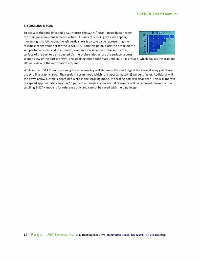
8. SCROLLING B-SCAN
To activate the time encoded B-SCAN press the SCAN / RIGHT arrow button when
the main measurement screen is active. A series of scrolling dots will appear,
moving right to left. Along the left vertical axis is a scale value representing the
thickness range value set for the SCAN BAR. From this point, place the probe on the
sample to be tested and in a smooth, even motion slide the probe across the
surface of the part to be inspected. As the probe slides across the surface, a cross-
section view of the part is drawn. The scrolling mode continues until ENTER is pressed, which pauses the scan and
allows review of the information acquired.
While in the B-SCAN mode pressing the up arrow key will eliminate the small digital thickness display just above
the scrolling graphic area. The result is a scan mode which runs approximately 25 percent faster. Additionally, if
the down arrow button is depressed while in the scrolling mode, the scaling dots will disappear. This will improve
the speed approximately another 10 percent although any horizontal reference will be removed. Currently, the
scrolling B-SCAN mode is for reference only and cannot be saved with the data logger.

TG110DL User’s Manual
15 | P a g e NDT Systems, Inc. 5542 Buckingham Drive, Huntington Beach, CA 92649, PH: 714-893-2438
9. PREPARATIONFOR USE
The TG110DL comes with two AA-size alkaline batteries installed in its battery chamber. To check for satisfactory
battery life, press the ON/OFF touch command to turn power on. A Battery Icon appears on the left side of the LCD
display indicating the current battery charge level. Approximately 150 hours of typical use remains from a fresh set
of batteries. If the display readout fails to register more than 20% scale then the batteries need replacement.
When charge level becomes marginal, the Power-Guard Marginal Cutoff feature automatically turns the power off
until the batteries are replaced.
Battery Replacement: Loosen (counterclockwise) the battery cover on the bottom of the gauge with a small coin
or screwdriver. Remove the discharged batteries and replace them with two new AA-size alkaline or NiMH
rechargeable batteries. Install them with proper polarity, negative side to be in contact with the battery cover.
Replace the battery cover into the gauge and tighten by turning clockwise. Re-establish the gauge calibration
settings whenever the batteries are completely discharged, removed, or replaced.
Probe Selection: A variety of probes are available to optimize performance for the broad spectrum of gaging
applications that may be encountered. The TG-506 Transducer should be used for most applications and surface
temperatures up to about 225ºF.
There are also the TG-556, TG-790, and TG-208 transducers designed for intermittent contact of surface
temperatures up to 600ºF (316 C).
An Ultrahigh-temperature probe having a fused quartz delay line, like the TQ-506, should be used on surface
temperatures between 600 to 1000ºF (316-538 C).
Smaller sized Mini-Probes like the TG-502 and TG-702 transducers are available for use on smaller surface radii or
for gaging in confined locations.
Refer to the probe list in the Accessories section to select the best probe suited for your application. For best
results, use probes manufactured by NDT Systems, Inc whenever possible.
Probe Attachment: All transducers except the “Mini-Probes” have a detachable dual cable for connecting to the
TG110DL. Connect the dual cable (LMD1) to the probe using the cable end with the smaller red-sleeved and black-
sleeved Microdot screw-on connectors (certain transducers may require attaching the red-sleeved and black-
sleeved connectors to the correspondingly marked polarized connectors). Connect the other end of the dual cable
with the larger push-on/pull-off LEMO connector to the corresponding connectors located on top of the gauge. Be
certain to connect the red-dot marked connector to the gauge connector with the adjacent red dot.

TG110DL User’s Manual
16 | P a g e NDT Systems, Inc. 5542 Buckingham Drive, Huntington Beach, CA 92649, PH: 714-893-2438
Couplant Selection: A liquid couplant film is always needed to transfer the high
frequency ultrasonic energy between the probe and the material. Typically,
couplant is generously applied to the material surface, although it sometimes
can be initially applied to the bottom of the probe (as during some high
temperature applications). The type of couplant used is very important for
optimum performance.
Smooth material surfaces require a lower viscosity couplant, such as water,
glycerin or grease as necessary. Special high temperature couplants should be
used on surfaces above 175 deg F.
NDT Systems offers numerous ultrasonic couplants which cover virtually all
application areas for the TG110DL. These specially formulated couplants should
be used whenever possible.
Reference Samples: To calibrate the TG110DL, a known thickness or a known ultrasonic velocity for the material is
needed. These calibration techniques require. at least initially, a reference sample representing the material to be
gauged. The closer the reference sample matches the actual material, the better the gaging accuracy. To
compensate for calibration factors, such as material composition (most important), micro-structure heat treat
condition (alloys), grain direction (alloys), thickness ranges, surface roughness and contour, the 'ideal' reference
material would come from pieces of the actual material. This type of reference sample is used for critical
applications for those requiring maximum gaging accuracy.
For most applications, satisfactory gaging accuracy can be obtained by using a single reference sample. This sample
should have the same composition and same nominal thickness (measured within required tolerances) as the
actual material/product. The material or product itself is often used with a micrometer to accurately measure an
accessible representative thickness.
When gaging thin materials that approach the lower performance limits of the gauge/probe combination,
experiment with reference samples to determine the actual lower limit. Do not gauge materials thinner than this
limit (See Gaging Precautions).
If a thickness range is anticipated, then use a reference sample that represents the thicker end of the range.
For exceptionally large thickness ranges, particularly in alloys where micro structural variations occur, use separate
samples and calibration setups at selected intervals across the range.
Many wrought and cast metal microstructures exhibit directionality that, depending upon the beam direction.
causes a slight variation in ultrasonic velocity. For improved accuracy, reference samples should have the same
directionality/sound beam orientation as that of the material to be gauged.
A machined step-wedge is a commonly used and convenient reference sample that has thicknesses across the
range of interest (flat steps for flat materials or concentric steps for smaller-diameter tubing).
Under certain conditions, the published ultrasonic velocity value for a given material (see velocity table in
appendix) can be used instead of a reference sample. Such a procedure is only satisfactory if the material has a
known and constant velocity and the intended application does not require relatively high gaging precision. This
approach is reasonable for many of the simpler, more-rugged applications involving the gaging of mild steel (plain
carbon steel). In some cases. published velocity values will be found to differ appreciably depending upon the
source of the publication. This is due to inherent material chemical/physical variations. Published velocity data
tend to be useful only where approximate or relatively coarse thickness gaging precision is acceptable.
TG110DL User’s Manual
17 | P a g e NDT Systems, Inc. 5542 Buckingham Drive, Huntington Beach, CA 92649, PH: 714-893-2438
AUTO-HOLD: When a coupled probe is lifted from the material surface, the Last thickness reading taken is
conveniently retained on the display until either another thickness reading is taken, the two-minute non-usage
lapse (Auto-Shutoff) occurs, or ON/VEL is depressed. This Auto-Hold feature does not affect readings as the
coupled probe is scanned over a surface. The display updates approximately four times per second whenever the
probe has valid coupling with the surface of a test object.
AUTO-SHUTOFF: The TG110DL automatically turns itself off approximately three minutes after non-use, thereby
eliminating the need to use the OFF switch. To reset the turnoff timer, take a thickness reading or press the ENTER
key. All TOUCH-COMMAND settings (calibration settings plus Touch Codes) are retained in memory (even when
the gauge turns its power off).
KEYPAD LOCK: Use the keypad lock function to prevent accidental changes to the measurement settings. Engauge
the keypad lock by holding down the ZERO and ON/OFF buttons at the same time until “L” is displayed next to the
battery charge indicator. When locked, only the ON/OFF button will respond to user inputs. To disengage keypad
lock, hold down the ZERO and ON/OFF buttons until the “L” disappears. Full functionality will be restored.
TG110DL User’s Manual
18 | P a g e NDT Systems, Inc. 5542 Buckingham Drive, Huntington Beach, CA 92649, PH: 714-893-2438
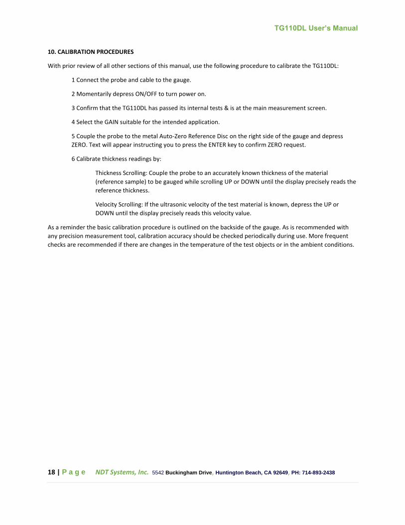
10. CALIBRATION PROCEDURES
With prior review of all other sections of this manual, use the following procedure to calibrate the TG110DL:
1 Connect the probe and cable to the gauge.
2 Momentarily depress ON/OFF to turn power on.
3 Confirm that the TG110DL has passed its internal tests & is at the main measurement screen.
4 Select the GAIN suitable for the intended application.
5 Couple the probe to the metal Auto-Zero Reference Disc on the right side of the gauge and depress
ZERO. Text will appear instructing you to press the ENTER key to confirm ZERO request.
6 Calibrate thickness readings by:
Thickness Scrolling: Couple the probe to an accurately known thickness of the material
(reference sample) to be gauged while scrolling UP or DOWN until the display precisely reads the
reference thickness.
Velocity Scrolling: If the ultrasonic velocity of the test material is known, depress the UP or
DOWN until the display precisely reads this velocity value.
As a reminder the basic calibration procedure is outlined on the backside of the gauge. As is recommended with
any precision measurement tool, calibration accuracy should be checked periodically during use. More frequent
checks are recommended if there are changes in the temperature of the test objects or in the ambient conditions.

TG110DL User’s Manual
19 | P a g e NDT Systems, Inc. 5542 Buckingham Drive, Huntington Beach, CA 92649, PH: 714-893-2438
11. GAGING TIPS & TECHNIQUES
1.Clean Surface: Prior to gaging, always remove performance hindering foreign substances from the material
surface (e.g. dirt, loose scale, corrosion, particles, and flaking paint).
2.Excessive Surface Roughness: Very rough surfaces can cause erratic, extremely low or no thickness readouts. In
such cases, consider scraping, sanding, grinding or filing the surface smooth enough to obtain a proper response
(provided such a procedure and the amount of metal removal are acceptable). High-viscosity couplants, the Special
Power Mode or the Hi-Power Probe may also significantly improve the response.
3.Heavy Machine-Grooved Surfaces: A uniformly-grooved surface, such as produced by a single point cutting tool,
can cause the same undesirable effects. As a remedy, use a high-viscosity couplant and orient the probe's crosstalk
barrier (located on the bottom of the probe) at right angles to the groove (patter) direction. If the above procedure
fails, use the GAIN control located in the MAIN menu. Decrease the GAIN until the undesirable effect disappears,
while assuring proper thickness can still be obtained within the desired expected MIN/MAX thickness range.
4.Use a lower frequency probe if gaging thick materials or materials with large grain structures.
5.Gaging Cylindrical Sections: When gaging cylindrical shapes such as pipe, tubing, tanks, etc., it is vital to establish
probe normality (perpendicularity to surface) and select the proper orientation of the probe's cross-talk barrier.
6.To determine normality, rock the coupled probe back and forth along the curved direction on the material
surface and watch the accompanying decrease/increase action of the thickness readout. Use the minimum
thickness reading, as this represents probe normality.
Selection of probe cross-talk barrier orientation depends upon the material's surface diameter. See the following
probe orientation figure. On large diameters, orient the probe so its barrier is perpendicular to the cylindrical axis
of the material. On smaller diameters, initially orient the probe barrier both perpendicular to and parallel with the
material's cylindrical axis (at the identical location) and then use the direction that gives the smaller thickness
readout.

TG110DL User’s Manual
20 | P a g e NDT Systems, Inc. 5542 Buckingham Drive, Huntington Beach, CA 92649, PH: 714-893-2438
7.Compound Contours: For gaging elbows on cylinders, (also see Paragraph 5), rock the probe for a minimum
reading in both the circumferential and longitudinal directions and then use the smaller of the two minimum
readings. On spherical sections, rock the probe for a minimum reading in one direction and, again. or another
minimum reading with the cross-talk barrier perpendicular to the first. Use the smaller of the two minimum
readings. Compound contours are difficult to gauge, so if successful results cannot be obtained, try using an
ultrasonic flaw detector such as the NDT Systems Raptor or a thickness gauge with ‘A’ Trace capability such as NDT
Systems' TG410.
8. Non-Parallel Surfaces: The surfaces on either side of a section must be relatively parallel or concentric in order
to obtain a satisfactory ultrasonic echo for a thickness reading. Non-parallel or tapered surfaces will produce less
accuracy or no reading at all.
9.Material Temperature Effects: Both the dimensions and the ultrasonic velocity of a material change with
temperature, which, in turn affect calibration. This undesirable effect holds true for the material being gauged as
well as for the probe. Although it is always good practice to re-calibrate when a noticeable change in ambient
temperature occurs, the effect can normally be ignored for modest changes in ambient temperature.
The situation becomes more complex when the material temperature is considerably different than ambient. One
solution is to calibrate on a reference sample at the same temperature as the material. Another solution is to
calibrate on a reference sample at ambient temperature and then add an experimentally derived correction factor
for the temperature of the material.
The gaging of hot steel products is an application where high temperatures will produce significant thickness
readout errors (gauge typically reads thicker than actual), unless some temperature correction or compensation
technique is used.
10.Excessively Attenuative Materials: Some materials (fibrous, porous, large-grained, etc.) may absorb or scatter so
much ultrasound that either a reading cannot be obtained or some abnormal reading (usually abnormally thin)
occurs. In such cases, try a Hi-Power Probe. If gaging is still unsuccessful, use an ultrasonic flaw detector such as
NDT Systems' Avenger EZ or Raptor.
11.Grain Directionality Effects: In many wrought and cast metals, the micro structural properties are directional.
This means the ultrasonic velocity (and calibration) may differ, depending upon the beam direction with respect to
the grain direction. For improved accuracy, always calibrate and subsequently gauge in the same material grain
direction
.

TG110DL User’s Manual
21 | P a g e NDT Systems, Inc. 5542 Buckingham Drive, Huntington Beach, CA 92649, PH: 714-893-2438
12. GAGING PRECAUTIONS
Very Thin Sections: As with any ultrasonic thickness gauge, when the sectional thickness falls below the minimum
operating thickness for the specific probe in use, erroneous readings will result. It is virtually impossible to
precisely specify the minimum thickness which can be gauged with a given probe/TG110DL combination because
the actual minimum thickness depends upon the particular application (material type, contour, surface conditions,
temperature, etc.). Therefore, the minimum thickness limit should be closely approximated by experimentation on
samples of the actual material/product.
One erroneous effect, called "doubling", sometimes occurs when gaging thicknesses fall below the minimum limit.
Another effect, known as "pulse-envelope cycle-jumping," produces a reading somewhat larger than the actual
thickness. It is advisable to double check critical thinner sections by using NDT Systems' NovaScope or an ultrasonic
flaw detector such the Avenger EZ or Raptor.
Pitting Corrosion: Pitted areas on the opposite metal surface can cause unexpected erratic changes in thickness
readout or, in extreme cases, a lack of thickness readout. Very small (especially sharply pointed) pits may even go
undetected (especially isolated single pits). When pitting is either detected or suspected, the area should be very
carefully scanned while changing the orientation of the probe's cross-talk barrier to enhance delectability of the
thinnest pitted spot (s). When positive results cannot be obtained, particularly on critical structures, use NDT
Systems' NovaScope or an ultrasonic flaw detector such the Avenger EZ or Raptor as a supplementary test method.
Material Misidentification: Always verify the type and anticipated thickness of material to be gauged. Erroneous
thickness readouts will result if an instrument is calibrated to a material and thickness other than the test material.
Worn or Malfunctioning Probes: Immediately replace any probe that is malfunctioning or showing excessive or
uneven wear.
Use of the ZERO Command: Zero the probe only on the metal Auto-Zero Reference Disc, located on the front of the
gauge. The instrument will lose calibration if ZERO is depressed while the probe is coupled to any other material.
Abnormal or Unusual Thickness Readings: The operator should always qualify abnormal/questionable thickness
indications. While such indications may be caused by corrosion/erosion, the use of wrong material thickness.
internal flaws, certain other materials, or gauge factors (as discussed).
Material Stacks: It is not possible to gauge the stack thickness of uncoupled material sheets piled upon one
another because ultrasound reflects totally from the bottom surface of the outer sheet.
TG110DL User’s Manual
22 | P a g e NDT Systems, Inc. 5542 Buckingham Drive, Huntington Beach, CA 92649, PH: 714-893-2438
13. ACCESSORIES
Standard Accessories: The standard TG110DL Kit contains the TG110DL gauge (batteries installed), TG-506 Probe,
LMD1 Probe Cable, Plastic Couplant Bottle, Operating Manual.
Optional Accessories: Detachable wrist strap, Flared Probe Holder, Accessory Carrying Case. Other accessories
include Mini-Probes with top or side-mounted integral cables. Ultrahigh-Temperature Probe, Hi-Power Probe,
Probe Cables, Spring-Loaded V-Groove Probe Housings and a Slip-On Protective Leather Case for the gauge.
Optional Software: Through-Paint mode, Velocity gaging mode
Probes:
TG-506 “Standard ”
STANDARD PROBE (-15/F - 250/F) Dual-element, top-mounted microdot connectors, 0.040 to 20.00 inches
thickness range, 5 MHz, 0.375 inch diameter element 0.60 inch diameter by 1.30 inch long case. “Requires LMD1
cable (not included).
TG-560P
THROUGH-PAINT Integrated delay line, Dual-element, top-mounted microdot connectors, 0.110 to 3 inches
thickness range, 5 MHz, 0.375 inch diameter element 0.60 inch diameter by 1.30 inch long case. “Requires LMD1
cable (not included).
TG-556
EXTENDED TEMP STANDARD PROBE (-15/ - 600/ F) Dual-element, top-mounted microdot connectors, 0.040 to
20.00 inches thickness range, 5 MHz, 0.375 inch diameter element 0.60 inch diameter by 1.30 inch long case.
“Requires LMD1 cable (not included).
TG-505
MINI PROBE Dual-element, non-detachable side-mounted cable, 0.040 to 2 inches thickness range, 5 MHz, 0.30
inch diameter element, 0.44 inch diameter by 0.45 inch long case.
TG-508
MINI PROBE Dual-element, non-detachable side-mounted cable, 0.060 to 2 inches thickness range, 5 MHz, 0.30
inch diameter element, 0.44 inch diameter by 0.45 inch long case.
TG-505TM
MINI PROBE Dual-element, non-detachable top-mounted cable, 0.040 inch to 2 inches thickness range, 5 MHz,
0.30 inch diameter element, 0.44 inch diameter by 1.55 inch long case.
TQ-506
ULTRA-HI-TEMP PROBE Dual-element, intermittent operating temperature to approximately 1000°F (538°C), top-
mounted microdot connectors, fused quartz delay line, 0.200 inch to 9.999 inches thickness range, 5 MHz, 0.375
inch diameter element, 0.60 inch diameter by 3.31 inch long case. “Requires LMD1 cable (not included).

TG110DL User’s Manual
23 | P a g e NDT Systems, Inc. 5542 Buckingham Drive, Huntington Beach, CA 92649, PH: 714-893-2438
TG-502
SUBMINIATURE PROBE Dual-element, non-detachable side-mounted cable, 0.050 inch to 1.000 inch thickness
range, 5 MHz, 0.22 inch diameter element, 0.28 inch tip diameter, 0.50 inch grip diameter by 0.75 inch high case.
TG-502TM
SUBMINIATURE PROBE Dual-element, non-detachable top-mounted cable, 0.050 inch to 1.000 inch thickness
range, 5 MHz, 0.22 inch diameter element, 0.28 inch tip diameter, 0.40 inch grip diameter by 1.125 inch high case.
TG-208
HI-POWER PROBE Dual-element, intermittent operating temperature to approximately 600°F (316°C), top-
mounted microdot connectors, 0.200 inch to 50.00 inches thickness range, 2 MHz, 0.60 inch diameter element,
0.90 inch diameter by 1.50 inch long case. “Requires LMD1 cable (not included).
TG-101HR
Dual-element, top-mounted microdot connectors, 0.022 to 2.000 inches thickness range, 10 MHz, 0.25 inch
diameter element, 0.31 inch diameter contact tip. “Requires LMD1 cable (not included).
TG-790
HI-TEMP PROBE Dual-element, intermittent operating temperature to approximately 900°F (482°C), top-mounted
microdot connectors, 0.04 inch to 9.999 inches thickness range, 5 MHz, 0.280 inch diameter element, 0.48 inch
diameter by 2.50 inch long case. “Requires LMD1 cable (not included), compatible with LMD1-S cable.

TG110DL User’s Manual
24 | P a g e NDT Systems, Inc. 5542 Buckingham Drive, Huntington Beach, CA 92649, PH: 714-893-2438
14. TROUBLESHOOTING
If you are experiencing issues with your TG110DL, please refer to the guide below for a list of potential problems
and solutions.
Factory Reset: If the gauge is running slowly, behaving erratically, or exhibiting another issue not included on the
guide above, a factory reset may be recommended. To perform a factory reset, start with the gauge turned off.
Hold the ENTER key, and press the ON/OFF key. A menu will appear titled “Clear Data?”. Three options will appear,
“Clear Setup”, “Clear Log”, and “Setup and Log”. Select “Setup and Log”, and the system will restart with factory
settings.
NOTE: If none of the above actions fix the issues with the TG110DL, please contact NDT Systems for information
about repairs and services.
https://www.ndtsystems.com/repair-and-calibration-service-request

TG110DL User’s Manual
25 | P a g e NDT Systems, Inc. 5542 Buckingham Drive, Huntington Beach, CA 92649, PH: 714-893-2438
15. WARRANTY
NDT Systems, Inc. Standard Terms & Conditions including its Warranty Terms can be found at
https://www.ndtsystems.com/standard-terms-conditions

TG110DL User’s Manual
26 | P a g e NDT Systems, Inc. 5542 Buckingham Drive, Huntington Beach, CA 92649, PH: 714-893-2438
APPENDIX
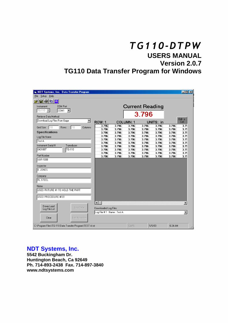
TG110-DTPW USERS MANUAL
Version 2.0.7 TG110 Data Transfer Program for Windows
NDT Systems, Inc. 5542 Buckingham Dr. Huntington Beach, Ca 92649 Ph. 714-893-2438 Fax. 714-897-3840 www.ndtsystems.com

Table Of Contents
1.0 Introduction 2.0 Installing TG110-DTPW
2.0.1 Installation of USB Drivers 2.0.2 Installation of TG110-DTPW
3.0 Running TG110-DTPW 4.0 Getting Started
4.0.1 Settings 4.0.2 Specifications
5.0 Transferring Data
5.0.1 Computer Polling – Manual Method 5.0.2 Computer Polling – Automatic Method 5.0.3 Down Loading Log Files From Your Gage
6.0 Working With The Data
6.0.1 Clearing Data 6.0.2 Editing a Cell 6.0.3 Copying Data to the Clipboard 6.0.4 Saving Your Readings to a File 6.0.5 Opening a File you have Saved 6.0.6 Printing a Report 6.0.7 Importing Data into a Spread Sheet Program
7.0 System Requirements & Contact Information
7.0.1 Hardware 7.0.2 File Format 7.0.3 Contact Information
Licensing Agreement
USB Setup Addendum

1.0 INTRODUCTION TG110-DTPW is designed to provide a simple means of transferring data from NDT Systems’ TG110 series gages to an IBM compatible computer running a Microsoft Windows operating system (XP, Vista, 7). TG110-DTPW will allow you to transfer data from TG110 gages and save it, along with other important report data. The saved file can also be imported into a spreadsheet program for further analyses or reporting, and/or the data can be copied and pasted directly into another program. 2.0 INSTALLING NOVA-DTPW 2.0.1 USB Driver Installation The USB drivers MUST be installed BEFORE connecting your instrument to your computer. Install the USB drivers using the USB Addendum in the USB setup instructions included with this software. 2.0.2 TG110-DTPW data transfer program installation. TG110-DTPW is installed by simply placing the disk into your CD drive, and from the Start menu choosing Run. Then from your CD drive under the TG110- DTPW directory run the file named Setup.exe 3.0 RUNNING NOVA-DTPW TG110-DTPW is run by choosing Programs from the Start menu, then choosing TG110 Data Transfer Program from your program list. The Program name is TG110-dtpw.exe

4.0 GETTING STARTED 4.0.1 Settings These fields are used to setup the communications between the computer and the Nova gage. COM Port: Using the drop down box, select the serial communications port that will be used. Receive Data Method: Using the drop down box, select the Receive Data Method that will be used. Computer Polling – Manual This method will transfer and display the reading on your gage to your computer and allow you to log the readings that you want by clicking on the Log button. Computer Polling – Automatic This method will transfer and display the reading on your gage to your computer as it continuously logs each reading in a continuous flow. Download Log Files from gage This method will transfer Log Files from your gage to your computer. 4.0.2 Specifications These fields may be used to store valuable data about your test setup. Grid Size: These fields are filled in automatically when down loading Log Files from your gage. When using your computer to log readings you will need to use these fields to setup your grid size Log File Name: This field contains the name of your Log File in the gage. Instrument Serial Number: You may use this field to record the serial number of your Nova gage. Transducer: You may use this field to record your transducer part number and serial number. Part Number: You may use this field to record the part number of the item you are inspecting.

Inspector: You may use this field to record the name of the operator performing the inspection. Company: You may use this field to record the name of the company the inspection is being performed for. Notes: You may use these 2 fields to record notes about your inspection. Work order numbers, Procedure numbers, setup notes, etc. 5.0 TRANSFERING DATA
With the proper Settings selected as stated in section 4.0 you are ready to begin. Attach the proper cable between the computer and your TG110 gage. Turn the TG110 gage on. 5.0.1 Computer Polling – Manual Method
Before starting, set up your Grid Size. To begin, click the Begin Acquisition button. You will see the current reading of the gage displayed in the Current Reading box on the computer. To log a reading, select a cell in your grid where you want the reading to be placed. Next click the Log button. This will take the current reading and log it into the cell that you have selected. Each time you click the Log button it will log a reading into the selected cell. To end this process, click the End Acquisition button. 5.0.2 Computer Polling – Automatic Method
Before starting, set up your Grid Size. To begin, click the Begin Acquisition button. You will see the current reading of the gage displayed in the Current Reading box on the computer, and the current reading will also be placed into the cell you select in your grid. This method will continuously log readings until the End Acquisition button is pressed. 5.0.3 Download Log Files from Gage To begin, click the Down Load Log File List button. You will see a box pop up with a list of all the Log Files on your gage. Select the Log Files you would like to down load to your computer. To do this, highlight with your mouse the items in the box you want to select. You may select

multiple lines by holding down your left mouse button and moving your mouse over all of the items you want to copy. You may also hold down the Ctrl key on your keyboard while clicking the items to copy. This allows you to choose individual lines to copy. Click the Down Load Selected Files button to begin loading the files. Click Exit to exit with out downloading any files. After down loading your Log Files, you can view them by choosing the one you would like to view from the list below the grid labeled Downloaded Log Files

6.0 WORKING WITH THE DATA 6.0.1 Clearing All Data
To clear out or delete all of the current data, click the Clear button. This will clear out all of the readings as well as the information in the Specifications area. 6.0.2 Edit a Cell
This feature allows you to edit a cell in your grid. To edit a cell in your grid, click on the cell you would like to edit. Then click the Edit a Cell button. A box will pop up prompting you to edit the cell. Fill in the data you would like in the cell. Click Edit and the new information will be placed into the cell. Click on cancel and the process will be canceled and nothing will be changed. Note when this button is clicked it will stop the acquisition process if you were acquiring data at the time this button was selected. 6.0.3 Copying Data to the Clipboard This feature allows you to copy your grid or specifications data onto the clipboard so you may paste them into another application directly. To do this, highlight with your mouse the items you want to copy. Selecting the grid will copy the entire grid. Click the Copy icon. Once copied to the clipboard, you may use the Paste feature in your other applications to paste the readings into that application.
A second method for using the clipboard is to enable the Automatic Copy to Clipboard feature. Enabling this feature will cause only the thickness reading to be automatically copied to the clipboard each time a reading is logged. This will allow you to run a spreadsheet for example, and use the Paste feature in your application to put the reading into the desired cell as the readings are logged.

To Enable or Disable this feature, click Settings on the Menu Bar. Next, click on Copy to Clipboard. This will pop up a window to allow you to Enable or Disable this feature. 6.0.4 Saving Your Readings to a File To save your readings and Specifications information to disk, simply click on the floppy disk icon or click File, then Save as. The default location to save your files is under your TG-110 Data Transfer Program directory. To select another location, simply choose the drive and path by clicking on the ones you want. Enter the filename you wish to use and then click OK. NOTE: this saves the data currently displayed in the grid and specifications ONLY. If you have downloaded multiple Log Files you will need to select each one you want to save from your Downloaded Log Files list and save each one. To exit with out saving, click Cancel. 6.0.5 Opening a File you have Saved To open a file you have saved, simply click on the open file icon or click File, then Open. The default location to open your files from is under your TG-110 Data Transfer Program directory. To select another location, simply choose the drive and path by clicking on the ones you want. Click on the filename you want to load or enter the file name and click OK. To exit without opening, click cancel.
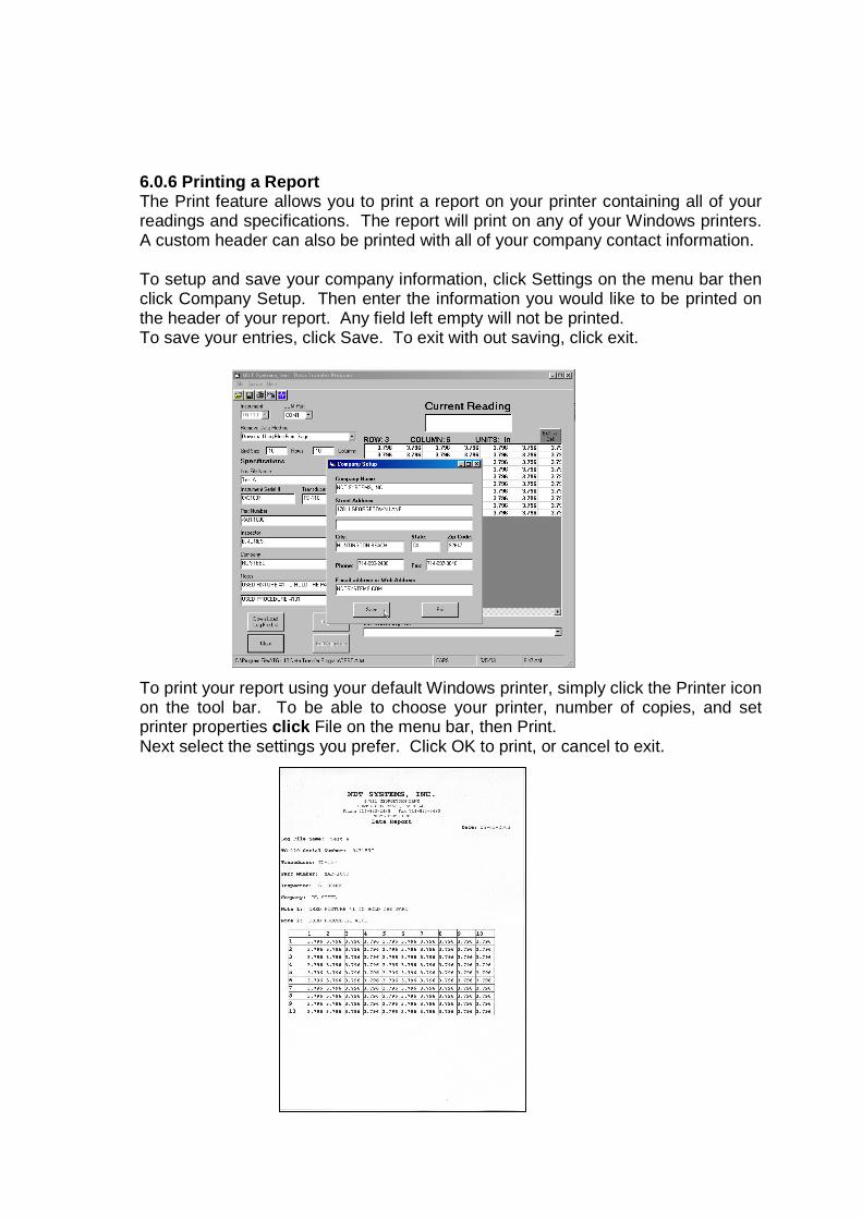
6.0.6 Printing a Report The Print feature allows you to print a report on your printer containing all of your readings and specifications. The report will print on any of your Windows printers. A custom header can also be printed with all of your company contact information. To setup and save your company information, click Settings on the menu bar then click Company Setup. Then enter the information you would like to be printed on the header of your report. Any field left empty will not be printed. To save your entries, click Save. To exit with out saving, click exit. To print your report using your default Windows printer, simply click the Printer icon on the tool bar. To be able to choose your printer, number of copies, and set printer properties click File on the menu bar, then Print. Next select the settings you prefer. Click OK to print, or cancel to exit.

6.0.7 Importing Data into a Spread Sheet Program The following example shows how to import your saved TG-110 Data file into Microsoft Excel. Load Excel and click on Open to open your file. Change the Files of Type to All Files (*.*) Then select your file to load. After selecting your file, you need to setup the format for your spread sheet. The file type is comma delimited. With that in mind, your file needs to be setup as Delimited . At this point you can also choose which line to begin the import on. For example if you are not interested in any of your Settings or Specifications information you can begin the import at line 13 and only import your readings.

Next you need to select the delimiter type. Select Comma only. The Text Qualifier is Quotes (“ ). Next, if you choose, you can set the data type for the columns in your spread sheet. The default is General. Click on Finish to complete your Import.

The format for a Nova Data Transfer file is shown below: Line 1 = Software Version Line 2 = Log File Name Line 3 = Instrument Serial Number Line 4 = Transducer Line 5 =Part Number Line 6 =Inspector Line 7 = Company Line 8 = Notes Line 9 = Notes Line 10 = units Line 11 = Columns Line 12 = Rows Line 13 and beyond = Data When saving your spread sheet file, change the Save as Type to Microsoft Excel Workbook to avoid saving your spread sheet file as the same name/extension as your Nova Data Transfer file.

7.0 SYSTEM REQUIREMENTS & CONTACT INFORMATION
7.0.1 Hardware: Pentium Processor 64 MB RAM Recommend 1024x768 minimum screen size One available COM Port (RS232) 1.75 MB Disk Space 7.0.2 File Format: Line 1 = Software Version Line 2 = Log File Name Line 3 = Instrument Serial Number Line 4 = Transducer Line 5 =Part Number Line 6 =Inspector Line 7 = Company Line 8 = Notes Line 9 = Notes Line 10 = units Line 11 = Columns Line 12 = Rows Line 13 and beyond = Data
7.0.3 Contact Information: NDT Systems, Inc. 5542 Buckingham Dr. Huntington Beach, CA 92649
To see the latest products and services from NDT Systems, inc. , log on to www.NDTSystems.com or simply click on the
NDT Systems, Inc . logo and your default web browser will be launched and take you to our web sight.
• Microsoft Windows and Microsoft Excel are registered trademarks of the Microsoft Corporation

Licensing Agreement Please read carefully the following terms and cond itions. This agreement is made between the Purchaser, (her einafter USER), and NDT Systems, Inc. (hereinafter NDT) for the licensing of TG-110-DTPW. TG-110-DTPW has only commercial use an d the terms of this agreement including the disclai mers and limitations are expressly part of the bargain on which the license to use TG-110-DTPW is granted. Use of TG-110-DTPW i ndicates the USER’S acceptance of the terms and conditions of this licensing agreemen t.
I. License
a) Specifications: TG-110-DTPW substantially confor ms to and performs in accordance with the specifica tions and written documentation provided with TG-110-DTPW.
b) License Rights: This Licensing Agreements gra nts to USER a nonexclusive, nontransferable right t o use this software. c) Restrictions: The software relating to TG-110- DTPW is copyrighted under the laws of the United St ates with copyright
registration pending. Title to TG-110-DTPW and all variations rests with NDT. USER may not rent or lea se TG-110-DTPW without written consent of NDT. At the end of the t erm of this license, USER shall destroy all archiva l copies. User shall not reverse engineer, decompile or disassemble the soft ware.
d) Trade Secret: NDT claims the Source Code to TG -110-DTPW and all variations thereof as a trade sec ret. User, it’s employees, agents and assigns are obligated to main tain the secrecy of that source code.
II. Warranties and Limitations
a) Hardware: This software is designed to be used only with IBM compati ble computers using Windows operating systems. NDT is not responsible for damage, injury to persons or eq uipment or monetary loss resulting from use of this software with any other equipment.
b) NDT warrants this software will substantial ly conform to and perform in accordance with the accompanying specifications and other documentation. NDT further warrants the disk on which program is recorded to be free from defects in materials and workmanship under normal and recom mended use and serviced for 120 days from delivery and will replace any disk which is defective during that period.
c) Disclaimer: As part of the bargain in entering into this Licensing Agreement NDT expressly discla ims and otherwise denies all other warranties not expressly set forth in thi s Agreement, express or implied, including but not limited to warranties or merchantability and fitness for a specified purpose .
d) Limitation of Damages: As part of the bargain i n entering into this agreement, NDT will not be lia ble for any consequential, incidental or special damages arising out of or in any way related to use of TG-110-DTPW. Consequentia l, incidental and special damages include, but are not limited to, lo ss of profits, loss of business or other pecuniary loss.
e) Greatest rights: In the event that the disclaim er and limitation remedies clauses of this agreemen t are unenforceable in any legal jurisdiction, NDT shall have right to the mos t comprehensive disclaimers and limitation clauses permitted in that jurisdiction.
f) Indemnification: In the event that a claim is m ade against NDT due to USER’s use of this software, USER agrees to indemnify NDT for all loss including actual attorney fees.
III Updates and Enhancements
NDT has the sole right to determine under what con ditions it will provide updates and enhancements of the software for tg-110-DTPW. USER shall receive such updates and enhanceme nts on the same terms and conditions governing all other users of any such variation of tg-110-DTPW.
IV Miscellaneous a) These written terms and conditions embody the en tire agreement between the parties. No additional o ral or written
representations have been made. b) If any part or term of this contract is held by any court of law to be invalid, the remaining provi sions shall not be
affected and the rights and duties of the parties s hall be construed as though the contract did not co ntain the invalid clause
c) This contract shall be governed by the laws of C alifornia. d) This agreement shall not be assigned or sublicen sed or otherwise transferred by USER in whole or in part without the
prior written consent of NDT. e) Except as expressed in this agreement, no term o r provision of this agreement shall be deemed waive d by either party,
and no breach excused in this agreement, no term or provision of this agreement shall be deemed waived by either party, and no breach excused unless done so by the non-breaching party in writing. No consent to or wa iver of, a breach by either party whether express or implied, shall constitute a consent to, waiver of, or excuse for, any other different or subsequent breach by any party.
f) This agreement may not be modified, changed, rel eased, discharged, abandoned, or otherwise amended, in whole or in part, except by an instrument in writing signed by the party to be affected by such modification.

USB Setup Addendum
5542 Buckingham Dr. • Huntington Beach CA 92649 (714) 893-2438 • FAX: (714) 897-3840

NDT S Y S TEMS I n c .
NOVA-DTPW USERS MANUAL VER 105 i
Table of Contents
1. Introduction....................................... ...................................................................... 2
2. WIN98/SE Compatibility..................................... .................................................. 3
3. Windows XP Setup ............................................. ................................................. 4
3.1 Setup.................................................................................................................. 4
3.2 Changing Port Number..................................................................................... 13
4. Windows Vista/7 Setup............................................. ........................................ 16

NDT S Y S TEMS I n c .
NOVA-DTPW USERS MANUAL VER 105 2
Introduction The NDT Systems USB interface is setup to identify different products while using the same USB controller. This means that only one driver installation package is needed for our full line of products. The automated installation process minimizes the user interaction required, but may not be allowed to function fully, depending on the security settings in place and user account privileges granted. If the installation does not take place automatically upon insertion of the disk, the following sections will guide you through running the installation manually.
NDT S Y S TEMS I n c .
NOVA-DTPW USERS MANUAL VER 105 3
WIN98/SE Compatibility Windows 98 and 2000 are no longer supported by the drivers included on your CD. However, if you require the application to run on these platforms, email [email protected] for help acquiring a legacy version of our software.

NDT S Y S TEMS I n c .
NOVA-DTPW USERS MANUAL VER 105 4
Windows XP Setup Automatic Setup After inserting your CD, AutoRun should bring up the driver installation wizard automatically. If AutoRun is disabled, you will need to browse to the folder “USB Drivers” on the CD (i.e. D:\USB Drivers), and run NDTCP210xVCPInstaller.exe.
The dialog above will appear. Click Install to continue.
If any previous versions of NDT Systems, Inc. drivers are on the computer, the above dialog will appear. Click Yes for the removal and installation to proceed. (Keep in mind that if you update drivers for other products without obtaining the corresponding updates to the respective DTPW applications, the legacy applications may not work with the new drivers.) Once the installation is complete, you can plug in your gage and Windows XP will complete the background installation of the drivers specific to your gage. If Windows reports a problem with installation, continue on the Manual Setup to address driver issues.

NDT S Y S TEMS I n c .
NOVA-DTPW USERS MANUAL VER 105 5
Manual Setup If the instrument was to be connected to the USB first (before running the setup on the CD), then the Found New Hardware wizard will take you through loading the drivers, Step by Step. When you connect your NDT Systems instrument it will bring up the Found New Hardware wizard. If not, you will need to bring up the Device Manager. Open Start menu, then choose Run… Type “devmgmt.msc”, and then click OK. Look under USB Controllers or under Ports to find your device (it may have a yellow exclamation), then Right-click on it and choose Update Driver…
Do not allow the wizard to search for your files. Select No, not this time.

NDT S Y S TEMS I n c .
NOVA-DTPW USERS MANUAL VER 105 6
At the next screen you want to select Install from a list or specific location.
Select include this location in the search. Then click the browse button. In the browse for folder box select your CD drive that has the driver disc in it. Find the drivers directory and select the USB drivers directory. Click the OK button.

NDT S Y S TEMS I n c .
NOVA-DTPW USERS MANUAL VER 105 7
The path to the drivers folder should now be seen to the left of the browse button. If it is correct Click the Next button.
The computer will begin reading in the driver files.

NDT S Y S TEMS I n c .
NOVA-DTPW USERS MANUAL VER 105 8
After the wizard finishes the driver installation, it will display this screen. Click the Finish button.
When it has finished the above message will show on the tool bar. To confirm installation and determine the ComPort assignment for your instrument follow the next series of steps.

NDT S Y S TEMS I n c .
NOVA-DTPW USERS MANUAL VER 105 9
Bring up the Systems Properties dialog by clicking on the System Icon in the Control Panel area. Next select the Hardware tab.

NDT S Y S TEMS I n c .
NOVA-DTPW USERS MANUAL VER 105 10
When the hardware tab is up click on the Device Manager button.

NDT S Y S TEMS I n c .
NOVA-DTPW USERS MANUAL VER 105 11
The Device Manager lists all the available devices attached to your computer.

NDT S Y S TEMS I n c .
NOVA-DTPW USERS MANUAL VER 105 12
Click the plus symbol next to the listing for Ports (COM & LPT). This will list all the Ports currently recognized on your computer. It also shows which COM or LPT port they are attached to.

NDT S Y S TEMS I n c .
NOVA-DTPW USERS MANUAL VER 105 13
Changing Port Number
Click on the NDT Systems instrument listing to bring up its properties. If it is necessary to change the COM Port it is assigned to, click on the Port Settings tab.

NDT S Y S TEMS I n c .
NOVA-DTPW USERS MANUAL VER 105 14
Click on the Advanced Button.
In the lower left is a box that shows the COM Port click the down arrow to show the available COM Ports.

NDT S Y S TEMS I n c .
NOVA-DTPW USERS MANUAL VER 105 15
Select an available COM Port in the range of COM1 – COM15. Then click the OK button. Click OK at each level backing out. Make sure to note the COM port assignment made as you may need this in the DTPW application.

NDT S Y S TEMS I n c .
NOVA-DTPW USERS MANUAL VER 105 16
Windows Vista / 7 Setup Automatic Installation
After accepting any UAC prompts, proceed as specified above for Windows XP Automatic Installation. If older versions of drivers are installed, upgrading is necessary to ensure continued functionality.
If the above dialog appears after installation, you can safely choose Cancel or close the window.

NDT S Y S TEMS I n c .
NOVA-DTPW USERS MANUAL VER 105 17
Manual Installation If the instrument was to be connected to the USB first (before running the setup on the CD) or older, unsigned drivers were previously installed, then the Found New Hardware wizard will take you through loading the drivers, Step by Step.
If you see the above dialog, you will need to open the Device Manager to start driver installation. From the Run… prompt, type “devmgmt.msc”, then OK.
In Device Manager, locate the entry for your instrument (it may have yellow triangle with an exclamation as shown). Right-click on the entry and choose Update Driver Software…

NDT S Y S TEMS I n c .
NOVA-DTPW USERS MANUAL VER 105 18
Choose “Browse my computer for driver software”.
Type the drive letter of your CD drive (i.e. D:\) or browse to select it. Make sure “Include subfolders” is checked, then click Next.

NDT S Y S TEMS I n c .
NOVA-DTPW USERS MANUAL VER 105 19
Windows should find the drivers on the disk and automatically proceed with installation.
Once installation is complete you can close the window. Take note of the COM port your instrument has been assigned to, as this will be needed in the DTPW application.