template br_rec_2005.dot€¦ · web viewitu-r s.1717-1 rec. itu-r s.1717-1 9 recommendation itu-r...
TRANSCRIPT

Recommendation ITU-R S.1717-1(09/2015)
Electronic data file format for earth station antenna patterns
S SeriesFixed-satellite service
ii Rec. ITU-R S.1717-1
Foreword
The role of the Radiocommunication Sector is to ensure the rational, equitable, efficient and economical use of the radio-frequency spectrum by all radiocommunication services, including satellite services, and carry out studies without limit of frequency range on the basis of which Recommendations are adopted.
The regulatory and policy functions of the Radiocommunication Sector are performed by World and Regional Radiocommunication Conferences and Radiocommunication Assemblies supported by Study Groups.
Policy on Intellectual Property Right (IPR)
ITU-R policy on IPR is described in the Common Patent Policy for ITU-T/ITU-R/ISO/IEC referenced in Annex 1 of Resolution ITU-R 1. Forms to be used for the submission of patent statements and licensing declarations by patent holders are available from http://www.itu.int/ITU-R/go/patents/en where the Guidelines for Implementation of the Common Patent Policy for ITU-T/ITU-R/ISO/IEC and the ITU-R patent information database can also be found.
Series of ITU-R Recommendations (Also available online at http://www.itu.int/publ/R-REC/en)
Series Title
BO Satellite deliveryBR Recording for production, archival and play-out; film for televisionBS Broadcasting service (sound)BT Broadcasting service (television)F Fixed serviceM Mobile, radiodetermination, amateur and related satellite servicesP Radiowave propagationRA Radio astronomyRS Remote sensing systemsS Fixed-satellite serviceSA Space applications and meteorologySF Frequency sharing and coordination between fixed-satellite and fixed service systemsSM Spectrum managementSNG Satellite news gatheringTF Time signals and frequency standards emissionsV Vocabulary and related subjects
Note: This ITU-R Recommendation was approved in English under the procedure detailed in Resolution ITU-R 1.
Electronic PublicationGeneva, 2015
ITU 2015
All rights reserved. No part of this publication may be reproduced, by any means whatsoever, without written permission of ITU.

Rec. ITU-R S.1717-1 1
RECOMMENDATION ITU-R S.1717-1
Electronic data file format for earth station antenna patterns(Questions ITU-R 42-1/4 and ITU-R 280/4)
(2005-2015)
Scope
Although the standard reference patterns for FSS and BSS earth station antenna main-beam and side-lobe gain, such as those in Recommendations ITU-R S.465, ITU-R S.580, ITU-R BO.1213 or ITU-R BO.1900 among many others are adequate for many interference studies, cases sometimes arise where more detailed gain patterns for specific antennas, or antenna types are needed in ITU-R studies. Also, the gain data for particular antennas are used in the refinement of existing reference patterns and/or the development of new reference patterns. Annex 1 to this Recommendation details a format in which gain data on specific FSS and BSS earth station antennas may be submitted by administrations in electronic form, and includes examples. Annex 2 includes a format for the capture of measured gain data of earth station antennas when only elevation and azimuth data is available.
Keywords
FSS, BSS, electronic data file format, earth station antenna patterns
Related ITU Recommendations, Reports
Recommendation ITU-R BO.1213-1 Reference receiving earth station antenna pattern for the broadcasting-satellite service in the 11.7-12.75 GHz band
Recommendation ITU-R BO.1900-0 Reference receive earth station antenna pattern for the broadcasting-satellite service in the band 21.4-22 GHz in Regions 1 and 3
Recommendation ITU-R S.465-6 Reference radiation pattern of earth station antennas in the fixed-satellite service for use in coordination and interference assessment in the frequency range from 2 to 31 GHz
Recommendation ITU-R S.580-6 Radiation diagrams for use as design objectives for antennas of earth stations operating with geostationary satellites
Recommendation ITU-R S.732-1 Method for statistical processing of earth station antenna side-lobe peaks to determine excess over antenna reference patterns and conditions for acceptability of any excess
The ITU Radiocommunication Assembly,
considering
a) that efficient utilization of the radio spectrum is a primary factor in the management of the GSO;
b) that the side-lobe characteristic of earth station antennas is one of the main factors in determining the minimum spacing between satellites and therefore the extent to which the radio spectrum can be efficiently used;
c) that the collection of measured earth station antenna pattern data would allow a continuous improvement of the ITU-R mathematical models for use in sharing studies or as reference patterns for antenna side-lobe limits or off-axis e.i.r.p. levels;

2 Rec. ITU-R S.1717-1
d) that a defined file format for the submission of measured earth station antenna pattern data would be useful for the analysis of these data by the Radiocommunication Study Groups;
e) that this file format should be sufficiently general to support data on different cut planes, angular ranges and polarization types of antenna patterns,
recommends
1 that the file format contained in Annex 1 may be used for the collection of electronic data containing information on FSS or BSS earth station antenna radiation patterns for further studies concerning the modelling of the radiation patterns;
2 that the file format in Annex 2 may be used for cases when measurement data are only available in the azimuth and elevation planes.
NOTE 1 – Recommendation ITU-R S.732 may be used as guidance for the choice of an adequate number of points to achieve the necessary angular resolution in each electronic data file.
NOTE 2 – Further studies may be required for the establishment of antenna measurement procedures.
NOTE 3 – The electronic databank containing antenna measurements submitted to ITU-R is available at http://www.itu.int/itu-r/go/rsg4/recs1717data/.
Annex 1
Electronic file format for earth station antenna pattern data
1 Generic description
The basic file types considered here are block structured. These data blocks are detailed in the next sections.
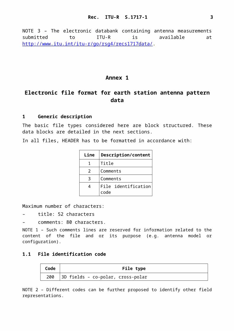
In all files, HEADER has to be formatted in accordance with:
Line Description/content
1 Title2 Comments3 Comments4 File identification code
Maximum number of characters:– title: 52 characters– comments: 80 characters.NOTE 1 – Such comments lines are reserved for information related to the content of the file and or its purpose (e.g. antenna model or configuration).

Rec. ITU-R S.1717-1 3
1.1 File identification code
Code File type
200 3D fields – co-polar, cross-polar
NOTE 2 – Different codes can be further proposed to identify other field representations.
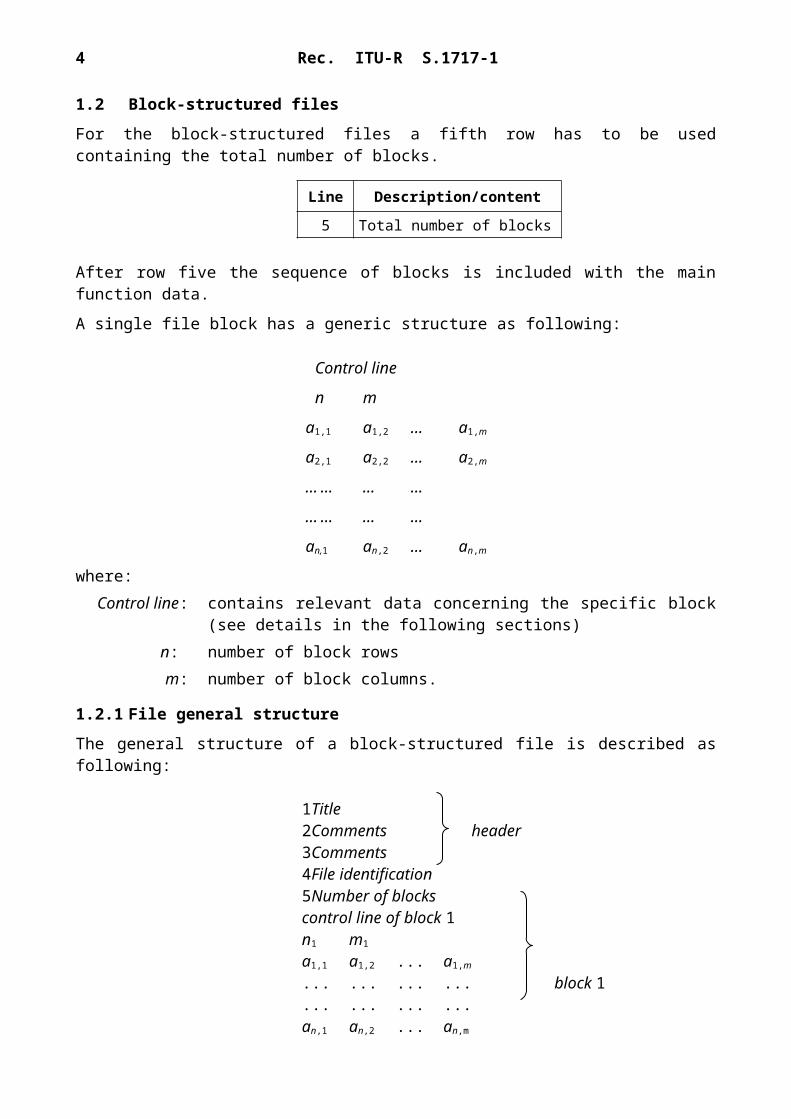
1.2 Block-structured files
For the block-structured files a fifth row has to be used containing the total number of blocks.
Line Description/content
5 Total number of blocks
After row five the sequence of blocks is included with the main function data.
A single file block has a generic structure as following:
Control line
n m
a1,1 a1,2 ... a1,m
a2,1 a2,2 ... a2,m
... ... ... ...
... ... ... ...
an,1 an,2 ... an,m
where:Control line: contains relevant data concerning the specific block (see details in the
following sections)n: number of block rowsm: number of block columns.
1.2.1 File general structure
The general structure of a block-structured file is described as following:
1Title2Comments header3Comments4File identification5Number of blockscontrol line of block 1n1 m1
a1,1 a1,2 ... a1,m
... ... ... ... block 1
... ... ... ...an,1 an,2 ... an,m
............
............

4 Rec. ITU-R S.1717-1
control line of block fnf mf
a1,1 a1,2 ... a1,mf
... ... ... ... final block
... ... ... ...anf,1 anf,2 ... anf,mf
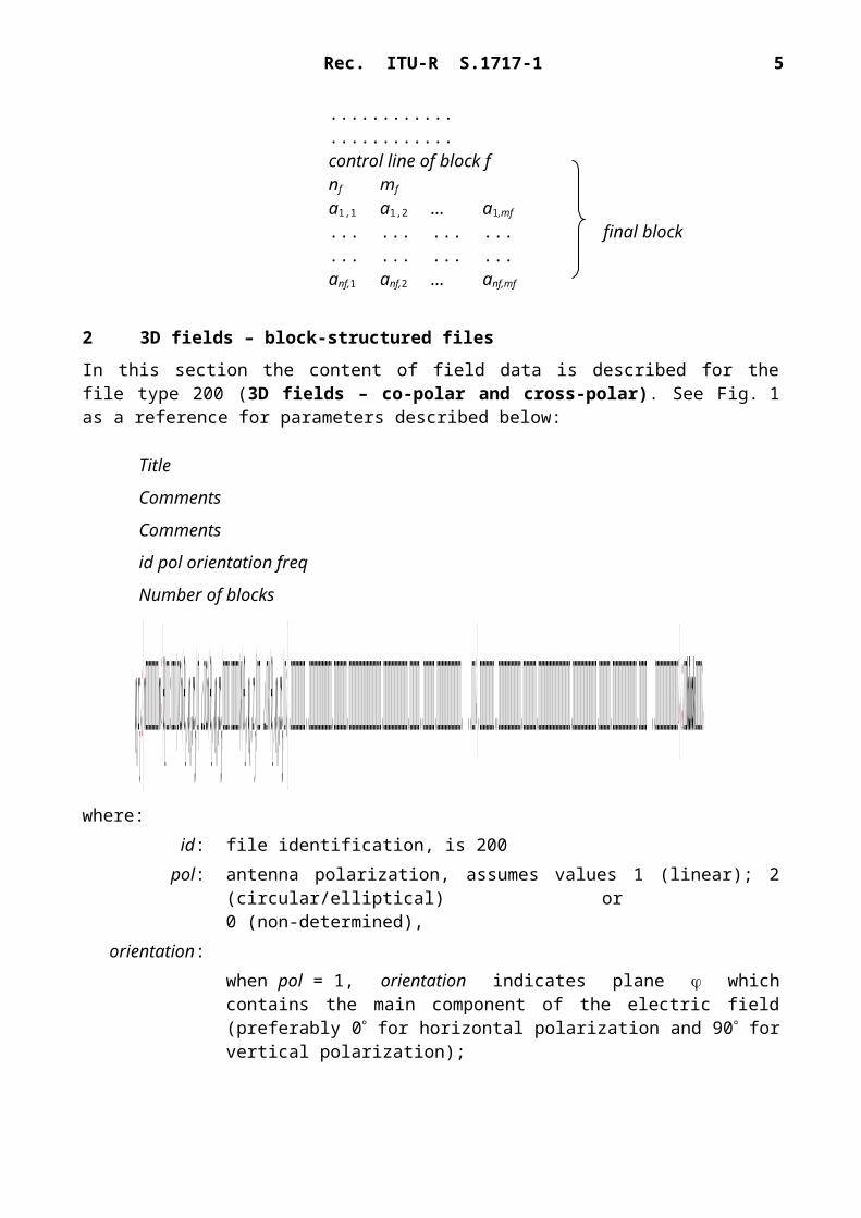
2 3D fields – block-structured files
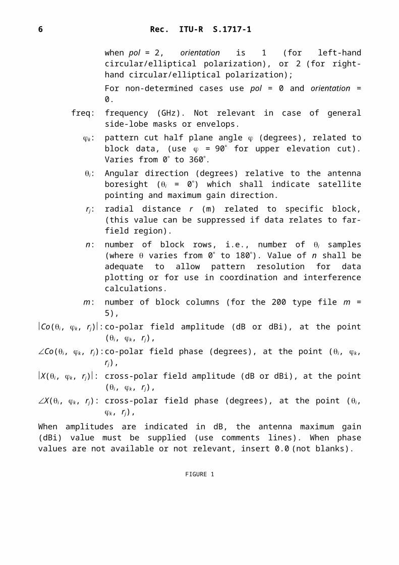
In this section the content of field data is described for the file type 200 (3D fields – co-polar and cross-polar). See Fig. 1 as a reference for parameters described below:
Title
Comments
Comments
id pol orientation freq
Number of blocks
ϕk r j ¿} n m ¿ }θ1 : | Co(θ1 , ϕk ,r j ) | ∠ Co(θ1 , ϕk ,r j ) |X (θ1 , ϕk , r j)| ∠ X (θ1 , ϕk ,r j ) ¿ } . . . . . . . . . . . .. ¿ } . . . . . . . . . . . ¿}¿¿ block ¿where:
id: file identification, is 200pol: antenna polarization, assumes values 1 (linear); 2 (circular/elliptical) or
0 (non-determined),orientation:
when pol = 1, orientation indicates plane which contains the main component of the electric field (preferably 0 for horizontal polarization and 90 for vertical polarization);when pol = 2, orientation is 1 (for left-hand circular/elliptical polarization), or 2 (for right-hand circular/elliptical polarization);For non-determined cases use pol = 0 and orientation = 0.
freq: frequency (GHz). Not relevant in case of general side-lobe masks or envelops.k: pattern cut half plane angle (degrees), related to block data, (use = 90 for
upper elevation cut). Varies from 0 to 360.i: Angular direction (degrees) relative to the antenna boresight (i = 0) which
shall indicate satellite pointing and maximum gain direction.rj: radial distance r (m) related to specific block, (this value can be suppressed if
data relates to far-field region).
Rec. ITU-R S.1717-1 5
n: number of block rows, i.e., number of i samples (where varies from 0 to 180). Value of n shall be adequate to allow pattern resolution for data plotting or for use in coordination and interference calculations.
m: number of block columns (for the 200 type file m = 5),Co(i, k, rj): co-polar field amplitude (dB or dBi), at the point (i, k, rj),Co(i, k, rj): co-polar field phase (degrees), at the point (i, k, rj),X(i, k, rj): cross-polar field amplitude (dB or dBi), at the point (i, k, rj),X(i, k, rj): cross-polar field phase (degrees), at the point (i, k, rj),
When amplitudes are indicated in dB, the antenna maximum gain (dBi) value must be supplied (use comments lines). When phase values are not available or not relevant, insert 0.0 (not blanks).
FIGURE 1Example of reflector antenna in a spherical coordinate system
as per the proposed standard file format
3 Examples
In this section a pattern data file is illustrated as an example as well as some resulting applications.
Table 1 shows some parts of the example file containing four blocks with n = 360 rows in each and representing the radiation pattern cut planes k equal to 0, 90, 180 and 270 respectively.
6 Rec. ITU-R S.1717-1
TABLE 1
Example of a measured radiation pattern file in the proposed format
Title Offset antenna XXX – 1.8 m Measured frequency 14 GHZ – EL/H – Pol H
Comments Model BO 05355
Comments Original MI – 2095 file:F:\XXX\HCOHELTX.TXT
id pol orientation freq 200 1 0 14.000Number of blocks 4
0360 5
0 46.13 132.131 –1.976 48.1830.5 42.503 119.138 3.083 –63.6
1 29.327 86.983 3.126 –48,4841.5 20.601 9.116 –5.148 –7.781
2 15.948 81.549 –23.206 86.3052.5 7.158 60.242 –17.033 89.719
...177.5 –5.305 –143.914 –34.487 –175.838
178 –5.006 –14.855 –17.404 86.68178.5 –5.433 130.715 –20.464 158.715
179 –5.928 –77.425 –29.24 –9.018179.5 –5.846 65.336 –30.317 123.385
90360 5
0 46.13 38.426 14.575 –14.0980.5 43.405 40.238 22.746 165.781
1 32.697 24.047 20.087 168.9831.5 22.179 –36.461 0.228 71.216
2 2.554 17.435 4.258 99.2392.5 15.386 –165.509 0.391 161.129
...
Figure 2 illustrates the graphical representation of the co-polar field pattern measured in the cut plane k = 0o (1st block/2nd row). In this case, this cut-plane corresponds to one side of the azimuth plane and the polarization is horizontal. In Fig. 2 a reference pattern envelope is represented based on Recommendations ITU-R S.580 and ITU-R S.465 for the co-polar pattern side-lobes.
Rec. ITU-R S.1717-1 7
FIGURE 2Co-polar field measured pattern example in the k = 0° (Az/Pol H)
Annex 2
Recommended electronic file format for receiving earth station antennapattern data when measurement data is only available in
the azimuth and elevation planes
The file type 200 described in § 2 of Annex 1 is applicable for a pattern data file with some simplifications as illustrated below by an example in Table 2:1) Radiation pattern cut planes k equal to 0 and 90 are fully sufficient assuming an
approximate symmetry of the radiation diagram that is why the pattern data files may consist of two blocks.
2) Each block may contain rows n = 200 to 220 instead of 360 when measurements cover only the angular sector from 0 to 100 (110) as the back lobes in most of the cases are not relevant.
3) Measured data relates to far-field region.4) Phase values are not relevant.
8 Rec. ITU-R S.1717-1
TABLE 2
Example of a measured radiation pattern file in the proposed format
Title Offset antenna DCE-73 – 0.7 m 0.5 m Measured frequency 11.725 GHz – Pol V
Comments Type: Single off-set system Max gain: 35.6 dBi
Comments Original file: BUL BSS antenna patterns.xls
id pol orientation freq 200 1 90 11.725Number of blocks 2
0201 5
0 0 0.0 –39.6 0.00.5 –0.7 0.0 –26.9 0.0
1 –2.7 0.0 –22.1 0.01.5 –6.2 0.0 –20.6 0.0
2 –11.5 0.0 –21.2 0.02.5 –21.6 0.0 –23.8 0.0...
98 –42 0.0 –52.8 0.0
98.5 –42.1 0.0 –54.9 0.0
99 –42.6 0.0 –50.5 0.0
99.5 –43.4 0.0 –54 0.0
100 –45.4 0.0 –54.5 0.0
90201 5
0 0 0.0 –39.2 0.00.5 –0.6 0.0 –42.5 0.0
1 –2 0.0 –52.8 0.01.5 –4.6 0.0 –54.9 0.0
2 –7.8 0.0 –53.3 0.02.5 –11 0.0 –52.9 0.0...
The submission to the databank associated to this recommendation of more recent patterns (co- and cross-polar) measured data (tabular and graphical) of small antennas with different design is important for studies on improving the reference antenna patterns for different services and frequency bands. It is advisable that the graphical representation of the co-polar/cross-polar field pattern measured in both cut planes includes the applicable reference pattern envelope. Figure 3 illustrates the graphical representation of the co-polar field pattern measured in the cut plane φk = 0 (1st block/2nd row) corresponding to the example measured data in Table 2. In Fig. 3 a reference pattern envelope is represented based on Recommendation ITU-R BO.1213.
Rec. ITU-R S.1717-1 9
FIGURE 3
______________