technology overview waste heat utilization
TRANSCRIPT

100% Klimaschutz
Technology overview waste heat utilization
COBEN

2 3
ImprintPublisher:Hochschule Osnabrück, Landkreis Osnabrück
Authors:Melanie MeyerProf. Dr.-Ing. Matthias ReckzügelSophie RotterAlexia Lescow
Translation: Jörg Krywkow
Print:Günter Druck GmbH, Georgsmarienhütte
Layout:lichtweisz .kommunikationsdesign, Dissen
Photos:fotolia
The project is funded by the European Regional Development Fund
Renewable resources in thermal energy supply 4
The future of decentralised heat utilization 5
Technologies for a decentralized use of thermal energy 7
Identification of applicable technologies 8
Direct heat utilisation 12
Heat exchangers 12
Heat accumulators 14
Heat transport 15
Indirect heat utilisation 16
Heat pump 16
Refrigerating units 17
Electricity generation 18
Activities in the district of Osnabrück 20
Partners in (waste) heat utilisation projects 22
Literature 23
Table of Contents
COBEN
4 5
Renewable resources in thermal energy supply
1 31,3 % renewable energy in gross energy consumption, 13,0 % renewable energy in end energy use of heating and cooling as well as 5,3 % in end energy use of traffic, in total this is 14,7 % renewable energy in gross energy consumption within Germany in 2015 (BMWi 2017)
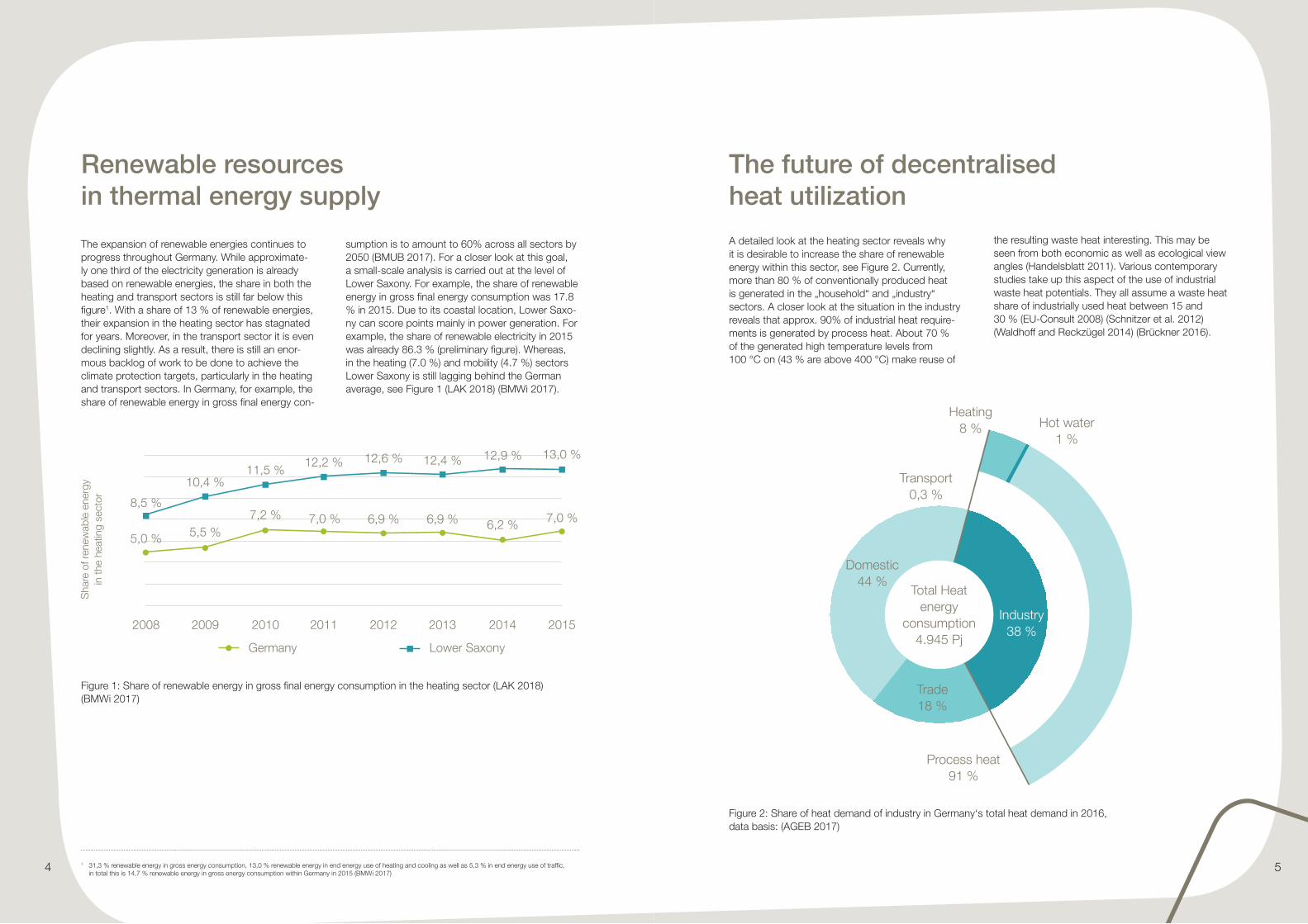
The expansion of renewable energies continues to progress throughout Germany. While approximate-ly one third of the electricity generation is already based on renewable energies, the share in both the heating and transport sectors is still far below this figure1. With a share of 13 % of renewable energies, their expansion in the heating sector has stagnated for years. Moreover, in the transport sector it is even declining slightly. As a result, there is still an enor-mous backlog of work to be done to achieve the climate protection targets, particularly in the heating and transport sectors. In Germany, for example, the share of renewable energy in gross final energy con-
sumption is to amount to 60% across all sectors by 2050 (BMUB 2017). For a closer look at this goal, a small-scale analysis is carried out at the level of Lower Saxony. For example, the share of renewable energy in gross final energy consumption was 17.8 % in 2015. Due to its coastal location, Lower Saxo-ny can score points mainly in power generation. For example, the share of renewable electricity in 2015 was already 86.3 % (preliminary figure). Whereas, in the heating (7.0 %) and mobility (4.7 %) sectors Lower Saxony is still lagging behind the German average, see Figure 1 (LAK 2018) (BMWi 2017).
The future of decentralised heat utilization
A detailed look at the heating sector reveals why it is desirable to increase the share of renewable energy within this sector, see Figure 2. Currently, more than 80 % of conventionally produced heat is generated in the „household“ and „industry“ sectors. A closer look at the situation in the industry reveals that approx. 90% of industrial heat require-ments is generated by process heat. About 70 % of the generated high temperature levels from 100 °C on (43 % are above 400 °C) make reuse of
the resulting waste heat interesting. This may be seen from both economic as well as ecological view angles (Handelsblatt 2011). Various contemporary studies take up this aspect of the use of industrial waste heat potentials. They all assume a waste heat share of industrially used heat between 15 and 30 % (EU-Consult 2008) (Schnitzer et al. 2012) (Waldhoff and Reckzügel 2014) (Brückner 2016).
Figure 1: Share of renewable energy in gross final energy consumption in the heating sector (LAK 2018) (BMWi 2017)
Germany Lower Saxony
2008 2009
5,0 % 5,5 %7,2 % 7,0 % 7,0 %
13,0 %12,9 %12,4 %12,6 %12,2 %11,5 %
10,4 %
8,5 %6,9 % 6,9 % 6,2 %
2010 2011 2012 2013 2014 2015
Sha
re o
f ren
ewab
le e
nerg
y in
the
heat
ing
sect
or
Transport 0,3 %
Heating 8 % Hot water
1 %
Process heat 91 %
Trade 18 %
Domestic 44 %
Industry 38 %
Total Heat energy
consumption 4.945 Pj
Figure 2: Share of heat demand of industry in Germany‘s total heat demand in 2016, data basis: (AGEB 2017)

6 7
Heat exchanger
Heat pump
Steam turbine
Organic Rankine Cycle
Stirling engine
Refrigeration unit
As already demonstrated in Waldhoff and Reckzü-gel (2014), a strict distinction must be made among the different qualities and levels of terminology in the determination and discussion of waste heat poten-tial. The potential which is derived from statistical data on energy consumption, is generally referred to as theoretical potential. However, the individual technologies and applications are not discussed in detail. The determination is carried out exclusively on the basis of the physical boundary conditions. As a consequence, this potential is not achievable. A more detailed look at the individual technologies reveals the technical potential. Typical technology-based data such as temperature levels, efficiency and performance ranges are taken into account. This potential can therefore be clearly influenced by the advancing development of technologies. An ad-ditional consideration of the economic feasibility of heat recovery measures results in economic potential. In addition to many other bound-ary conditions such as energy prices and interest rate developments, it is impor-tant to factor in whether the system is subject to a business or economic evaluation. According to Schnitzer et al. (2012), this potential is between 12 and 60 % of technically capabilities in general. A qualitative representation of the different potential definitions is displayed in Figure 3 (Waldhoff and Reckzügel 2014).
Technologies for a decentralized use of thermal energy
Electricity
Use of (waste) heat by providing …
Heat
Heat grids Thermal store
Cold
If energy is used locally, it is generated in the vicinity of the local consumers. Typical examples are a common supply of residential areas, e.g. by means of CHP or the utilization of industrial heat supplying heat to residential buildings or other commercial and industrial enterprises. With the latter in particu-lar, direct use of the waste heat as thermal energy is
not always economically and technically feasible. In contrast to direct use of waste heat, conversion to another form of energy or to a higher temperature level is possible. This is called indirect use of heat. In the following, the standard technologies including technical conditions and typical areas of application are briefly explained.
Regardless of all technological opportunities for the use of thermal energy, the following sequence of avoidance/utilization possibilities is recommended, in particular on the basis of economic and technical efficiency (saena 2012):
1. Reduction of waste heat;
2. Reintegration into the process;
3. Internal use;
4. Internal transformation into other forms of useful energy;
5. Sale to third parties.
direct utilization Indirect utilization
Figure 4 Technologies for direct and indirect use of thermal energy

8 9
Identification of applicable technologiesA first classification of the technologies explained below can be made using the following decision trees.
Figure 5: Decision tree for a temperature level of 50°C, data basis: (saena 2012)
(Waste) heat potential available / required
10 – 100 kW 100 kW – 1 MW
< 50°C
fluid
2.000 – 4.000 h 4.000 – 6.000 h
Heat pump
very suitable highly suitable
> 6.000 h
Figure 6: Decision tree for a temperature level of 50 to 150°C, data basis: (saena 2012)
very suitable highly suitable
(Waste) heat potential available / required
50 – 150°C
10 – 100 kW 1 – 10 MW
fluid
> 10 MW
2.000 – 4.000 h 4.000 – 6.000 h > 6.000 h
Sorption refrigerating unit In-house utilization
100 kW – 1 MW

10 11
Figure 8: Decision tree for a temperature level above 500°C, data basis: (saena 2012)Figure 7: Decision tree for a temperature level of 150 to 500°C, data basis: (saena 2012)
very suitable highly suitable
(Waste) heat potential available / required
150 – 500°C
10 – 100 kW
fluid
100 kW – 1 MW
4.000 – 6.000 h
ORC turbine Steam turbineIn-house heat utilization
External heat utilization
> 6.000 h
1 – 10 MW > 10 MW
(Waste) heat potential available / required
over 500°C
10 – 100 kW
gaseous fluid
100 kW – 1 MW 1 – 10 MW > 10 MW
4.000 – 6.000 h
ORC turbine In-house heat utilization
External heat utilization
Steam turbine
Stirling engine
> 6.000 h
12 13
Direct heat utilisation
Table 1: Typical data of various heat exchangers (saena 2012)
Type Temperature Power Media Costs
Double-pipe heat exchanger < 150 °C < 3.500 MW fluid/fluid
Finned tube heat exchanger < 300 °C < 1.000 MW gas/fluid < 15 €/kW
Shell and tube heat exchanger < 550 °C < 20 MW fluid/fluid 10 - 150 €/kW
Rotary wheel heat exchanger < 650 °C < 1,6 MW gas/gas
Heat pipe heat exchanger < 650 °C< 3 kW (je Rohr)
gas/gas
Plate heat exchanger < 750 °C < 400 MWfluid/fluidgas/gas
< 10 €/kW
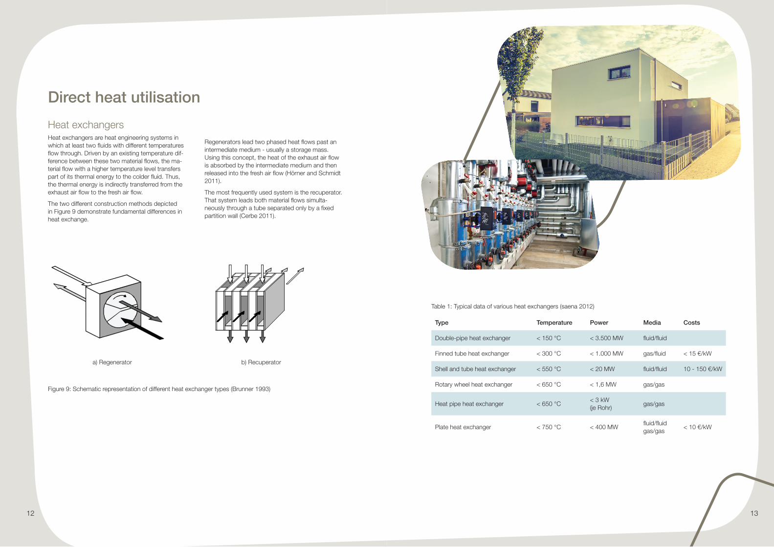
Heat exchangersHeat exchangers are heat engineering systems in which at least two fluids with different temperatures flow through. Driven by an existing temperature dif-ference between these two material flows, the ma-terial flow with a higher temperature level transfers part of its thermal energy to the colder fluid. Thus, the thermal energy is indirectly transferred from the exhaust air flow to the fresh air flow.
The two different construction methods depicted in Figure 9 demonstrate fundamental differences in heat exchange.
Regenerators lead two phased heat flows past an intermediate medium - usually a storage mass. Using this concept, the heat of the exhaust air flow is absorbed by the intermediate medium and then released into the fresh air flow (Hörner and Schmidt 2011).
The most frequently used system is the recuperator. That system leads both material flows simulta-neously through a tube separated only by a fixed partition wall (Cerbe 2011).
Figure 9: Schematic representation of different heat exchanger types (Brunner 1993)
a) Regenerator b) Recuperator

14 15
Heat transport
Table 3: Overview of various types of heating networks (C.A.R.M.E.N. 2018)
Type Temperature Excess pressure
Hot water < 100 °C 4-10 bar
Low-pressure hot water 70-120 °C 4-6 bar
High-pressure hot water 120-180 °C 6-20 bar
High pressure steam network 120-160 °C 2-15 bar
Heat networks are used to transport thermal energy from a heat source to a heat sink. Water is usually used as the transportation medium. Infrequently, it may be steam (approx. 3 % of the heating net-works) (AGFW 2017). The heat that cannot be used internally at a source is transferred to the carrier medium flowing through the heat network by means of heat exchangers. There, the energy is again par-tially extracted from the carrier medium by means of additional heat exchangers and transferred to an
Table 2: Typical data of different heat accumulators (saena 2012)
Type Temperature Power Size Storage capacity
Storage density
Costs
Sensible heat store
> 1.000 °C > 100 MW > 10.000 m³ > 100 MWh < 100 kWh/m³
Latent heat accumu-lator
< 0 - > 400 °C < 17 m³ (demons-trated)
< 2,5 MWh (demons- trated)
< 150 kWh/m³ (demons- trated)
10-50 €/kWh
Sorption heat store
> 1.000 °C < 50 m³ (demons- trated)
< 4,5 MWh (demons- trated)
< 185 kWh/m³ (demons- trated)
8-100 €/kWh
Heat accumulatorsHeat accumulators enable operators to decouple processes of heat supply and dissipation. In this way it is possible to deploy irregular or staggered heat sources for heat utilization. Heat accumulators are also differentiated on the basis of their functio-nality of heat storage. Currently, these devices are mainly used to store sensitive or latent heat. Both storage types require a higher temperature of the waste heat generated than the storage tempera-ture. In addition, the storage temperature must be higher than the temperature available for applica-tions.
Nowadays, sensible heat accumulators are the most common variant for storing thermal energy. For example, they are used as typical hot water accumulators often found in smaller designs in resi-dential buildings or as intermediate accumulators in local heating networks.
Latent heat accumulators, on the other hand, make use of the enthalpy of reversible state changes (heat of transformation) for heat storage. Thus, heat is usually absorbed or released during the phase change between solid and liquid at a constant tem-perature level, see Figure 10 (saena 2016) (Schel-long 2016).
To date, this type of storage technology is used, for example, in building architecture. Many people are familiar with this type of heat storage in the form of pocket heaters. Large facilities are currently still under development (energy2.0 2012) (Blesl et al. 2010).
Regardless of the storage type, the storage cycles should be kept as short as possible from an eco-nomic point of view. Theoretically, however, it would also be possible to store the waste heat during the summer and use it in winter, for example saena (2016).
internal cycle of the heat sink. The cooled transfer medium then flows back through a return line, and the loop starts again.
In many places the use of mobile latent heat accu-mulators is planned. This may be compared to the shape of a tanker truck, see e.g. Wunder (2016) and Walter (2017). Already in 2011, this technology was applied economically within a radius of 30 km. (Petersen 2011).
sensibleheat
latent heat
Tem
per
atur
e
heat quantity stored
Figure 10: Functional principle of latent heat accumulators

16 17
Table 4: Typical data of different heat accumulators (saena 2012)
Type Temperature of heat medium
Power Heat carrier
Performance coefficient
costs
Compression heat pump
< 50 °C 15 kW-20 MW air, fluid 3,0-5,0 150-1.500 €/kWth
Absorption heat pump
< 200 °C 15 kW-20 MW fluid 1,4-2,2 500-1.200 €/kWth
Adsorption heat pump
< 90 °C 7,5-500 kW fluid 1,3-1,6 1.500 €/kWth
Refrigerating unitsThe technologies for providing cooling by means of refrigeration machines and heat supply by means of heat pumps are based on an identical design. While in heat pumps the useful capacity of the condenser (heating capacity) is transferred to the consumer, in refrigerating machines, however, the useful capacity of the evaporator (cooling capacity) is transferred to the consumer.
A main distinction is made between ammonia water and water/lithium bromide in the work equipment used. Water/lithium bromide plants achieve coo-ling temperatures of up to +5 °C. Ammonia-water plants achieve a cooling temperature of up to -10 °C. (saena 2016) (Schmid et al. 2016).
Table 5: Typical data of various plants for temperature reduction of thermal energy
Type Temperature of heat medium
Power Heat carrier Perfor-mance coefficient
Costs
Absorption refrigerating units
<70 °C 5 kW-12 MW fluid, steam 0,5-0,8 200-1.250 €/kWth
Adsorption refrigerating units
55-100 °C 5-350 kW fluid 0,6-0,7 300-1.500 €/kWth
Indirect heat utilisation
Heat pumpHeat pumps offer an opportunity to increase the temperature level of the heat flows by means of ad-ditional electrical energy supply. Hence, they enable an upgrading of low-temperature heat. Basically, the smaller the temperature difference between waste heat and useful heat, the more effectively such a pump can work. The efficiency, which is referred to as the COP (Coefficient of Performance), indica-tes the ratio between the useful heat flux and the electrical power used (drive power). Based on their design, heat pumps can be divided into compressi-on- and sorption-based heat pumps.
Compression heat pumps use supplied energy to drive a compressor, which in turn increases the pressure level of the working medium. These heat pumps can be operated with electrical energy as well as with natural gas or diesel fuel. This tech-nique results in a temperature increase of approx. 40 to 50 K. As a result, a multiple of the power de-ployed is available as usable heat output. The gain emerges from extracted ambient heat (saena 2016).
Sorption heat pumps (absorption and adsorption heat pumps), unlike compression heat pumps, have a thermal drive rather than a mechanical one. Thus, these devices generate higher-temperature heat by
means of the available waste heat. Absorption heat pumps are usually driven by fossil fuels, biomass or waste heat. Whereas, adsorption heat pumps are powered by means of combinations of materials such as silica gel/ zeolites and water or ammonia and water. Due to their low maintenance require-ments, absorption heat pumps are already used in industrial waste heat utilisation (saena 2016).
Figure 11: Schematic diagram of a heat pump
Figure 12: Schematic diagram of a refrigerating unit
Heat source
Compressor Expansion valve
Evaporator
Condenser
Heat sink
Surrounding
Compressor Expansion valve
Evaporator
Condenser
Cold cell

18 19
Electricity generation
Another way of using excess heat is to convert it into electricity. The use of electricity can be carried out both for own consumption and by feeding it into the power grid.
In the steam process (Clausius Rankine Cycle), a turbine is driven by water as the working medium. Since water as a working medium requires high temperatures and high thermal capacities, there are hardly any applications for this in industrial waste heat utilisation. The main area of application for this standardized process is in conventional thermal power plants (Grote, Hoffmann and Tänzer 2015).
In contrast to the Clausius Rankine cycle, the Orga-nic Rankine Cycle (ORC) uses organic substances such as butane, pentane or silicone oils. These all have a lower boiling point than water and can therefore be deployed at a lower temperature level. (Grote, Hoffmann and Tänzer 2015) (Köhler 2005)
The principle of the Stirling engine is based on the properties of some working media to expand with heat. In an enclosed working area the working medium is alternately compressed or expanded within a cycle process of a piston. Typical areas of application for Stirling engines are solar thermal and biomass applications. (Waldhoff and Reckzügel 2014)
Table 6: Typical data of various plants for the conversion of thermal into electrical energy (Grote, Hoffmann and Tänzer 2015) (saena 2012)
Type Temperature of heat medium
Power Heat carrier Efficiencyt Costs
Steam process
> 150 °C > 20 kWel fluid, steam, gas
< 10 % < 5.000 €/kWel
ORC > 110 °C 30 kWel-3 MWel fluid, steam, gas
5-15 % 3.000-7.500 €/kWel
Stirling engine
650-1.100 °C 30kWel-300 MWel exhaust gas 10-16 % 1.400-1.700 €/kWel
Figure 13: Schematic representation of thermal energy into eletrical energy
Heat source
Feed water pumpTurbine
Condenser
Generator
Steam generator
Heat source
Pump
TurbineGenerator
Condenser
Evaporator
a) CRC process b) ORC process
G G

20 21
Activities in the district of OsnabrückThe district of Osnabrück recognised the poten-tial of heat utilization, especially industrial waste heat utilisation, early on. In 2012, the district and neighbouring towns and districts became master plan municipalities in the federal „Master Plan 100% Climate Protection“ programme. In this way they opened up to the future-oriented field of climate protection. In this context, the use of waste heat has been defined as a key topic. Starting with a structural analysis of the district of Osnabrück and the development of a heat register for energy-intensive industries as part of the study „ReWIn - Regional Heat Register Industry“, the planning portal „PInA - Planning Portal Industrial Waste Heat“ was developed on this basis. Building on this, one of the main objectives of „COBEN - Delivering Community Be-nefits of Civic Energy“ is the identification of hot spots as well as their develop-ment and implementation planning. In recent years a gradual process has advanced in the district. The respective projects have continuously received scientific supervision by the Hochschule Os-nabrück and the Energy Competence Centre:
2013 2014 2015 2016 2017 2018 2019
ReWIn PINA
COBEN
Figure 14: Map of the district of Osnabrück
Figure 15: Activities in the main area of waste heat utilization (Waldhoff and Reckzügel 2014) (LK Osnabrück 2017) (McGovern 2018)

22 23
Partners in (waste) heat utilisation projects Although every local energy situation including its framework conditions is special (e.g. waste heat or other forms of energy might be used externally) and must be seen as an individual case, the contacts are always similar. The implementation of such a project requires a structure from which all partici-pants feel adequately represented. Usually, a small number of strong personalities initiate and bundle opinions and activities. The local government as an independent, central institution is always an important contact. The district of Osnabrück and its Climate Initiative Team are in an excellent strate-gic position. In this way, long-term strategies are developed and tangible, implementable projects are initiated. At the same time the involved enterprises themselves can pursue their core business undis-turbed. For example, the expertise required for this endeavour is provided by energy suppliers, planning offices and the scientific community. Yet, they can be consulted for specific questions (Energie-Strate-gierat Weser-Ems (Hrsg.) 2017).
LiteratureAGEB: Anwendungsbilanzen für die Endenergiesektoren in Deutschland in den Jahren 2013 bis 2016. Berlin. AG Energiebilanzen e.V., 2017.
AGFW: AGFW - Hauptbericht 2016. Frankfurt am Main. Arbeitsgemeinschaft Fernwärme, 2017.
Blesl, M., M. Ohl, U. Fahl et al.: Ganzheitliche Bewertung innovativer mobiler thermischer Energiespeicherkonzepte für Baden-Württemberg. Stuttgart, 2010.
BMUB: Klimaschutz in Zahlen. Fakten, Trends und Impulse deutscher Klimapolitik. Berlin. Bundesministerium für Umwelt, Naturschutz, Bau und Reaktorsicherheit, 2017.
BMWi: Zeitreihen zur Entwicklung der erneuerbaren Energie in Deutschland. Unter Verwendung von Daten der Ar-beitsgruppe Erneuerbare Energien-Statistik (AGEE-Stat). Berlin. Bundesministerium für Wirtschaft und Energie, 2017.
Brückner, S.: Industrielle Abwärme in Deutschland - Bestimmung von gesicherten Aufkommen und technischer bzw. wirtschaftlicher Nutzbarkeit. Dissertation, Technische Universität München, 2016.
C.A.R.M.E.N.: Biogene Festbrennstoffe - Wärmenetze. Netzstrukturen, Netztypen. Edited by Centrales Agrar-Rohstoff Marketing- und Energie-Netzwerk e.V. 2018. https://www.carmen-ev.de/biogene-festbrennstoffe/waermenetze/2038-netzstrukturen-netztypen (accessed 01.29.2018).
Cerbe, G., Wilhelms G.: Technische Thermodynamik. 16., akt. Auflage. München. Carl Hanser Verlag, 2011.
Energie-Strategierat Weser-Ems (Hrsg.): Innovationen aus Weser-Ems, 2017.
energy2.0: Effiziente Energieversorgung durch Abwärme. energy2.0.net Fachmagazin, April 2012: p. 10 ff.
EU-Consult: Abwärmenutzung in Kommunen. Augsburg. Bayerisches Landesamt für Umwelt, 2008.
Grote, L., P. Hoffmann and G. Tänzer: Abwärmenutzung - Potenziale, Hemmnisse und Umsetzungsvorschläge. Saar-brücken. IZES gGmbH (Institut für ZukunftsEnergieSysteme), 2015.
Handelsblatt: Nutzung der Prozesswärme in der europäischen Industrie nach Temperaturen (in Prozent). https://de.statista.com/statistik/daten/studie/190224/umfrage/prozesswaerme-temperaturen-in-der-europaeischen-industrie (accessed 03.21.2018).
Hörner, B. and M. Schmidt (Hrsg.): Handbuch der Klimatechnik. 5., überarb. und erw. Auflage. Vol. Band 2: Anwen-dungen. Berlin. VDE Verlag, 2011.
Köhler, S.: Geothermisch angetriebene Dampfkraftprozesse - Analyse und Prozessvergleich binärer Kraftwerke. Ber-lin. Technische Universität Berlin, 2005.
LAK: Anteil erneuerbarer Energieträger am Bruttoendenergieverbrauch. Edited by Länderarbeitskreis Energiebilanzen. Länderarbeitskreis Energiebilanzen. 16.02.2018. http://www.lak-energiebilanzen.de/anteil-erneuerbarer-energietrae-ger-am-bruttoendenergieverbrauch/ (accessed 03.07.2018).
LK Osnabrück: PInA - Das Portal für industrielle Abwärme. https://lkos.maps.arcgis.com/apps/webappviewer/index.html?id=bcc0492c6b504520bb9b4aa4ac4ded56 (accessed 03.21.2018).
McGovern, G.: COBEN - Making Civic Energy Work. https://civic-energy.eu/regions (accessed 03.21.2018).
Petersen, K.: Wärme auf Rädern verbindet Erzeuger und Nutzer. Holz Zentralblatt, no. 10 (2011): p. 254 f.
saena: Technologie der Abwärmenutzung. Dresden. Sächsische Energieagentur, 2016.
saena: Technologie der Abwärmenutzung. Dresden. Sächsische Energieagentur, 2012.
Schellong, W.: Analyse und Optimierung von Energieverbundsystemen. Berlin Heidelberg. Springer, 2016.
Schmid, C., T. Baumgartner, J. Nipkow, C. Vogt and J. Willers. Heizung / Lüftung / Elektrizität. Energietechnik im Gebäude. 5., überarb. und akt. Aufl. Zürich. vdf Hochschulverlag AG an der ETH Zürich, 2016.
Schnitzer, H., J. Schmied, M. Titz, P. Jägerhuber, C. Enzi and P. Filzwieser: Abwärmekataster Steiermark, Endbericht Projekt des Landes Steiermark. Graz. Technische Universität Graz, 2012.
Waldhoff, C., and M. Reckzügel: ReWIn - Regionales Wärmekataster Industrie. Strategieentwicklung für die systema-tische Optimierung der Abwärmenutzung in Industrie und Gewerbe. Osnabrück. Hochschule Osnabrück, 2014.
Walter, F.: Bald rollt es warm durch Altwarmbüchen. Edited by Hannoversche Allgemeine. Isernhagen, 27. 07.2017.
Wunder, T.: Ein Lastwagen liefert Wärme. Edited by Augsburger Allgemeine. Landkreis Landsberg, 22.11.2016.
