technological attraction poles
TRANSCRIPT

Technological Attraction Poles
J-P Kruth Katholieke Universiteit Leuven
T. Dormal
C.R.I.F. – W.T.C.M., division Rapid Prototyping
P. Rochus Centre Spatial de Liège
FINAL REPORT
RAPID PROTOTYPING & MANUFACTURING FOR SPACE COMPONENTS
PA/32

Belgian Science Policy Rue de la Science 8 Wetenschapsstraat 8 B-1000 Brussels Belgium Tel: +32 (0)2 238 34 11 – Fax: +32 (0)2 230 59 12 http://www.belspo.be Contact person: Mr. Dimitri Harmegnies Secretariat: +32 (0)2 238 37 61 Neither the Belgian Science Policy nor any person acting on behalf of the Belgian Science Policy is responsible for the use which might be made of the following information. The authors are responsible for the content.
No part of this publication may be reproduced, stored in a retrieval system, or transmitted in any form or by any means, electronic, mechanical, photocopying, recording, or otherwise, without indicating the reference.

Project PA/32 - « Rapid prototyping & manufacturing for space components »
Technological Attraction Pole 3
Contents
NOMENCLATURE 4
ADMINISTRATIVE REPORT 5
Katholieke Universiteit Leuven (K.U.Leuven) 5
Centre de Recherche des Industries de Fabrication (C.R.I.F.) 6
Centre Spatial de Liège (C.S.L.) 7
ACTIVITIES REPORT 9
Context 9
Objectives 10
Methodology and results 10 Task 1: Needs, requirements, initial specifications 10 Task 2: Testing applicability of RM parts in orbit conditions 11 Task 3: Improvement of the resolution and surface quality in Stereolithography 13 Task 4: Improvement of Optoform for space components 14 Task 5: Developments of SLS techniques for space components 15 Task 6: Porous or hollow light-weight components or parts with gradient properties 20 Task 7: Jet-based RP technologies 23 Task 8: Deposition of masks or pattern on a substrate 26 Task 9: RP/RM technologies to produce optical components 26 Task 10: Case studies 27 Task 11: Dissemination of results and guidelines 36
Summary 37
References 39
NETWORK AND USERS’ COMMITTEE 40
PUBLICATION AND VALORISATION 41

Project PA/32 - « Rapid prototyping & manufacturing for space components »
Technological Attraction Pole 4
Nomenclature
CAD Computer Aided Design CAM Computer Aided Manufacturing CNC Computer Numerical Controlled C.R.I.F. Centre de Recherche de l’Industrie Fabrimetallurgique C.S.L. Centre Spatial de Liège CVCM Collected Volatile Condensed Material ECSS European Cooperation for Space Standardisation MM Man Months RM Rapid Manufacturing RP Rapid Prototyping RPD Rapid Product Development SLA Stereolithography SLM Selective Laser Melting SLS Selective Laser Sintering T.A.P. Technological Attraction Poles TML Total Mass Lost VCM Vacuum Chamber Measurement W.T.C.M. Wetenschappelijk en Technisch Centrum van de Metaalverwerkende
Nijverheid

Project PA/32 - « Rapid prototyping & manufacturing for space components »
Technological Attraction Pole 5
Administrative Report
Katholieke Universiteit Leuven (K.U.Leuven)
Co-ordinator Contract no.: PA-01-321 Division Production Engineering, Machine Design, and Automation Celestijnenlaan 300 B B-3001 Heverlee Tel. +32.16.32.24.80 Fax +32.16.32.29.87 Contact: Prof. J.-P. Kruth ([email protected]) List of Personnel on payroll of the project VAN ELSEN Maarten
Nationality: Belgium Function: Researcher Type of contract: scholarship Terms of contract: Employment: 100% Time spent on TAP: 27 MM on payroll
MERCELIS Peter Nationality: Belgium Function: Researcher Type of contract: scholarship Terms of contract: Employment: 100% Time spent on TAP: 7 MM on payroll, 6 MM not on payroll
GILIO Michel Nationality: Belgium Function: Researcher Type of contract: scholarship Terms of contract: Employment: 100% Time spent on TAP: 7 MM on payroll, 12 MM not on payroll Financed by (source): K.U.Leuven
List of Personnel not on payroll, but working for the project KRUTH Jean-Pierre
Nationality: Belgium Function: Full professor Type of contract: ZAP Terms of contract: Employment: 100% Time spent on TAP: 2 MM

Project PA/32 - « Rapid prototyping & manufacturing for space components »
Technological Attraction Pole 6
Financed by (source): K.U.Leuven VAN VAERENBERGH Jonas
Nationality: Belgium Function: Researcher Type of contract: scholarship Terms of contract: Employment: 100% Time spent on TAP: 8 MM Financed by (source): K.U.Leuven
Centre de Recherche des Industries de Fabrication (C.R.I.F.)
Contract no.: PA-B2-322 CRIF (Centre de Recherche des Industries de Fabrication) Liege Science Park 12, rue du Bois saint Jean B-4102 Seraing Tel: +32.4.361.87.60 Fax: +32.4.361.87.02 Contact: Thierry Dormal ([email protected]) List of Personnel on payroll of the project DORMAL Thierry
Nationality: Belgium Function: head of department Type of contract: employee Terms of contract: 01-01-2003 – 31-12-2005 Employment: 100% Time spent on TAP: 3 MM
CARRUS Raoul Nationality: Belgium Function: Project Manager Type of contract: employee Terms of contract: 01-01-2003 – 31-12-2005 Employment: 100% Time spent on TAP: 7 MM
TROUSSE Xavier Nationality: Belgium Function: Project Manager Type of contract: employee Terms of contract: 01-01-2003 – 31-12-2005 Employment: 100% Time spent on TAP: 16.5 MM
ANELLI Mario Nationality: Belgium Function: Senior technician

Project PA/32 - « Rapid prototyping & manufacturing for space components »
Technological Attraction Pole 7
Type of contract: employee Terms of contract: 01-01-2003 – 31-12-2005 Employment: 100% Time spent on TAP: 4 MM
List of Personnel not on payroll, but working for the project CAMBIER Frédérik
Nationality: Belgium Function: Project Manager Type of contract: employee Terms of contract: 01-10-2003 – 31-01-2005 Employment: 100% Time spent on TAP: 3 MM
Centre Spatial de Liège (C.S.L.)
Contract no.: PA-12-323 Université de Liège Centre spatial de Liège Avenue de Pré Aily B-4031 Angleur Tel: +32.4.367.66.68 Fax: +32.4.367.56.13 Contact: Dr. Ing. P. Rochus ([email protected]) List of Personnel on payroll of the project ROCHUS Pierre
Nationality: Belgium Function: Director of R&D Type of contract: employee Terms of contract: 01-01-2003 – 31-12-2005 Employment: 100% Time spent on TAP: 6 MM
DEFISE Jean-Marc
Nationality: Belgium Function: Head of Department Type of contract: employee Terms of contract: 01-01-2003 – 31-12-2005 Employment: 100% Time spent on TAP: 3 MM
PLESSERIA Jean-Yves
Nationality: Belgium Function: Engineer Type of contract: employee Terms of contract: 01-01-2003 – 31-12-2005 Employment: 100% Time spent on TAP: 8 MM

Project PA/32 - « Rapid prototyping & manufacturing for space components »
Technological Attraction Pole 8
JACQUEMART Thierry
Nationality: Belgium Function: Technician Type of contract: employee Terms of contract: 01-01-2003 – 31-12-2005 Employment: 100% Time spent on TAP: 3 MM
List of Personnel not on payroll, but working for the project None

Project PA/32 - « Rapid prototyping & manufacturing for space components »
Technological Attraction Pole 9
Activities Report
Context
Single component manufacturing is a typical need in the spatial sector where parts are generally needed in series of one or a few items (typically 2 or 3), making the classical manufacturing techniques – like injection moulding, investment casting or five-axis milling of free-form shapes – unsuited or prohibitively expensive (prohibitive cost of moulds and dies, unaffordable CNC programming cost, etc.). Rapid Manufacturing (RM) is an emerging technology offering solutions to this manufacturing problem. RM applies RP techniques to produce real functional components rather than prototypes. The aim is that the resulting layer-manufactured RM-parts are made from real engineering materials having the same or quite similar properties than the bulk engineering materials used in traditional manufacturing, even though they are obtained in a different way (e.g. starting from liquid or powder material, produced via intermediate states involving a sacrificial polymer binder phase or requiring a post-treatment to obtain the aimed final material properties). Today, the pallet of available RM processes and materials is still limited and quite some research and development is still required to extend this technology to typical aerospace materials (e.g. Ti, Al, ceramics and composites). Prototypes are an essential need in the development of systems, instruments and components for satellites and launchers. During the last decade new techniques emerged that allow fast, accurate1 and automated production of prototypes starting from a 3D CAD model of the part or component. Those techniques, known as Rapid Prototyping (RP), build up the prototype layer after layer by creating or stacking successive 2D layers of material above each other. This allows the production of quite complex parts (free-form parts, parts with intricate internal geometries) since the complex 3D geometry is decomposed in a succession of simple 2D geometries or layers. Although RP techniques originally aimed at producing prototypes in polymer-like materials with limited mechanical, thermal or optical properties, recent developments enlarged the application to the production of prototypes in other materials (e.g. technical polymers like nylon, metals like bronze or steel). However, the available material pallet is still quite limited and not tuned towards aerospace requirements. These prototypes could be used as breadboard to define the interfaces on the spacecraft, to define the cabling and to define the thermal blankets. Besides the technical issues of producing prototypes and functional one-off parts in a fast and efficient way, a lot remains to be done in mastering those technologies and integrating it in a spatial product development cycle. This calls for the application of Rapid Product Development methodologies (RPD) in the aerospace sector. This in turn calls for the application of special software tools for design (CAD) and manufacturing (CAM). Dedicated RP/RM CAD/CAM software packages exist on the market. Those software packages are either generic tools (e.g. CAD-to-STL file converters/generators and ‘repair’ software, reverse engineering software) or dedicated software packages (e.g. ‘rapid tooling’ software for rapid manufacturing of moulds and dies). There is a lack of experience in using and adapting or tuning those software tools for aerospace applications.
1 Accurate as compared to prototypes that are produced manually.

Project PA/32 - « Rapid prototyping & manufacturing for space components »
Technological Attraction Pole 10
Objectives
This project aims to provide a major contribution to the development of generic technologies for the development/production of prototypes of systems, instruments and component for satellites and launchers. Besides, the project will be a major stimulus to establish a network of organisations (K.U.Leuven, CRIF, CSL) and industries (AMOS, OIP, Verhaert, Materialise, Sonaca, Techspace Aero, Sabca and Lambda X) that will share their needs, requirements and solutions in the domain of RP, RPD and RM for spatial applications. The technical objective is to borrow generic technologies from the domain of ‘rapid prototyping’ (RP), ‘rapid product development’ (RPD) and ‘rapid manufacturing’ (RM) and to apply, adapt and further develop these technologies to make them applicable to the development and fabrication of prototypes and components for the spatial sector.
Methodology and results
The activities presented below refer to the tasks that were scheduled during the project (01-01-2003 till 31-12-2005). For a complete overview of all results concerning material properties, technological limitations, design rules etc. we refer to the separate ‘guidelines for RP/RM in aerospace’ that are written in the scope of this project (see task 11).
Task 1: Needs, requirements, initial specifications
Meetings with space hardware designers have confirmed that RP/RM is of high interest for space applications. The difficulties for the introduction of these methods in space design are not only the technical problems but also the lack of information. That is why the dissemination of the guidelines is of huge importance. Thanks to exchange with the partners and with the users’ committee, we have a better idea of the specific needs for the future of RM/RP. This has been a driving factor throughout the project. The first technical difficulty is the choice of materials. Even today, most of the materials used for RP/RM are polymers and infiltrated metallic parts to a lesser extent. The real commercialisation of equipment for single component metallic powders starts around 2003. The first machine available of this kind in Belgium was a Concept Laser M3Linear at K.U.Leuven, installed in December 2004. The processing of Titanium and Aluminium alloys on such equipment is feasible, but not yet commercial. The processing of ceramics has not outgrown research institutes. As a result, materials are generally not well known while a complete knowledge of the material is generally mandatory in space hardware. Not only knowledge is important, also having the same properties as obtained by conventional machining is advantageous. It has been emphasised during the meetings that aluminium and titanium remain the baseline materials for space structures, in order to orient the development towards these materials. A second technical point is the accuracy of the manufacturing processes. It appears that the baseline accuracy of RP/RM is of the order of 0.1 mm. Thus, it is clear that in some cases, RM/RP must be combined with conventional machining to achieve requirements when high accuracy is required.

Project PA/32 - « Rapid prototyping & manufacturing for space components »
Technological Attraction Pole 11
Pore and crack free parts are also needed if the component is structural. Large metallic parts, produced with RP/RM, often suffer from micro-cracks due to thermal stresses. Pores are an issue, but with the latest RP/RM techniques, it is possible to reduce the amount of pores to a level comparable with cast parts. Milling of cast or forged semi-manufactured parts is the main production method for most metallic components in aerospace. A last issue is the certification of the manufacturing process. Since space industry is very demanding, the repeatability of the process must be improved. However, this is not easily achieved in a research environment. Therefore, the focus lies on the less demanding parts. Another difficulty in the project is that every application is unique, not only in terms of part geometry, but also in terms of material properties, accuracy etc. A first designer only needs a polymer prototype to use in a mock-up. Technical specifications are less demanding. Another one wants a critical part in Ti-6Al-4V, with full density and no cracks. Someone else wants a part with a very high accuracy for an optical component, preferable in aluminium 7075. For a part that must be capable of withstanding high temperatures, a ceramic part is asked for. For the cooling of satellite components, a stainless steel part is needed with very thin walls and no porosity. Etc. Because of the limited capacity in the project, it was not possible to fulfil all demands from all members of the users’ committee. This also implies that some tasks were not performed. Improving all technologies for the high demands of the users was, unfortunately, not feasible.
Task 2: Testing applicability of RM parts in orbit conditions
One of the major requirements for material selection in space is the European norm ECSS-Q-70-02A that defines the maximum outgassing2 rate per quantity of material. A test is defined (µVCM test) that consists in heating at 125°C a sample of the material under vacuum during 24 hours. The relative variation of mass (TML) has to be lower than 1 %. A collector at 25°C is also included in the vacuum chamber to collect the outgassed material. This allows the measurement of collected volatile condensed material (CVCM). The CVCM has to be lower than 0.1 %. Conditioning phases in a controlled environment surround this heating phase. A typical graph, resulting from such µVCM test is given in Figure 1.
2 Outgassing refers to the fact that components loose part of their mass when being in vacuum for a longer period of time.

Project PA/32 - « Rapid prototyping & manufacturing for space components »
Technological Attraction Pole 12
time
TMLRML
24 h 48 h 72 hConditionning Outgassingunder vacuumand at 125°C
Conditionning
CVCM
Sample m
assR
ecuperatorm
ass
Figure 1: Typical graph from an outgassing test
This test has been performed by CSL on different samples provided by CRIF and KUL. The available facilities in CSL are not sufficient to conclude to a real qualification of the material but give a good estimation and allow performing a pre-selection. A blank test has been performed to verify the cleanliness of the vacuum chamber. The samples tested are ToolingB, Watershed, Polyamid, Injected polyamide, Waterclear, Nylon GF sand blasted, bronze infiltrated stainless steel (prometal) and SiC. For Watershed, the procedure has been adapted due to the fact that the maximum allowed temperature for watershed is around 60°C. Therefore, the heating temperature has been limited to 50°C but the duration has been increased to 5 days. This material was out of specification (mainly because of its low maximum authorised temperature not compatible with standard testing). It has been decided that some of these samples would be sent to ESA laboratory in ESTEC for a complete outgassing qualification. The chosen samples are: ToolingB, Polyamide PA 2200, Polyamide PA 2200 impregnated with epoxy resin and sintered SiC nanopowder. A report has been received in June 2004 and was made available for the partners and users’ committee. The conclusion is full acceptance for Polyamide, ToolingB and SiC Nanopowder and marginality for impregnated polyamide, meaning that it is accepted in certain conditions (mentioned in ECSS-Q-70-02A standard). It has to be pointed out that in some conditions (optical systems), these materials would not be preferred because of relatively high outgassing values. It has nevertheless been observed that there is quite a difference in the numerical values between CSL measurements and ESTEC measurements. This can be due to CSL procedure that is simplified in terms of sample size and test laboratory conditions. A second kind of tests that is performed is cryogenic resistance. A known phenomenon when cooling sintered powder down to liquid helium temperature is a loss of integrity and a return to powder state. A test has been performed on sintered SiC and was successful. Some components were also subjected to vibration tests (see task 10).

Project PA/32 - « Rapid prototyping & manufacturing for space components »
Technological Attraction Pole 13
Task 3: Improvement of the resolution and surface quality in Stereolithography
Most of the work is done in the field of curtain recoating systems, a so-called ‘pre-metered recoating system’. This method increases the recoating speed dramatically (to 1.5 m/s), compared to commercial scraper-like systems, and has the advantage of having no shear stresses in the deposited layer. Furthermore, controlling the layer thickness is easy by setting the pump flow rate and the speed of the coating die to specified values. The major drawback is the bubble formation in the deposited layer. One of the most important parts is the curtain recoating die. A slot type die is chosen, because of the higher performance in SLA. Such dies have a constant section. The die has some constraints concerning symmetry, because the deposition should work in two directions. Simulations of the fluid flow reveal the importance of several parameters. A new curtain recoating die was developed and installed successfully. The performance of the die is expressed in terms of a uniformity index UI. The uniformity index is defined as the ratio of the difference of maximum and minimum efflux to the average efflux. For the newly developed curtain recoating die, the UI is measured experimentally to be about 5%. This is acceptable for SLA. Another issue is the stability of the liquid curtain. A stable curtain restores deflections. Anti-symmetrical waves are absolute unstable at low Weber numbers. This adds some constraints to the system. Because air is trapped in front of the curtain, the dynamic behaviour of the system is slower than without air. To solve this problem, curtain breakers are installed to create a hole in the curtain. In this way, the trapped volume of air in front of the curtain can escape, lowering the damping, and increasing the dynamics. The hole will close because of the stable character of the curtain. With the present equipment, it is possible to recoat with layers of 50 µm (compared to 150 µm with the old recoating system) at a speed of 1.5 m/s. This proves that the system is working. This low layer thickness improves the accuracy of parts made by SLA. However, the higher the layer thickness (to some extent), the higher the maximal tensile load will be. A compromise must be found between a higher accuracy at low layer thickness and a higher strength at high layer thickness. In the mean time, the company Materialise, one of the users of this project, commercially exploited the curtain recoating process on their self-made machines. The outstanding advantage of this recoating technique, compared to conventional blade systems is its speed. The curtain recoating method for SLA is patented by Materialise. A patent declaration has been filed by KUL-PMA about the extension with curtain breakers. The entrapment of air bubbles is also investigated. The main conclusion of the whole study is that it is possible to remove a large amount of bubbles from the parts, by using a good set of processing parameters. The 3 most important parameters are the flow rate, the recoating speed and the layer thickness. Optimal results were found around a frequency of the pump to set the flow rate, of 22 Hz, a layer thickness of 120 µm and a recoating speed of 800 mm/s. The waiting time seems not a good parameter to remove bubbles, because it takes a lot of time to remove enough bubbles. The difference in density, for different sets of processing parameter, is maximum 1%. Especially visually, this is a large difference. Some discs to qualify materials for space applications are tested for the SLA process (see task 2).

Project PA/32 - « Rapid prototyping & manufacturing for space components »
Technological Attraction Pole 14
Task 4: Improvement of Optoform for space components
The objective of task 4 is to continue some developments made in the ‘5P project’ (IWT) and to dedicate them to aerospace requirements. Some simple parts were produced in stainless steel 316 L with the Optoform technology based on paste polymerisation. The debinding and post sintering showed rather limited mechanical properties on the first try (204 MPa). This implies that a better control of the production of 316L-based parts by Optoform and debinding-sintering are necessary before considering titanium. One way to optimise the process is to adapt the powder size distribution. The use of a bimodal distribution was investigated, since this distribution has several advantages for systems of sintering in solid/liquid phases:
• The volume percentage of metal in the green parts will be higher, making it easier to obtain approximately full density by sintering, with a decreased shrinkage.
• The number of contacts between grains is increased, which causes the sintering conditions to be improved and the time cycles to be reduced.
• The surface quality of the green parts is improved. The disadvantage of bimodal distributions in the Optoform process, is that the penetration of UV light is blocked by the metal particles, making the paste less reactive. A compromise should be found. Currently all the metal pastes for Optoform contain bimodal distributions. A mixture of powder with grain size 16µm and 53µm is used in a 1 to 7 ratio. Another issue is the residual carbon that remains present in the parts produced by Optoform. The reason is obvious: the pastes are prepared by mixing stainless steel 316L powder, with a Carbon rate of 0.02%, and photo-curable resin as binder. This binder contains a substantial amount of carbon. Therefore, debinding under hydrogen is used, to eliminate the binder without trapping carbon, unfortunately, without removing all the carbon. Various thermal cycles were tested, but the carbon rate, after debinding, was always higher than 0.17%. For 316L, the acceptable maximum is 0.03% and 0.04% for 316. It was observed that intercrystalline chromium carbides were formed. These carbides decrease ductility thus weakening the metal. Besides they cause crystalline corrosion and decrease the melting point. After testing and analysis, 3 solutions have been adopted:
- A stoechiometric addition of titanium to the 316L powder results in a carbon rate around 0.04% after debinding.
- The use of the additive ‘antiC2’ results in a carbon rate of 0.016%. (The exact constitution is classified at the moment)
- The use of the additive ‘antiC3’ results in a carbon rate of 0.036%. These results are acceptable for the 316 stainless steel parts. The problem of residual carbon is more difficult with titanium debinding. The carbon content is too high. More trials are needed to find a solution. The results for the stainless steel are not directly transposable to Ti-alloys. Another difficulty is the post-polymerisation of the parts. The paste, which is trapped between the support structures, continues polymerising during hours. As soon as part building lasts a few hours, the supports are impossible to remove from the part particularly if they are fragile. The parameters that define the energy of UV light exposure do not help to avoid this post-polymerisation. Various compositions were tested and the resin was replaced. This new formula seems now operational. Some optimisation of the thermal cycles tests for debinding and sintering, is performed for this last formulation.

Project PA/32 - « Rapid prototyping & manufacturing for space components »
Technological Attraction Pole 15
At last, the quality of the layers has to be improved. Therefore, the recoater is improved. Currently, the optimisation of about ten parameters that determine the recoating behaviour is in a final stage. This will also improve the recoating speed.
Task 5: Developments of SLS techniques for space components
Much of the effort during the project has been put in the development of SLS techniques. These techniques consist of a wide range of materials bound by many different physical processes. Best known are Liquid Phase sintering (LPS), Partial Melting and Full Melting (SLM). All types of binding mechanisms have advantages and disadvantages and not all materials can be processed by all of the three binding mechanisms. This matter is extremely complex and a complete overview is out of scope of the project. CIRP general assembly has decided to dedicate a keynote paper on this topic in 2007. What does matter here is that for melting a polymer, a small amount of energy is sufficient. For melting Ti alloys, a better laser system is needed. Newer types of laser systems like disk and fibre lasers only became available in the last decade. In the beginning of the project, only the production of polymer parts, and the infiltration of LPS parts (polymer coated metal powders) were commercially available. At the end of the project, we were able to produce parts out of stainless steel and Ti-6Al-4V with a density up to 99.98%. Manufactures of the equipment have already demonstrated some small parts in Aluminium 6061. A DTM Sinterstation 2000 and a EOSint-P SLS machine are used for the sintering of polymer powders, like Duraform GF (glass filled nylon powder) or polymer coated metal powders, like LaserForm (polymer coated stainless steel grains). These sintering processes are already in a mature stage and therefore research mainly focuses on new applications (like honey-comb-like structures), rather than the development of the process technology itself. This study is described in task 6. One of the powders used on the sinterstation is Duraform GF, a powder that consists of polyamide reinforced with glass particles. During processing, the polyamide is completely molten, while the glass particles remain solid. Due to the low heat conductivity and the low thermal gradients, little thermal deformations occur, although deformation is not negligible. Most of the properties of this material that are important in space applications are determined. Although Duraform is not a highly technical material, NASA has sintered some specific components for usage in the International Space Station. These components were part of a test set-up. Research on the DTM sinterstation 2000 also includes sintering of metals without binder and sintering of ceramics like WC-Co, although to a lesser extent. The disadvantage of processing polymer coated metal powders is that the polymer has to be burned out and replaced by a filler, causing the coexistence of 2 different materials: the filler with a much lower melting point as the basic product and the base material itself. The counterbalance of this method is the smaller thermal deformations. We aimed to test Al-powder of 3D-Systems as soon as it became on the market. In spite of several announcements of the introduction on the market, this material is not available at the moment, indicating that it is not easy to control the process. Full Melting of metal powders offers some great advantages compared to LPS and partial melting mechanisms; many metal powders can be processed with this technology to a near full density. This new technology is most often called Selective Laser Melting (SLM). Next to a broad range of base materials, the technology offers a time reduction due to its single-step procedure, i.e. no need for a post-processing step, involving furnace debinding, sintering and

Project PA/32 - « Rapid prototyping & manufacturing for space components »
Technological Attraction Pole 16
infiltration. Moreover, the resulting part properties are comparable to the properties of the bulk material. The material properties are more homogenous than in other processes. This is necessary, since in aerospace, customers like to have alloys they know well, e.g. Ti-6Al-4V or Al 6061, and not a mixture of a structural component and a binder, having a lower melting point. Unfortunately, the SLM process is much harder to control than the SLS process, due to the presence of a liquid molten pool and due to the large thermal gradients that occur during the process. And although the process is known for some years, not all effects are well understood. The effect of some process parameters is not known well. Two machines are available. The first is an own built machine with a roller to deposit a new layer. On this machine a Nd:YAG laser 100 W and 650 µm spotsize was installed and available in the beginning of this project. To obtain a full density, the intensity of this laser was too low. We had the opportunity to test a SPI fibre laser for one month (effective testing during two weeks). Because of large improvements with this kind of laser systems, an own IPG fibre laser 300 W, 200 µm spot size was bought and installed, with budget of this project. It must be emphasised that changing the laser system, also implies changing the optics and writing software to use the scanning system. The own machine is also equipped with a monitoring system for thermal observations, which will be discussed below. So a lot of work went to the improvement of the own machine. The second machine is a Concept Laser M3Linear machine with a newer Nd:YAG laser 100 W and 200 µm spot size. To optimise the process, several properties are measured: the density, the surface roughness, residual stresses and the temperature field during processing. Density is of primary importance. It can be measured using the Archimedes principle or by estimating the porosity from a cross section picture. For the old RS laser systems, the density lies between 60 to 75 %, which is really porous, uncontrolled. For the Concept Laser machine, density can be up to 99.98 %. The roughness is measured using a tactile roughness measurement machine. It gives an indication of the roughness after a layer is molten, before a next layer is added (in the assumed case of a stable process). High roughness can be caused by surface instabilities of the melt pool, like balling or humping. This phenomena hamper the deposition of the next layer. If a roughness peak occurs not too often, it is possible to continue the process. If, on the other hand, the next layer is not deposited well enough, the process can derail. Good roughness is not only necessary for meeting the specifications, but a high roughness will also lead to a lower density. Typical Ra values for SLM range from 2 to 20 µm. Parts produced with SLM, can reach a density of approximately 100 %. However, due to the large thermal gradients, which occur during the process, micro cracks can sometimes be observed (see figure 2). These cracks result from too high residual stresses, which in turn result from thermal gradients and shrinkage of subsequent layers from melt to room temperature.

Project PA/32 - « Rapid prototyping & manufacturing for space components »
Technological Attraction Pole 17
Figure 2: SLM part in CP Titanium, showing a vertical crack
To investigate the residual stresses present in the parts both qualitatively and quantitatively, the Crack Compliance method was adapted to the SLM produced parts. This test method involves cutting the SLM parts using wire-EDM (see Figure 3). At the same time the deformation of the parts is being measured at each cut depth, using strain gauges. By means of a backwards calculation involving a FEM model of the part, the original stress profile in the part can be calculated. The measurements described above are performed after the completion of the process.
Figure 3: Practical set-up to measure residual stresses
Having an in situ measurement system has many advantages. Corrections for a drift of can be made directly, resulting in a part within specifications instead of a scrap afterwards. Furthermore, such measurements can give valuable information on the sub-processes that influence the behaviour of the melting and solidification. Such system can be used to determine optimal parameters. Two measuring devices are installed on the own machine: a coaxial monitoring system using a high speed CMOS camera (Scheme depicted in Figure 4) and a photo diode.

Project PA/32 - « Rapid prototyping & manufacturing for space components »
Technological Attraction Pole 18
laser cavity ND:YAG
X/Y scanner
aperture 100 % reflective
mirror
semi reflective
mirror
beam expander
process shutter
f = 396 mm
working plane
flat field lens
camera
zoom lens
100 % reflective
mirror
semi reflective
mirror
Figure 4: Schematic outline of the coaxial monitoring system
Unprocessed image
Processed image
Figure 5: example of a recorded melt pool image
This monitoring system is currently being used to record melt pool images during the SLM process (see Figure 5). Process instabilities like ‘balling’ (splitting of the melt pool into small spheres due to surface tension) and local overheating (e.g. at sharp corners or overhanging structures), which often result in breakdown of the SLM process, can now be studied in more detail. The use of the diode should be evaluated in combination with the CMOS camera. The advantage of a diode is its faster use, because no image processing is necessary. The aim of the research can be summarised as follows. Optimise the following relation:
),,,( 21 nxxxfy K= ,

Project PA/32 - « Rapid prototyping & manufacturing for space components »
Technological Attraction Pole 19
where y is a desired output parameter, like density or surface roughness and xi is an input parameter, like laser power, spot size, mean powder particle size, preheating temperature, scanning strategy, alloying elements. The difficulty lies in the fact that there are more than 30 input parameters. Furthermore, the sub-processes are so complex that no complete physical model is available at the moment. Another problem is that uncontrolled parameters can cause variations that exceed the severe tolerances. Especially in the scope of space applications, the certification will be extremely hard because of this reason. Done and ongoing research includes the following:
• Preheating, dual scanning of the layers and alternative scan strategies to reduce thermal stresses and deformations
• Comparing the possibilities of different laser systems to obtain full dens parts in Ti-alloys. Figure 6 is a cross section of a part processed with the old RS laser.
• The effect of alloying elements in iron based powders on balling, surface roughness and part density.
• Optimising single layer parts (flatness, roughness, strength and thickness) in the scope of creating overhanging structures.
• Creating light-weight structures and scaffolds with a minimal total density. • Influence of the change in conductivity on the melt pool dynamics when scanning
overhanging structures. • Effect of oxygen on the process stability and on the resulting part properties. • Optimal orientation of complex parts for SLM. • Creating fine structures like thin walls and small cylindrical features.
Figure 6: Cross section of a CP-Ti part. The material is not completely molten
To be able to use the data from the monitoring system in an optimal way, it is necessary to have better models for the controlling than currently available. An analytical model was derived for studying the effect of an arbitrary heat source geometry. A finite difference model was implemented to study the effect of non-constant material parameters, especially the effect of latent heat on the temperature field. Another theoretical investigation concerns a methodology that is under development to make the process easier to control. This is of particular importance for the aerospace industry in view of a final certification. The methodology describes how to derive experimentally a relation like the one given above:
),,,( 21 nxxxfy K= . and this with a minimum of experiments. The output of such a procedure is functional relationship that indicates how parameters can be used to control the process, and how other parameters influence the noise in the process. Basically, the idea is to find the most optimal

Project PA/32 - « Rapid prototyping & manufacturing for space components »
Technological Attraction Pole 20
complete set of dimensionless parameters by means of an experimental design. Compared to present-days research, this can make investigations more efficient by more than a factor 10. The Concept M3Linear is not only capable of SLM, but has also a module for laser erosion (SLE). Laser erosion, as a stand-alone production technology, is not studied in the project. However the combined process of SLM-SLE is. Earlier, it was stated that sometimes, a post-processing step would be necessary to meet the specifications. In this case, the post-processing step is replaced by an in-process step, being SLE. The idea is that SLE can decrease the layer thickness, e.g. from 30 to 20 µm, thus increasing the accuracy. Other possibilities are an improvement of the surface roughness, or the touch up of fine features, like small cylindrical features. One of the challenges is that erosion of an unknown rough surface is hard to control. In the beginning of the process, some research was done in the field of pulsed laser SLM. By pulsing a laser system, it is possible to get higher peak intensities. This idea solved the problem of having a too low intensity to melt the metal completely. However, it introduced more thermal stresses into the part (see Figure 2). The availability of better laser systems made this research less valuable. Pulsed laser systems are now used for erosion. In the project proposal, it was stated that some research would be dedicated to the processing of Al, because there is a huge demand for this material. Because of its hazardous nature concerning fire or even explosion risk, this material is not yet tested. On the one hand, the manufacturers of equipment want to have more experience themselves, to be able to foresee the necessary safety systems. On the other hand, on the plant itself, procedures and safety equipment is necessary to protect personnel in an appropriate way. Everyone is eagerly waiting for this opportunity, especially because manufacturers have demonstrated that SLM of Al is feasible. One question remains. Al alloys are used because they are much less expensive than Ti alloys. However, in SLM it can be expected that this difference will be much smaller. What is the value of superior properties of a Ti part compared to the same Al part?
Task 6: Porous or hollow light-weight components or parts with gradient properties
Hollow structures: A study on hollow structures and light-weight nylon components for space applications through SLS has been performed. This section will summarize the most relevant aspects of this research. The equipment used is the DTM sinterstation 2000. Nylon GF reinforced powder is used with a mean particle diameter of 50 μm (LNC-7000). The advantage of this material is that nylon is rather cheap and available. Moreover, the parameters to process this material are well known. Although it is not an excellent technical material, the use of this material makes it possible to compare different structures and to investigate the production of hollow structures. The minimal possible wall thickness for nylon is about 0.50 mm and the minimal rod diameter is about 0.65 mm. The total accuracy is estimated at 0.2 mm. Four cell unit geometries are chosen to test the mechanical properties of light-weight structures. The first structure is a traditional honeycomb, with holes in the walls, to evacuate the remaining powder. In space this is also necessary to avoid ‘explosion’ of the cells. The three other structures have only their ribs left, not the walls. The second structure is a tetraeder, which has the same stacking as a diamond structure. The third is a cube, with

Project PA/32 - « Rapid prototyping & manufacturing for space components »
Technological Attraction Pole 21
besides the ribs, all the diagonals. And the last is the tetrakaedekaeder. This is a regular approximation of a bone structure. All structures are visualised in Figure 7.
Honey comb Tetraeder
Cubic Tetrakaedekaeder
Figure 7: Cellular geometries
8 different test panel geometries are modelled and manufactured: a single layer panel and a double layer panel for each geometry. An example is shown in Figure 8.
Figure 8: Example of a test panel
Compressive tests and bending tests are carried out on these panels. This reveals some design problems for such complex structures. Because there where many test parts available, it was possible to fit the data to estimate different times during processing, because this is the major problem for cost calculations. For our rocket of Tintin, Figure 9 shows the relative costs. The rocket itself is shown in Figure 10. The price for one rocket is about € 500 at Materialise and € 700 at K.U.Leuven.

Project PA/32 - « Rapid prototyping & manufacturing for space components »
Technological Attraction Pole 22
Figure 9: Cost structure of the rocket of Tintin
Further challenges include the design of such complex structures and the restriction of overhanging structures for metals as mentioned before. The first results are available. The difficulty is to make the gaps larger, see Figure 11.
Figure 10: Rocket of Tintin, using hollow structures
Figure 11: Part with designed porosity

Project PA/32 - « Rapid prototyping & manufacturing for space components »
Technological Attraction Pole 23
Porous structures: Porous structures have some very specific applications e.g. tribology. Porous structures can be infiltrated with oil for lubrication. Also for thermal applications, porous structures are used. From a mechanical point of view, hollow structures have better properties if the process can be controlled for 100 %. It is not easy to control the degree of porosity and it is likely that more micro-cracks will be present in a porous part. The main focus in the project was attributed to the production of full dense products and hollow parts as described. However, at the moment it is perfectly feasible to create a part with designed pores, as the one shown in Figure 11, but with smaller holes. Gradient materials: For real gradient materials, the equipment is not available. Varying the porosity should be possible, when the process is fully controlled. In fact, the hollow structures can be called functional gradient products. By making complex parts, one can define regions that absorb impacts, and others that transfer controlled forces. It is easier to design porous structures and to manufacture them compared to hollow structures. At the university of Liège, research on other logical topologies for design of complex structures is going on. In the project, it seemed that the major issues were controlling density, improving the possibilities for complex parts and reliability. The adjustment of the equipment to produce real gradient materials, with even gradually changing material properties is a fancy idea, but not what the users are really asking for. Modelling: CSL has analysed the possibilities to use FEM to optimise variable porosity structures or Functionally Graded Materials. A Topological Optimization software is available at the University of Liège; it has been used to design the support of vibration of the Herschel mirror. This software could also be used with minor adaptations, to design and optimise the geometry of a variable porosity structure, but it needs more major developments for Functionnaly Graded Materials. This software was not available for the project partners.
Task 7: Jet-based RP technologies
In jet-based RP technologies, adding a polymer binder material to glue together the metal powder produces a ‘green’ part. The resulting parts contain 60% of metal powder and 40% of polymeric binder. In a next step, the binder is removed during a furnace step. This results in a porous metal part, called ‘brown’ part. To obtain the final metal part, it is necessary to infiltrate this part or sinter it to full density. All these operations are achieved by means of furnaces. As the sintering of titanium is an objective in the future developments, two furnaces were chosen: a standard Inconel furnace for the debinding and a water-jacket furnace with molybdenum room for sintering. The standard furnace has a bell out of Inconel. It is less expensive, but is limited in temperature to 1200°C, which is insufficient for the sintering of steel and titanium. It can function with nitrogen, argon or hydrogen. The water-jacket furnace with molybdenum room allows higher temperatures, up to 1600°C, in primary vacuum, in partial pressure and under hydrogen, argon, H2/Ar mixtures (mass flow-meter) or nitrogen sweeping. This furnace is very fragile and more expensive than other, similar furnaces, but does not risk contaminating the material to be sintered.

Project PA/32 - « Rapid prototyping & manufacturing for space components »
Technological Attraction Pole 24
The green part is debound in the Inconel furnace at 900°C. Depending on the post-processing, the part remains in this furnace for infiltration or is transported to the water-jacket furnace. For the infiltration, the temperature is raised until 1140°C to be infiltrated with bronze that was already in contact during debinding. For the sintering, the part is cooled down and is sintered in the water-jacket furnace at 1350°C for stainless steel. The debinding furnace is considered to be contaminated by binders residues contrary to the sintering furnace which treats full metal parts. During the debinding-infiltration post treatment, the linear shrinkage is about 1 to 2%, whereas for debinding-sintering, the linear shrinkage can be up to 15%, not always isotropic. This results in large deformations and thus, the dimensions are difficult to control. Infiltration is a speciality at its own. Capillary forces drive this infiltration. To avoid lack of infiltration it is best to supply bronze from under the part, at a certain distance. Often, several feeding points are required. The parts have to be supported by alumina to avoid collapsing during this process. It is extremely difficult to obtain quasi full density when sintering. Only for small parts with a simple geometry, this might be possible. Before the installation of the furnaces, the infiltration was done with resins. With the councils of a specialist, 10 different resins were chosen to infiltrate the brown parts from the machines Prometal R10. In order to check the mechanical properties obtained with these 10 resins, 6 tensile test bars were produced and vacuum infiltrated for each resin, following ISO 527-2 type 1BA. The brown bars have matrices of spherical 70µm grains of stainless steel 420, with 35% of open porosity. The following table summarizes the results of the tensile tests.
Impregnation Resin
Type of resin
Pure resin Tensile strength (MPa)
Metal+resin Tensile strength (MPa)
Elongation at break (%)
XB3585 – XB3405 rigid 65 39 0.258 UREOL 5146 A - B rigid 65 26 0.204 Atlas 130 1 - 2 rigid 85 5 0.13 CY221 – HY2967 flexible 60 11 0.855 XB5075 – UREOL 6414 B flexible 11 3.5 0.75
LY5210 – HY2954 high tempe-rature
/ 25 0.178
LY564 – HY3405 fluid / 31 0.223 XB3585 – XB3405 – Isopropanol fluid / 27 0.244
XB3585 – X3405 - DY 026 fluid 60 34 0.225
RTM120 – HY954 rigid 74 34 0.202 RTM 6 rigid 75 / / Steel - Bronze / / 579 6.31

Project PA/32 - « Rapid prototyping & manufacturing for space components »
Technological Attraction Pole 25
These tests show that: • The resin-impregnated test-bars were all rigid even the when the resin was flexible.
However, in this last case, the elongation at rupture is 4 times as large as the average value for the other resins.
• The tensile strength is approximately 15 times lower than the one obtained with a bronze infiltration.
• The infiltrated specimens always have a lower tensile strength than the resin alone. Apparently, each grain of powder constitutes an irregularity and acts as a potential stress point.
The properties are so low that this idea was abandoned. With the new Prometal R10 machine, several works have been launched to master the process (e.g. accuracy and surface quality) and the additional post processing steps. Currently, with each use the following problems are encountered:
• Shift of one of the axes of 0.5 to 1 mm, causing a shift of the parts • The adjustments of the print head parameters are unstable and must be corrected
regularly • Inopportune error messages which stop manufacture • A job running cannot be stopped without risk of delaminating or splitting in two parts.
For the moment, this machine requires a permanent monitoring during operation. The support engineers of Prometal try to solve these problems to make it more reliable and able to work without supervision. This unreliability often obliges to restart a job and caused an important delay in the developments. CRIF also acquired a small Prometal machine for new developments for binders and materials from Extrudehone. This small machine will mainly be dedicated to research and not to the production of parts for the industry. The build volume is 60*40*20 mm. The applications could be small tools inserts and/or dental applications. The goal is here to allow a fast development of new materials dedicated to specific applications like space components. This machine was installed in January 2005. The picture below shows a view of this Prometal RX1 machine.

Project PA/32 - « Rapid prototyping & manufacturing for space components »
Technological Attraction Pole 26
Figure 11: Prometal RX1 machine
Laser cladding has not been investigated, because no equipment was available due to a lack of money.
Task 8: Deposition of masks or pattern on a substrate
There seems to be no real interest for the deposition of masks or patterns on a substrate at this moment. Therefore, this task was not carried out.
Task 9: RP/RM technologies to produce optical components
Silicon Carbide (SiC) is an alloy used to produce optical components for space applications. Since such parts can be rather complex, RM could be a solution. SiC (25µm) is used to create filled pastes for the Optoform process. Several tests made it possible to improve the reactivity to UV and to improve the ease of the recoating of the paste. After adjustment of the Optoform parameters, some small relatively complex parts were built. One of the problems is a fast wear of the recoating blades. In the future, they should be adapted for this very abrasive material. Tests of debinding and sintering are in progress on samples built with this SiC. Considering the size of the grains they will be probably difficult to full-sinter. The addition of finer SiC (2 to 5µm) or boron carbide in order to improve sintering could solve this problem. A second series of tests uses SiC powder on the small Prometal RX1 machine. The first recoating tests are rather conclusive: the Prometal binder seems compatible with these powders. A SiC powder mixed with the Prometal binder polymerises without problem and gives a green product strong enough handle. The required additives for full-sintering have to be determined yet. Further investigations also include the wear of the recoater.

Project PA/32 - « Rapid prototyping & manufacturing for space components »
Technological Attraction Pole 27
Figure 12: complex parts in SiC (green parts)
Maybe, there will still be an opportunity to make mirrors by RP techniques. We can produce a lightweight structure with a parabolic or elliptical surface. Next step is to deposit another material that will form the real mirror. In a last step, the mirror should be finished to its optimal shape. This is a crucial, but difficult step. Forces on the mirror cause the surface to deform. Some processes are able to process parts with very small forces (high speed milling and laser erosion are such processes).
Task 10: Case studies
Throughout the project, many case studies are performed. The users’ committee was eager to see the results for specific parts, more than was expected during the project proposal. This seems necessary to convince new users of the benefits of RP/RM techniques. The developments in RP/RM need a close co-operation between different parties. A case study seems to be the best way to draw a company into the research,. In this way, the company does some extra effort to look for parts really suited for RP/RM. In fact there are two types of cases: the ones we can produce directly, and the ones, which help us to define a goal for the more fundamental research. The case studies already done, give an idea of the possibilities of the process. In this section, an overview will be given of all the case studies performed during the project. For a complete discussion of these case studies, we refer to the ‘Guidelines’.
CSL For a test set-up, CSL uses a collimator that consists of many parts. Therefore, the accuracy becomes a problem. By designing the part for RM, it can be made out of a couple of pieces, and the cooling can be integrated properly (see Figure 13).

Project PA/32 - « Rapid prototyping & manufacturing for space components »
Technological Attraction Pole 28
Figure 13: Collimator (cut by wire EDM)
In an ESA project, CSL had to provide a model of the Input Optics and Calibration (IOC) sub-assembly of the MIRI instrument on James Webb Space Telescope (JWST). The original design model is based on a screwed assembly of plates. This model was built in aluminium alloy but CSL decided to build a second IOC model using RP/RM to perform a mechanical validation with a vibration test. Because of its good mechanical properties and its compatibility with vacuum environment (also tested in this project) we decided to use ToolingB material and the Optoform technology. The original design was adapted to a 3D one-part model compatible with RM technologies. Due to the building box limitation and to use less paste, we split the model. By this way, it was easier to orient the parts to avoid high building supports needed for large flat surfaces. The paste and support were also more accessible and easier to remove. Stycast 2850 is the most used glued in space-cryogenic systems. After testing compatibility between Stycast 2850 and ToolingB, this glue was used to assemble the different parts together.

Project PA/32 - « Rapid prototyping & manufacturing for space components »
Technological Attraction Pole 29
Figure 14: IOC sub assembly
Testing included a FEM analysis, different vibration tests, elaborating correlation model and mechanical tests. In order to perform a complete phase of design, CSL has prepared a test sequence for the IOC manufactured by Optoform. For this, GDTech has performed structural analysis and test predictions, based on classical space instrument mechanical specification. A test was performed at CSL facilities to verify the modelling and predictions. For this a vibration adaptor was prepared and a test procedure was written. After testing, the model is correlated to the results. The results are encouraging since, after initial computation, modes up to 700 Hz have been observed to correspond to the prediction (almost ten modes). The main advantage of rapid manufacturing is the limitation of bolted junctions that makes the geometrical modelling more accurate. One point that can be a drawback of the technique is the lower damping (< 2%) observed that causes higher amplification.
Figure 15: IOC on the shaker during vibration test
Project PA/32 - « Rapid prototyping & manufacturing for space components »
Technological Attraction Pole 30
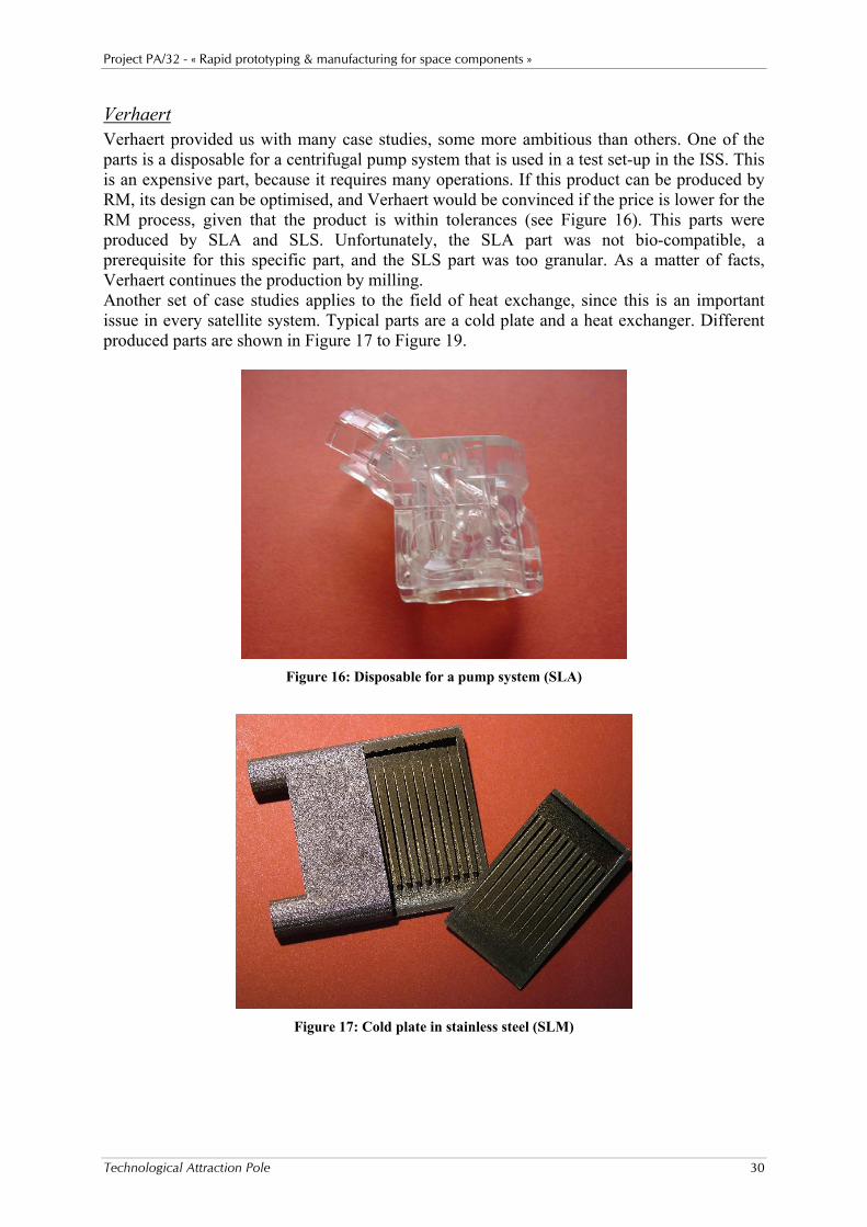
Verhaert Verhaert provided us with many case studies, some more ambitious than others. One of the parts is a disposable for a centrifugal pump system that is used in a test set-up in the ISS. This is an expensive part, because it requires many operations. If this product can be produced by RM, its design can be optimised, and Verhaert would be convinced if the price is lower for the RM process, given that the product is within tolerances (see Figure 16). This parts were produced by SLA and SLS. Unfortunately, the SLA part was not bio-compatible, a prerequisite for this specific part, and the SLS part was too granular. As a matter of facts, Verhaert continues the production by milling. Another set of case studies applies to the field of heat exchange, since this is an important issue in every satellite system. Typical parts are a cold plate and a heat exchanger. Different produced parts are shown in Figure 17 to Figure 19.
Figure 16: Disposable for a pump system (SLA)
Figure 17: Cold plate in stainless steel (SLM)

Project PA/32 - « Rapid prototyping & manufacturing for space components »
Technological Attraction Pole 31
Figure 18: Heat exchanger in Stainless Steel (SLM)
Figure 19: Spiral heat exchanger in Stainless Steel (SLM)
OIP OIP proposed to produce a frame that is used to mount Optical components. The tested solution was to build a near net shape part by aluminium investment casting and a post machining to reach the tolerances. This frame presented very thin parts, which caused already problems of warping of the wax model and the casting of the part. The tolerances were too tight for the foundry so a post machining was required. The aluminium casting part was not rigid enough to withstand the machining efforts; it vibrated at the time of the milling tests. On this part, some areas are nearly unreachable even in 5-axis milling. The part should be redesigned with stiffeners to reinforce first the wax model and then the aluminium part during milling. These stiffeners should be milled at the end of the machining. This results in a partial loss of the advantage of the rapid prototyping technique comparing traditional milling.

Project PA/32 - « Rapid prototyping & manufacturing for space components »
Technological Attraction Pole 32
Figure 20: Frame
Amos Amos is interested in the possibilities of making larger SiC parts for elements of optical systems. There is not yet a solution for so large parts. However, some smaller parts are built. See task 9.
Lambda X In the space project ICAPS-SRE a non-metallic and no magnetic conductive material was needed for a lens holding structure. Another objective was to validate a new concept for the clamping of the lenses, a “bayonet” locking ring instead of the normally used threaded retaining ring. A solution could be found in some ceramic-like material (with no magnetic conductivity) specifically in this case ToolingB. This silica filled epoxy resin is an electrical insulator and has a high stiffness. It is the stiffest composite material currently available in RM with a Young’s modulus of 10750 Mpa. This seven-part lens-holding structure was produced in ToolingB by Optoform. The set-up successfully withstood a random vibration spectrum of 6.5 grms between 20 and 2000 Hz for 30' in the X and 60' in the Y-direction. However, some remarks must be made on the use of this RP technology. The accuracy is obviously too low to guarantee a good alignment of the optics. This requires to over-dimension and post-machine the critical parts afterwards. For this application, an appropriate coating which can harden and blacken the surface at the same time is necessary to avoid dust particles contamination of the optics and to avoid internal reflections. By choosing ToolingB, the demand for a non-magnetic material, not interfering with existing magnetic fields, was fulfilled. However, other problems have to be solved in order to make it compatible with the optical constraints and with the ‘space’ constraints.

Project PA/32 - « Rapid prototyping & manufacturing for space components »
Technological Attraction Pole 33
Figure 21: Lens support
Techspace Aero & Sabca The case studies suggested by Techspace Aero and Sabca are rather similar. The aim is to demonstrate the possibilities to build aluminium parts with complex internal geometries or three-dimensional internal cooling channels. The models proposed by TechspaceAero and Sabca are respectively a lubrication group and a hydraulic actuator. Although aluminium is not yet available on the 3DP machines, it is interesting to use bronze infiltrated stainless functional parts instead to evaluate the current limits of this technology for these applications. Test parts are produced to characterise the process (see Figure 22). The post treatments trials show that an excessive infiltration could fill the small holes. The technique of infiltration is currently being improved and additional equipment is purchased to improve the infiltration process. Test parts built on the R10 machine are in the pipeline for infiltration.
Figure 22: Test part with different sizes of cooling channels (1 to 8 mm)
Because the previous parts were too big to produce at this moment, Sabca has proposed a smaller, massive part with internal channels that was built on the Prometal R10. The debinding and bronze infiltration post-process was done under argon flow, which explains the dark colour of the part (see Figure 23). A thermal cycle under hydrogen would have eliminated a large amount of carbon and making the part more clear and brilliant.

Project PA/32 - « Rapid prototyping & manufacturing for space components »
Technological Attraction Pole 34
Figure 23: Parts with complex internal geometry
The part was produced with its original design i.e. with intersecting straight channels. It would be possible to optimise its design: the technique allows curved channels and a greater freedom of design.
Sonaca For Sonaca, the objective was to produce low cost RTM (Resin Transfer Mould) moulds used to cast a high temperature resin to produce parts for space components. Two solutions were considered: the Optoform process with the ToolingB material and the Prometal process with stainless steel infiltrated by an epoxy resin. The goal of this study was to validate the behaviour of the RTM mould regarding the mechanical and thermal constraints of the injection of a small series of composite parts (glass fibber + RTM120 resin). The next step was to compare the RM solution to classical milling in terms of lead-time, cost and efficiency. The mould had to allow the vacuum (airtightness), next to bear the injection pressure of 2 to 4 bars, and finally to withstand the 120°C curing during 6 hours in the oven. This mould, designed in four parts to facilitate the part release, was built in ToolingB by Optoform. The technical success of the project is complete. The mould, quickly operational, made it possible to produce composite parts without major problems. The mould is 60% cheaper than an aluminium mould produced by machining. Moreover, the lead-time was much shorter. These points are particularly interesting in this case, in which only 6 composite parts were needed. The second solution, infiltrated stainless steel420 by Prometal, was started but did not lead to a successful solution, due to the problems related to the installation of this machine at the moment. Several attempts ended up in broken down parts, not useable.

Project PA/32 - « Rapid prototyping & manufacturing for space components »
Technological Attraction Pole 35
Figure 24: RTM mould
A second technical-economical study consisted in building two representative parts for the satellite Pleiade structure by rapid manufacturing and comparing to the milling solution, the two parts, being STRO (polyamide) and the CMGM (toolingB) Sonaca wanted to complete the mechanical characteristics available on RM materials to allow their engineering and design department to dimension parts. We provided them many test-samples: traditional tensile and compression test bars and more specialised bearing (for riveted assemblies), thread tearing and torque limit tests samples (for screwed assemblies) were realised in ToolingB by Optoform, in PA by laser sintering and in aluminium by MCP casting. Time was too short for Sonaca to redesign these parts so the original aluminium design was used to produce the STRO in PA by laser sintering and the CMGM in ToolingB by Optoform. The prices and lead-time comparison is given in the following chart.
Alu.7050(milling) PA (sintering) 1005 g 341 g
STRO 1part
€ 3565 - 15 days € 1560 - 5 days Alu.7050(milling) ToolingB (Optoform) 1358g 776g
CMGM 1part
€ 5341 - 15 days € 1444 - 5 days
Figure 25: STRO (PA) and CMGM (ToolingB)

Project PA/32 - « Rapid prototyping & manufacturing for space components »
Technological Attraction Pole 36
K.U.Leuven For the study of lightweight structures, rocket models are made with different RP/RM technologies to demonstrate the possibilities for parts with a very complex shape or with an internal structure:
- laser sintering (PA sintering), - stereolithography (Viper and standard machines) - Prometal.
Figure 10 (task 6) shows the complexity of the definition of the rockets. The idea is to compare two kinds of technologies concerning the speed of producing the same complex structure. The major difference is the data processing:
- High-resolution stereolithography (Viper) and selective laser sintering: these processes are based on vector drawing for the polymerisation or the sintering of the material. It takes about 24 hours to produce 4 parts simultaneously (height 70 mm) with the Viper (high definition stereolithography) and about 19 hours to produce a single part of 187 mm high with the standard stereolithography machine. The numerous short vectors to be drawn during the process explain this very low building speed.
- Prometal: this technology is based on a bitmap of points since the Prometal process is working like a 2D printer. So the production of the racket should take less time (the tests must be done). Only the pre-processing will be time consuming but it may be done at night, avoiding the slowdown of the building process, which is the most expensive.
Task 11: Dissemination of results and guidelines
As an output of the project, a guidelines document is prepared. It includes a description of the state of the art of the RP/RM techniques and the properties of the currently available materials. A description is given of the design requirements in order to have a piece taking maximum advantage of the techniques. The numerous case studies developed in the frame of this project are described in a systematic way to show the best way to proceed for designing such pieces. Finally a view is given to the future of RP/RM and the next steps in developing the technique to make it compatible with space instrumentation. Here is the structure of the document: • Introduction • Working principle of RP/RM techniques • Specificity of RP/RM techniques (in terms of accuracy, price, …) • Materials • Designing for RP/RM • Examples of case studies • Future of RP/RM • Appendices

Project PA/32 - « Rapid prototyping & manufacturing for space components »
Technological Attraction Pole 37
Summary
This report presents the activities performed during the TAP-PAT project n° 32 on “Rapid Prototyping and Manufacturing for space components”. A network of organisations (K.U.Leuven, CRIF, CSL) and industrial partners (AMOS, OIP, Verhaert, Materialise, Sonaca, Techspace Aero, Sabca and Lambda X) has been established. During regular meetings, all members have shared their needs, requirements and solutions in the domain of RP, RPD and RM for spatial applications. It can be concluded that the partnership in the project was fruitful. Many opportunities could be taken because of the good co-operation. The Belgian nature of the co-operation proved to be optimal. The technical objective of the project - to borrow generic technologies from the domain of ‘rapid prototyping’ (RP), ‘rapid product development’ (RPD) and ‘rapid manufacturing’ (RM) and to apply, adapt and further develop those technologies to make them applicable to the development and fabrication of prototypes and components for the spatial sector – is fulfilled for the majority of proposed tasks. The most important contributions can be summarised as follows: Task 1: Needs, requirements, initial specs. During the meetings and contacts, this information is gathered. This has resulted in
a re-orientation of the project. The results will be included in the guidelines. Task 2: rbit conditions Testing CSL has performed outgassing tests, cryogenic resistance tests and vibration tests. Task 3: Stereolithography A curtain recoating system has been developed and is optimised, implemented,
and a patent has been filed. The entrapment of air bubbles is investigated. Task 4: Optoform The development of parts in stainless steel has continued. Avoiding residual
carbon is investigated. Task 5: SLS techniques A lot of fundamental research is performed. A process monitoring system is
installed. The processing of Ti-6Al-4V has proved to be successful. Strategies and methods are implemented to be able to meet the high demands of space industry.
Task 6: Porous and hollow light-weight components or parts with gradient properties Various types of hollow parts are produced and tested. Task 7: Jet-based RP technologies The process is optimised further. Several furnace cycles have been studied. Task 8: Deposition of masks or pattern on a substrate There was not enough interest to perform this task. Task 9: RP/RM technologies to produce optical components Some parts in SiC are produced by Optoform. Task 10: Case studies Many case studies demonstrate the possibilities of all technologies. Task 11: Dissemination of results and guidelines A report will be written and presented to the users’ committee in May 2006.

Project PA/32 - « Rapid prototyping & manufacturing for space components »
Technological Attraction Pole 38
The major effort has gone to tasks 1, 4, 5, 6, 7, 10 and 11. Task 8 was not performed, because of technical difficulties in combination with less interest from industrial partners. Its efforts were carried over to the other tasks. Especially task 10 has got a lot of attention, according to the demands of the users’ committee. A fibre laser and the process monitoring system were bought on budget of TAP. The old SLM machine was updated. New furnaces were installed. With this new equipment, we can be sure that the project can compete around the world. The group now possesses a wide range of equipment.
• Concept Laser M3Linear, SLM and laser erosion of metals (K.U.Leuven) • DTM Sinterstation 2000 with 200W CO2 Laser, SLS of polymers and polymer coated
metals (K.U.Leuven) • Own build SLM machine with 300W fibre laser, equipped with a monitoring system,
SLM of metals and ceramics (K.U.Leuven) • Own build SLA machine, with a curtain recoating system • Oven for the infiltration process (K.U.Leuven) • Prometal, RX1 (small machine) and R10 (large one) (CRIF) • Debinding furnace max. 1200°C / hydrogen (CRIF) • Sintering furnace max. 1600°C / hydrogen or vacuum (CRIF) • SLA Viper normal and high resolution (CRIF) • EoSint P350 (CRIF) • EoSint M250XT (CRIF) • Optoform (one for material development and one for validated materials) (CRIF) • Thermojet for wax models (CRIF) • MCP HEK metal vacuum casting system (CRIF)
Manufacturing by RP&M is not only a matter of choosing the right technology and material, it is also a matter of adapting the geometry of the parts to fully take advantage of the processes’ capabilities. Many case studies clearly give an idea of the possibilities and the limitations of different processes. A lot of data was obtained. The needs and requirements, the design rules, the capabilities, etc. will all be brought together in a large report and will be presented in May 2006.

Project PA/32 - « Rapid prototyping & manufacturing for space components »
Technological Attraction Pole 39
References
• Wohlers Report 2005, An in-depth worldwide progress report on the Rapid
Prototyping, tooling, and manufacturing state of the industry, Annual Worldwide Progress Report, Wohlers Associates Inc, ISBN 0-9754429-1-0.
• Kruth J.-P., Mercelis P., Van Vaerenbergh J., Froyen L., and Rombouts M., Advances in Selective Laser Sintering. International Conference on Advanced Research in Virtual and Rapid Prototyping, VR@P, 2003.
• Kruth J.-P., Mercelis P.; Froyen L., Rombouts M. Binding Mechanism in Selective Laser Sintering and Selective Laser Melting (invited paper). Proceedings of Solid Freeform Fabrication Symposium 2004, Austin, Texas, August 2-4, 2004, 44-59. (Best presentation award)
• Levy G.N., Schindel R., Kruth J.-P. Rapid Manufacturing and Rapid Tooling with Layer Manufacturing (LM) Technologies, State of the Art and Future Perspectives (keynote paper). Proc. of the international Conference on Competitive Manufacturing, COMA 2004, Stellenbosch, South Africa, February 4-6, 2004, 29-52.
• Kruth J.-P., Froyen L., Van Vaerenbergh J., Mercelis P., Rombouts M. and Lauwers B., Selective laser melting of iron-based powder, Journal of Materials Processing Technology, Vol. 149, Issues 1-3, 10 June 2004, 616-622.

Project PA/32 - « Rapid prototyping & manufacturing for space components »
Technological Attraction Pole 40
Network and users’ committee
Coordination Meetings with project partners Main issues here are presentation of last-minute results, planning of work ahead, collaboration within different tasks, discussion of individual contacts with members of users’ committee.
• 5th February 2003, CSL • 10th October 2003, CRIF • 26th May 2004, K.U.Leuven • 15th July 2004, K.U.Leuven • 17th March 2005, K.U.Leuven • 10th June 2005, K.U.Leuven
Besides those general meetings, punctual meetings were organized between the researchers of the research teams. Some of those meetings were combined with other meetings (TIS-RM, Belasnet, etc.).
Meetings with the users’ committee On a regular basis, meetings with the users’ committee were scheduled to give an overview of the progression within the project. The aim of these meetings was plural:
• to introduce one to another, such that future contacts could easily be made, • to explain the project’s aim and different tasks to the users’ committee, including a
state of the art in the field of rapid prototyping, • to gain some input from the users regarding the space industry’s needs and
requirements. • to demonstrate the ongoing case studies, and • to give information on the ongoing fundamental research.
There were 4 meetings with the users’ committee. • 10th March 2003, Materialise. Acquaintance of partners, scope of the project and visit
to the facilities of Materialise. • 18th November 2003, CSL. Ongoing case studies, evolutions in the technology, related
to the project and visit to the facilities of CSL. • 7th October 2004, K.U.Leuven, linked to ‘Technologiedag: snel van idee naar product
met laser’, in the library of the science library of K.U.Leuven. Ongoing case studies, outgassing tests and light weight structures.
• 20th September 2005, CRIF. Presentations about new equipment and possibilities, SLM of Ti-alloys, measuring residual stresses and case studies.
One meeting is scheduled for 24th May 2006, with the dissemination of the ‘Guidelines’. For the case studies, there are regular contacts at the involved company to discuss problems concerning a specific case.
Other contacts CSL also has the necessary contacts with ESA to do outgassing tests.
Seminar We helped to organize the ‘Technologiedag: snel van idee naar product met laser’ on 7th October 2004. There were about 50 attendants in total.

Project PA/32 - « Rapid prototyping & manufacturing for space components »
Technological Attraction Pole 41
Publication and valorisation
Papers • Clarinval A., Dormal T. 5 conférences sur les évolutions du prototypage rapide, la
fabrication directe, les matériaux et les applications médicales. Proceedings of MICAD 2004, 31/03/04, Paris.
• Clarinval A. Development of metallic and ceramic material for Optoform process, Polymers and Moulds Innovations, Gent, 2005.
• Dormal T., Gravet D., A new and fast solution for complex metal parts and inserts, Proceedings of Les 10ièmes Assisses européennes du prototypage rapide, Paris, September 14-15, 2004.
• Dormal T., Gravet D., A new and fast solution for complex metal parts and inserts, Proceedings of RPD 2004, Marinha Grande, Portugal, October 12, 2004.
• Dormal T., Gravet D., Rapid toolingcase studies, success and limitations, Proceedings of Euromold 2004 (Modern mould making techniques), Frankfurt, December 1, 2004.
• Dormal T., 3DPrinting metal: A new & fast solution for injection tools, Polymers and Moulds Innovations, Gent, 2005.
• Dormal T., Rapid Manufacturing, FABI, June 2005. • Dormal T., La fabrication directe fait son chemin, Industrie et technologies, 2006. • Gilio M., Al-Bender F. and Kruth J.-P., The dynamics of a moving sheet of liquid, Part
I: Derivation of the 2D equations of motion, European Journal of Mechanics - B/Fluids, Vol. 24, Issue 5, Sept.-Oct. 2005, 555-571.
• Gilio M., Al-Bender F. and Kruth J.-P., The dynamics of a moving sheet of liquid, Part II: Experiments, European Journal of Mechanics - B/Fluids, Vol. 24, Issue 5, Sept.-Oct. 2005, 572-585.
• Kruth J.-P., Froyen L., Rombouts M., Van Vaerenbergh J. and Mercelis P., New ferro powder for Selective Laser Sintering of dense parts, CIRP Annals – Manufacturing Technology 52, 1, 2003, 139-142.
• Kruth J.-P., Froyen L., Van Vaerenbergh J., Mercelis P., Rombouts M., Lauwers B., Selective laser melting of iron-based powder. Journal of Materials Processing Technology, Vol. 149, Issues 1-3, 2004, 616-622.
• Kruth J.-P., Mercelis P.; Froyen L., Rombouts M. Binding Mechanism in Selective Laser Sintering and Selective Laser Melting (invited paper). Proceedings of Solid Freeform Fabrication Symposium 2004, Austin, Texas, August 2-4, 2004, 44-59. (Best presentation award)
• Kruth J.-P., Van Elsen M., Manufacturing of light-weight polymer structures using SLS, Polymers and Moulds Innovations, Gent, 2005.
• Kruth J.-P., Kumar S., Van Vaerenbergh J., Study of laser-sinterability of ferro-based powders. Invited paper, Rapid Prototyping Journal, Emerald Group Publishing Limited, 2005, Vol. 11, Issue no. 5, pp. 287-292.
• Kruth J.-P., Kumar S., Statistical Analysis of Experimental Parameters in Selective Laser Sintering. Advanced Engineering Materials 7 (8), august 2005, 750-755.
• Kruth J.-P. and Vandenbroucke B., Digital manufacturing of biocompatible metal frameworks for complex dental prostheses by means of SLS/SLM, Proceedings of VRAP2005, 2005, 139-145.

Project PA/32 - « Rapid prototyping & manufacturing for space components »
Technological Attraction Pole 42
• Kruth J.-P., Vandenbroucke B., Van Vaerenbergh J. and Mercelis P., Benchmarking of different SLS/SLM processes as Rapid Manufacturing techniques, Proc. Int. Conf. Polymers & Moulds Innovations, 2005
• Levy G.N., Schindel R., Kruth J.-P. Rapid Manufacturing and Rapid Tooling with Layer Manufacturing (LM) Technologies, State of the Art and Future Perspectives (keynote paper). Proc. of the international Conference on Competitive Manufacturing, COMA 2004, Stellenbosch, South Africa, February 4-6, 2004, 29-52.
• Mercelis P., Kruth J.-P., Residual stresses in Selective Laser Sintering and Selective Laser Melting, 2006, accepted for publication in the Rapid Prototyping Journal.
• Rombouts M., Froyen L., Van Vaerenbergh J. and Mercelis P., Production and properties of dense iron based parts produced by laser melting with plasma formation, Proceedings of World Powder Metallurgy Conference PM2004 5, 2004, 115-121.
• Rombouts M., Froyen L., Bourell D. and Kruth J.-P., Surface roughness after laser melting of iron based powders, Proceedings of Second International Conference on Advanced Research in Virtual and Rapid Prototyping VRAP2005, 329-335, 2005.
• Rombouts M., Kruth J.-P., Froyen L. and Mercelis P., Selective Laser Melting of iron and steel powders, Annals of the CIRP, 2006, accepted for publication.
Papers submitted • Van Elsen M., Baelmans M., Mercelis P. and Kruth J.-P. Solutions for modelling
moving heat sources in a semi-infinite medium and applications to laser material processing. International Journal on Heat and Mass Transfer.
• Van Elsen M., Al-Bender F. and Kruth J.-P. Application of dimensional analysis to Selective Laser Melting. Rapid Prototyping Journal.
• Rochus P., Plesseria J.-Y., Kruth J.-P., Van Elsen M., Dormal T., Carrus R., New application of rapid prototyping and rapid manufacturing (RP/RM) technologies for space instrumentation, 57th International Astronautical Congress 2006. Abstract submitted.
PhD. Thesis • Gilio M.; Kruth, J.-P., Curtain Recoating System for SLA, November 2004.
Master Thesis’s • Hoppenbrouwers T. and Van Praet S., Production of light weight nylon components
for aerospace applications through SLS. Promoter: Kruth J.-P.; Coach: Van Elsen M., 2004.
• Aitor D. M., Investigation of air bubbles entrapment in stereolithography parts with curtain recoating. Coach: Gilio M., 2004.
• De Smet K. and Kempeneers B., Design and fabrication of bone scaffolds for tissue engineering using Selective Laser Sintering. Promoter: Kruth J.-P.; Coach: Vandenbroucke B., 2005.
• Meerts K and Vandorpe D., Residual stresses in Selective Laser Sintering and Selective Laser Melting. Kruth J.-P.; Coach: Mercelis P., 2005.
Conferences • International Conference on Lasers In Manufacturing (June 2003), Munchen,
Germany (K.U.Leuven) • LASER 2003 (World Trade Fair for Lasers and Photonics, June 2003), Munchen,
Germany (K.U.Leuven)
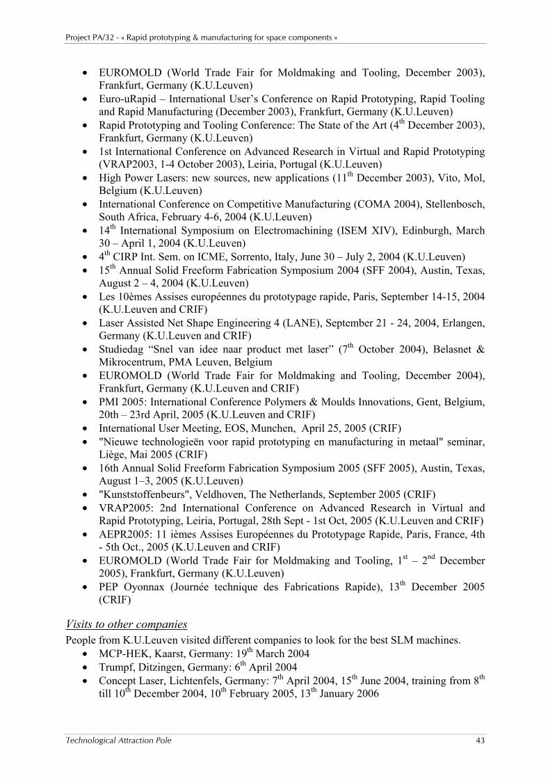
Project PA/32 - « Rapid prototyping & manufacturing for space components »
Technological Attraction Pole 43
• EUROMOLD (World Trade Fair for Moldmaking and Tooling, December 2003), Frankfurt, Germany (K.U.Leuven)
• Euro-uRapid – International User’s Conference on Rapid Prototyping, Rapid Tooling and Rapid Manufacturing (December 2003), Frankfurt, Germany (K.U.Leuven)
• Rapid Prototyping and Tooling Conference: The State of the Art (4th December 2003), Frankfurt, Germany (K.U.Leuven)
• 1st International Conference on Advanced Research in Virtual and Rapid Prototyping (VRAP2003, 1-4 October 2003), Leiria, Portugal (K.U.Leuven)
• High Power Lasers: new sources, new applications (11th December 2003), Vito, Mol, Belgium (K.U.Leuven)
• International Conference on Competitive Manufacturing (COMA 2004), Stellenbosch, South Africa, February 4-6, 2004 (K.U.Leuven)
• 14th International Symposium on Electromachining (ISEM XIV), Edinburgh, March 30 – April 1, 2004 (K.U.Leuven)
• 4th CIRP Int. Sem. on ICME, Sorrento, Italy, June 30 – July 2, 2004 (K.U.Leuven) • 15th Annual Solid Freeform Fabrication Symposium 2004 (SFF 2004), Austin, Texas,
August 2 – 4, 2004 (K.U.Leuven) • Les 10èmes Assises européennes du prototypage rapide, Paris, September 14-15, 2004
(K.U.Leuven and CRIF) • Laser Assisted Net Shape Engineering 4 (LANE), September 21 - 24, 2004, Erlangen,
Germany (K.U.Leuven and CRIF) • Studiedag “Snel van idee naar product met laser” (7th October 2004), Belasnet &
Mikrocentrum, PMA Leuven, Belgium • EUROMOLD (World Trade Fair for Moldmaking and Tooling, December 2004),
Frankfurt, Germany (K.U.Leuven and CRIF) • PMI 2005: International Conference Polymers & Moulds Innovations, Gent, Belgium,
20th – 23rd April, 2005 (K.U.Leuven and CRIF) • International User Meeting, EOS, Munchen, April 25, 2005 (CRIF) • "Nieuwe technologieën voor rapid prototyping en manufacturing in metaal" seminar,
Liège, Mai 2005 (CRIF) • 16th Annual Solid Freeform Fabrication Symposium 2005 (SFF 2005), Austin, Texas,
August 1–3, 2005 (K.U.Leuven) • "Kunststoffenbeurs", Veldhoven, The Netherlands, September 2005 (CRIF) • VRAP2005: 2nd International Conference on Advanced Research in Virtual and
Rapid Prototyping, Leiria, Portugal, 28th Sept - 1st Oct, 2005 (K.U.Leuven and CRIF) • AEPR2005: 11 ièmes Assises Européennes du Prototypage Rapide, Paris, France, 4th
- 5th Oct., 2005 (K.U.Leuven and CRIF) • EUROMOLD (World Trade Fair for Moldmaking and Tooling, 1st – 2nd December
2005), Frankfurt, Germany (K.U.Leuven) • PEP Oyonnax (Journée technique des Fabrications Rapide), 13th December 2005
(CRIF)
Visits to other companies People from K.U.Leuven visited different companies to look for the best SLM machines.
• MCP-HEK, Kaarst, Germany: 19th March 2004 • Trumpf, Ditzingen, Germany: 6th April 2004 • Concept Laser, Lichtenfels, Germany: 7th April 2004, 15th June 2004, training from 8th
till 10th December 2004, 10th February 2005, 13th January 2006

Project PA/32 - « Rapid prototyping & manufacturing for space components »
Technological Attraction Pole 44
• EOS, Munchen, Germany: 11th May 2004
Patents Inventors: J.P. KRUTH & M. GILIO Method to speed up the response of a bent liquid curtain 2004 Filed