technical summary mechanical and piping installation works...
TRANSCRIPT

Technical Summary
Page 1
Technical Summary
Mechanical and Piping Installation Works
MCP Contract
1 Purpose
The purpose of this Call for Nomination is to establish a contract for all mechanical and
piping pre manufacturing, assembly and installation works outside the Tokamak
machine boundary of the ITER Project based in Saint-Paul Lez Durance, France.
The contract will include but not only engineering construction design, procurement of
consumables items, piping insulation, pre manufacturing of supports and piping and
steel platform procurement.
2 Background
ITER is based on the 'Tokamak' concept of magnetic confinement, in which the plasma
is contained in a doughnut-shaped vacuum vessel. The fuel - a mixture of Deuterium
and Tritium, two isotopes of Hydrogen - is heated to temperatures in excess of 150
million °C, forming a hot plasma. Strong magnetic fields are used to keep the plasma
away from the walls; these are produced by superconducting coils surrounding the
vessel, and by an electrical current driven through the plasma.
ITER is a large research facility made of a combination of large conventional industrial
equipment such as the cooling water system and challenging new high tech components
such as diagnostics, superconductive magnets, etc. To ensure the future operation of all
ITER subsystems a large amount of power and control cables will have to be designed,
identified, routed and installed.
For more information on ITER Project please visit our site www.iter.org.
3 Scope of Work
This contract includes all Mechanical and Piping Installation works outside the
Tokamak vaccum boundary which are in IO scope for Phase I configuration, or which
IO executes on behalf of Domestic Agencies (DA).
The scope of this contract includes various activities such as (refer to Annex for more
details):
• Construction documentation,
• Pre-manufacturing and Installation of pipework spools including relative
supports,
Technical Summary
Page 2
• Installation of pre-manufactured pipework spools including procured items from
other DAs in the scope of IO,
• Installation of conventional equipment like pumps, compressors, heat
exchangers, pressure vessels and valves,
• Installation of special components like cryopumps, cold boxes, gas valves boxes,
pipe lines for cryo fluid, vacuum lines,
• Installation of specific systems requiring special cleanliness, techniques or
accuracy (e.g. fuelling lines, transmission lines, waveguides, vacuum lines),
• Procurement, pre-manufacturing and installation of steel platforms and
structures fixed to the buildings for man access or for supporting components or
pipes when procurement or installation is in the scope of IO,
• Installation of the instrumentation which will constitute the process boundary
(e.g. thermowells, in line instrumentation like flowmeters or others),
• Installation Tests (e.g. NDT, pressure test, leak tests and vacuum tests,
calibration),
• Finishing works (e.g. internal cleaning, touch-up paint, thermal insulation,
cladding, labelling and tagging),
• Start-Up and Pre-commissioning Activities,
• Assistance during commissioning activities performed by the IO or DA Operator
of systems,
• The Contractor shall issue all the necessary documentation required to undertake
and to follow-up installation activities and to record all activities (as built
dossier),
NOTE: For some very specific operation (e.g. superconducting joints, optical
alignments) the IO Mechanical & Piping Contractor (MCP) will have to interface with
the companies awarded for the specific operations. The interfacing will be managed by
IO supported by the Construction Manager as Agent (CMA).
The Contractor shall execute works according to instructions, with pricing based upon
tendered unit rates for each type of work.
The Contractor shall have an ITER approved QA Program or an ISO 9001 accredited
quality system in accordance with all the European standards, Construction and Design
rules and French laws and decrees.
All above mentioned works shall be performed by the Contractor on the ITER site at
Saint Paul-lez-Durance in France. The Contractor shall provide all necessary
documentation, means and tooling or temporary works if required to properly manage
and perform the different stages of work.

Technical Summary
Page 3
3.1 Option: LN2 plant in cryo buildings
As an option the Contractor shall install the LN2 plant in cryoplant buildings.
4 Interfaces with Other Companies
The overall set of contracts to be placed for construction activities are shown in the
following figure. A summary of the main interfacing contracts is included in the
following sections.
4.1 IO Construction Management-as-Agent Contractor
The IO placed the contract for Construction Management-as-Agent (CMA) services.
The CMA Contractor shall be responsible for:
• Project Management,
• Works Preparation,
• Site coordination,
• Material management,
• Work supervision, quality control, record keeping,
• Management of Completion Activities,
The CMA interfaces with the Contractor at different steps of the works (preparation,
quotation and scheduling, performance and acceptation).
The CMA acts as the Engineer for this Works Contract under the FIDIC “Red Book”.
Construction Manager-as-Agent
Domestic
Agency
Works
Contractors
Machine
Assembly
Works
Mechanical &
Piping
Works
Specialized
Works
Super
Conducting
Joints
Cryogenics
Special
Techniques
Lifting & Handling
Tokamak
Works Contracts Support Contracts
Access, Plant Hire
Civils & Finishing
Balance of Plant
Electrical, I&C
Works
Scaffolding
CMA
ASY MCP EIC SPx
LFT
SCF
APH
CIV

Technical Summary
Page 4
4.2 Cable Supply, Electrical and I&C Installation Works
Contractor
The IO is currently tendering for Cable Supply, Electrical and I&C Installation Works
(EIC) Contractor. The EIC Contractor shall be responsible for design, cable harness pre-
manufacturing, cable pulling, termination, bus-bars, switch equipment, electrical
equipment installation and hook-ups.
The scope of this contract includes installation of:
– DC Busbar and Switching Network
– Power, Instrumentation and Control Cables
– Cable Trays and Conduits
– Low Voltage Panels and Junction Boxes
– Instrumentation and Control Cabinets
– Cabling Infrastructure for Control System
– Instrumentation and related Equipment
– Access Control and Security Equipment
4.3 Tokamak Machine Assembly
The IO intends to launch the procurement tendering process the Tokamak Machine
Assembly contract. The Contractor shall be responsible for all mechanical and electrical
assembly and installation works up to the nearest physical interface at or beyond the
outermost vacuum boundary of the Tokamak, including all in-vacuum cabling – with
the exception of specialised works (such as super-conducting magnet joints) and
installation of the cryostat (INDA scope).
4.4 Lifting & Handling, Scaffolding and Access
IO intends to tender a contract for the unloading, inspection, storage, preservation and
delivery on-site of Material to the construction site (on-site logistics).
In addition, the IO will put in place an On-site Lifting and Handling Contract for the
lifting and handling of Material within the ITER Site. These contracts shall be used by
the works contractors. Similarly, IO will put in place a contract for the provision of
scaffolding and related access means for use by all works contractors.

Technical Summary
Page 5
5 Conflict of Interest
There is a strict conflict of interest situation between the CMA contract and Works
contracts. That means that no member or subcontractor of the CMA contract can
participate to any works activities.
Awarded consortium members (or part of any joint liable type of legal grouping
arrangement) shall not participate in the following contracts as consortium member:
− Cable Supply, Electrical and I&C Installation Works Contract,
− Machine Assembly Contract.
However, the companies involved in one works contract as consortium members, are
authorized to participate to the above mentioned contracts as sub-contractors.
This limitation does not apply to contracts already placed by the IO by the time of the
signature of this contract, or to contracts placed or to be placed by the Domestic
Agencies unless specifically mentioned before signature of the said contracts.
The same principles as above apply to Parent Companies or subsidiaries.
By "Parent Companies" it is meant a firm that owns or controls other firms (called
subsidiaries) which are legal entities in their own right. IO will consider as a subsidiary
a company controlled by another (the parent) through the ownership of greater than 50
percent of its voting stock. This basically represents 50% + 1 vote.
Voting Stocks (or voting shares) are the ordinary shares the ownership of which gives
an entity the right to vote in the issuing firm's annual general meeting. The ultimate and
exclusive right conferred by a lawful claim or title, and subject to certain restrictions to
enjoy, occupy, possess, rent, sell, use, give away, or even destroy an item of property.
Parent Companies can be a holding. ln that particular case, and in order to simplify the
implementation of this principle for holdings which definition can vary with the legal
system, the IO will retain the same definition as for Parent Companies (> 50% of voting
shares).

Technical Summary
Page 6
6 Timetable
The tentative timetable is as follows:
Call for Nomination July 2016
Pre-qualification August 2016
Deadline for receipt of pre-qualification: October 2016
Issue of the Call for Tender November 2016
Tenderers’ meeting December 2016
Tender Submission Date February 2017
Award of the Contract May 2017
Contract Signature July 2017
The estimated duration of the contract is 9 years.
7 Experience
The Contractor and its personnel shall have adequate experience in piping and
mechanical installation works. This includes but it is not comprehensive:
• Pipes and supports,
• Vacuum systems installation,
• Installation of sensitive components within a very tight tolerance,
• All kind of in-line components,
• All kind of mechanical equipment for plants,
• All kind of tanks.
The Contractor shall demonstrate to have adequate experience in installation of
equipment in compliance with:
• French Order dated 7 February 2012,
• ASME III or RCC-M or equivalent nuclear code,
• ASME B31.3,
• ESPN regulation,
• French Decree n°99-1046 of December 13 1999 or European Directive
97/23/EC and in the Directive 2006/42/EC relative to pressure equipment.

Technical Summary
Page 7
In addition, it is required to have experience in:
• International projects, i.e. customer(s) and/or supplier(s) from different
countries, with all documentation being delivered in English,
• Construction sites with high occupational safety standards.
For specific domains, the technical experience of the sub-contractors will be considered
at the pre-qualification stage.
8 Candidature
Participation is open to all legal persons participating either individually or in a
grouping (consortium) which is established in an ITER Member State. A legal person
cannot participate individually or as a consortium partner in more than one application
or tender of the same contract. A consortium may be a permanent, legally-established
grouping or a grouping, which has been constituted informally for a specific tender
procedure. All members of a consortium (i.e. the leader and all other members) are
jointly and severally liable to the ITER Organization.
The consortium grouping shall be presented at the Pre-Qualification stage. The
Candidate’s composition cannot be modified without the approval of the ITER
Organization after the Pre-Qualification.
Legal entities belonging to the same legal group are allowed to participate separately if
they are able to demonstrate independent technical and financial capacities. Candidates
(individual or consortium) must comply with the selection criteria. The IO reserves the
right to disregard duplicated reference projects and may exclude such legal entities from
the Pre-Qualification procedure.
9 Nuclear liability
The ITER Organization is the nuclear operator of the ITER nuclear fusion facility (INB
174) under French nuclear law. However, unlike other nuclear operators of nuclear
fission installations in France, nuclear fusion installations are not covered by the Paris
Convention on nuclear third party liability for the time being. Pending negotiations with
the Contracting parties to the Paris Convention, the special nuclear liability regime (i.e.
limited strict liability of the nuclear operator) implemented by the Paris Convention
does not apply.
Therefore, the ITER Council, by a decision of 2009 endorsed that until a solution is
found, the ITER Organization may assume this responsibility by providing a declaration
and waiver of indemnity regarding nuclear liability to indemnify suppliers of the IO and
their subcontractors in case they are held liable, based on the principles of the Paris
convention, this in the understanding that if no regulatory solutions could be found
before nuclear operations of the ITER facility started, a proper mechanism would be

Technical Summary
Page 8
established by the ITER Members in accordance with Article 15 of the ITER
Agreement.
This declaration and waiver of indemnity regarding nuclear liability shall be included in
the contract signed by the Contractor and the IO.
10 CEAR Insurance
The ITER Organization and Fusion for Energy, the European Domestic Agency in
charge of providing buildings to the ITER Organization, have taken out an insurance
policy to cover:
− the risk of physical loss or material damage to the Project arising from whatsoever
cause except if excluded,
− as well as to cover all sums which the Insured shall become legally liable to pay in
respect of or arising from accidental bodily injury to or illness of third parties and
accidental loss or damage or destruction to property belonging to third parties
occurring during the construction/erection period on the construction site and
arising from or in connection with the Insured Project unless excluded (CEAR
Insurance Policy)
Contractors, Subcontractors of any tier and suppliers and/or consultants (in respect of
their site activities) are also covered by this insurance policy and as such are only liable
for the deductible, the exclusions or above the limit of coverage mentioned in the
insurance policy in accordance with the insurance certificate that will be provided to
you during the next phase of the tender process.
This insurance policy carries a global aggregate coverage limit of Euro 1,000,000,000
(one billion Euro).
The ITER Organization and Fusion for Energy will cover their own buildings used by
the contractors to perform their duty on Site, excluding the content being the
contractor's property.
The CEAR insurance policy subscribed by the ITER Organization and Fusion for
Energy shall not affect the contractor's liabilities or obligations.
11 Subcontracting Rules
Sub-contracting is allowed, but it is limited to two levels and its cumulated volume is
limited to 50% of the total contract value. As mentioned in the Article 7, the experience
of sub-contractors will be considered at the pre-qualification stage for specific domains.

Technical Summary
Page 9
Annex
Mechanical and Piping Installation Works Contract
Overview of Scope of Work

Page 1
Mechanical and Piping Installation Works
Contract
Overview of Scope of Work
Page 2
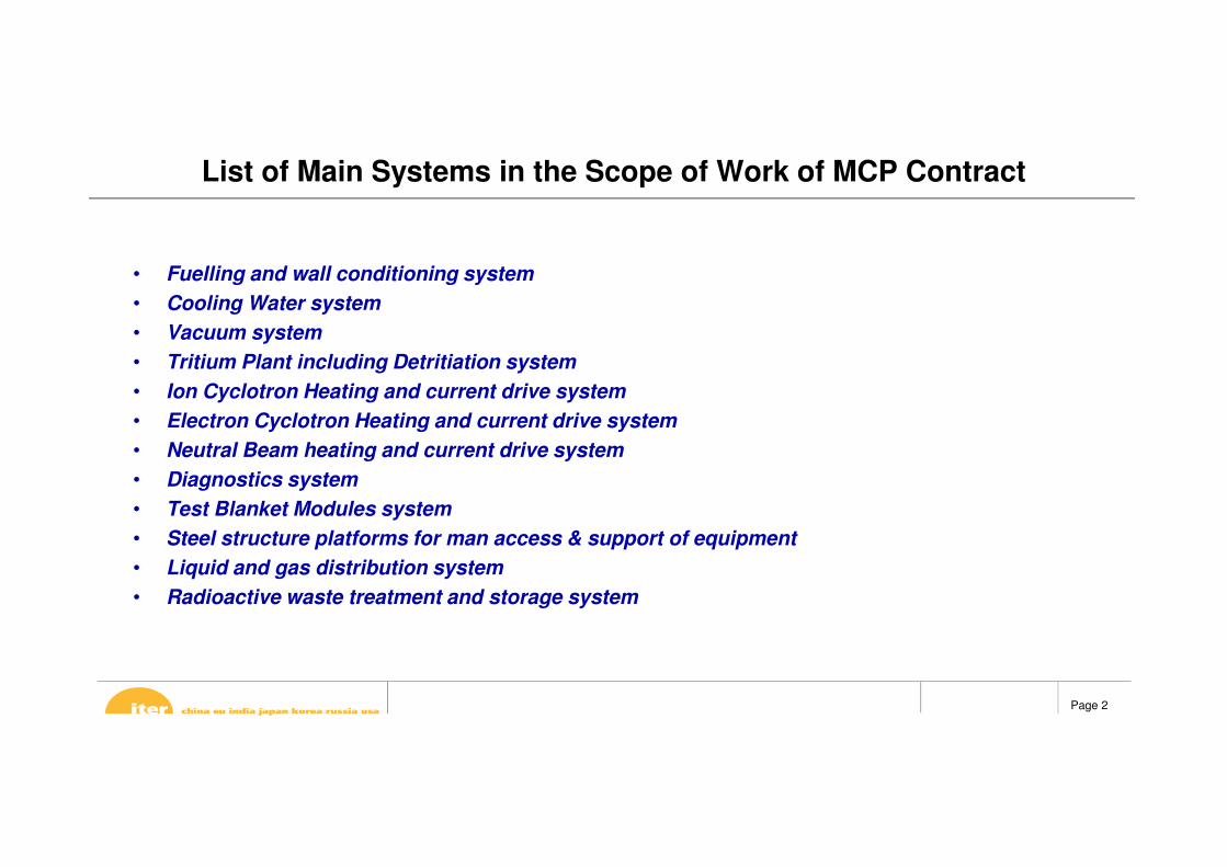
List of Main Systems in the Scope of Work of MCP Contract
• Fuelling and wall conditioning system
• Cooling Water system
• Vacuum system
• Tritium Plant including Detritiation system
• Ion Cyclotron Heating and current drive system
• Electron Cyclotron Heating and current drive system
• Neutral Beam heating and current drive system
• Diagnostics system
• Test Blanket Modules system
• Steel structure platforms for man access & support of equipment
• Liquid and gas distribution system
• Radioactive waste treatment and storage system

Page 3
Fuelling network - Nuclear Building
Estimated 1,300 m of piping (multi pipe concept) and 12 gas boxes to install
Portion of the system is PIC

Page 4
Fueling Network – piping & equipment
Gas Distribution System (GDS) Manifold – Multicore Gas Line
System Material No. of process pipes within Guard pipe
~ No of elements/spools
Tentative Size(mm)
GDSProcess pipes: Austenitic Stainless steel [316 L]Outer jacket: Austenitic Stainless steel [316 L]
6 76
Process pipes: from DN 15
Outer jacket: DN 250
Subsystem Description Qty.(L x W x H)
(m)
Weight (tons)
GIS GVBs Gas Valve Box 10 1.35 x 1.3 x 1.32 2
PIS GVBs Gas Valve Box 2 5

Page 5
Tokamak Cooling Water system (TCWS) – Nuclear Building
Upper pipe
distribution
(blue)
Drying system
(yellow)
Draining (brown – 5 main
tanks are out of scope)
IBED PHTS (blue –
only piping in
the scope)
Lower pipe
distribution
(blue)
Neutral beam PHTS
(pink – Mainly out of
scope)
Vacuum Vessel
PHTS (green)
CVCS
(light blue – Out of
scope)
Approx. pipe length 28,000 m – Stainless SteelNumber of valves 3000Weight of supports 200 tons
TCWS Systems are PICand some component are ESPN classified

Page 6
Subsystem Qty.(L x W x H)
(m)
Weight(tons)
TCWS-VV-PHTS
Primary pump 1 5 x 2 x 2 16.8
Primary Heat Exchanger 1 6.5 x 0.8 x 2 6.3
Pressurizer 1 6 x 6 (dia x h) 9
Baking heater 1 3.1 x 2 x 2.8 3.5
Chemical Additive Skid 1 0.55 x 0.55 1.40
Chemical Injection pump 1 1.2 x 1.2 x 1.7 1.4
Filter booster pump 1 2 x 1x 0.8 1.2
pressure relief tank 1 2.3 x 3.5 x 2.9 6
Decay HX 1 2 x 0.5 x 1.3 0.75
Volume Control Heat Exchanger (Letdown Cooler)
1 3.7 x 0.8 x 1.8 1.9
Decay Heat Pump 1 3650 x 1560 3.2
Volume Control Charging Pumps (Vertical Pumps)
1 0.6 x 0.6 x 1.5 1.5
Charging Pump 1 4 x 1 6.00
Filter 1 0.7 x 0.5 x 2.5 3.28Filter 1 0.7 x 0.5 x 2.5 3.28
Seal Injection filter 10.3 x 1.2(dia x h)
0.80
TCWS Equipment
Subsystem Qty.(L x W x H)
(m)
Weight(tons)
TCWS-DYS
Cyclone separator
1 2 x 1.5 x 4.2 5
Cyclone separator
1 0.9 x 6.5 x 1.5 6.3
Drying Compressor
1 3 x 2.3 x 1.5 4.5
Charging Compressor
1 9 x 3.3 x 3 36.7
Heater 1 4.6 x 0.45 x 1.2 2.6
Demister 1 2.7 x 1.4 x 2.7 4.1
Filter Including local shielding
2 1.2 x 1.2 x 3.3 10.00
CCWS Condenser
1 2 x 1 x 1.5 6.8
CHWS Condenser
1 1 x 0.6 8.40
N2 Storage tank
1 6.4 x 4 x 4 74.00
Economizer 1 2.8 x 1.3 x 2.6 5.5
Buffer Tank #1
1 3.00
Buffer Tank #2
1 1.00
Buffer Tank #3
1 1.00
Buffer Tank #4
1 1.50
Subsystem Qty.(L x W x H)
(m)
Weight(tons)
TCWS-DRS
Waste collector tank
13 x 3 x 8.2(dia x h)
14.7
Refilling Pump (vertical)
10.7 x 4
(dia x h)0.58
Sump Tank Pump (vertialpump)
10.6 x 3.61(dia x h)
0.33
Safety Drain Tank Transfer Pump (Vertical Pump)
10.0.6 x 4 (dia x h)
0.58
NBI PHTS drain and refilling transfer pump (vertical pump)
10.0.6 x 4 (dia x h)
0.58

Page 7
Component Cooling Water System (CCWS)Chilled Water System (CHWS)Heat Rejection System (HRS)
• Location: throughout the site;
• Scope of work is limited to the
installation inside of the
Buildings.
CCWS – CHWS – HRS – Partially Nuclear Building
Function: transfer heat from Tokamak and auxiliary systems to Heat Rejection System (HRS).
Total length about: 19,000 m Stainless Steel (650 tons of pipe work) in scope6,000 m Carbon Steel (100 tons of pipe work) in scope

Page 8
Subsystem Description Qty.(L x W x H)
(m)
Weight(tons)
CCWS-2A
Plate Heat Exchangers
Stainless Steel Plate Heat Exchanger
1 7.0 x 2.0 x 4.5 30
Pressurisation Units
Vertical Nitrogen gas Pressuriserwith access ladder & platform
1 1.1 ø x 4 2.5
CCWS-2A Pumps
Centrifugal Pumps 3 3.0 x 1.5 x 1.5 6.3
Polishing Unit 1+1
Subsystem Description Qty.(L x W x H)
(m)
Weight(tons)
CCWS-2B
Plate Heat Exchangers
Stainless Steel Plate Heat Exchanger
2 4.0 x 1.5 x 3.2 10
Pressurisation Units
Vertical Nitrogen gas Pressuriserwith access ladder & platform
1 1.2 ø x 4.0 2.5
CCWS-2B Pumps
Centrifugal Pumps 3 4.0 x 2.0 x 1.5 7
Polishing Unit 1+1
Cooling Water Equipment
Subsystem Description Qty.(L x W x H)
(m)
Weight(tons)
CCWS-2D
Plate Heat Exchangers
Stainless Steel Plate Heat Exchanger
3 6 x 2 x 4.5 40
Pressurisation Units
Vertical Nitrogen gas Pressuriserwith access ladder & platform
1 1.5 ø x 2.0 5
CCWS-2D Pumps Centrifugal Pumps 4 5.0 x 2.5 x 3.0 15
Caustic addition system
1 2.3 x 2.1 x 1.9 2
Subsystem Description Qty.(L x W x H)
(m)
Weight(tons)
CCWS-2C
Plate Heat Exchangers
Stainless Steel Plate Heat Exchanger
1 4.0 x 2.0 x 2.5 10
Pressurisation Units
Vertical Nitrogen gas Pressuriserwith access ladder & platform
1 1.5 ø x 4.0 10
CCWS-2C Pumps Centrifugal Pumps 2 3.0 x 1.0 x 1.5 10
Polishing Unit 1+1

Page 9
Subsystem Description Qty.(L x W x H)
(m)
Weight(tons)
CHWS-H1-Train B
Water cooled chillers Water Cooled Centrifugal Chiller 4 4.5 x 1.5 5.0
Chilled water pumps Inline Centrifugal Pumps 4 2.5 x 1.25 2.0
Condenser water pumps
Inline Centrifugal Pumps 4 2.5 x 1.25 2.5
Dry coolers Air Cooled Dry Cooler 4 16.0 x 3.0 2.5
Pressurisation Unit Vertical Nitrogen gas Pressuriser with access ladder & platform 2 1.5 x 1.5 0.8
Cooling Water Equipment
Subsystem Description Qty.(L x W x H)
(m)
Weight(tons)
CHWS-H1-Train A
Water cooled chillers
Water Cooled Centrifugal Chiller
4 4.5 x 1.5 5.0
Chilled water pumps
Inline Centrifugal Pumps
4 2.5 x 1.25 2.0
Condenser water pumps
Inline Centrifugal Pumps
4 2.5 x 1.25 2.5
Dry coolersAir Cooled Dry Cooler
4 16.0 x 3.0 2.5
Pressurisation Unit
Vertical Nitrogen gas Pressuriserwith access ladder & platform
2 1.5 x 1.5 0.8
Subsystem Description Qty.(L x W x H)
(m)
Weight(tons)
CCWS-1
Plate Heat Exchangers
Stainless Steel Plate Heat Exchanger
14 6.0 x 2.0 x 4.5 40
Pressurisation Units
Vertical Nitrogen gas Pressuriserswith access ladders & platforms
2 2.8 ø x 5.0 35
CCWS-1 PumpsCentrifugal Pumps
6 5.0 x 2.5 x 3.0 15

Page 10
Cooling Water Towers, Pumps and Heat Exchangers buildings 67/68/69
125 m115 m
1,800 m of pipes above DN1000,
2,200 m of pipes DN25-DN750,
ASTM A 672 Gr B60 CL-12 FROM ASTM A 515
GR 60 PLATES and ASTM A 53 Gr. B, Type E
10 Cooling Water Tower Cells 64m x 32m x
22m,
13 vertical circulation pumps 3.0m ø x 12.0m,
17 heat exchangers,
10 circulation pumps,
3 pressurizer tanks,
3 Chemical dosing System 4m x 2m x 2m,
2 ozonation plant equipment 12m x 3m x 3m
10 set stoplog gate & screen 3.2m x 0.5m x 4m

Page 11
Vacuum system – Nuclear Buildings
About 10,000 m of stainless steel piping from DN25 to DN300Vacuum components: cryopumps, cold valve boxes, gas analyzer
Portion of the system is PIC

Page 12
Tritium – Nuclear Building
Hot Cell Building
(out of current
scope)
Tokamak Building
About 100 m of stainless steel
piping is remaining in the scope
of this contract
System is PIC
Tritium Building (out of current
scope)

Page 13
Ion Cyclotron Heating and CD system – Nuclear Building
Transmission lines length about 200m, DN 300, (45 kg/m)
System is PIC

Page 14
Ion Cyclotron Heating and CD system – RF Heating Building
Supporting structure installation, transmission line connections (around 400m), cooling
pipes installation (around 200m)
Cooling pipes
Supporting structure Transmission
line connections

Page 15
Electron Cyclotron Heating and CD system – Nuclear building
Materials for the waveguides only:Circular waveguide – 2.1 m section 1,400 mWaveguide coupling 800 itemsPumping Tees 8 itemsBends 60 items
Transmission lines from
RF Heating Building to
Tokamak Building
RF Heating Building
Tokamak Building
NOTE: Requires precise alignment ±0.5mm over 4m distance between supportsRequires good practice with ultra high vacuum and high power microwaves
System is PIC

Page 16
Primary steps for waveguides installation:
• Metrology and installation of fiducials
• Installation of secondary steel structure
• Installation of waveguide support frames (˜150)
• Pre-alignment of supports
• Installation of waveguides
• Installation of cooling lines (˜2,000 connections)
• Alignment and vacuum tests
Electron Cyclotron Heating and CD system – Nuclear Building
Installation of Gyrotron Ancillaries in RF Building:
• Gyrotron Support structures (8 Al frames 1.5m by 1.5m base ˜2m height)
• 8 Cooling manifold and feeds

Page 17
Neutral Beam – Nuclear building
Captive pipes only, length 117 m
Transmission lines from
Heating Building 15 to
Tokamak Building 11
NBI PHTS for HNB1 NBI PHTS for HNB2NBI PHTS for DNB
CCWS pipes

Page 18
SF6 system for HNB 2SF6 distribution system at HV Deck room
SF6 system for HNB 1
Neutral Beam – Nuclear building

Page 19
CTS launcher
CTS receiver
Pipework :
Bridges, connection
points, estimated length
<50 meters
Cooling lines for laser
systems, estimated
length <500 meters
Diagnostic systems – Nuclear Building
Tokamak complex
building - L1 level

Page 20
wave guide
Cable
wave guide & optical
fiber
Diagnostic systems – Nuclear Building
Tokamak complex
building - B1 level
Page 21
Test Blanket Module System – Tokamak Complex Building
System Material Schedule Size(mm)
TBS Connection Pipes for coolant systems
ASTM A312M GR.TP316L or
RCC-MR Section 2, RM-3342 GR. 1.440480S to 160S DN80 to DN100
TBS Connection Pipes for TES,TRS, TAS, NAS systems
ASTM A312M GR.TP316L or
RCC-MR Section 2, RM-3342 GR. 1.44045S to 40S DN15 to DN50
TBS Connection Pipes for CCWS-1 ASTM A312M GR.TP316L 160S DN100 to DN250
Steel metallic supports Stainless Steel 304
Only TBS Connection Pipes system is in the scope (red marked for coolant systems):• ≈ 4 km of pipes + piping mechanical supports +
steel supports + thermal insulation
• two water decay tanks
All equipment are PIC and are either pressure equipment (ESP) or nuclear pressure equipment (ESPN)

Page 22
Radioactive waste treatment and storage system piping
Overview of waste treatment pipes at B2 in Tokamak Building Complex
Length around 200m

Page 23
Type A Rad waste System (RWST) - Seamless pipe(Piping Outside Bio-shield &Cryostat)
System Material Schedule Size(mm)
Type A - RWST ASTM A312M GR.TP304L 40S DN50
Radioactive waste treatment and storage system piping

Page 24
Steel structure for platforms, walkways and piping supports
Material Material Quantity (kg)
Steel structure for piping supports
Carbon steel and stainless steelTo be
estimatedSteel structure for
platformsStructural Carbon steel 5000 m2
Various scope of installation works
Building Services
System Length Material Size(mm)
Liquid and Gas pipesHVAC ducts
DrainageFire protection
1000 mCarbon steel and stainless
steelDN20 to DN150

Page 25
Overview of the procurement strategy related to the installation works
MaterialVolume (% of total
length of pipe)
Pipe raw material 10%
Spool prefabrication 60%
Steel structure for piping supports 60%
Support prefabrication 60%
Steel structure for platforms 100%
Thermal insulation 90%
Paint / coat 90%
Anchors 50%
Procurement strategy

Page 26
OPTION - Cryoplant – Cryo Buildings
Liquid helium
(LHe) Plants
cold boxes
and
Compression
station
Liquid nitrogen (LN2) plant
and auxiliary system
Cold boxes Compressors Tanks
Cryolines &
Cryoplant
Termination Cold
Box (CTCB) 1 2 3
1
2
3
2
3
3
22
1
1
3
2
2
2
1
1
1
Cryo building
Tokamak building
HQ bldg
Only LN2 plant (blue) is part of the scope as an option