technical specification qualification engineering for...
TRANSCRIPT
PDF generated on 03 Mar 2015DISCLAIMER : UNCONTROLLED WHEN PRINTED – PLEASE CHECK THE STATUS OF THE DOCUMENT IN IDM
Technical Specification
Engineering for HCD Feedthrough Development and Qualification
Engineering for HCD Feedthrough Development and Qualification
Approval Process Name Action AffiliationAuthor Bannino L. 27 Feb 2015:signed IO/DG/DIP/CHD/HCDCo-AuthorsReviewers Beaumont B.
Henderson M. 03 Mar 2015:recommended03 Mar 2015:recommended
IO/DG/DIP/CHD/HCD/ICHIO/DG/DIP/CHD/HCD/ECH
Approver Boilson D. 03 Mar 2015:approved IO/DG/DIP/CHD/HCDDocument Security: Internal Use
RO: Etienne Francois-XavierRead Access RO, project administrator, LG: Procurement & Contracts Division, Ext CHD, AD: IO_Director-General,
AD: EMAB, AD: Directorate - CODAC - Heating - Diagnostics, AD: Auditors
IDM UID
QX7R47VERSION CREATED ON / VERSION / STATUS
27 Feb 2015 / 1.1 / Approved
EXTERNAL REFERENCE
PDF generated on 03 Mar 2015DISCLAIMER : UNCONTROLLED WHEN PRINTED – PLEASE CHECK THE STATUS OF THE DOCUMENT IN IDM
Change Log
Engineering for HCD Feedthrough Development and Qualification (QX7R47)
Version Latest Status Issue Date Description of Change
v1.1 Approved 27 Feb 2015 Section 2.2
v1.0 Signed 18 Feb 2015

Page 1 of 9
Table of Contents
1 PURPOSE............................................................................................................................22 SCOPE .................................................................................................................................2
2.1 Description of the systems .............................................................................................22.2 Scope of the work...........................................................................................................4
3 DEFINITIONS ....................................................................................................................54 REFERENCES....................................................................................................................55 ESTIMATED DURATION................................................................................................56 WORK DESCRIPTION.....................................................................................................57 RESPONSIBILITIES .........................................................................................................68 LIST OF DELIVERABLES AND DUE DATES .............................................................69 ACCEPTANCE CRITERIA..............................................................................................710 SPECIFIC REQUIREMENTS AND CONDITIONS......................................................711 WORK MONITORING / MEETING SCHEDULE .......................................................812 DELIVERY TIME BREAKDOWN..................................................................................813 QUALITY ASSURANCE (QA) REQUIREMENTS.......................................................814 CAD DESIGN REQUIREMENTS (IF APPLICABLE) .................................................815 SAFETY REQUIREMENTS.............................................................................................9
Page 2 of 9
1 PurposeThis document describes technical needs of Heating and current drive (H&CD) division in engineering support on some design activities.
2 Scope
2.1 Description of the systemsThe Neutral Beam systemThe Neutral Beam (NB) Heating & Current Drive (H&CD) system is designed to:
Help in accessing the H-mode and heating the ITER plasma at Q>10, Provide steady state current drive capability (on-axis, off-axis) for DT, D, H and He
plasmas, Modify current density and q profile, Provide plasma rotation, Provide power to sustain the density during shutdown and allow for controlled
transition from H to L-mode at the end of burn.
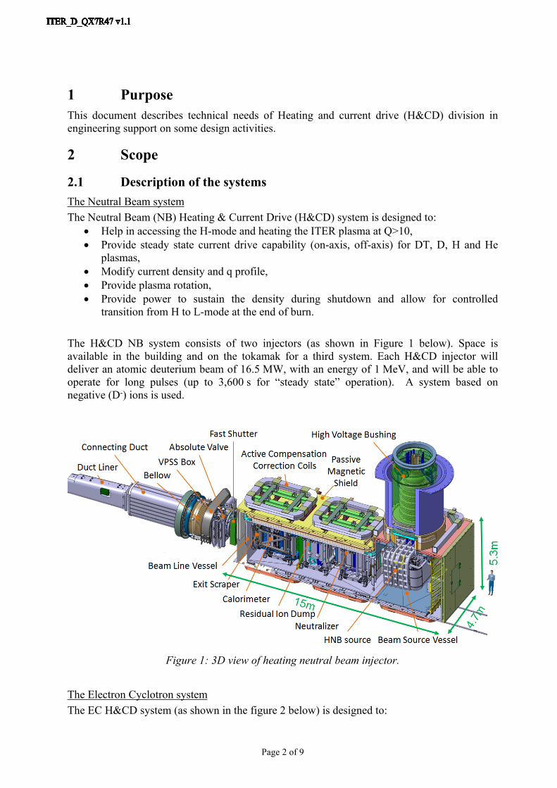
The H&CD NB system consists of two injectors (as shown in Figure 1 below). Space is available in the building and on the tokamak for a third system. Each H&CD injector will deliver an atomic deuterium beam of 16.5 MW, with an energy of 1 MeV, and will be able to operate for long pulses (up to 3,600 s for “steady state” operation). A system based on negative (D-) ions is used.
Figure 1: 3D view of heating neutral beam injector.
The Electron Cyclotron systemThe EC H&CD system (as shown in the figure 2 below) is designed to:

Page 3 of 9
Access H mode and heat plasma to Q>10. (with electron heating), Provide steady state current on-axis and off-axis drive, Control MHD instabilities by localized current drive, such as stabilization of neo-
classical tearing modes (NTMs) and sawtooth instability. Conduct wall conditioning during the inter-pulse and machine conditioning phase Assist the poloidal field system in establishing breakdown and current initiation
Figure 2: overall view of the EC system.
The EC H&CD system consists of:
24 Gyrotrons for H&CD (24MW installed power at 170 GHz with minimum pulse length of 3’600 sec),
12 Power supply sets for the above sources, 24 evacuated low-loss transmission including in-line, automatic and remotely
controlled switching system to share the RF power between the upper and equatorial launchers.
One equatorial launcher, Four upper launchers, Auxiliary systems (EC plant control and data acquisition system, cooling circuitry for
ex-vessel components, support structures, cubicles, HV enclosures, grounding plane).
The Ion Cyclotron systemThe IC H&CD system (as shown in the figure 3 below) is designed to:
Provide bulk RF heating of the plasma Assist accessing H mode and achieving Q=10 Assist plasma control (burn and transport) Provide on-axis current drive Provide ion current drive outside q=1 surface for sawtooth control
Page 4 of 9
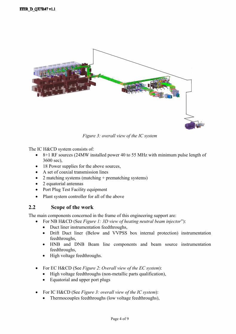
Figure 3: overall view of the IC system
The IC H&CD system consists of: 8+1 RF sources (24MW installed power 40 to 55 MHz with minimum pulse length of
3600 sec), 18 Power supplies for the above sources, A set of coaxial transmission lines 2 matching systems (matching + prematching systems) 2 equatorial antennas Port Plug Test Facility equipment Plant system controller for all of the above
2.2 Scope of the workThe main components concerned in the frame of this engineering support are:
For NB H&CD (See Figure 1: 3D view of heating neutral beam injector”): Duct liner instrumentation feedthroughs, Drift Duct liner (Below and VVPSS box internal protection) instrumentation
feedthroughs, HNB and DNB Beam line components and beam source instrumentation
feedthroughs, High voltage feedthroughs.
For EC H&CD (See Figure 2: Overall view of the EC system): High voltage feedthroughs (non-metallic parts qualification), Equatorial and upper port plugs
For IC H&CD (See Figure 3: overall view of the IC system): Thermocouples feedthroughs (low voltage feedthroughs),
Page 5 of 9
RF and Langmuir probes feedthroughs
The objective of this engineering contract is to support the H&CD teams in the: Review the feedthroughs required for the H&CD system, developing a minimum subset
compliant with the NB, EC and IC needs Develop the associated feedthrough designs Develop the design requirements and associated documentation of said feedthroughs Develop the testing and qualification programme Follow up of the associated ITA under which the qualification will be performed. The tasks will be performed in the scope of ITAs with F4E (C52TD50FE and
C52TD51FE).
3 DefinitionsEC: Electron CyclotronH&CD: Heating and Current DriveIC: Ion CyclotronIO: ITER organizationITA: ITER Task AgreementNB: Neutral BeamNBI: Neutral Beam InjectorSDC-IC: Structural design Criteria – In vessel Components
4 ReferencesNot applicable.
5 Estimated DurationThe duration shall be 12 months from the starting date of the contract, will be fully based at IO. An extension by another year is expected to Participation to meetings outside the IO could be envisaged.
6 Work DescriptionTask 1: Coordinate HCD Feedthrough Design Development:A design for instrumentation feedthroughs exists which is compliant with the NB system requirements. However this design has not yet been qualified for primary confinement. The purpose of this contract is to develop the required list of feedthroughs necessary for the 3 HCD systems and to investigate the possibility of using the NB feedthrough design as the basis of all feedthroughs in order to limit the prototyping required. An ITA launched with F4E C52TD50FE will be used to develop the prototypes and perform the associated tests for the specific feedthroughs as required for the NB Injector, IC Antenna and EC Launchers. This includes the signal, mm-wave, coolant, electrical, and pneumatic actuators. The majority of these feedthroughs are specific to the ITER H&CD systems, and F4E is asked to develop the design and prototype tests of these feedthroughs with the other scope of works within F4E’s procurements. In parallel, IO will coordinate with F4E, and the
Page 6 of 9
relevant DAs to develop a feedthrough catalogue (in the scope of this work), such that the output of this effort can be utilised globally.
Task 2: Coordinate HCD Feedthrough Qualification Plan
This work is necessary because the different types of feedthroughs will use materials and/or manufacturing processes not covered by nuclear and design manufacturing codeA qualification approach by experiment is foreseen and shall be defined to check the structural integrity of the design under the different ITER load cases. It is then necessary to define a set of tests and inspections demonstrating compliance of the proposed design with requirements specified in the associated design requirement document and loads from load specification. The contractor will have also to define all acceptance criteria to be respected during tests.
This plan will be used to demonstrate acceptability and reliability of the feedthroughs design to Nuclear Safety Authority.
The contractor will have to interact with all involved parties in IO and/or DAs in the preparation of this plan.
7 ResponsibilitiesNot applicable.
8 List of deliverables and due dates Conceptual design report: for each feedthrough: The aim of this document is to
describe design proposal for each feedthrough. At this stage, the design proposals are based on catalogues components as much as possible and agreed by each system RO.
CAD integration report: The aim of this document is to describe integration of all required feedthroughs on each system assessing the possibility to have common design or not for them. CAD work will be performed by an ITER designer but engineer will have to follow up the task and support the designer.
Design Requirements Documents: the aim of this document is to collect and describe all requirements driving the design of the feedthroughs.
Load specifications: the aim of this document is to describe all the loads driving the design of the feedthroughs
Preliminary design report: the aim of this document is to describe the design at an advanced stage. It must demonstrate manufacturability and ensure that major design constraints are solved. Here also the engineer will be helped by a ITER engineer.
Qualification plan: the aim of this document is to describe all tests to be performed and all acceptance criteria in order to qualify the feedthroughs.
Design report and analysis report: the aim of this document is to describe the design choices and the supporting analyses. Both must demonstrate the compliance between design requirements, loads and interfaces with the design proposed. It shall also include 2D drawings of each feedthrough.
Page 7 of 9
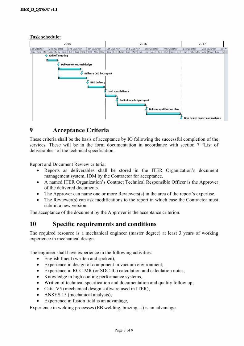
Task schedule:
9 Acceptance CriteriaThese criteria shall be the basis of acceptance by IO following the successful completion of the services. These will be in the form documentation in accordance with section 7 “List of deliverables” of the technical specification.
Report and Document Review criteria: Reports as deliverables shall be stored in the ITER Organization’s document
management system, IDM by the Contractor for acceptance. A named ITER Organization’s Contract Technical Responsible Officer is the Approver
of the delivered documents. The Approver can name one or more Reviewers(s) in the area of the report’s expertise. The Reviewer(s) can ask modifications to the report in which case the Contractor must
submit a new version. The acceptance of the document by the Approver is the acceptance criterion.
10 Specific requirements and conditionsThe required resource is a mechanical engineer (master degree) at least 3 years of working experience in mechanical design.
The engineer shall have experience in the following activities: English fluent (written and spoken), Experience in design of component in vacuum environment, Experience in RCC-MR (or SDC-IC) calculation and calculation notes, Knowledge in high cooling performance systems, Written of technical specification and documentation and quality follow up, Catia V5 (mechanical design software used in ITER), ANSYS 15 (mechanical analysis), Experience in fusion field is an advantage,
Experience in welding processes (EB welding, brazing…) is an advantage.

Page 8 of 9
11 Work Monitoring / Meeting ScheduleThe work will be managed by means of Progress Meetings and/or formal exchange of documents transmitted by emails which provide detailed progress. Progress Meetings will be called by the ITER Organization, to review the progress of the work, the technical problems, the interfaces and the planning.
The main purpose of the Progress Meetings is to allow the ITER Organization/Neutral beam section and the Contractor Technical Responsible Officers to:
a) Allow early detection and correction of issues that may cause delays;b) Review the completed and planned activities and asses the progress made;c) Permit fast and consensual resolution of unexpected problems;
Clarify doubts and prevent misinterpretations of the specifications.
12 Delivery time breakdownInterim payments may be processed quarterly upon the satisfactory completion of the work in accordance with the deliverables in section 7 on the technical specification “Deliverables and due dates”.
Four equal payments will be made by IO upon submission and IO approval of the corresponding deliverables in accordance with the deliverables in section 7 on the technical specification and upon receipt of a correctly rendered invoice.
13 Quality Assurance (QA) requirementsThe organisation conducting these activities should have an ITER approved QA Program or an ISO 9001 accredited quality system.The general requirements are detailed in ITER Procurement Quality Requirements (ITER_D_22MFG4).Prior to commencement of the task, a Quality Plan must be submitted for IO approval giving evidence of the above and describing the organisation for this task; the skill of workers involved in the study; any anticipated sub-contractors; and giving details of who will be the independent checker of the activities (see Procurement Requirements for Producing a Quality Plan (ITER_D_22MFMW)).Documentation developed as the result of this task shall be retained by the performer of the task or the DA organization for a minimum of 5 years and then may be discarded at the direction of the IO. The use of computer software to perform a safety basis task activity such as analysis and/or modelling, etc. shall be reviewed and approved by the IO prior to its use, in accordance with Quality Assurance for ITER Safety Codes (ITER_D_258LKL).
14 CAD Design Requirements (if applicable)For the contracts where CAD design tasks are involved, the following shall apply:The Supplier shall provide a Design Plan to be approved by the IO. Such plan shall identify all design activities and design deliverables to be provided by the Contractor as part of the contract.
Page 9 of 9
The Supplier shall ensure that all designs, CAD data and drawings delivered to IO comply with the Procedure for the Usage of the ITER CAD Manual (2F6FTX), and with the Procedure for the Management of CAD Work & CAD Data (Models and Drawings 2DWU2M).The reference scheme is for the Supplier to work in a fully synchronous manner on the ITER CAD platform (see detailed information about synchronous collaboration in the ITER GNJX6A - Specification for CAD data production in ITER Contracts.). This implies the usage of the CAD software versions as indicated in CAD Manual 07 - CAD Fact Sheet (249WUL) and the connection to one of the ITER project CAD data-bases. Any deviation against this requirement shall be defined in a Design Collaboration Implementation Form (DCIF) prepared and approved by DO and included in the call-for-tender package. Any cost or labour resulting from a deviation or non-conformance of the Supplier with regards to the CAD collaboration requirement shall be incurred by the Supplier.
15 Safety requirementsITER is a Nuclear Facility identified in France by the number-INB-174 (“Installation Nucléaire de Base”).For Protection Important Components and in particular Safety Important Class components (SIC), the French Nuclear Regulation must be observed, in application of the Article 14 of the ITER Agreement.In such case the Suppliers and Subcontractors must be informed that:
- The Order 7th February 2012 applies to all the components important for the protection (PIC) and the activities important for the protection (PIA).
- The compliance with the INB-order must be demonstrated in the chain of external contractors.
- In application of article II.2.5.4 of the Order 7th February 2012, contracted activities for supervision purposes are also subject to a supervision done by the Nuclear Operator.
For the Protection Important Components, structures and systems of the nuclear facility, and Protection Important Activities the contractor shall ensure that a specific management system is implemented for his own activities and for the activities done by any Supplier and Subcontractor following the requirements of the Order 7th February 2012 [20].