technical specifications (in-cash procurement)...
TRANSCRIPT

PDF generated on 07 Oct 2014DISCLAIMER : UNCONTROLLED WHEN PRINTED – PLEASE CHECK THE STATUS OF THE DOCUMENT IN IDM
Technical Specifications (In-Cash Procurement)
Techncial Specification - Call for Expertise: Structural Analysis
This technical specification is to describe the scope of work to be provided by the Supplier to the ITER Organisation (IO) Vacuum Section.The purpose of this contract is to perform analyses on components of the ITER Vacuum system:The Torus, Cryostat and Neutral Beam Cryopumps and the related installation and maintenance tools.The all metal vacuum valves used for the ITER Vacuum System. Support structures for vacuum valves mounted to piping.
Approval Process Name Action AffiliationAuthor Dremel M. 06 Oct 2014:signed IO/DG/DIP/PSE/FCED/VSCo-AuthorsReviewers Dremel M. 06 Oct 2014:recommended IO/DG/DIP/PSE/FCED/VSPrevious Versions Reviews
Pearce R. 29 Sep 2014:recommended v1.0 IO/DG/DIP/PSE/FCED/VS
Approver Pearce R. 07 Oct 2014:approved IO/DG/DIP/PSE/FCED/VSDocument Security: Internal Use
RO: Pearce RobertRead Access RO, project administrator, LG: Manfred Glugla, LG: Kim Yong-Hwan, LG: PA 3.1.Px.US.xx DA PA PT,
LG: Contracts, AD: ITER, AD: IO_Director-General, AD: IC_OMPE_WG, AD: Section - Vacuum - EXT, AD: Section - Vacuum, AD: Auditors, AD: ITER Management Assessor
IDM UID
Q2CFH5VERSION CREATED ON / VERSION / STATUS
06 Oct 2014 / 1.1 / Approved
EXTERNAL REFERENCE
PDF generated on 07 Oct 2014DISCLAIMER : UNCONTROLLED WHEN PRINTED – PLEASE CHECK THE STATUS OF THE DOCUMENT IN IDM
Change Log
Title (Uid) Version Latest Status Issue Date Description of Change
Techncial Specification - Call for Expertise: Structural Analysis (Q2CFH5_v1_1)
v1.1 Approved 06 Oct 2014
Changes incorporated following review by PCD:
Section 5 - Section title changed for consistency
Section 5 - 'Knowledge of ITER Project ....an advantage' removed.
Techncial Specification - Call for Expertise: Structural Analysis (Q2CFH5_v1_0)
v1.0 Approved 29 Sep 2014
First version
Techncial Specification - Call for Expertise: Structural Analysis (Q2CFH5_v0_0)
v0.0 In Work 12 Sep 2014
Table of Contents
1 Abstract................................................................................................................................22 Background and Objectives ...............................................................................................2
2.1 All Metal Vacuum Gate Valves .................................................................................22.2 The ITER Torus and Cryostat Cryopumps .............................................................4
3 Scope of Work .....................................................................................................................54 Estimated Duration.............................................................................................................65 Specific Requirements ........................................................................................................66 Work Description................................................................................................................67 Responsibilities....................................................................................................................88 Deliverables .........................................................................................................................8
8.1 Acceptance Criteria ..................................................................................................109 Work Monitoring / Meeting Schedule.............................................................................10
9.1 Progress Reports .......................................................................................................1110 Payment Schedule .............................................................................................................1111 Task Management.............................................................................................................11
11.1 Resources ...................................................................................................................1111.2 Information and Documentation Management......................................................11
12 Regulatory Requirements ................................................................................................1213 Quality Assurance.............................................................................................................12
13.1 Quality Plan...............................................................................................................1213.1.1 Deviations and Non-Conformances....................................................................1313.1.2 Documentation....................................................................................................13
14 References..........................................................................................................................1315 List of Acronyms...............................................................................................................14

Page 2 of 15
1 AbstractThis technical specification is to describe the scope of work to be provided by the Supplier to the ITER Organisation (IO) Vacuum Section.
The purpose of this contract is to perform analyses on components of the ITER Vacuum system:
1. The all metal vacuum valves used for the ITER Vacuum System.2. The Torus, Cryostat and Neutral Beam Cryopumps and the related installation and
maintenance tools.3. Support structures for vacuum piping and standard vacuum equipment.
Some of these components will perform some safety functions and are classified as Protection Important Components (PIC). As a result, specific quality assurance requirements must be applied as described in Sections 12 and 13.
2 Background and ObjectivesITER will be the largest and most complex vacuum system yet to be built. Situated in Southern France, adjacent to the French CEA Cadarache site, the ITER facility covers approximately 190 hectares and is designed to study the fusion reaction between the hydrogen isotopes tritium and deuterium.
The machine is normally operated under vacuum conditions, and a large number of all metal valves are used to control the machine. The ITER Organization needs to demonstrate the design maturity of these valves under the very specific ITER load conditions.
The main volumes of the device are pumped by tailor made cryogenic pumps which need to undergo detailed structural analyses during the design phase for all operational loads and accidental conditions.
The objectives of this contract are to provide the ITER Organization with mechanical engineering services regarding structural and thermal analyses.
2.1 All Metal Vacuum Gate Valves
Different vacuum valves are used on the ITER machine and shall be mechanically analysed to cope with all ITER load cases.
Valve Type Description Flange Option (Nominal valve size, DN)

Page 3 of 15
Figure 1 - Sectional cut through an all metal valve (example) to show internal design
1
Pneumatic double contained UHV all-metal gate valves with all-metal seat sealing, double contained body, bellows and bonnet seal.
Weld stub or ITER flange (40,63,100,160,200,320)
2Pneumatic UHV all-metal gate valves with all-metal seat and bonnet seal. Weld stub or CF flange (40,63,100,160,200)
3
Pneumatic all-metal UHV special gate valves with all-metal seat, double contained bellows and bonnet seal.
Special valves
4
Pneumatic Double contained right angle UHV valve with all-metal seat and bonnet seal and double contained bellows. (with weld stub or ITER Flange)
Weld stub or ITER Flange (40,63)
Page 4 of 15
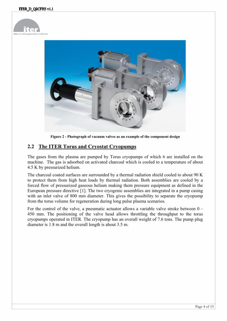
Figure 2 - Photograph of vacuum valves as an example of the component design
2.2 The ITER Torus and Cryostat Cryopumps
The gases from the plasma are pumped by Torus cryopumps of which 6 are installed on the machine. The gas is adsorbed on activated charcoal which is cooled to a temperature of about 4.5 K by pressurized helium.
The charcoal coated surfaces are surrounded by a thermal radiation shield cooled to about 90 K to protect them from high heat loads by thermal radiation. Both assemblies are cooled by a forced flow of pressurized gaseous helium making them pressure equipment as defined in the European pressure directive [1]. The two cryogenic assemblies are integrated in a pump casing with an inlet valve of 800 mm diameter. This gives the possibility to separate the cryopump from the torus volume for regeneration during long pulse plasma scenarios.
For the control of the valve, a pneumatic actuator allows a variable valve stroke between 0 – 450 mm. The positioning of the valve head allows throttling the throughput to the torus cryopumps operated in ITER. The cryopump has an overall weight of 7.6 tons. The pump plug diameter is 1.8 m and the overall length is about 3.5 m.

Page 5 of 15
Figure 3 – View of a sectional cut of the torus cryopump CAD model
The six torus cryopumps (TCP) are located on the lower ports of the Vacuum Vessel (VV). All TCP are located on direct extensions of the lower port (4, 6, 10, 12, 16, 18), see figure 4.
Figure 4- TCP installed in the Torus Cryopump Housing (TCPH) and connection to VV
Page 6 of 15
The cryopumps are designed by analysis based on stress categories. This methodology is outlined in EN 13445-3 Annex C [1] and the structural analyses of the cryopumps shall be in accordance with this standard.
3 Scope of Work The scope of work is to provide the ITER Organization with engineering services in order to complete the analyses of components of the ITER Vacuum system. The scope of work is made up of 3 work packages as follows:
1. The all metal vacuum valves used for the Vacuum System:
a. Valve Type 1 (PIC): Pneumatic double contained UHV all-metal gate valves with all-metal seat sealing, double contained body, bellows and bonnet seal. Weld stub or ITER flange (40,63,100,160,200,320)
b. Valve Type 2 (non-PIC): Pneumatic UHV all-metal gate valves with all-metal seat and bonnet seal. Weld stub or CF flange (40,63,100,160,200)
c. Valve Type 3 (PIC): Pneumatic all-metal special gate valves with all-metal seat, double contained bellows and bonnet seal.
d. Valve Type 5 (PIC): Pneumatic Double contained right angle UHV valve with all-metal seat and bonnet seal and double contained bellows. (with weld stub or ITER Flange) Weld stub or ITER Flange (40,63)
2. The Torus, Cryostat and Neutral Beam Cryopumps and the related installation and maintenance tools.
3. Support structures for vacuum piping and standard vacuum equipment.
Currently, no vacuum valves exist which have been qualified to meet their safety functions in the context of the ITER Project. The analyses of the all metal valves (work package 1) will therefore be a priority and, due to the complexities involved, this will require some iteration as described in Section 6. Some flexibility will therefore be required between the work packages and this will be agreed in advance by the IO as described in Section 9.
4 Estimated DurationThe program of work shall be for a maximum of 250 days over a maximum 15 month period, with an option to extend for a further 15 month period. The contract shall be executed by one dedicated expert analyst who shall be required on the IO site for the duration of the contract.
5 Specific RequirementsThe analyst shall have the experience and qualifications as provided below:
Master of Science in mechanical engineering At least 6 years of professional working experience At least 2 to 3 years of experience in Structural Finite Element Analysis (linear and
non-linear)
Page 7 of 15
Good engineering experience to develop and detail load conditions The cryopumps are designed according to the European pressure vessel code EN
13445 [1]. A professional knowledge of the design method “Design by Analysis (DBA) - Method Based on Stress Categories” described in Annex C of EN13445-3 is required.
Experience and knowledge of the concepts for cryogenic pump design cooled by forced flow of pressurized helium. This shall include simulation of sliding contacts, assemblies for thermal insulation and radiation heat loads.
Knowledge of engineering calculations, mechanics, strength of stainless steel and aluminium is required and knowledge of material properties at cryogenic temperatures.
Experience in ANSYS software (Mechanical/Workbench/CFX) is mandatory. Base knowledge of the use of CATIA to view input data is required. Experience in the preparation of analysis reports is required. Experience in the analysis of nuclear components. Sufficient experience to deliver the scope of work with independent autonomy. Fluency in English both verbal and written is required.
6 Work DescriptionThe purpose of the work is to demonstrate, through detailed analyses, that components do not experience certain types of structural damage when subjected to the postulated loading conditions and that their performance is maintained:
The structural analysis consists of verifying compliance with criteria based on the analysis method considering the event category (I, II, III & IV) and the type of allowable damage as outlined in the Design Basis following the ITER guideline for structural analyses [5].
The thermal stresses in the different operational modes of the systems need to be carefully investigated to demonstrate that no structural damage occurs and, for some components, the functioning needs to be demonstrated on a case by case basis.
In the case of the structural analyses for the valves, the maximum allowable mechanical loads shall be determined.
The analyses should be done using ANSYS Mechanical/Workbench software for all structural assessments.
Some hand calculation can be envisaged, but the demonstration must be robust and its use will be subject to the acceptance of the IO Technical Responsible Officer (TRO).
The analysis method should follow the steps below:
1. Preparation of analysis model: The analysis model shall be based on the CAD model delivered by IO under the responsibility of the IO TRO. Geometry cleaning and simplification should be performed in order to obtain 3D solid element meshing with a good size/precision ratio.
Page 8 of 15
Proposals for model simplifications with shells and beam elements, if properly justified, can be discussed and validated with IO TRO.
2. Damages prevention by structural analyses:Failure modes to be checked in the analysis are gross plastic deformation and progressive plastic deformation. Accordingly, the following analyses are expected: elastic analyses based on stress categorization to determine primary stress levels for category I, II, III & IV events and secondary stress levels for category I & II events. Bolt preload should be applied and a detailed description of selected contact surfaces should be provided and validated by IO. If necessary, complementary calculations will be performed to check instability (buckling) and fatigue (considering the cyclic loads).
3. Single & combined loads: The System Load Specifications [2], [3], [4] will be supplied by IO. Before getting new results of loads, the analyst can prepare the analysis model first and perform test analyses with previous loads. The previous loads will also be supplied by IO. Loads to be considered will be:
a. Inertial (Gravity, Seismic loads )b. Pressurec. Thermal (steady-state and/or transient) resulting from conduction, convection
and/or radiationd. Listed combinations of the above loads
Two distinct system configurations will be considered: In Operation During Installation/Assembly
Load levels depend on the loading conditions (normal operation, exceptional events, proof test).
Input data to be provided by IO:
Geometry: CAD and/or other models Loads (Refer to the Load specifications [2], [3], [4] and additional Memos) Material data
Output data to be produced by the Supplier:Unless otherwise agreed, the main output shall be updated models and comprehensive reports which include the methodology and all the results of the analyses including tables and figures illustrating the mechanical reactions and the distribution of stresses, strains and displacements in the analysed part at all applied loads and load combinations.
For each valve type, an analysis of the body shall be carried out. This shall be followed by a detailed analysis including the internal assemblies for different operational states. Due to the complexity, the analysis of the first valve of each type will be reviewed by the IO prior to the continuation of the analyses for the remaining valves of this valve type. For the PIC valves, one report for each valve shall be prepared. For non-PIC valves one common report shall be delivered.
Page 9 of 15
The deliverables required as a result of this contract together with the acceptance criteria are provided in detail below in Section 8.
7 Responsibilities ITER Organisation:
IO will provide all the required information and access to the appropriate ITER files for executing this work. In particular, IO will make available any technical information, including 3D models, layouts and drawings, input data for the loads, references, etc. as needed for the Supplier to perform the work.
Supplier:
The Supplier shall appoint a responsible person who shall represent the Supplier for all matters related to the implementation of this contract.
The Supplier’s analyst will perform analyses and provide results according to the scope of the work outlined above. In some cases, an assessment of the preliminary design can be envisaged and an improvement of the design proposed if needed.
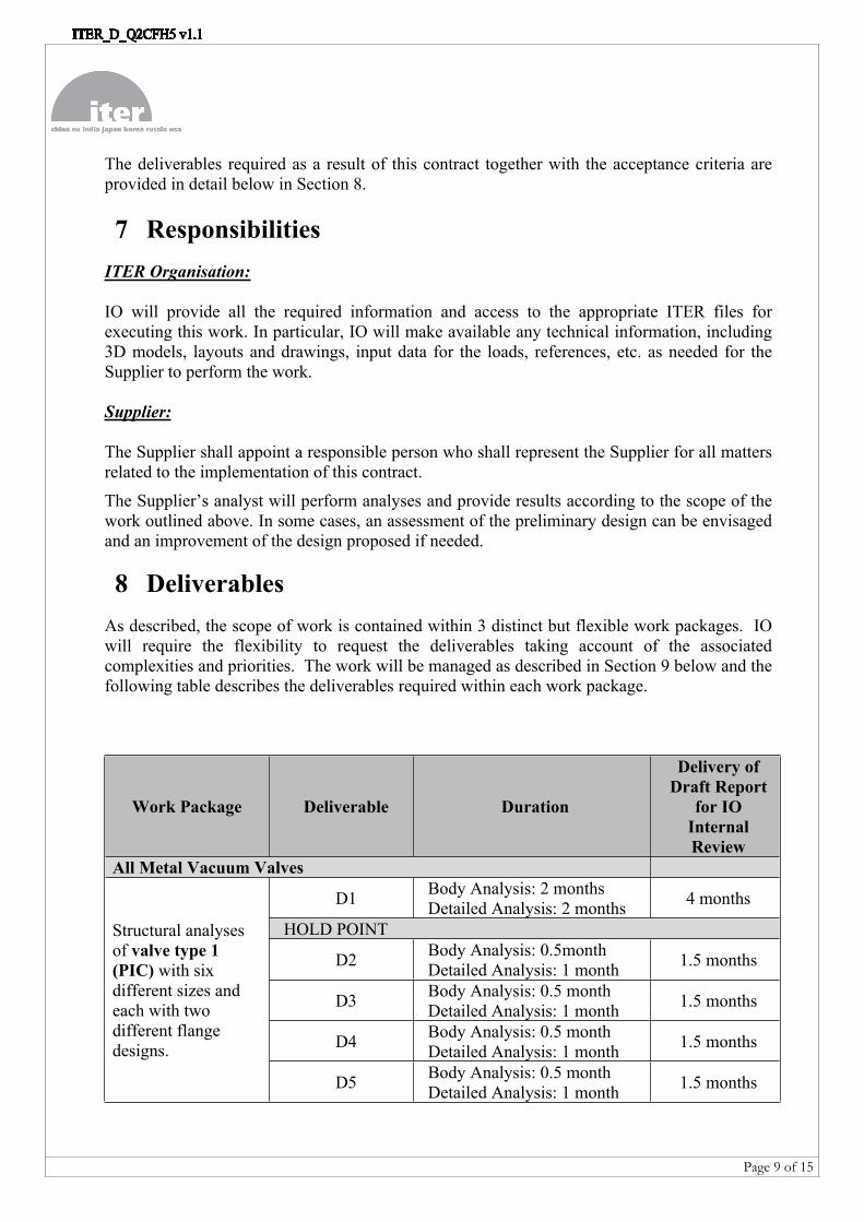
8 DeliverablesAs described, the scope of work is contained within 3 distinct but flexible work packages. IO will require the flexibility to request the deliverables taking account of the associated complexities and priorities. The work will be managed as described in Section 9 below and the following table describes the deliverables required within each work package.
Work Package Deliverable Duration
Delivery of Draft Report
for IO Internal Review
All Metal Vacuum Valves
D1 Body Analysis: 2 monthsDetailed Analysis: 2 months 4 months
HOLD POINT
D2 Body Analysis: 0.5monthDetailed Analysis: 1 month 1.5 months
D3 Body Analysis: 0.5 monthDetailed Analysis: 1 month 1.5 months
D4 Body Analysis: 0.5 monthDetailed Analysis: 1 month 1.5 months
Structural analyses of valve type 1 (PIC) with six different sizes and each with two different flange designs.
D5 Body Analysis: 0.5 monthDetailed Analysis: 1 month 1.5 months
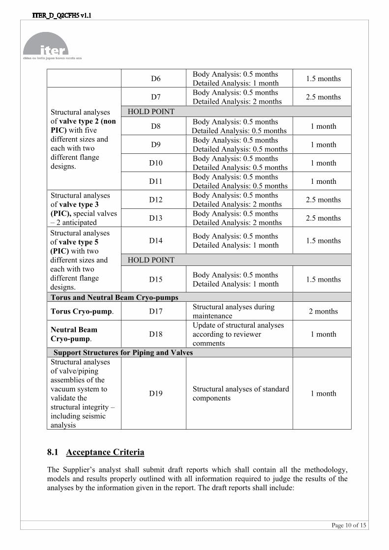
Page 10 of 15
D6 Body Analysis: 0.5 monthsDetailed Analysis: 1 month 1.5 months
D7 Body Analysis: 0.5 monthsDetailed Analysis: 2 months 2.5 months
HOLD POINT
D8 Body Analysis: 0.5 months Detailed Analysis: 0.5 months 1 month
D9 Body Analysis: 0.5 monthsDetailed Analysis: 0.5 months 1 month
D10 Body Analysis: 0.5 monthsDetailed Analysis: 0.5 months 1 month
Structural analyses of valve type 2 (non PIC) with five different sizes and each with two different flange designs.
D11 Body Analysis: 0.5 monthsDetailed Analysis: 0.5 months 1 month
D12 Body Analysis: 0.5 monthsDetailed Analysis: 2 months 2.5 monthsStructural analyses
of valve type 3 (PIC), special valves – 2 anticipated D13 Body Analysis: 0.5 months
Detailed Analysis: 2 months 2.5 months
D14 Body Analysis: 0.5 monthsDetailed Analysis: 1 month 1.5 months
HOLD POINT
Structural analyses of valve type 5 (PIC) with two different sizes and each with two different flange designs.
D15 Body Analysis: 0.5 monthsDetailed Analysis: 1 month 1.5 months
Torus and Neutral Beam Cryo-pumps
Torus Cryo-pump. D17 Structural analyses during maintenance 2 months
Neutral Beam Cryo-pump. D18
Update of structural analyses according to reviewer comments
1 month
Support Structures for Piping and ValvesStructural analyses of valve/piping assemblies of the vacuum system to validate the structural integrity – including seismic analysis
D19 Structural analyses of standard components 1 month
8.1 Acceptance Criteria
The Supplier’s analyst shall submit draft reports which shall contain all the methodology, models and results properly outlined with all information required to judge the results of the analyses by the information given in the report. The draft reports shall include:
Page 11 of 15
Summary of the input data Boundary conditions applied List of all investigated load cases Explanation of the methodology Engineering summary with maximum stress, margins to the allowable stresses. Statement of compliance or non- compliance to a load case. Results.
All the methodology and assessments must be fully consistent with the Codes & Standards defined in the scope of work and as instructed by the IO TRO. All the related articles must be clearly referenced. All reports, models and macros should be saved in the IO Document Management System (IDM) as electronic data.
Hold Points
For work package 1, all metal valves, there will be a Hold Point to allow the analysis of the first valve of each type to be reviewed by the IO prior to the continuation of the analyses for the remaining valves of this valve type.
The IO Technical Responsible Officer shall review the draft deliverables and shall provide comments within 10 days. The Supplier’s analyst shall perform all the necessary modifications or iterations to the deliverables and submit a revised version for acceptance by the IO TRO within 1 week. The final deliverables shall include:
Final reports based on the draft reports including all the IO comments concerning the draft deliverables for final approval by the IO TRO.
Analysis models shall be stored in the ITER database Macros (APDL) to apply loads on the models.
9 Work Monitoring / Meeting ScheduleThe work will be managed by means of informal weekly progress meetings and formal monthly progress reports. In addition, a meeting will be held to discuss and review each draft deliverable.
The weekly progress meetings will be called by the ITER Organization and will be held in informal free discussion style to review the progress of the work, the technical problems, the interfaces and the planning. The main purpose of these meetings is to allow the IO TRO and the Supplier’s analyst to:
i) Detect early any issues that may cause delays and to agree corrective action.ii) Review the completed and planned activities and asses the progress made.iii) Permit fast and consensual resolution of unexpected problems.iv) Clarify doubts and prevent misinterpretations of the specifications.
In addition to the weekly progress meetings, the formal exchange of information and documents will be achieved by email.
Further meetings will also be held to discuss and review each draft deliverable.
If necessary, the IO TRO and/or the Supplier may request additional formal progress meetings to address specific issues to be resolved.

Page 12 of 15
9.1 Progress Reports
For the weekly progress meetings, the Supplier should produce and provide a short report which summarises the points discussed and the actions agreed. This may be in the form of an email but should be provided to the IO TRO for approval.
Formal monthly Progress Reports shall be submitted to the IO TRO in accordance with the Supplier’s Quality Plan (see Section 13). As a minimum, each report shall include:
Current status of each deliverable Progress against plan including the number of days spent Any issues or problems to be solved Update of the status of all outstanding actions
All the documents or data prepared for any meeting (progress or otherwise), shall be saved in IDM by the Supplier to maintain a clear audit trail.
10 Payment SchedulePayment will be made on a monthly basis following the delivery and approval of the monthly Progress Reports.
11 Task Management11.1 Resources
The Supplier shall provide a dedicated resource for this contract who shall be based on the IO site. This analyst shall not be replaced without the prior written approval of IO.
11.2 Information and Documentation Management
All correspondence and documentation related to the execution of the contract including, but not limited to, all intermediate and final reports shall be stored and managed using IDM.
12 Regulatory RequirementsITER is a licensed nuclear facility as defined in the Decree of Authorisation of Creation of ITER-INB-174 [6] and consequently IO, the Nuclear Operator, must comply with the French Order of 7th February 2012 which provides the regulatory framework for licensed nuclear installations (INB-Order) [7].
Certain components, structures and systems of ITER are classified as important for the interests of public safety as defined under Article L 593-1 of the French Environmental Code [8] and are further classified according to the area or service (i.e. their function).
Some components included in this Technical Specification will perform some safety functions and hence, under the scope of the INB-Order, these are classified as Protection Important Components (PIC). As a result, some of the activities required in this Technical Specification
Page 13 of 15
are similarly classified as Protection Important Activities (PIA) and specific quality assurance requirements must be applied.
The IO as Operator is responsible for ensuring that Protection Important Components are qualified, supplied and applied to meet their safety functions in compliance with their associated safety requirements and under the requirements of the INB-Order [7].
The Supplier must demonstrate compliance with the provisions for the implementation of the INB Order [7] including the defined requirements (articles 2.5.1 and 2.5.2) in their organisation and in the chain of subcontractors.
13 Quality Assurance The Supplier’s Quality Assurance Programme (QAP) is subject to approval by the IO in accordance with the ITER QA Programme and shall be applied to all work carried out as a result of any contract arising from this Specification.
The ITER QA Programme is based on IAEA Safety Standard GS-R-3 and on conventional QA principles and integrates the requirements of the INB Order [7] on the quality of design, construction and operation of licensed nuclear installations. For this purpose, the Supplier shall ensure that any subcontractors carrying out work placed under the prime contract are in compliance with the QA requirements under the relevant QA classifications.
The general requirements are detailed in ITER Integrated Safety, Quality and Security Policy [9], and ITER Procurement Quality Requirements [10]. The specific requirements for the supervision of all subcontractors in the supply chain for Protection Important Components, Structures, Systems and Activities are detailed in [11].
13.1 Quality Plan
Prior to commencement of the work, a Quality Plan [12] must be submitted for IO approval giving evidence of the above and describing the organisation for this work; the qualification and experience of the workers involved including named individual(s) who will act as Independent Reviewer(s) and Checkers(s) and any anticipated subcontractors.
The use of computer software to perform a safety based task or activity such as analysis and/or modelling shall be reviewed and approved by the IO prior to its use, in accordance with [13].
13.1.1Deviations and Non-Conformances
A deviation is defined in the Order [7] as a non-compliance with a defined requirement or non-compliance with a requirement set by the licensee’s integrated management system that could affect the provisions of the Environment Code [8].
All deviations and non-conformities must strictly follow the procedure detailed in ITER Requirements Regarding Contractors Deviations and Non Conformities [14].
The overriding principle is to ensure timely identification and review of deviations and non-conformances in order to determine the importance and to ensure appropriate corrective action
Page 14 of 15
is taken. The management of deviations and non-conformances and the analysis of trends is also part of the overall IO Project continuous improvement process
13.1.2Documentation
All documentation related to the design, construction, manufacturing, commissioning, assembly, maintenance and surveillance of a PIC must be provided to the IO.
14 References[1] EN13445 - Unfired Pressure Vessels[2] System Load Specification for Torus Cryopump (ITER_D_EU4B2V)[3] Load Specifications (ITER_D_222QGL)[4] System Load Specification of the Neutral Beam Cryopumps (ITER_D_HTU85R)[5] ITER Guideline for structural analyses (ITER_D_35BVV3)[6] Decree No. 2012-1248 dated 9 November 2012 authorising IO to create a basic nuclear
facility called « ITER » - EN (ITER_D_CZK7M5).[7] Order dated 7 February 2012 relating to the general technical regulations applicable to
INB – EN (ITER_D_7M2YKF).[8] Environmental Code. Ordinance 2000/914 dated 18 September 2000. As amended.
Available: http://www.legifrance.gouv.fr [9] ITER Integrated Safety, Quality and Security Policy (ITER_D_43UJN7)[10] ITER Procurement Quality Requirements (ITER_D_22MFG4)[11] Overall Supervision Plan of External Interveners Chain for Protection Important
Components, Structures and Systems and Protection Important Activities (ITER_D_4EUQFL)
[12] Procurement Requirements for Producing a Quality Plan (ITER_D_22MFMW)[13] Quality Assurance for ITER Safety Codes (ITER_D_258LKL)[14] MQP Deviations and Non Conformities (ITER_D_22F53X)
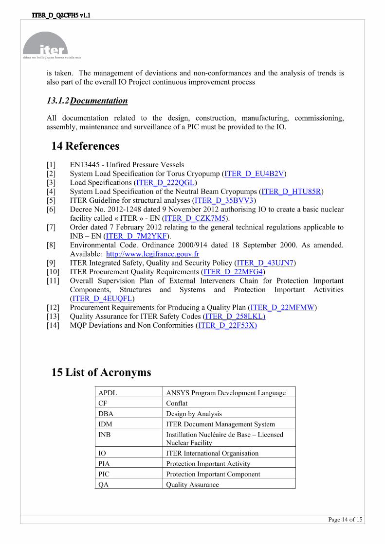
15 List of AcronymsAPDL ANSYS Program Development LanguageCF ConflatDBA Design by AnalysisIDM ITER Document Management System INB Instillation Nucléaire de Base – Licensed
Nuclear FacilityIO ITER International OrganisationPIA Protection Important ActivityPIC Protection Important ComponentQA Quality Assurance
Page 15 of 15
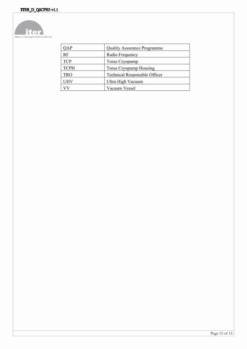
QAP Quality Assurance ProgrammeRF Radio FrequencyTCP Torus CryopumpTCPH Torus Cryopump HousingTRO Technical Responsible OfficerUHV Ultra High VacuumVV Vacuum Vessel