technical instructions for safety recall jlb high …
TRANSCRIPT

TECHNICAL INSTRUCTIONS
FOR
SAFETY RECALL JLB
High Pressure Fuel Pumps
CERTAIN 2015 - 2018 RC-F CERTAIN 2016 – 2018 GS-F
CERTAIN 2018 LC 500
The repair quality of covered vehicles is extremely important to Lexus. All dealership technicians performing this recall are required to successfully complete the most current version of the E-Learning course “Safety Recall and Service Campaign Essentials”. To ensure that all vehicles have the repair performed correctly; technicians performing this recall repair are required to currently hold at least one of the following certification levels:
• Certified
• Senior
• Master It is the dealership’s responsibility to select technicians with the above certification level or greater to perform this recall repair. Carefully review your resources, the technician skill level, and ability before assigning technicians to this repair. It is important to consider technician days off and vacation schedules to ensure there are properly trained technicians available to perform this repair at all times.

2
I. OPERATION FLOW CHART
II. IDENTIFICATION OF AFFECTED VEHICLES
• Check the TIS Vehicle Inquiry System to confirm the VIN is involved in this Safety Recall, and that it has not already been completed prior to dealer shipment or by another dealer.
• TMS warranty will not reimburse dealers for repairs completed on vehicles that are not affected or were completed by another dealer.
III. PREPARATION
A. PARTS
Part Number Part Description Quantity 04007-60136 PUMP KIT, FUEL 1
*The kit above includes the following parts:
Part Number Part Description Quantity 23021-38020 PUMP SUB-ASSY, FUEL W/SEAL 1
23021-38030 PUMP SUB-ASSY, FUEL W/SEAL 1
23224-36010 GASKET, FUEL PUMP SPACER 2
11159-38010 GASKET. CAMSHAFT BEARING CAP OIL HOLE 4
90430-13007 GASKET 2
90401-12042 BOLT, UNION 2
DO NOT order parts individually. Warranty will only pay for the Fuel Pump Kit.
B. TOOLS & EQUIPTMENT
• Techstream • Standard Hand Tools
• 17mm Crowfoot wrench • Torque Wrench w/ flex head
Replace the high pressure fuel pumps (2) and union bolts.
Covered
Campaign completed, return
the vehicle to the customer
Verify Vehicle Eligibility
1. Check the TIS Vehicle Inquiry SystemNot Covered No further action required

3
IV. BACKGROUND
The involved vehicles are equipped with two high pressure fuel pumps. There is a possibility that the cover of one of these pumps could become damaged over time and lead to a fuel leak. A fuel leak in the presence of an ignition source can increase the risk of a fire.
V. SAFETY PRECAUTIONS
• During this procedure, high pressure fuel lines will be
disconnected. It’s critical to follow the proper procedure to
depressurizing the fuel system.
• Take the necessary steps to safely clean up any fuel spillage.
• Never perform work on fuel system components near any possible ignition sources. • Vaporized fuel could ignite, resulting in a serious accident.
• Do not perform work on fuel system components without first disconnecting the cable from the negative (-) battery terminal
• Sparks could cause vaporized fuel to ignite, resulting in a serious accident. • Perform work in a well-ventilated area. • Shop towels and other materials that have come into contact with fuel should be dried in a
well-ventilated area and then disposed of as appropriate

4
VI. COMPONENTS

5

6

7

8
VII. DISASSEMBLY
1. DEPRESSURIZE FUEL SYSTEM a. Remove the designated fuse or relay to shut down power to the in-tank fuel pump.
GS-F Remove the C/OPN relay from the Engine Room R/B No.3.
RC-F Remove the 30A FUEL PMP fuse from the Engine Room R/B No.1
LC 500 Remove the 30A EFI Main No. 2 fuse from the Luggage Room R/B No. 2

9
b. Remove the electrical connector from both the LH and RH high pressure fuel pumps.
NOTE: The connectors have release tabs on both sides.
c. Start the engine and let it idle for 15 seconds.
Note: The engine may not stall, but will run rough. This process will bleed most of the pressure from the low and high-pressure fuel lines. Running the engine longer than 15 seconds will not provide any more reduction of the fuel pressure in the lines.
d. Turn the IGN OFF. e. Reinstall the fuse or relay and R/B box cover. f. Remove and reinstall the fuel tank cap to relieve any vapor pressure in the tank.
2. DISCONNECT NEGATIVE BATTERY TERMINAL a. Remove the negative terminal from the 12v battery
3. REMOVE BATTERY (GS-F, RC-F only) a. Remove 12mm nut from the positive (+) battery post clamp.
The high pressure fuel system can have in excess of 2,000 psi of fuel pressure. Following the previous steps is critical before opening the lines.

10
b. Remove both the J/B power cable and the starter cable from the battery post. (Separating the two cables will provide more clearance to work on the pump than if they were still attached at the post clamp).
c. Remove the battery hold down clamp d. Remove the battery from the vehicle.
4. REMOVE ENGINE COVER a. Lift upward on the 4 corners of the engine cover to disengage the clips.
5. REMOVE FENDER BRACE LH & RH (LC 500 ONLY) a. Remove the 2 bolts to remove each brace.
6. REMOVE SUSPENSION UPPER BRACE (RC-F ONLY) a. Remove the 2 bolts AND 6 nuts to remove the
braces.
7. REMOVE PASSENGER SIDE CLAMP BOLT FROM No. 1 FUEL PIPE a. Remove the bolt retaining the No. 1 Fuel pipe
clamp to the camshaft cover.
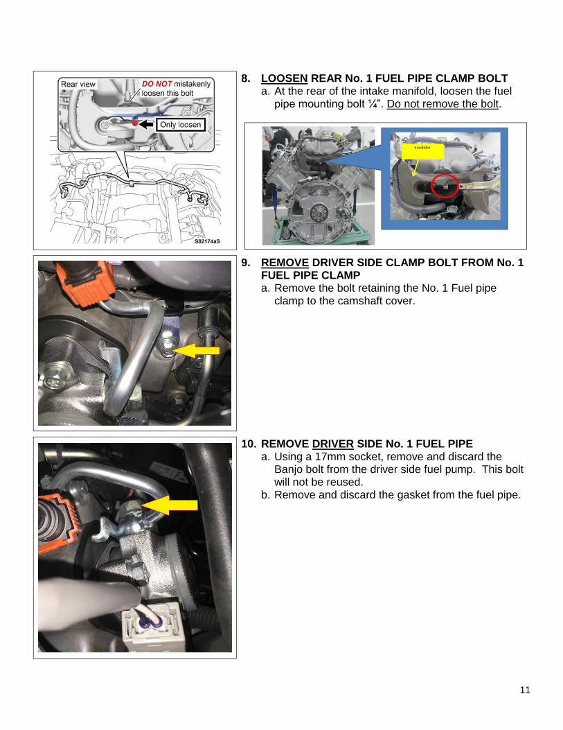
11
8. LOOSEN REAR No. 1 FUEL PIPE CLAMP BOLT a. At the rear of the intake manifold, loosen the fuel
pipe mounting bolt ¼”. Do not remove the bolt.
9. REMOVE DRIVER SIDE CLAMP BOLT FROM No. 1 FUEL PIPE CLAMP a. Remove the bolt retaining the No. 1 Fuel pipe
clamp to the camshaft cover.
10. REMOVE DRIVER SIDE No. 1 FUEL PIPE a. Using a 17mm socket, remove and discard the
Banjo bolt from the driver side fuel pump. This bolt will not be reused.
b. Remove and discard the gasket from the fuel pipe.

12
11. REMOVE PASSENGER SIDE No. 1 FUEL PIPE a. Using a 17mm socket, remove and discard the
Banjo bolt from the passenger side fuel pump. This bolt will not be reused.
b. Remove and discard the gasket from the fuel pipe.
VIII. REMOVE PASSENGER SIDE FUEL PUMP
1. ALIGN TIMING MARKS a. Using a 22mm socket on the crankshaft bolt, rotate
the engine clockwise to line up the timing mark on the balancer with the front cover.
Note: There are 3 lobes on the camshaft that drives the high-pressure fuel pump. The camshaft should be positioned so that the fuel pump lifter is located on a “flat” of the camshaft during removal and installation.
Even though the timing marks are aligned between the balancer and the front cover, it’s still possible that the engine is at TDC of the exhaust stroke and not the compression stroke. Because it’s difficult to determine actual engine position at this time, you will inspect actual camshaft position during pump removal.
2. LOOSEN BOLT FROM No. 2 FUEL PIPE CLAMP a. At the rear (bulkhead side) of the camshaft cover is
the clamp for the No. 2 Fuel Pipe. Loosen the mounting bolt for this clamp about a ¼” (6mm).

13
3. REMOVE No. 2 FUEL PIPE a. Using a 17mm Crowfoot (union nut wrench),
loosen and separate the No. 2 fuel pipe from the fuel pump.
4. REMOVE FUEL PUMP a. Gently hold the fuel pipes away from the fuel pump. b. Loosen the 2 fuel pump mounting bolts a few turns
while paying attention to the position of the pump. If the fuel pump is being lifted upward by the spring pressure of the pump, rotate the engine 120 degrees to position the camshaft on a “flat”.
c. Remove the fuel pump assembly, being careful to avoid contact with the fuel lines.
Note: Be cautious of the two O-Rings that may have stuck to the back of the lifter plate. Be sure that they do not fall into the fuel pump opening in the camshaft cover.
Hold the fuel pipes away from the fuel pump when removing to prevent damage.

14
IX. CONFIRM CAMSHAFT POSTION
1. CONFIRM CAMSHAFT POSITION
For reassembly, confirm that the lifter of the pump will be positioned on a “flat” of the camshaft, and not on a lobe.
a. Looking inside the fuel pump mounting hole, note the position of the camshaft lobe.
b. If the camshaft is not positioned on the “flat”, rotate the crankshaft the needed amount. Verify that the “flat” on the camshaft is now positioned towards the fuel pump.
X. PREPARE NEW FUEL PUMP
1. REPLACE SEALS a. Remove the original gasket and O-rings (2). b. Apply engine oil to the NEW gasket and O-Rings (2). c. Install NEW gasket and O-Rings (2).
Note: The original gasket
and O-Rings may have stuck to the fuel pump guide.
Be careful to prevent the O-Rings from dropping into the cylinder head .
d. Apply engine oil to the oil ring of the NEW fuel pump.

15
2. REMOVE LIFTER GUIDE ASSEMBLY a. While holding the fuel pump with one hand, rotate and
pull the Guide to separate it from the pump. Note: The Guide, Lifter and Insulator will be removed as an assembly. These pieces will be reused, so DO NOT discard them. b. Discard the original pump as it will not be reused.
3. ASSEMBLE NEW FUEL PUMP a. Apply engine oil to the outer surface of the lifter
and the inner surface of the guide. b. While noting the position of the lifter guide tab and
the pump’s connections, install the NEW pump into the guide.
Passenger side Driver side

16
XI. INSTALL NEW PASSENGER SIDE FUEL PUMP
1. INSTALL NEW FUEL PUMP a. Insert the pump assembly onto the engine. b. Verify the 2 alignment pins have engaged into the lifter
guide housing. c. Start the 2 mounting bolts by hand, and run them in until
they are flush against the pump housing. d. Using hand tools, alternate tightening from bolt to bolt to
evenly seat the pump assembly.
Torque: 22 ft.lbs {30 N∙m, 306 kgf∙cm}
2. CALCULATE PROPER TORQUE VALUE OF FUEL PIPE No. 2
Use the following calculation or chart to determine the setting on the torque wrench to achieve the proper torque value when using a crowfoot (union) wrench adapter.
Torque: 26 ft.lbs Calculation: Use the formula to calculate the torque wrench setting.
Chart: Pre-calculated torque adjustment for common size tools.
17
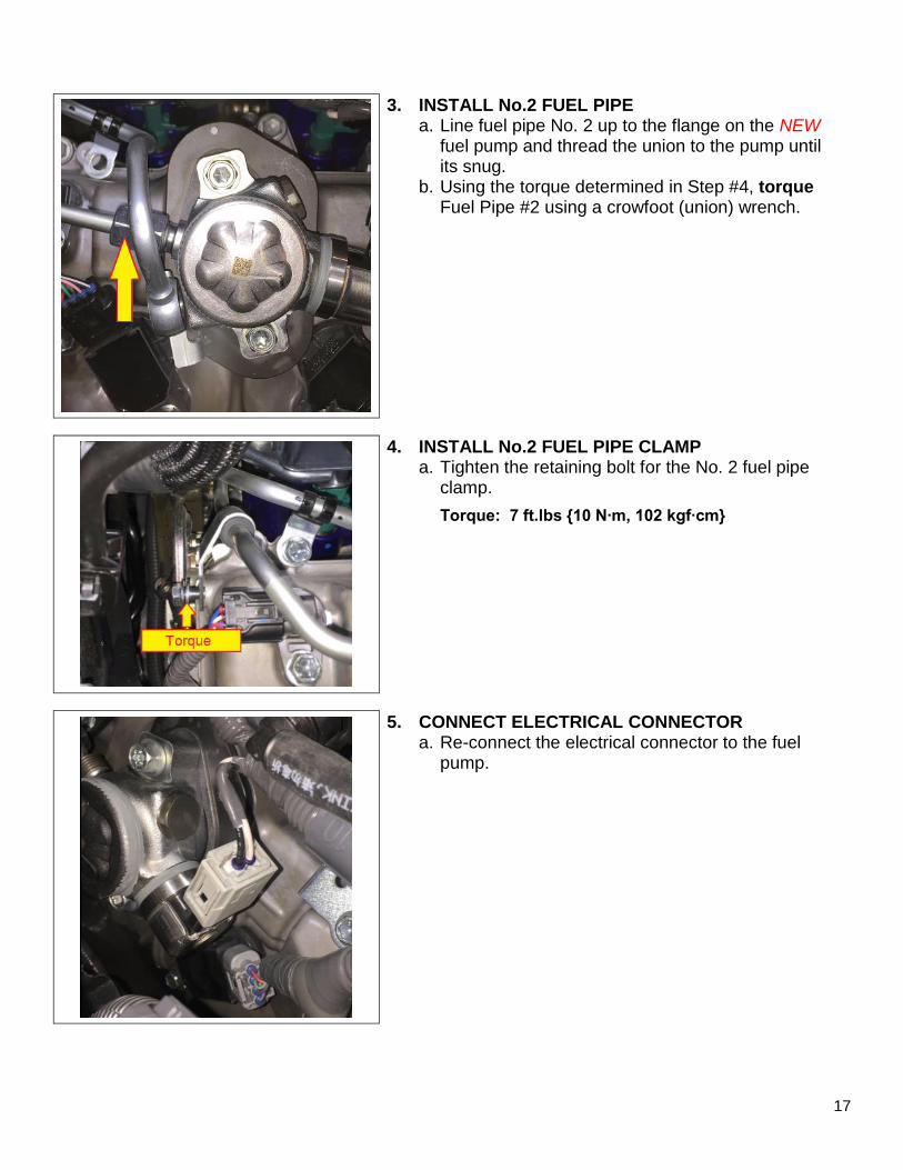
3. INSTALL No.2 FUEL PIPE a. Line fuel pipe No. 2 up to the flange on the NEW
fuel pump and thread the union to the pump until its snug.
b. Using the torque determined in Step #4, torque Fuel Pipe #2 using a crowfoot (union) wrench.
4. INSTALL No.2 FUEL PIPE CLAMP a. Tighten the retaining bolt for the No. 2 fuel pipe
clamp.
Torque: 7 ft.lbs {10 N∙m, 102 kgf∙cm}
5. CONNECT ELECTRICAL CONNECTOR a. Re-connect the electrical connector to the fuel
pump.

18
XII. REPLACE DRIVER SIDE FUEL PUMP
1. ROTATE ENGINE 120 DEGREES To properly set the camshaft on the “flat” for the driver side pump fuel, rotate the engine 120 degrees. Verify that the “flat” is positioned correctly. If not, adjust the engine position.
2. REMOVE AC BRACKET BOLT a. Remove the specified bolt that attaches the AC refrigerant
line to the shock tower. Note: This will allow the refrigerant line to move a little bit to gain more working clearance with the Drivers Side fuel pump.
3. REMOVE DRIVER SIDE FUEL PUMP
a. Following the previously detailed procedure, remove the DRIVER SIDE fuel pump from the vehicle.
Procedure: Section VIII. Remove Passenger Side Fuel Pump on page # 12 4. PREPARE NEW FUEL PUMP
a. Following the previously detailed procedure, remove the DRIVER SIDE fuel pump from the vehicle.
Procedure: Section X. Prepare New Fuel Pump # 14 5. INSTALL DRIVER SIDE FUEL PUMP
a. Following the previously detailed procedure Passenger side, install the NEW DRIVER SIDE fuel pump into the vehicle.
Procedure: Section XI. Install Passenger Side Fuel Pump on page # 16

19
6. ATTACH A/C BRACKET BOLT a. Re-install the previously removed bolt into the A/C refrigerant line bracket.
Torque: 87 in.lbs {9.8 N∙m, 100 kgf∙cm}
XIII. REASSEMBLY
1. INSTALL No. 1 FUEL PIPE – BOTH SIDES a. Install a NEW gasket on the Banjo fitting so the
bridging portion is positioned as shown. b. Using a NEW Banjo bolt, thread the fitting to the
NEW fuel pump.
Torque: 26 ft.lbs {35 N∙m, 357 kgf∙cm}
Gasket orientation:
2. INSTALL No. 1 FUEL PIPE CLAMP – BOTH SIDES a. Install the retaining bolt for the No. 1 fuel pipe
clamps.
Torque: 7 ft.lbs {10 N∙m, 102 kgf∙cm}

20
3. TIGHTEN REAR No. 1 FUEL PIPE CLAMP BOLT a. At the rear of the intake manifold, tighten the
previously loosened fuel pipe mounting bolt. Torque: 7 ft.lbs {10 N∙m, 102 kgf∙cm}
4. INSTALL BATTERY (GS-F, RC-F)
a. Install the battery and battery insulator.
b. Install the battery hold down clamp.
Torque: 26 in.lbs {2.9 N∙m, 30 kgf∙cm}
c. Attach the two positive (+) cables to the battery clamp post: Torque: 49 in.lbs {5.5 N∙m, 56 kgf∙cm}
d. Attach the negative (-) battery clamp to the post. Torque: 49 in.lbs {5.5 N∙m, 56 kgf∙cm}
5. INSTALL FENDER BRACE LH & RH (LC 500 ONLY) a. Install the 2 bolts for each brace.
Torque: 36 ft.lbs {49 N∙m, 500 kgf∙cm}
6. INSTALL SUSPENSION UPPER BRACE (RC-F ONLY) a. Install the 2 bolts and 6 nuts to install the braces.
Torque: 14 ft.lbs {19 N∙m, 194 kgf∙cm}

21
7. FINAL INSPECTIONS
a. Start the engine
b. Check for fuel leaks
c. Check for oil leaks
8. INSTALL ENGINE COVER
a. Push on the 4 corners of the engine cover to engage the clips.
9. CLEAR DTC’s
a. Using the Techstream, clear all DTC’s.
◄ VERIFY REPAIR QUALITY ►
• With the engine running, check for fuel leaks
• With the engine running, check for oil leaks
If you have any questions regarding this update, please contact your area representative.
10. APPENDIX
A. PARTS DISPOSAL As required by Federal Regulations, please make sure all recalled parts (original parts)
removed from the vehicle are disposed of in a manner in which they will not be reused, unless requested for parts recovery return.
B. CAMPAIGN DESIGNATION DECORDER
H 0 A
Year Campaign is Launched
B = 2011
C = 2012
D = 2013
E = 2014
F = 2015
G = 2016
H = 2017
Etc...
Repair Phase
1st Campaign = A
2nd
Campaign = B
3rd
Campaign = C
4th Campaign = D
5th Campaign = E
27th Campaign = 1
28th Campaign = 2
Etc...
Current Campaign Letter
for this year
0 = Remedy
1 = Interim (Remedy not yet
available) will change to
when the Remedy is available
(May use other characters in
unique cases)
Examples: C1B = Launched in 2012, Interim Phase, 2nd Campaign Launched in 2012 E0A = Launched in 2014, Remedy Phase, 1st Campaign Launched in 2014 H0A = Launched in 2017, Remedy Phase, 1st Campaign Launched in 2017.