teaching and evalution scheme displene: … sem etc... · teaching and evalution scheme displene:...
TRANSCRIPT

TEACHING AND EVALUTION SCHEME
DISPLENE: ELECTRONICS & TELECOMMUNICATION ENIGINEERING SEMESTER: IV
Subject Evolution Scheme
Theory &
Practical
Theory Practical
Sl.
No. Theory Lecturer Practical
End
Exam
Class
Test
Assignment End
Exam
Sessional Total
Marks
1. Electrical
Machine
4 - 80 15 5 - - 100
2. Analog
Electronics-II
5 - 80 15 5 - - 100
3. Analog & Digital Communication.
5 - 80 15 5 - - 100
4. Microprocessor & its Interfacing.
5 - 80 15 5 - - 100
Practical
1. Electrical
Machine Lab
4 - - - 50 25 75
2. Analog
Electronics –II
Lab
5 - - - 50 25 75
3. Analog & Digital Communication Lab.
4 - - - 50 25 75
4. Microprocessor &Interfacing Lab
4 - - - 50 25 75
5. Soft Skill & Group Discussions
- 3 25 25 50
Total 19 20 320 60 20 225 125 750

TEACHING AND EVALUTION SCHEME
DISPLENE: ELECTRONICS & TELECOMMUNICATION ENIGINEERING SEMESTER: V
Subject Evolution Scheme
Theory& Theory Practical

Practical
Sl. No.
Theory Lecturer Practical
End Exam
Class Test
Assignment End
Exam
Sessional Total Marks
1. Power Electronics & Industrial Control
5 - 80 15 5 - - 100
2. Microwaves Engineering
4 - 80 15 5 - - 100
3. Computer Networks & Mobile Technology
5 - 80 15 5 - - 100
4. Audio, Video & TV Engineering
5 - 80 15 5 - - 100
5. Advanced Microprocessor & VLSI
4 - 80 15 5 - - 100
Practical
1. Power
Electronics Lab
- 4 - - - 25 25 50
2. Microwaves
Engineering
Lab
- 3 - - - 25 25 50
3. Audio, Video & TV Engineering Lab
- 3 - - - 25 25 50
4. Advanced Microprocessor & VLSI Lab
3 - - - 25 25 50
5. Information Search ,Analysis & Presentation (ISAP)
3 - - - 25 25 50
Total 23 16 400 75 25 125 125 750
TEACHING AND EVALUTION SCHEME
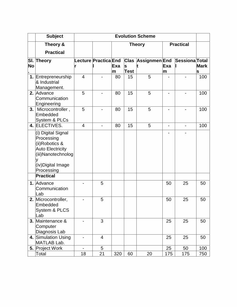
DISPLENE: ELECTRONICS & TELECOMMUNICATION ENIGINEERING SEMESTER : VI
Subject Evolution Scheme
Theory &
Practical
Theory Practical
Sl. No.
Theory Lecturer
Practical
End Exam
Class Test
Assignment
End Exam
Sessional
Total Marks
1. Entrepreneurship & Industrial Management.
4 - 80 15 5 - - 100
2. Advance Communication Engineering
5 - 80 15 5 - - 100
3. Microcontroller , Embedded System & PLCs
5 - 80 15 5 - - 100
4. ELECTIVES. 4 - 80 15 5 - - 100
(i) Digital Signal Processing (ii)Robotics & Auto Electricity (iii)Nanotechnology (iv)Digital Image Processing
- -
Practical
1. Advance Communication Lab
- 5 50 25 50
2. Microcontroller, Embedded System & PLCS Lab
- 5 50 25 50
3. Maintenance & Computer Diagnosis Lab
- 3 25 25 50
4. Simulation Using MATLAB Lab.
- 4 25 25 50
5. Project Work - 5 25 50 100 Total 18 21 320 60 20 175 175 750

IV/SEM./ETC/TH-1

ELECTRICAL MACHINE FOURTH SEMESTER
Theory : 4 P/W Examination: 3Hr Total Theory: 60 P Total Marks: 100
Theory: 80 I.A.: 15+5
A: RATIONALE: The application of Rotatory and Static Electrical machines find extensive use in modem industries is still in practice. The Electrical machine subject is intended to provide insight of different materials and in Electrical Engineering and the concept of different Electrical Machines with their operation and control. This subject also deals with the fundamental concept of single phase and three phase AC machines. B: OBJECTIVES : After Completion of the Subject students will be able to:
• Understand property & use of Electrical conducting & insulating materials. • Explain working principle & construction of DC generator. • Explain construction & working principle of motor & speed control of DC motor. • Discuss AC fundamentals. • Explain Construction & principle of transformer. • Describe principle of working of three-phase Induction motor. • Describe principle of single-phase motor.
C: TOPIC WISE DISTRIBUTION OF PERIODS.
Sl.No. Topics Periods
1 ELECTRICAL MATERIAL 04
2 DC GENERATOR 10
3 DC MOTOR 09
4 AC CIRCUITS 09
5 TRANSFORMER 08
6 INDUCTION MOTOR 12
7 SINGLE PHASE INDUCTION MOTOR 08 Total 60
D: COURSE CONTENT IN TERMS OF SPECIFIC OBJECTIVES 1. ELECTRICAL MATERIAL 1.1 Discuss properties & uses of different conducting material. 1.2Discuss properties & use of various insulating materials used electrical engineering. 1.3Explain various magnetic materials & their uses. 2.DC GENERATOR
2.1 Explain construction, Principle & application of DC Generator. 2.2 Classify DC generator including voltage equation. 2.3 Derive EMF equation & simple problems. 2.4 Define parallel operation of DC generators. 3.DC MOTOR

3.1 Explain Principle of working of a DC motor. 3.2 Explain concept of development of torque & back EMF in DC motor
including simple problems. 3.3 Derive equation relating to back EMF, Current, Speed and Torque
equation 3.4 Classified DC motors & explain characteristics, application.
3.5 State & explain three point & four point stator/static of DC motor by solid State converter. 3.6 Explain Speed of DC motor by field control and armature control method. 3.7 Explain power stages of DC motor & derive Efficiency of a DC motor. 4. AC CIRCUITS
4.1 State Mathematic representation of phasors, significant of operator “J” 4.2 Discuss Addition, Subtraction, Multiplication and Division of phasor
quantities. 4.3 Explain AC series circuits containing resistance, capacitances, Conception
of active, reactive and apparent power and Q-factor of series circuits & solve related problems.
4.4 Find the relation of AC Parallel circuits containing Resistances, Inductance and Capacitances Q-factor of parallel circuits.
5.TRANSFORMER 5.1 State construction & working principle of transformer & define conection of
Ideal ransformer. 5.2 Derive of EMF equation of transformer, voltage transformation ratio. 5.3 Discuss Flux, Current, EMF components of transformer and their phasor
diagram under no load condition. 5.4 Discuss Phasor representation of transformer flux, current EMF primary and
secondary voltages under loaded condition. 5.5 Explain types of losses in Single Phase (1-ø) Transformer. 5.6 Explain open circuit & short-circuit test (simple problems) 5.7 Explain Parallel operation of Transformer. 6.INDUCTION MOTOR 6.1 Explain construction feature, types of three-phase induction motor. 6.2 State principle of development of rotating magnetic field in the stator.
6.3 Establish relationship between synchronous speed, actual speed and slip of induction motor.
6.4 Establish relation between torque, rotor current and power factor. 6.5 Explain starting of an induction motor by using DOL and Star-Delta stator. State
industrial use of induction motor. 7.SINGLE PHASE INDUCTION MOTOR 7.1 Explain construction features and principle of operation of capacitor type and
shaded pole type of single-phase induction motor. 7.2 Explain construction & operation of AC series motor. 7.3 Concept of alternator & its application.
RECOMMENDED BOOKS:
A: TEXT BOOK:

• Fundamental of Electrical Engg. By B.L.Theraja. • Principle of Electrical Engg. By Dawes Vol. I & II. B: REFERENCE BOOK: • Electrical Technology by H.Cotton. • Electrical Machines by Dr. S.K.Bhattachary. • Principle of Electrical Machine V.K.Meheta & R.Meheta
IV/SEM./E&TC/TH-2 ANALOG ELECTRONICS – II
FOURTH SEMESTER Theory : 5 P/W Examination: 3Hr Total Theory: 75 P Total Marks: 100 Theory: 80 I.A.: 15+5 A : RATIONALE:
This subject Analog Electronics II is the continuation subject of Analog Electronics II which deals with Analog Integrated Circuits and wave shaping Circuits for various applications in Electronics Engineering. The operational Amplifier will play vital role in day to day life of most of the Electronics equipment. The concept of operational Amplifier, IC voltage regulator has also been incorporated in this subject. B: OBJECTIVES: After completing the topic, the students will able to know
• Concept of Opto Electronics. • Concept of Operational Amplifier. • Different Characteristics Op-Amp. • Concept of IC Voltage Regulator. • Idea of PCB Design.
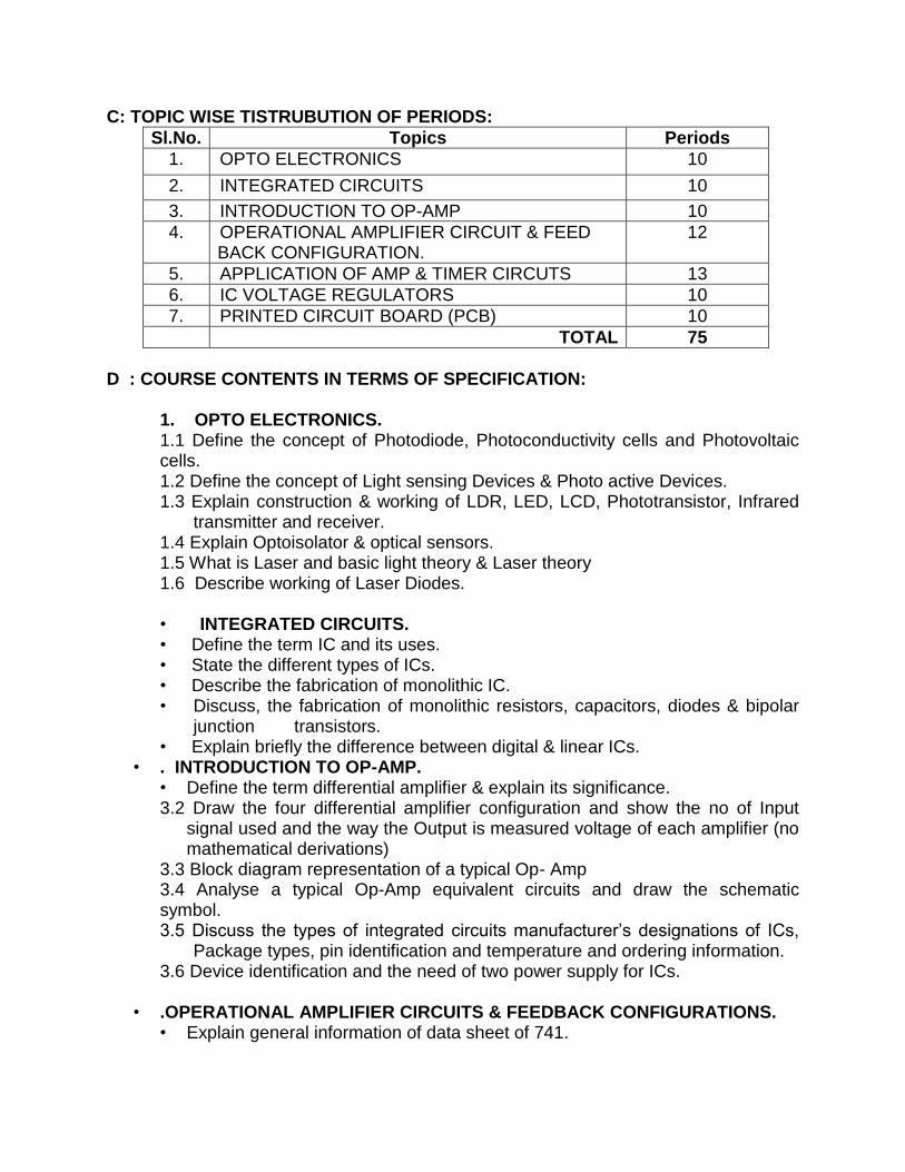
C: TOPIC WISE TISTRUBUTION OF PERIODS:
Sl.No. Topics Periods
1. OPTO ELECTRONICS 10
2. INTEGRATED CIRCUITS 10
3. INTRODUCTION TO OP-AMP 10
4. OPERATIONAL AMPLIFIER CIRCUIT & FEED BACK CONFIGURATION.
12
5. APPLICATION OF AMP & TIMER CIRCUTS 13
6. IC VOLTAGE REGULATORS 10
7. PRINTED CIRCUIT BOARD (PCB) 10 TOTAL 75
D : COURSE CONTENTS IN TERMS OF SPECIFICATION:
1. OPTO ELECTRONICS. 1.1 Define the concept of Photodiode, Photoconductivity cells and Photovoltaic cells. 1.2 Define the concept of Light sensing Devices & Photo active Devices. 1.3 Explain construction & working of LDR, LED, LCD, Phototransistor, Infrared
transmitter and receiver. 1.4 Explain Optoisolator & optical sensors. 1.5 What is Laser and basic light theory & Laser theory 1.6 Describe working of Laser Diodes. • INTEGRATED CIRCUITS. • Define the term IC and its uses. • State the different types of ICs. • Describe the fabrication of monolithic IC. • Discuss, the fabrication of monolithic resistors, capacitors, diodes & bipolar
junction transistors. • Explain briefly the difference between digital & linear ICs.
• . INTRODUCTION TO OP-AMP. • Define the term differential amplifier & explain its significance. 3.2 Draw the four differential amplifier configuration and show the no of Input
signal used and the way the Output is measured voltage of each amplifier (no mathematical derivations)
3.3 Block diagram representation of a typical Op- Amp 3.4 Analyse a typical Op-Amp equivalent circuits and draw the schematic symbol. 3.5 Discuss the types of integrated circuits manufacturer’s designations of ICs,
Package types, pin identification and temperature and ordering information. 3.6 Device identification and the need of two power supply for ICs.
• .OPERATIONAL AMPLIFIER CIRCUITS & FEEDBACK CONFIGURATIONS. • Explain general information of data sheet of 741.

• Define the following electrical characteristics input offset voltage, input offset current, CMMR, Large signal voltage gain, Slew rate .
• Define Ideal operational amplifier and its equivalent circuits. • Draw and explain the Open Loop configuration (inverting, non-inverting
Amplifier) • Draw the block representation of four feedback configurations. • Draw the circuit diagram of the voltage series feedback amplifier and derive
the close loop voltage gain, gain of feedback circuits input resistance, and output resistance, bandwidth and total output offset voltage with feedback.
• Draw the circuit diagram of the voltage shunt feedback amplifier and derive the close loop voltage gain, gain of feedback circuits, and input resistance, and output resistance, bandwidth and total output offset voltage with feedback.
5. APPLICATION OF OPERATIONAL AMPLIFIER & TIMER CIRCUITS 5.1 Discuss the summing scaling and averaging of inverting and non-inverting
amplifiers configuration. 5.2 DC & AC Amplifies using OP-AMP. 5.3 Explain the operation of instrumentation amplifier using Transducer
Bridge 5.4 Discuss the integrator and differentiator using op-amp. 5.5 Define active filter and describe the filter design of fast order low Pass
Butterworth filter. 5.6 Describe the filter design of fast order High Pass Butterworth filter. 5.7 Explain the concept of Zero-Crossing Detector using Op-Amp 5.8 Draw the block diagram and operation of IC 555 timer& IC 565 & its
application (i.e. PLL) 5.9 Explain the operation of Astable and Monostable Multivibrator & VCO
using IC555 . 5.10 Explain the working of Wein Bridge Oscillator using operational Amplifier. 5.11 Explain the Voltage to Current Convertor using Operational Amplifier. 5.12 Explain the Voltage to Current Conversion using Operational Amplifier.
6. IC VOLTAGE REGULATORS 6.1 Explain the operation of power supply using 78XX and 79XX Series (Fixed Voltage Regulator)
6.2 Draw the functional block diagram of IC regulator LM 723 &LM 317. 6.3 Explain the voltage power supply using LM 317 and LM 337. 6.4 Explain the voltage power supply using LM 723.
• PRINTED CIRCUIT BOARD (PCB). • Discuss the different types of PCB : single sided double sided multi layer • Explain the PCB design principle (Brief description): The schematic Diagram,
Layout design, Artwork, Manufacturing of film master. • Explain PCB fabrication procedure (Brief description): Cutting of PCB,
Cleaning, Lamination, Exposing, Developing, Etching, Drilling, Solder Max, Tinning, Legend Printing and Finishing.

Recomonneded Books: A: TEXT BOOK: • Operational Amplifier & Linear Integrated Circuit – R.K. Geakward (PHI) • PCB Design Technology Walter Boshart. B: REFERENCE BOOK: • Electronics & Devices & Circuits by Jacob Milliman, C.Halkias & S.Jit. • Liner Electronics Circuits & Devices-James cox. • L.M. on PCB Fabrication by NTTF –Bangalore. • Linear Integrated circuits by J.B.Gupta(Katson)
IV/SEM./ETC/TH-3 ANALOG & DIGITAL COMMUNICATION
FOURTH SEMESTER Theory : 5 P/W Examination: 3Hr Total Theory: 75 P Total Marks: 100 Theory: 80 I.A.: 15+5 A: RATIONALE:

The subject Analog & Digital Communication deals with different types of Electronics Communication System includes basic process, Principle & methods of different Analog & Diital Communication System including Transmitters & Receiver. Different modulation techniques have been discussed in this subject. B: OBJECTIVES; On completing the topic, the students will able to know
• Need of modulation and classify modulation. • Discuss modulation & balanced modulators,& Methods of generating SSB
signal & Vestigial side band signal. • Principle of Frequency Division Multiplexing. • Principle of AM & FM demodulators & AM & FM Radio transmitter & receiver
using block diagram. • Frequency modulation & expression for frequency-modulated signal. • Discuss the generation and detection of PAM, PWM & PPM system. • Explain quantization of signal & quantization error • Explain generation & demodulation of PCM system & T carrier system. • Explain the operation of Time Division Multiplexing • Explain the generation & demodulation of Delta modulation & Adoptive Delta
modulation. • Discuss the generation and detection of binary ASK, FSK,PSK ,QPSK, QAM,
MSK. • Explain the operation of Spread Spectrum Modulation Techniques. • Define the channel capacity formula C : TOPIC WISE DISTRIBUTION OF PERIODS.
Sl.No. Topics Periods
1. Elements of communication systems 06
2. Analog Communication Systems 18
3. AM & FM receiver 15
4. AD Conversion & Pulse Modulation 16
5. Digital Communication 20 Total 75
D : COURSE CONTENTS IN TERMS OF SPECIFIC OBJECTIVES: • Elements of communication systems.
• Define Elements of Communi9cation System • Define source of information. • Define Communication Channels. • What are the Classification of Communication systems? • Define analog and digital Signals. • Define transformation Power and Chanel band width.

2. ANALOG COMMUNICATION. 2.1 Amplitude Modulation System 2.1.1 Explain need of modulation and classify modulation. 2.1.2 State & explain Amplitude modulation derive the expression for
amplitude modulation signal, power relation in AM wave & find Modulation Index.
2.1.3 State and explain AM demodulators (liner diode detector, square law detector & PLL)
2.1.4 State & explain SSB signal and DSBSC signal • State methods of generating & detection SSB signal (Indirect
method & phasing method.) • State the methods of generation DSB-SC signal (Ring modulator )
and detection of DSB-SC signal (Synchronous detection) • Discuss modulation & balanced modulators • Discuss the concept of Multiplexing & Explain operation of
Frequency Division Multiplexing. •
2.2 Frequency Modulation Systems. 2.2.1 State and explain frequency modulation and basic Principle. 2.2.2 Derive the expression for frequency-modulated Signal & find Modulation Index and sideband 2.2.3 Explain the frequency spectrum of FM signal. 2.2.4 State and explain phase modulation 2.2.5 Compare between AM and FM modulation. • Discuss the methods of FM generation.(Parameter variation method,
Armstrong method.) 2.2.7 Explain the principle of operation of FM demodulator.(Forster Seely Discriminator)
Explain the working principle of FM stereophonic FM transmitter.
3. AM & FM RECEIVER 3.1 State the working of super heterodyne radio receiver with block diagram. 3.2 State the working of FM Receiver with Block Diagram.
3.3 Explain the working of stereo phonics FM receiver. 3.4 State and explain the terms Selectivity, Sensitivity, Fidelity and Noise Figure . 3.5 Explain R.F amplifier mixer using transistor and I.F amplifier. 3.6 State and explain image signal selection of I.F and alignment of receiver.
4. ANALOG TO DIGITAL CONVERSION & PULSE MODULATION SYSTEM.
4.1State and explain Sampling Theorem & Nyquist rate & Aliasing& classify Sampling, 4.2 Discuss the generation and detection of PAM, PWM & PPM system. 4.3 Explain quantaization of signal & quantization error. 4.4 Explain generation & demodulation of PCM system. 4.5 Explain the working of T-Carrier system.

4.6 Define Time Division Multiplexing & explain the operation of Time Division Multiplexing.
4.7 Explain the generation & demodulation of Delta modulation. 4.8 Explain the generation & demodulation of Adaptive Delta Modulation.
5. DIGITAL COMMUNICATION.
5.1 State & explain Digital Communication. 5.2 State the advantages of digital communication system. 5.3 Classify digital modulation techniques. 5.4 Discuss the Generation and Detection of binary ASK, FSK, PSK, DPSK
,QPSK, QAM, MSK,GMSK. 5.5 Explain the operation of Spread Spectrum Modulation Techniques (DS-SS & FH-SS). 5.6 Define the channel capacity formula.(Shannon Theorems) 5.7 List of Application of Different Modulation Schemes. 5.8 What are types of Modem & its Application?
RECOMMENDED BOOKS: • Text Books:
• Electronic Communication by G.Kennedy. • Electronics Communication by Sanjay Sharma. • Principle of Communication by A.Singh & A.K.Chabra.
• Reference Books:
• Principle of Communication by Lovis E.frenzel. • Radio Engineering by G.K Mithal. • Communication System by R.P.Singh & S.D.SAPRE. • Advanced Communication by Thomasi. • Digital Communication by CH Kranthi Rekha

IV/SEM./ETC/TH-4 MICROPROCESSOR & ITS INTERFACING
FOURTH SEMESTER Theory & Tutorial-5P/W Examination: 3Hr Total Theory & Tutorial: 75 P Total Marks: 100 Theory: 80 I.A: 15+5 A: RATIONALE:
The Microprocessor control has taken predominance over other types of control quite some time past. Starting from Electrical Power plant to consumer electronics this tiny chip finds extensive uses. As such Microprocessors have made pervading influence on our lives. This field is developing so rapid that it is difficult to keep track with the changes. Under this subjects Architecture and instruction sets of 8 bit and 16 bit processor have been discussed. Some applications have been included through the interfacing chips. B: OBJECTIVS: On completion of the subject, the student will be able to:
• The students will able to differential between 8085 microprocessor. • Classify Bus. • Describe the Architecture of 8085 microprocessor. • Comprehend different instructions of 8085 microprocessor. • State & explain addressing modes. • Write instructions under different addressing modes. • Discuss assembler. • Explain basic assembler directives. • Describe types of assembly language programs and write programs. • Explain the timing diagrams of different instructions. • State the functions of the interfacing chips like 8255, etc. • Explain the delay subroutine. • Calculate the delay in ms by one, two or three registers. • Explain ADC & DAC? • Explain the use of ADC & DAC modules • Write a program for traffic light control. • Apply Programming technique for stepper motor control.
C: TOPIC WISE DISTRIBUTION OF PERIODS:
Sl.No. Topics Periods
1. INTRODUCTION TO MICROPROCESSOR 05
2. BASIC ARCHITECTURE OF8-BIT MICROPROCESSOR. 10
3. INSTRUCTION SETS 10
4. PROGRAMMING TECHNICS 10
5. TIMING DIAGRAMS 08

6. INTERFACING I/O & MEMORY 10
7. INTERFACING I/O PROGRAMMING 08
8. 16BIT MICROPROCESSOR 14 TOTAL 75
D: COURSE CONTENTS IN TERM OF SPECIFIC OBJECTIVES:
• INTRODUCTION MICROPROCESSOR • Discuss Microprocessor & its Application. • Distinguish between microprocessor & microcomputer. • Discuss Evolution of microprocessor.
• BASIC ARCHITECTURE OF 8-BIT MICROPROCESSOR. • Discuss Architecture. • State & Explain BUS. • Study general Bus structure. • Describe address bus, data bus, control bus & System Bus. • Describe pin structure of 8085 Microprocessor. • Describe internal Architecture of 8085 Microprocessor with a Block
Diagram. • Describe three state registers & its application in multiplexing of
buses. • Study the data transfer using tri-state registers & Concept of
Multiplexing. • Discuss application of Arithmetic logic unit & Program Counter. • State & explain stack pointer, stack & stack top. • Define registers of 8085. • Distinguish between SPR & GPR. • Describe 8085 interrupt & interrupt Acknowledge Signal.
• INSTRUCTION SETS. 3.1 Explain need for addressing data. 3.2 Differentiate between 1-adress, 2-adress & 3-adress instructions with examples. 3.3 Define addressing modes with suitable examples. 3.4 Explain different types of Instructions.(Data Transfer, Arithmetic,
Logical, Branching, Stack& I/O Machine Control) 3.5 Simple Programs of 8085 Instructions. 3.6 Explain the basic assembler directives.
4. PROGRAMMING TECHNICS Write the program based on
• Logic Operations (AND,OR,Complement1’s&2’s) & Masking of bits. • Counters & Time delay (Single Register, Register Pair, More than Two Register)
4.3 Looping, Counting & Indexing (Call/JMP etc). 4.4 Stack & Subroutines. 4.5 Code conversion, BCD Arithmetic & 16Bit data Operation, Block Transfer. 4.6 Array Handling (Largest number & smallest number in the array)

5.TIMING DIAGRAMS. 5.1 Define T-State, Fetch cycle, Machine Cycle, Instruction cycle & discuss the
concept of timing diagram. 5.2 Differentiate between instruction cycle, machine cycle & T-state. 5.3 Draw op-code phase machine cycle (4 & 6 T-state) timing diagram. 5.4 Draw timing diagram for memory read, memory write, I/O read, I/O write machine cycle. 5.5 Draw a neat sketch for the timing diagram for 8085 instruction (MOV, DCR,
MVI, LDA, DCX). • INTERFACING I/O & MEMORY PROGRAMMING
• Discuss interfacing. • Describe the pin diagram of 8255 chip and explain function of each pin. • Describe internal architecture of 8255. (PPI) • Define Mapping & Distinguish between Memory mapping & I/O Mapping. • Explain Memory interfacing with RAM & EPROM to Microprocessor • Explain Functional Block Diagram 8257 DMA controller. • Explain Functional Block Diagram 8259 Programming Interrupt Controller. • Explain the functional Block Diagram 8251(USART)
• INTERFACING I/O PROGRAMMING. • Describe ADC & DAC with Interfacing. • Interface a traffic light control system using 8255. • Write interfacing programme for stepper motor control.
8. 8086 MICROPROCESSOR AND INSTRUCTION SET 8.1 Explain the block diagram of a Microprocessor based system. 8.2 Explain the internal architecture of 8086-Programming model. 8.3 Explain pin details of 8086 / 8088. 8.4 To calculate the physical address of a memory location. 8.5 Explain flag register. 8.6 Explain the basic 8086 system timing diagram. 8.7 Explain the Instruction format-Memory addressing machine. 8.8 Explain minimum and maximum mode of 8086 operation. 8.9 Explain addressing modes of 8086. 8.10Explain interrupts and vector table. 8.11 Compare 8086 & 8088. 8.12 Explain basic features of 8087 coprocessor. 8.13 Explain the various assembler directives of 8086. 8.14 Discuss instruction set-Data transfer-Arithmetic and logical, Branching-
loop control.& String control instruction
RECOMMENDED BOOKS: • TEXT BOOKS:
• Microprocessor Arch, Programming & Application by R.S. Goankar. • Advanced microprocessor and peripherials, programmer by A.K.Roy and
K.M.Bhurchand, PHI. • Microprocessor & micro computer By S.K. Mandal ,TMH

• REFERENCE BOOK: • Microprocessor & its application by B.Ram. • Microprocessor by M. Rafiquizaman,PHI • Microprocessor & Pherials- S.P. Chowdhury & Sunetr Choudhury • Understanding 8085/8086 By S.K. Sen ,New Age Int. Publication
IV/SEM./ETC/PR-1 ELECTRICAL MACHINE LAB
FOURTH SEMESTER Period / Week: 4 End Exam.: 25 Total Contact hrs:60 Sessional: 25 Exam. Time: 4 Hours A: RATIONALE: This Lab gives understanding of different Electrical Machine i.e. DC Generator, DC Motor, Transformer, etc. The students will able to identify different parts and connections and test the equipment. B: OBJECTIVS: On completing of this Lab. Course the students will able to
• Run the DC Generator & DC Motor. • Connection of above Machine. • Find the losses of Transformer & different Students.
C: COURSE CONTENT OF SPECIFIC OBJECTIVE: • Study different parts of DC Generator. • Run a DC shunt Generator and • Connect and run DC Motor (series, shunt and compound motor with suitable
stators connections & measure speed.). • Study 3 point & 4 point starter. • Study speed Control of DC shunt motor(field and armature voltage method) • Parallel operation of DC generator. • Connect & run a 3- I.M. with the help of star-delta stator. • Identify the terminals of a transformer connect short circuit & open circuit test &
find the losses.. • Determine voltage regulation of transformer by direct loading. • Construct switch board using cut-out, switches, plugs, holder and two ways
Switch. • Study Parallel operation of Transformer.

IV/SEM./ETC/PR-2 ANALOG ELECTRONICS LAB – II
FOURTH SEMESTER Period / Week: 5 P/W End Exam.: 50 Total Contact hrs:75 P Sessional: 25 Exam. Time: 4 Hours A: RATIONALE: This Lab. Based on the application of Operational Amplifier & IC Voltage Regulated & PCB Design. The students will used software & Circuit maker software at the end of the section. B: OBJECTIVS: After Completing the Lab. The student will able to know
• The Characteristics of operational Amplifier. • Construction of Timer Circuit. • Construction of Power Supply IC based. • Idea of PCB Design.
C: COURSE CONTENT OF SPECIFIC OBJECTIVE: 1. Construct and test voltage power supply using 78xx &79xx ICs 2. Construct and test voltage power supply using CM723. 3. Study of Operational Amplifier 741 & Timer IC 555. 4. Determine the following characteristics of an OP-Amp. i) Input off-set voltage. ii) Slew rate. iii) CMMR

iv) Bandwidth. v) Input bias current. 5. Construct and study inverting and non-inverting OPAMP. 6. Construct and study integrator and differentiator using OPAMP. 7. Construct and study voltage comparator using OPAMP. 8. Construct and study performance of Instrumentation Amplifier. 9. Construct and study timer using IC 555 (Astable & Monostable) 10. Construct and study IC 565 PLL and find range & capture range.. 11. PCB Design (Do Sl 5 to 10 using Pspice Software) Mini project: After PCB design place the component and test the Electronics Circuit and prepare a report at the end of session. At the end of Semester.Drafting, Simulation & design of PCB can be carried out using the following suitable software.
a) DC Regulator Power Supply 2A, 0-30V. b) Clock Display (Hr.Min.Sec.) Format. c) Frequency Counter d) Counter & Display upto 999.
* SOFTWARE 1. B2-Spice + Eagle : Simulation & PCB design software. 2. Supper CAD. 3. Electronics work bench: Simulation. 4. CADSTAR : PCB Design. 5.P Spice : Simulation 6. Edwin : Simulation + PCB design. 7. ORCAD 8. Circuit Maker & etc. REFERENCE BOOKS: 1. Handbook of PCB Design – G.Ceorida
IV/SEM./ETC/PR-3 ANALOG & DIGITAL COMMUNICATION LAB.
FOURTH SEMESTER Period / Week: 4 P/W End Exam.: 50 Total Contact hrs:60P Sessional: 25
Exam. Time: 4 Hours A: RATIONALE: This Laboratory Is the based on Communication System based on Analog & Digital Communication The students will able to test and observe various communication equipment including Transmitter & Receiver. B: OBJECTIVE: After Completing the Lab. Course the students will able to know
• Concept of AM transmitter & Receiver. • Concept of FM Transmitter & Receiver. • Concept of Digital (PCM/ASK/FSK/PSK)
C: COURSE CONTENTS IN TERM OF SPECIFIC OBJECTIVES:
1. Study of AM transmitter & Detector and observe the waveform at different test point.

2. Determine percentage of Modulation Index of AM. 3. Study of FM transmitter & Detector & observe the waveform at Different section. 4. Study of SSB signal & observe the waveform at different section. 5. Study of sampling theorem & observe the waveform at different section. 6. Study of PCM transmitter & receiver & observe the waveform at Different section. 7. Study of ASK modulator & demodulator & observe the waveform at different
section. 8. Study of FSK modulator & demodulator & observe the waveform at different
section. 9. Study of PSK modulator & demodulator & observe the waveform at different
section. 10. Study of delta modulator & demodulator& observe the waveform at different
section. 11. Mini project: The students will collect the detail specification
and Catalog of all equipments used and submit at end of session. Perform a transmitter & receiver using array modulation system.
IV/SEM./ETC/PR-4 MICROPROCESSOR & ITS INTERFACING Lab
FOURTH SEMESTER
Period / Week: 4 P/W End Exam.: 25 Total Contact hrs:60 P Sessional: 25
Exam. Time: 4 Hours A: RATIONALE:
The Microprocessor control has taken predominance over other types of control quite some time past. Starting from Electrical Power plant to consumer electronics this tiny chip finds extensive uses. As such Microprocessors have made pervading influence on our lives. This field is developing so rapid that it is difficult to keep track with the changes. Under this subjects Architecture and

instruction sets of 8 bit and 16 bit processor have been discussed. Some applications have been included through the interfacing chips.
B: OBJECTIVE: After Completing the Lab. Course the students will able to know
• The concept of Microprocessor 8085 (8Bit) • Concept of 16 Bit Processor 8086 • Programming & Interfacing Concept
C: COURSE CONTENTS IN TERM OF SPECIFIC OBJECTIVES:. • Discuss microprocessor trainer kit. • Draw the pin & internal Architecture structure of 8085. • Write a program for 8-bit addition & subtraction. • Write a program for multi byte addition. • Write a program for multiplication & division of two 8-bit numbers. • Write a program to find the maximum value in an array. • Write a program for arranging the given data in ascending & descending order. • Write a program for BCD to Hex & ASCII to Binary & Vice Versa conversion. • Write a program to find the square root of a given data. • Write a program for generating Deley using one resister, Two register & three
register. • Write a program for Up counter & Down counter with one second delay. • Write a program for interfacing using 8085.
• Glowing of light (Moving) using 8255. • Display your name (4bit using 8279) • Traffic light controller • Steeper Motor Controller • DC Motor Control • 8-Bit ADC & DAC
• Write the simple program using 8086 Microprocessor (Addition, Subtraction, Division, Multiplication, String Manipulation)
IV/SEM./ETC/PR-5 SOFT SKILLS& Group Discussions
FOURTH SEMESTER Period / Week: 3 P/W End Exam.: 25 Total Contact hrs:45 P Sessional: 25
Exam. Time: 4 Hours

A: RATIONALE: The Soft Skill will provide Motivation among the students to develop new Technology Based on Advances in Electronics & Provide Guidance for Carrier Growth. The student will enhance their skills through Group Discussion & Presentation. They are communication skills with Managerial capability will be enhanced. B: OBJECTIVE: After Completing the Lab. Course the students will able: To motivation the students in developing life skills for successful career growth. C: COURSE CONTENTS IN TERM OF SPECIFIC OBJECTIVES: A: Split of Course Content 1. Lecturer 15 hrs On relevant new technologies(i.e. internet) On soft skills 2. Group Discussions 15 hrs 3. Presentations(OHP/PPT) & Industrial Visit 15 hrs Total 45 hrs Guidelines: B 1. All the above activities shall be students centred. 2. All the students shall be divided in to batches of 5 students or less.
3. Students are divided into batches for the purpose of ensuring guidance and assessment 0nly
4. All the batches shall be divided and entrusted to among the available Students.
5. Internal faculty shall act as guides & facilitators 6. Internal assessment shall be the responsibility of the faculty members to whom the students are entrusted. 7. The faculty members shall provide all the guidance needed for the
students motivate them and ensure their active participation in all above activities.
8. Lecturers shall be arranged by the students with active support of the faculty.
9. Each batch of the students shall arrange at least one lecture, One Group Discussion and One Presentation.
10. At least 75% of the lectures shall be from external experts. 11. All the students of the class shall be present during all the activities,
though the initiative could be from any one of the batches. 12. For each of the activities, a single session of two hours, there can be 1 or
more lecturers or group discussions or presentation, ensuring the beneficial limits. The student are utilise the English Communication laboratory for Lectures and Group Discussion
13. Each students shall prepare a report independently on each of the lecture / Group Discussion sessions or presentation, ensuring the beneficial limits.
14. All the presentations by the students shall be computer aided using Power Point.
15. Each of the students shall submit a copy of the presentations made by him/her to his/her guide.
16. Every students shall maintain a file of the valued reports on lecture and group discussions along with copies of the presentations made by his group. Their day today activities will be recorded as annexure.
17. During group discussions and presentations, involvement of every student in the batch shall be ensured, by allocating a part of the group discussion and presentation to each of the students in the batch.
18. External experts shall be involved during group discussions & Presentations also to the extent possible.
19. When any of these sessions are in progress all the faculty members shall be present unless there is clash of theory & practical of other semesters for them. For this purpose, if need be the tables may be re-arranged.
20. However the guide for the batch of students who have taken the initiative of any or the activates shall be present during the session with out fail.
21. The guide for the each batch each of the batches shall observe his students with respect to all the parameters identified for marking marks for each of his students.
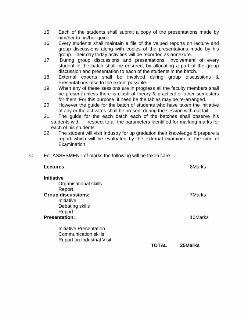
22. The student will visit Industry for up gradation their knowledge & prepare a report which will be evaluated by the external examiner at the time of Examination.
C For ASSESMENT of marks the following will be taken care Lectures: 8Marks Initiative Organisational skills Report Group discussions: 7Marks Initiative Debating skills Report Presentation: 10Marks Initiative Presentation Communication skills Report on Industrial Visit
TOTAL 25Marks