tcs using micom relays
TRANSCRIPT

APPLICATION GUIDE AG019C
2012 Page 1 of 26 15 June 2012
Signed: ............................................................. Author: Tony Hassall
Sales Support Engineer Date: 15 June 2012
Signed: .............................................................. Approved By: John Wright
Engineering Manager – Automation Support Date: 15 June 2012
T&D
Automation & Information Systems – St Leonards Avenue – Stafford – ST17 4LX – England Tel : +44(0)1785 223251 - Fax : +44(0)1785 212232
ALSTOM T&D UK LTD. Registered Of f ice : St Leonards Avenue – Staf ford – ST17 4LX Registered in England : 4955841
Trip Circuit Supervision
Using MiCOM Relays
Px2x, Px3x and Px4x
(n.b. Please also refer to AG014 which contains up-to-date Px4x TCS information, and to
P14N/P14D/P94V manuals which provide up-to-date “AGILE” TCS information)


Trip Circuit Supervision Using Micom Relays
Px2x, Px3x and Px4x
AG019C
TABLE OF CONTENTS
1 INTRODUCTION ............................................................................................................ 4
2 REFERENCES ............................................................................................................... 4
3 HISTORICAL IMPLIMENTATION & SIMULATION ON MICOM RELAYS ...................................... 5
3.1 SCHEME H4 – MVAX21 ..................................................................................................... 5
3.2 SCHEME H7 - MVAX31 ..................................................................................................... 6
4 PROPOSED TRIP CIRCUIT SUPERVISION ........................................................................... 8
4.1 SCHEME SUITABLE FOR FLEETING (SELF-RESET) TRIP CONTACTS ................................................. 8
4.1.1 Scheme Philosophy for Fleeting Trip Contacts ............................................................... 8
4.2 SCHEME SUITABLE FOR NON-FLEETING (LATCHED OR PULSED) TRIP CONTACTS .............................. 9
4.2.1 Scheme Philosophy for non-fleeting trip contacts .......................................................... 9
5 HARDWARE & SOFTWARE VERSIONS OF THE MICOM PX2X, PX3X & PX4X IEDS ................... 11
6 TCS DESIGN CONSIDERATION & RESISTOR CALCULATIONS IN PX2X RELAYS ........................ 12
6.1 IMPLEMENTATION ............................................................................................................ 12
6.2 RELAY OPTO DETAILS ....................................................................................................... 12
6.3 THEORETICAL RESISTANCE CALCULATIONS ............................................................................. 12
6.4 CONFIGURATION & SETTING LOGIC’S (S&R) FOR NON-FLEETING TRIP CONTACTS ........................... 13
7 TCS DESIGN CONSIDERATION & RESISTOR CALCULATIONS IN PX3X RELAYS ........................ 19
7.1 IMPLEMENTATION ............................................................................................................ 19
7.2 RELAY OPTO DETAILS ....................................................................................................... 19
7.3 THEORETICAL RESISTANCE CALCULATIONS ............................................................................. 19
7.4 CONFIGURATION & SETTING LOGIC’S (S&R) FOR FLEETING/NON-FLEETING TRIP CONTACTS .............. 21
8 TCS DESIGN CONSIDERATION & RESISTOR CALCULATIONS IN PX4X RELAYS ........................ 22
8.1 IMPLEMENTATION ............................................................................................................ 22
8.2 RELAY OPTO DETAILS ....................................................................................................... 22
8.3 RESISTANCE CALCULATIONS ............................................................................................... 22
8.4 PROGRAMMABLE SCHEME LOGIC FOR FLEETING TRIP CONTACTS ................................................. 23
8.4.1 Figure 5 shows the PSL proposed for TCS when using fleeting (self-reset) contacts. ...... 23
8.4.2 Programmable Scheme Logic for non-fleeting trip contacts .......................................... 23
9 CONCLUSIONS AND RECOMMENDATIONS ....................................................................... 25

AG019C
Trip Circuit Supervision Using Micom Relays
Px2x, Px3x and Px4x
Page 4 of 26 15 June 2012
1 INTRODUCTION
The trip circuit, in most protective schemes, extends beyond the relay enclosure and passes
through components such as fuses, links, relay contacts, auxiliary switches and other terminal
boards. This complex arrangement, coupled with the importance of the trip circuit, has led to
dedicated schemes for its supervision.
It is desirable to provide supervision of the trip path and coil with the CB either closed or open.
Additionally, no single component failure (to short circuit) should cause a trip and the scheme
should work correctly regardless of the trip signal type (latched or self-reset). Its operation is
historically simply a product of the two supervision coils being connected in series with an
additional alarm coil for power supply supervision.
The schemes presented in this document apply to MiCOM Px2x, Px3x & Px4x IEDs with versions
detailed under section 5.0 and that have the universal, opto-isolated inputs.
This report details the tests performed with different Breaker design and the results are recorded
on the proposed trip circuit supervision circuit arrangement compliant to H7 requirement using
the Micom Relays opto-isolator input facility.
2 REFERENCES
Reference Doc. Number Doc. Name
A P438/EN M/A41 Technical Manual for P438
B Mvax12-91_en_0902 MVAX 12, 21, 31, 91 Trip Circuit
Supervision Relays
C ER-S15 ENA Engineering Recommendation S15
(schemes H4 to H7)
D P14x/EN AP/B54 Application Notes
E 140/MICOM_TRIP_Supervision Verification Tests on Proposed Trip
Circuit Supervision scheme using the
opto-input circuit on MiCOM Px40
F STS000065, Rev.02 Wiring Diagram NR CBR single pole
version
G 150/PP0124 Verification Tests :
H7 Trip Circuit Supervision scheme
using Fast Hybrid Trips and Px30 Opto
Input circuit.
H Engineering Report Engineering Report TCS_P438_CBR
Breaker application_Project Currie
Issue B

Trip Circuit Supervision Using Micom Relays
Px2x, Px3x and Px4x
AG019C
Page 5 of 26 15 June 2012
3 HISTORICAL IMPLIMENTATION & SIMULATION ON MICOM RELAYS
The existing schemes currently provided by electro- mechanical relays in the ALSTOM range are based
upon the requirements of Engineering Recommendation S15 (schemes H4 to H7) produced in the UK
by the Electricity Association (and now available from ENA). Additional requirements are also added
from National Grid in NGTS 3.6.13.
This section will look to describe each of the four schemes in some detail highlighting what is and isn't
supervised and which relay(s) can be utilised from the current product portfolio.
3.1 Scheme H4 – MVAX21
The H4 scheme in its simplest form places a relay coil (or lamp) in parallel with the trip contact(s) and
in series with the circuit breaker normally open contact (52a) and trip coil. This simple circuit ensures
that with the CB closed a relatively small current passes through the trip circuit and checks its
continuity. In the event of either an open circuit trip circuit, trip coil or 52a contact the relay coil will
simply reset and it associated contacts will be available for local and/or remote indication.
The engineering recommendation (ER S15) also stipulates a number of additional requirements to
enhance the functionality of the scheme:
� An accidental short circuit of any single element in the supervision relay should not permit
tripping of the CB with the supervision current not exceeding 60mA
� The supervision current under normal operation must not exceed 20mA between 80% and 120%
of nominal working voltage.
� Supervision alarm contacts must not operate in less than 400ms
Based upon these additional factors, it is necessary to ensure that a resistor is fitted in series with the
supervision coil and its ohmic value must be closely monitored to ensure that the supervision current
requirements are met.
The MVAX21 provides supervision in accordance with scheme H4 and the circuit diagram is shown in
figure 1.
Figure 1: Scheme H4 – MVAX21
AG019C
Trip Circuit Supervision Using Micom Relays
Px2x, Px3x and Px4x
Page 6 of 26 15 June 2012
In figure 1 we note that the MVAX21 actually utilises two coils; one connected in the supervision
circuit (RL2) and the other providing the alarm contacts (RL2). This is necessary to ensure that
spurious alarms are not given when the CB is open since the second coil from which the alarm
contacts are taken may be energised when the CB is open using a CB 52b contact.
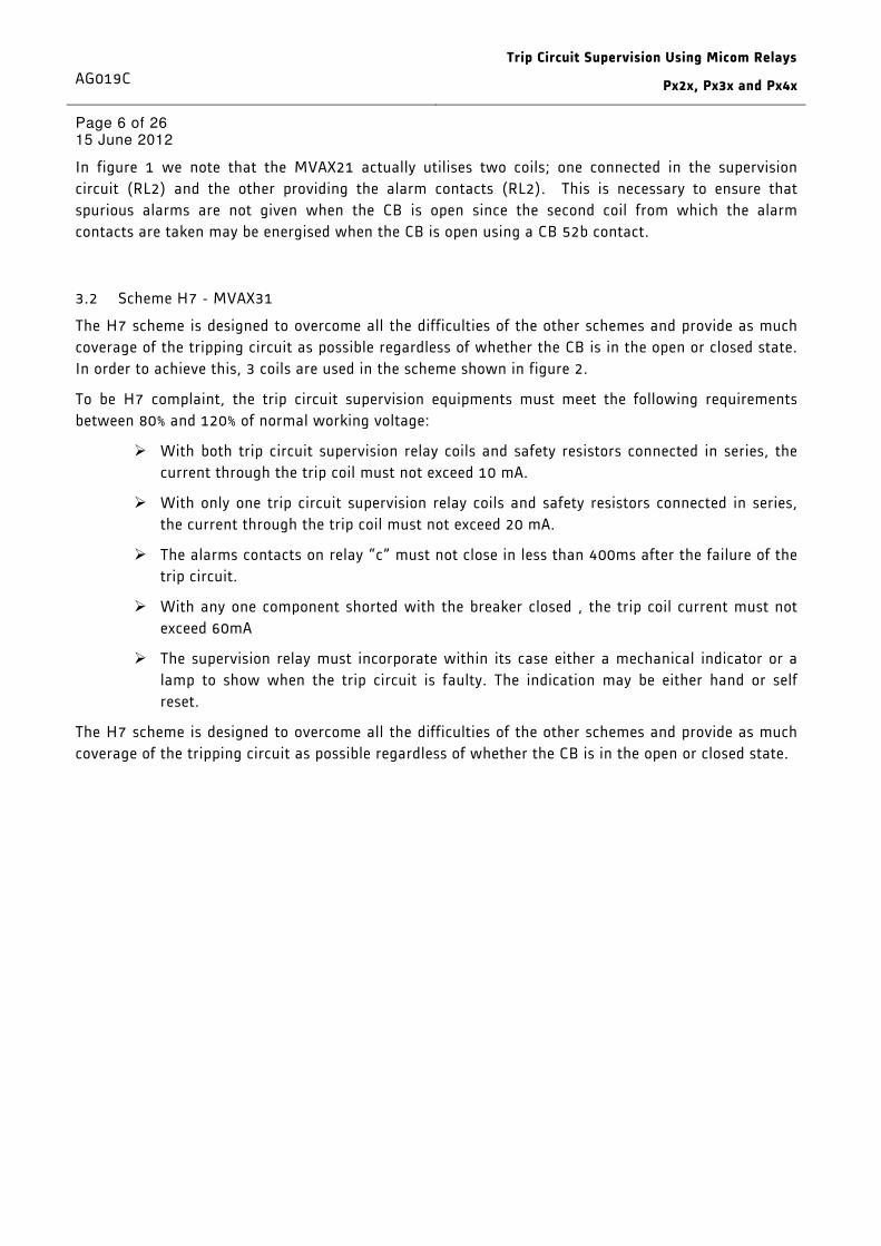
3.2 Scheme H7 - MVAX31
The H7 scheme is designed to overcome all the difficulties of the other schemes and provide as much
coverage of the tripping circuit as possible regardless of whether the CB is in the open or closed state.
In order to achieve this, 3 coils are used in the scheme shown in figure 2.
To be H7 complaint, the trip circuit supervision equipments must meet the following requirements
between 80% and 120% of normal working voltage:
� With both trip circuit supervision relay coils and safety resistors connected in series, the
current through the trip coil must not exceed 10 mA.
� With only one trip circuit supervision relay coils and safety resistors connected in series,
the current through the trip coil must not exceed 20 mA.
� The alarms contacts on relay “c” must not close in less than 400ms after the failure of the
trip circuit.
� With any one component shorted with the breaker closed , the trip coil current must not
exceed 60mA
� The supervision relay must incorporate within its case either a mechanical indicator or a
lamp to show when the trip circuit is faulty. The indication may be either hand or self
reset.
The H7 scheme is designed to overcome all the difficulties of the other schemes and provide as much
coverage of the tripping circuit as possible regardless of whether the CB is in the open or closed state.

Trip Circuit Supervision Using Micom Relays
Px2x, Px3x and Px4x
AG019C
Page 7 of 26 15 June 2012
Figure 2: Scheme H7 – MVAX31
As can be seen above, coil RL2 will pass a small supervision current through the tripping path and the
52a contact when the CB is closed. In the event of the CB being closed, both coils RL2 and RL3 will be
in circuit and maintain supervision of the entire tripping path, thus monitoring the ability of the CB to
trip even before it is closed. In other words, pre-closing supervision of the CB is provided. During
operation of a self-resetting trip relay, coil RL2 is momentarily bypassed but the 400ms delay on drop-
off the scheme will ensure that the CB has time to complete operation, and then maintain the
supervision via coil RL3 until such time as the trip relay resets. However, even if the trip relay is
latched, RL3 will still maintain supervision of the entire tripping path and trip coil and prevent
incorrect indication of a problem.
Once again, the combination of resistors and coil impedances in the supervision path is critical to
ensure that the supervisory currents are within the recommendations. It is even more critical given
the fact that in some cases one coil will be in circuit and in other conditions, two coils will be in series.
The obvious solution to achieve a similar H7 compliant scheme would be to replace the relay coils RL2
and RL3 seen in figure 2 with two opto-inputs on the MiCOM Px2x/Px3x/Px4x IED. However, to allow
their wide range of operating voltage (up to 250V), the opto-inputs are not synchronously scanned but
are instead self-controlling, “constant energy” inputs. This means that connecting two, or more, opto-
inputs in series as would required by the H7 scheme is not viable.
NOTE: ALSTOM T&D Automation recommend that two (or more) opto-isolated inputs on the
Px2x/Px3x/Px4x protection IEDs are not connected in series.
AG019C
Trip Circuit Supervision Using Micom Relays
Px2x, Px3x and Px4x
Page 8 of 26 15 June 2012
4 PROPOSED TRIP CIRCUIT SUPERVISION
Several trip circuit supervision schemes with various features can be produced with the
Px2x/Px3x/Px4x range using the logic inputs & outputs(S&R)/ programmable scheme logic (PSL).
A user alarm is used to issue an alarm message on the relay front display which can be re-named
using the menu text editor to indicate that there is a fault with the trip circuit.
4.1 Scheme Suitable for Fleeting (Self-Reset) Trip Contacts
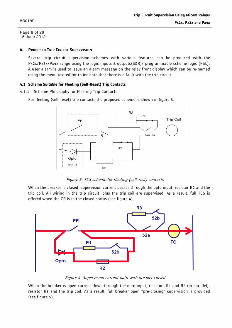
4.1.1 Scheme Philosophy for Fleeting Trip Contacts
For fleeting (self-reset) trip contacts the proposed scheme is shown in figure 3.
Figure 3: TCS scheme for fleeting (self-rest) contacts
When the breaker is closed, supervision current passes through the opto input, resistor R2 and the
trip coil. All wiring in the trip circuit, plus the trip coil are supervised. As a result, full TCS is
offered when the CB is in the closed status (see figure 4).
Figure 4: Supervision current path with breaker closed
When the breaker is open current flows through the opto input, resistors R1 and R2 (in parallel),
resistor R3 and the trip coil. As a result, full breaker open “pre-closing” supervision is provided
(see figure 5).
Trip Coil
R3
Opto
Input
R1
R2
52b
52a (n.o)
Trip Relay
52b

Trip Circuit Supervision Using Micom Relays
Px2x, Px3x and Px4x
AG019C
Page 9 of 26 15 June 2012
Figure 5: Supervision current path with breaker open
Resistors R1 and R2 are used to prevent false tripping, if the opto-input is accidentally shorted.
Resistor R3 is used to allow reset of the trip coil with latched contacts, and its value should consider
R1 and R2. It should be ensured that the series combination of R3 and R1/R2 in parallel provides
sufficient resistance to limit the current through the trip path to less than the minimum holding
current of the trip coil.
If the switchgear already has a series resistor, or other circuitry, which allows the trip coil to reset for
this condition, then the resistor R3 may not be required. However, careful consideration of the
impedance of this circuitry in comparison to the parallel combination of R1 and R2 should be made to
ensure that the opto-input will still remain energised above the set pick-up threshold.
The scheme shown in figure 2 is designed to be H7 compliant trip circuit supervision. With R1 = R2 =
2R3
4.2 Scheme Suitable for Non-Fleeting (Latched or Pulsed) Trip Contacts
4.2.1 Scheme Philosophy for non-fleeting trip contacts
In this case, the scheme of figure 2 is modified by the use of up to three additional opto inputs, as
seen in figure 6.

AG019C
Trip Circuit Supervision Using Micom Relays
Px2x, Px3x and Px4x
Page 10 of 26 15 June 2012
Figure 6: TCS scheme for non-fleeting (latched or pulsed) contacts
The basic operation for this scheme is identical to that described in section 4.1.1. The additional three
opto inputs are used to prevent a mal-indication of trip circuit failure during the time when the main
TCS opto is shorted by the main trip contact.
The first of the additional opto inputs is used to monitor any external trip signals that may be used and
is usually interfaced to the master trip (latched) relay(s). If all the trip signals are generated by the
same Px2x/Px3x/PX4x relay providing TCS, then this input is not required since the signal will be
internally generated in the PSL.
The remaining two opto inputs are used to indicate the status of the CB (open or closed) and as such,
either one or two inputs are required depending upon user preference. Obviously this CB status
information may already be available in the relay for use by other functions and as such, these
additional inputs may not be required.
In the event of a trip occurring, the relay looks for the CB being open. If it is, the TCS is temporally
disabled to prevent mal operation. However, if the CB remains closed, this would indicate a trip circuit
failure and indication is still given of this failure. Trip circuit supervision is re-enabled as soon as the
trip signals are reset, but in order to allow time for indication of a failure prior to closure of the CB, a
delay of 500ms from trip relay reset to CB close signal is required.
NOTE: TCS compliance to H7 scheme requirement is valid for P122/P123/P126/P127 Phase II
relays only.

Trip Circuit Supervision Using Micom Relays
Px2x, Px3x and Px4x
AG019C
Page 11 of 26 15 June 2012
5 HARDWARE & SOFTWARE VERSIONS OF THE MICOM PX2X, PX3X & PX4X IEDS
The following hardware and software versions of the MICOM relays are found to be compliant to
H7 scheme requirements and forms the basis of this document
The schemes presented in this document apply to Micom Px2x IEDS with Phase II hardware and
Software version 11.0. The scheme is valid for P122/P123/P126/P127 relays only.
The schemes presented in this document apply to MiCOM Px3x IEDs with version suffix 606 or
greater that have the universal, opto-isolated inputs.
The schemes presented in this document apply to MiCOM Px4x IEDs with hardware suffix C or
greater that have the universal, opto-isolated inputs. The schemes cannot be applied to Px4x IEDs
with hardware suffix A.

AG019C
Trip Circuit Supervision Using Micom Relays
Px2x, Px3x and Px4x
Page 12 of 26 15 June 2012
6 TCS DESIGN CONSIDERATION & RESISTOR CALCULATIONS IN PX2X RELAYS
6.1 Implementation
6.2 Relay Opto Details
In phase II, relays when a voltage higher than 19,2V and a current higher than 30mA are applied, the opto input
pickup and uses 35mA for a few ms then the opto consumption remains fixed at 2mA. If a current smaller than
30mA is applied, nothing happens.
6.3 Theoretical Resistance Calculations
To be fully H7 complaint with the circuit shown in figure 1, it is necessary:
At 80% and 120% of nominal voltage:
1. With the trip circuit supervision relay coil and resistors connected in series, the current through
the trip coil must not exceed 20 mA.
2. With any one component shorted with the breaker closed , the trip coil current must not exceed
60mA
With R1 = R2 = 2R3,

Trip Circuit Supervision Using Micom Relays
Px2x, Px3x and Px4x
AG019C
Page 13 of 26 15 June 2012
It should be noted for both cases that the resistance should be kept minimal to be able to cater for
item 1. With a minimum resistance, the voltage drop across the resistance and the coil is kept minimal
which mean to have more voltage across the opto input.
6.4 Configuration & Setting Logic’s (S&R) for non-fleeting trip contacts
For this scheme the opto inputs shall be used as follows:
Opto Input Application
1 (L01) Trip coil (Fig 6, Opto 15)
2 (L02) Latched external trip signal, e.g. from latching trip relay (Fig 6, opto 15)
3 (L03) CB status 52-a (Fig 6, Opto 52a)
TCS healthy (LED 7) has been defined as: L1 + L2.L3’
TCS faulty (LED 8) has been defined as: L1’.L2’ + L1’.L3
This Boolean Logic leads to the following truth table:
COIL TRIP 52a Healthy Faulty
L1 L2 L3 L1 + L2.NOT(L3) L1'.L2'+L1'.L3
0 0 0 FALSE TRUE
0 0 1 FALSE TRUE
0 1 0 TRUE FALSE
0 1 1 FALSE TRUE
1 0 0 TRUE FALSE
1 0 1 TRUE FALSE
1 1 0 TRUE FALSE
1 1 1 TRUE FALSE
Note: This logic does not raise an alarm when all 3 opto inputs are energised.

AG019C
Trip Circuit Supervision Using Micom Relays
Px2x, Px3x and Px4x
Page 14 of 26 15 June 2012

Trip Circuit Supervision Using Micom Relays
Px2x, Px3x and Px4x
AG019C
Page 15 of 26 15 June 2012

AG019C
Trip Circuit Supervision Using Micom Relays
Px2x, Px3x and Px4x
Page 16 of 26 15 June 2012

Trip Circuit Supervision Using Micom Relays
Px2x, Px3x and Px4x
AG019C
Page 17 of 26 15 June 2012
AG019C
Trip Circuit Supervision Using Micom Relays
Px2x, Px3x and Px4x
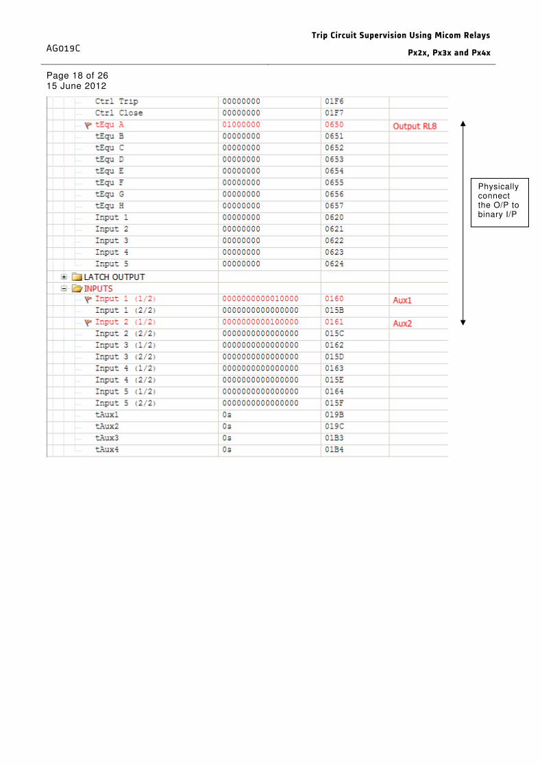
Page 18 of 26 15 June 2012
Physically connect the O/P to binary I/P

Trip Circuit Supervision Using Micom Relays
Px2x, Px3x and Px4x
AG019C
Page 19 of 26 15 June 2012
7 TCS DESIGN CONSIDERATION & RESISTOR CALCULATIONS IN PX3X RELAYS
7.1 Implementation
7.2 Relay Opto Details
The standard binary inputs available in the MICOM Px3x series are provided with a specialized Voltage
/Current characteristic , which guarantees a high degree of dependability over a wide range of the
operating voltage ranging from 24 V ... 250 V -.
At the same time for the higher operating voltage a limitation of the power loss takes place due to the
current consumption (current drain) extensively independent of the voltage. The claim is that standard
variant of binary inputs operates with any voltage from 19V. The switching threshold is actually
between 14V and 19V.
An approximate characteristic of Voltage /currents is shown here after:
7.3 Theoretical Resistance Calculations
To be fully H7 complaint with the circuit shown in figure 1, it is necessary:
At 80% and 120% of nominal voltage:
3. With the trip circuit supervision relay coil and resistors connected in series, the current through
the trip coil must not exceed 20 mA.

AG019C
Trip Circuit Supervision Using Micom Relays
Px2x, Px3x and Px4x
Page 20 of 26 15 June 2012
4. With any one component shorted with the breaker closed , the trip coil current must not exceed
60mA
With R1 = R2 = 2R3,
It should be noted for both cases that the resistance should be kept minimal to be able to cater for
item 1. With a minimum resistance, the voltage drop across the resistance and the coil is kept minimal
which mean to have more voltage across the opto input. It is better to have more voltage across the
opto input in order to be in the lower part of the characteristic shown in figure 8.

Trip Circuit Supervision Using Micom Relays
Px2x, Px3x and Px4x
AG019C
Page 21 of 26 15 June 2012
7.4 Configuration & Setting Logic’s (S&R) for fleeting/non-fleeting trip contacts
034.005 LOGICInput 6 EXT
1 151.018 OUTPFct. assignm. K 1204
034.003 LOGICInput 4 EXT
1 085.028 LEDFct. assignm. H 11
037.019 MAINParallel trip EXT
1 152.169 INPFct. assignm. U 1003
034.003 LOGICInput 4 EXT
1 152.172 INPFct. assignm. U 1004
037.019 MAINParallel trip EXT
1 152.175 INPFct. assignm. U 1005
034.005 LOGICInput 6 EXT
1 152.178 INPFct. assignm. U 1006
042.059 LOGICOutput 14 (t)
1 151.009 OUTPFct. assignm. K 1201
042.065 LOGICOutput 17 (t)
1 085.010 LEDFct. assignm. H 5
042.059 LOGICOutput 14 (t)
1 030.064 LOGICFct.assignm. outp.17
034.006 LOGICInput 7 EXT
1 152.199 INPFct. assignm. U 1201
042.067 LOGICOutput 18 (t)
1 151.012 OUTPFct. assignm. K 1202
034.006 LOGICInput 7 EXT
1 030.068 LOGICFct.assignm. outp.18
034.003 LOGICInput 4 EXT
1 151.015 OUTPFct. assignm. K 1203
034.005 LOGICInput 6 EXT
042.060 LOGICOutput 15
& 030.060 LOGICFct.assignm. outp.16
034.003 LOGICInput 4 EXT
042.062 LOGICOutput 16
1 030.052 LOGICFct.assignm. outp.14
037.019 MAINParallel trip EXT
039.011 MAINM-trip command
030.056 LOGICFct.assignm. outp.15
1

AG019C
Trip Circuit Supervision Using Micom Relays
Px2x, Px3x and Px4x
Page 22 of 26 15 June 2012
8 TCS DESIGN CONSIDERATION & RESISTOR CALCULATIONS IN PX4X RELAYS
8.1 Implementation
The schemes presented in this document apply to MiCOM Px4x IEDs with hardware suffix C or
greater that have the universal, opto-isolated inputs. The schemes cannot be applied to Px4x IEDs
with hardware suffix A.
8.2 Relay Opto Details
Px40 universal opto uses a complex pulse width modulated measurement technique to achieve low power
dissipation over the whole DC input voltage range.
8.3 Resistance Calculations
Table 1 below shows the resistor values and voltage settings required for satisfactory operation
(see ref C).
Auxiliary Voltage
(Vx)
Resistor R1 and R2
(ohms)
Resistor R3 (ohms) Opto Voltage
Setting
24/27 - - -
30/34 - - -
48/54 1.2k 0.6k 24/27
110/125 2.5k 1.2k 48/54
220/250 5.0k 2.5k 110/125
Table 1: Resistor values
NOTE: This scheme is not compatible with auxiliary supply voltages of 30/34 volts and below.
Since only one opto input is used, this scheme is not compatible with latched or pulsed (>500ms)
trip contacts without additional conditioning.

Trip Circuit Supervision Using Micom Relays
Px2x, Px3x and Px4x
AG019C
Page 23 of 26 15 June 2012
8.4 Programmable Scheme Logic for fleeting trip contacts
8.4.1 Figure 5 shows the PSL proposed for TCS when using fleeting (self-reset) contacts.
Figure 5: TCS PSL for fleeting (self-rest) contacts (model)
In the scheme, input L16 is the opto being used for the TCS. Under normal conditions, this opto
should be energised unless there is a problem with the trip path or coil.
When a trip occurs, the opto is shorted. In applications where the trip is fleeting and the CB is
open, the trip contact resets in less than 500ms, and the output will not drop off.
8.4.2 Programmable Scheme Logic for non-fleeting trip contacts
Figure 7 shows the PSL proposed for TCS when using non-fleeting (latched or pulsed) trip
contacts.
Figure 7: TCS PSL for non-fleeting (latched or pulsed) contacts (model)
In the scheme, input L16 is the opto being used for the TCS. Under normal conditions, this opto
should be energised unless there is a problem with the trip path or coil.
When a trip occurs, the opto is shorted. In applications where the trip is not fleeting (latched or
pulsed), the signal must be gated with the CB status as described in section 4.2.1.
Logic required for latched relay applications

AG019C
Trip Circuit Supervision Using Micom Relays
Px2x, Px3x and Px4x
Page 24 of 26 15 June 2012
If the trip is present (R3 – Prot’n Trip contact) and the CB is open, then this is a normal event
with latched trip relays until they are reset. The supervision is now effectively bypassed to prevent
false operation. If the trip is present and the CB is closed, there is a problem with the trip path or
coil and an alarm is generated.
As soon as the trip(s) is reset, supervision is restored providing pre-closing supervision of the CB
trip path and coil. It is imperative that at least 500ms exists between trip reset and any attempted
CB close.

Trip Circuit Supervision Using Micom Relays
Px2x, Px3x and Px4x
AG019C
Page 25 of 26 15 June 2012
9 CONCLUSIONS AND RECOMMENDATIONS
In Px30 the scheme is operationally H7 compliant for the fleeting trip contacts under normal operation
for the tested resistor values recorded in Appendix A.
With the decreased resistor values, even though Px30 is not fully compliant with the short circuit
requirements, correct operation of the opto input for the lower voltages (70% of the nominal voltage) is
maintained.
In Px20 the scheme is operationally H7 compliant for the fleeting trip contacts under normal operation
for the tested resistor values recorded in Appendix B.
With the decreased resistor values, even though P12x is not fully compliant with the short circuit
requirements, correct operation of the opto input for the voltages (>/=80% of the nominal voltage) is
maintained.
Even allowing for the limitation stated above, the scheme will always work satisfactorily, given the
parameters of the coil specified (e.g. assuming the minimum operating current is a value above the
minimum holding current provided).
Thus, a view has been taken that whilst correct operation is imperative at lower voltages, strict
compliance with the H7 short circuit requirement is not, as the resultant current levels is still only a
fraction of that level required to operate the trip coil.

AG019C
Trip Circuit Supervision Using Micom Relays
Px2x, Px3x and Px4x
Page 26 of 26 15 June 2012
VERSION DATE AUTHOR COMMENTS
A 15th
February 2008 K Srinivasan Original
B 7th
May 2012 P Newman Modified Px2x TCS logic for latched trip signals
C 15th
June 2012 Tony Hassall Conversion to Alstom format