task 8 self standing riser and coiled tubing … · 11/30/2010 · • the hazid worksheets...
TRANSCRIPT

TASK 8 SELF STANDING RISER AND COILED TUBING
INTERVENTION HAZID STUDY
Document No. 08121-1502-01.08.FINAL
Coiled Tubing, Drilling & Intervention System Using Cost Effective Vessel
RPSEA 08121-1502-01
November 30, 2010
Charles R. Yemington, PE
Project Manager Nautilus International LLC.
400 N. Sam Houston Pkwy. East, Suite 105 Houston, TX 77060

LEGAL NOTICE
This report was prepared by Nautilus International LLC. as an account of work sponsored by the Research Partnership to Secure Energy for America, RPSEA. Neither RPSEA members of RPSEA, the National Energy Technology Laboratory, the U.S. Department of Energy, nor any person acting on behalf of any of the entities: a. Makes any warranty or representation, express or implied with respect to accuracy,
completeness, or usefulness of the information contained in this document, or that the use of any information, apparatus, method, or process disclosed in this document may not infringe privately owned rights, or
b. Assumes any liability with respect to the use of, or for any and all damages resulting from the use of, any information, apparatus, method, or process disclosed in this document.
This is a final report. The data, calculations, information, conclusions, and/or recommendations reported herein are the property of the U.S. Department of Energy. Reference to trade names or specific commercial products, commodities, or services in this report does not represent or constitute and endorsement, recommendation, or favoring by RPSEA or its contractors of the specific commercial product, commodity, or service.

ABSTRACT
This report describes the results of the HAZID undertaken by Nautilus International and their associated contractors for the RPSEA Project 1502 on the Self Standing Riser (SSR) and associated Coiled Tubing operations. The HAZID was undertaken on the 13th October 2010 at the offices of Baker Hughes in Houston. The Risk Ranking of the Hazards took place on the 24th and 29th October 2010. Mr F J Deegan of Riskbytes Inc., an experienced subsea HAZID facilitator, facilitated the HAZID and produced the report. The HAZID addressed a number of issues raised by members of the HAZID team on the design and operation of the Self Standing Riser, its interface with both the DP vessel and the proposed associated Coiled Tubing operations. The Self Standing Riser system presents novel and challenging features which could possibly present hazards to the successful operation of the system once it had been installed and commissioned, and it was one of the objectives of the HAZID to identify these issues and identify the associated risks. The HAZID review process followed a classical HAZID approach as outlined in the Ref 2 Loss Prevention in the Process Industries by F P Lees. The overall HAZID review identified 43 HAZID recommendations to address hazards identified by the HAZID team.


THIS PAGE INTENTIONALLY LEFT BLANK

Project Title: Self Standing Riser and Coiled Tubing Intervention Report No 1021-10-1502-01 Project Description: HAZID of Self Standing Riser System Revision No. D Document Title: Self Standing Riser HAZID - Concept Stage Page 6 of 61
October 20, 2010
PREFACE This document presents the results of a HAZID meeting held on October 13, 2010 to review the equipment configuration and operational procedures for Coiled Tubing intervention in deepwater satellite wells using cost effective vessels and a Self Supporting Riser. Nautilus International wishes to express gratitude to Baker Hughes for hosting the HAZID meeting, Jonathan Deegan for his professional facilitation and to the individuals who participated in the meeting as representatives of the following companies: • Chevron • Shell • Hess Corporation • Baker Hughes • Halliburton • AGR Subsea • Xtreme Coil • Tidewater • Huisman • NOV CTES • General Marine Contractors • GE Oil and Gas • INTECSEA The enthusiastic and constructive participation of these individuals contributed to the success of the meeting and, we believe, to the success of the project. Comments and questions raised at the meeting are tabulated in this report. As documented in the reports for the project tasks, many of the recommendations were incorporated into the baseline design shortly after the meeting. A Phase 2 project plan will contain line item tasks to mitigate the risks and consequences for all of the remaining items, with the goal of contributing to the industry’s continued progress toward higher standards of safety and protection for personnel and the environment and enhancing production from developed reservoirs and existing production assets. All comments and recommendations will also be incorporated into the planning for a site specific demonstration.

Project Title: Self Standing Riser and Coiled Tubing Intervention Report No 1021-10-1502-01 Project Description: HAZID of Self Standing Riser System Revision No. D Document Title: Self Standing Riser HAZID - Concept Stage Page 7 of 61
October 20, 2010
RECORD OF REVISION
Document Title: Self Standing Riser and Coiled Tubing HAZID Report
Document Number: 08121-1502-01.08.FINAL Client: Nautilus International LLC. Prepared For: Chuck Yemington and Tom Williams Nautilus International Project RPSEA Project Number 08121-1502-01
REV. NO. DATE PAGES REVISED, DESCRIPTION OF CHANGE A B C D
10-20-10 11-03-10 11-05-10 11-30-10
Initial Draft for Client Comment Updated following initial Risk Ranking Exercise Updated with Risk Ranking Results Updated with comments from Nautilus International

Project Title: Self Standing Riser and Coiled Tubing Intervention Report No 1021-10-1502-01 Project Description: HAZID of Self Standing Riser System Revision No. D Document Title: Self Standing Riser HAZID - Concept Stage Page 8 of 61
October 20, 2010
TABLE OF CONTENTS
Cover Sheet ...................................................................................................................................1 Legal Notice ..................................................................................................................................2 Abstract ........................................................................................................................................3 Signature and Date Stamp .............................................................................................................4 Intentionally Left Blank Page .........................................................................................................5 Preface ..........................................................................................................................................6 Record of Revision .........................................................................................................................7 Table of Contents ..........................................................................................................................8 Acronyms & Abbreviations .......................................................................................................... 10 Executive Summary ..................................................................................................................... 11
1.0 INTRODUCTION .................................................................................................................... 13
1.1 Overview of the SSR and CT Intervention ........................................................................... 13
1.2 Self Standing Riser and Coiled Tubing Equipment Description ............................................. 15
1.3 Scope of the Study ............................................................................................................ 16
1.4 Objectives of the HAZID Process ........................................................................................ 16
1.5 Aims of the HAZID Meeting ............................................................................................... 17
1.6 Boundaries of the HAZID ................................................................................................... 17
1.7 HAZID Team Members....................................................................................................... 17
1.8 Quality of the HAZID ......................................................................................................... 19
2.0 HAZID METHODOLOGY ......................................................................................................... 20
3.0 SELF STANDING RISER HAZID RESULTS ................................................................................... 23
4.1 Risk Priority Rankings ........................................................................................................ 29
4.2 Risk Ranking Team Members ............................................................................................. 30
5.0 OVERALL CONCLUSIONS ........................................................................................................ 32
5.1 Conclusions of the SSR System HAZID ................................................................................ 32

Project Title: Self Standing Riser and Coiled Tubing Intervention Report No 1021-10-1502-01 Project Description: HAZID of Self Standing Riser System Revision No. D Document Title: Self Standing Riser HAZID - Concept Stage Page 9 of 61
October 20, 2010
List of Figures
Figure 1 - Overview of Self Standing Riser System ..................................................................................... 14 Figure 2 - Interface of the Self Standing Riser with the Coiled Tubing at the Vessel ................................. 15 Figure 3 - HAZID Process ............................................................................................................................. 21
List of Tables
Table 1 - List of HAZID Attendees ............................................................................................................... 18 Table 2 - SSR HAZID Guidewords ................................................................................................................ 22 Table 3 - Self Standing Riser HAZID Recommendations ............................................................................. 25
List of Appendices
Appendix I Self Standing Riser HAZID Worksheets Appendix II HAZID Terms of Reference
Appendix III Chevron Risk Assessment Matrices Appendix IV Hazard Consequence Categories
References ‘Loss Prevention in the Process Industries’, Second Edition: Hazard Identification, Assessment and Control. F P Lees

Project Title: Self Standing Riser and Coiled Tubing Intervention Report No 1021-10-1502-01 Project Description: HAZID of Self Standing Riser System Revision No. D Document Title: Self Standing Riser HAZID - Concept Stage Page 10 of 61
October 20, 2010
ACRONYMS & ABBREVIATIONS ALARP As Low As Reasonably Practicable BOP Blow Out Preventer CT Coiled Tubing DP Dynamic Positioning FEED Front End Engineering Design HAZID HAZard IDentification HAZOP HAZard & OPerability Analysis HSE Health, Safety, Environment RPSEA Research Partnership to Secure Energy for America ROV Remotely Operated Vehicle SIMOPs Simultaneous Operations SSD Seafloor Shutoff Device SSR Self Supporting Riser VIV Vortex Induced Vibration

Project Title: Self Standing Riser and Coiled Tubing Intervention Report No 1021-10-1502-01 Project Description: HAZID of Self Standing Riser System Revision No. D Document Title: Self Standing Riser HAZID - Concept Stage Page 11 of 61
October 20, 2010
EXECUTIVE SUMMARY This report describes the results of the HAZID undertaken by Nautilus International and their associated contractors for the RPSEA Project 1502 on the Self Standing Riser (SSR) and associated Coiled Tubing operations. The HAZID was undertaken on the 13th October 2010 at the offices of Baker Hughes in Houston. The Risk Ranking of the Hazards took place on the 24th and 29th October 2010. Mr F J Deegan of Riskbytes Inc., an experienced subsea HAZID facilitator, facilitated the HAZID and produced the report. The HAZID addressed a number of issues raised by members of the HAZID team on the design and operation of the Self Standing Riser, its interface with both the DP vessel and the proposed associated Coiled Tubing operations. The Self Standing Riser system presents novel and challenging features which could possibly present hazards to the successful operation of the system once it had been installed and commissioned, and it was one of the objectives of the HAZID to identify these issues and identify the associated risks. The HAZID review process followed a classical HAZID approach as outlined in the Ref 2 Loss Prevention in the Process Industries by F P Lees. The overall HAZID review identified 43 HAZID recommendations to address hazards identified by the HAZID team. Overall Conclusions The Self Standing Riser system HAZID exercise brought together 24 members of Nautilus International and the project team and representatives from operating companies and associated service contractors in a structured format of a formal HAZID. Concise documents on system configuration and operational procedures were provided to the attendees for advance reading. The participants had a wide variety of knowledge and experience of subsea systems design and operation including offshore Coiled Tubing operations, they and provided a positive contribution to the overall HAZID process. Therefore, it can be concluded that at this stage of the HAZID process, subject to the resolution of the recommendations the following objectives have been achieved: • A systematic and comprehensive review of critical issues associated with the Self Standing Riser
system design and the associated operations from a DP vessel with coiled tubing has been undertaken.
• The HAZID worksheets provide a complete and comprehensive record of the study teams thinking and conclusions drawn by the team.
• This was not the first time that the concept of the SSR had been formally reviewed in a Hazard Identification forum and it was acknowledged by the team that the process was a useful exercise in the overall design process.
• The majority of the hazard and operability issues identified by the team concerned operability (Downtime and Associated costs) of using the system.
• The environmental risks identified associated with the SSR system are inherent in any subsea intervention system design.

Project Title: Self Standing Riser and Coiled Tubing Intervention Report No 1021-10-1502-01 Project Description: HAZID of Self Standing Riser System Revision No. D Document Title: Self Standing Riser HAZID - Concept Stage Page 12 of 61
October 20, 2010
It is the conclusion of the HAZID facilitator that once the HAZID recommendations have been effectively closed out it can be concluded that the initial hazard should have been effectively managed as part of the concept design process. As the SSR system is still only at an early stage it is recommended that as the design progresses then further HAZID and HAZOP exercises should be scheduled as part of the assurance process. The following is a proposed list of further exercises that should be considered. 1. Load out and installation of the SSR at the field location using a vessel of opportunity. This should
be completed early in the FEED stage once the vessels particulars and equipment configurations have been developed.
2. Load out and Rig up of the Coiled Tubing Equipment on the specialist vessel. This HAZID should be completed during the early FEED stage once details of the dedicated well service vessel have been defined and equipment configurations have been preliminary laid out.
3. Conduct a formal HAZOP of the proposed CT operations using a proposed well, SSR fluid flow diagrams. This should be undertaken at a point in the FEED design stage when the equipment configurations (Layouts and Subsea Shut-in Device and Coiled Tubing Shear Seal device have been finalized).
4. A dedicated Pre-operational HAZID once the detailed design stage of the project has been completed and a specific well intervention has been identified and dedicated operational procedures have been developed.

Project Title: Self Standing Riser and Coiled Tubing Intervention Report No 1021-10-1502-01 Project Description: HAZID of Self Standing Riser System Revision No. D Document Title: Self Standing Riser HAZID - Concept Stage Page 13 of 61
October 20, 2010
1.0 INTRODUCTION This report describes the HAZID led by Mr F J Deegan of Riskbytes Inc. of the RPSEA Project 08121-1502 Self Standing Riser system design and operation. The HAZID was held at the offices of Baker Hughes on the 13th October 2010. The following section describes the SSR system which was reviewed during the HAZID including pertinent design and operations issues associated with the SSR system.
1.1 Overview of the SSR and CT Intervention
The objective of the SSR CT intervention system which is the subject of RPSEA project 1502 is to develop a practical, cost effective downhole intervention system for deep water satellite subsea wells using a modular, reusable Self Supporting Riser (SSR) and a cost effective (non-MODU) intervention vessel. The concept is for the SSR to extend the well casing up from the seafloor so that existing shallow water intervention systems can be used in ultra deep water. The plan is to install and recover the SSR from a basic construction work boat independently from the downhole operation. The concept of the SSR is that it can be quickly and safely abandoned and left untended when downhole operations are complete or when forced by weather, storm threat, or equipment problems. Once the SSR is installed by the installation vessel then the larger intervention vessel (~300ft offshore support vessel) will be loaded out with the coiled tubing intervention equipment and sail to the location to undertake the actual coiled tubing intervention operation. When interventions are on-going the intervention vessel is also free to depart at convenient times during the work without having to pull the riser. The riser can be recovered at a later more opportune time. One of the primary advantages of the design is that it improves the fatigue life of the coiled tubing by reducing flexure and avoiding flexing where the tubing is exposed to salt water. In the event of a DP system failure or other emergency the reservoir can be shut in at the seafloor through a Seafloor Shut-in device (SSD) as well as a Shear-seal device located near the surface (Possibly a Coiled Tubing BOP) with associated disconnect point above the upper shear seal device. This configuration should then allow the intervention vessel free to depart within a short period of time of the signal been given to disconnect. A schematic of the system is shown in Figures 1 and 2.

Project Title: Self Standing Riser and Coiled Tubing Intervention Report No 1021-10-1502-01 Project Description: HAZID of Self Standing Riser System Revision No. D Document Title: Self Standing Riser HAZID - Concept Stage Page 14 of 61
October 20, 2010
FIGURE 1 - OVERVIEW OF SELF STANDING RISER SYSTEM
Near Surface Shear & Seal
Buoyancy
Stress joint
Seafloor shutoff
SSR connector Existing tree or wellhead
Riser Extension

Project Title: Self Standing Riser and Coiled Tubing Intervention Report No 1021-10-1502-01 Project Description: HAZID of Self Standing Riser System Revision No. D Document Title: Self Standing Riser HAZID - Concept Stage Page 15 of 61
October 20, 2010
FIGURE 2 - INTERFACE OF THE SELF STANDING RISER WITH THE COILED TUBING AT THE VESSEL
1.2 Self Standing Riser and Coiled Tubing Equipment Description
The following section provides a brief overview of the equipment covered by the Self Standing Riser and Coiled Tubing HAZID.
1.2.1 Self Standing Riser
The self standing riser consists of a Subsea Shut in Device (Two Ram Package), associated lengths of casing or 6-5/8” drill pipe, buoyancy modules, near surface isolation device (Coiled Tubing Shear Seal Device) and a near surface disconnect point. In addition to the SSR there is an additional riser length of between 100ft to 300ft which connects to the SSR at the near surface disconnect point and terminates in the moonpool of the well service vessel at a dedicated motion isolation system. At this stage the motion isolation system is being specified.
1.2.2 Control Umbilicals
The self standing riser has a requirement for two independent umbilicals for control of various aspects of the system. There will be a dedicated control umbilical for control of the Subsea Shut-in Device and the associated subsea tree. In addition there will be a separate control umbilical for the operation of the near surface shear seal device and the riser disconnect system. To minimize the risk of accidental actuation, ROV operation is used instead of umbilicals to the extent practical.
Support cylinders
Small moon pool
Riser extension
Injector

Project Title: Self Standing Riser and Coiled Tubing Intervention Report No 1021-10-1502-01 Project Description: HAZID of Self Standing Riser System Revision No. D Document Title: Self Standing Riser HAZID - Concept Stage Page 16 of 61
October 20, 2010
1.2.3 Coiled Tubing Equipment
The coiled tubing equipment mounted on the well service vessel consists of a coiled tubing reel, frame to support the coiled tubing, goose neck and injector head, motion isolation system and connection to the upper riser system. In addition there will be associated tanks and power packs which are required to support the coiled tubing intervention operation. The design of the actual configuration of the vessel equipment will depend on the tasks to be done and the preferences of the operator and the service contractor.
1.2.4 Well Service Vessel
The well service vessel to be used for the coiled tubing intervention will be a DP 2 class vessel of overall length of approximately 300 ft. The vessel will provide sufficient deck space to mount the coiled tubing equipment and provide sufficient accommodation for the crews.
1.3 Scope of the Study
This HAZID review covered certain particular operations associated with coiled tubing operations interfacing with the SSR. The HAZID did not address issues surrounding the rig up or rig down of either the SSR or the coiled tubing equipment. The installation of the SSR was addressed informally in a preparatory meeting and found to be essentially a construction activity with little risk of hydrocarbon release. The project team felt that Coiled Tubing activities were not sufficiently defined to perform a meaningful HAZID at this time. The SSR system at present is configured for interventions on horizontal subsea trees with up to 4 inch production tubing and all vertical subsea trees. The HAZID concentrated on vertical tree operation.
1.4 Objectives of the HAZID Process The following objectives were agreed with the Nautilus Team members prior to the HAZID:
• To identify critical high level risks associated with the CT Intervention Riser System,
including the interface with DP vessels and the issues around CT operations on a ‘live’ well.
• Assess whether the hazard scenarios identified and their associated risk present a level of risk which can be managed to ALARP.
• Provide a list of actions items to be addressed in the FEED stage of the RPSEA 1502 project where further analysis and/or engineering work is required.
• Provide a complete and comprehensive record of the study teams thinking and conclusions drawn during each study session.

Project Title: Self Standing Riser and Coiled Tubing Intervention Report No 1021-10-1502-01 Project Description: HAZID of Self Standing Riser System Revision No. D Document Title: Self Standing Riser HAZID - Concept Stage Page 17 of 61
October 20, 2010
1.5 Aims of the HAZID Meeting The SSR HAZID has the following aims with specific reference to the following: • Undertake a structured and comprehensive review of the concept of the SSR system
using a formal Hazard Identification (HAZID) process to identify and develop specific hazard scenarios associated with the SSR system.
• Provide a complete, clearly stated list of hazard scenarios, which originate from the systems studied that have the potential to affect the safety of the facility including personnel, 3rd party stakeholders, regulators and the environment.
• Assess the risk associated with the individual hazard scenarios. • Provide a list of actions in terms of specific design, operational or procedural
changes or additional studies to further understand the identified hazards and reduce the associated risk.
• Provide guidance to the management of the SSR project for the purposes of Risk Management as the project moves forward to the FEED stage.
• Provide assurance that, once all the follow up activities have been verified as satisfactorily completed, all identified hazards and design and operability problems have been eliminated or can be managed to a level that is As Low as Reasonably Practicable (ALARP).
• Provide a complete and comprehensive record of the study teams thinking and conclusions drawn during each of the study sessions in a formal HAZID report.
1.6 Boundaries of the HAZID
The following are the boundary conditions for the HAZID: • To identify the HIGH LEVEL issues associated with the CT Intervention Riser System,
including issues around the following CRITICAL ACTIVITIES: Riser Disconnects - Planned and Unplanned. Inadvertent Disconnect of the Riser. Riser Integrity issues. Well Control Issues when using SSR System Other Risk Issues - Metocean Equipment Problems etc
1.7 HAZID Team Members
The SSR CT Intervention HAZID was undertaken on the 13th of October 2010 at the offices of Baker Hughes Houston, Texas. As the HAZID process is a team exercise, the following personnel from the RPSEA 1502 project team, its associated contracting companies, representatives from down hole intervention contractors, as well as representatives from several sponsoring operators were assembled to participate in the HAZID process.

Project Title: Self Standing Riser and Coiled Tubing Intervention Report No 1021-10-1502-01 Project Description: HAZID of Self Standing Riser System Revision No. D Document Title: Self Standing Riser HAZID - Concept Stage Page 18 of 61
October 20, 2010
TABLE 1 - LIST OF HAZID ATTENDEES = FULL TIME P/T = PART TIME
NAME COMPANY ROLE/SPECIALIZATION YRS EXPERIENCE
PRE-MEETING
DAY 1
Thomas Williams Nautilus
International Project Administrator 41
JG Nutter XTREME Coil David Traugott NOV CTES Robert van Kuilenburg Huisman U.S. John H. Cohen AGR Subsea Inc. R&D Technology Manager 37 Dana Witt Chevron Sr Drilling Advisor Shafiq Khandoker Hess Corp P/T
Chuck Yemington Nautilus
International Managing Director Nautilus Int.
33
Perry Courville Halliburton Group Manager CT and Hydraulic Workover
31
Colin Morris Shell P/T
Dr.Keith Millheim Nautilus
International Designer/Engineer of Self Standing Riser
40
David Manning Tidewater Manager of Engineering 22
Jim Yu INTECSEA Manager Tendons and Risers
23
Tony Moore GE O & G Martin Davidson GMC System Specifications 28 Iain Duncan GMC System Specifications 31
Eugene Ratterman Baker Hughes Well Completion Pumping and Intervention
20
Vance Nixon GE O & G Project Manager 20
Cort Peavy Baker Hughes Product Line Manager Subsea Intervention
12
Ray Staiwicz Chevron Global Intervention Manager
Teresa Harlow Nautilus
International HAZID Scribe
T J Maa GE O & G Ryan Stigberg INTECSEA Jonathan Deegan Riskbytes Inc HAZID Facilitator 25

Project Title: Self Standing Riser and Coiled Tubing Intervention Report No 1021-10-1502-01 Project Description: HAZID of Self Standing Riser System Revision No. D Document Title: Self Standing Riser HAZID - Concept Stage Page 19 of 61
October 20, 2010
1.8 Quality of the HAZID
The HAZID was undertaken at a point in the concept stage of the SSR project where Nautilus International and their associated contractors had produced sufficient design details to enable a formal high level HAZID process to be undertaken. Following the HAZID the HAZID facilitator has commented on the quality of the HAZID process: • The HAZID process has provided a thorough process for the review of the SSR
system at the concept stage with respect to particular operations that were reviewed and issues associated with the SSR.
• The various project team members have been able to gain a thorough understanding of particular interfaces in the system.
• A number of significant issues regarding the use of the SSR with Coiled Tubing and a DP vessel were identified and potential solutions identified. These solutions will need to be assessed during the FEED stage of the design.
Given the above points the following conclusions can be drawn: • A thorough and comprehensive HAZID of the SSR system with respect to particular
operations has been undertaken. • The team members assembled for the HAZID were able to provide valuable input
into the design through the HAZID process. • No significant HSE issues regarding the design of the SSR system, were identified
which would prevent the design from moving forward. • Failure modes/Hazards were identified which could result in significant downtime
and associated costs to the operation. Given these factors and the length of time provided to undertake the study it is concluded that the systems covered by the HAZID have been adequately addressed.

Project Title: Self Standing Riser and Coiled Tubing Intervention Report No 1021-10-1502-01 Project Description: HAZID of Self Standing Riser System Revision No. D Document Title: Self Standing Riser HAZID - Concept Stage Page 20 of 61
October 20, 2010
2.0 HAZID METHODOLOGY A HAZID study is a facilitated review by a multi-disciplinary team of engineering design operation and procedures in order to identify hazards and possible operability problems and their potential consequences. The SSR HAZID process commenced when a team of RPSEA 1502 project personnel and contractors met one day before the formal HAZID meeting to review the proposed areas that the HAZID would review. This meeting was attended by the contractor team members as shown in Table 1. The meeting went through a series of presentations showing the different operations that were proposed for installation, operation and removal of the SSR system. The meeting provided the opportunity for team members to raise and discuss issues concerning the SSR system. From the meeting the following operations were identified as being the most relevant with respect to discussion at the formal HAZID meeting planned for the next day. • Riser Disconnects - Planned and Unplanned. • Inadvertent Disconnect of the Riser. • Riser Integrity issues. • Well Control Issues when using SSR System • Other Risk Issues - Metocean and Equipment Problems Based upon these critical operations the HAZID process was tailored around the above. At the HAZID meeting the process used was for the Nautilus International project lead to provide a presentation of the design and operation to the team on a particular aspect. Once the presentation was completed then meeting was opened up to questions and then to undertake the formal HAZID of the issues using the format shown in the following diagram. The table of guidewords shown in Table 2 was used by the team as an aide-memoire to stimulate thinking and aid in the identification of issues.

Project Title: Self Standing Riser and Coiled Tubing Intervention Report No 1021-10-1502-01 Project Description: HAZID of Self Standing Riser System Revision No. D Document Title: Self Standing Riser HAZID - Concept Stage Page 21 of 61
October 20, 2010
FIGURE 3 - HAZID PROCESS
IDENTIFY OPERATION BEING REVIEWED
SCENARIO HAZARD
IS IT POSSIBLE IS IT LIKELY?
BRAINSTORM THREATS AND CAUSES
NO
YES
ASSESS
ARE ADDITIONAL SAFEGUARDS REQUIRED?
CONTROLS WHAT CONTROLS OR BARRIERS CONTROL OR RECOVER FROM
THE EFFECT?
YES
RECORD RECOMMEND ADDITIONAL
SAFEGUARDS
NO

Project Title: Self Standing Riser and Coiled Tubing Intervention Report No 1021-10-1502-01 Project Description: HAZID of Self Standing Riser System Revision No. D Document Title: Self Standing Riser HAZID - Concept Stage Page 22 of 61
October 20, 2010
TABLE 2 - SSR HAZID GUIDEWORDS
GUIDEWORD (KEY WORD) EXPLANATION Met-ocean Issues Loop Current Loop currents affects the riser when deployed Vortex Induced Vibration VIV affects the riser when deployed Seabed currents High seabed currents affect the riser Hurricane abandonment Hurricane is approaching the area of operations Riser Failure Modes External Corrosion External corrosion of the riser Internal Corrosion Internal corrosion on the riser Loss of Surface Tension Failure of Surface Tensioner System Loss of Riser Buoyancy Failure of the Riser Buoyancy System Damage to riser internals Gouging of the riser or wear due to contact on internal surface Loss of Containment Failure of the Riser e.g. connector failure crack propagation Fatigue of the riser Fatigue of the riser due to prolonged exposure Control System or Service Supply Issues Inadvertent Disconnect The Riser inadvertently disconnects from the subsea tree Unable to isolate Control System failure results in failure to isolate the well Loss of Services to Equipment Loss of air or electrical power to equipment from vessel Loss of Communications Loss of communications with Subsea Equipment Communications Failure Failure of Communications on Vessel Handling Issues Deck Space Restrictive deck space on vessel Deck Loading Limited deck loading capacity Lifting equipment Crane capacities, crane operating arcs, Dropped Objects Dropped Object to deck or to subsea Pressure stored Energy Working around pressure and stored energy Vessel motions Working on deck with motions of 300 ft vessel Vessel Hazards Loss of DP Loss of DP Position - Drive Off - Drift Off - Force Off Fire on Vessel Fire or other emergency on vessel Loss of Vessel Stability Loss of the vessel stability while on operations Other Hazards Errant Vessel Errant vessel in close proximity to SSR operation SIMOPs Simultaneous Operations (Production, Construction etc). Environmental Issues Handling Hydrocarbons Hydrocarbons at surface or hydrocarbon contaminated fluid Spills Spill of chemicals or well fluids Regulatory Issues Changes in Legislation Changes in regulations in Gulf of Mexico Technology and Project Issues New or Un-proven Technology Project using new or unproven technology or technology step outs Design Uncertainty Project has design uncertainties pressures, temperatures fluid types etc

Project Title: Self Standing Riser and Coiled Tubing Intervention Report No 1021-10-1502-01 Project Description: HAZID of Self Standing Riser System Revision No. D Document Title: Self Standing Riser HAZID - Concept Stage Page 23 of 61
October 20, 2010
3.0 SELF STANDING RISER HAZID RESULTS The HAZID of the SSR system generated a total of 43 recommendations. These recommendations are outlined in the table below. The format of the tables is as follows: • First column is the recommendation number. • Second column contains the cause of the recommendations • The third column is the recommendation categorization either Operability or HSE, • The fourth column is the responsible discipline engineer for addressing the
recommendation.


Project Title: Self Standing Riser and Coiled Tubing Intervention Report No 1021-10-1502-01 Project Description: HAZID of Self Standing Riser System Revision No. D Document Title: Self Standing Riser HAZID - Concept Stage Page 25 of 61
October 20, 2010
TABLE 3 - SELF STANDING RISER HAZID RECOMMENDATIONS
NO CAUSE OF HAZARD RECOMMENDATION ACTIONEE SSR Disconnect and Reconnect
1 Shear seal - riser disconnect SSD consists of shear ram on top blind ram on bottom review configuration of SSD for isolation on shearing of equipment across it.
GE Oil & Gas
2 Shear seal - riser disconnect Make the shear ram capable of cutting all tools that could be across it.
GE Oil & Gas
3 Shear seal - riser disconnect Procedures to ensure that on planned disconnect procedures will allow the riser to be sealed.
Nautilus International
4 Coil Tubing is sheared Review system for worst case weight loss due to shearing of coil and load path reacts.
Nautilus International
5 Coil Tubing is sheared As part of design, ensure that anti recoil valves are activated prior to shearing.
Nautilus International
6 Vessel loss of station keeping Review requirement for extra protection that DP3 would provide and assess whether the additional costs provide a risk benefit.
Nautilus International
7 Coil sheared at upper shear point only (alternate shear point)
Assess whether SSD will require an acoustic activation system.
Nautilus International
8 Coil sheared at upper shear point only (alternate shear point)
Review system configuration to enable fishing of sheared coil under various sizes
Nautilus International
9 Failure to shear at subsea SSD Assess configuration of upper shear point for adequate level of redundancy and reliability.
GE Oil & Gas
10 Failure to shear at subsea SSD Evaluate SSD and tree valve closure sequence and timing and shearing
GE Oil & Gas
11 Unknown well conditions below shear point [upper shear seal point]
Review specification of upper shear point to allow for monitoring of pressures and ability to circulate.
Nautilus International
12 Unknown well conditions below shear point [upper shear seal point]
Develop SSR CT intervention well control procedures
Nautilus International
13 Unknown well conditions below shear point (SSD).
Prior to opening of SSD appropriate procedures should be followed to assess well bore conditions below SSD.
Nautilus International
14 Unknown well conditions below shear point (SSD).
Further develop circulating hose and monitoring device specification as project progresses
Nautilus International
15 Failure to shear at upper shear point
Investigate possibility of installing surface shear device for coil
Nautilus International
Project Title: Self Standing Riser and Coiled Tubing Intervention Report No 1021-10-1502-01 Project Description: HAZID of Self Standing Riser System Revision No. D Document Title: Self Standing Riser HAZID - Concept Stage Page 26 of 61
October 20, 2010
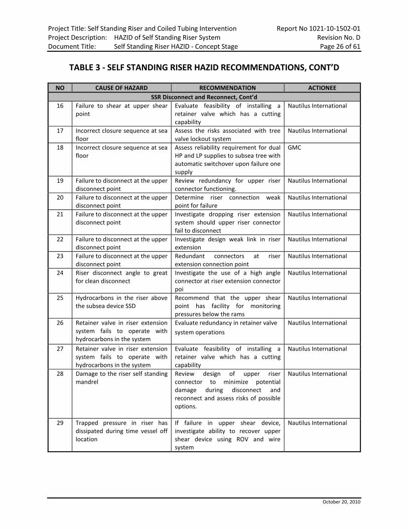
TABLE 3 - SELF STANDING RISER HAZID RECOMMENDATIONS, CONT’D
NO CAUSE OF HAZARD RECOMMENDATION ACTIONEE SSR Disconnect and Reconnect, Cont’d
16 Failure to shear at upper shear point
Evaluate feasibility of installing a retainer valve which has a cutting capability
Nautilus International
17 Incorrect closure sequence at sea floor
Assess the risks associated with tree valve lockout system
Nautilus International
18 Incorrect closure sequence at sea floor
Assess reliability requirement for dual HP and LP supplies to subsea tree with automatic switchover upon failure one supply
GMC
19 Failure to disconnect at the upper disconnect point
Review redundancy for upper riser connector functioning.
Nautilus International
20 Failure to disconnect at the upper disconnect point
Determine riser connection weak point for failure
Nautilus International
21 Failure to disconnect at the upper disconnect point
Investigate dropping riser extension system should upper riser connector fail to disconnect
Nautilus International
22 Failure to disconnect at the upper disconnect point
Investigate design weak link in riser extension
Nautilus International
23 Failure to disconnect at the upper disconnect point
Redundant connectors at riser extension connection point
Nautilus International
24 Riser disconnect angle to great for clean disconnect
Investigate the use of a high angle connector at riser extension connector poi
Nautilus International
25 Hydrocarbons in the riser above the subsea device SSD
Recommend that the upper shear point has facility for monitoring pressures below the rams
Nautilus International
26 Retainer valve in riser extension system fails to operate with hydrocarbons in the system
Evaluate redundancy in retainer valve system operations
Nautilus International
27 Retainer valve in riser extension system fails to operate with hydrocarbons in the system
Evaluate feasibility of installing a retainer valve which has a cutting capability
Nautilus International
28 Damage to the riser self standing mandrel
Review design of upper riser connector to minimize potential damage during disconnect and reconnect and assess risks of possible options.
Nautilus International
29 Trapped pressure in riser has dissipated during time vessel off location
If failure in upper shear device, investigate ability to recover upper shear device using ROV and wire system
Nautilus International

Project Title: Self Standing Riser and Coiled Tubing Intervention Report No 1021-10-1502-01 Project Description: HAZID of Self Standing Riser System Revision No. D Document Title: Self Standing Riser HAZID - Concept Stage Page 27 of 61
October 20, 2010
TABLE 3 - SELF STANDING RISER HAZID RECOMMENDATIONS, CONT’D
NO CAUSE OF HAZARD RECOMMENDATION ACTIONEE Inadvertent Disconnect
30 Inadvertent disconnect of upper riser connector with common umbilical providing power and signal to retainer valve, connector, upper shear seal system, SSD and subsea tree.
Do not configure the riser system umbilical into a common system where single point failure could result in possible well control.
GMC
31 Inadvertent disconnect of upper riser connector with two umbilicals one providing power and signal to retainer valve, connector, upper shear seal system, and independent umbilical providing power and signal to SSD and subsea tree.
Review design function of upper shear system to insure well integrity upon disconnect of riser extension connector
Nautilus International
32 Inadvertent disconnect of upper riser connector with two umbilicals one providing power and signal to retainer valve, connector, upper shear seal system, and independent umbilical providing power and signal to SSD and subsea tree.
Protocols need to be developed for loss of station keeping and inadvertent disconnect of riser
Nautilus International
33 Inadvertent disconnect of upper riser connector with two umbilicals one providing power and signal to retainer valve, connector, upper shear seal system, and independent umbilical providing power and signal to SSD and subsea tree.
Ensure functions which could result in an advertent disconnect are secured
Nautilus International
34 Inadvertent operation of lower SSD connector
SSD to tree connector to be configured for ROV actuation only.
GE Oil & Gas
35 Inadvertent operation of lower SSD connector
Ensure that detail reviews are undertaken for tree to SSD connector system for potential failure resulting in disconnect
Nautilus International
36 Inadvertent operation of lower SSD connector
Examine possible methods for riser retention should inadvertent disconnect occur
Nautilus International
37 Inadvertent operation of lower SSD connector
Examine potential for interlock from tree to SSD to prevent inadvertent disconnect
Nautilus International

Project Title: Self Standing Riser and Coiled Tubing Intervention Report No 1021-10-1502-01 Project Description: HAZID of Self Standing Riser System Revision No. D Document Title: Self Standing Riser HAZID - Concept Stage Page 28 of 61
October 20, 2010
TABLE 3 - SELF STANDING RISER HAZID RECOMMENDATIONS, CONT’D
NO CAUSE OF HAZARD RECOMMENDATION ACTIONEE Riser Integrity
38 Corrosion Assess requirements for corrosion protection on riser
Nautilus International
39 Corrosion Develop corrosion compatibility system for riser
Nautilus International
40 Fatigue Evaluate system for mitigating fatigue issues, i.e., strakes, fairings, buoyancy elevation and drill string tracking system
INTECSEA Nautilus International
41 Washing out Analyze makeup equipment to prevent damage to connections [dedicated pipe handling equipment on installation vessel]
Nautilus International
42 Gouging Investigate whether internals of riser need to be coated to prevent damage due to erosion caused by sand, corrosion, etc.
Nautilus International
43 Hydrate formation in riser Develop protocol for hydrate remediation
Nautilus International
Equipment Layout on Vessel 44 Handling pipe on vessel Ensure that appropriate pipe handling
equipment is used to handle pipe on the installation vessel.
Nautilus International

Project Title: Self Standing Riser and Coiled Tubing Intervention Report No 1021-10-1502-01 Project Description: HAZID of Self Standing Riser System Revision No. D Document Title: Self Standing Riser HAZID - Concept Stage Page 29 of 61
October 20, 2010
4.0 HAZID RISK RANKING EXERCISE
As part of the HAZID review process, the individual HAZID entries were assessed using a qualitative risk ranking methodology. The methodology chosen was the Chevron RiskMan matrix system for Safety and Environment issues and the Chevron Drilling and Completions (D&C) Reliability and Efficiency Matrix for downtime and costs events. The matrices are provided in Appendix III. The aim of the ranking process is two-fold namely: • To rank any hazards in the system design, thus allowing appropriate design, engineering and
procedural measures to be implemented to either eliminate, control or mitigate the potential hazards and consequences.
• To provide an overall risk picture for the SSR system design. As part of the Risk Ranking exercise a series of potential time and cost estimates were developed to allow the risk ranking group to determine the different levels of consequences based upon the agreed listing. The agreed list of consequences is provided in Appendix IV. As stated above the probability of the consequences manifesting themselves during a proposed operation of the SSR riser used the Chevron Reliability and Efficiency Matrix probabilities for the downtime and cost events. The Chevron R&E process is based upon a single well operational scenario, therefore for the SSR CT Intervention riser system the team based the probability estimates of an event occurring on a single well intervention operation. It can be stated that the general nature of the events developed in the HAZID are sometimes low probability events. Thus by the nature of many of the events that were risk ranked many were ranked as Low Probability (<5%) which when assessed on the basis of a short duration (<14 to 21 day) operation. It should be noted that many of the hazards identified could have catastrophic consequences in terms of downtime and costs and are ranked high in terms of consequences (<3 on the Chevron Scale). This combination generally results in the risks appearing to be ‘low’ on the matrix. This is not unexpected for short duration operations where the exposure to the hazard is limited in terms of time, but over a life time of the riser one or more events could very well be expected to occur. This fact should be taken into account when reviewing the results of the risk assessment. 4.1 Risk Priority Rankings
The HSE Risk Prioritization Matrix rankings are numbered and aligned with associated required actions for health, environment and safety risks, these include: • 1, 2, 3, 4 - Short-term, interim risk reduction required. Long term risk reduction plan
must be developed and implemented. • 5 - Additional long term risk reduction required. If no further action can be
practicably taken, management approval must be sought to continue the activity.

Project Title: Self Standing Riser and Coiled Tubing Intervention Report No 1021-10-1502-01 Project Description: HAZID of Self Standing Riser System Revision No. D Document Title: Self Standing Riser HAZID - Concept Stage Page 30 of 61
October 20, 2010
4.1 Risk Priority Rankings, Cont’d • 6 - Risk is tolerable if reasonable safeguards / managements systems are confirmed
to be in place and consistent with relevant Risk Reduction Procedure Guidelines. • 7, 8, 9, 10 - No further risk reduction required. Additional risk reduction will be
implemented if required. The Reliability and Efficiency Risk Prioritization Matrix rankings are numbered and aligned with associated required actions the estimated level of risk: • 1, 2, 3, 4 - Avoid - this response indicates that changes to the project plan and
safeguards will be developed to eliminate the risk or to protect the project/well. • 5 - Mitigate - The response indicates that additional safeguards are needed and will
be implemented to reduce the likelihood or consequences of the risk event to an acceptable level. The risk is not eliminated but alleviated.
• 6 - Accept or Mitigate - The response indicates that the safeguards in place may be adequate. Risk Reduction is at Management team discretion.
• 7, 8, 9, 10 - Accept - Further risk reduction is at management team discretion.
4.2 Risk Ranking Team Members The following core team of the SSR CT HAZID team assembled on two separate occasions to undertake the risk ranking exercise
NAME POSITION 24-OCT-10 29-OCT-10
Chuck Yemington Project Manager SSR System ● Martin Davidson System Specification SSR System ● ● Iain Duncan System Specification SSR System ● ● Lane Osburn Subsea Controls and Completions ● ● Jonathan Deegan Risk Ranking Expert ● ● Tom Williams Project Administrator Part Time
4.3 Risk Ranking Results
Due to the nature of a subsea well and associated seabed architecture the following results of the risk ranking exercise can be concluded. • The risk ranking exercise allowed a core team of provided valuable input into the
potential consequences and probabilities.

Project Title: Self Standing Riser and Coiled Tubing Intervention Report No 1021-10-1502-01 Project Description: HAZID of Self Standing Riser System Revision No. D Document Title: Self Standing Riser HAZID - Concept Stage Page 31 of 61
October 20, 2010
4.3 Risk Ranking Results, Cont’d
• The vast majority of the hazard identified with associated downtime and cost consequences were ranked in the range 7 to 10 on the Reliability and Efficiency Matrix. This indicates that the design is relatively robust with respect to the identified risks. It must be stated though that the risks ranked above were based upon a short duration operational scenarios. The short duration operational scenarios which have a significant effect on the likelihood of the identified hazard events occurring. Therefore it must be noted that although the risks were generally considered to be low this does not preclude the requirement for undertaking the actions identified by the HAZID team at the discretion of the SSR Project team.
• All the environmental events that were identified again as low risk due to the nature
of the type of fluid which could be released to the environment. • The only pure safety issue identified during the HAZID exercise concerned the
handling of equipment on the deck of the vessel and this was ranked as a 5 which requires further action to be taken.

Project Title: Self Standing Riser and Coiled Tubing Intervention Report No 1021-10-1502-01 Project Description: HAZID of Self Standing Riser System Revision No. D Document Title: Self Standing Riser HAZID - Concept Stage Page 32 of 61
October 20, 2010
5.0 OVERALL CONCLUSIONS The overall conclusion of SSR system design HAZID is that the review by the HAZID team is considered to be comprehensive and in general the design is at the concept stage meets the proposed design intent. The mitigation provided by either the proposed recommendations or follow up actions will enable many of the hazards or problems identified in the HAZID to be either removed or mitigated during the next stage of the design process. 5.1 Conclusions of the SSR System HAZID
The SSR and CT Intervention System HAZID exercise brought together 24 members of the RPSEA 1502 project team, including relevant contractors with specific expertise and sponsoring operators. The team had a wide variety of knowledge and experience of subsea systems design and operation. The structured methodology of the HAZID procedure allowed a critical examination of the SSR system to be undertaken. Therefore, it can be concluded that at this stage of the HAZID process, subject to the resolution of the recommendations the following objectives have been achieved: • A systematic and comprehensive review of the SSR system with respect to the
interface of well operations from a DP vessel with coiled tubing has been undertaken.
• The HAZID identified potential HSE events, which could affect the SSR system. • The HAZID identified potential operability, reliability and efficiency issues which
could affect the overall operability of the systems. • The HAZID worksheets provide a complete and comprehensive record of the study
teams thinking and conclusions drawn by the team. • Once the recommendations have been followed up it is reasonable to assume that
the hazard and operability problems identified will have been eliminated or managed to a level which is reasonably practicable.
Further HAZID and HAZOP Activities The following are four recommended HAZIDs of the SSR Riser system which should be considered at both the early FEED stage of design and once the FEED stage is completed. In addition a separate dedicated HAZID prior to actual first operation is also proposed: 1. Load out and instalation of the SSR at the field location using a vessel of
opportunity. This should be completed early in the FEED stage once vessel particulars and equipment configurations have been developed.
2. Load out and Rig up of the Coiled Tubing Equipment on the specialist vessel once the vessel design has been progressed sufficiently to enable a meaningful HAZID. This HAZID should be completed during the early FEED stage once details of the dedicated well service vessel have been defined and equipment configurations have been preliminary laid out.

Project Title: Self Standing Riser and Coiled Tubing Intervention Report No 1021-10-1502-01 Project Description: HAZID of Self Standing Riser System Revision No. D Document Title: Self Standing Riser HAZID - Concept Stage Page 33 of 61
October 20, 2010
5.1 Conclusions of the SSR System HAZID, Cont’d Further HAZID and HAZOP Activities, Cont’d
3. Formal HAZOP of the proposed CT operations using the developed well and SSR well
flow diagrams. This should be undertaken at a point in the FEED design stage when the equipment configurations (Layouts and Subsea Shut-in Device and Coiled Tubing Shear Seal device have been finalized). The HAZOP should consider an appropriate selection of possible activities that the SSR and CT is proposing to undertake on a subsea well.
4. A dedicated Pre-operational HAZID once the detailed design stage of the project has been completd and a specific well intervention has been identified and dedicated operational procedures have been developed.

Project Title: Self Standing Riser and Coiled Tubing Intervention Report No 1021-10-1502-01 Project Description: HAZID of Self Standing Riser System Revision No. D Document Title: Self Standing Riser HAZID - Concept Stage Page 34 of 61
October 20, 2010
APPENDIX I
SSR AND CT INTERVENTION HAZID WORKSHEETS

Project Title: Self Standing Riser and Coiled Tubing InterventionProject Description: HAZID of Self Standing Riser SystemDocument Title: Self Standing Riser HAZID - Concept Stage
Report No 1021-10-1502-01Revision No. DPage 35 of 61
October 20, 2010
#Hazard / Scenario of
Concern Causes Consequences Safeguards CategoryS E $ D F R
Recommendation Comments
A1 Shear seal - Intervention vessel has disconnected at upper disconnect point.
Tool across SSD shear joint Unable to shear toolUnable to effectively isolate the well at the SSD
Alternative shear seal located somewhere else in the configuration-Spacer spool between the SSD rams.- Second Ram may not be affected by the tool joint and therefore could be closed to shear coil tubing.
Downtime 4 6 9 SSD consists of shear ram on top blind ram on bottom review configuration of SSD for isolation on shearing of equipment across it.-make the shear ram capable of cutting all tools that could be across it-procedures to ensure that on planned disconnect procedures.will allow it to be sealed
Damage to the SSD rams would require the well to be sealed and the SSD recovered to surface for repairs. Time includes estimated time to recover tubing and regain control of the well. Estimated time 10 to 12 days. Failure assumes that the tree has a fully functioning USV other than the tree Master valve.
Alternative shear seal located somewhere else in the configuration-Spacer spool between the SSD rams.- Second Ram may not be affected by the tool joint and therefore could be closed to shear coil tubing.
Cost 4 6 9 Spread rate of the CT intervention vessel and associated services is $300K per day. Therefore cost is approx $3MM
A2 Coil stuck in hole (hurricane approaching) e.g. Long deviated well.
Requirement to disconnect from well
Damage to tree valves - requirement to pull tree
Well will be isolated at SSDStretch in the coil may result in coil dropping below the tree valves when cut at SSD.
Downtime 2 6 7 The time to contract a suitable vessel to isolate the well pull the tree and repair the valves is 80 days. This assumes that a MODU or large Intervention vessel such as the Q4000 will be required to pull the tree.
Requirement to disconnect from well
Damage to tree valves - requirement to pull tree
Well will be isolated at SSD Cost 2 6 7 The time to contract a suitable vessel to isolate the well pull the tree and repair the valves is 80 days. This assumes that a MODU or large Intervention vessel such as the Q4000 will be required to pull the tree.
A4 Vessel loss of station keeping Loss of power, weather,human error, equipment malfunction
Disconnect from riser - downtime-Two fish in the hole-Damage to tree and downhole safety valve-Possible pressure in riser-Damage to subsea equipment (ROV, riser, etc.)
SSD-DP2 redundancy for the vessel-Experienced crew and appropriate training for DP operators-Upper shear seal in system-Weather management plan
Downtime 4 5 8 Review requirement for extra protection that DP3 would provide and assess whether the additional costs provide a risk benefit
The Downtime assumes that the Tree Valves are not damaged as the Fish drops down the well. The downtime 30 days is associated with a fishing operation using the CT intervention vessel and a MODU is not required.
Based on: Nautilus International REPSEA Project 1502SSR and CT Intervention HAZID Worsheets
Pre-MitigationSafety (S) Environment (E)
Costs ($) Downtime (D) Frequency (F) Risk
SSR Disconnect and Reconnect

Project Title: Self Standing Riser and Coiled Tubing InterventionProject Description: HAZID of Self Standing Riser SystemDocument Title: Self Standing Riser HAZID - Concept Stage
Report No 1021-10-1502-01Revision No. DPage 36 of 61
October 20, 2010
#Hazard / Scenario of
Concern Causes Consequences Safeguards CategoryS E $ D F R
Recommendation Comments
Based on: Nautilus International REPSEA Project 1502SSR and CT Intervention HAZID Worsheets
Pre-MitigationSafety (S) Environment (E)
Costs ($) Downtime (D) Frequency (F) Risk
Loss of power, weather,human error, equipment malfunction
Disconnect from riser - downtime-Two fish in the hole-Damage to tree and downhole safety valve-Possible pressure in riser-Damage to subsea equipment (ROV, riser, etc.)
SSD-DP2 redundancy for the vessel-Experienced crew and appropriate training for DP operators-Upper shear seal in system-Weather management plan
Cost 4 5 8 The Downtime assumes that the Tree Valves are not damaged as the Fish drops down the well. The downtime 30 days is associated with a fishing operation using the CT intervention vessel and a MODU is not required.
A5 Coil sheared at near surface shear point only (alternate shear point)
Human error, system malfunction, etc.
Coil across the tree SCSSV and SSD.SSD not functioned.-Possible well pressure in riser.-Fish in hole
Backup control system in SSD-Primary -MUX, ROV actuation, possible acoustics
Downtime 5 4 7 Assess whether SSD will require an acoustic activation system-Review system configuration to enable fishing of various sizes of sheared coil under various well conditions
Fishing scenario minimum of 5 days to fish coil
Human error, system malfunction, etc.
Coil across the tree SCSSV and SSD.SSD not functioned.-Possible well pressure in riser.-Fish in hole
Backup control system in SSD-Primary -MUX, ROV actuation, possible acoustics
Cost 5 4 7 Fishing scenario minimum of 5 days to fish coil
A6 Failure to shear at subsea SSD Equipment malfunction Coil across the tree SCSSV and SSD- Damage to SCSSV and Tree Valves when closing on Coil-Possible well pressure in riser-No barrier at sea bed-Fish in hole-Potential inability to seal and shear at upper seal point
Upper shear seal point Downtime 2 6 7 Assess configuration of upper shear point for adequate level of redundancy and reliability-Evaluate SSD and tree valve closure sequence and timing and shearing
The time to contract a suitable vessel to isolate the well pull the tree and repair the valves is 180 days. This assumes that a MODU or large Intervention vessel such as the Q4000 will be required to pull the tree.
Equipment malfunction Coil across the tree SCSSV and SSD- Damage to SCSSV and Tree Valves when closing on Coil-Possible well pressure in riser-No barrier at sea bed-Fish in hole-Potential inability to seal and shear at upper seal point
Upper shear seal point Cost 2 6 7 The time to contract a suitable vessel to isolate the well pull the tree and repair the valves is 180 days. This assumes that a MODU or large Intervention vessel such as the Q4000 will be required to pull the tree.

Project Title: Self Standing Riser and Coiled Tubing InterventionProject Description: HAZID of Self Standing Riser SystemDocument Title: Self Standing Riser HAZID - Concept Stage
Report No 1021-10-1502-01Revision No. DPage 37 of 61
October 20, 2010
#Hazard / Scenario of
Concern Causes Consequences Safeguards CategoryS E $ D F R
Recommendation Comments
Based on: Nautilus International REPSEA Project 1502SSR and CT Intervention HAZID Worsheets
Pre-MitigationSafety (S) Environment (E)
Costs ($) Downtime (D) Frequency (F) Risk
A7 Failure to shear at upper shear point
Equipment malfunction As vessel moves off location coil is dragged out of riser and potential damage to riser system may occur.
Operator may be able to spool coil onto reel
Downtime 4 6 8 Investigate possibility of installing surface shear device for coil-Evaluate feasibility of installing a retainer valve which has a cutting capability
This scenario assumes that the SSD system has operated and has sealed the well. Therefore downtime and costs are associated with pulling the riser and the upper shear seal device and repairing and re-running. The time estimate is 10 days.
Equipment malfunction As vessel moves off location coil is dragged out of riser and potential damage to riser system may occur.
Operator may be able to spool coil onto reel
Cost 4 6 8 This scenario assumes that the SSD system has operated and has sealed the well. Therefore downtime and costs are associated with pulling the riser and the upper shear seal device and repairing and re-running. The time estimate is 10 days.
Unable to close retainer valve Spill to the environment
Environment 5 6 10 The spill will be from the upper riser portion only, therefore a limited volume. Under the RiskMan definitions Operational spills such as leaks, overflows, oil in deck wash, oily bilge releases, etc. Therefore Minor
A8 Incorrect closure sequence at sea floor
Tree valve function closed before shear valve closed due to equipment malfunction (hydraulic signal failure)
Damage to tree valves possible requirement to pull tree to repair-Upper shear valves may not shear and seal and SSD valves may not shear and seal
Valve interlock sequence Downtime 2 6 7 Assess the risks associated with tree valve lockout system-Assess reliability requirement for dual HP and LP supplies to subsea tree with automatic switchover upon failure one supply
The time to contract a suitable vessel to isolate the well pull the tree and repair the valves is 80 days. The consequences assume that the SCSSV is still operable. This assumes that a MODU or large Intervention vessel such as the Q4000 will be required to pull the tree.

Project Title: Self Standing Riser and Coiled Tubing InterventionProject Description: HAZID of Self Standing Riser SystemDocument Title: Self Standing Riser HAZID - Concept Stage
Report No 1021-10-1502-01Revision No. DPage 38 of 61
October 20, 2010
#Hazard / Scenario of
Concern Causes Consequences Safeguards CategoryS E $ D F R
Recommendation Comments
Based on: Nautilus International REPSEA Project 1502SSR and CT Intervention HAZID Worsheets
Pre-MitigationSafety (S) Environment (E)
Costs ($) Downtime (D) Frequency (F) Risk
Tree valve function closed before shear valve closed due to equipment malfunction (hydraulic signal failure)
Damage to tree valves possible requirement to pull tree to repair-Upper shear valves may not shear and seal and SSD valves may not shear and seal
Valve interlock sequence Cost 2 6 7 The time to contract a suitable vessel to isolate the well pull the tree and repair the valves is 80 days. The consequences assume that the SCSSV is still operable. This assumes that a MODU or large Intervention vessel such as the Q4000 will be required to pull the tree.
A9 Failure to disconnect at the upper disconnect point
Equipment malfunction, human error
The riser will be dragged by the vessel until the vessel stops or something fails-Remaining riser in water will collapse toward the sea bed, potential damage to SSD and associated subsea architecture-Possible damage to subsea SSD tree well head from bending in parted from riser still attached to well when vessel moves off location
Downtime 2 6 7 Review redundancy for upper riser connector functioning-Determine riser connection weak point for failure-Investigate dropping riser extension system should upper riser connector fail to disconnect-Investigate design weak link in riser extension-Redundant connectors at riser extension connection point
The scenario assumes that the SSD has functioned cut the coil and isolated the well. The downtime is due to the dropped riser and the associated damage to the well and close by subsea architecture. Downtime is estimated to be 120 days to inspect the subsea equipment, pull the riser and re-establish the vessel on the well.
Equipment malfunction, human error
The riser will be dragged by the vessel until the vessel stops or something fails-Remaining riser in water will collapse toward the sea bed, potential damage to SSD and associated subsea architecture-Possible damage to subsea SSD tree well head from bending in parted from riser still attached to well when vessel moves off location
Cost 2 6 7 The scenario assumes that the SSD has functioned cut te coil and isolated the well. The downtime is due to the dropped riser and the associated damage to the well and close by subsea architecture. Downtime is estimated to be 120 days to inspect the subsea equipment, pull the riser and re-establish the vessel on the well.

Project Title: Self Standing Riser and Coiled Tubing InterventionProject Description: HAZID of Self Standing Riser SystemDocument Title: Self Standing Riser HAZID - Concept Stage
Report No 1021-10-1502-01Revision No. DPage 39 of 61
October 20, 2010
#Hazard / Scenario of
Concern Causes Consequences Safeguards CategoryS E $ D F R
Recommendation Comments
Based on: Nautilus International REPSEA Project 1502SSR and CT Intervention HAZID Worsheets
Pre-MitigationSafety (S) Environment (E)
Costs ($) Downtime (D) Frequency (F) Risk
If riser fails below buoyancy, potential for riser to recoil towards the surface, possible damage to vessel, injuries to personnel
Safety 3 6 8 If the riser were to hit the vessel possible damage to the vessel. It is extremely unlikely that the vessel would sink due to the requirements for damage control (Survival with one compartment flooded). If the recoil affected workers on the vessel due to the unexpected nature there could be protential injuries and in an extreme event a fatality. Therefore on the RiskMan II matrix this would be categorised as a Major (1 to 4 fatalities).At notification of a drive off the vessel decks will
A10 Hydrocarbons in the riser above the subsea device SSD
Hydrocarbons in riser due to operations
Potential plug in system, difficulty in reestablishing system following disconnect-Difficulty in managing well control
Ability to install circulating hose on spool between SSD rams-Upper shear point provides environmental barrier to prevent hydrocarbons from entering the environment-Ability to intervene, to remediate problems using subsea tree configurations
Downtime 4 6 9 Recommend that the upper shear point has facility for monitoring pressures below the rams
More complex well control issues due to plug in the system. Estimated time to restore well integrity and recover operation is 25 days.
Hydrocarbons in riser due to operations
Potential plug in system, difficulty in reestablishing system following disconnect-Difficulty in managing well control
Ability to install circulating hose on spool between SSD rams-Upper shear point provides environmental barrier to prevent hydrocarbons from entering the environment-Ability to intervene, to remediate problems using subsea tree configurations
Cost 4 6 9 More complex well control issues due to plug in the system. Estimated time to restore well integrity and recover operation is 25 days.
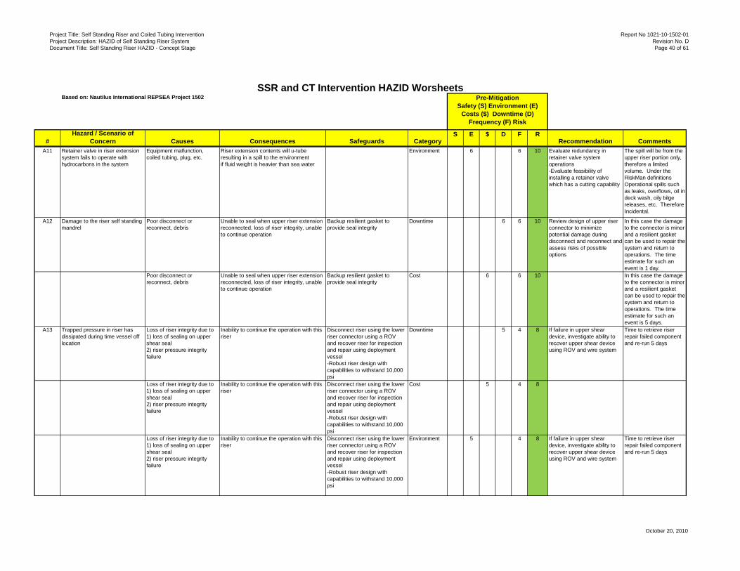
Project Title: Self Standing Riser and Coiled Tubing InterventionProject Description: HAZID of Self Standing Riser SystemDocument Title: Self Standing Riser HAZID - Concept Stage
Report No 1021-10-1502-01Revision No. DPage 40 of 61
October 20, 2010
#Hazard / Scenario of
Concern Causes Consequences Safeguards CategoryS E $ D F R
Recommendation Comments
Based on: Nautilus International REPSEA Project 1502SSR and CT Intervention HAZID Worsheets
Pre-MitigationSafety (S) Environment (E)
Costs ($) Downtime (D) Frequency (F) Risk
A11 Retainer valve in riser extension system fails to operate with hydrocarbons in the system
Equipment malfunction, coiled tubing, plug, etc.
Riser extension contents will u-tube resulting in a spill to the environmentif fluid weight is heavier than sea water
Environment 6 6 10 Evaluate redundancy in retainer valve system operations-Evaluate feasibility of installing a retainer valve which has a cutting capability
The spill will be from the upper riser portion only, therefore a limited volume. Under the RiskMan definitions Operational spills such as leaks, overflows, oil in deck wash, oily bilge releases, etc. Therefore Incidental.
A12 Damage to the riser self standing mandrel
Poor disconnect or reconnect, debris
Unable to seal when upper riser extension reconnected, loss of riser integrity, unable to continue operation
Backup resilient gasket to provide seal integrity
Downtime 6 6 10 Review design of upper riser connector to minimize potential damage during disconnect and reconnect and assess risks of possible options
In this case the damage to the connector is minor and a resilient gasket can be used to repair the system and return to operations. The time estimate for such an event is 1 day.
Poor disconnect or reconnect, debris
Unable to seal when upper riser extension reconnected, loss of riser integrity, unable to continue operation
Backup resilient gasket to provide seal integrity
Cost 6 6 10 In this case the damage to the connector is minor and a resilient gasket can be used to repair the system and return to operations. The time estimate for such an event is 5 days.
A13 Trapped pressure in riser has dissipated during time vessel off location
Loss of riser integrity due to 1) loss of sealing on upper shear seal2) riser pressure integrity failure
Inability to continue the operation with this riser
Disconnect riser using the lower riser connector using a ROV and recover riser for inspection and repair using deployment vessel-Robust riser design with capabilities to withstand 10,000 psi
Downtime 5 4 8 If failure in upper shear device, investigate ability to recover upper shear device using ROV and wire system
Time to retrieve riser repair failed component and re-run 5 days
Loss of riser integrity due to 1) loss of sealing on upper shear seal2) riser pressure integrity failure
Inability to continue the operation with this riser
Disconnect riser using the lower riser connector using a ROV and recover riser for inspection and repair using deployment vessel-Robust riser design with capabilities to withstand 10,000 psi
Cost 5 4 8
Loss of riser integrity due to 1) loss of sealing on upper shear seal2) riser pressure integrity failure
Inability to continue the operation with this riser
Disconnect riser using the lower riser connector using a ROV and recover riser for inspection and repair using deployment vessel-Robust riser design with capabilities to withstand 10,000 psi
Environment 5 4 8 If failure in upper shear device, investigate ability to recover upper shear device using ROV and wire system
Time to retrieve riser repair failed component and re-run 5 days

Project Title: Self Standing Riser and Coiled Tubing InterventionProject Description: HAZID of Self Standing Riser SystemDocument Title: Self Standing Riser HAZID - Concept Stage
Report No 1021-10-1502-01Revision No. DPage 41 of 61
October 20, 2010
#Hazard / Scenario of
Concern Causes Consequences Safeguards CategoryS E $ D F R
Recommendation Comments
Based on: Nautilus International REPSEA Project 1502SSR and CT Intervention HAZID Worsheets
Pre-MitigationSafety (S) Environment (E)
Costs ($) Downtime (D) Frequency (F) Risk
B1 Inadvertent disconnect of upper
riser connector with common umbilical providing power and signal to retainer valve, connector, near surface shear seal system, SSD and subsea tree.
Human error, equipment malfunction
Tree valves and SCSSV close on the coiled tubing.-SSD fails as is
Downtime 1 6 6 Do not configure the riser system umbilical into a common system where single point failure could result in possible well control.
The time to contract a suitable vessel to isolate the well pull the tree and repair the valves is 180 days. This assumes that a MODU or large Intervention vessel such as the Q4000 will be required to pull the tree.
Human error, equipment malfunction
Tree valves and SCSSV close on the coiled tubing.-SSD fails as is
Cost 1 6 6 The time to contract a suitable vessel to isolate the well pull the tree and repair the valves is 180 days. This assumes that a MODU or large Intervention vessel such as the Q4000 will be required to pull the tree.
B2 Inadvertent disconnect of upper riser connector with two umbilicals one providing power and signal to retainer valve, connector, near surface shear seal system, and independent umbilical providing power and signal to SSD and subsea tree.
Human error, equipment malfunction
Temporary loss of control of well until SSD functions-Unknown actuation of uppernear surface seal at this time-Issues associated with operation of coil unit at surface due to inadvertent disconnect, potential damage to coil
Downtime 1 6 6 Review design function of upper shear system to insure well integrity upon disconnect of riser extension connector-Protocols need to be developed for loss of station keeping and inadvertent disconnect of riser-Ensure functions which could result in an advertent disconnect are secured
Time to pull riser due to damage to Upper Shear Seal device and repair the upper shear seal device and re-run is 10 days
Human error, equipment malfunction
Temporary loss of control of well until SSD functions-Unknown actuation of near surface seal at this time-Issues associated with operation of coil unit at surface due to inadvertent disconnect, potential damage to coil
Cost 1 6 6 Time to pull riser due to damage to Upper Shear Seal device and repair the upper shear seal device and re-run is 10 days
Inadvertent Disconnect

Project Title: Self Standing Riser and Coiled Tubing InterventionProject Description: HAZID of Self Standing Riser SystemDocument Title: Self Standing Riser HAZID - Concept Stage
Report No 1021-10-1502-01Revision No. DPage 42 of 61
October 20, 2010
#Hazard / Scenario of
Concern Causes Consequences Safeguards CategoryS E $ D F R
Recommendation Comments
Based on: Nautilus International REPSEA Project 1502SSR and CT Intervention HAZID Worsheets
Pre-MitigationSafety (S) Environment (E)
Costs ($) Downtime (D) Frequency (F) Risk
B3 Inadvertent operation of lower SSD connector
Human error, equipment malfunction
Release of riser at SSD, loss of total well control, riser will propel itself to surface due to buoyancy, potential damage to vessel
Safety 3 6 8 SSD to tree connector to be configured for ROV actuation only.-Ensure that detail reviews are undertaken to tree to SSD connector system for potential failure resulting in disconnect-Examine possible methods for riser retention should inadvertent disconnect occur-Examine potential for interlock from tree to SSD to prevent inadvertent disconnect
The unexpected nature of this event could result in injuries to personnel working on the CT platforms. The worst case would be a lost time injury of one or more personne;
Human error, equipment malfunction
Release of riser at SSD, loss of total well control, riser will propel itself to surface due to buoyancy, potential damage to vessel.Spill due to loss of well control will depend upon the state of the well. If well will not flow naturally then spill will be limited although Coil Tubing could be across the SCSSV and the Tree Valves.
Environment 4 6 9 With Coiled Tubing across the Tree and the SCSSV the well could flow naturally for a considerable period of time. Such an event would be categorised as Major on the Environmental consequence scale.
Human error, equipment malfunction
Release of riser at SSD, loss of total well control, riser will propel itself to surface due to buoyancy, potential damage to vessel.- Riser is still intact but would have to recover the riser back onto the well and fish the coiled tubing from the well and
Downtime 3 6 8 The riser indavertenly disconnecting then recovering back onto the well and recovering any fish in the well approximately 90 days.
Human error, equipment malfunction
Release of riser at SSD, loss of total well control, riser will propel itself to surface due to buoyancy, potential damage to vessel.- Riser is still intact but would have to recover the riser back onto the well and fish the coiled tubing from the well and
Cost 3 6 8 The riser indavertenly disconnecting then recovering back onto the well and recovering any fish in the well approximately 90 days.
Riser Integrity

Project Title: Self Standing Riser and Coiled Tubing InterventionProject Description: HAZID of Self Standing Riser SystemDocument Title: Self Standing Riser HAZID - Concept Stage
Report No 1021-10-1502-01Revision No. DPage 43 of 61
October 20, 2010
#Hazard / Scenario of
Concern Causes Consequences Safeguards CategoryS E $ D F R
Recommendation Comments
Based on: Nautilus International REPSEA Project 1502SSR and CT Intervention HAZID Worsheets
Pre-MitigationSafety (S) Environment (E)
Costs ($) Downtime (D) Frequency (F) Risk
C1 Corrosion Inappropriate use of materials resulting in a galvanic cellor poor paint job
Excessive corrosion on the cathode of the system during extended deployment of riser before actual intervention.- Potential crevice corrosion or for excessive anode depletion- Earth leak in subsea system could result in SSR acting as an extended anode.
Tree system should have corrosion protection.Subsea system earth leakage monitoring system.SSR has anode protection.
Cost 5 6 10 Assess requirements for corrosion protection on riser-Develop corrosion compatibility system for riser
The Subsea Control system earth leakage detection will switch to back up system to minimize the risk.Platform should alert on earth leakage then riser could be pulled by deployment vessel to minimize the risk.No downtime as work would be offline to primary well intervention activity.
C2 Fatigue VIV and surface currents effecting riser which induces cyclical motion [translational and rotational]
Use of fatigue life more rapid than expected.Loss of pressure integrity of the SSR system.Shut in subsea tree and make well safe and recover riser for repair.
Potential for rotating high fatigue areas to low fatigue areas-Design basis criteria for system operation in fatigue conditions- Pressure monitoring of the riser system when coiled tubing operations ongoing.
Downtime 4 5 8 Evaluate system for mitigating fatigue issues, i.e., strakes, fairings, buoyancy elevation and drill string tracking system
Fatigue damage is not a likely failure due to the fact that the riser will be pulled and inspected between operations. If a fatigue failure was to go un-noticed then the failure could be catastrophic with a potential riser collapse and spill to the environment. Assume 10 days to recover the riser and return to previous point in the operation
VIV and surface currents effecting riser which induces cyclical motion [translational and rotational]
Use of fatigue life more rapid than expected.Loss of pressure integrity of the SSR system.Shut in subsea tree and make well safe and recover riser for repair.
Potential for rotating high fatigue areas to low fatigue areas-Design basis criteria for system operation in fatigue conditions- Pressure monitoring of the riser system when coiled tubing operations ongoing.
Cost 4 5 8 Fatigue damage is not a likely failure due to the fact that the riser will be pulled and inspected between operations. If a fatigue failure was to go un-noticed then the failure could be catastrophic with a potential riser collapse and spill to the environment. Assume 120 days to recover the riser and return to previous point in the operation
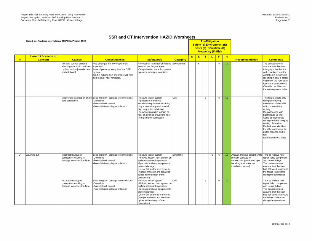
Project Title: Self Standing Riser and Coiled Tubing InterventionProject Description: HAZID of Self Standing Riser SystemDocument Title: Self Standing Riser HAZID - Concept Stage
Report No 1021-10-1502-01Revision No. DPage 44 of 61
October 20, 2010
#Hazard / Scenario of
Concern Causes Consequences Safeguards CategoryS E $ D F R
Recommendation Comments
Based on: Nautilus International REPSEA Project 1502SSR and CT Intervention HAZID Worsheets
Pre-MitigationSafety (S) Environment (E)
Costs ($) Downtime (D) Frequency (F) Risk
VIV and surface currents effecting riser which induces cyclical motion [translational and rotational]
Use of fatigue life more rapid than expected.Loss of pressure integrity of the SSR system.Shut in subsea tree and make well safe and recover riser for repair.
Potential for rotating high fatigue areas to low fatigue areas-Design basis criteria for system operation in fatigue conditions
Environment 6 5 10 The consequences assume that the riser intergrity is lost but the well is isolated and the operation is suspended resulting in only a partial volume of the riser been lost to the environment. Classified as Minor on the consequence index.
Inadvertent backing off of drill pipe connection
Lose integrity - damage to connections-Downtime-Potential well control-Potential riser collapse or launch
Pressure test of system-Application of makeup installation equipment recording torque on makeup and special high torque thread design-Buoyancy provides tension on riser at all times preventing riser from going on connection
Cost 5 6 10 This failure would only take place during installation of the SSR which is an off-line activity.If a connection was badly made up this would be highlighted during the initial integrity testing of the riser. If a leak was identified then the riser would be pulled repaired and re-run.Estimated time 3 days.
C4 Washing out Incorrect makeup of connection resulting in damage to connection face
Lose integrity - damage to connections-Downtime-Potential well control-Potential riser collapse or launch
Pressure test of system-Ability to inspect riser system on surface after each operation-Specialist makeup equipment to prevent damage.-Use of drill as the riser system (multiple make up and break up cylces in the design of the connection)
Downtime 5 6 10 Analyze makeup equipment to prevent damage to connections [dedicated pipe handling equipment on installation vessel]
Time to retrieve riser repair failed component and re-run 5 days.The consequences assume that the riser has not failed totally and the failure is detected during the operations.
Incorrect makeup of connection resulting in damage to connection face
Lose integrity - damage to connections-Downtime-Potential well control-Potential riser collapse or launch
Pressure test of system-Ability to inspect riser system on surface after each operation-Specialist makeup equipment to prevent damage.-Use of drill as the riser system (multiple make up and break up cylces in the design of the connection)
Cost 5 6 10 Time to retrieve riser repair failed component and re-run 5 days.The consequences assume that the riser has not failed totally and the failure is detected during the operations.

Project Title: Self Standing Riser and Coiled Tubing InterventionProject Description: HAZID of Self Standing Riser SystemDocument Title: Self Standing Riser HAZID - Concept Stage
Report No 1021-10-1502-01Revision No. DPage 45 of 61
October 20, 2010
#Hazard / Scenario of
Concern Causes Consequences Safeguards CategoryS E $ D F R
Recommendation Comments
Based on: Nautilus International REPSEA Project 1502SSR and CT Intervention HAZID Worsheets
Pre-MitigationSafety (S) Environment (E)
Costs ($) Downtime (D) Frequency (F) Risk
Lose integrity - damage to connections Pressure test of system-Ability to inspect riser system on surface after each operation-Specialist makeup equipment to prevent damage.-Use of drill as the riser system (multiple make up and break up cylces in the design of the connection)
Environment 5 6 10 The consequences assume that the riser intergrity is lost but the well is isolated and the operation is suspended resulting in only the contents of the riser been lost to the environment. Classified as Minor on the consequence index.
C5 Gouging of riser developing in to a crack
Running downhole tool through riser on coil or higher angle at wellhead interface-Mechanical induced gouge due to operation e.g. mud motor
Lose riser integrity -Downtime
Pressure integrity monitoring of the riser during operation to detect any cracks.- Continuous inspection of riser between jobs.- Data on riser joint position in the string.- Record offset data during operation.- Monitoring of returns for metal debris.
Downtime 2 6 7 Ensure thorough NDT inspection between operations
Gouging of the riser could result in a crack developing resulting in a catastrophic failure of the riser along similar lines to the Fatigue failure. Assume 120 days of downtime to recover the situation.
Running tube through riser on coil or higher angle at wellhead interface-Mechanical induced gouge due to operation of mud motor
Lose integrity -Downtime
Continuous inspection of riser between jobs.- Data on riser joint position in the string.- Record offset data during operation.
Cost 2 6 7 Gouging of the riser could result in a crack developing resulting in a catastrophic failure of the riser along similar lines to the Fatigue failure. Assume 120 days of downtime to recover the situation.
Lose integrity - damage to connections Continuous inspection of riser between jobs.- Data on riser joint position in the string.- Record offset data during operation.
Environment 6 6 10 The consequences assume that the riser intergrity is lost but the well is isolated and the operation is suspended resulting in only the contents of the riser been lost to the environment. Classified as Minor on the consequence index.

Project Title: Self Standing Riser and Coiled Tubing InterventionProject Description: HAZID of Self Standing Riser SystemDocument Title: Self Standing Riser HAZID - Concept Stage
Report No 1021-10-1502-01Revision No. DPage 46 of 61
October 20, 2010
#Hazard / Scenario of
Concern Causes Consequences Safeguards CategoryS E $ D F R
Recommendation Comments
Based on: Nautilus International REPSEA Project 1502SSR and CT Intervention HAZID Worsheets
Pre-MitigationSafety (S) Environment (E)
Costs ($) Downtime (D) Frequency (F) Risk
C6 Erosion Flowing sand through system at high velocities
Lose riser integrity -Downtime
Flow-rate optimization to minimize damage
Downtime 2 6 7 Investigate whether internals of riser need to be coated to prevent damage due to erosion caused by sand, corrosion, etc.
Time to retrieve riser repair failed component and re-run 5 days.The consequences assume that the riser has not failed totally and the failure is detected during the operations.
Flowing sand through system at high velocities
Lose integrity -Downtime
Flow-rate optimization to minimize
Cost 2 6 7 Time to retrieve riser repair failed component and re-run 5 days.The consequences assume that the riser has not failed totally and the failure is detected during the operations.
Lose integrity - lower tensile strength Environment 5 6 10 The consequences assume that the riser intergrity is lost but the well is isolated and the operation is suspended resulting in only the contents of the riser been lost to the environment. Classified as Minor on the consequence index.
D1 Unknown well conditions below shear point [near surface shear seal point]
Well integrity issues Unknown well conditions below upper shear point-Limited well control options following reconnection of riser extension
Downtime 4 6 9 Review specification of upper shear point to allow for monitoring of pressures and ability to circulate-Develop SSR CT intervention well control procedures
Time to bring a well control event back under control is 5 to 10 days
Well integrity issues Unknown well conditions below upper shear point-Limited well control options following reconnection of riser extension
Cost 4 6 9 Time to bring a well control event back under control is 5 to 10 days
D2 Unknown well conditions below shear point [SSD]
Well integrity issues Unknown well conditions below upper shear point-Limited well control options following reconnection of riser extension
SSD has facility for monitoring pressures below the rams-Ability to install circulating hose on spool between rams-Ability to monitor pressures with tree instrumentation (may require ROV actuation of tree valves)
Downtime 4 6 9 Prior to opening of SSD appropriate procedures should be followed to assess well bore conditions below SSD.-Further develop circulating hose and monitoring device specification as project progresses
Time to bring a well control event back under control is 5 to 10 days
Well Control Issues

Project Title: Self Standing Riser and Coiled Tubing InterventionProject Description: HAZID of Self Standing Riser SystemDocument Title: Self Standing Riser HAZID - Concept Stage
Report No 1021-10-1502-01Revision No. DPage 47 of 61
October 20, 2010
#Hazard / Scenario of
Concern Causes Consequences Safeguards CategoryS E $ D F R
Recommendation Comments
Based on: Nautilus International REPSEA Project 1502SSR and CT Intervention HAZID Worsheets
Pre-MitigationSafety (S) Environment (E)
Costs ($) Downtime (D) Frequency (F) Risk
Well integrity issues Unknown well conditions below upper shear point-Limited well control options following reconnection of riser extension
SSD has facility for monitoring pressures below the rams-Ability to install circulating hose on spool between rams-Ability to monitor pressures with tree instrumentation (may require ROV actuation of tree
Cost 4 6 9 Time to bring a well control event back under control is 5 to 10 days
E1 Handling pipe on vessel Vessel motions, Man-handling equipment
Potential for injury to personnel on deck of vessel when handling equipment
Tag lines, Winches, Trained and competent crews, JSA etc.
Safety 4 2 5 Ensure that appropriate pipe handling equipment is used to handle pipe on the installation vessel.
The worst case would be a lost time injury of one or more personnel;
Other Issues
CT Equipment Layout and Operations

Project Title: Self Standing Riser and Coiled Tubing Intervention Report No 1021-10-1502-01 Project Description: HAZID of Self Standing Riser System Revision No. D Document Title: Self Standing Riser HAZID - Concept Stage Page 48 of 61
October 20, 2010
APPENDIX II
HAZID TERMS OF REFERENCE

Project Title: Self Standing Riser and Coiled Tubing Intervention Report No 1021-10-1502-01 Project Description: HAZID of Self Standing Riser System Revision No. D Document Title: Self Standing Riser HAZID - Concept Stage Page 49 of 61
October 20, 2010
SELF STANDING RISER AND CT INTERVENTION HAZID WORKSHOP
Purpose The purpose of the SSR HAZID is to provide a forum for a group of industry experts to review the proposed SSR design with respect to operations associated with CT well intervention and identify hazards and associated risks. The HAZID is not a design or engineering review process. Issues concerning engineering or design changes will be noted as actions to be undertaken outside the HAZID meeting. Sponsor The HAZID sponsor is Mr. Chuck Yemington of Nautilus International on behalf of Project 1502. Scope The Scope of the Self Standing Riser and CT Intervention HAZID is as follows: 1. The load out of the self standing riser components including coiled tubing equipment onto a vessel
capable of deployment at the desired location. 2. The installation of the 6-5/8 inch Self Standing Riser (SSR) at the location. 3. Relocating and testing the assembled SSR. 4. Assembly and wet parking the SSR Riser Extension. 5. Mobilization of the CT Vessel. 6. On-site preparation of the CT vessel and equipment. 7. On-Site intervention activities. 8. Routine and Emergency Disconnect scenarios. Aims The SSR HAZID has the following objectives to review the SSR System design for Health, Safety and Environmental Hazards and Design and Operability issues with specific reference to the following: • Undertake a structured and comprehensive review of the SSR system using a formal Hazard
Identification (HAZID) process to identify and develop specific hazard scenarios associated with the SSR system.
• Provide a complete, clearly stated list of hazard scenarios, which originate from the systems studied that have the potential to affect the safety of the facility including personnel, 3rd party stakeholders, regulators and the environment.
• Assess the risk associated with the individual hazard scenarios. • Provide recommendations in terms of specific design operations or procedural changes or additional
studies to further understanding the identified hazards and reduce the associated risks. • Provide guidance to the management of the SSR project for the purposes of Risk Management as
the project goes forward.

Project Title: Self Standing Riser and Coiled Tubing Intervention Report No 1021-10-1502-01 Project Description: HAZID of Self Standing Riser System Revision No. D Document Title: Self Standing Riser HAZID - Concept Stage Page 50 of 61
October 20, 2010
• Provide assurance that, once all the follow up activities have been verified as satisfactorily completed, all identified hazards and design and operability problems have been eliminated or can be managed to a level that is As Low As Reasonably Practicable (ALARP).
• Provide a complete and comprehensive record of the study teams thinking and conclusions drawn during each of the study sessions in a formal HAZID report.
Objectives The following objectives were agreed with the Nautilus Team members prior to the HAZID: • To identify the high level risks associated with the CT Intervention Riser System, including the
Running of the Free Standing Riser, Mobilization of the vessel with the CT unit rigging up on the well undertaking three operations (P&A, SCSSV replacement, and a Tubing Clean out for wax, asphaltene, scale etc).
• Assess whether the hazard scenarios identified and their associated risk present a level of risk which can be managed to ALARP.
• Provide a list of issues to be studied in the FEED stage of the project which need further analysis or engineering work.
• Identify issues around such matters as ‘Technology Step out’, ‘Design Uncertainty’, and ‘Anomalies’ which could affect the overall project including schedule etc.
Boundaries The study boundaries of the HAZID study are: • The operations associated with the SSR and CT activities as described in the Nautilus International
document ‘Overview of Procedures for Review HAZID Meeting 13-Oct-2010’
The study excludes: • Commercial issues and • Availability of contractors to support offshore operations
Table 1.0 - Location and Timing of the HAZID
Location Timing
The HAZID will be held at the offices of Baker Hughes 17015 Aldine Westfield Road Houston, TX 77073
The HAZID will be held on the 13th October 2010
HAZID Process The following is a short description of the HAZID process including Workshop Sessions and the follow up work.

Project Title: Self Standing Riser and Coiled Tubing Intervention Report No 1021-10-1502-01 Project Description: HAZID of Self Standing Riser System Revision No. D Document Title: Self Standing Riser HAZID - Concept Stage Page 51 of 61
October 20, 2010
IDENTIFY OPERATION BEING REVIEWED
SCENARIO HAZARD
IS IT POSSIBLE IS IT LIKELY?
BRAINSTORM THREATS AND CAUSES
NO
YES
ASSESS
ARE ADDITIONAL SAFEGUARDS REQUIRED?
CONTROLS WHAT CONTROLS OR BARRIERS CONTROL OR RECOVER FROM
THE EFFECT?
YES
RECORD RECOMMEND ADDITIONAL
SAFEGUARDS
NO
Workshop Session • Review the agenda, HAZID purpose, objectives, scope and process to be used • Define risk assessment terms, risk matrix and level of event to be captured. • Deliver presentations to the HAZID participants addressing the scope of the work using the SSR for
CT interventions. • Identify hazards and brainstorm hazard scenarios. • Develop hazard scenarios utilizing HAZID log-sheets. • Identify risk mitigations actions to be transferred to an Action Tracking Register for closure at the
next stage of the project. The HAZID Process

Project Title: Self Standing Riser and Coiled Tubing Intervention Report No 1021-10-1502-01 Project Description: HAZID of Self Standing Riser System Revision No. D Document Title: Self Standing Riser HAZID - Concept Stage Page 52 of 61
October 20, 2010
Post-Workshop • The HAZID Leader will complete and distribute a set of draft findings (HAZID logsheets) from the
HAZID to the workshop participants for input within 3 days of the HAZID workshop. • The HAZID Leader will prepare and issue a draft report to the Sponsor within 7 working days of the
HAZID workshop. • The Sponsor will distribute the report and assign a responsible individual to each action item. • The HAZID Leader will update the draft report with comments within 3 weeks of the HAZID meeting. Deliverables • A HAZID report that outlines the findings and risk reduction options • Risk Matrix Summary showing the various scenarios and their risk ranking • HAZID logsheets. • Appendices (e.g. basic assumptions, risk matrix, attendees list, references, Terms of Reference) • A draft of this report will be reviewed by the risk assessment participants for accuracy before final
report distribution. Roles and Responsibilities The following are a short description of the individual Roles and Responsibilities: Sponsor • Primary responsibility for HAZID and approves HAZID Terms of Reference • Responsible for follow-up and close-out of HAZID recommendations. HAZID Leader • Finalize the Terms of Reference. • Provides HAZID methodology expertise. • Facilitate hazard scenario identification. • Active participation in the HAZID to ensure comprehensive evaluation. • Keep focus, maintain progress against the agenda. • Completes the Draft and the Final report. Team Members • Provide technical expert participation. • Assist in developing hazard scenarios and risk reduction opportunities.
Pre-Read Information Pre-read material to support the workshop comprises: • Terms or Reference – this document. • Nautilus International Overview of Procedures for Review HAZID Meeting. Guideword (Key Word) Information The following are a proposed set of guidewords that will be used to identify hazards associated with the SSR and CT intervention activities.

Project Title: Self Standing Riser and Coiled Tubing Intervention Report No 1021-10-1502-01 Project Description: HAZID of Self Standing Riser System Revision No. D Document Title: Self Standing Riser HAZID - Concept Stage Page 53 of 61
October 20, 2010
Table 2.0 - Proposed Guidewords
Guideword (Key Word) Explanation Met-ocean Issues Loop Current Loop currents affects the riser when deployed Vortex Induced Vibration VIV affects the riser when deployed Seabed currents High seabed currents affect the riser Hurricane abandonment Hurricane is approaching the area of operations Riser Failure Modes External Corrosion External corrosion of the riser Internal Corrosion Internal corrosion on the riser Loss of Surface Tension Failure of Surface Tensioner System Loss of Riser Buoyancy Failure of the Riser Buoyancy System Damage to riser internals Gouging of the riser or wear due to contact on internal surface Loss of Containment Failure of the Riser e.g. connector failure crack propagation Fatigue of the riser Fatigue of the riser due to prolonged exposure Control System or Service Supply Issues Inadvertent Disconnect The Riser inadvertently disconnects from the subsea tree Unable to isolate Control System failure results in failure to isolate the well Loss of Services to Equipment Loss of air or electrical power to equipment from vessel Loss of Communications Loss of communications with Subsea Equipment Communications Failure Failure of Communications on Vessel Handling Issues Deck Space Restrictive deck space on vessel Deck Loading Limited deck loading capacity Lifting equipment Crane capacities, crane operating arcs, Dropped Objects Dropped Object to deck or to subsea Pressure stored Energy Working around pressure and stored energy Vessel motions Working on deck with motions of 300 ft vessel Vessel Hazards Loss of DP Loss of DP Position - Drive Off - Drift Off - Force Off Fire on Vessel Fire or other emergency on vessel Loss of Vessel Stability Loss of the vessel stability while on operations Other Hazards Errant Vessel Errant vessel in close proximity to SSR operation SIMOPs Simultaneous Operations (Production, Construction etc).

Project Title: Self Standing Riser and Coiled Tubing Intervention Report No 1021-10-1502-01 Project Description: HAZID of Self Standing Riser System Revision No. D Document Title: Self Standing Riser HAZID - Concept Stage Page 54 of 61
October 20, 2010
Guideword (Key Word) Explanation Environmental Issues Handling Hydrocarbons Hydrocarbons at surface or hydrocarbon contaminated fluid Spills Spill of chemicals or well fluids Regulatory Issues Changes in Legislation Changes in regulations in Gulf of Mexico Technology and Project Issues New or Un-proven Technology Project using new or unproven technology or technology step outs Design Uncertainty Project has design uncertainties pressures, temperatures fluid types etc
Proposed HAZID Worksheet Format The following is the proposed HAZID Worksheet Format
Key Word
Causes Consequences Risk Category
L C RR Safeguards Action Actionee
Risk Categories – Safety Environmental Project L – Likelihood C – Consequence Severity RR – Risk Ranking

Project Title: Self Standing Riser and Coiled Tubing Intervention Report No 1021-10-1502-01 Project Description: HAZID of Self Standing Riser System Revision No. D Document Title: Self Standing Riser HAZID - Concept Stage Page 55 of 61
October 20, 2010
APPENDIX III
RISK MATRICES

Project Title: Self Standing Riser and Coiled Tubing Intervention Report No 1021-10-1502-01 Project Description: HAZID of Self Standing Riser System Revision No. D Document Title: Self Standing Riser HAZID - Concept Stage Page 56 of 61
October 20, 2010
HES RISK MATRIX

Project Title: Self Standing Riser and Coiled Tubing Intervention Report No 1021-10-1502-01 Project Description: HAZID of Self Standing Riser System Revision No. D Document Title: Self Standing Riser HAZID - Concept Stage Page 57 of 61
October 20, 2010
RELIABILITY AND EFFICIENCY MATRIX

Project Title: Self Standing Riser and Coiled Tubing Intervention Report No 1021-10-1502-01 Project Description: HAZID of Self Standing Riser System Revision No. D Document Title: Self Standing Riser HAZID - Concept Stage Page 58 of 61
October 20, 2010
APPENDIX IV
TYPICAL CONSEQUENCE SCENARIOS

Project Title: Self Standing Riser and Coiled Tubing Intervention Report No 1021-10-1502-01 Project Description: HAZID of Self Standing Riser System Revision No. D Document Title: Self Standing Riser HAZID - Concept Stage Page 59 of 61
October 20, 2010
The following table provides estimated data on the likely consequence costs for various hazard events identified by the HAZID team. The purpose of these is to provide a base line for the cost and downtime estimates for the risk ranking exercise. Should any of these costs be further refined as the project progresses then this table could be used to estimate the new costs. Day rate for repair is based on the installation vessel alone for problems during SSR installation, the intervention vessel alone for problems that the intervention vessel can fix, and both vessels in the unique case of Seafloor Shutoff Device failure during down-hole work. It is assumed that all personnel and equipment transfers for the smaller vessels will be made at the host platform and that regularly scheduled supply boats and helicopters will be used for transfers between the host platform and the shore base. Day rates (including fuel, lube, and personnel) are based on $150,000 per day for installation vessel, $200,000 for intervention vessel, $250,000 per day for a large construction vessel such as the Aker Sub Sea or Deep Sea, $350,000 for larger intervention vessel such as the Q4000, and $450,000 day for a MODU. These rates are subject to market conditions.
ACTIVITY SPREAD COSTS $K/DAY
COSTS DOWNTIME
Time to pull a damaged riser repair joint and re-run 5 days
150 $0.75MM 5 Days
Time to pull SSD repair and re-run, 10 to 12 days
350 $3.50MM 10 Days
Time to pull riser extension due to damage to Upper Shear Seal device and repair the upper shear seal device and re-run is 3 days
200 $0.60MM 3 Days
Repair to the Upper Riser disconnect point due to failure to disconnect in a clean manner. Time to pull the riser extension, repair the connector and re-run and test the system 3 days
200 $0.60MM 3 Days
Any fishing operation could take up to 30 + days 200 $6.00MM 30 Days Time to bring a well control event back under control is 5 to 10 days assuming no other problems
200 $2.00MM 10 Days
Intervention vessel disconnects from the riser and there is slight damage to the connector requiring the use of a back up resilient seal to allow the operations to continue. Estimated time to restore operations is 5 days
200 $1.00MM 5 Days
Intervention vessel disconnects with hydrocarbons in the riser, when reconnect hydrate plug in the system resulting in more complex operation to restore the system to safe state. Estimated time 25 days
200 $4.00MM 20 Days

Project Title: Self Standing Riser and Coiled Tubing Intervention Report No 1021-10-1502-01 Project Description: HAZID of Self Standing Riser System Revision No. D Document Title: Self Standing Riser HAZID - Concept Stage Page 60 of 61
October 20, 2010
ACTIVITY SPREAD COSTS
$K/DAY COSTS DOWNTIME
If tree is damaged and one USV valve is operable but the tree has to be pulled to repair the tree Master or Swab valves is 90 days broken down as 60 days contract vessel and sail to location, 20 days to pull tree and repair and re-run. Assumes SCSSV is still operable.
450 Assumes a rig or
large intervention vessel such as
Q4000 is required to pull tree
$9.00MM 20 Days
If tree is damaged and USV valve is inoperable the time to procure and run a new tree is >60 days to pull tree repair completion. This scenario also includes the damage to the SCSSV which is required to be repaired.
$450 Assumes a rig or
large intervention vessel such as
Q4000 is required to pull tree
$27MM 60 Days
Failure to disconnect from the Upper Disconnect point will result in a collapse of the riser and damage to the well and subsea architecture. Assume 120 days to to re-establish the operation back on the well.
$450 $54MM 120 Days
Inadvertent disconnect from the well will result in extensive time to recover the operation. Estimated time to locate riser back on the well fish the Coiled Tubing from the well 30 days.
$300K $9MM 30
RISER INTEGRITY ISSUES Corrosion damage to the riser is considered to be a slow process which should be able to be prevented. Any corrosion failure is likely to start as a small leak and loss of pressure integrity resulting loss of the riser contents and not likely to result in a major downtime or costs. Components are installed for short duration and inspected before reinstallation.
350
Fatigue damage is not a likely failure due to the fact that the riser will be pulled and inspected between operations. If a fatigue failure was to go un-noticed then the failure could be catastrophic with a potential riser collapse and spill to the environment. See above for riser collapse
$350 Assumes a rig or
large intervention vessel such as
Q4000 is required to recover the operations
$42MM 120 Days

Project Title: Self Standing Riser and Coiled Tubing Intervention Report No 1021-10-1502-01 Project Description: HAZID of Self Standing Riser System Revision No. D Document Title: Self Standing Riser HAZID - Concept Stage Page 61 of 61
October 20, 2010
ACTIVITY SPREAD COSTS
$K/DAY COSTS DOWNTIME
Incorrect Make up The worst case scenario is that the riser collapses on to the subsea architecture following the failure. The scenario assumes that the SSD has functioned cut the coil and isolated the well. The downtime is due to the dropped riser and the associated damage to the well and close by subsea architecture. Downtime is estimated to be 120 days to inspect the subsea equipment, pull the riser and re-establish the vessel on the well.
$350 Assumes a rig or
large intervention vessel such as
Q4000 is required to recover the operations
$42MM 120 Days
Wash Out See Corrosion above for details of time lost etc.
Gouging See Fatigue failure Erosion See corrosion above for details of time lost