tablet format - vwcup-files.track360.com
TRANSCRIPT

Self Study Program 881213
Air Conditioning and Heat Pump in MEB VehiclesTablet Format

Volkswagen Group of America, LLC Volkswagen Academy Published in U.S.A. 2/2021
Course Number SSP 881213
©2021 Volkswagen Group of America, LLC.
All rights reserved. All information contained in this manual is based on the latest information available at the time of publishing and is subject to the copyright and other intellectual property rights of Volkswagen Group of America, LLC., its affiliated companies and its licensors. All rights are reserved to make changes at any time without notice. No part of this document may be reproduced, stored in a retrieval system, or transmitted in any form or by any means, electronic, mechanical, photocopying, recording or otherwise, nor may these materials be modified or re posted to other sites without the prior expressed written permission of the publisher.
All requests for permission to copy and redistribute information should be referred to Volkswagen Group of America, LLC.
Always check Technical Bulletins and the latest electronic repair information for information that may supersede any information included in this booklet.
Trademarks: All brand names and product names used in this manual are trade names, service marks, trademarks, or registered trademarks; and are the property of their respective owners.

Introduction . . . . . . . . . . . . . . . . . . . . . . . . . . . . . . . . . . . . . . . . . . . . . . . . . . . . . . . . . . . . . . . . . 1
ID Climatronic . . . . . . . . . . . . . . . . . . . . . . . . . . . . . . . . . . . . . . . . . . . . . . . . . . . . . . . . . . . . . . . 3
Heater and Air Conditioning Unit R1234yf/R744 . . . . . . . . . . . . . . . . . . . . . . . . . . . . . . . . 12
Basic Refrigerant Circuit with Battery Cooling . . . . . . . . . . . . . . . . . . . . . . . . . . . . . . . . . . . 26
Heat Pump with Refrigerant R744 . . . . . . . . . . . . . . . . . . . . . . . . . . . . . . . . . . . . . . . . . . . . 34
Air Conditioning System Operation . . . . . . . . . . . . . . . . . . . . . . . . . . . . . . . . . . . . . . . . . . . . 48
Heat Pump Mode . . . . . . . . . . . . . . . . . . . . . . . . . . . . . . . . . . . . . . . . . . . . . . . . . . . . . . . . . . . 52
Table of Contents

1
Introduction
Air Conditioning and Heat Pump in MEB Vehicles
Overview
The ID.4, as well as all future models in the Modular Electric Drive (MEB) matrix, will be available with two different air conditioning systems.
• The basic version is a single-zone Climatronic system.
• 2-zone Climatronic is also available as standard equipment on some vehicle lines, or as an option.
Both of the above systems use R1234yf refrigerant in the refrigerant circuit. Also, they have a “chiller” function that is used to cool the battery through a heat exchanger.
An available heat pump system uses carbon dioxide (CO2 / R744) as a refrigerant. Canadian vehicles will have this option at launch. However, this will not be initially be available in the USA.
The heat pump system is always equipped with battery cooling. The system uses the waste heat from the battery, drive motor, power electronics and charging device as a heat source.
Base + battery cooling
R1234yf as refrigerant
Heat pump
Circuit with battery cooling
R744 CO2 as refrigerant
1-zone or 2-zone
Climatronic
Circuit with battery cooling
2-zone Climatronic
only
Optional heat pump with R744 for range
optimization

2
Introduction
CO2 as Refrigerant in the Heat Pump
CO2 Properties
The chemical formula for carbon dioxide is CO2. It’s in the air all around us and does not harm the earth’s ozone layer. When used as a refrigerant, it is referred to R744.
A/C systems using CO2 operate at about 10 times the pressure of previous refrigerants. The refrigerant circuit must be more robust due to the higher pressure, and also because CO2 molecules are smaller than the molecules of the previous refrigerants.
Each refrigerant has a different Global Warming Potential (GWP). The GWP is calculated in terms of the warming potential of one kilogram of a gas over a period (normally 100 years) relative to one kilogram of CO². A lower GWP refrigerant equals a higher emission credit for the manufacturers fleet.
Refrigerant R-12
• GWP = 10,720
• Contains chlorine, which depletes the ozone layer
• Remains in Earth’s atmosphere for over 100 years
• Damaging to ozone layer
Refrigerant R-134a
• GWP = 1,430
• Does not contain chlorine
• Retained in Earth’s atmosphere for 13 years
• While not damaging to the ozone layer, it is a greenhouse gas
Refrigerant R-1234yf
• GWP = 4
• Retained in Earth’s atmosphere for 11 days
Refrigerant R-744 (CO2)
• GWP = 1
• Retained in Earths atmosphere for >200 years, yet is a naturally occurring gas

3
ID.4 Climatronic
Operation
Climatronic in the ID.4 can be operated either by using the screen or using voice control. The system is easy to activate by saying the wake-up phrase “Hello ID” or by pressing the Voice button on the steering wheel. The vehicle will respond by saying, for example, “Yes?” or “What would you like to do?” and reacts intuitively to voice commands such as “I feel cold.”
New digital microphones not only perfect voice recognition and voice quality when making phone calls, but also pinpoint if the driver or the passenger are speaking. This is important for 2-zone Climatronic systems. Support from online recognition makes commands more flexible and allows them to be made when speaking naturally.
The statement “I feel cold/warm” lowers or raises the preset temperature by 1.8°F (1°C), except when the pre-selected temperature was set to Low or High. In this case, the temperature setting switches to 71.6°F (22°C).
All functions found in the Classic and Smart A/C menu, along with the defrost function, can be activated using voice control.
All functions of both Climatronic systems can be operated using the MIB touchscreen. To operate specific functions in the A/C menu quickly, there is a direct start button in the middle of the dash panel.
Some features previously associated with Climatronic, such as the defrost and heated rear window functions, are integrated into the light and visibility cluster to the left of the steering column.

4
ID.4 Climatronic
Operation
Light and Visibility Cluster – EX59 Illumination Control Head
Voice Control – “Hello ID...” – the Wake-up Phrase for Activation.
Direct Access Button – EX22 Switch Module in Instrument Panel, Center
"Hello, ID...""I feel cold"

5
ID.4 Climatronic
Snowflake symbol as a warning for slippery conditions.
Classic Climate Menu (1- or 2-zone Climatronic)
Air Care Menu
Smart Climate Menu/Enhanced Automatic Functions
Operation
The touchscreen Classic Climate menu has familiar A/C buttons and functions.
If the Climatronic system is off, it can be activated using the ON/OFF function or using the defrost button in the light and visibility cluster.
The temperature values are reference values for the temperature in the vehicle interior. The actual temperatures, especially at the vent outlets, may differ from these reference values.
The seat heating temperature regulation can be turned on and adjusted by means of a “two-finger tap” using the temperature selection touch buttons on the right and left under the screen.
Slippery conditions warning
At outside temperatures colder than approximately 39°F (4°C), a snowflake symbol appears. This symbol lights up until the outside temperature rises above 43°F (6°C).
The function is switched on or off in the “Air Care” menu.

6
ID.4 Climatronic
Operation
Only one of the listed functions can be active at any one time in the “Smart Climate” menu.
Fresh air:
• Volume of air increases (without changing the air distribution)
• Vent temperature decreases
• Switch over from (automatic or manual) air recirculation mode to fresh air mode. Manual activation of air recirculation mode when the “Fresh Air” function is active will end the function.
Quick heating:
• Maximum heating output by means of a PTC air heater in the A/C unit with a 6 kW output
Quick cooling:
• Maximum cooling output of the A/C system
Clear View (defog windows):
• Volume of air flowing towards the windshield increases
• The vent temperature is adjusted as needed
• Air drying increases by lowering the evaporator temperature
Warm feet:
• Volume of air flowing into the footwell increases
• Vent temperature increases
Warm hands:
• Volume of air flowing towards occupants increases
• Vent temperature increases
Cool feet:
• Volume of air flowing into the footwell increases
• Vent temperature decreases

7
ID.4 Climatronic
Operation – R744 ID .Cockpit Messages
A/C system error messages are shown in the ID.Cockpit.
Air conditioning defective – find a service center
This error message can have different causes:
• Fault in the CO2 sensor that is detected for more than 10 seconds
• Fresh air and air recirculation flap fault
• Blower fault
Ventilate vehicle via window:
CO2 sensor reports increased CO2 concentration between 1.5% and 2.5% volume in the interior.
Ventilate urgently using window or exit vehicle:
CO2 sensor reports increased CO2 concentration over 2.5% volume in the vehicle interior.
Vehicle overheated! Air conditioning required:
Either ICAS1 or ICAS2 (“In Car Application Server” – currently two high-performance control units) is too hot. The A/C is activated to cool the passenger compartment.
Approximately 80% of the vehicle’s computing power is bundled withing the ICAS control modules. The remaining control modules have been more or less downgraded to output stages with data bus connections.
As a gas, CO2 is about 1.5 times heavier than ambient air and collects in lower areas such as inspection pits. It can remain there for a long time if there is little air movement.
• Carbon dioxide is not regarded as toxic. However, higher concentrations (3–5%) can cause headaches, dizziness, light-headedness, drowsiness and nausea
• Concentrations above 5% can lead to loss of coordination skills and unconsciousness
• Concentrations above 8% can lead to respiratory arrest and death
Problem/Meaning Icon Color Signal tone
Vehicle Overheated Air Conditioning Necessary
White No Signal Tone
Air Conditioning Defective Find a Service Center
Yellow 1x - long
Ventilate Vehicle via Window Yellow 1x - long
Ventialate Vehicle Urgently via Window or Exit
Red3x - short with repetition
60MPH
Air Conditioning Defective Find a Service Center
50 miles 60 MPH

8
ID.4 Climatronic
Component Locations - J979 Heating and Air Conditioning Control Module
The vehicle interior temperature sensor is located between the center vent and the storage compartment in the center console. A LIN-Bus system transmits data to the control module.
The Heating and Air Conditioning Control Module J979 is located on the right side of the A/C unit under the dash panel.
J979
G1090 Vehicle Interior Temperature Sensor

9
ID.4 Climatronic
Component Locations - J979 Heating and Air Conditioning Control Module .
The control module is accessed by removing the glove box. The control module can be unclipped from the bracket using a removal wedge, then pulled out.
J979
Locking Tab

10
ID.4 Climatronic
Component Locations - G260 A/C Humidity Sensor and G397 Rain/Light Recognition Sensor
The G260 and the G397 are combined in one component and located behind the mirror base trim in the windshield area. The sun level for the air conditioning system is detected with light sensor G397. There is no longer a dedicated sunlight sensor on the dash panel.
The air from the windshield area reaches the humidity sender by the air intake on the mirror trim. The humidity is used to control automatic air recirculation mode.
A LIN-Bus system is used to transmit data to the onboard supply control module. The information is then sent to the J979 Heating and Air Conditioning Control Module through the data bus system.
Air intakeTrim
G397
G260
The mirror base design of the North American ID.4 is configured differently than the one pictured, but all components will be included.

11
ID.4 Climatronic
Air Distribution in the Dash Panel
The air distribution for the defrost function is integrated into the dash panel using noise-optimized channels. The defrost function air is directed around in the front and rear areas. The air duct on the dash panel is the same for 1-zone and 2-zone Climatronic.
Windshield Defrost Function Vent
Defrost Function Air Duct System
Quarter and Side Window Defrost Function
Right Occupant Vent
Left Occupant Vent
Rear Left Footwell Vent Rear Right Footwell Vent
Center Vent

12
Heater and Air Conditioning Unit R1234yf / R744
VX47 Defroster DoorG935 Exterior Air Quality and Humidity Sensor
VX96 Fresh and Air Recirculation Door
J126 Fresh Air Blower Control Module
G308 Evaporator Temperature Sensor
ZX17 High-Voltage Heater (PTC)
VX34 Left Front Control Temperature Door
G261 Left Footwell Vent Temperature Sensor
VX93 Left Front Air Distribution Door
2-part Basic Concept
The new design of the heater and A/C unit in the MEB has two parts – the intake box in the front of the vehicle and the distribution box in the interior. This optimizes interior space. Another benefit of the two part design allows for the same HVAC unit to be used in both right-hand and left-hand drive vehicles.
Component descriptions are on the next page.

13
Heater and Air Conditioning Unit R1234yf / R744
2-part Basic Concept
Components on this page are displayed in the graphic on the previous page.
The VX34 Front Left Temperature Flap:
• Contains the potentiometer for G220 Left Temperature Control Door Motor Position Sensor
• Contains the V158 Left Temperature Control Door Motor
• Has a flap movement range of 180°
The VX47 Defroster Door:
• Contains the G135 Defroster Door Motor Position Sensor
• Contains the V107 Defroster Door Motor
• Has a door movement range of 120°
The VX93 Left Front Air Distribution Door:
• Contains the G1105 Left Front Air Distribution Door Motor Position Sensor
• Contains the V706 Left Front Air Distribution Door Motor
• Has a door movement range of 340°
The VX96 Fresh and Air Recirculation Door:
• Contains the G644 Fresh Air/Recirculating Air/Back Pressure Door Motor Position Sensor
• Contains the V425 Fresh Air/Recirculating Air/Back Pressure Door Motor
• Has a door movement range of 340°
Notes:
• The J126 Fresh Air Blower Control Module contains the fresh air blower V2, but this is no longer listed separately in the wiring diagrams.
• The J848 High-Voltage Heater (PTC) Control Module is integrated into the ZX17 High-Voltage Heater (PTC).

14
Heater and Air Conditioning Unit R1234yf / R744
2-part Basic Concept/Seals
Component descriptions are on the next page.
VX94 Right Front Air Distribution Door
VX35 Right Front Temperature Control Door
G262 Right Footwell Vent Temperature Sensor
Air Intake Cowling
Air Recirculation Flap
Air Intake Box
Fresh Air Intake
Air Recirculation Intake

15
Heater and Air Conditioning Unit R1234yf / R744
2-part Basic Concept/Seals
Components on this page are displayed in the graphic on the previous page.
The air intake cowl forms the connection between the air intake box (exterior) and the HVAC unit (interior) and is attached to the bulkhead.
In air recirculation mode, the vehicle interior air is drawn through the air intake cowling and the air recirculation flap into the air intake box. It is then guided through the filter and blown back into the HVAC unit and distributed via flaps.
The VX94 Right Front Air Distribution Door:
• Contains the G1106 Right Front Air Distribution Door Motor Position Sensor
• Contains the V707 Right Front Air Distribution Door Motor
• Has a door movement range of 340°
The VX35 Right Front Temperature Control Door:
• Contains the G221 Right Temperature Control Door Motor Position Sensor
• Contains the V159 Right Temperature Control Door Motor
• Has a door movement range of 180°

16
Heater and Air Conditioning Unit R1234yf / R744
R744 Cooling/Heating Components
Only the PTC high-voltage heater and the evaporator with a thermal expansion valve are installed in the R1234yf-equipped HVAC unit for Climatronic (not shown in the image).
The heating gas cooler R744 is placed in front of the PTC high-voltage heater in the same HVAC unit for the Climatronic with heat pump. This means that there are four screw connections on the bulkhead between the vehicle front end and the HVAC unit in the vehicle interior. This area is only visible for repair once the intake box in the vehicle front end has been removed.
All four pipes lead to the front right valve unit assembly on the longitudinal member.
The outer sheathing of some hoses may have a type of “seal” applied to it. The manufacturer occasionally checks pipes for leaks between the inner and outer layers, and then closes the test hole again with a “seal”.
Illustration shown using the “Reheat” function.
Condensation DrainHeating Gas Cooler Feed (HP)
ZX17 High-Voltage Heater (PTC)
Heating Gas Cooler R744
Evaporator
Evaporator Return (LP)
Heating Gas Cooler (HP) Return
Evaporator Feed (LP)

17
Heater and Air Conditioning Unit R1234yf / R744
ZX17 High-Voltage Heater (PTC)
System description is on the next page.
J848 with Power Electronics
Low-voltage Connection
Radiator for Power Electronics
4 Heating Circuit Elements
Potential Equalization
High-voltage Connection

18
Heater and Air Conditioning Unit R1234yf / R744
ZX17 High - Voltage Heater (PTC)
The high-voltage heater (PTC) ZX17 consists of:
• J848 High-Voltage Heater (PTC) Control Module
• Z115 High-Voltage Heater (PTC)
The same high-voltage heater is used for the 1-zone and 2-zone Climatronic systems. The A/C control module sends the Climatronic coding bit across the LIN-Bus to the high-voltage heater control module.
The PTC heater has an operational range between 0 to 6 kW. It is activated progressively by the A/C control module in steps of 1%. The maximum heating output of 6 kW is only provided on very cold days and when the battery management control module permits the power to do so.
In vehicles with a heat pump, the high-voltage heater functions as a supplementary heater and bridges the slow reaction of the heat pump in the different operating modes. For example, in the event of a…
• restart after ignition on
• or if the customer adjusts the desired temperature upwards in order to feel a fast reaction
• or if a repeated request is made for windshield defogging
It is normal to have a slight smell when the ZX17 High Voltage Heater is operating, similar to a hair dryer on a high heat setting.

19
Heater and Air Conditioning Unit R1234yf / R744
G929 Vehicle Interior Carbon Dioxide Concentration Sensor
Component Location Design
The three connection contacts are assigned to terminals 30/31 and to LIN-Bus 2 in the middle. The information goes from the sensor to the A/C control module and then to the ICAS 1 (In Car Application Server 1)
The G929 is clipped into the lower area of the HVAC unit and can be removed with a removal wedge (for example 3409) after removing the tunnel cover.
G929
3-pin connector
Printed circuit with CO2 sensor
Mounting (yellow)

20
Heater and Air Conditioning Unit R1234yf / R744
G929 Vehicle Interior Carbon Dioxide Concentration Sensor
How it Works
Air Intake
Air Intake
Infrared Radiation SourceDetector
Filter
The lower the intensity of radiation at the sensor, the higher the CO2 concentration in the interior.
The sensor uses the NDIR (non-dispersive infrared) procedure.
Infrared radiation is irradiated in a measuring channel by the IR source in the direction of filter and detector. Each gas molecule has the property of absorbing a specific wavelength. CO2 has a wavelength of 4.3 microns (4.3 µm). The optical filter makes the measured signals clearer for the detector, so that it can measure the radiation intensity of the specific wavelengths more precisely. The lower the intensity of radiation at the sensor, the higher the CO2 concentration in the interior.

21
Heater and Air Conditioning Unit R1234yf / R744
Cooling/Heating Air Distribution
This is a cross-section of the HVAC unit.
Air intake is shown on the left of the diagram. The air comes from the intake box in the front of the vehicle as fresh air (or recirculation air) and flows through the evaporator. If necessary, the air is cooled and dried here, and then mixed with warm air in a mixer chamber and distributed.
In heating mode, the air is heated up to the requested temperature either by the high-voltage heater, the heating gas cooler R744 or by both components in combination mode.
Mixing Chamber
Cooling Heating
Heating Gas Cooler R744
ZX17 High-Voltage Heater (PTC)
Evaporator

22
Heater and Air Conditioning Unit R1234yf / R744
Air Intake Box
The fresh air blower consists of the V2 Motor and the J126 Fresh Air Blower Control Module (dark blue). The fresh air (or recirculation air) is drawn in from below by the blower through the respective intake, through the interior filter, and then blown into the distribution box in the vehicle interior. The entire air intake box is located at the front of the vehicle (the area formerly known as the engine compartment), reducing noise in the vehicle interior.
4-pin electrical connection:
• Pin A1 Terminal 31 leads to the Ground point at the front left in the wheel housing
• Pin A2 not assigned
• Pin A3 Terminal 30 via fuse SC1 (30 A) from fuse holder C
• Pin A4 LIN-Bus to the HVAC unit
Fresh Air Intake Air Recirculation
Intake
Air path into the Distribution Box

23
Heater and Air Conditioning Unit R1234yf / R744
Interior Filter
The air filter can be replaced by removing a cover under the hood. The filter mounting in the air intake box has the capability for two filters. Only a single Air Care filter with allergen coating is used in Canada and the USA. There is an additional slot that is used for different filters in other countries.
Allergen Filter
Cover

24
Heater and Air Conditioning Unit R1234yf / R744
Heater and Air Conditioning Systems in the Modular Electric Drive Matrix
Roller Blind Radiator
System description is on the next page.
End Strip with Cable Connection
Cable with Left Cable Shell
Drive Motor for Roller Blind Radiator
Idler Rollers
Cable with Right Cable Shell
Roller Blind Rolled up on the Fabric Rod
25
Heater and Air Conditioning Unit R1234yf / R744
Heater and Air Conditioning Systems in the Modular Electric Drive Matrix
Roller Blind Radiator
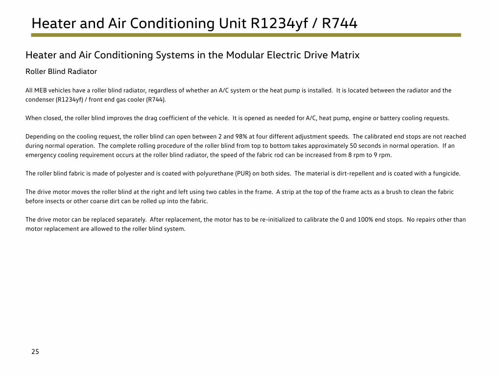
All MEB vehicles have a roller blind radiator, regardless of whether an A/C system or the heat pump is installed. It is located between the radiator and the condenser (R1234yf) / front end gas cooler (R744).
When closed, the roller blind improves the drag coefficient of the vehicle. It is opened as needed for A/C, heat pump, engine or battery cooling requests.
Depending on the cooling request, the roller blind can open between 2 and 98% at four different adjustment speeds. The calibrated end stops are not reached during normal operation. The complete rolling procedure of the roller blind from top to bottom takes approximately 50 seconds in normal operation. If an emergency cooling requirement occurs at the roller blind radiator, the speed of the fabric rod can be increased from 8 rpm to 9 rpm.
The roller blind fabric is made of polyester and is coated with polyurethane (PUR) on both sides. The material is dirt-repellent and is coated with a fungicide.
The drive motor moves the roller blind at the right and left using two cables in the frame. A strip at the top of the frame acts as a brush to clean the fabric before insects or other coarse dirt can be rolled up into the fabric.
The drive motor can be replaced separately. After replacement, the motor has to be re-initialized to calibrate the 0 and 100% end stops. No repairs other than motor replacement are allowed to the roller blind system.

26
Basic Refrigerant Circuit with Battery Cooling
Overview – Basic Equipment with R1234yf as Refrigerant
Condenser
G805 G395N636
N541
Desiccant Cartridge
Heat Exchanger for High-Voltage Battery
Evaporator with Thermal Expansion Valve
ZX17
VX81
• VX81 A/C Compressor
– V470 Electrical A/C Compressor
– J842 A/C Compressor Control Module
• Condenser with desiccant cartridge
• Evaporator with thermal expansion valve
• Heat exchanger for high-voltage battery
• N636 Refrigerant Expansion Valve 1
• N541 Heater and A/C Unit Refrigerant Shut-Off Valve
• G805 Refrigerant Circuit Pressure Sensor
• G395 A/C Pressure/Temperature Sensor
• ZX17 High-Voltage Heater (PTC)
• J848 High-Voltage Heater (PTC) Control Module
The shut-off valve opens and closes the flow of refrigerant into the evaporator. This allows for battery cooling even without A/C operation for the vehicle interior.
The electric expansion valve controls the cooling requirement for the heat exchanger for the HV battery (chiller).

27
Basic Refrigerant Circuit with Battery Cooling
VX81 A/C Compressor with R1234yf
The electrical A/C compressor is located at the front right in the engine compartment. This reduces the compressor noise transmitted into the vehicle interior.
The compressor is a spiral or scroll compressor. The eccentric movement of the rotating spirals compresses the refrigerant continuously and moves it towards the center. It is discharged there under high pressure. The compressor speed determines the amount of coolant pumped.
After replacing the compressor, the scan tool must be used to perform the A/C compressor calibration and initial start-up of the compressor.
Scroll Compressor
High-pressure Pipe
Low-pressure PipeHigh-voltage Connection
Low-voltage Connection
High-pressure Safety Valve
V470 Electrical A/C Compressor
J842 A/C Compressor Control Module
28
Basic Refrigerant Circuit with Battery Cooling
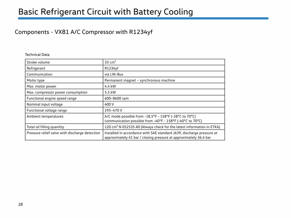
Components - VX81 A/C Compressor with R1234yf
Stroke volume 33 cm³
Refrigerant R1234yf
Communication via LIN-Bus
Motor type Permanent magnet – synchronous machine
Max. motor power 4.4 kW
Max. compressor power consumption 5.5 kW
Functional engine speed range 600–8600 rpm
Nominal input voltage 400 V
Functional voltage range 195–470 V
Ambient temperatures A/C mode possible from -18.5°F - 158°F (-28°C to 70°C)communication possible from -40°F - 158°F (-40°C to 70°C)
Total oil filling quantity 120 cm³ N 052535 A0 (Always check for the latest information in ETKA)
Pressure relief valve with discharge detection Installed in accordance with SAE standard J639, discharge pressure at approximately 41 bar / closing pressure at approximately 36.4 bar
Technical Data
29
Basic Refrigerant Circuit with Battery Cooling
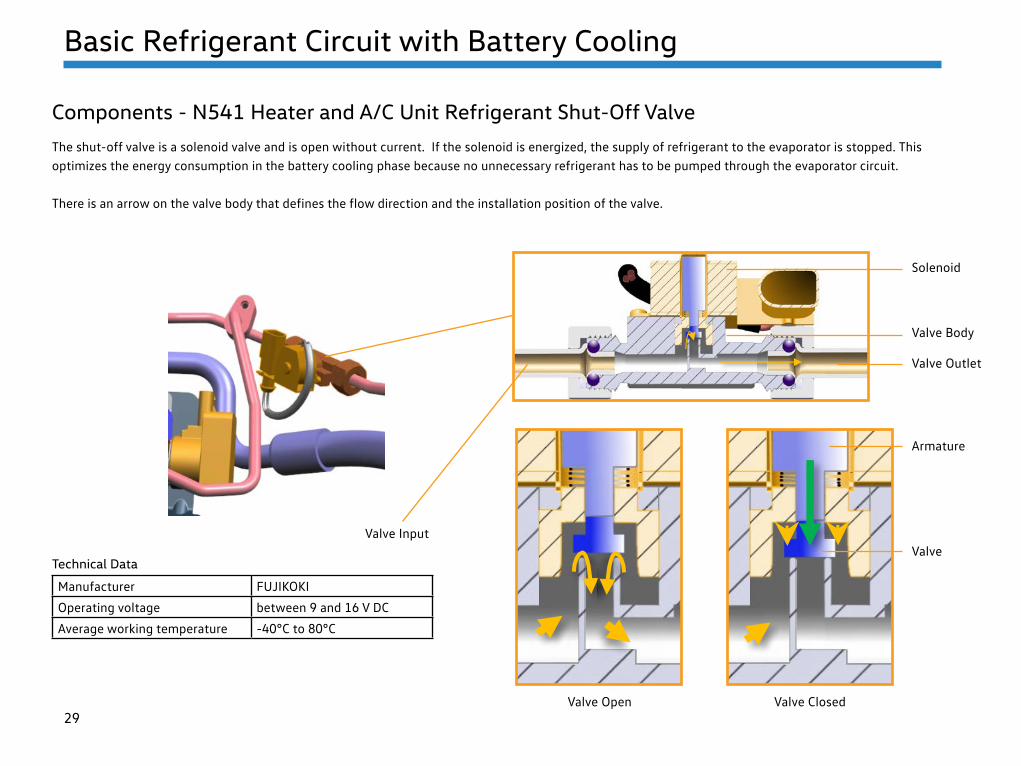
Components - N541 Heater and A/C Unit Refrigerant Shut-Off Valve
The shut-off valve is a solenoid valve and is open without current. If the solenoid is energized, the supply of refrigerant to the evaporator is stopped. This optimizes the energy consumption in the battery cooling phase because no unnecessary refrigerant has to be pumped through the evaporator circuit.
There is an arrow on the valve body that defines the flow direction and the installation position of the valve.
Manufacturer FUJIKOKI
Operating voltage between 9 and 16 V DC
Average working temperature -40°C to 80°C
Technical Data
Valve Open Valve Closed
Valve Input
Solenoid
Valve Body
Valve Outlet
Armature
Valve

30
Basic Refrigerant Circuit with Battery Cooling
Components - Heat Exchanger for High-Voltage (HV) Battery
A heat exchanger for the HV battery, better known as a “chiller,” is a component in the ID.4. It is located in the right front of the vehicle. Heat exchange takes place between the refrigerant circuit and the coolant circuit of the HV components.
In combination with the N636 Refrigerant Expansion Valve 1, this component can be used to actively cool the high-voltage components such as the battery, electric drive motor, power electronics, etc.
Battery cooling is necessary in different operating modes.
• While charging, the chiller is activated at a battery temperature > 86°F (30°C)
• When the vehicle is moving, the chiller is activated at a battery temperature of > 95°F (35°C)
Coolant Connections Refrigerant Connections
Heat Exchanger (chiller)
N636
31
Basic Refrigerant Circuit with Battery Cooling
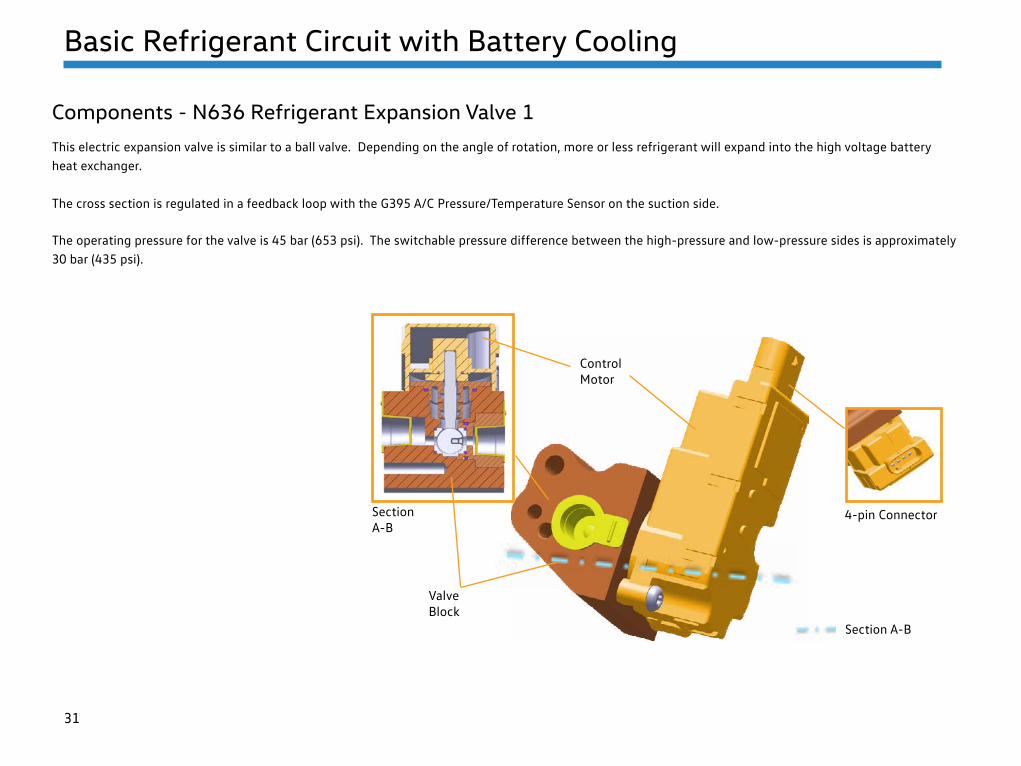
Components - N636 Refrigerant Expansion Valve 1
This electric expansion valve is similar to a ball valve. Depending on the angle of rotation, more or less refrigerant will expand into the high voltage battery heat exchanger.
The cross section is regulated in a feedback loop with the G395 A/C Pressure/Temperature Sensor on the suction side.
Section A-B
4-pin Connector
Valve Block
Section A-B
Control Motor
The operating pressure for the valve is 45 bar (653 psi). The switchable pressure difference between the high-pressure and low-pressure sides is approximately 30 bar (435 psi).

32
Basic Refrigerant Circuit with Battery Cooling
Components - G805 Refrigerant Circuit Pressure Sensor
The refrigerant pressure sensor is similar to other A/C sensors.
Positive (3) and negative (1) are connected on the 3-pin connector. In the middle (2), has a LIN-Bus wire that is connected to the HVAC Control Module J979.
The sensor can be removed and installed using the special tool – socket T40284. There is a Schrader valve in the pipe connection, so that the sensor can be replaced without having to extract the refrigerant.
3-pin Connector
Screw Connection to the Refrigerant Line
Printed Circuit with Pressure Sensor
33
Basic Refrigerant Circuit with Battery Cooling
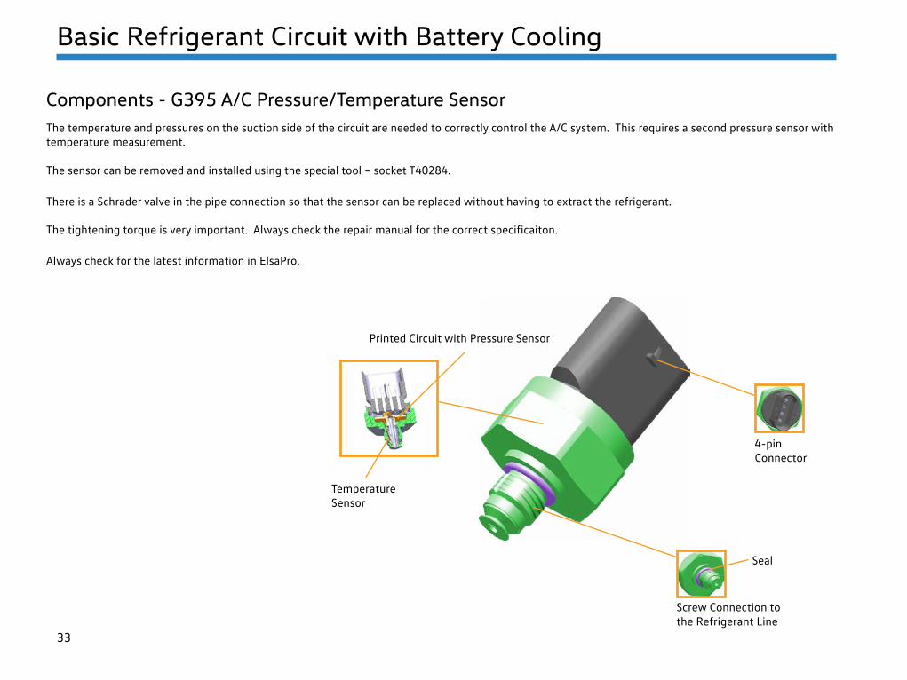
Components - G395 A/C Pressure/Temperature SensorThe temperature and pressures on the suction side of the circuit are needed to correctly control the A/C system. This requires a second pressure sensor with temperature measurement.
The sensor can be removed and installed using the special tool – socket T40284.
There is a Schrader valve in the pipe connection so that the sensor can be replaced without having to extract the refrigerant. The tightening torque is very important. Always check the repair manual for the correct specificaiton. Always check for the latest information in ElsaPro.
Printed Circuit with Pressure Sensor
4-pin Connector
Seal
Temperature Sensor
Screw Connection to the Refrigerant Line

34
Heat Pump with Refrigerant R744
Overview
The following parts are for the heat pump refrigerant circuit:
• VX81 A/C Compressor
– V470 Electrical A/C Compressor
– J842 A/C Compressor Control Module
• A/C gas cooler in the front
• Evaporator
• Heating gas cooler in the A/C unit
• Heat exchanger for HV battery
• ZX17 High-Voltage Heater (PTC)
• J848 High-Voltage Heater (PTC) Control Module
• Heat pump valve unit assembly
The valve unit assembly consists of (blue circle):
• 4 double valve blocks with Electric Expansion Valves (EXV) and/or Electrical Shut-off Valves (ASV)
• Various pipes
• The heat exchanger for the high-voltage battery
• The accumulator/dryer, which also works as an Internal Heat Exchanger (IWT).
R744 Service Connections
Heat Pump Valve Unit Assembly
ZX17 High-Voltage Heater (PTC)
Heating Gas Cooler
Evaporator
AC Gas Cooler(without dryer)
Heat Exchanger for High-voltage Battery
The heat pump system is monitored by five pressure and temperature sensors. Three of them are colored green in the image.
After refilling the refrigerant circuit, use the scan tool to reset the counter for CO2 refrigerant loss!

35
Heat Pump with Refrigerant R744
Scroll Compressor
Low-pressure Pipe
High-pressure Pipe Low-voltage Connection
High-voltage Connection
J842 A/C Compressor Control Module
V470 Electrical A/C Compressor
High-pressure Safety Valve
VX81 A/C Compressor with R744
The electrical A/C compressor is located at the front right of the engine compartment. This reduces the compressor noise transmitted into the vehicle interior. In addition, a type of silencer is installed inside as noise insulation. The compressor housing is reinforced, minimizing vibrations.

36
Heat Pump with Refrigerant R744
VX81 A/C Compressor with R744
The R1234yf and R744 compressors have the same basic design. However, the R744 compressor has:
• Significantly greater wall thicknesses
• The displacement is just 5.3 cm³ instead of 27 cm³
• The connection geometry for the refrigerant lines has been adapted to suit the special R744 connection technology with axial sealing block connectors. All connections in the R744 circuit are axial sealing block-type.
The refrigerant circuits for A/C mode and the heat pump mode are designed so that the compressor cannot intake liquid refrigerant. The accumulator/dryer (IWT) on the suction side upstream of the compressor ensures that the liquid is separated and that only gaseous refrigerant with a defined vapor content (~90%) enters the compressor.
The operating pressure is regulated using:
• Pressure and temperature sensors in the refrigerant circuit
• Air temperature sensors downstream of the heat exchangers
• Temperature sensors in the vehicle interior
The software in the A/C Control Module uses this to calculate a target speed for the compressor, then send this information to the compressor electronics.
At an outside temperature of 68°F (20°C) , the system has a stationary pressure of approximately 57 bar (826 psi). The maximum pressure on the low-pressure side is 90 bar (1305 psi).
The system pressures on the high-pressure side depend on the operating mode. Unlike R1234yf, the high pressure can be regulated externally (speed and expansion valve position) to operate the heat pump with the greatest efficiency.
After replacing the compressor, the scan tool must be used to perform the calibration functions and for the initial compressor run.

37
Heat Pump with Refrigerant R744
VX81 A/C Compressor with R744
Stroke volume 5.3 cm³
Refrigerant R744
Communication via LIN-Bus
Motor type Permanent magnet – synchronous machine
Max. motor power 4.4 kW
Max. compressor power consumption 5.5 kW
Functional engine speed range 600–8600 rpm
Nominal input voltage 400 V
Functional voltage range 195–470 V
Ambient temperatures A/C mode possible from -18.5°F - 158°F (-28°C to 70°C)communication possible from -40°F - 158°F (-40°C to 70°C)
Total oil filling quantity 200 cm³ G 065 535 M2 (Always check for the latest information in ETKA)
Pressure relief valve with discharge detection Installed in accordance with SAE standard J639, discharge pressure at approximately 160 bar, closing pressure at approximately 140 bar
Technical Data

38
Heat Pump with Refrigerant R744
Valve Unit Assembly
The valve unit assembly has:
• Four double valve blocks with Electric Expansion Valves (EXV) and/or Electrical Shut-off Valves (ASV)
• Various pipes
• The heat exchanger for the high-voltage battery
• Pressure and temperature sensors
• The accumulator/dryer, which also functions as an internal heat exchanger
ASV3
ASV1
ASV2 ASV4
ASV5
EXV3EXV2
EXV1
High-pressure Lines (red) –All Other Lines are Suction Pressure Lines
Accumulator/dryer, Internal Heat Exchanger
Heat Exchanger for High-voltage Battery
Key:
EXV1 = N636 Refrigerant Expansion Valve 1
EXV2 = N637 Refrigerant Expansion Valve 2
EXV3 = N638 Refrigerant Expansion Valve 3
ASV1 = N696 Refrigerant Shut-Off Valve 1
ASV2 = N640 Refrigerant Shut-Off Valve 2
ASV3 = N641 Refrigerant Shut-Off Valve 3
ASV4 = N642 Refrigerant Shut-Off Valve 4
ASV5 = N643 Refrigerant Shut-Off Valve 5

39
Heat Pump with Refrigerant R744
Design and Function of the Shut-off Valve and Electric Expansion Valve
All shut-off valves and expansion valves look the same. However, there is an internal difference between the two.
• The shut-off valves have a cylindrical valve needle. This means they can only be in one of two states: open or closed.
• The electric expansion valves have a conical valve needle. The further the valve needle moves out of the valve seat, the greater the cross-section in the expansion chamber.
The sealing plug is inserted after drilling the valve block during manufacturing, and serves no function when servicing the refrigerant system. Some double valve blocks have an high-pressure safety valve on the opposite side.
How it works:
The stepper motor turns the anchor and spindle in the valve. The level of the valve needle is adjusted by the rotating spindle on its inside thread.
Section A-B
Section A-BPressure Connection
Stepper Motor
Armature
Spindle
Valve Needle
Valve Seal

40
Heat Pump with Refrigerant R744
Design and Function of the Shut-off Valve and Electric Expansion Valve
EXV OpenASV Closed ASV Open EXV Closed EXV Expansion
The example below shows the different operating states of the valves

41
Heat Pump with Refrigerant R744
The high-pressure safety valve on the high-pressure side opens at a pressure of approximately 160 bar (up to max. 170 bar) and closes again when the pressure has decreased (at approximately 150 bar).
The high-pressure safety valve on the low-pressure side opens at a pressure of approximately 120 bar (up to max. 130 bar) and closes again when the pressure has decreased (at approximately 110 bar). Not all of the refrigerant will be discharged.
To ensure that the high-pressure safety valves are not mixed up, they have different thread sizes. Both are left-hand threads.
• On the high-pressure side – M12 x 1 mm
• On the low-pressure side – M14 x 1 mm
The protective film protects the high-pressure safety valve from dirt and moisture. If the protective film is damaged, the high-pressure safety valve must be replaced.
High-pressure Safety Valve
For Evaporator
Protective Film
High-pressure Safety Valves
There are three high-pressure safety valves in the heat pump system:
1. At the compressor on the high-pressure side
2. For the evaporator on the valve block on the low-pressure side
3. For the accumulator/dryer, also on a valve block on the low-pressure side
The 2nd valve on the evaporator valve block is needed because the evaporator is also used for heating in heat pump mode. This requires high pressure. The high-pressure safety valve protects the evaporator from overpressure if regulation does not work properly or if a valve jams. If there is overpressure, the location of the safety valve protects against CO2 leakage into the vehicle interior.
42
Heat Pump with Refrigerant R744
Pressure and Temperature Sensors G395 and G826 to 829
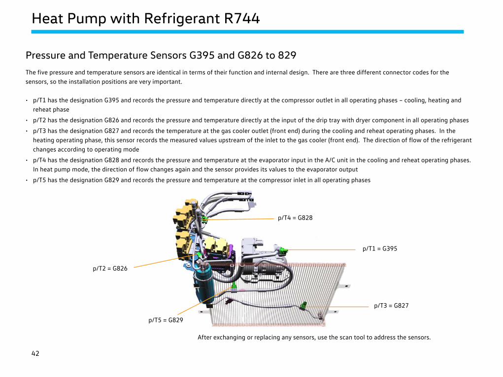
The five pressure and temperature sensors are identical in terms of their function and internal design. There are three different connector codes for the sensors, so the installation positions are very important.
• p/T1 has the designation G395 and records the pressure and temperature directly at the compressor outlet in all operating phases – cooling, heating and reheat phase
• p/T2 has the designation G826 and records the pressure and temperature directly at the input of the drip tray with dryer component in all operating phases
• p/T3 has the designation G827 and records the temperature at the gas cooler outlet (front end) during the cooling and reheat operating phases. In the heating operating phase, this sensor records the measured values upstream of the inlet to the gas cooler (front end). The direction of flow of the refrigerant changes according to operating mode
• p/T4 has the designation G828 and records the pressure and temperature at the evaporator input in the A/C unit in the cooling and reheat operating phases. In heat pump mode, the direction of flow changes again and the sensor provides its values to the evaporator output
• p/T5 has the designation G829 and records the pressure and temperature at the compressor inlet in all operating phases
p/T2 = G826
p/T4 = G828
p/T1 = G395
p/T3 = G827
p/T5 = G829
After exchanging or replacing any sensors, use the scan tool to address the sensors.

43
Heat Pump with Refrigerant R744
Pressure and Temperature Sensors G395 and G826 to 829
The sensors for pressure and temperature are screwed into the refrigerant circuit. Because of the design of the sensor, the connection is not equipped with a Schrader valve. In order for these pressure and temperature sensors to be replaced in the event of failure, the refrigerant circuit must be evacuated.
The silicone disc and seal have various tasks:
• If needed, the silicone disc protects the bolted connection against dirt, etc.
• Sealing the refrigerant circuit
Operating voltage 9.0 to 16V
Temperature measuring range - 40°C to 180°C with a resolution of 0.1°C
Pressure measuring range 0–170 bar with a resolution of 0.05 bar
Data transmission LIN bus 2.0
Technical Data
Printed Circuit with Pressure Sensor
Temperature Sensor
Seal
Silicone Disc
Screw Connection to
the Refrigerant Line
3-pin connector

44
Heat Pump with Refrigerant R744
Accumulator/dryer and Internal Heat Exchanger
The internal heat exchanger runs around the accumulator through the component in a type of pipe coil. The accumulator is made up of the intake manifold with oil bore, the desiccant bag and the “gas supply pipe.” The desiccant bag binds the residual moisture in the system. If the refrigerant circuit has been open for an uncertain period of time, the accumulator/dryer must be replaced.
Always reference the Repair Manual service procedures.
Internal Heat Exchanger IWT
Input/output of Internal Heat Exchanger
Input/output of Internal Heat Exchanger
Filter
Input of Accumulator/Dryer
Output of Accumulator/Dryer
Drip Tray
Gas Supply Pipe
Intake Manifold
Desiccant Bag
Oil Borehole

45
Heat Pump with Refrigerant R744
HANON VisCO²nnect Screw Connection Overview
The HANON VisCO²nnect sealing system works on aluminium and stainless steel pipes and is robust and durable. According to the manufacturer, it can be adapted to all system components and is a metal-tight seal system that protects against contamination.
Note: Always reference the Repair Manual service procedures.
• Always replace securing bolts
• The tigntening torque is very important
• Do not use lubricant
• No tools should be used to remove the captive lock and sealing washer
• Always replace the captive lock and sealing washer
• Check the sealing surface for damage and contamination
• Seals are made of metal (with a special coating) and are only used with R744 refrigerant
• With some screw connections, a special tool must be used as a counter support
Securing Bolt
Refrigerant Line Block
Sealing Washer
Captive Lock
Centering Pin
Housing

46
Heat Pump with Refrigerant R744
Metallic Corrugated Tube for Hot Gas Lines
The flexible hose line structure comes in two versions.
The single hose line has refrigerant and refrigerant oil seals and a resistant interior layer (example: the low-pressure hose). This is covered by the fabric jacket, which makes the hose resistant to pressure. Then there is the part visible to us – the outer layer.
The structure of the hose lines on the high-pressure side is different. Due to the high thermal load caused by the hot gas, there is also a metal-plated corrugated tube inside these hose lines.
These hoses have a limited bending radius and are not allowed to be kinked or twisted.
Outer Layer Inner Layer
Metallic Corrugated Tube
Pressure Absorber Fabric Jacket

47
Heat Pump with Refrigerant R744
Switching Matrix for the Shut-off Valves and Electric Expansion Valves
During the cooling phase, the heat pump operates like a normal A/C system and cools the vehicle interior using the evaporator and/or the high-voltage battery via the “chiller.” In the reheat phase, the incoming fresh air is first cooled to dry it and then heated as needed.
In the heating phase, the heat pump functions solely in heating mode with the PTC air, increasing the range when the vehicle is moving. The compression heat generated by the compressor is discharged directly to the incoming cold fresh air in the A/C unit. In water mode, the temperature of the HV area is regulated accordingly by the “chiller.”
The following graphics show the individual operating phases.
ValvesCooling the
vehicle interiorVehicle interior +
battery Battery only Reheat phase Air heat pump Air / water Water heat pump
ASV1 Closed Closed Closed Open Closed Closed Closed
ASV2 Open Open Open Closed Closed Closed Closed
ASV3 Closed Closed Closed Open Open Open Open
ASV4 Open Open Closed Open Closed Closed Closed
ASV5 Closed Closed Closed Closed Open Open Closed
EXV1 Closed Closed Closed Closed X X X
EXV2 X X X X X X Closed
EXV3 Closed X X Closed Closed X X
Operating Phase: Cooling Operating Phase: Heating
Key:
ASV = Shut Off Valve
EXV = Electric Expansion Valve
X = Expansion Valve is Open to a Width that Depends on the Pressure and Temperature Values

48
Air Conditioning System Operation
Cooling the Vehicle Interior
The simplest operation is when the refrigerant circuit is cooling the vehicle interior.
In the scroll compressor, the gaseous refrigerant is compressed and directed through Shut-off Valve 2 (ASV2) at high pressure and a high temperature into the A/C gas cooler in the front. This is where an energy exchange takes place with the ambient air flowing through, provided that the radiator roller blind is open.
From there, the refrigerant flows through the pipe coil in the internal heat exchanger to Electric Expansion Valve 2 (EXV2) and expands in the evaporator. The incoming interior air is now conditioned efficiently and distributed in the vehicle interior.
The refrigerant is now drawn back into the compressor at low pressure and at a corresponding temperature through Shut-off Valve 4 (ASV4) and the accumulator/dryer.
Key:
ASV = Shut Off Valve
EXV = Electric Expansion Valve
p/T = Pressure and Temperature Sensor
HP = High-Pressure Service Connection
LP = Low-Pressure Service Connection
ASV2
ASV3
ASV5
ASV1ASV4
p/T 1 p/T 5
p/T 2
p/T 3
p/T 4
HP
LP
EXV1
EXV2
EXV3
Summer
= Valve Active

49
Air Conditioning System Operation
Cooling the Vehicle Interior and Battery
If necessary, the “vehicle interior cooling” operating phase can be enhanced with “battery cooling.”
Based on the “vehicle interior cooling” description, the expanded refrigerant can be split after Electric Expansion Valve 2 (EXV2). One part flows into the evaporator of the A/C unit and the other part expands in the heat exchanger for high-voltage battery (chiller) through Active Electric Expansion Valve 3 (EXV3). This is where the energy exchange takes place for the HV battery coolant circuit. The refrigerant is also drawn in as a gas from the chiller by the accumulator/dryer.
Key:
ASV = Shut Off Valve
EXV = Electric Expansion Valve
p/T = Pressure and Temperature Sensor
HP = High-Pressure Service Connection
LP = Low-Pressure Service Connection
ASV2
ASV3
ASV5
ASV1ASV4
p/T 1 p/T 5
p/T 2
p/T 3
p/T 4
HP
LP
EXV1
EXV2
EXV3
Summer
= Valve Active

50
Air Conditioning System Operation
Battery Cooling
In the “battery cooling only” phase, the refrigerant flows through the Expansion Valves 2 and 3 to create an energy exchange in the HV battery heat exchanger (chiller). The evaporator in the A/C unit is passive because Shut-off Valve 4 (ASV4) is closed and stops the refrigerant flow.
Everything else has already been described on the previous pages.
The “battery cooling only” operating phase can also be activated when the HV battery is charging and greater than 86°F (30°C).
When driving, the battery is cooled actively when the temperature is above 95°F (35°C).
Key:
ASV = Shut Off Valve
EXV = Electric Expansion Valve
p/T = Pressure and Temperature Sensor
HP = High-Pressure Service Connection
LP = Low-Pressure Service Connection
ASV2
ASV3
ASV5
ASV1ASV4
p/T 1 p/T 5
p/T 2
p/T 3
p/T 4
HP
LP
EXV1
EXV2
EXV3
Summer
= Valve Active

51
Air Conditioning System Operation
Key:
ASV = Shut Off Valve
EXV = Electric Expansion Valve
p/T = Pressure and Temperature Sensor
HP = High-Pressure Service Connection
LP = Low-Pressure Service Connection
ASV2
ASV3
ASV5
ASV1ASV4
p/T 1 p/T 5
p/T 2
p/T 3
p/T 4
HP
LP
EXV1
EXV2
EXV3
Summer
Reheat Phase
In the reheat phase, the incoming air is cooled and dried in the vehicle interior. Next, the temperature of this air is adjusted to the requested interior temperature. This is performed without the support of the PTC air heater.
Since the Shut-off Valve 2 (ASV2) is closed during this operating phase and the Shut-off Valve 3 (ASV3) is open, the compressed hot refrigerant is directed to the gas cooler in the A/C unit. Here, the dry air is heated.
From there, the hot refrigerant flows through Shut-off Valve 1 (ASV1) into the gas cooler at the front of the vehicle. Energy is exchanged with the oncoming air. The refrigerant is now directed through the internal heat exchanger to Electric Expansion Valve 2 (EXV2), where it expands and enters the evaporator in the A/C unit. Now, interior air is cooled and dried.
From here, the compressor draws the refrigerant through the Shut-off Valve 4 (ASV4) and the drip tray with dryer.
This operating phase is used in situations such as a fogging windshield or if the incoming fresh air has extremely high humidity.
= Valve Active

52
Heat Pump Mode
Key:
ASV = Shut Off Valve
EXV = Electric Expansion Valve
p/T = Pressure and Temperature Sensor
HP = High-Pressure Service Connection
LP = Low-Pressure Service Connection
ASV2
ASV3
ASV5
ASV1ASV4
p/T 1 p/T 5
p/T 2
p/T 3
p/T 4
HP
LP
EXV1
EXV2
EXV3
Air Heat Pump
In the heat pump operating phase, the initial heating phase is slightly sluggish, so support from the PTC air heater is needed. There is not yet enough heat in the battery and drive motor water circuit.
The compressor directs the hot refrigerant gas into the gas cooler in the A/C unit through an open Shut-off Valve 3 (ASV3) - the same as the “reheat phase.” This heats the interior air.
The refrigerant gas is directed through an active Electric Expansion Valve 1 (EXV1) and a closed Shut-off Valve 4 (ASV4) into the evaporator to Electric Expansion Valve 2 (EXV2). This detour increases the efficiency of the system, as a second energy exchange takes place with the evaporator in the A/C unit.
The suction side to the compressor starts here. The refrigerant flows through the internal heat exchanger (without effect). This time, it is opposite of the flow direction we have seen so far, through the gas cooler in the front of the vehicle.
Shut-off Valves 1 and 2 are closed. Shut-off Valve 5 (ASV5) is open. This allows the refrigerant to be pulled in by the compressor through the Accumulator/dryer. This completes the circuit.
Winter
= Valve Active

53
Heat Pump Mode
Key:
ASV = Shut Off Valve
EXV = Electric Expansion Valve
p/T = Pressure and Temperature Sensor
HP = High-Pressure Service Connection
LP = Low-Pressure Service Connection
Air/Water Heat Pump
In the air/water heat pump operating phase, Electric Expansion Valve 3 (EXV3) becomes active and part of the refrigerant expands in the heat exchanger for high-voltage battery (chiller). This is where the energy exchange takes place between the refrigerant of the heat pump and the coolant of the high-voltage battery and the drive motor.
The refrigerant is also drawn in from the chiller by the compressor through the accumulator/dryer.
This operating phase is sort of a mixed operating phase and is used until the high-voltage battery and drive motor have sufficiently heated up the water circuit.
ASV2
ASV3
ASV5
ASV1ASV4
p/T 1 p/T 5
p/T 2
p/T 3
p/T 4
HP
LP
EXV1
EXV2
EXV3
Winter
= Valve Active

54
Heat Pump Mode
Key:
ASV = Shut Off Valve
EXV = Electric Expansion Valve
p/T = Pressure and Temperature Sensor
HP = High-Pressure Service Connection
LP = Low-Pressure Service Connection
Winter Heat Pump
In the water heat pump operating phase, unlike the other two heat pump operating phases, Electric Expansion Valve 2 (EXV2) is closed.
All of the refrigerant flows through Electric Expansion Valve 3 (EXV3) and expands in the heat exchanger for high-voltage battery (chiller).
From here, the refrigerant is pulled by the compressor through the drip tray with dryer.
During this operating phase, the coolant of the HV battery and drive motor is actively cooled with the entire refrigerant flow.
ASV2
ASV3
ASV5
ASV1ASV4
p/T 1 p/T 5
p/T 2
p/T 3
p/T 4
HP
LP
EXV1
EXV2
EXV3
= Valve Active
Winter

Volkswagen Group of America2200 Ferdinand Porsche DriveHerndon, VA 20171February 2021