mechanical requirements—table 1
TRANSCRIPT
16
AST
M A
193
AST
M A
320
TEN
SILE
STRE
NG
TH
MIN
. KSI
(MPA
)
YIEL
D
STRE
NG
TH
MIN
. KSI
(MPA
)
ELO
NG
ATI
ON
2"
(50m
m)
MIN
. %
RED
UCT
ION
OF
ARE
A M
IN.
%
HA
RDN
ESS
MA
XIM
UM
G
RAD
E SI
ZE
B7
2-1
/2”
&
un
de
r 1
10
0 (
59
3)
12
5 (
86
0)
10
5 (
72
5)
16
5
0
32
1 H
B
(35
HR
C)
ove
r 2
-1/2
”
to 4
” 1
10
0 (
59
3)
11
5 (
79
0)
95
(6
55
) 1
6
50
3
21
HB
(35
HR
C)
B7M
No
te 1
2-1
/2”
&
un
de
r 1
15
0 (
62
0)
10
0 (
69
0)
80
(5
50
) 1
8
50
2
35
HB
(99
HR
B)
ove
r 2
-1/2
”
to 4
” 1
15
0 (
62
0)
10
0 (
69
0)
80
(5
50
) 1
8
50
2
35
HB
(99
HR
B)
MIN
IMU
M
TEM
PERI
NG
TEM
P.
°F (°
C)
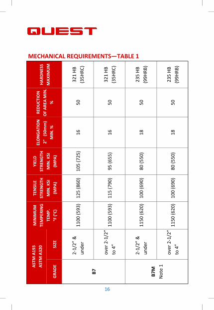
MECHANICAL REQUIREMENTS—TABLE 1

17
AST
M A
193
AST
M A
320
MIN
IMU
M
TEM
PERI
NG
TEM
P.
°F (°
C)
TEN
SILE
STRE
NG
TH
MIN
. KSI
(MPA
)
YIEL
D
STRE
NG
TH
MIN
. KSI
(MPA
)
ELO
NG
ATI
ON
2"
(50m
m)
MIN
. %
RED
UCT
ION
OF
ARE
A M
IN.
%
HA
RDN
ESS
MA
XIM
UM
G
RAD
E SI
ZE
L7
2-1
/2"
&
un
de
r
Qu
en
che
d
an
d
Te
mp
ere
d
11
00
(5
93
)
12
5 (
86
0)
10
5 (
72
5)
16
50
-
L7M
No
te 4
2-1
/2"
&
un
de
r 1
00
(6
90
) 8
0 (
55
0)
18
5
0
23
5 H
B
(99
HR
B)
Qu
en
che
d
an
d
Te
mp
ere
d
11
50
(6
20
)
MECHANICAL REQUIREMENTS—TABLE 2
18
AST
M A
193
AST
M A
320
MIN
IMU
M
TEM
PERI
NG
TEM
P.
°F (°
C)
TEN
SILE
STRE
NG
TH
MIN
. KSI
(MPA
)
YIEL
D
STRE
NG
TH
MIN
. KSI
(MPA
)
ELO
NG
ATI
ON
2"
(50m
m)
MIN
. %
RED
UCT
ION
OF
ARE
A M
IN.
%
HA
RDN
ESS
MA
XIM
UM
G
RAD
E SI
ZE
B8
Clas
s 1
No
te 2
, 3
All
Dia
me
ters
7
5 (
51
5)
30
(2
05
) 3
0
50
2
23
HB
(96
HR
B)
B8
Clas
s 2
No
te 2
3/4
” &
un
de
r
Ca
rbid
e
So
lu$
on
Tre
ate
d
&
Str
ain
Ha
rde
ne
d
12
5 (
86
0)
10
0 (
69
0)
12
3
5
32
1 H
B
(35
HR
C)
ove
r 3
/4”
to 1
”
11
5 (
79
0)
80
(5
50
) 1
5
35
ove
r 1
” to
1-1
/4”
10
5 (
72
5)
65
(4
50
) 2
0
35
ove
r 1
-1/4
”
to 1
-1/2
" 1
00
(6
90
) 5
0 (
34
5)
28
4
5
Ca
rbid
e
So
lu$
on
Tre
ate
d
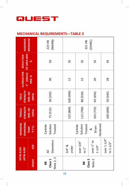
MECHANICAL REQUIREMENTS—TABLE 3

19
AST
M A
193
AST
M A
320
MIN
IMU
M
TEM
PERI
NG
TEM
P.
°F (°
C)
TEN
SILE
STRE
NG
TH
MIN
. KSI
(MPA
)
YIEL
D
STRE
NG
TH
MIN
. KSI
(MPA
)
ELO
NG
ATI
ON
2"
(50m
m)
MIN
. %
RED
UCT
ION
OF
ARE
A M
IN.
%
HA
RDN
ESS
MA
XIM
UM
G
RAD
E SI
ZE
B8M
Clas
s 1
No
te 2
, 3
All
Dia
me
ters
7
5 (
51
5)
30
(2
05
) 3
0
50
2
23
HB
(96
HR
B)
B8M
Clas
s 2
No
te 2
3/4
” &
un
de
r
Ca
rbid
e
So
lu$
on
Tre
ate
d
&
Str
ain
Ha
rde
ne
d
11
0 (
76
0)
95
(6
55
) 1
5
45
32
1 H
B
(35
HR
C)
ove
r 3
/4”
to 1
”
10
0 (
69
0)
80
(5
50
) 2
0
45
ove
r 1
” to
1-1
/4”
95
(6
55
) 6
5 (
45
0)
25
4
5
ove
r 1
-
1/4
” to
1-
1/2
"
90
(6
20
) 5
0 (
34
5)
30
4
5
Ca
rbid
e
So
lu$
on
Tre
ate
d
MECHANICAL REQUIREMENTS—TABLE 4

20
ASTM A-194 MINIMUM ROCKWELL
ASME SA-194 TEMPERING BRINELL HARNDESS
GRADE CLASS AND SIZE TEMP °F (°C) HARDNESS C SCALE B SCALE
2H Up to and
including 1-1/2" 850 (455) 248 - 327 24 - 35
Over 1-1/2" 212 - 327 35 max.
2HM All Sizes 1150 (620) 159 - 235 84 to 99
L7M All Sizes 1150 (620) 159 - 235 84 to 99
7L All Sizes 1100 (595) 248 - 327 24 - 35
B8 & B8M All Sizes 126 - 300 32 max 60 min
95 min.
* In order to meet the tensile requirements, the hardness shall be no
less than 200 HB or 93 HRB .
MECHANICAL REQUIREMENTS—TABLE 5

21
ASTM A320 | A320M MINIMUM AVERAGE
TEST IMPACT VALUE FOR
GRADE TEMP. °F (°C) EACH SET OF 3 SAMPLES
10 x 10 x 50mm
K. - lbs. (Joules)
L7 -150 (-101) 20 (27)
L7M -100 (-73) 20 (27)
L43 -150 (-101) 20 (27)
Impact Energy Absorp�on Requirements
Bol$ng for Low-Temperature Service
MECHANICAL REQUIREMENTS—TABLE 6

22
Iden
�fic
a�on
Spec
ifica
�on
M
ater
ial
Nom
inal
Siz
e M
echa
nica
l Pro
per�
es
Gra
de M
ark
Rang
e (in
.) Pr
oof
Load
(p
si)
Yiel
d St
reng
th
Min
(p
si)
Har
dnes
s
Min
M
ax
A
ST
M A
19
3
AIS
I 4
14
0,
41
42
, O
R
41
05
Qu
en
che
d
an
d
Te
mp
ere
d
1/4
to
2-1
/2
--
10
5,0
00
1
25
,00
0
--
32
1 H
B o
r
35
HR
C
G
rad
e B
7
Ove
r 2
-1/2
to
4
--
95
,00
0
11
5,0
00
B7
Ove
r 4
to
7
--
75
,00
0
10
0,0
00
A
ST
M A
19
3
1/4
to
4
--
80
,00
0
10
0,0
00
--
23
5 H
B o
r
99
HR
C
B7
M
GR
AD
E B
7M
O
ver
4 t
o 7
--
7
5,0
00
1
00
,00
0
23
5 B
HN
or
99
HR
B
A
ST
M A
32
0
AIS
I 4
14
0,
41
42
, O
R
41
05
Qu
en
che
d
an
d
Te
mp
ere
d
1/4
to
2-1
/2
--
10
5,0
00
1
25
,00
0
--
L7
Gra
de
L7
--
A
ST
M A
32
0
--
23
5 H
B o
r
99
HR
B
L7M
G
rad
e L
7M
1
/4 t
o 2
-1/2
--
8
0,0
00
1
00
,00
0
Tens
ile
Stre
ngth
M
in
(psi
) FASTENER IDENTIFICATION MARKINGS
L7M
L7
B7M
B7

23
Iden
�fic
a�on
Spec
ifica
�on
M
ater
ial
Nom
inal
Siz
e M
echa
nica
l Pro
per�
es
Gra
de M
ark
Rang
e (in
.) Pr
oof
Load
(psi
)
Yiel
d St
reng
th
Min
(p
si)
Har
dnes
s
Min
M
ax
A
ST
M A
19
3
CrM
oV
a
All
oy
Ste
el
2-1
/2 a
nd
un
de
r
10
5,0
00
1
25
,00
0
--
3
21
BH
or
35
HR
C
G
rad
e B
16
O
ver
2-1
/2 t
o 4
95
,00
0
11
5,0
00
B1
6
O
ver
4 t
o 8
85
,00
0
10
0,0
00
A
ST
M A
19
3
AIS
I 3
04
1/4
an
d la
rge
r --
3
0,0
00
7
5,0
00
--
22
3 B
H o
r
96
HR
B
B8
Gra
de
B8
Cla
ss 1
A
ST
M A
19
3
AIS
I 3
16
-
- 2
23
BH
or
96
HR
B
B8
M
Gra
de
B8
M
Cla
ss 1
A
ST
M A
19
3
AIS
I 3
04
Str
ain
Ha
rde
ne
d
1/4
to
3/4
--
1
00
,00
0
12
5,0
00
--
3
21
HB
or
35
HR
C
G
rad
e B
8
Ove
r 3
/4 t
o 1
--
8
0,0
00
1
15
,00
0
B8
SH
C
lass
2
Ove
r 1
to
1-1
/4
--
65
,00
0
10
5,0
00
A
ST
M A
19
3
AIS
I 3
16
Str
ain
Ha
rde
ne
d
1/4
to
3/4
--
9
5,0
00
1
10
,00
0
--
32
1 H
B o
r
35
HR
C
G
rad
e B
8M
O
ver
3/4
to
1
--
80
,00
0
10
0,0
00
C
lass
2
Ove
r 1
to
1-1
/4
--
65
,00
0
95
,00
0
B8
MS
H
O
ver
1-1
/4 t
o 1
-1/2
50
,00
0
90
,00
0
Tens
ile
Stre
ngth
M
in
(psi
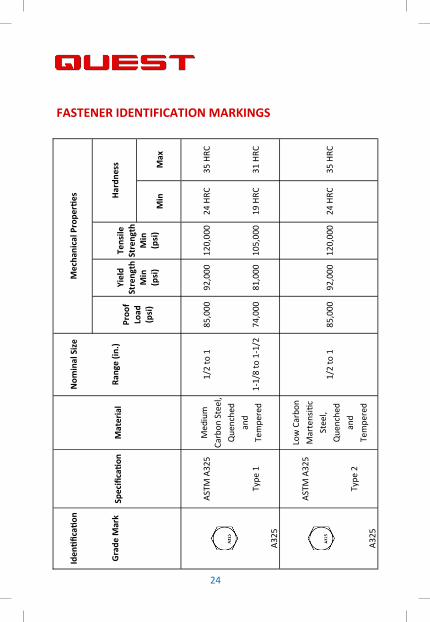
) FASTENER IDENTIFICATION MARKINGS
B8SH
B8M
SH
B8M
B8
B16
24
Iden
�fic
a�on
Spec
ifica
�on
M
ater
ial
Nom
inal
Siz
e M
echa
nica
l Pro
per�
es
Gra
de M
ark
Rang
e (in
.) Yi
eld
Stre
ngth
M
in
(psi
)
Tens
ile
Stre
ngth
M
in
(psi
)
Har
dnes
s
Min
M
ax
AS
TM
A3
25
M
ed
ium
Ca
rbo
n S
tee
l,
Qu
en
che
d
an
d
Te
mp
ere
d
1/2
to
1
85
,00
0
92
,00
0
12
0,0
00
2
4 H
RC
3
5 H
RC
A3
25
Typ
e 1
1
-1/8
to
1-1
/2
74
,00
0
81
,00
0
10
5,0
00
1
9 H
RC
3
1 H
RC
AS
TM
A3
25
Lo
w C
arb
on
Ma
rte
nsi
$c
Ste
el,
Qu
en
che
d
an
d
Te
mp
ere
d
1/2
to
1
85
,00
0
92
,00
0
12
0,0
00
2
4 H
RC
3
5 H
RC
A3
25
Typ
e 2
Proo
f Lo
ad
(psi
)
FASTENER IDENTIFICATION MARKINGS

25
AS
TM
A3
25
A
tmo
sph
eri
c
Co
rro
sio
n
Re
sis$
ng
Ste
el,
Qu
en
che
d
an
d T
em
-
pe
red
1/2
to
1
85
,00
0
92
,00
0
12
0,0
00
2
4 H
RC
3
5 H
RC
A3
25
Typ
e 3
1
-1/8
to
1-1
/2
74
,00
0
81
,00
0
10
5,0
00
1
9 H
RC
3
1 H
RC
AS
TM
A3
54
1/4
to
2-1
/2
10
5,0
00
1
09
,00
0
12
5,0
00
26
HR
C
36
HR
C
Gra
de
BC
2
-3/4
to
4
95
,00
0
99
,00
0
11
5,0
00
22
HR
C
33
HR
C
BC

26
Iden
�fic
a�on
Spec
ifica
�on
M
ater
ial
Nom
inal
Siz
e M
echa
nica
l Pro
per�
es
Gra
de M
ark
Rang
e (in
.) Yi
eld
Stre
ngth
M
in
(psi
)
Tens
ile
Stre
ngth
M
in
(psi
)
Har
dnes
s
Min
M
ax
No
Gra
de
Ma
rk
SA
E J
42
9
Low
or
Me
diu
m
Ca
rbo
n S
tee
l
1/4
to
1-1
/2
33
,00
0
36
,00
0
60
,00
0
70
HR
B
10
0 H
RB
Gra
de
1
AS
TM
A3
07
Lo
w C
arb
on
Ste
el
1/4
to
4
--
--
A -
69
HR
B
A -
10
0
HR
B
Gra
de
s A
&B
B
- 6
9
HR
B
B -
95
HR
B
SA
E J
42
9
Low
or
Me
diu
m
Ca
rbo
n S
tee
l
1/4
to
3/4
5
5,0
00
5
7,0
00
7
4,0
00
8
0 H
RB
1
00
HR
B
Gra
de
2
Ove
r 3
/4 t
o
1-1
/2
33
,00
0
36
,00
0
60
,00
0
70
HR
B
10
0 H
RB
Proo
f Lo
ad
(psi
)
FASTENER IDENTIFICATION MARKINGS

27
S
AE
J4
29
1/4
to
1
85
,00
0
92
,00
0
12
0,0
00
2
5 H
RC
3
4 H
RC
G
rad
e 5
Ove
r 1
to
1-1
/2
74
,00
0
81
,00
0
10
5,0
00
1
9 H
RC
3
0 H
RC
SA
E J
42
9
Me
diu
m
Ca
rbo
n A
llo
y
Ste
el,
Qu
en
che
d
an
d
Te
mp
ere
d
1/4
to
1-1
/2
12
0,0
00
1
30
,00
0
15
0,0
00
3
3 H
RC
G
rad
e 8
AS
TM
A3
54
Gra
de
BD
AS
TM
A4
90
All
oy
Ste
el,
Qu
en
che
d
an
d
Te
mp
ere
d
1/2
to
1-1
/2
12
0,0
00
1
30
,00
0
15
0,0
00
min
17
0,0
00
ma
x
33
HR
C
38
HR
C
A4
90
39
HR
C

28
NOTES:
1. In addi$on to the indicated grade marking, all grades included in this
table must be marked for manufacturer iden$fica$on.
2. While hex heads are shown, grade markings apply equally to products
with other head configura$ons.
3. Hardness value are Brinell.
4. A325 Type 1 bolts may also be marked with 3 radial lines 120 degrees
apart in addi$on to the A325 marking.
5. The bolt manufacturer, at his op$on, may add other markings to
indicate the use of atmospheric corrosion resistant steel.
6. A354 Grade BD products, in sizes 1-1/2” and smaller, are iden$fied as
shown and, at the manufacturer’s op$on, may have the leBers BD added.
Larger sizes are marked only BD.
7. Specifica$ons:
SAE J429 Mechanical and material requirements for externally threaded
fasteners
ASTM A307 Carbon steel externally threaded standard fasteners
ASTM A449 Quenched and tempered steel bolts and studs
ASTM 325 High strength bolts for structural steel joints
ASTM A354 Quenched and tempered alloy steel bolts, studs and other
externally threaded fasteners
ASTM A490 Heat treated steel structural bolts, 150 ksi minimum tensile
strength
ASTM A193-B7 Quenched and tempered alloy steel heavy hex bolts
FASTENER IDENFICIATION MARKING

29
BOLT STUD UN BOLT UNC BOLT UNF WRENCH DIAMETER THREADS THREADS THREADS SIZES
(Inches) (Inches) (Inches) (Inches) (Heavy Hex) 1/4" 20 20 28
5/16" 18 18 24
3/8" 16 16 24
7/16" 14 14 20
1/2" 13 13 20 7/8
9/16" 12 12 18
5/8" 11 11 18 1-1/16
3/4" 10 10 16 1-1/4
7/8" 9 9 14 1-7/16
1" 8 8 12 1-5/8
1-1/8" 8 7 12 1-13/16
1-1/4" 8 7 12 2
1-3/8" 8 6 12 2-3/16
1-1/2" 8 6 2-3/8
1-5/8" 8 Not Defined 2-9/16
1-3/4" 8 5 2-3/4
1-7/8" 8 Not Defined 2-15/16
2" 8 4-1/2 3-1/8
2-1/4" 8 4 3-1/2
2-1/2" 8 4 3-7/8
2-3/4" 8 4 4-1/4
3" 8 4 4-5/8
3-1/4" 8 4 5
3-1/2" 8 4
3-3/4" 8 4
4" 8 4
STUD & BOLT THREAD PITCHES

30
MEASUREMENT INFORMATION
Measurement Ordering Informa�on:
We suggest conforming to the Industrial Fasteners Ins$tute®
measures as shown above, known as first-thread-to-first-thread
measurement (L). Flat chamfer points are not included in this
measurement. Ordering by overall length is known as end-to-end
measurement as should be clearly specified when ordering. Hex
Bolts are measured from under the head to the $p of the bolt.
Tolerances on Stud Bolt Lengths:
All our studs have been manufactured according to the
requirements of ANSI standard B16.5, as outlined by the Industrial
Fasteners Ins$tute®. The length Tolerances are as follows:
Length in Inches Tolerances in Inches
Lengths up to 12” + or - 1/16
Lengths over 12” + or - 1/8
31
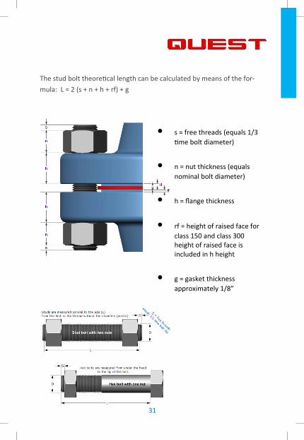
The stud bolt theore$cal length can be calculated by means of the for-
mula: L = 2 (s + n + h + rf) + g
• s = free threads (equals 1/3
$me bolt diameter)
• n = nut thickness (equals
nominal bolt diameter)
• h = flange thickness
• rf = height of raised face for
class 150 and class 300
height of raised face is
included in h height
• g = gasket thickness
approximately 1/8”

32
U-BOLT WASHERS
Bolt Size Outside Inside
Thickness Approx. Approx.
Diameter Diameter per M Pcs per Carton 3/8 0.813 0.406 0.138 15.3 3,500
7/16 0.922 0.469 0.138 20 2,700
1/2 1.125 0.526 0.187 42 1,300
9/16 1.187 0.593 0.187 44.2 1,200
5/8 1.25 0.656 0.187 48 1,100
3/4 1.375 0.781 0.187 54 950
7/8 1.5 0.906 0.187 60 830
1 1.625 1.031 0.187 66 680
1 1/8 2.25 1.156 0.25 208 250
1 1/4 2.25 1.312 0.25 186 220
SAE WASHERS
Bolt Size Outside Inside SAE Thick-
ness
Approx.
Lbs.
Approx.
pcs
Diameter Diameter per M Pcs per Carton
1/2 1.063 0.531 .074/.121 17.8 2,800
5/8 1.313 0.656 .074/.121 27.1 1,850
3/4 1.469 0.813 .108/.160 44.7 1,050
7/8 1.75 0.938 .108/.160 64.6 775
1 2 1.063 .108/.160 85 585
1 1/8 2.25 1.25 .108/.160 109 460
1 1/4 2.5 1.375 .136/.192 151 335
1 3/8 2.75 1.5 .136/.192 181 275
1 1/2 3 1.625 .136/.192 212 230

33
F436 WASHERS
Bolt Size Outside Inside F436 Thick-
ness
Approx.
Lbs.
Approx.
pcs Diameter Diameter per M Pcs per Carton
1/2 1.063 0.531 .097/.177 20 2,500
5/8 1.313 0.688 .122/.177 35 1,250
3/4 1.469 0.813 .122/.177 41.2 1,125
7/8 1.75 0.938 .136/.177 71 625
1 2 1.063 .136/.177 93.8 500
1 1/8 2.25 1.188 .136/.177 120 375
1 1/4 2.5 1.375 .136/.177 144 300
1 3/8 2.75 1.531 .136/.177 174 275
1 1/2 3 1.625 .136/.177 208 250
1 5/8 3.25 1.77 .178/.280 311 150
1 3/4 3.375 1.875 .178/.280 328 130
1 7/8 3.5 2 .178/.280 345 135
2 3.75 2.125 .178/.280 398 100
2 1/4 4 2.407 .240/.340 568 60
2 1/2 4.5 2.657 .240/.340 734 30
2 3/4 5 2.907 .240/.340 921 30
3 5.5 3.157 .240/.340 1129 30

34
TYPE 137 STANDARD PIPE DIMENSIONS
Pipe Size Material
Diameter C L T
Approx.
wt. per 100
1/2" 1/4" 15/16 3 1/4 2 3/8 7.4
3/4" 1/4" 1 1/8 3 5/16 2 3/8 7.7
1" 1/4" 1 3/8 3 7/16 2 3/8 8.1
1/2" 3/8" 15/16 3 1/4 2 3/8 19
3/4" 3/8" 1 1/8 3 5/16 2 3/8 19.7
1" 3/8" 1 3/8 3 7/16 2 3/8 21
1 1/4" 3/8" 1 11/16 3 3/4 2 3/8 22.5
1 1/2" 3/8" 2 4 2 1/2 24.3
2" 3/8" 2 7/16 4 1/2 2 1/2 27.3
2 1/2" 1/2" 2 15/16 5 1/4 3 57.3
3" 1/2" 3 9/16 5 13/16 3 63.5
3 1/2" 1/2" 4 1/16 6 5/16 3 69.4
4 " 1/2" 4 9/16 6 13/16 3 74.9
5" 1/2" 5 5/8 7 13/16 3 86.7
6" 5/8" 6 3/4 9 1/2 3 3/4 162
8" 5/8" 8 3/4 11 1/2 3 3/4 200.4
10" 3/4" 10 7/8 13 13/16 4 364.6
12" 7/8" 12 7/8 16 1/16 4 1/4 561.7
14" 7/8" 14 1/8 17 5/16 4 1/4 619.8
16" 7/8" 16 1/8 19 5/16 4 1/4 676.6
18" 1" 18 1/8 21 11/16 4 3/4 1040
20" 1" 20 1/8 23 11/16 4 3/4 1130
24" 1" 24 1/8 27 11/16 4 3/4 1330
30" 1" 30 1/8 33 11/16 4 3/4 1620
36" 1" 36 1/8 39 11/16 4 3/4 1900
35
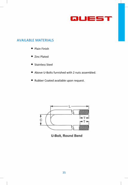
AVAILABLE MATERIALS
• Plain Finish
• Zinc Plated
• Stainless Steel
• Above U-Bolts furnished with 2 nuts assembled.
• Rubber Coated available upon request.

36
ANSI 150 LB
NOMINAL
PIPE SIZE
DIAMETER
OF STUDS
NO. OF
STUDS
STUD BOLT LENGTHS RING JOINT
GASKET
NO. RAISED
FACED RING JOINT
1/2 1/2 4 2 1/4 - -
3/4 1/2 4 2 1/2 - -
1 1/2 4 2 1/2 3 R15
1 1/4 1/2 4 2 3/4 3 1/4 R17
1 1/2 1/2 4 2 3/4 3 1/4 R19
2 5/8 4 3 1/4 3 3/4 R22
2 1/2 5/8 4 3 1/2 4 R25
3 5/8 4 3 1/2 4 1/4 R29
3 1/2 5/8 8 3 1/2 4 1/4 R33
4 5/8 8 3 1/2 4 1/4 R36
5 3/4 8 3 3/4 4 1/2 R40
6 3/4 8 4 4 1/2 R43
8 3/4 8 4 1/4 4 3/4 R48
10 7/8 12 4 3/4 5 1/4 R52
12 7/8 12 4 3/4 5 1/2 R56
14 1 12 5 1/4 6 R59
16 1 16 5 1/2 6 R64
18 1 1/8 16 6 6 1/2 R68
20 1 1/8 20 6 1/4 7 R72
22 1 1/4 20 6 1/2 7 1/4 R80
24 1 1/4 20 7 7 3/4 R76
ANSI B16.5 BOLTING CHART

37
ANSI 300 LB
NOMINAL
PIPE SIZE
DIAMETER
OF STUDS
NO. OF
STUDS
STUD BOLT LENGTHS RING JOINT
GASKET
NO. RAISED
FACED RING JOINT
1/2 1/2 4 2 1/2 3 R11
3/4 5/8 4 3 3 1/4 R13
1 5/8 4 3 1/4 3 1/4 R16
1 1/4 5/8 4 3 1/4 3 3/4 R18
1 1/2 3/4 4 3 1/2 4 R20
2 5/8 8 3 1/2 4 1/4 R23
2 1/2 3/4 8 4 4 1/2 R26
3 3/4 8 4 1/4 5 R31
3 1/2 3/4 8 4 1/4 5 R34
4 3/4 8 4 1/2 5 1/4 R37
5 3/4 8 4 3/4 5 1/4 R41
6 3/4 12 4 3/4 5 3/4 R45
8 7/8 12 5 1/2 6 1/4 R49
10 1 16 6 1/4 7 1/4 R53
12 1 1/8 16 6 3/4 7 1/2 R57
14 1 1/8 20 7 7 3/4 R61
16 1 1/4 20 7 1/2 8 1/4 R65
18 1 1/4 24 7 3/4 8 1/2 R69
20 1 1/4 24 8 1/4 9 1/4 R73
22 1 1/2 24 8 3/4 9 3/4 R81
24 1 1/2 24 9 1/4 10 1/4 R77
ANSI B16.5 BOLTING CHART

38
ANSI 400 LB
NOMINAL
PIPE SIZE
DIAMETER
OF STUDS
NO. OF
STUDS
STUD BOLT LENGTHS RING JOINT
GASKET
NO. RAISED
FACED RING JOINT
1/2 1/2 4 3 3 R11
3/4 5/8 4 3 1/2 3 1/2 R13
1 5/8 4 3 1/2 3 1/2 R16
1 1/4 5/8 4 3 3/4 3 3/4 R18
1 1/2 3/4 4 4 1/4 4 1/4 R20
2 5/8 8 4 1/4 4 1/4 R23
2 1/2 3/4 8 4 3/4 4 3/4 R26
3 3/4 8 5 5 R31
3 1/2 7/8 8 5 1/2 5 1/2 R34
4 7/8 8 5 1/2 5 1/2 R37
5 7/8 8 5 3/4 5 3/4 R41
6 7/8 12 6 6 R45
8 1 12 6 3/4 6 3/4 R49
10 1 1/8 16 7 1/2 7 1/2 R53
12 1 1/4 16 8 8 R57
14 1 1/4 20 8 1/4 8 1/4 R61
16 1 3/8 20 8 3/4 8 3/4 R65
18 1 3/8 24 9 9 R69
20 1 1/2 24 9 1/2 9 1/2 R73
22 1 5/8 24 10 10 1/2 R81
24 1 3/4 24 10 1/2 11 R77
ANSI B16.5 BOLTING CHART

39
ANSI 600 LB
NOMINAL
PIPE SIZE
DIAMETER
OF STUDS
NO. OF
STUDS
STUD BOLT LENGTHS RING JOINT
GASKET
NO. RAISED
FACED RING JOINT
1/2 1/2 4 3 3 R11
3/4 5/8 4 3 1/4 3 1/4 R13
1 5/8 4 3 1/2 3 1/2 R16
1 1/4 5/8 4 3 3/4 3 3/4 R18
1 1/2 3/4 4 4 1/4 4 1/4 R20
2 5/8 8 4 1/4 4 1/2 R23
2 1/2 3/4 8 5 5 1/4 R26
3 3/4 8 5 5 1/4 R31
3 1/2 7/8 8 5 1/2 5 1/2 R34
4 7/8 8 5 3/4 6 R37
5 1 8 6 1/2 6 1/2 R41
6 1 12 6 3/4 7 R45
8 1 1/8 12 7 3/4 8 R49
10 1 1/4 16 8 1/2 8 3/4 R53
12 1 1/4 20 8 3/4 9 R57
14 1 3/8 20 9 1/4 9 1/2 R61
16 1 1/2 20 10 10 1/4 R65
18 1 5/8 20 10 3/4 11 R69
20 1 5/8 24 11 1/2 11 3/4 R73
22 1 3/4 24 12 12 1/2 R81
24 1 7/8 24 13 13 1/2 R77
ANSI B16.5 BOLTING CHART

40
ANSI 900 LB
NOMINAL
PIPE SIZE
DIAMETER
OF STUDS
NO. OF
STUDS
STUD BOLT LENGTHS RING JOINT
GASKET
NO. RAISED
FACED RING JOINT
1/2 3/4 4 4 4 1/4 R12
3/4 3/4 4 4 1/4 4 1/2 R14
1 7/8 4 4 3/4 5 R16
1 1/4 7/8 4 5 5 R18
1 1/2 1 4 5 1/4 5 1/2 R20
2 7/8 8 5 1/2 5 3/4 R24
2 1/2 1 8 6 1/4 6 1/4 R27
3 7/8 8 5 1/2 5 3/4 R31
4 1 1/8 8 6 1/2 6 3/4 R37
5 1 1/4 8 7 1/2 7 1/2 R41
6 1 1/8 12 7 1/2 7 3/4 R45
8 1 3/8 12 8 1/2 8 3/4 R49
10 1 3/8 16 9 9 1/4 R53
12 1 3/8 20 9 3/4 10 R57
14 1 1/2 20 10 1/2 11 R62
16 1 5/8 20 11 11 1/2 R66
18 1 7/8 20 12 3/4 13 1/4 R70
20 2 20 13 1/2 14 1/4 R74
24 2 1/2 20 17 18 R78
ANSI B16.5 BOLTING CHART

41
ANSI 1500 LB
NOMINAL
PIPE SIZE
DIAMETER
OF STUDS
NO. OF
STUDS
STUD BOLT LENGTHS RING JOINT
GASKET
NO. RAISED
FACED RING JOINT
1/2 3/4 4 4 4 1/4 R12
3/4 3/4 4 4 1/4 4 1/2 R14
1 7/8 4 4 3/4 5 R16
1 1/4 7/8 4 5 5 R18
1 1/2 1 4 5 1/4 5 1/2 R20
2 7/8 8 5 1/2 5 3/4 R24
2 1/2 1 8 6 1/4 6 1/4 R27
3 1 1/8 8 6 3/4 7 R35
4 1 1/4 8 7 1/2 7 3/4 R39
5 1 1/2 8 9 3/4 9 3/4 R44
6 1 3/8 12 10 10 1/2 R46
8 1 5/8 12 11 1/4 11 3/4 R50
10 1 7/8 12 13 1/4 13 1/2 R54
12 2 16 14 3/4 15 1/4 R58
14 2 1/4 16 16 16 3/4 R63
16 2 1/2 16 17 1/2 18 1/2 R67
18 2 3/4 16 19 1/4 20 1/4 R71
20 3 16 21 22 1/4 R75
24 3 1/2 16 24 25 1/2 R79
ANSI B16.5 BOLTING CHART

42
ANSI 2500 LB
NOMINAL
PIPE SIZE
DIAMETER
OF STUDS
NO. OF
STUDS
STUD BOLT LENGTHS RING JOINT
GASKET
NO. RAISED
FACED RING JOINT
1/2 3/4 4 4 3/4 4 3/4 R13
3/4 3/4 4 4 3/4 5 R16
1 7/8 4 5 1/4 5 1/2 R18
1 1/4 1 4 6 6 R21
1 1/2 1 1/4 4 6 1/2 6 3/4 R23
2 1 8 6 3/4 7 R26
2 1/2 1 1/4 8 7 3/4 8 R28
3 1 1/4 8 8 1/2 9 R32
4 1 1/2 8 9 3/4 10 1/4 R38
5 1 3/4 8 11 3/4 12 1/4 R42
6 2 8 13 1/2 14 R47
8 2 12 15 15 1/2 R51
10 2 1/2 12 19 20 R55
12 2 3/4 12 21 22 R60
ANSI B16.5 BOLTING CHART

43
2,000 LB W.P.
NOMINAL
SIZE
GASKET API
NUMBER
NUMBER OF
STUDS
STUD BOLT
DIAMETER
STUD BOLT
LENGTH
2 1/16 R23 8 5/8 4 1/2
2 9/16 R26 8 3/4 5
3 1/8 R31 8 3/4 5 1/4
4 1/16 R37 8 7/8 6
5 1/8 R41 8 1 6 3/4
7 1/16 R45 12 1 7
9 R49 12 1 1/8 8
11 R53 16 1 1/4 8 3/4
13 5/8 R57 20 1 1/4 9
16 3/4 R65 20 1 1/2 10 1/4
21 1/4 R73 24 1 5/8 11 3/4
26 3/4 BX167 20 1 3/4 13 3/4
API FLANGE BOLTING CHART

44
3,000 LB W.P.
NOMINAL
SIZE
GASKET API
NUMBER
NUMBER OF
STUDS
STUD BOLT
DIAMETER
STUD BOLT
LENGTH
3 1/8 R31 8 7/8 6
4 1/16 R37 8 1 1/8 7
5 1/8 R41 8 1 1/4 7 3/4
7 1/16 R45 12 1 1/8 8
9 R49 12 1 3/8 9
11 R53 16 1 3/8 9 1/2
13 5/8 R57 20 1 3/8 10 1/4
16 3/4 R66 20 1 5/8 11 3/4
20 3/4 R74 20 2 14 1/2
26 3/4 BX168 24 2 17
API FLANGE BOLTING CHART

45
API FLANGE BOLTING CHART
5,000 LB W.P.
NOMINAL
SIZE
GASKET API
NUMBER
NUMBER OF
STUDS
STUD BOLT
DIAMETER
STUD BOLT
LENGTH
2 1/16 R24 8 7/8 6
2 9/16 R27 8 1 6 1/2
3 1/8 R35 8 1 1/8 7 1/4
4 1/16 R39 8 1 1/4 8
5 1/8 R44 8 1 1/2 10
7 1/16 R46 12 1 3/8 10 3/4
9 R50 12 1 5/8 12
11 R54 12 1 7/8 13 3/4
13 5/8 BX160 16 1 5/8 12 1/2
16 3/4 BX162 16 1 7/8 14 1/2
18 3/4 BX163 20 2 17 1/2
21 1/4 BX165 21 2 18 3/4
46
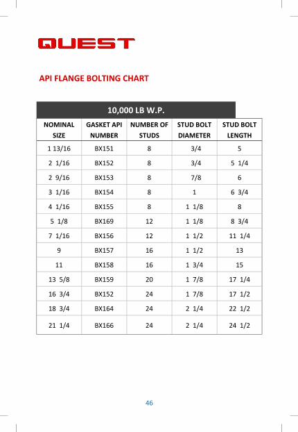
10,000 LB W.P.
NOMINAL
SIZE
GASKET API
NUMBER
NUMBER OF
STUDS
STUD BOLT
DIAMETER
STUD BOLT
LENGTH
1 13/16 BX151 8 3/4 5
2 1/16 BX152 8 3/4 5 1/4
2 9/16 BX153 8 7/8 6
3 1/16 BX154 8 1 6 3/4
4 1/16 BX155 8 1 1/8 8
5 1/8 BX169 12 1 1/8 8 3/4
7 1/16 BX156 12 1 1/2 11 1/4
9 BX157 16 1 1/2 13
11 BX158 16 1 3/4 15
13 5/8 BX159 20 1 7/8 17 1/4
16 3/4 BX152 24 1 7/8 17 1/2
18 3/4 BX164 24 2 1/4 22 1/2
21 1/4 BX166 24 2 1/4 24 1/2
API FLANGE BOLTING CHART
47
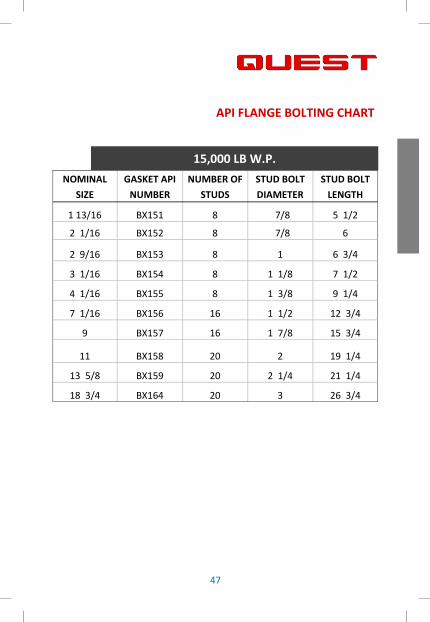
15,000 LB W.P.
NOMINAL
SIZE
GASKET API
NUMBER
NUMBER OF
STUDS
STUD BOLT
DIAMETER
STUD BOLT
LENGTH
1 13/16 BX151 8 7/8 5 1/2
2 1/16 BX152 8 7/8 6
2 9/16 BX153 8 1 6 3/4
3 1/16 BX154 8 1 1/8 7 1/2
4 1/16 BX155 8 1 3/8 9 1/4
7 1/16 BX156 16 1 1/2 12 3/4
9 BX157 16 1 7/8 15 3/4
11 BX158 20 2 19 1/4
13 5/8 BX159 20 2 1/4 21 1/4
18 3/4 BX164 20 3 26 3/4
API FLANGE BOLTING CHART

48
25,000 LB W.P.
NOMINAL
SIZE
GASKET API
NUMBER
NUMBER OF
STUDS
STUD BOLT
DIAMETER
STUD BOLT
LENGTH
1 13/16 BX151 8 1 7 1/2
2 1/16 BX152 8 1 1/8 8 1/4
2 9/16 BX153 8 1 1/4 9 1/4
3 1/8 BX154 8 1 3/8 10
4 1/16 BX155 8 1 3/4 12 1/4
7 1/16 BX156 16 2 17 1/2
9 BX157 16 2 1/2 22 1/2
11 BX158 20 2 3/4 23 3/4
13 5/8 BX159 20 3 30
API FLANGE BOLTING CHART

50
BOLT TORQUE VALUES NOTES
Standard Bolt Torque
1. Tightening torque values from the formula T=KDP, where T = $ghtening torque,
lb. F. K - torque fric$on coefficient, D = nominal bolt diameter, in.; and P = bolt
clamping load developed by $ghtening, lb.
Note: Dry K = 0.22, Lubed K = 0.17
2. No proof load has been established by ASTM. Value shown in table are assumed
at 95% of yield strength.
3. Proof load is the published number that full size headed bolts are tested to. The
bolt is stressed up to the proof load value, and if there is no deforma$on,
elonga$on, or fracture, then the bolt is deemed to have passed. For bol$ng
specifica$ons that do not have a published proof load, it is usually calculated at 92%
of ul$mate yield strength.
4. Clamp load is also known as preload or ini$al load in tension on bolt. Clamp load
(lb.) is calculated by arbitrarily assuming useable bolt strength is 75% of bolt proof
load (PSI) $mes the stress area (sq. in.) of threaded sec$on of each bolt size. Higher
or lower values of clamp load can be used depending on the applica$on
requirements and the judgment of the designer. The Maximum Bolt Torque chart is
based on these values.
5. It is not generally recommend that bolt stress be above 60,000 psi (60ksi).
Extreme opera$ng condi$ons such as high temperature may reduce bolt yield
strength. Cau$on should be used in these applica$ons.
51
Gasket Bolt Torque
Gasket Bolt Charts are suggested torque values using ASTM A193 B7 bol$ng or
equal yield strength bolt material and ASME B16.5 raised face flanges.
Charts are based on Fric$on Factor (K) of 0.17
Use correct size and new bolts, studs, nuts, washers. Mul$ply torques values by
0.70 for PTFE coated bol$ng. Lubricate on bolt threads and nut faces with
compa$ble an$-seize. The charts give the torque value for the final pass. AFer hand
$ghtening, torqueing must follow a cross bol$ng sequence. There shall be 3
complete passes (30%, 60%, 100% of final pass torque). Once final torque is
achieved, a minimum of 2 clockwise passes to be applied un$l there is no further
nut rota$on.
ASME B16.20-2017 states that inward bucking of spiral wound gaskets has been
iden$fied as a poten$al problem. It is recommended that inner rings be used.
Your specific applica�on should not be undertaken without independent study
and evalua�on for suitability. For specific applica�on recommenda�ons consult
QUEST. Failure to select proper sealing products could result in property damage
and/or serious personal injury.
Ring Type Joint Gasket Bolt Torque
The torque values reprinted in these tables are guidelines only and are the exclusive
property of API.
Note: Calcula$ons based on K = 0.07 for PTFE (Teflon/Xylan) coa$ngs and K = 0.13
for commonly available an$-seize lubricants.
All values are approximate. No assump$on of liability by API or Quest is implied or
assumed for the use of this informa$on.
BOLT TORQUE VALUE NOTES

52
MAXIMUM BOLT TORQUE VALUES
ALLOY STEEL BOLT ASTM A193 B7, A320 L7
See Bolt Torque Value Notes
Stud Dia.
(inches)
Threads Per
Inch (TPI)
Tensile Stress Area (Sq. Inch)
Yield Strength = 105 ksi
Bolt Stress = 75 ksi
Clamp Load Dry Lubed
P. Lbs. FT-LB Torque FT-LB Torque
1/2 13 0.142 10,616 97 75
5/8 11 0.226 16,908 194 150
3/4 10 0.334 25,022 344 266
7/8 9 0.462 34,544 554 428
1 8 0.606 45,317 831 642
1 1/8 8 0.790 59,136 1,220 942
1 1/4 8 1.000 74,791 1,714 1,324
1 3/8 8 1.234 92,281 2,326 1,798
1 1/2 8 1.492 111,609 3,069 2,372
1 5/8 8 1.775 132,772 3,955 3,057
1 3/4 8 2.082 155,771 4,998 3,862
1 7/8 8 2.414 180,607 6,208 4,797
2 8 2.771 207,279 7,600 5,873
2 1/4 8 3.557 266,131 10,978 8,483
2 1/2 8 4.442 332,328 15,232 11,770

53
Stud Dia.
(inches)
Threads Per
Inch (TPI)
Tensile Stress Area (Sq. Inch)
Yield Strength = 80 ksi
Bolt Stress = 57 ksi
Clamp Load Dry Lubed
P. Lbs. FT-LB Torque FT-LB Torque
1/2 13 0.142 8,088 74 57
5/8 11 0.226 12,882 148 114
3/4 10 0.334 19,064 262 203
7/8 9 0.462 26,319 422 326
1 8 0.606 34,527 633 489
1 1/8 8 0.790 45,056 929 718
1 1/4 8 1.000 56,983 1,306 1,009
1 3/8 8 1.234 70,310 1,772 1,370
1 1/2 8 1.492 85,035 2,338 1,807
1 5/8 8 1.775 101,159 3,014 2,329
1 3/4 8 2.082 118,683 3,808 2,942
1 7/8 8 2.414 137,605 4,730 3,655
2 8 2.771 157,927 5,791 4,475
2 1/4 8 3.557 202,766 8,364 6,463
2 1/2 8 4.442 253,202 11,605 8,968
MAXIMUM BOLT TORQUE VALUES
ALLOY STEEL BOLT ASTM A193M B7M, A320 L7M
See Bolt Torque Value Notes

54
MAXIMUM BOLT TORQUE VALUES
LARGE DIAMETER
ALLOY STEEL BOLT ASTM A193 B7, A320, L43
See Bolt Torque Value Notes
Stud Dia.
(inches)
Threads Per
Inch (TPI)
Tensile Stress Area (Sq. Inch)
Yield Strength = 105 ksi
Bolt Stress = 75 ksi
Clamp Load Dry Lubed
P. Lbs. FT-LB Torque FT-LB Torque
2 3/4 8 5.425 367,215 18,514 14,306
3 8 6.506 440,398 24,222 18,717
3 1/4 8 7.686 520,226 30,997 23,952
3 1/2 8 8.963 606,699 38,930 30,082
3 3/4 8 10.339 699,818 48,112 37,178
4 8 11.813 799,581 58,636 45,310
55
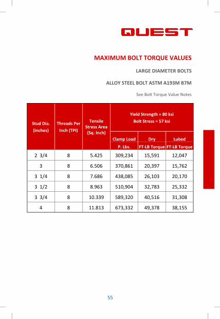
MAXIMUM BOLT TORQUE VALUES
LARGE DIAMETER BOLTS
ALLOY STEEL BOLT ASTM A193M B7M
See Bolt Torque Value Notes
Stud Dia.
(inches)
Threads Per
Inch (TPI)
Tensile Stress Area (Sq. Inch)
Yield Strength = 80 ksi
Bolt Stress = 57 ksi
Clamp Load Dry Lubed
P. Lbs. FT-LB Torque FT-LB Torque
2 3/4 8 5.425 309,234 15,591 12,047
3 8 6.506 370,861 20,397 15,762
3 1/4 8 7.686 438,085 26,103 20,170
3 1/2 8 8.963 510,904 32,783 25,332
3 3/4 8 10.339 589,320 40,516 31,308
4 8 11.813 673,332 49,378 38,155

56
SUGGESTED BOLT TORQUE VALUES AT CORRESPONDING
BOLT STRESSES
ALLOY STEEL BOLTS: ASTM A193 B7, A320 L7, A193M B7M, A320 L7M
See Bolt Torque Value Notes
Stud Dia (Inches)
Threads Per Inch
Tensile Stress Area
(Sq. Inch)
Bolt Stress = 60 ksi Bolt Stress = 45 ksi
Tension F (lbf)
Lubed Torque (K-lbf)
Tension F (lbf)
Lubed Torque (K-lbf)
1/2 13 0.142 8,514 60 6,385 45
5/8 11 0.226 13,560 120 10,170 90
3/4 10 0.334 20,068 213 15,051 160
7/8 9 0.462 27,704 343 20,778 258
1 8 0.606 36,345 515 27,259 386
1 1/8 8 0.790 47,427 756 35,570 567
1 1/4 8 1.000 59,982 1,062 44,987 797
1 3/8 8 1.234 74,010 1,442 55,508 1,081
1 1/2 8 1.492 89,511 1,902 67,133 1,427
1 5/8 8 1.775 106,484 2,451 79,863 1,839
1 3/4 8 2.082 124,929 3,097 93,697 2,323
1 7/8 8 2.414 144,848 3,848 108,636 2,886
2 8 2.771 166,238 4,710 124,679 3,533
2 1/4 8 3.557 213,438 6,803 160,079 5,103
2 1/2 8 4.442 266,528 9,440 199,896 7,080

57
SUGGESTED BOLT TORQUE VALUES AT CORRESPONDING
BOLT STRESSES
ALLOY STEEL BOLTS: ASTM A193 B7, A320 L7, A193M B7M, A320 L7M
See Bolt Torque Value Notes
Stud Dia (Inches)
Threads Per Inch
Tensile Stress Area (Sq. Inch)
Bolt Stress = 30 ksi Bolt Stress = 25 ksi (Low Torque)
Tension F (lbf)
Lubed Torque (K-lbf)
Tension F (lbf)
Lubed Torque (K-lbf)
1/2 13 0.142 4,257 30 3,547 25
5/8 11 0.226 6,780 60 5,650 50
3/4 10 0.334 10,034 107 8,362 89
7/8 9 0.462 13,852 172 11,543 143
1 8 0.606 18,172 257 15,144 215
1 1/8 8 0.790 23,714 378 19,761 315
1 1/4 8 1.000 29,991 531 24,993 443
1 3/8 8 1.234 37,005 721 30,838 601
1 1/2 8 1.492 44,755 951 37,296 793
1 5/8 8 1.775 53,242 1,226 44,368 1,021
1 3/4 8 2.082 62,465 1,549 52,054 1,291
1 7/8 8 2.414 72,424 1,924 60,353 1,603
2 8 2.771 83,119 2,355 69,266 1,963
2 1/4 8 3.557 106,719 3,402 88,933 2,835
2 1/2 8 4.442 133,264 4,720 111,053 3,933

58
API FLANGE (RTJ) SUGGESTED BOLT TORQUE VALUES
BOLTING TORQUE VALUES RECOMMENDED BY API-6A 20th EDITION
See Bolt Torque Value Notes
Threads Per
Inch (TPI)
ASTM A193/194, A320 (B7, L7)
Yield Strength = 105 ksi Bolt Stress = 52.5 ksi
Tension
F (lbf)
Torque Xylan
(K.-lbf)
Torque Lubed
(K.-lbf)
1/2 13 7,450 35 59
5/8 11 11,865 68 115
3/4 10 17,559 118 200
7/8 9 24,241 188 319
1 8 31,802 279 474
1 1/8 8 41,499 401 686
1 1/4 8 52,484 553 953
1 3/8 8 64,759 739 1,281
1 1/2 8 78,322 962 1,677
1 5/8 8 93,173 1,226 2,146
1 3/4 8 109,313 1,534 2,696
1 7/8 8 126,741 1,890 3,332
2 8 145,458 2,297 4,061
2 1/4 8 186,758 3,276 5,822
2 1/2 8 233,212 4,500 8,030
Stud Dia.
(inches)

59
API FLANGE (RTJ) SUGGESTED BOLT TORQUE VALUES
BOLTING TORQUE VALUES RECOMMENDED BY API-6A 20th EDITION
See Bolt Torque Value Notes
Threads Per
Inch (TPI)
ASTM A193M/194M, A320M (B7M, L7M)
Yield Strength = 80 ksi Bolt Stress = 40 ksi
Tension
F (lbf)
Torque Xylan
(K.-lbf)
Torque Lubed
(K.-lbf)
1/2 13 5,676 27 45
5/8 11 9,040 52 88
3/4 10 13,378 90 153
7/8 9 18,469 143 243
1 8 24,230 213 361
1 1/8 8 31,618 305 523
1 1/4 8 39,988 421 726
1 3/8 8 49,340 563 976
1 1/2 8 59,674 733 1,278
1 5/8 8 70,989 934 1,635
1 3/4 8 83,286 1,169 2,054
1 7/8 8 96,565 1,440 2,539
2 8 110,825 1,750 3,094
2 1/4 8 142,292 2,496 4,436
2 1/2 8 177,685 3,429 6,118
Stud Dia.
(inches)

60
SPIRAL WOUND SUGGESTED BOLT TORQUE VALUES
GASKET: TEADIT® STYLE 913M (WITH INNER AND OUTER RINGS)
See Bolt Torque Value Notes
Nominal Pipe Size
150 300 400 600 900 1500 2500
1/2 28 28 --- 28 --- 80 85
3/4 43 43 --- 57 --- 100 85
1 50 72 --- 86 --- 160 125
1 1/4 57 101 --- 86 --- 200 220
1 1/2 57 151 --- 159 --- 275 320
2 122 108 --- 86 --- 200 220
2 1/2 122 144 --- 122 --- 300 320
3 122 173 --- 180 265 400 450
3 1/2 122 202 --- 300 --- --- ---
4 122 202 325 296 500 650 750
5 202 202 325 448 840 1000 1300
6 202 202 325 448 590 900 2000
8 202 325 506 614 950 1400 2000
10 325 506 614 867 950 2400 3500
12 325 723 867 867 1130 2500 5000
14 506 614 867 1193 1330 3200
16 506 867 1193 1410 1830 4500
18 723 1012 1193 1880 3000 6000
20 723 1012 1410 1880 3000 7730
24 1012 1410 2603 3471 5000 12750
61
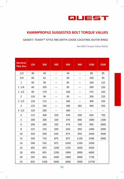
KAMMPROFILE SUGGESTED BOLT TORQUE VALUES
GASKET: TEADIT® STYLE 946 (WITH LOOSE LOCATING OUTER RING)
See Bolt Torque Value Notes
Nominal Pipe Size
150 300 400 600 900 1500 2500
1/2 40 40 --- 40 --- 80 85
3/4 60 65 --- 60 --- 100 85
1 60 90 --- 85 --- 160 125
1 1/4 60 105 --- 85 --- 200 220
1 1/2 60 170 --- 160 --- 275 320
2 120 90 --- 85 --- 200 220
2 1/2 120 115 --- 160 --- 300 320
3 125 160 --- 180 265 400 450
3 1/2 120 200 --- 300 --- --- ---
4 115 200 320 330 500 650 750
5 200 200 320 470 840 1000 1300
6 200 200 320 470 590 900 2000
8 225 320 500 650 950 1400 2000
10 320 500 620 875 950 2400 3500
12 320 710 875 875 1130 2500 5000
14 500 535 875 1020 1330 3200
16 405 835 1200 1335 1830 4500
18 650 835 1200 1900 3000 6000
20 595 835 1400 1900 3000 7730
24 835 1200 2600 3000 5000 12750

62
CORRUGATED METAL SUGGESTED BOLT TORQUE VALUES
GASKET: TEADIT STYLE 905 METALBEST®
See Bolt Torque Value Notes
Nominal Pipe Size
150 300
1/2 60 60
3/4 60 120
1 60 120
1 1/4 60 120
1 1/2 80 200
2 120 90
2 1/2 120 130
3 160 160
3 1/2 120 200
4 115 200
5 230 260
6 260 210
8 260 320
10 420 500
12 420 710
14 650 535
16 405 835
18 650 835
20 595 835
24 835 1300

63
SHEET GASKETING SUGGESTED BOLT TORQUE VALUES
GASKET: TEADIT® COMPRESSED FIBER, TEALON™, QUIMFLEX 24SH,
FLEXIBLE GRAPHITE 2660, 2661, 2663
See Bolt Torque Value Notes
Nominal Pipe Size
150 300
1/2 28 28
3/4 43 43
1 50 72
1 1/4 57 101
1 1/2 57 151
2 122 108
2 1/2 122 144
3 122 173
3 1/2 122 202
4 122 202
5 202 202
6 202 202
8 202 325
10 325 506
12 325 723
14 506 614
16 506 867
18 723 1012
20 723 835
24 1012 1410

64
Nominal Size
150 300 400 600 900 1500 2500
1 40 80 80 80 110 110 170
1 1/4 40 80 110 110 170 170 300
1 1/2 40 110 110 110 240 240 400
2 80 110 110 110 170 170 300
2 1/2 80 150 150 150 240 240 400
3 110 150 150 150 215 370 600
3 1/2 80 150 180 200
4 100 180 180 225 450 650 650
5 120 180 215 350 650 1000 1500
6 130 170 215 320 455 820 2300
8 130 265 320 450 820 1400 2400
10 215 320 450 650 850 2100 4900
12 220 450 650 675 870 2300 7900
14 320 450 625 820 1125 3400
16 320 650 820 1125 1430 4300
18 450 650 820 1430 2230 6200
20 450 650 1100 1400 2300 7800
22 460 1125 1425 1775
24 650 1200 1775 2230 5500 13000
26 650 1400 1750 2200 7400
28 650 1500 2200 2300 8400
30 650 1700 2300 2360 9500
32 1000 2000 2300 3900 10500
34 1000 2250 2350 3950 12400
36 1100 2300 2350 5500 13800
38 2300 4800 7000
40 1100 2400 5200 7200
42 1150 2400 5500 7400
INSULATION GASKET SUGGESTED BOLT TORQUE VALUES
See Bolt Torque Value Notes

65
INSULATION GASKET SUGGESTED BOLT TORQUE VALUES
Pressure 150 300 400 600 900 1500 2500
Opera$ng 285 740 990 1480 2220 3705 6170
Hydro Test 455 1135 1510 2245 3355 5585 9280
Torque Values obtained based on above Working and Hydro Test Pres-
sures (psi)
BOLT TORQUE SEQUENCE NOTES
When Installing the gasket and $ghtening cold, refer to Bolt Torque
Sequence Charts. "Hot Flow" of the gasket material may occur under
opera$ng condi$ons, resul$ng in loss of Bolt Pressure. It is advisable
therefore, to re-$ghten bolts aFer opera$ng temperature has been
reached - preferably at Zero Line Pressure and Ambient Temperature.
Under no circumstances should the system be allowed to return to
opera$ng Temperature WITHOUT re-checking and re-$ghtening bolts
where needed.
To provide even sealing pressure on a flange gasket kit it is
recommended that the bolts be "snugged" up in the sequence shown
un$l the flange faces are in contact with the gasket. AFer the flange
faces are in contact with the gasket, firmly $ghten the bolts in the same
sequence.
Note: G10/Viton or G10/Teflon Gaskets do not grease seal prior to
installa$on.
66
4 TO 20 HOLE, BOLT TORQUE SEQUENCE
Number bolts or flange holes with a “marker” as shown in the diagram.
Install each bolt with their nuts, washers and hand $ghten the nuts
following the numerical sequence of the diagram. The flanges should be
parallel and contac$ng uniformly across the gasket. If tools are used to
bring the flanges together the maximum force should be equal or less
than 10% of the target force. The stud length should have at least two
threads protrude beyond the nut.
Steps:
1. Tighten studs 1, 2, 3 and 4 with 30% of the final torque or force.
Ensure the flanges are parallel.
2. Tighten studs 1, 2, 3 and 4 with 60% of the final torque or force.
Ensure the flanges are parallel.
3. Tighten studs 1, 2, 3 and 4 with 100% of the final torque or force.
Ensure the flanges are parallel.
4. Tighten all studs with 100% of the final torque or force in a circular
pass. Ensure the flanges are parallel.
5. Repeat the fourth (4) step un$l the nuts no longer turn.

67
4 TO 20 HOLE, BOLT TORQUE SEQUENCE

68
24 HOLE, BOLT TORQUE SEQUENCE
Number bolts or flange holes with a “marker” as shown in the diagram.
Install each bolt with their nuts, washers and hand $ghten the nuts
following the numerical sequence of the diagram. The flanges should be
parallel and contac$ng uniformly across the gasket. If tools are used to
bring the flanges together the maximum force should be equal or less
than 10% of the target force. The stud length should have at least two
threads protrude beyond the nut.
Steps:
1. Tighten all studs in the numerical sequence as shown with 30% of
the final torque or force. Ensure the flanges are parallel.
2. Tighten all studs in the numerical sequence as shown with 60% of
the final torque or force. Ensure the flanges are parallel.
3. Tighten all studs in the numerical sequence as shown with 100% of
the final torque or force. Ensure the flanges are parallel.
4. Tighten all studs with 100% of the final torque or force in a circular
pass. Ensure the flanges are parallel.
5. Repeat the fourth (4) step un$l the nuts no longer turn.

69
24 HOLE, BOLT TORQUE SEQUENCE

70
24 OR MORE HOLE, BOLT TORQUE SEQUENCE
Number bolts or flange holes with a “marker” as shown in the diagram.
Install each bolt with their nuts, washers and hand $ghten the nuts
following the numerical sequence of the diagram. The flanges should be
parallel and contac$ng uniformly across the gasket. If tools are used to
bring the flanges together the maximum force should be equal or less
than 10% of the target force. The stud length should have at least two
threads protrude beyond the nut.
Steps:
1. Tighten studs 1, 2, 3, 4, 5, 6, 7 and 8 with 30% of the final torque or
force. Ensure the flanges are parallel.
2. Tighten studs 1, 2, 3, 4, 5, 6, 7 and 8 with 60% of the final torque or
force. Ensure the flanges are parallel.
3. Tighten studs 1, 2, 3, 4, 5, 6, 7 and 8 with 100% of the final torque
or force. Ensure the flanges are parallel.
4. Tighten all studs with 100% of the final torque or force in a circular
pass. Ensure the flanges are parallel.
5. Repeat the fourth (4) step un$l the nuts no longer turn.

71
24 OR MORE HOLE, BOLT TORQUE SEQUENCE

72