table of contents - boxpert operation... · tm= miter cut end - cut type at ... each new segment...
TRANSCRIPT

8 Operation –
1
8. Operation
The lighting flash with triangle symbol is intended to alert the user to the presence of “Dangerous Voltage” to constitute of electric shock to persons.
The exclamation point within a triangle is intended to alert the user to the presence of important operating and maintenance instructions in the manual.
Warning: Misuse of your machine or failure to establish a safe may result in discomfort or
serious injury. The front area of the machine, where the nozzle is situated (shown in picture below), is considered a danger zone. The operator's fingers, and or hands could get crushed by the bending fingers when they are being engaged/retracted and during the bending process. The area is clearly marked, and the operator is prohibited from putting hands, and or fingers in this vicinity while the machine is in operation.
Bending Section
SDS USA, Inc. Rotary Bender

8 Operation –
2
Operator’s Position: Stand in directly in front of the machine. Placement of keyboard and mouse: Position them in front of you to reduce your fatigue. Viewing of the display: Avoid source of glare or reflections. Lighting: Add correct lighting to your work effectiveness and comfort.
SDS USA, Inc. Rotary Bender
8 Operation –
3
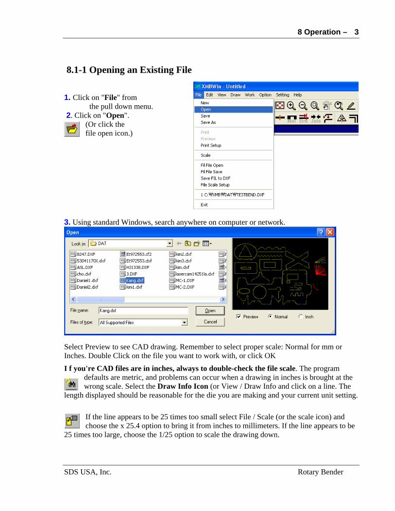
8.1-1 Opening an Existing File 1. Click on "File" from
the pull down menu. 2. Click on "Open".
(Or click the file open icon.)
3. Using standard Windows, search anywhere on computer or network.
Select Preview to see CAD drawing. Remember to select proper scale: Normal for mm or Inches. Double Click on the file you want to work with, or click OK
I f you're CAD files are in inches, always to double-check the file scale. The program defaults are metric, and problems can occur when a drawing in inches is brought at the wrong scale. Select the Draw Info Icon (or View / Draw Info and click on a line. The
length displayed should be reasonable for the die you are making and your current unit setting.
If the line appears to be 25 times too small select File / Scale (or the scale icon) and choose the x 25.4 option to bring it from inches to millimeters. If the line appears to be
25 times too large, choose the 1/25 option to scale the drawing down.
SDS USA, Inc. Rotary Bender
8 Operation –
4
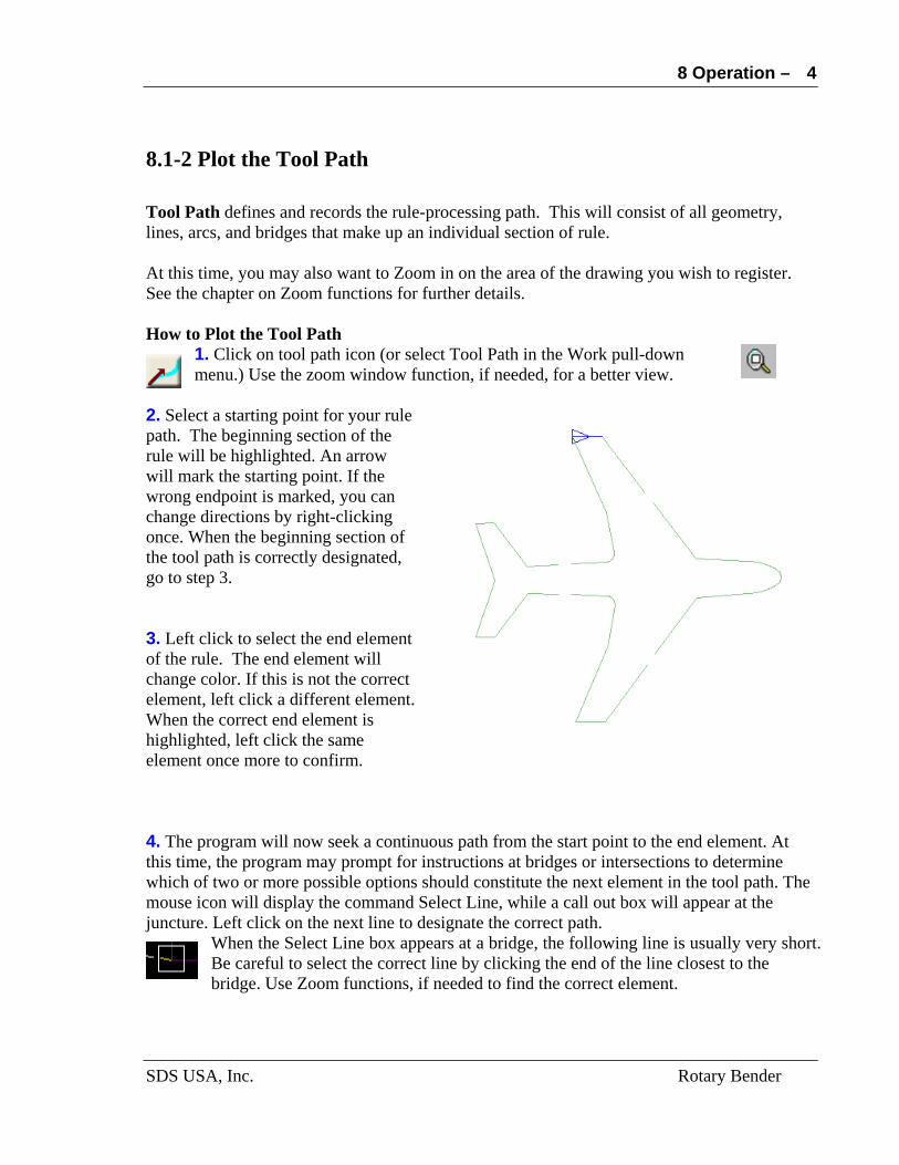
8.1-2 Plot the Tool Path Tool Path defines and records the rule-processing path. This will consist of all geometry, lines, arcs, and bridges that make up an individual section of rule. At this time, you may also want to Zoom in on the area of the drawing you wish to register. See the chapter on Zoom functions for further details. How to Plot the Tool Path
1. Click on tool path icon (or select Tool Path in the Work pull-down menu.) Use the zoom window function, if needed, for a better view.
2. Select a starting point for your rule path. The beginning section of the rule will be highlighted. An arrow will mark the starting point. If the wrong endpoint is marked, you can change directions by right-clicking once. When the beginning section of the tool path is correctly designated, go to step 3. 3. Left click to select the end element of the rule. The end element will change color. If this is not the correct element, left click a different element. When the correct end element is highlighted, left click the same element once more to confirm. 4. The program will now seek a continuous path from the start point to the end element. At this time, the program may prompt for instructions at bridges or intersections to determine which of two or more possible options should constitute the next element in the tool path. The mouse icon will display the command Select Line, while a call out box will appear at the juncture. Left click on the next line to designate the correct path.
When the Select Line box appears at a bridge, the following line is usually very short. Be careful to select the correct line by clicking the end of the line closest to the bridge. Use Zoom functions, if needed to find the correct element.
SDS USA, Inc. Rotary Bender
8 Operation –
5
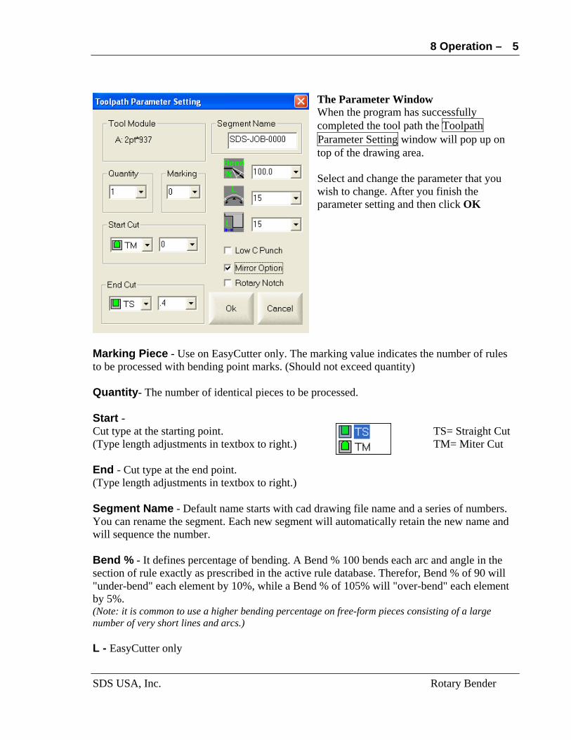
The Parameter Window When the program has successfully completed the tool path the Toolpath Parameter Setting window will pop up on top of the drawing area. Select and change the parameter that you wish to change. After you finish the parameter setting and then click OK
Marking Piece - Use on EasyCutter only. The marking value indicates the number of rules to be processed with bending point marks. (Should not exceed quantity) Quantity- The number of identical pieces to be processed. Start - Cut type at the starting point. TS= Straight Cut (Type length adjustments in textbox to right.) TM= Miter Cut End - Cut type at the end point. (Type length adjustments in textbox to right.) Segment Name - Default name starts with cad drawing file name and a series of numbers. You can rename the segment. Each new segment will automatically retain the new name and will sequence the number. Bend % - It defines percentage of bending. A Bend % 100 bends each arc and angle in the section of rule exactly as prescribed in the active rule database. Therefor, Bend % of 90 will "under-bend" each element by 10%, while a Bend % of 105% will "over-bend" each element by 5%. (Note: it is common to use a higher bending percentage on free-form pieces consisting of a large number of very short lines and arcs.) L - EasyCutter only
SDS USA, Inc. Rotary Bender
8 Operation –
6
Low C Punch - Chooses the lower of two punches of the same width. This corresponds to the index number in the tool parameters of the configuration menu. Mirror option - Check the box to produce a mirror image of the registered piece. Rotary Notch – Check the box to add relief notches when the plotted segment is off from the 90’. *By enabling vertical relief notch on Parameter 2, you could also add relief notches with vertical line. 8.1-3 Run the Tool Path The tool path can be run in a single mode (Run-Single) or a batch mode (Run-Batch). The Run-Single mode can process many rule pieces at once only in single tool path. The Run Batch mode is a group of Run-Single mode.
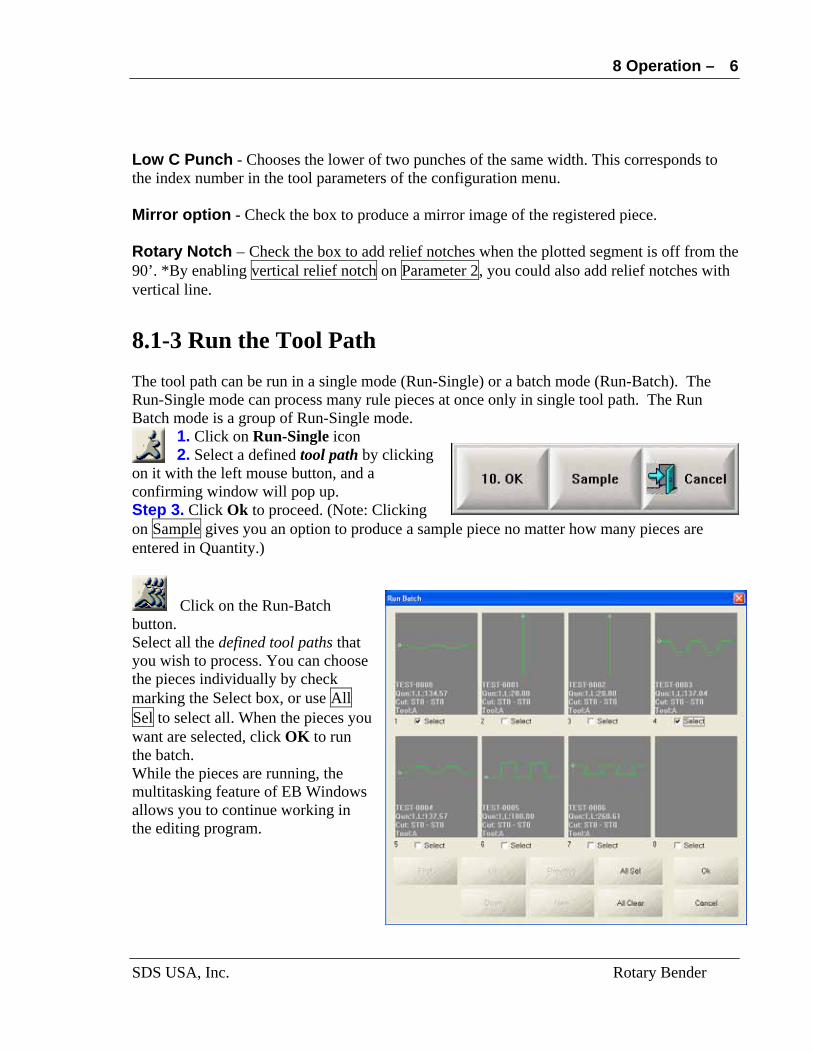
1. Click on Run-Single icon 2. Select a defined tool path by clicking
on it with the left mouse button, and a confirming window will pop up. Step 3. Click Ok to proceed. (Note: Clicking on Sample gives you an option to produce a sample piece no matter how many pieces are entered in Quantity.)
Click on the Run-Batch button. Select all the defined tool paths that you wish to process. You can choose the pieces individually by check marking the Select box, or use All Sel to select all. When the pieces you want are selected, click OK to run the batch. While the pieces are running, the multitasking feature of EB Windows allows you to continue working in the editing program.
SDS USA, Inc. Rotary Bender

8 Operation –
7
A powerful feature of Batch Mode is the ability to view all the pieces. They are displayed eight at a time, and you can quickly page through the entire segment file for your current job. In addition to the geometry of each section, Batch Mode displays the Segment Name, Quantity, Length, Start and End Cut Parameters, and Tool Module designation. This allows you to verify that each piece has been correctly registered before running it in batch mode. If certain sections of rule need to be modified, such as mirrored pieces in folding carton work, it is a simple matter to change parameters in Batch Mode. Simply click on the image of the piece that needs to be modified, and the Parameters Menu will appear. Make the necessary changes. Select the piece, and Run
HINT: The Windows operating system allows you to "capture" any screen, simply by pressing ALT + Print Screen at the same time. If you capture the pages of your Run Batch screen, paste them into document, and print them out, you can store them or provide them with the die as a handy reference guide for future repairs or re-rules. Note, however, that the length reflects
SDS USA, Inc. Rotary Bender

8 Operation –
SDS USA, Inc. Rotary Bender
8
the CAD drawing only, and does not include adjustment, elongation or additions or subtractions of length at each end of the rule.
8.1-4 Adjusting ANGLEs and ARCs Some pieces may require adjustment of individual arcs or angles. This can occur when a sharp bend or small radius is followed closely by another sharp bend or small radius. If both bends are in the same direction, the piece will under-bend. If the bends are in opposite directions, the piece will over-bend. If the geometry is too tight, there may be interference with the bending finger and/or nozzle. Occasionally, a length adjustment in one a section of rule may be required in order to properly fit the dieboard. The adjustment of angles and arcs are only in percentage mode. Length is added by entering a value. Length is subtracted by entering a minus sign, and the value.
1. Click the Adjust button, or select Edit / Adjust.
2. Select the Tool Path that needs adjustment.
The Adjust Pop-Up menu will appear at the top of your screen. Use your up or down arrow to scroll through the table until the correct section of rule is highlighted. As you scroll, the color of the corresponding arc or line will change, in order to help verify your choice. An angle is at the point where to lines meet. Moving from the start point of the section of rule, the line just past the angle is the line to select in order to change the bending percentage of the angle. (If you type in a radius in the Radius replacement textbox, and type in a percentage in the Percentage textbox, then select Replacement, the program will apply the percentage to all radii within a close tolerance of the radius entered.)

8 Operation –
9
3. Enter the changes. 4. Select Apply to save the changes and Exit to leave the Adjust menu. The diagrams below show the effect as adjust is applied to various arcs and angles. An Angle % of 120 a right angle will produce a sharp angle. An Arc% of 90 on a 180° radius will open the radius, by approximately 18° (+ or - a few degrees.) Added Length of 3 mm will lengthen the selected section by exactly 3mm.
SDS USA, Inc. Rotary Bender

8 Operation –
10
8.1-5 Saving Information Saving data on a regular basis is good programming practice.
The save icon applies ONLY to the original CAD file that was imported. It will save the file in the same directory and with the current file name and extension, which
appear in the bar at the very top of the screen. (Caution: The original version Simple Cad Editor only saves in DXF format. The file would be saved in mm and in DXF format regardless of the original scale, format or extension of the file. If you overwrite filename.CF2 file in DXF format, you will have to rename it filename.DXF to be able to open it again.) Saving the DXF file can be helpful if you have made changes, such as notch breaks, or if you have made repairs to the file that you would like to keep. If you do not want to overwrite the original CAD file, then use File, Save As and give it a new name or place it in a different directory. The Save As name and location will now become the current file name, and the Save icon can be used to save subsequent changes to the file. 8.1-6 Saving Tool path information. This feature allows you to save the tool path information on the segments that you have registered. There is no icon shortcut. You must select File / Fil File Save to save this information. A standard Windows Pop-Up menu will allow you to designate the name and location of your Tool Path Information. To retrieve the information, you will have to locate the file by name in the directory where it was saved. There is no preview option for Fil files. 8.2 Manual Operation
These functions have deal directly with the operation of the bender and the setting and running of Tool Paths. Because the work functions are the most commonly used,
the icon shortcuts are placed vertically along the left-hand side of the drawing area. The order and layout of these functions are specifically designed to make them easy for the first time users and experienced operators to find and use. This allows the operator to directly control the feed motor, puncher and bending functions of the EasyBender Turbo. The current tool module is displayed at the top left-hand corner of the pop-up menu. If the user has assigned a description of the tool in the text box in the configuration menu, i.e. "2pt Center Bevel" it will appear next to the module name.
SDS USA, Inc. Rotary Bender

8 Operation –
11
Just below the tool module name is a graphic representation of the tooling block. The first two figures represent the miters. The third figure is the straight cut, followed by the start and end miters. If you click on one of these, it will directly drive the puncher. This is a good tool for diagnostics, for clearing jams, etc. Caution: Careless operation of the puncher can cause rule jams. In the lower left of puncher icons, there are three more icons representing. The first and second icons will rotate the bending assembly 50 pulses counter-clockwise or clockwise respectively. The third icon is only for Rotary Bender. Below of Manual Operation are bending overrides. These features are used for locating the bending center of the rule, (See chapter on calibration), and for performing diagnostics on the bending mechanisms. The Test Pulse dictates the pulse used in the centering test. The figure shown here (20000) would be adequate for 1.5 to 2 pt. Rule. For three and four point rule a higher test pulse will be needed in order to produce measurable test bends. The Left, Right, and Both buttons, located just below the test pulse will produce sample sections of rule. The Feedless Finder Move will cycle the Left and Right Fingers in a Dry Run Mode. Tool Module Display the current tool configuration Tool Puncher selector: straight cut, miter cut, and notch cut Manual Operation Activate gear, manual oil pumping for Rotary Bender Test Bend Make a sample bending pieces Finger Test Raise and lower the fingers Feedless Finger Move Operate finger without proceed the rule Bend Origin Reset the bending mechanism Rule Feed Enter the amount of length to feed the rule forward (unit: mm) Finger Test Buttons, in the center of the screen, will raise and lower the fingers. The Original Pulse text box is where you type corrections for the bending center of the rule after you have run you left and right test bends. Some versions of the software will only allow
SDS USA, Inc. Rotary Bender
8 Operation –
12
you to type in numeric characters. To type in a negative number, type in the number as a positive integer, then backspace to the beginning and insert the minus sign. Take note of the bending center in case you have to re-enter this information directly into the Configuration screen. 8.3 Emergency Stop and Reset the Machine.
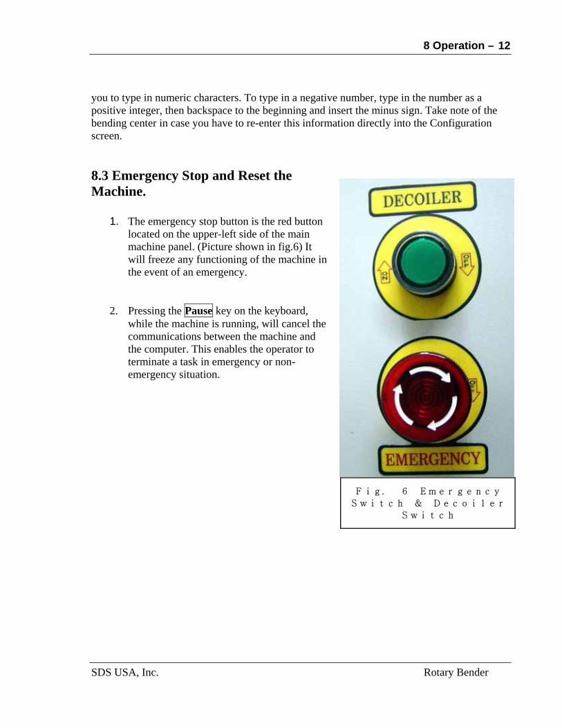
Fig. 6 Emergency
Switch & Decoiler
Switch
1. The emergency stop button is the red button
located on the upper-left side of the main machine panel. (Picture shown in fig.6) It will freeze any functioning of the machine in the event of an emergency.
2. Pressing the Pause key on the keyboard,
while the machine is running, will cancel the communications between the machine and the computer. This enables the operator to terminate a task in emergency or non-emergency situation.
SDS USA, Inc. Rotary Bender