systems in motion - vahle · systems in motion 4c/de 2015 enclosed conductor system mkh 4c/en 2016....
TRANSCRIPT

MACHT STROM MOBILMACHT STROM MOBIL
SYSTEMS IN MOTION
4c/de 2015
Enclosed Conductor SystemMKH
4c/en 2016

22
Description of the conductor system
The MKH… is a totally enclosed conductor system for indoor and outdoor use. The insulated housing can accommodate different copper sections.Type MKHD in 6 to 10 copper conductor version, continuous copper strips 40 - 160 A (copper strips come as separate items as coils).Type MKHF in 6- and 8-conductor version, with preassembled copper conductors and spring loaded connectors from 40 to 100 A.Type MKHS in 6- and 8-conductor version, with preassembled copper conductors and bolted joints from 40 to 200 A.A compact design, corrosion resistance and easy installation arethe main characteristics.
The MKH complies with VDE, european and international standards as well as accident prevention regulations. It is protected to IP 23 standards.The MKH can be supplied with sealing strip and heating system.With sealing strip it is protected to IP 24 standards and EN 60529 (0470, part 1) regulation.Collectors are safe against touch only when fully entered into the conductor system.If there is the possibility to touch live parts by hand, ie. collectors that might leave the powerail during operation, provide safety barrier or disconnect mains. This is valid only for a supply voltage exceeding 24 V AC or 60 V DC. Other cross sections, as indicated on page 3, are possible.If a conductor is used as N please note VDE 0100 part 430.
Low voltages of max. 50 V AC or 120 V DC are valid if the conductor system is only used as control line (type…SSD). Refer to regulation SELV or PELV (also DIN VDE 0100-410). A ground conductor is required for higher voltages.
Enclosed conductor system MKH
ContentDescription of the conductor system .............................................. 3Technical Data ............................................................................... 5Technicall data & standard sections ............................................... 6Types & order numbers .................................................................. 7Sections & Sealing strips ............................................................... 9Hangers & end sections ............................................................... 10Brackets...................................................................................... 11Jointing material & End feeds ....................................................... 12Line feeds ................................................................................... 13Heating ....................................................................................... 17Contact sections, Turntables and Switches ................................... 19Entry funnel ................................................................................ 20Transfer guides ........................................................................... 21
Removal sections ........................................................................ 23Maintenance Sections ................................................................. 24Conductor dead sections ............................................................. 25Anti-condensation sections ......................................................... 26Expansion Sections ..................................................................... 27Collectors .................................................................................... 29Tow arms .................................................................................... 32Flat copper .................................................................................. 33Cable glands ............................................................................... 33Assembling tools ........................................................................ 34Example for ordering ................................................................... 35Spare parts ................................................................................. 36Questionnaire ............................................................................. 39
333
In case of special environmental conditions the PVC – housing can be equipped with stainless steel conductors (refer to page 33). Please send detailed information. For low voltage applications please consult our factory.
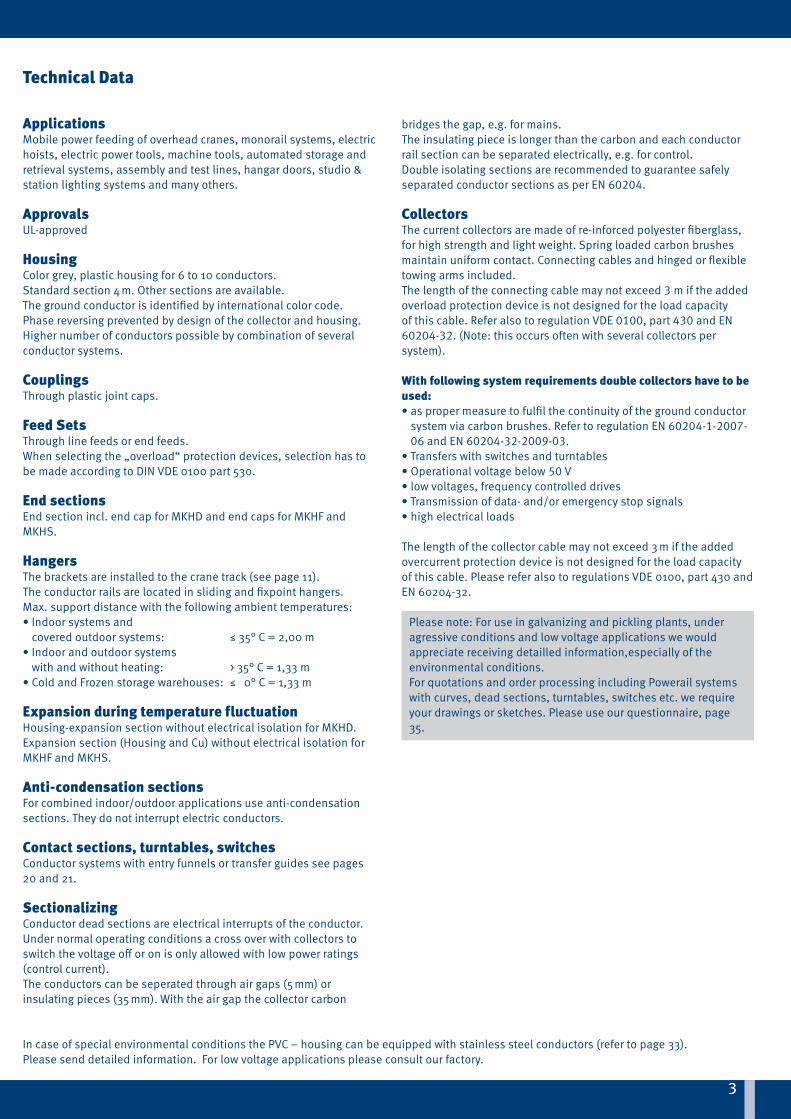
Technical Data
ApplicationsMobile power feeding of overhead cranes, monorail systems, electric hoists, electric power tools, machine tools, automated storage and retrieval systems, assembly and test lines, hangar doors, studio & station lighting systems and many others.
ApprovalsUL-approved
HousingColor grey, plastic housing for 6 to 10 conductors.Standard section 4 m. Other sections are available.The ground conductor is identified by international color code.Phase reversing prevented by design of the collector and housing.Higher number of conductors possible by combination of severalconductor systems.
Couplings Through plastic joint caps.
Feed Sets Through line feeds or end feeds. When selecting the „overload“ protection devices, selection has to be made according to DIN VDE 0100 part 530.
End sectionsEnd section incl. end cap for MKHD and end caps for MKHF and MKHS.
HangersThe brackets are installed to the crane track (see page 11).The conductor rails are located in sliding and fixpoint hangers.Max. support distance with the following ambient temperatures:• Indoor systems and
covered outdoor systems: ≤ 35° C = 2,00 m• Indoor and outdoor systems
with and without heating: > 35° C = 1,33 m• Cold and Frozen storage warehouses: ≤ 0° C = 1,33 m
Expansion during temperature fluctuationHousing-expansion section without electrical isolation for MKHD.Expansion section (Housing and Cu) without electrical isolation for MKHF and MKHS.
Anti-condensation sectionsFor combined indoor/outdoor applications use anti-condensationsections. They do not interrupt electric conductors.
Contact sections, turntables, switchesConductor systems with entry funnels or transfer guides see pages 20 and 21.
SectionalizingConductor dead sections are electrical interrupts of the conductor. Under normal operating conditions a cross over with collectors to switch the voltage off or on is only allowed with low power ratings (control current).The conductors can be seperated through air gaps (5 mm) or insulating pieces (35 mm). With the air gap the collector carbon
bridges the gap, e.g. for mains.The insulating piece is longer than the carbon and each conductor rail section can be separated electrically, e.g. for control.Double isolating sections are recommended to guarantee safely separated conductor sections as per EN 60204.
CollectorsThe current collectors are made of re-inforced polyester fiberglass, for high strength and light weight. Spring loaded carbon brushes maintain uniform contact. Connecting cables and hinged or flexible towing arms included.The length of the connecting cable may not exceed 3 m if the added overload protection device is not designed for the load capacity of this cable. Refer also to regulation VDE 0100, part 430 and EN 60204-32. (Note: this occurs often with several collectors per system).
With following system requirements double collectors have to be used: • as proper measure to fulfil the continuity of the ground conductor
system via carbon brushes. Refer to regulation EN 60204-1-2007-06 and EN 60204-32-2009-03.
• Transfers with switches and turntables • Operational voltage below 50 V• low voltages, frequency controlled drives • Transmission of data- and/or emergency stop signals • high electrical loads
The length of the collector cable may not exceed 3 m if the added overcurrent protection device is not designed for the load capacity of this cable. Please refer also to regulations VDE 0100, part 430 and EN 60204-32.
Please note: For use in galvanizing and pickling plants, under agressive conditions and low voltage applications we would appreciate receiving detailled information,especially of the environmental conditions.For quotations and order processing including Powerail systems with curves, dead sections, turntables, switches etc. we require your drawings or sketches. Please use our questionnaire, page 35.

44
Electrical properties
Mechanical properties
Max. continuous current Nominal voltage (UL)
Dielectric strength Spec. resistance Surface resistance Leakage resistance
200 A (with 80 % duty cycle)
690 V (600 V) IEC 60243 30-40 KV/mm
IEC 600935 x 1015 Ω/cm
IEC 60093 1013 Ω EN 60112 CTI 400-2,7
Flexible strength Tensile strength
Temperature range (ambient):
Combustibility Resistance to chemicals (at + 45 °C)
75 N/mm2 ± 10 % 40 N/mm2 ± 10 - 30 °C bis + 60 °C flame retardant DIN 41 02 - Klasse B 1; self extinguishing
Gasoline, Mineral Oil, Grease, Sulphuric acid 50 %, Caustic soda 25 % and 50 %Hydro-chloric acid, concentrated
Technical Data
Ambient temperature °C 35 °C 40 °C 45 °C 50 °C 55 °C 60 °C
Correction factor ƒTStandard shrouding
1 0,95 0,89 0,84 0,77 0,71
Correction factor ƒT
Voltage drop for the conductor
Permissible continuous current of the conductor
For three-phase current
For alternating current
For direct current
ΔU = √3 · I · IA · Z
IDzul.UT = Izul. x ƒT[A] with IDzul.UT > IDA
ΔU = 2 · I · IA · Z
ΔU = 2 · I · IA · R
Z = impedance [Ώ/km]R = resistance [Ώ/km]I = feed length [km]IA = inrush current of installation in amperes
Izul. = Permissible continuous current of the conductor at 35°C (catalogue value) (A)
ƒT = Correction factor

55
L1
3 (7)
(3)
MKH7 poles
L3(6)
1(2)
2(5)
L2(1) (4)
L1
3 (7) 4 (8)
(3)
MKH8 poles
L3(6)
1(2)
2(5)
L2(1) (4)
L1(3)
MKH6 poles
L3(6)
1(2)
2(5)
L2(1) (4)
Type(2)
(HS with PE SS without PE)
No. ofcon-ductors
Copper cross section mm2 Ampere rating with 35 °C in A, L1, L2, L3(5)
No-minal voltage V(4)
Impedance at 50 Hz 20 °C Ώ/1000 m
Resistance at 20 °C Ώ/1000 m
Leakage distance mm
PhaseL1, L2, L3
Control-line 60 % DC
80 % DC
100 % DC
PhaseL1, L2, L3
PhaseL1, L2, L3
MKH...6/63-HSC 6 3 x 10 10 2 x 10 81 70 63 690 1,731 1,731 1,717 1,717 30
MKH...6/63-SSD 6 6 x 10 81 70 63 690 1,731 1,717 30
MKH...6/80-HSC 6 3 x 17 17 2 x 10 103 89 80 690 1,078 1,078 1,057 1,057 30
MKH...6/100-HSC 6 3 x 26 26 2 x 10 129 112 100 690 0,717 0,717 0,687 0,687 30
MKH...6/140-HSC 6 3 x 33 26 2 x 10 161 140 125 690 0,586 0,717 0,549 0,687 30
MKH...6/160-HSC 6 3 x 42 26 2 x 10 184 160 143 690 0,473 0,717 0,429 0,687 30
MKH...6/200-HSC(3) 6 3 x 51 26 2 x 10 231 200 179 690 0,393 0,717 0,344 0,687 30
MKH...7/63-HSC 7 3 x 10 10 2 x 10 1 x 11 81 70 63 690 1,731 1,731 1,717 1,717 30
MKH...7/63-SSD 7 6 x 10 1 x 11 81 70 63 690 1,731 1,717 30
MKH...7/80-HSC 7 3 x 17 17 2 x 10 1 x 11 103 89 80 690 1,078 1,078 1,057 1,057 30
MKH...7/100-HSC 7 3 x 26 26 2 x 10 1 x 11 129 112 100 690 0,717 0,717 0,687 0,687 30
MKH...7/140-HSC 7 3 x 33 26 2 x 10 1 x 11 161 140 125 690 0,586 0,717 0,549 0,687 30
MKH...7/160-HSC 7 3 x 42 26 2 x 10 1 x 11 184 160 143 690 0,473 0,717 0,429 0,687 30
MKH...7/200-HSC(3) 7 3 x 51 26 2 x 10 1 x 11 231 200 179 690 0,393 0,717 0,344 0,687 30
MKH...8/63-HSC 8 3 x 10 10 2 x 10 2 x 11 81 70 63 690 1,731 1,731 1,717 1,717 30
MKH...8/63-SSD 8 6 x 10 2 x 11 81 70 63 690 1,731 1,717 30
MKH...8/80-HSC 8 3 x 17 17 2 x 10 2 x 11 103 89 80 690 1,078 1,078 1,057 1,057 30
MKH...8/100-HSC 8 3 x 26 26 2 x 10 2 x 11 129 112 100 690 0,717 0,717 0,687 0,687 30
MKH...8/140-HSC 8 3 x 33 26 2 x 10 2 x 11 161 140 125 690 0,586 0,717 0,549 0,687 30
MKH...8/160-HSC 8 3 x 42 26 2 x 10 2 x 11 184 160 143 690 0,473 0,717 0,429 0,687 30
MKH...8/200-HSC(3) 8 3 x 51 26 2 x 10 2 x 11 231 200 179 690 0,393 0,717 0,344 0,687 30
Technical Data
Cross sections:(1)
In case of using a neutral conductor copper pos.1 will be taken.Layout of the system on request. (See page 5)
(1) Numbers in paranthesis apply to control line(2) Complete types e.g. MKHS 7/63 HS for 7 poles with bolted joints (3) only for MKHS (4) Nominal voltage UL = 600 V(5) Power consumption UL on request

6
MKHD/MKHF/MKHS
6
left side
right side
A
AStandard section e.g. 4 m
MKHD/MKHF/MKHS
left side
right side
A
A
Standard section e.g. 4 m
left side
right side
A
A
Standard section e.g. 4 m
3 (7) 4 (8)
(3)
MKH9 poles
L3(6)
1(2)
2(5)
L2(1) (4)
L1
9 (9)
L1(3)
3 (7) 4 (8)
MKH10 poles
L3(6)
1(2)
2(5)
L2(1)
10 (10) 9 (9)
(4)
L1(3)
MKHe.g. 6 poles
L3(6)
1(2)
2(5)
L2(1) (4)
56,2A - A
88
safety-web
yellow(dark grey)
green(dark grey)
Type(2)
(HS with PE SS without PE)
No. ofcon-duc-tors
Copper cross section mm2 Ampere rating with 35 °C in A, L1, L2, L3(3)
No-minal voltage V
Impedance at 50 Hz 20 °C Ώ/1000 m
Resistance at 20 °C Ώ/1000 m
Leakage dis-tance mmPhase
L1, L2, L3
Control-line 60% DC
80% DC
100% DC
PhaseL1, L2, L3
PhaseL1, L2, L3
MKHD...9/63-HSC 9 3 x 10 10 2 x 10 3 x 11 81 70 63 690 1,731 1,731 1,717 1,717 30
MKHD...9/63-SSD 9 6 x 10 3 x 11 81 70 63 690 1,731 1,717 30
MKHD...9/80-HSC 9 3 x 17 17 2 x 10 3 x 11 103 89 80 690 1,078 1,078 1,057 1,057 30
MKHD...9/100-HSC 9 3 x 26 26 2 x 10 3 x 11 129 112 100 690 0,717 0,717 0,687 0,687 30
MKHD...9/140-HSC 9 3 x 33 26 2 x 10 3 x 11 161 140 125 690 0,586 0,717 0,549 0,687 30
MKHD...9/160-HSC 9 3 x 42 26 2 x 10 3 x 11 184 160 143 690 0,473 0,717 0,429 0,687 30
MKHD...10/63-HSC 10 3 x 10 10 2 x 10 4 x 11 81 70 63 690 1,731 1,731 1,717 1,717 30
MKHD...10/63-SSD 10 6 x 10 4 x 11 81 70 63 690 1,731 1,717 30
MKHD...10/63-HSC 10 3 x 17 17 2 x 10 4 x 11 103 89 80 690 1,078 1,078 1,057 1,057 30
MKHD...10/100-HSC 10 3 x 26 26 2 x 10 4 x 11 129 112 100 690 0,717 0,717 0,687 0,687 30
MKHD...10/140-HSC 10 3 x 33 26 2 x 10 4 x 11 161 140 125 690 0,586 0,717 0,549 0,687 30
MKHD...10/160-HSC 10 3 x 42 26 2 x 10 4 x 11 184 160 143 690 0,473 0,717 0,429 0,687 30
(1) Numbers in paranthesis apply to control line(2) Nominal voltage UL = 600 V(3) Power consumption UL on request
Technical data & standard sections
Type MKHF with plug-in joints, factory assembled
Type MKHS with bolted joints, factory assembled
Cross sections:(1)
In case of using a neutral conductor copper pos.1 will be taken.Layout of the system on request.
Pole 9 and 10 for max. 24 V AC or 60 V DC
Standard sections
Type MKHD for continuous copper strips

77
MKHD/MKHF
Type(1) Weight kg/m Order-No.
MKHD-....HSC 1,052 262 50•
MKHD-....SSD 1,052 262 51•
Type(1) Weight kg/m Order-No.
MKHF6/63-....HSC 1,638 263 20•
MKHF6/63-....SSD 1,638 263 22•
MKHF6/80-....HSC 1,839 263 21•
MKHF6/100-....HSC 2,176 262 05•
MKHF7/63-....HSC 1,748 263 23•
MKHF7/63-....SSD 1,748 263 25•
MKHF7/80-....HSC 1,949 263 24•
MKHF7/100-....HSC 2,277 262 09•
MKHF8/63-....HSC 1,858 263 26•
MKHF8/63-....SSD 1,858 263 28•
MKHF8/80-....HSC 2,059 263 27•
MKHF8/100-....HSC 2,387 262 13•
Types & order numbers
Type MKHDwith continuous copper strips,to be drawn in during installation.
Type MKHFwith factory assembled copper stripsand plug-in joints (40 – 100 A)
(1) Complete types e.g. MKHD-4000HSC or 4 m with PE, Order-No. 262 504MKHF8/63-4000HSC for 4 m with PE, Order-No. 263 264 The 4-digit number (in bold) in the type indicates the length of the section in mm.
• The last number of the order specifi es the section length. Please suffi x the order number with 1, 2, 3, 4.

88
Types & order numbers
Type(1) Weight kg/m Order - No.
MKHS6/63-....HSC 1,824 263 29•
MKHS6/63-....SSD 1,824 263 31•
MKHS6/80-....HSC 1,950 263 30•
MKHS6/100-....HSC 2,353 262 20•
MKHS6/140-....HSC 2,530 262 21•
MKHS6/160-....HSC 2,773 262 22•
MKHS6/200-....HSC 3,019 262 23•
MKHS7/63-....HSC 1,961 263 32•
MKHS7/63-....SSD 1,961 263 34•
MKHS7/80-....HSC 2,087 263 33•
MKHS7/100-....HSC 2,490 262 27•
MKHS7/140-....HSC 2,667 262 28•
MKHS7/160-....HSC 2,910 262 29•
MKHS7/200-....HSC 3,156 262 30•
MKHS8/63-....HSC 2,098 263 35•
MKHS8/63-....SSD 2,098 263 37•
MKHS8/80-....HSC 2,224 263 36•
MKHS8/100-....HSC 2,627 262 34•
MKHS8/140-....HSC 2,804 262 35•
MKHS8/160-....HSC 3,047 262 36•
MKHS8/200-....HSC 3,293 262 37•
MKHS
Type MKHSwith factory assembled copper stripsand bolted joints (40 - 200 A)
(1) Complete types e.g. MKHS8/63-4000HSC for 4 m with PE, Order-No. 262 324The 4-digit number (in bold) in the type indicates the length of the section in mm.
• The last number of the order specifi es the section length. Please suffi x the order number with 1, 2, 3, 4.
99
L1(3)
L3(6)
1(2)
2(5)
L2(1) (4)
safety-web
yellow(dark grey)
green(dark grey)
VRU
VRO
Bearing surfaceof the collector
HR for SA HR for SI
MKHe.g. 6 poles
L1
3 (7)
56,2
(3)
MKHe.g. 8 poles
L3
4 (8)
(6)
1(2)
2
88
appr
ox. 1
05
(5)
L2(1) (4)
2 sealing strips
MKHD/MKHF/MKHS
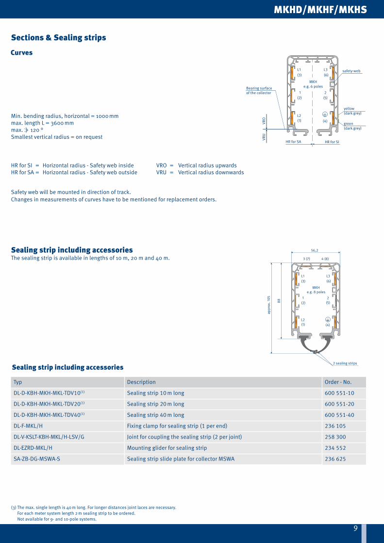
Curves
Typ Description Order - No.
DL-D-KBH-MKH-MKL-TDV10(1) Sealing strip 10 m long 600 551-10
DL-D-KBH-MKH-MKL-TDV20(1) Sealing strip 20 m long 600 551-20
DL-D-KBH-MKH-MKL-TDV40(1) Sealing strip 40 m long 600 551-40
DL-F-MKL/H Fixing clamp for sealing strip (1 per end) 236 105
DL-V-KSLT-KBH-MKL/H-LSV/G Joint for coupling the sealing strip (2 per joint) 258 300
DL-EZRD-MKL/H Mounting glider for sealing strip 234 552
SA-ZB-DG-MSWA-S Sealing strip slide plate for collector MSWA 236 625
Sections & Sealing strips
Min. bending radius, horizontal = 1000 mmmax. length L = 3600 mmmax. ) 120 °Smallest vertical radius = on request
Sealing strip including accessories
(3) The max. single length is 40 m long. For longer distances joint laces are necessary. For each meter system length 2 m sealing strip to be ordered. Not available for 9- and 10-pole systems.
HR for SI = Horizontal radius - Safety web inside VRO = Vertical radius upwardsHR for SA = Horizontal radius - Safety web outside VRU = Vertical radius downwards
Safety web will be mounted in direction of track.Changes in measurements of curves have to be mentioned for replacement orders.
Sealing strip including accessories The sealing strip is available in lengths of 10 m, 20 m and 40 m.

1010
6035
appr
ox. 1
56
appr
ox. 9
7
6035
appr
ox. 1
56ap
prox
. 101
90
167
110
23
100
300empty housing
MKHD/MKHF/MKHS
(1) stainless steel
Typ Weight kg Order - No.
AH-MGH 0,134 262 000
AH-MGH/K(1) 0,134 262 003
Typ Weight kg Order - No.
AH-MFH 0,182 262 001
AH-MFH/K(1) 0,182 262 002
Festaufhängung
Typ Weight kg Ausführung Order - No.
EK-MHED/L 0,401 left 262 537
EK-MHED/R 0,401 right 262 536
Type Weight kg Execution Order - No.
EK-MSES 0,308 left and right 235 141
Hangers & end sections
Sliding hanger
Fixpoint hanger
End section (MKHD)0,3 m long
End cap (MKHF / MKHS)

1111
MKHD/MKHF/MKHS
32
max
. 3730
LA
A
fixing claw45
D
25M8
support bracket
88 139
192
19+
6- 1
5+ 6
- 15
Tow arm level
X
B
R = 10 x DD
A
LX
B
D
4532
30
max
. 48
A
25
M8
support bracket
88 139
192
19+
6- 1
5+ 6
- 15
Tow arm level
R = 10 x DD
D
small fixing claw
ø 9
(1) e.g. HK-EHK250-KS12 → Order-No. 251720-12 for fixing claw with D=12mmSelect next larger size bracket when your -beam dimension B is more than 170 mm.
Type(1) X mm L mm B max mm Weight kg Order - No.
Standard version
with small fixing claw(1)
HK-EHK250-NS 250 350 170 1,080 251 600 -
HK-EHK250-KS... - 251 720-...
HK-EHK300-NS 300 400 170 1,128 251 610 -
HK-EHK300-KS... - 251 730-...
HK-EHK400-NS 400 500 170 1,266 251 620 -
HK-EHK400-KS... - 251 740-...
HK-EHK500-NS 500 600 170 1,394 251 630 -
HK-EHK500-KS... - 251 750-...
HK-EHK600-NS 600 700 170 1,561 251 640 -
HK-EHK600-KS... - 251 760-...
HK-EHK700-NS 700 800 170 1,761 251 650 -
HK-EHK700-KS... - 251 770-...
HK-EHK750-NS 750 850 170 1,782 251 660 -
HK-EHK750-KS... - 251 780-...
HK-EHK800-NS 800 900 170 1,936 251 670 -
HK-EHK800-KS... - 251 790-...
Brackets
view without - beam
Arrangement EHK with small fixing clawAttention! Make sure that hoist wheels have enough clearance.Use small claw if necessary.
- rail of EHK is identical to type S1, Cat. 8 a
Position of the fixing claw for D = 6-15 mm Position of the fixing claw for D = 15-25 mm

1212
92
150
20
100
167
23
23
167110
100
100
196
156
4023
167
110
100
Type Weight kg Order - No.
VM-MVMD 0,160 234 678
Type Weight kg Order - No.
VM-MVMS 0,274 234 585
Stoßabdeckkappe, klipsbar (MKHF / MKHS)
Type Weight kg Cable gland(Dimensions see p. 33)
Order - No.
ES-MKES6-8/63-80HS 0,492 M 25 and M 40 235 230
ES-MKES6-8/63SS 0,446 M 25 235 233
Type Weight kg Cable gland(Dimensions see p. 33)
Order - No.
ES-MKED6-8/63-80HS 0,515 M 25 and M 40 235 152
ES-MKED9-10/63-80HS 1,071 M 25 and M 40 262 538
ES-MKED6-8/63SS 0,470 M 25 235 157
ES-MKED9-10/63SS 1,020 M 25 262 539
MKHD/MKHF/MKHS
Jointing material & End feeds
Joint cap, self locking (MKHD)
Joint cap, self locking (MKHF / MKHS)
End feed (MKHF / MKHS)End feed comes loose without powerail section.It can be mounted at the left or right hand side.
Electrical connection with customer supplied cable shoes to M6 terminals.
End feed (MKHD)End feed comes loose without powerail section.It can be mounted at the left or right hand side.
Electrical connection with customer supplied cable shoes to M6 terminals.
6 - 8 poles 9 - 10 poles

1313
300 150
83
1000
MKHD
Type Weight kg Cable gland(Dimensions see p. 33)
Order - No.
ES-MHGD6/63-100HSC-1000 2,445 M 50 and M 25 262 545
ES-MHGD7/63-100HSC-1000 2,530 M 50 and M 25 262 546
ES-MHGD8/63-100HSC-1000 2,615 M 50 and M 25 262 547
ES-MHGD9/63-100HSC-1000 2,654 M 50 and M 25 262 548
ES-MHGD10/63-100HSC-1000 2,693 M 50 and M 25 262 549
ES-MHGD6/140-160HSC-1000 2,431 M 50 and M 25 262 550
ES-MHGD7/140-160HSC-1000 2,516 M 50 and M 25 262 551
ES-MHGD8/140-160HSC-1000 2,601 M 50 and M 25 262 552
ES-MHGD9/140-160HSC-1000 2,640 M 50 and M 25 262 553
ES-MHGD10/140-160HSC-1000 2,679 M 50 and M 25 262 554
ES-MHGD6/63SSD-1000 2,385 M 25 262 540
ES-MHGD7/63SSD-1000 2,460 M 25 262 541
ES-MHGD8/63SSD-1000 2,545 M 25 262 542
ES-MHGD9/63SSD-1000 2,584 M 25 262 543
ES-MHGD10/63SSD-1000 2,623 M 25 262 544
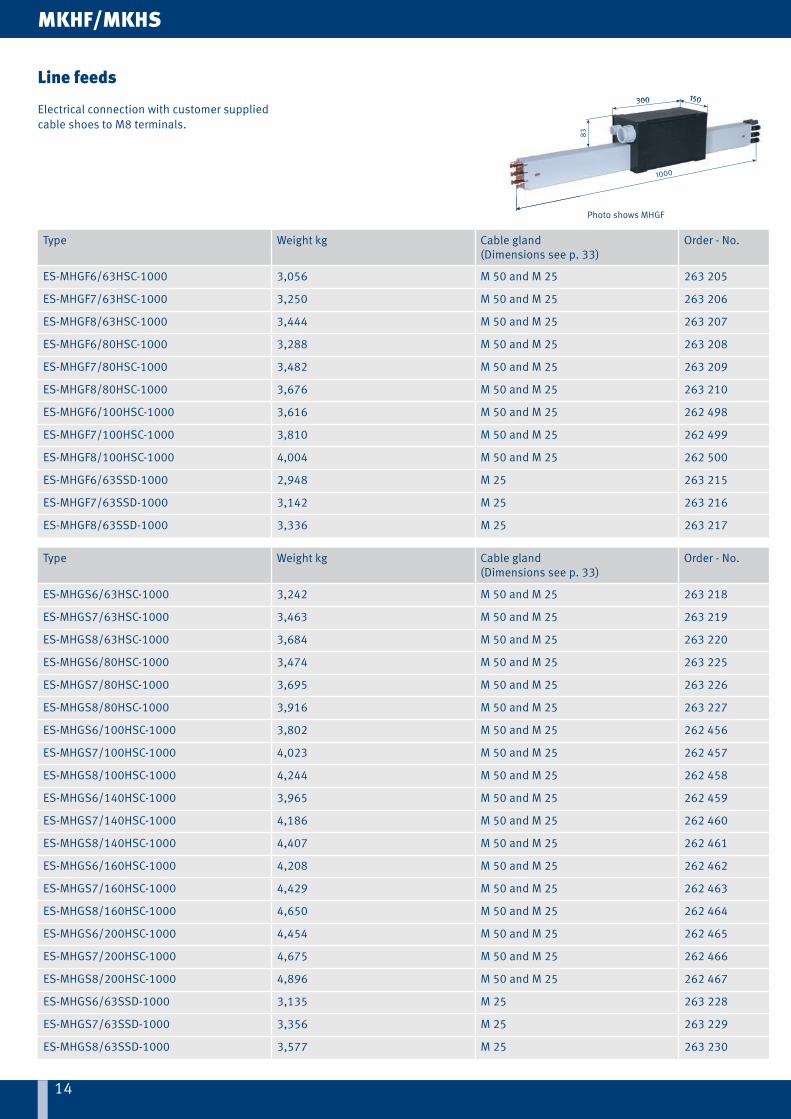
Line feeds
Electrical connection with customer supplied cable shoes to M8 terminals.
14
300 150
83
1000
14
300 150
83
1000
Photo shows MHGF
Type Weight kg Cable gland(Dimensions see p. 33)
Order - No.
ES-MHGF6/63HSC-1000 3,056 M 50 and M 25 263 205
ES-MHGF7/63HSC-1000 3,250 M 50 and M 25 263 206
ES-MHGF8/63HSC-1000 3,444 M 50 and M 25 263 207
ES-MHGF6/80HSC-1000 3,288 M 50 and M 25 263 208
ES-MHGF7/80HSC-1000 3,482 M 50 and M 25 263 209
ES-MHGF8/80HSC-1000 3,676 M 50 and M 25 263 210
ES-MHGF6/100HSC-1000 3,616 M 50 and M 25 262 498
ES-MHGF7/100HSC-1000 3,810 M 50 and M 25 262 499
ES-MHGF8/100HSC-1000 4,004 M 50 and M 25 262 500
ES-MHGF6/63SSD-1000 2,948 M 25 263 215
ES-MHGF7/63SSD-1000 3,142 M 25 263 216
ES-MHGF8/63SSD-1000 3,336 M 25 263 217
Type Weight kg Cable gland(Dimensions see p. 33)
Order - No.
ES-MHGS6/63HSC-1000 3,242 M 50 and M 25 263 218
ES-MHGS7/63HSC-1000 3,463 M 50 and M 25 263 219
ES-MHGS8/63HSC-1000 3,684 M 50 and M 25 263 220
ES-MHGS6/80HSC-1000 3,474 M 50 and M 25 263 225
ES-MHGS7/80HSC-1000 3,695 M 50 and M 25 263 226
ES-MHGS8/80HSC-1000 3,916 M 50 and M 25 263 227
ES-MHGS6/100HSC-1000 3,802 M 50 and M 25 262 456
ES-MHGS7/100HSC-1000 4,023 M 50 and M 25 262 457
ES-MHGS8/100HSC-1000 4,244 M 50 and M 25 262 458
ES-MHGS6/140HSC-1000 3,965 M 50 and M 25 262 459
ES-MHGS7/140HSC-1000 4,186 M 50 and M 25 262 460
ES-MHGS8/140HSC-1000 4,407 M 50 and M 25 262 461
ES-MHGS6/160HSC-1000 4,208 M 50 and M 25 262 462
ES-MHGS7/160HSC-1000 4,429 M 50 and M 25 262 463
ES-MHGS8/160HSC-1000 4,650 M 50 and M 25 262 464
ES-MHGS6/200HSC-1000 4,454 M 50 and M 25 262 465
ES-MHGS7/200HSC-1000 4,675 M 50 and M 25 262 466
ES-MHGS8/200HSC-1000 4,896 M 50 and M 25 262 467
ES-MHGS6/63SSD-1000 3,135 M 25 263 228
ES-MHGS7/63SSD-1000 3,356 M 25 263 229
ES-MHGS8/63SSD-1000 3,577 M 25 263 230
MKHF/MKHS
Line feeds
Electrical connection with customer supplied cable shoes to M8 terminals.

15
300 150
50,5
1000
15
300 150
50,5
1000
MKHD
Typ Weight kg Cable gland(Dimensions see p. 33)
Order - No.
ES-MHLD6/63-100HSC-1000-0 2,565 M 25 for L1, L2, L3
M 25 for 1 - 4
M 20 for PE, 9/10
262 560
ES-MHLD7/63-100HSC-1000-0 2,651 262 561
ES-MHLD8/63-100HSC-1000-0 2,737 262 562
ES-MHLD9/63-100HSC-1000-0 2,745 262 563
ES-MHLD10/63-100HSC-1000-0 2,749 262 564
ES-MHLD6/140-160HSC-1000-0 2,553 M 25 for L1, L2, L3
M 25 for 1 - 4
M 20 for PE, 9/10
262 565
ES-MHLD7/140-160HSC-1000-0 2,639 262 566
ES-MHLD8/140-160HSC-1000-0 2,725 262 567
ES-MHLD9/140-160HSC-1000-0 2,733 262 568
ES-MHLD10/140-160HSC-1000-0 2,737 262 569
ES-MHLD6/63SSD-1000-0 2,517 1 x M 25 262 555
ES-MHLD7/63SSD-1000-0 2,593 262 556
ES-MHLD8/63SSD-1000-0 2,679 262 557
ES-MHLD9/63SSD-1000-0 2,687 2 x M 25 262 558
ES-MHLD10/63SSD-1000-0 2,691 262 559
Line feeds
Electrical connection with customer supplied cable shoes to M8 terminals.

1616
51
300
1000
150
51
3
1000
Type Weight kg Cable gland(Dimensions see p. 33)
Order - No.
ES-MHLS6/63HSC-1000-0 3,356 M 25 for L1, L2, L3
M 25 for 1 - 4
M 20 for PE
263 248
ES-MHLS7/63HSC-1000-0 3,577 263 249
ES-MHLS8/63HSC-1000-0 3,798 263 250
ES-MHLS6/80HSC-1000-0 3,588 263 255
ES-MHLS7/80HSC-1000-0 3,809 263 256
ES-MHLS8/80HSC-1000-0 4,030 263 257
ES-MHLS6/100HSC-1000-0 3,916 262 524
ES-MHLS7/100HSC-1000-0 4,137 262 525
ES-MHLS8/100HSC-1000-0 4,358 262 526
ES-MHLS6/140HSC-1000-0 4,081 M 25 for PE, L1, L2, L3
M 25 for 1 - 4
262 527
ES-MHLS7/140HSC-1000-0 4,302 262 528
ES-MHLS8/140HSC-1000-0 4,523 262 529
ES-MHLS6/160HSC-1000-0 4,324 262 530
ES-MHLS7/160HSC-1000-0 4,545 262 531
ES-MHLS8/160HSC-1000-0 4,766 262 532
ES-MHLS6/200HSC-1000-0 4,570 262 533
ES-MHLS7/200HSC-1000-0 4,791 262 534
ES-MHLS8/200HSC-1000-0 5,012 262 535
ES-MHLS6/63SSD-1000-0 3,256 M 25 263 258
ES-MHLS7/63SSD-1000-0 3,477 263 259
ES-MHLS8/63SSD-1000-0 3,698 263 260
Type Weight kg Cable gland(Dimensions see p. 33)
Order - No.
ES-MHLF6/63HSC-1000-0 3,170 M 25 for L1, L2, L3
M 25 for 1 - 4
M 20 for PE
263 235
ES-MHLF7/63HSC-1000-0 3,364 263 236
ES-MHLF8/63HSC-1000-0 3,558 263 237
ES-MHLF6/80HSC-1000-0 3,402 263 238
ES-MHLF7/80HSC-1000-0 3,596 263 239
ES-MHLF8/80HSC-1000-0 3,790 263 240
ES-MHLF6/100HSC-1000-0 3,730 262 486
ES-MHLF7/100HSC-1000-0 3,924 262 487
ES-MHLF8/100HSC-1000-0 4,118 262 488
ES-MHLF6/63SSD-1000-0 3,075 M 25 263 245
ES-MHLF7/63SSD-1000-0 3,269 263 246
ES-MHLF8/63SSD-1000-0 3,463 263 247
MKHF/MKHS
Line feeds
Electrical connection with customer supplied cable shoes to M8 terminals.
Photo shows MHLS

17
(2)
17
MKHD/MKHF/MKHSN(W
/m)
18
20
22
24
26
28
25
30 40 50 60 70 80 90 100 110 120 130
l(m)
400V
18
20
22
24
26
28
25
30 40 50 60 70 80 90 100 110 120 130
N(W
/m)
l(m)
230V
H0.15
H0.2
H0.32
H0.38
H0.48
H0.6
H0.81
H1.0
H1.44
H2.0
H0.48
H0.6
H0.81
H1.44
H2.0
H3.0
H3.0
H1.0
Type Resistance(1) Order - No.
HL-0,10-EYCEX-5203-PTFE-260-750 0,10 Ω/m 196 381
HL-0,15-EYCEX-5203-PTFE-260-750 0,15 Ω/m 196 382
HL-0,20-EYCEX-5203-PTFE-260-750 0,20 Ω/m 196 383
HL-0,32-EYCEX-5203-PTFE-260-750 0,32 Ω/m 196 384
HL-0,38-EYCEX-5203-PTFE-260-750 0,38 Ω/m 196 385
HL-0,48-EYCEX-5203-PTFE-260-750 0,48 Ω/m 196 386
HL-0,60-EYCEX-5203-PTFE-260-750 0,60 Ω/m 196 387
HL-0,81-EYCEX-5203-PTFE-260-750 0,81 Ω/m 196 389
HL-1,00-EYCEX-5203-PTFE-260-750 1,00 Ω/m 196 390
HL-1,44-EYCEX-5203-PTFE-260-750 1,44 Ω/m 196 391
HL-2,00-EYCEX-5203-PTFE-260-750 2,00 Ω/m 196 392
HL-3,00-EYCEX-5203-PTFE-260-750 3,00 Ω/m 196 393
HL-4,00-EYCEX-5203-PTFE-260-750 4,00 Ω/m 196 394
HL-4,40-EYCEX-5203-PTFE-260-750 4,40 Ω/m 196 395
HL-5,16-EYCEX-5203-PTFE-260-750 5,16 Ω/m 196 396
HL-5,60-EYCEX-5203-PTFE-260-750 5,60 Ω/m 196 397(1) Abweichungen ± 2,5 %
Heating
We recommend a heating system for outdoor installations and installations in humid plants. The heating consists of arrangement two heating cables as per drawing.
Attention: Switch on heating system below + 5 °C ambient temperature.
The type of heating cable has to be calculated: heat output per heating cable between 20 - 25 W/m.
For longer heating distances the total length has to be devided into several heating sections.
For short heating distances to feed with lower secondary voltage via transformer.
Heating capacity [Watt/m]: N’ =U2
R ∧ L2
(2) Arrangement of heating cable
U = Supply voltage [Volt]R = Resistance of heating cable [Ohm/m]L = Lenght of heating section [m]
(1) ± 2,5 %
Heating cable

1818
MKHD/MKHF/MKHS
heating circuit 1 heating circuit 2
grid 230 or 400 VAC
grid 230 or 400 VAC
grid 230 or 400 VAC
1-core cable >2,5 mm2
installed by customer
Attention: max. 25 W/m per heating cable
TerminalBox
Type Design Cable gland(Dimensions see p. 33)
Order - No.
BH-AKB-MKH-L left end M 20 262 037
BH-AKB-MKH-R right end M 20 262 038
BH-AKB-MKH-M line feed 2 x M 20 262 039
BH-MA-KBH-MKL/H-LSV/G 1 set material for connecting clamps 195 291
Connecting boxes for heating
Heating
Schaltbeispiele (je nach Anlagensituation)
For each end feed box 2 sets of material for connecting ends are required.For line feed you need 4 sets of material for connection ends.
Order for 60 m conductor system (example)1) 122 m heating cable type H 2,0 (2 x 60 m and 2 x 1 m additional) Voltage 400 V, two heating circuits in parallel heating capacity as per above mentioned diagramm 2 x 22 W/m at 60 m 2 x 22 W/m ~2640 W = 2,64 kW.
2) 1x Junction box left end 1x Junction box right end
3) 4x sets of material for connection ends.
Switch gear assembly and temperature control unit as per customer's inquiry. Fuses, cables etc. have to be provided by the customer.

1919
w/o cond. (1) w/o cond.(1)
Line feed Powerail Track
w/o cond. (1) Contact area (1) w/o cond.
Transfer funnel
b
max. 20 mmLine feed
a
Track
Transfer guide, oblique cut Turntable frame
Powerail
aTransfer guide
Transfer guideLine feed
max. 20 mm
Transfer guide, oblique cut
Powerail
a
Track
Switch frame
R
c
α
Contact area
MKHD/MKHF/MKHS
Contact sections, Turntables and Switches
Please submit drawings of transfer applications.Specify dimensions a, b, c, R and angle α (α = max. 50° )Max. 20 mm air gap between transfer guides.
To create all components for contact sections, turntables and switches we require detailed construction drawings.
Contact section(1)
Turntable
Sliding switch
(1) Contact sections must not be activated before collectors are fully engaged.

2020
110
245w/o cond.(1)
B140 ± 10
500 at MKHF & MKHS525 at MKHD
245w/o cond.245
(1)
140 ± 10
500 at MKHF &
B
safety web
B
safety web
MKHD/MKHF/MKHS
Type(1) Weight kg Order - No. / Version
left right
ET-MTH6/63-100-L-HSC-500(525)(2) 2,018 262 375 -
ET-MTH6/63-100-R-HSC-500(525)(2) 2,049 - 262 387
ET-MTH7/63-100-L-HSC-500(525)(2) 2,089 262 376 -
ET-MTH7/63-100-R-HSC-500(525)(2) 2,120 - 262 388
ET-MTH8/63-100-L-HSC-500(525)(2) 2,160 262 377 -
ET-MTH8/63-100-R-HSC-500(525)(2) 2,191 - 262 389
ET-MTH6/140-160-L-HSC-500(525) 2,029 262 378 -
ET-MTH6/140-160-R-HSC-500(525) 2,060 - 262 390
ET-MTH7/140-160-L-HSC-500(525) 2,100 262 379 -
ET-MTH7/140-160-R-HSC-500(525) 2,131 - 262 391
ET-MTH8/140-160-L-HSC-500(525) 2,171 262 380 -
ET-MTH8/140-160-R-HSC-500(525) 2,202 - 262 392
ET-MTH6/200-L-HSC-500(525) 2,082 262 384 -
ET-MTH6/200-R-HSC-500(525) 2,121 - 262 396
ET-MTH7/200-L-HSC-500(525) 2,153 262 385 -
ET-MTH7/200-R-HSC-500(525) 2,192 - 262 397
ET-MTH8/200-L-HSC-500(525) 2,224 262 386 -
ET-MTH8/200-R-HSC-500(525) 2,263 - 262 398
ET-MTH6/63-L-SSD-500(525)(2) 2,006 262 381 -
ET-MTH6/63-R-SSD-500(525)(2) 2,006 - 262 393
ET-MTH7/63-L-SSD-500(525)(2) 2,075 262 382 -
ET-MTH7/63-R-SSD-500(525)(2) 2,075 - 262 394
ET-MTH8/63-L-SSD-500(525)(2) 2,144 262 383 -
ET-MTH8/63-R-SSD-500(525)(2) 2,144 - 262 395
Entry funnel
Powerail should not be activated before the collector carbons have complete contact with the conductors.
Offset of the funnel/guide to the collector.: max. 10 mm horizontalmax. 10 mm vertical
Max. speed for crossover of the current collector 60 m/min.
(1) corresponding to the center of collector(2) Also suitable for former 40 A – version
left version right version

21
MKHD/MKHF/MKHS
21
B
85
70w/o cond.(1)
165
350 at MKHF & MKHS375 at MKHD
B 75,5
110w/o cond.(1)350 at MKHF & MKHS375 at MKHD
205
B
safety web
B
safety web
B
safety web
B
safety web
left version
left version
right version
right version
MKHD/MKHF/MKHS
Type(1) Weight kg Order - No. / Version
left right
UE-MUH6/63-100-L-HSC-350(375)(2) 2,005 262 399 -
UE-MUH6/63-100-R-HSC-350(375)(2) 2,005 - 262 408
UE-MUH7/63-100-L-HSC-350(375)(2) 2,077 262 400 -
UE-MUH7/63-100-R-HSC-350(375)(2) 2,077 - 262 409
UE-MUH8/63-100-L-HSC-350(375)(2) 2,119 262 401 -
UE-MUH8/63-100-R-HSC-350(375)(2) 2,119 - 262 410
UE-MUH6/140-160-L-HSC-350(375) 2,020 262 402 -
UE-MUH6/140-160-R-HSC-350(375) 2,020 - 262 411
UE-MUH7/140-160-L-HSC-350(375) 2,092 262 403 -
UE-MUH7/140-160-R-HSC-350(375) 2,092 - 262 412
UE-MUH8/140-160-L-HSC-350(375) 2,134 262 404 -
UE-MUH8/140-160-R-HSC-350(375) 2,134 - 262 413
UE-MUH6/200-L-HSC-350(375) 2,092 262 417 -
UE-MUH6/200-R-HSC-350(375) 2,092 - 262 420
UE-MUH7/200-L-HSC-350(375) 2,164 262 418 -
UE-MUH7/200-R-HSC-350(375) 2,164 - 262 421
UE-MUH8/200-L-HSC-350(375) 2,236 262 419 -
UE-MUH8/200-R-HSC-350(375) 2,236 - 262 422
UE-MUH6/63-L-SSD-350(375)(2) 1,986 262 405 -
UE-MUH6/63-R-SSD-350(375)(2) 1,986 - 262 414
UE-MUH7/63-L-SSD-350(375)(2) 2,055 262 406 -
UE-MUH7/63-R-SSD-350(375)(2) 2,055 - 262 415
UE-MUH8/63-L-SSD-350(375)(2) 2,124 262 407 -
UE-MUH8/63-R-SSD-350(375)(2) 2,124 - 262 416
(1) corresponding to the center of collector(2) Also suitable for former 40 A – version
Transfer guides
Transfer guides, straightNecessary with all types of double collectors or 2 single collectors.
Staggered arrangement of the transfer guides to each other:max. 5 mm horizontalmax. 3 mm verticalMax. speed for crossover of the current collector 80 m/min.

2222
B 75,5
110w/o cond.(1)350 at MKHF & MKHS375 at MKHD
205
B
safety web
B
safety web
left version right version
MKHD/MKHF/MKHS
Type Weight kg Order - No. / Version
left right
UE-MUHS6/63-100-L-HSC-350(375)(2) 2,017 262 423 -
UE-MUHS6/63-100-L-HSC-350(375)(2) 2,017 - 262 432
UE-MUHS7/63-100-L-HSC-350(375)(2) 2,082 262 424 -
UE-MUHS7/63-100-R-HSC-350(375)(2) 2,082 - 262 433
UE-MUHS8/63-100-L-HSC-350(375)(2) 2,147 262 425 -
UE-MUHS8/63-100-R-HSC-350(375)(2) 2,147 - 262 434
UE-MUHS6/140-160-L-HSC-350(375) 2,032 262 426 -
UE-MUHS6/140-160-R-HSC-350(375) 2,032 - 262 435
UE-MUHS7/140-160-L-HSC-350(375) 2,097 262 427 -
UE-MUHS7/140-160-R-HSC-350(375) 2,097 - 262 436
UE-MUHS8/140-160-L-HSC-350(375) 2,162 262 428 -
UE-MUHS8/140-160-R-HSC-350(375) 2,162 - 262 437
UE-MUHS6/200-L-HSC-350(375) 2,050 262 441 -
UE-MUHS6/200-R-HSC-350(375) 2,050 - 262 444
UE-MUHS7/200-L-HSC-350(375) 2,115 262 442 -
UE-MUHS7/200-R-HSC-350(375) 2,115 - 262 445
UE-MUHS8/200-L-HSC-350(375) 2,180 262 443 -
UE-MUHS8/200-R-HSC-350(375) 2,180 - 262 446
UE-MUHS6/63-L-SSD-350(375)(2) 2,020 262 429 -
UE-MUHS6/63-R-SSD-350(375)(2) 2,020 - 262 438
UE-MUHS7/63-L-SSD-350(375)(2) 2,085 262 430 -
UE-MUHS7/63-R-SSD-350(375)(2) 2,085 - 262 439
UE-MUHS8/63-L-SSD-350(375)(2) 2,150 262 431 -
UE-MUHS8/63-R-SSD-350(375)(2) 2,150 - 262 440
(1) corresponding to the center of collector(2) Also suitable for former 40 A – version
Transfer guides, oblique(1)
Necessary with all types of double collectors or 2 single collectors.Staggered arrangement of the transfer guides to each other:max. 5 mm horizontalmax. 3 mm verticalMax. speed for crossover of the current collector 80 m/min.

23
1000310
23
A - Aopen
9110
974
100
A - Aclose
MKHD/MKHF/MKHS
Type Weight kg Order - No.
AT-MATH6/63-100HSC-1000(1) 4,392 262 147
AT-MATH7/63-100HSC-1000(1) 4,568 262 148
AT-MATH8/63-100HSC-1000(1) 4,744 262 149
AT-MATH 6/140-160HSC-1000 4,422 262 150
AT-MATH7/140-160HSC-1000 4,598 262 151
AT-MATH8/140-160HSC-1000 4,774 262 152
AT-MATH6/200HSC-1000 4,652 262 156
AT-MATH7/200HSC-1000 4,828 262 157
AT-MATH8/200HSC-1000 5,004 262 158
AT-MATH6/63SSD-1000(1) 4,404 262 153
AT-MATH7/63SSD-1000(1) 4,580 262 154
AT-MATH8/63SSD-1000(1) 4,756 262 155
Type Weight kg Order - No.
AT-MATHD6/63-100HSC-1000(1) 5,108 262 159
AT-MATHD7/63-100HSC-1000(1) 5,284 262 160
AT-MATHD8/63-100HSC-1000(1) 5,460 262 161
AT-MATHD6/140-160HSC-1000 5,138 262 162
AT-MATHD7/140-160HSC-1000 5,314 262 163
AT-MATHD8/140-160HSC-1000 5,490 262 164
AT-MATHD6/200HSC-1000 5,352 262 168
AT-MATHD7/200HSC-1000 5,528 262 169
AT-MATHD8/200HSC-1000 5,704 262 170
AT-MATHD6/63SSD-1000(1) 5,116 262 165
AT-MATHD7/63SSD-1000(1) 5,291 262 166
AT-MATHD8/63SSD-1000(1) 5,468 262 167
(1) Also suitable for former 40 A – version
Removal sections
Assembly and disassembly of the collector is possible at the end of the track as well as at the removal section. By opening and closing the sliders at the bottom of the conductor housing the collector can be mounted and removed easily.Before opening disconnect mains.
The removal section does not disconnect the powerail electrically.
For double collectors
For single collectors

24(1) Standard length = 4000 mm; any other length and maintenance sections in curves on request
24
Type Weight kg Order-No.
RVT-MRT6/63-4000HSC 7,104 263 265
RVT-MRT7/63-4000HSC 7,539 263 266
RVT-MRT8/63-4000HSC 7,974 263 267
RVT-MRT6/80-4000HSC 8,032 263 268
RVT-MRT7/80-4000HSC 8,467 263 269
RVT-MRT8/80-4000HSC 8,902 263 270
RVT-MRT6/100-4000HSC 9,339 263 014
RVT-MRT7/100-4000HSC 9,774 263 015
RVT-MRT8/100-4000HSC 10,209 263 016
RVT-MRT6/140-4000HSC 10,047 263 017
RVT-MRT7/140-4000HSC 10,482 263 018
RVT-MRT8/140-4000HSC 10,917 263 019
RVT-MRT6/160-4000HSC 11,019 263 020
RVT-MRT7/160-4000HSC 11,454 263 021
RVT-MRT8/160-4000HSC 11,889 263 022
RVT-MRT6/200-4000HSC 12,003 263 023
RVT-MRT7/200-4000HSC 12,430 263 024
RVT-MRT8/200-4000HSC 12,873 263 025
RVT-MRT6/63-4000SSD 7,104 263 275
RVT-MRT7/63-4000SSD 7,539 263 276
RVT-MRT8/63-4000SSD 7,974 263 277
MKHS
4000(1)
Maintenance Sections
For maintenance work with MKH systems, collector removal and conductor bar replacement can be easily and quickly achieved with a maintenance section. Maintenance sections conveniently drop out or reinstall at existing runway installations. To obtain best possible accessibility at longer runways we recommend installing several maintenance repair sections at convenient intervals or locations.
For Single collectors

2525
35 mm isolating piece
Type(1) Weight kg Order-No.
ST-MHTL1... 0,238 262 578
ST-MHTL2... 0,246 262 579
ST-MHTL3... 0,254 262 580
ST-MHTL4... 0,262 262 581
ST-MHTL5... 0,270 262 582
ST-MHTL6... 0,278 262 583
ST-MHTL7... 0,286 262 584
ST-MHTL8... 0,294 262 585
Type(1) Weight kg Order-No.
ST-MHTI1... 0,274 262 586
ST-MHTI2... 0,294 262 587
ST-MHTI3... 0,309 262 588
ST-MHTI4... 0,324 262 589
ST-MHTI5... 0,339 262 590
ST-MHTI6... 0,354 262 591
ST-MHTI7... 0,369 262 592
ST-MHTI8... 0,384 262 593
ST-MHTI9... 0,387 262 594
ST-MHTI10... 0,390 262 595
Conductor dead sections
5 mm air gap
35 mm isolating piece
Please advise us which conductors should be disconnected (see Pages 24 and 25). The dead section comes factory assembled.(1) Complete types e.g. ST-MHTI4HS-L1/L2/L3/2-MSWA for a 35 mm Isolating piece with separation of cinductors L1, L2, L3 and 2 for the current collector MSWA → Order-No.: 262589
MKHD/MKHF/MKHS
photo shows isolating piece

2626
1000100
End cap
Outdoor
Runway
Indoor Outdoor
Anti-condensation section
Line feed
Fixpoint hanger
Powerail
max. 125 mmax. 125 m
0,5 - 1 m 0,5 - 1 m
MKHD/MKHF/MKHS
Type Weight kg Order-No.
BT-MBHD6-10HSC-1000 2,081 262 570
BT-MBHD6-10SSD-1000 2,081 262 571
Type Weight kg Order-No.
BT-MBHS6/63-100HSC-1000(1) 4,678 262 135
BT-MBHS7/63-100HSC-1000(1) 4,854 262 136
BT-MBHS8/63-100HSC-1000(1) 5,030 262 137
BT-MBHS6/140-160HSC-1000 4,708 262 138
BT-MBHS7/140-160HSC-1000 4,884 262 139
BT-MBHS8/140-160HSC-1000 5,060 262 140
BT-MBHS6/200HSC-1000 4,954 262 144
BT-MBHS7/200HSC-1000 5,130 262 145
BT-MBHS8/200HSC-1000 5,306 262 146
BT-MBHS6/63SSD-1000(1) 4,730 262 141
BT-MBHS7/63SSD-1000(1) 4,906 262 142
BT-MBHS8/63SSD-1000(1) 5,082 262 143
Für MKHD
Für MKHF/S
(1) Also suitable for former 40 A – version
Anti-condensation sections
The anti-condensation section consists of 1 m conductor with aircirculation holes, covered by a protection hood.The anti-condensation section doesn't separate the conductor.
Use of the anti-condensation sectionAt transition areas where the system transitions from indoor to outdoor.Thereby a icing of the outside conductor will be avoided, as thewarm air leaks out of the anticondensationsection and will not condensate in the housing (see sketch).
FeedingNo extra feeds required as the Powerail is not interrupted
CollectorsNo extra collectors required
InstallationThe anti-condensation section is to be placed outdoors, close tothe transition point.

27
1000 + a500
500a
„a“ = max. 70 mm
27
End cap fixpoint hanger expansion section
XTrack max. length
Line feed Powerail
Type Weight kg Order-No.
DT-MDHD6-8HSC-1000 1,424 262 572
DT-MDHD9HSC-1000 1,418 262 573
DT-MDHD10HSC-1000 1,412 262 574
DT-MDHD6-8SSD-1000 1,424 262 575
DT-MDHD9SSD-1000 1,418 262 576
DT-MDHD10SSD-1000 1,412 262 577
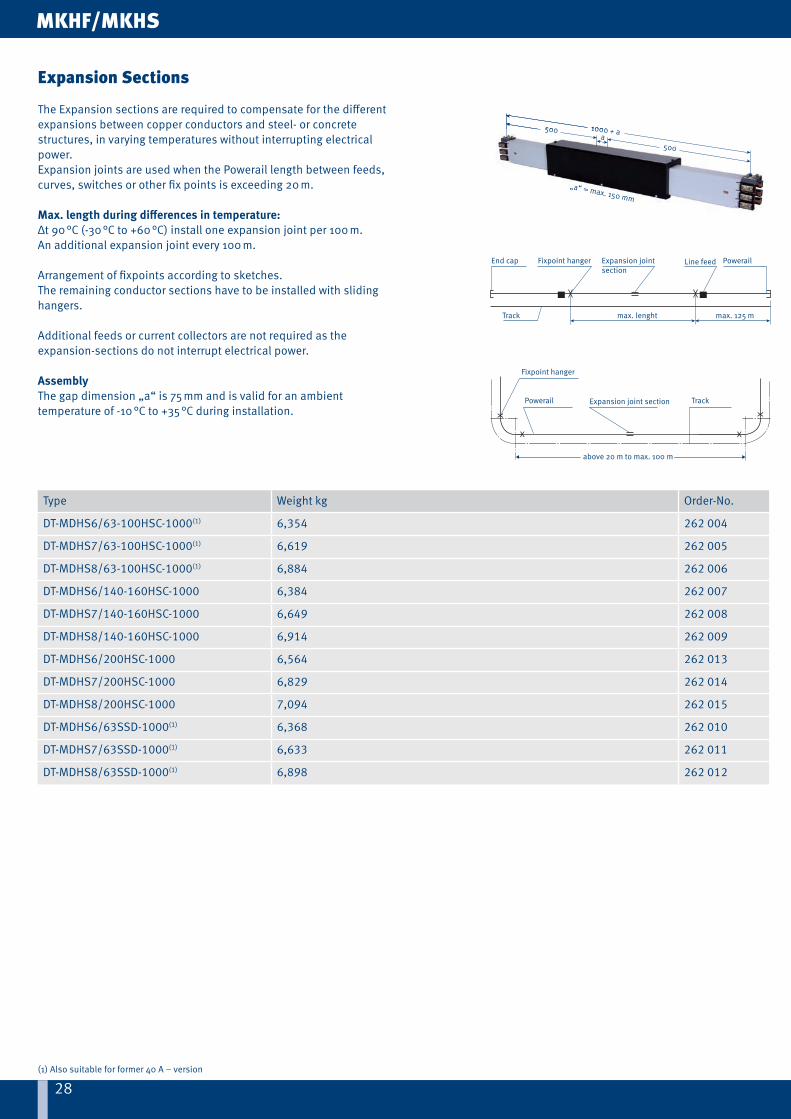
Expansion Sections
Expansion sections are required to compensate for the differentexpansions between copper conductors and steel- or concretestructures, in varying temperatures without interrupting electrical power.Expansion joints are used when the Powerail length between feeds,curves, switches or other fix points is exceeding 10 m.
Max. length during differences in temperature:Δ t 20 °C = 70 m Δ t 40 °C = 35 m Δ t 80 °C = 17 mΔ t 30 °C = 45 m Δ t 60 °C = 23 m
Longer runs or higher differences in temperature require more expansion joints.X = max. 55 m for outdoor systemsX = max. 100 m for indoor systems
MKHD
28
1000 + a500
500a
„a“ = max. 150 mm
28
1000 + a500
500a
„a“ = max. 150 mm
End cap Fixpoint hanger Expansion jointsection
max. 125 mTrack max. lenght
Line feed Powerail
X
X
X
X
Fixpoint hanger
Powerail Expansion joint section Track
above 20 m to max. 100 m
MKHF/MKHS
Type Weight kg Order-No.
DT-MDHS6/63-100HSC-1000(1) 6,354 262 004
DT-MDHS7/63-100HSC-1000(1) 6,619 262 005
DT-MDHS8/63-100HSC-1000(1) 6,884 262 006
DT-MDHS6/140-160HSC-1000 6,384 262 007
DT-MDHS7/140-160HSC-1000 6,649 262 008
DT-MDHS8/140-160HSC-1000 6,914 262 009
DT-MDHS6/200HSC-1000 6,564 262 013
DT-MDHS7/200HSC-1000 6,829 262 014
DT-MDHS8/200HSC-1000 7,094 262 015
DT-MDHS6/63SSD-1000(1) 6,368 262 010
DT-MDHS7/63SSD-1000(1) 6,633 262 011
DT-MDHS8/63SSD-1000(1) 6,898 262 012
(1) Also suitable for former 40 A – version
Expansion Sections
The Expansion sections are required to compensate for the differentexpansions between copper conductors and steel- or concretestructures, in varying temperatures without interrupting electrical power.Expansion joints are used when the Powerail length between feeds,curves, switches or other fix points is exceeding 20 m.
Max. length during differences in temperature:Δt 90 °C (-30 °C to +60 °C) install one expansion joint per 100 m.An additional expansion joint every 100 m.
Arrangement of fixpoints according to sketches.The remaining conductor sections have to be installed with slidinghangers.
Additional feeds or current collectors are not required as theexpansion-sections do not interrupt electrical power.
AssemblyThe gap dimension „a“ is 75 mm and is valid for an ambienttemperature of -10 °C to +35 °C during installation.

2929
220
151
Cable 1 Cable 2
Type Weight kg No. of con-ductors
Power ratingat 60 % DC in A
ø of connecting-cables in mm Order - No.
Cable 1 Cable 2
SA-MSWA6/50-1HS28-60 1,254 6 50 ≈ 17,0 ≈ 7,0 236 177
SA-MSWA7/50-1HS28-60 1,307 7 50 ≈ 17,0 ≈ 7,5 236 178
SA-MSWA8/50-1HS28-60 1,369 8 50 ≈ 17,0 ≈ 8,0 236 179
SA-MSWA9/50-1HS28-60 1,484 9 50 ≈ 17,0 ≈ 9,0 236 180
SA-MSWA10/50-1HS28-60 1,592 10 50 ≈ 17,0 ≈ 9,5 236 181
SA-MSWA6/25-1SS28-60 0,922 6 25 ≈ 11,5 - 236 182
SA-MSWA7/25-1SS28-60 0,958 7 25 ≈ 11,5 - 236 183
SA-MSWA8/25-1SS28-60 1,030 8 25 ≈ 10,0 ≈ 10,0 236 184
SA-MSWA9/25-1SS28-60 1,158 9 25 ≈ 11,0 ≈ 10,0 236 185
SA-MSWA10/25-1SS28-60 1,347 10 25 ≈ 11,5 ≈ 10,0 236 186
Collectors
Single collector MSWAupto max. 180 m/min.In conductor rails with sealing strip upto 100 m/min.
Connecting cables:for power line: cable 1 → 4 x 6 mm2
cable 2 → … x 1,5 mm2
for control line: cable 1 → … x 2,5 mm2
(two cables for 8-pole and more) For curves use single collectors only.Connecting cable 1 m, longer cable available
Example of ordering double collectors with 2 m cableOder - No. 236 177-2for collector SA-MSWA6/50-1HS28-60
Cleaning trolleys on request
MKHD/MKHF/MKHS

3030
335
152
Cable 1 Cable 2
30
MKHD/MKHF/MKHS
Type Weight kg No. of con-ductors
Power ratingat 60 % DC in A
ø of connecting-cables in mm Order - No.
Cable 1 Cable 2
SA-MSWAS6/50-1HS28-60 1,354 6 50 ≈ 17,0 ≈ 7,0 236 200
SA-MSWAS7/50-1HS28-60 1,407 7 50 ≈ 17,0 ≈ 7,5 236 201
SA-MSWAS8/50-1HS28-60 1,469 8 50 ≈ 17,0 ≈ 8,0 236 202
SA-MSWAS9/50-1HS28-60 1,584 9 50 ≈ 17,0 ≈ 9,0 236 203
SA-MSWAS10/50-1HS28-60 1,692 10 50 ≈ 17,0 ≈ 9,5 236 204
SA-MSWAS6/25-1SS28-60 1,022 6 25 ≈ 11,5 - 236 205
SA-MSWAS7/25-1SS28-60 1,058 7 25 ≈ 11,5 - 236 206
SA-MSWAS8/25-1SS28-60 1,130 8 25 ≈ 10,0 ≈ 10,0 236 207
SA-MSWAS9/25-1SS28-60 1,258 9 25 ≈ 11,0 ≈ 10,0 236 208
SA-MSWAS10/25-1SS28-60 1,447 10 25 ≈ 11,5 ≈ 10,0 236 209
Collectors
Single collector MSWASupto max. 250 m/min.In conductor rails with sealing strip upto 100 m/min.
Connecting cables:for power line: cable 1 → 4 x 6 mm2
cable 2 → … x 1,5 mm2
for control line: cable 1 → … x 2,5 mm2
(two cables for 8-pole and more)
For curves use single collectors only.Connecting cable 1 m, longer cable available
Example of ordering double collectors with 2 m cableOder - No. 236 000-2for collector SA-MSWAS6/50-1HS28-60
3131
530
310
Cable 1
Cable 2
153
31
MKHD/MKHF/MKHS
Type Weight kg No. of con-ductors
Power ratingat 60 % DC in A
ø of connecting-cables in mm Order - No.
Cable 1 Cable 2
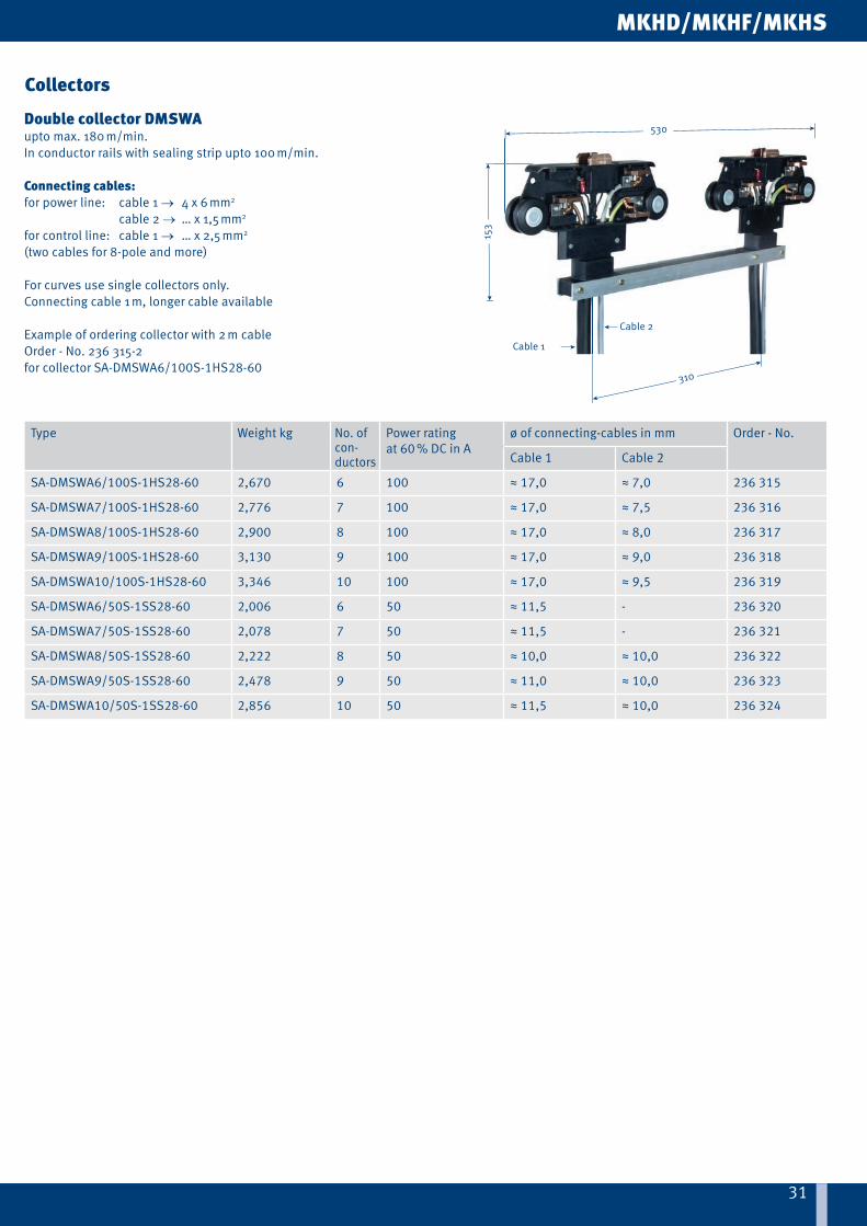
SA-DMSWA6/100S-1HS28-60 2,670 6 100 ≈ 17,0 ≈ 7,0 236 315
SA-DMSWA7/100S-1HS28-60 2,776 7 100 ≈ 17,0 ≈ 7,5 236 316
SA-DMSWA8/100S-1HS28-60 2,900 8 100 ≈ 17,0 ≈ 8,0 236 317
SA-DMSWA9/100S-1HS28-60 3,130 9 100 ≈ 17,0 ≈ 9,0 236 318
SA-DMSWA10/100S-1HS28-60 3,346 10 100 ≈ 17,0 ≈ 9,5 236 319
SA-DMSWA6/50S-1SS28-60 2,006 6 50 ≈ 11,5 - 236 320
SA-DMSWA7/50S-1SS28-60 2,078 7 50 ≈ 11,5 - 236 321
SA-DMSWA8/50S-1SS28-60 2,222 8 50 ≈ 10,0 ≈ 10,0 236 322
SA-DMSWA9/50S-1SS28-60 2,478 9 50 ≈ 11,0 ≈ 10,0 236 323
SA-DMSWA10/50S-1SS28-60 2,856 10 50 ≈ 11,5 ≈ 10,0 236 324
Collectors
Double collector DMSWAupto max. 180 m/min.In conductor rails with sealing strip upto 100 m/min.
Connecting cables:for power line: cable 1 → 4 x 6 mm2
cable 2 → … x 1,5 mm2
for control line: cable 1 → … x 2,5 mm2
(two cables for 8-pole and more)
For curves use single collectors only.Connecting cable 1 m, longer cable available
Example of ordering collector with 2 m cableOrder - No. 236 315-2for collector SA-DMSWA6/100S-1HS28-60

32
190
53100
234 bis Mitte Rohr
Kundenseitig
AA
M 8
32
190
53100
234 to center of tube
by customer
AA
M 8
190
53
100252
slotted hole9 x 30
60
51 ±
10
330 slotted hole 9 x 1890
138
90
30ca
. 152
330
slotted hole 9 x 18
ca. 8
1ca
. 64
138
treed
max. horizontal off set 15 mmmax. vertical off set 10 mm
MKHD/MKHF/MKHS
(1) For assembly use enclosed adapter plate.(2) ... / K Stainless steel.
Type Weight kg Order - No.
MN-MGU 0,632 600 334
MN-MGU/K(2) 0,550 600 336
Type Weight kg Order - No.
MN-MGF 0,524 600 335
MN-MGF/K(2) 0,442 600 337
Type Weight kg Order - No.
MN-MFMN 1,021 236 460
Tow arms
Tow armInstallation options of 30 mm square-, hollow profi le or tube with 30 - 34 mm
A - A Version with square hollow profi le(without adapter plate)
A - A version with tube(2)
Tow armfor plane surface
Flexible tow armFor single collectors – fl exible support typefor systems with transfer funnels MTH
If you are going to use the fl exible towing arm in system withcurves please contact us.
Flexible tow arm confi guration

33
MKHD/MKHF/MKHS
33
L1
(3)
MKH6 poles
L3(6)
1(2)
2(5)
L2
shaft 2
shaft 1
(1) (4)
shaft 1
MKHD/MKHF/MKHS
Type Description Weight kg/m
Type of cassette Order - No.(Cu)
Order - No.(Inox)A B C
SS-FLCU40A/11-11X1-E 11 mm2 11 x 1 mm (40 A) 0,10 90 260 300 234 198 –
SS-INOX40A/11-11x1-E 11 mm2 11 x 1 mm 0,09 90 260 300 – 234 384
Type Description Weight kg/m
Type of cassette Order - No.(Cu)
Order - No.(Inox)A B C
SS-FLCU40A/10-13X0,8-E 10 mm2 13 x 0,8 mm (63 A) 0,09 115 300 - 234 197 –
SS-FLCU80A/17-13X1,3-E 17 mm2 13 x 1,3 mm (80 A) 0,15 65 200 300 234 199 –
SS-INOX40A/17-13x1,3-E 17 mm2 13 x 1,3 mm 0,14 65 200 300 – 234 383
SS-FLCU100A/26-13X2-E 26 mm2 13 x 2 mm (100 A)(2) 0,23 45 130 200 234 200 –
SS-FLCU140A/33-13X2,5-E 33 mm2 13 x 2,5 mm (140 A)(2) 0,29 35 100 160 234 201 –
SS-FLCU160A/42-13X3,2-E 42 mm2 13 x 3,2 mm (160 A)(2) 0,37 25 80(1) 120(1) 234 202 –
Cable glands for cable-Ø in mm capacity A (execution: D/F/S) Page
M 25 and M 40 11 - 17 and 19 - 28 63 - 80 HS S. 12,13
M 25 11 - 17 63 SS S. 12,13
M 25 and M 50 9 - 19 and 23 - 34 63 - 100 HS S. 13,14
M 25 and M 50 9 - 19 and 29 - 40 163 - 200 HS S. 13,14
M 25 9 - 19 63 SS S. 13,14
M 25 für L1/L2/L3 9 - 19 63 - 200 HS S. 15, 16
M 25 für 1 - 4 and 9/10 6 - 15 63 - 200 HS S. 15, 16
M 25 6 bis 10 - poles 9 - 19 63 SS S. 15, 16
M 20 6 - 13 63 - 200 SS / HS S. 15, 16, 18
Max. length of 11 mm wide strip (for shaft 1)
(1) Values for installation through VAHLE-engineers (with help device possible). Use bolted joints and possibly expansion sections for bigger lengths than shown in the table. In this case installation by Vahle experts is recommended, especially for copper cross section of 42 mm2 and 51 mm2. Consult factory for proper layout.
(2) With straightening tool (see page 34).
Max. length of 13 mm wide strips
Flat copper (MKHD)
Flat copper and Cable Glands
Cable glands

3434
approx.5 m long
EZRD
approx.5 m long
EZR 6 - 8
approx.5 m long
EZR 9 / 10
„X“„Y“
Arrangement of the laying mechanism
Single-casette type EZK
Double-casette type DEZK
MKHD/MKHF/MKHS
Type Weight kg Dim. » X « Dim. » Y « Type of cassette Order - No.
MZ-EZK1-MKL/H 2,364 462 500 A 234 219
MZ-EZK2-MKL/H 3,890 662 700 B 234 220
MZ-EZK3-MKL/H 5,648 862 900 C 234 250
MZ-DEZK1-MKL/H 4,831 462 500 A 234 221
MZ-DEZK2-MKL/H 7,883 662 700 B 234 222
MZ-DEZK3-MKL/H 11,387 862 900 C 234 251
Type Weight kg Order - No.
MZ-RV-MKL/H 0,952 234 218
Type Weight kg Description Order - No.
MZ-EZR6-8-MKL/H 0,991 (for conductors inside housing, shafts 1 & 2) 234 204
MZ-EZR9/10-MKL/H 0,182 (for conductors outside housing, shafts 1) 234 730
DL-EZRD-MKL/H 1,197 (for sealing strip and for conductors inside housing 1 & 2) 234 552
Assembling tools
Copper cassettes
Straightening toolrequired from strip sections 26 mm2 upwards
Conductor threading tool
Type of copper cassette depends on copper cross section and system length (see page 33).

35
MKHD/MKHF/MKHS
35
MKHD/MKHF/MKHS
Quan-tity
Type MKHD MKHF MKHS
Type Order - No. Type Order - No. Type Order - No.
15 Profile section 4 m MKHD-4000HSC 262 504 - - - -
1 Profile section 3 m for short length 2.7 m
MKHD-3000HSC 262 503 - - - -
15 Conductor system 4 m - - MKHF8/100-4000HSC
262 134 MKHS8/100-4000HSC
262 344
1 Conductor system 3 m for short length 2.7 m
- - MKHF8/100-3000HSC
262 133 MKHS8/100-3000HSC
262 343
1 Line feed ES-MHGD8/63-100HSC-1000
262 547 ES-MHGF8/ 100HSC-1000
262 500 ES-MHGS6/ 100HSC-1000
262 456
1 End section, left0,3 m long
EK-MHED/L 262 537 - - - -
1 End section, right0,3 m long
EK-MHED/R 262 536 - - - -
2 End caps - - EK-MSES 235 141 EK-MSES 235 141
18 Joint caps VM-MVMD 234 678 - - - -
16 Joint caps - VM-MVMS 234 585 VM-MVMS 234 585
1 Fixpoint hanger AH-MFH 262 001 AH-MFH 262 001 AH-MFH 262 001
32 Sliding hangers AH-MGH 262 000 AH-MGH 262 000 AH-MGH 262 000
260m Flat copper strip, 4 coils à 65 m, 26mm2
SS-FLCU100A/ 26-13X2-E
234 200 - - - -
130m Flat copper strip,2 coils à 65 m, 10 mm2
SS-FLCU40A/ 10-13X0,8-E
234 197 - - - -
130m Flat copper strip,2 coils à 65 m, 11 mm2
SS-FLCU40A/ 11-11X1-E
234 198 - - - -
1 Single collector SA-MSWA8/50-1HS28-60
236 179 SA-MSWA8/50-1HS28-60
236 179 SA-MSWA8/50-1HS28-60
236 179
1 Tow arm MN-MGU 600 334 MN-MGU 600 334 MN-MGU 600 334
1 Copper cassette MZ-EZK2-MKL/H 234 220 - - - -
1 Laying mechanism MZ-RV-MKL/H 234 218 - - - -
1 Conductor threading tool MZ-EZR6-8-MKL/H
234 204 - - - -
Example for ordering
X
2700 7 x 4000 1000 8 x 4000
max. 80 m max. 80 m
XX system lenght 63,7 m
MKH ...8/100....HSC (see pages 5 & 6)X = 300 mm end section for copper conductor MKHD (w/o cond.)Not for MKHF & MKHS.

36
MKHD/MKHF/MKHS
36
MKHD/MKHF/MKHS
Type Description Order - No.
SK-KSW-MSWA-PH/SU-28 Carbon Phase (lateral, 9th and 10th pole) 600 088
SK-KSW-MSWA-PE/S-28 Carbon Ground (lateral, PE) 600 090
SK-MSWA-PH/O-28 Carbon top (7th and 8th pole) 236 187
SA-KF-KSW-MSWA-SP Carbon spring standard (for all carbons, pair) 600 338
TR-DMSW/A-SF310 Rigid bar for DMSW & DMSWA 234 515
SA-ZB-AS-MSWA-P-250 High speed set for collector MSWAS 236 199
SA-ZB-DG-MSWA-S Sealing strip slide plate for collectors MSWA 236 625
Type Description Order - No.
VM-STV11/40A-MKHF Plug-in joint for MKHF (11 mm Cu; 40 A) 262 020
VM-STV13/63-100A-KBHF/MKHF(1) Plug-in joint for MKHF (13 mm Cu; 63–100 A) 600 483
VM-SCHV11/40A-MKHS/MKLS Bolted joint for MKHS (11 mm Cu; 40 A) 262 019
VM-SCHV13/63-200A-KBHS/MKHS/MKLS(1) Bolted joint for MKHS (13 mm Cu; 63–200 A) 262 018
VM-MVMT-MT-MU/S-9/10POL Joint Cap for transfer guide and transfer funnel, pair(MKHD, MKHF und MKHS)
234 779
DL-D-KBH-MKH-MKL-TDV Sealing strip (max. length each 40 m) 600 551
DL-V-KSLT-KBH-MKL/H-LSV/G Coupling for sealing strip, in pairs (2 per joint) 258 300
DL-F-MKL/H Fixing clamp for sealing strip (1 per end) 236 105
Cleaning accessories on request
(1) Also suitable for former 40 A – version
Spare parts
for enclosed conductor system
for collector MSWA

3737
Reading head
next Position
FeaturesFeatures
APOS Positioning system
were developed for automated handling systems in material fl ow technology.The control system can constantly query the absolute position of the mobile consumer.The APOS Positioning System can be used in connection with the VAHLE Powercom® Data Transmission System.
Features
• absolute position determination up to and 262 m• Systems for exceeded lengths on request • Space-saving solutions for integration into the powerail system or for installation in parallel to the runway• retrofittable• absolute position immediately available when switching on or after a power failure• reliable position detection even in humid or dusty environments• trouble-free functionality even in poor lighting conditions• travel speed up to 250 m/min• no wear (contactless)
For more information see our catalog VAHLE APOS® (7a)

3838
VAHLE Powercom®
187,5 kbps
19,2 kbps
1
11
2
3
VAHLE Powercom® 485
• RS 485 Interface (transparent protocol)• to be used in various BUS-Systems.• Transfer rate 19.2 kbps
VAHLE Powercom® 485-HD
• SRS 485 Interface (transparent protocol)• to be used in various BUS-Systems • Transfer rate from 28,8 upto 187,5 kbps
VAHLE Powercom®-Data transmission systems in conjunction with VAHLE conductor bars or sliprings were developed for automated handling systems in material fl ow technology. They enable the uninterrupted and cost eff ective data transfer between the central control system and the accompanying automation devices on the conveying vehicles. The VAHLE Powercom® data transmission system can be used in connection with the VAHLE Powercom® Data Transmission System.
187,5 kbps
19,2 kbps
Example of use
1 VAHLE-Powercom®
2 VAHLE-Powercom® Double fi lter
3 VAHLE-Powercom® Terminal resistance
1
11
2
3
For more information see our catalog VAHLE POWERCOM® (6a)

3939
QuestionnaireCompany: ___________________________________________________ Date: ______________________________________________________
Fon: ________________________________________________________ Fax: ________________________________________________________
email: ______________________________________________________ Internet: ____________________________________________________
1. Number of conductor system installations: __________________________________________________________________________________
2. Type of equipment to be powered: _________________________________________________________________________________________
3. Operatin voltage: _________Volt Frequency: _____ Hz
Three phase voltage: AC voltage: DC voltage:
4. Track lenght: ____________________________________________________________________________________________________________
5. Number of conductors: ____________ neutral: __________ control: ______________ ground: ____________
6. Mounted position of conductor system:
Conductor pendant / collector cable facing to the bottom Conductor pendant / collector cable lateral payout(1)
Support distance m (max. 2 m) Other: ____________________________________________________
7. Number of consumers per system:
8. Indoor: Outdoor:
9. Special operating conditions (humidity, dust, chemical influences etc.) _________________________________________________________
10. Ambient temperature: _______________°C min. _____________ °C max.
11. Hall expansion joints: _______________ pieces. min. __________ max. __________ expansion.
12. Position and number of feeding points(1): ____________________________________________________________________________________
13. Position and number of isolating sections (e.g. for maintenance)(1): _____________________________________________________________
14. How will the conductor system be arranged?(1): _______________________________________________________________________________
15. Brackets required: yes ; no c/c distance beam / conductor system __________________________
Flange width of beam: ________________________________________
16. Travel speed: _____________________________________ in curves: ___________ at transfers: ________________________
17. Max. voltage drop from the conductor feed point to the cosumer considering starting current:
3% oder ________% referring to the nominal voltage.
18. Power consumption of the individual consumer loads: ________________________________________________________________________
Mark with * those motors which can run simutnaneously
Mark with Δ those motors which can start up simultaneously
Further remarks: ______________________________________________________________________________________________________________
_____________________________________________________________________________________________________________________________
_____________________________________________________________________________________________________________________________
_____________________________________________________________________________________________________________________________
Signature _________________________________
Motor data
Crane 1 Crane 2
Power kW
Nominal current Starting current Type ofMotors
(2)
Power kW
Nominal current Starting current Type ofMotors
(2)A cos ФN % DC A cos ФA A cos ФN % DC A cos ФA
Hoist motors
Auxiliary hoist
Long travel
Cross travel
(1) Sketches required for quotation(2) Use: K for squirrel cage motor, S for slipring motor, F for frequency controlled motorWe reserve all rights to make alterations in the interest of further development.Please copy and fill in the questionaire.

W10
1754
6/en
-700
-01/
16 |
Erro
rs a
nd te
chni
cal m
odifi
catio
ns s
ubje
ct to
cha
nge
1 Open conductor systemsOpen conductor systems 1a
2 Insulated conductor systemsU10 2a
FABA 100 2b
U15, U25, U35 2c
U20, U30, U40 2d
3 Compact conductor systemsVKS 10 3a
VKS - VKL 3b
VMT 3c
4 Enclosed conductor systemsKBSL - KSL 4a
KBH 4b
MKH 4c
LSV - LSVG 4d
5 Contactless power supplyContactless power supply (CPS®) 5a
6 Data transmissionVAHLE Powercom® 6a
Slotted Microwave Guide (SMG) 6b
7 Positioning systemsVAHLE APOS® 7a
VAHLE APOS® Optic 7b
8 Festoon systems and cablesFestoon systems for -tracks 8a
Festoon systems for fl atform cables on -tracks 8b
Festoon systems for round cables on -tracks 8c
Festoon systems for -tracks 8d
Cables 8e
9 ReelsSpring-operated cable reels 9a
Motor-powered cable reels 9b
10 OtherBattery charging systems 10a
Heavy enclosed conductor systems 10b
Tender 10c
Contact wire 10d
11 Automotive | HandlingControl systems 11a
BOK 11b
Assemblies / CommissioningSpare parts / Maintenance service
Scope of delivery and services Catalog no.
DQS certifi ed in accordance with DIN EN ISO 9001:2008OHSAS 18001 (Reg.No. 003140 QM OH)
Kamen/Germany +49 2307 704-0 · [email protected] · www.vahle.com