switchgear and controlgear assembly documentation · switchgear and controlgear assembly...
TRANSCRIPT
Switchgear and controlgear assembly documentationassembly documentationRequirements of the documentation in accordance with:IEC 60204-1 – Electrical equipment of machinesIEC 60204-1 Electrical equipment of machines
IEC 61439-1 – Low-voltage switchgear and controlgear assemblies
© Siemens Industry Inc. 2013. All rights reserved.

Switchgear and controlgear assembly documentation
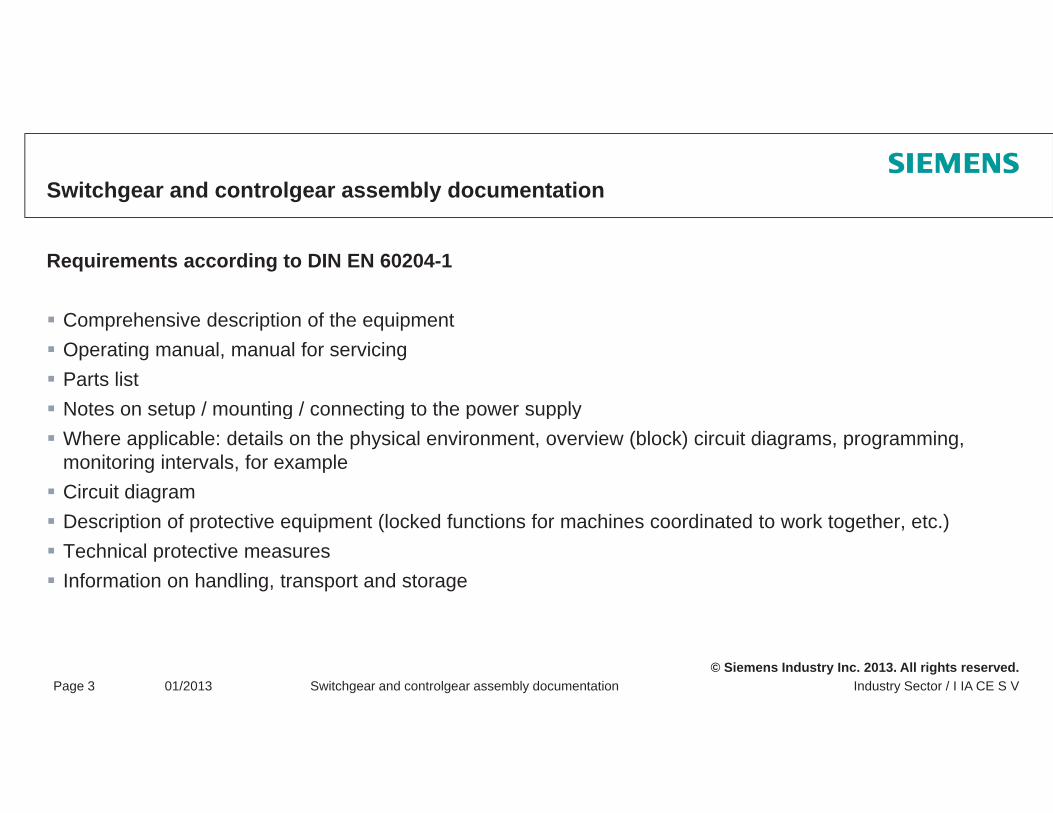
Requirements according to DIN EN 60204-1
The information that is required for setting up, operating, and servicing a machine's electrical equipment must be supplied in a suitable format.The information must be in an agreed language.The form of information provided may vary depending on the complexity of the electrical equipment deliveredThe form of information provided may vary depending on the complexity of the electrical equipment delivered.For very simple equipment, the corresponding information may be contained within a single document, provided that this document shows all the devices of the electrical equipment and enables connections to be established to the power supply.
REMARK: The technical documentation that is provided with parts of the electrical equipment can form part of the documentation for the machine's electrical equipment.
© Siemens Industry Inc. 2013. All rights reserved.Industry Sector / I IA CE S VPage 2 01/2013 Switchgear and controlgear assembly documentation
Switchgear and controlgear assembly documentation
Requirements according to DIN EN 60204-1
Comprehensive description of the equipmentOperating manual, manual for servicingParts listNotes on setup / mounting / connecting to the power supplyNotes on setup / mounting / connecting to the power supplyWhere applicable: details on the physical environment, overview (block) circuit diagrams, programming, monitoring intervals, for exampleCircuit diagramDescription of protective equipment (locked functions for machines coordinated to work together, etc.)Technical protective measuresInformation on handling, transport and storage
© Siemens Industry Inc. 2013. All rights reserved.Industry Sector / I IA CE S VPage 3 01/2013 Switchgear and controlgear assembly documentation

Switchgear and controlgear assembly documentation
Requirements according to DIN EN 61439-1
All identifying characteristics of the switchgear and controlgear assembly must be contained within the technical documentationNotes on transport, handling, installation, operation, and servicingIdentification of devices, components, electrical circuits (parts lists, assembly drawings, circuit diagrams, and terminal diagrams)
Note: No separate requirements for power switchgear and controlgear assemblies (DIN EN 61439 2)Note: No separate requirements for power switchgear and controlgear assemblies (DIN EN 61439-2)
© Siemens Industry Inc. 2013. All rights reserved.Industry Sector / I IA CE S VPage 4 01/2013 Switchgear and controlgear assembly documentation
Switchgear and controlgear assembly documentation
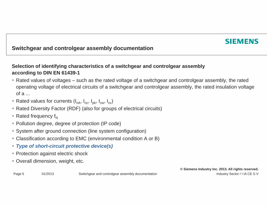
Selection of identifying characteristics of a switchgear and controlgear assembly according to DIN EN 61439-1
Rated values of voltages – such as the rated voltage of a switchgear and controlgear assembly, the rated operating voltage of electrical circuits of a switchgear and controlgear assembly, the rated insulation voltage of a ...Rated values for currents (InA, Inc, Ipk, Icw, Icc)( nA, nc, pk, cw, cc)Rated Diversity Factor (RDF) (also for groups of electrical circuits)Rated frequency fNPollution degree, degree of protection (IP code)System after ground connection (line system configuration)Classification according to EMC (environmental condition A or B)Type of short-circuit protective device(s)Protection against electric shock
© Siemens Industry Inc. 2013. All rights reserved.Industry Sector / I IA CE S VPage 5 01/2013 Switchgear and controlgear assembly documentation
Protection against electric shockOverall dimension, weight, etc.

(1) A brief excursion covering the type of short-circuit protective device(s) according to DIN EN 61439-1
For switchgear and controlgear assemblies with a short-circuit protective device in the infeed, the user should specify the value of the prospective short circuit current which can arise at the inputthe prospective short-circuit current which can arise at the inputconnections of the switchgear and controlgear assembly.
Result:The manufacturer must provide a marking or documentation whichspecifies the short-circuit withstand strength of the switchgear and controlgear assembly for which the short-circuit protective device on the infeed provides protectionon the infeed provides protection.
© Siemens Industry Inc. 2013. All rights reserved.Industry Sector / I IA CE S VPage 6 01/2013 Switchgear and controlgear assembly documentation
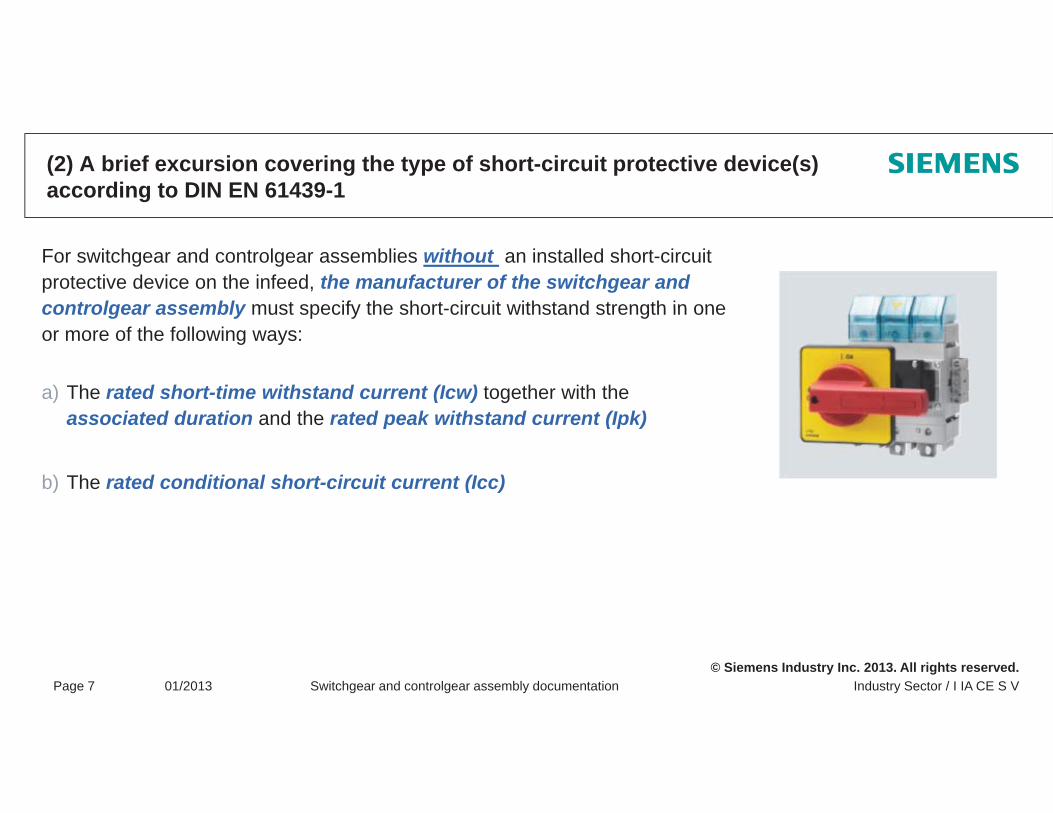
(2) A brief excursion covering the type of short-circuit protective device(s) according to DIN EN 61439-1
For switchgear and controlgear assemblies without an installed short-circuit protective device on the infeed, the manufacturer of the switchgear and controlgear assembly must specify the short circuit withstand strength in onecontrolgear assembly must specify the short-circuit withstand strength in oneor more of the following ways:
a) The rated short-time withstand current (Icw) together with the associated duration and the rated peak withstand current (Ipk)
b) The rated conditional short-circuit current (Icc)
© Siemens Industry Inc. 2013. All rights reserved.Industry Sector / I IA CE S VPage 7 01/2013 Switchgear and controlgear assembly documentation
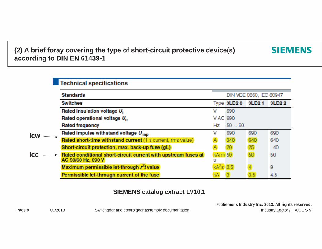
(2) A brief foray covering the type of short-circuit protective device(s) according to DIN EN 61439-1
Icw
IccIcc
© Siemens Industry Inc. 2013. All rights reserved.Industry Sector / I IA CE S VPage 8 01/2013 Switchgear and controlgear assembly documentation
SIEMENS catalog extract LV10.1

Thank you for your attention!Any questions?
Note / exclusion of liability
The typical circuit diagrams and interpretations of the standard are not binding and do not claim to be complete regarding configuration, equipment or any other eventuality. They do not represent any client-specific solutions and are only intended to offer assistance for typical tasksspecific solutions and are only intended to offer assistance for typical tasks.
Each person viewing this presentation is responsible for the correct operation of the products described. This presentation does not relieve you of your responsibility regarding safe handling when using, installing, operating, and maintaining the equipment.
By viewing this presentation you agree that Siemens cannot be made liable for possible damage beyond theBy viewing this presentation you agree that Siemens cannot be made liable for possible damage beyond theabove mentioned liability clause.We reserve the right to make changes and revisions to this informational documentation without prior announcement.
When writing these guidelines, a lot of tables and texts were lifted straight from the relevant standards. All g g gusers of this documentation must always check whether the items quoted are still up to date or not. The final decision about the appropriateness of applying the applicable standards must be made by the user of this documentation.
The reproduction of this presentation and its distribution, utilization or the dissemination of its contents to
© Siemens Industry Inc. 2013. All rights reserved.
The reproduction of this presentation and its distribution, utilization or the dissemination of its contents tothird parties is not permitted.
Documentation in line with LVD
Documentation requirements in line with the Low Voltage Directive 2006/95/ECDirective 2006/95/EC
© Siemens Industry Inc. 2013. All rights reserved.
Documentation in line with the low-voltage directive
Process for the CE – Declaration of Conformity and marking in line with LVD 2006/95/ECLVD 2006/95/EC1. Method2. Declaration of Conformity 3 CE marking3. CE markingExample for the Declaration of Conformity and the CE marking
© Siemens Industry Inc. 2013. All rights reserved.
Path to CE marking
© Siemens Industry Inc. 2013. All rights reserved.Industry Sector / I IA CE S VPage 3 01/2013 Documentation in line with LVD

Conformity assessment procedure
Conformity must be assessed by the manufacturer or someone authorized by them and based within the Community. The conformity assessment procedure incorporates 3 main steps.
1. Compiling the technical documentation
2. Declaration of Conformity
Th bli ti ( th d ) d t l t th i t h ill ll h d t il d k l d
3. CE marking
© Siemens Industry Inc. 2013. All rights reserved.Industry Sector / I IA CE S VPage 4 01/2013 Documentation in line with LVD
These obligations (methods) do not apply to the importer, who will generally have no detailed knowledgeregarding which directives have been taken into account or which technical specifications have been applied.
1. Compiling the technical documentationScope (corresponding to Annex IV of the LVD – internal production monitoring)
The technical documentation incorporates the following:
General description of the electrical switching devices and componentsp g p
Design and production plans and circuit diagrams showing how components, modules, and circuits, etc. are arranged
Descriptions and explanations to help people understand these plans and circuit diagrams and operate theDescriptions and explanations to help people understand these plans and circuit diagrams and operate theelectrical switching devices and components (Objective: third-parties must be able to understand)
A list of standards applied (in full or in part) or, if no standards have been applied, a description of the means by which the safety requirements of the directive have been satisfied
B f d t i b ht i t i l ti th f t d t il th i t h i l d t ti
The results of the design calculations, tests performed, etc.
Test reports (available test reports from the manufacturer or third parties)
© Siemens Industry Inc. 2013. All rights reserved.Industry Sector / I IA CE S VPage 5 01/2013 Documentation in line with LVD
Before a product is brought into circulation the manufacturer needs to compile the various technical documentationverification that the products satisfies the directive.
1. Compiling the technical documentationRetention
Retention of technical documentation:
For at least 10 years by the manufacturer or authorized partyy y p y
Readily accessible (e.g. in electronic form too)
Importer or party bringing product into circulation is responsible for documentation retention if the manufacturer or their authorized party is not based within the Community.manufacturer or their authorized party is not based within the Community.
Must be made available within a reasonable period of time if requested by the authorities (e.g. within 2 weeks)
© Siemens Industry Inc. 2013. All rights reserved.Industry Sector / I IA CE S VPage 6 01/2013 Documentation in line with LVD
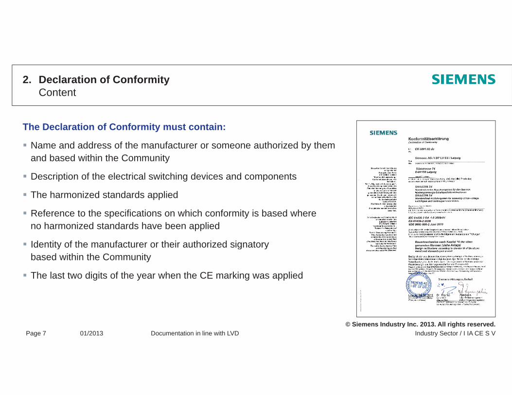
2. Declaration of ConformityContent
The Declaration of Conformity must contain:
Name and address of the manufacturer or someone authorized by them yand based within the Community
Description of the electrical switching devices and components
The harmonized standards appliedThe harmonized standards applied
Reference to the specifications on which conformity is based whereno harmonized standards have been applied
Identity of the manufacturer or their authorized signatoryIdentity of the manufacturer or their authorized signatorybased within the Community
The last two digits of the year when the CE marking was applied
© Siemens Industry Inc. 2013. All rights reserved.Industry Sector / I IA CE S VPage 7 01/2013 Documentation in line with LVD
2. Declaration of ConformityRetention
The Declaration of Conformity must be made available and retained by theManufacturer or
B d ith th C it (EEA)someone authorized by them
If neither are based within the Community, a copy needs to be retained by
Based with the Community (EEA)
The importer orFor the party responsible for bringing the product into circulation
Th th iti ibl f i i th k t t f th D l ti f C f it t
The Declaration of Conformity must be drafted in at least one of the official European languages.
The authorities responsible for supervising the market can request a copy of the Declaration of Conformity atany time if necessary.
© Siemens Industry Inc. 2013. All rights reserved.Industry Sector / I IA CE S VPage 8 01/2013 Documentation in line with LVD
The Declaration of Conformity must be drafted in at least one of the official European languages.
Official languages within the EU: 23 Working languages: 3 (English, French, German)
3. CE marking
Marking of electrical switching devices and components with CE marking before it is brought into circulation by the manufacturer only or someone authorized by them and based within the Community
CE marking applied to the electrical switching devices and components themselves or, if this is not possible, to the packaging, the user instructions, or the warranty certificate
Marking must be clearly visible, legible, and permanent.
Minimum height 5mm with proportions retained if enlarged
© Siemens Industry Inc. 2013. All rights reserved.Industry Sector / I IA CE S VPage 9 01/2013 Documentation in line with LVD
3. CE marking
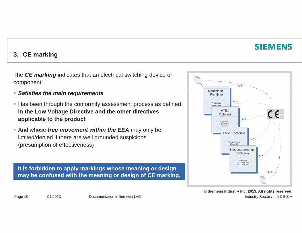
The CE marking indicates that an electrical switching device or component:
Ja ?
Satisfies the main requirements
Has been through the conformity assessment process as defined in the Low Voltage Directive and the other directives
Maschinen -Richtlinie
Produkt istMaschine
ATEXRichtlinie
Ja ?
applicable to the product
And whose free movement within the EEA may only be limited/denied if there are well grounded suspicions (presumption of effectiveness)
Explosions-gefährdeteBereiche
Ja ?
Ja ?
EMV - Richtlinie
KennzeichnungErforderlich(presumption of effectiveness)
It is forbidden to apply markings whose meaning or design b f d ith th i d i f CE ki
Ja ?
Niederspannungs-Richtlinie
Spannung50 … 1000 Vac75 … 1500 Vdc
Ja ?
© Siemens Industry Inc. 2013. All rights reserved.Industry Sector / I IA CE S VPage 10 01/2013 Documentation in line with LVD
may be confused with the meaning or design of CE marking.
Examples of the declaration of conformity, rating plate, and the CE marking
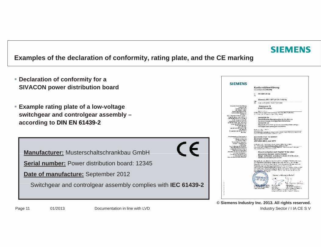
Declaration of conformity for a SIVACON power distribution board
Example rating plate of a low-voltage switchgear and controlgear assembly –according to DIN EN 61439DIN EN 61439--22according to DIN EN 61439DIN EN 61439 22
Manufacturer: Musterschaltschrankbau GmbHManufacturer: Musterschaltschrankbau GmbH
Serial number: Power distribution board: 12345
Date of manufacture: September 2012
S it h d t l bl li ith IEC 61439 2
© Siemens Industry Inc. 2013. All rights reserved.Industry Sector / I IA CE S VPage 11 01/2013 Documentation in line with LVD
Switchgear and controlgear assembly complies with IEC 61439-2
Thank you for your attention!Any questions?
Note / Exclusion of liability
The typical circuit diagrams and interpretations of the standard are not binding and do not claim to be complete regarding configuration, equipment or any other eventuality. They do not represent any client-specific solutions and are only intended to offer assistance for typical tasksspecific solutions and are only intended to offer assistance for typical tasks.
Each person viewing this presentation is responsible for the correct operation of the products described. This presentation does not relieve you of your responsibility regarding safe handling when using, installing, operating, and maintaining the equipment.
By viewing this presentation you agree that Siemens cannot be made liable for possible damage beyond theBy viewing this presentation you agree that Siemens cannot be made liable for possible damage beyond theabove mentioned liability clause.We reserve the right to make changes and revisions to this informational documentation without prior announcement.
When writing these guidelines, a lot of tables and texts were lifted straight from the relevant standards. All g g gusers of this documentation must always check whether the items quoted are still up to date or not. The final decision about the appropriateness of applying the applicable standards must be made by the user of this documentation.
The reproduction of this presentation and its distribution, utilization or the dissemination of its contents to
© Siemens Industry Inc. 2013. All rights reserved.
The reproduction of this presentation and its distribution, utilization or the dissemination of its contents tothird parties is not permitted.
Switchgear and controlgear assembly markingassembly marking
Requirements according to IEC 60204-1Requirements according to IEC 61439-1
-
© Siemens Industry Inc. 2013. All rights reserved.
Switchgear and controlgear assembly marking
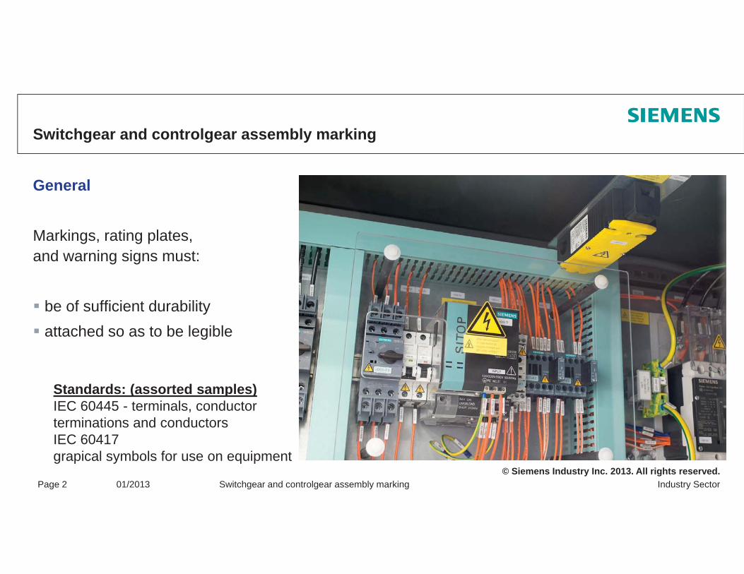
General
Markings, rating plates, and warning signs must:
be of sufficient durabilityattached so as to be legible
Standards: (assorted samples)IEC 60445 - terminals, conductor terminations and conductors
© Siemens Industry Inc. 2013. All rights reserved.Industry SectorPage 2 01/2013 Switchgear and controlgear assembly marking
terminations and conductorsIEC 60417 grapical symbols for use on equipment

Switchgear and controlgear assembly marking
Additional requirements according to IEC 60204-1 (16.4)A rating plate is to be put on the control panel which should be easily recognizable following installation. The rating plate must be attached to the enclosure around the infeed.
Name or company sign of the manufacturer / supplierIf necessary, approval symbolsSerial number / type designationRated voltage, number of phases, frequency (with alternating voltage), full load current for the infeed(s)infeed(s)Short-circuit coordination of the equipmentNumber of the main documentation
© Siemens Industry Inc. 2013. All rights reserved.Industry SectorPage 3 01/2013 Switchgear and controlgear assembly marking
Note: Full load current under normal operating conditions (be aware of the rated diversity factor (RDF)

Switchgear and controlgear assembly marking
Requirements according to IEC 61439-1The manufacturer of the control panel must place one or several permanent inscriptions on each control panel so that these are legible when the control panel is connected and in operation:
Name or trademark of the manufacturer of the control panel Type designation / identification number, with which necessary information can be requested from the manufacturer of the control panelMarking for determining the date of manufactureIEC 61439 X (the applicable part is to be specified)IEC 61439-X (the applicable part is to be specified)
Note:The applicable control panel standard may determine whether further details must be specified on the
© Siemens Industry Inc. 2013. All rights reserved.Industry SectorPage 4 01/2013 Switchgear and controlgear assembly marking
The applicable control panel standard may determine whether further details must be specified on theidentification plate
Switchgear and controlgear assembly marking
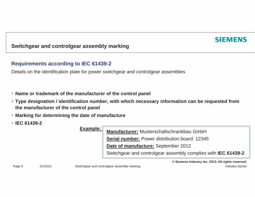
Requirements according to IEC 61439-2Details on the identification plate for power switchgear and controlgear assemblies
Name or trademark of the manufacturer of the control panelType designation / identification number, with which necessary information can be requested from the manufacturer of the control panelMarking for determining the date of manufactureIEC 61439 2IEC 61439-2
Manufacturer: Musterschaltschrankbau GmbHSerial number: Power distribution board: 12345Date of manufacture: September 2012
Example:
© Siemens Industry Inc. 2013. All rights reserved.Industry SectorPage 5 01/2013 Switchgear and controlgear assembly marking
Date of manufacture: September 2012Switchgear and controlgear assembly complies with IEC 61439-2
Thank you for your attention!Any questions?
Note / exclusion of liability
The typical circuit diagrams and interpretations of the standard are not binding and do not claim to be complete regarding configuration, equipment or any other eventuality. They do not represent any client-specific solutions and are only intended to offer assistance for typical tasksspecific solutions and are only intended to offer assistance for typical tasks.
Each person viewing this presentation is responsible for the correct operation of the products described. This presentation does not relieve you of your responsibility regarding safe handling when using, installing, operating, and maintaining the equipment.
By viewing this presentation you agree that Siemens cannot be made liable for possible damage beyond theBy viewing this presentation you agree that Siemens cannot be made liable for possible damage beyond theabove mentioned liability clause.We reserve the right to make changes and revisions to this informational documentation without prior announcement.
When writing these guidelines, a lot of tables and texts were lifted straight from the relevant standards. All g g gusers of this documentation must always check whether the items quoted are still up to date or not. The final decision about the appropriateness of applying the applicable standards must be made by the user of this documentation.
The reproduction of this presentation and its distribution, utilization or the dissemination of its contents to
© Siemens Industry Inc. 2013. All rights reserved.
The reproduction of this presentation and its distribution, utilization or the dissemination of its contents tothird parties is not permitted.

Tools for assisting with documentationdocumentation
SIMARIS software tools"My Documentation Manager"y gCAX online generator
© Siemens Industry Inc. 2013. All rights reserved.
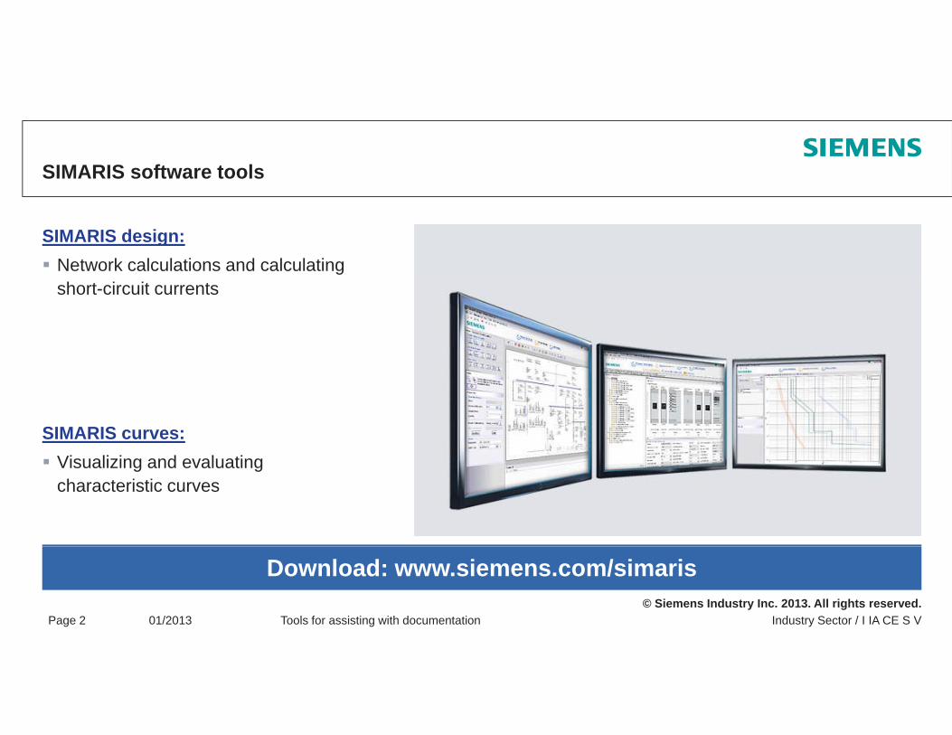
SIMARIS software tools
SIMARIS design:Network calculations and calculating short-circuit currents
SIMARIS curves:Vi li i d l tiVisualizing and evaluatingcharacteristic curves
© Siemens Industry Inc. 2013. All rights reserved.Industry Sector / I IA CE S VPage 2 01/2013 Tools for assisting with documentation
Download: www.siemens.com/simaris
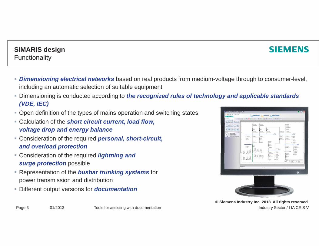
SIMARIS designFunctionality
Dimensioning electrical networks based on real products from medium-voltage through to consumer-level, including an automatic selection of suitable equipmentDimensioning is conducted according to the recognized rules of technology and applicable standards(VDE, IEC)Open definition of the types of mains operation and switching statesCalculation of the short circuit current, load flow,Calculation of the short circuit current, load flow,voltage drop and energy balanceConsideration of the required personal, short-circuit, and overload protectionConsideration of the required lightning and surge protection possibleRepresentation of the busbar trunking systems forpower transmission and distribution
© Siemens Industry Inc. 2013. All rights reserved.Industry Sector / I IA CE S VPage 3 01/2013 Tools for assisting with documentation
pDifferent output versions for documentation
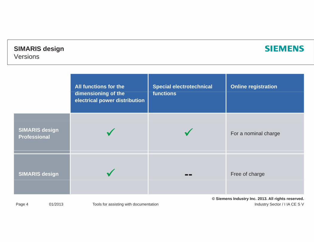
SIMARIS designVersions
All functions for the di i i f th
Special electrotechnical f ti
Online registrationdimensioning of theelectrical power distribution
functions
SIMARIS design Professional For a nominal charge
SIMARIS design -- Free of charge
© Siemens Industry Inc. 2013. All rights reserved.Industry Sector / I IA CE S VPage 4 01/2013 Tools for assisting with documentation

SIMARIS curvesFunctions
Visualization and evaluation of the tripping characteristics of low-voltage protective devices and fuses (IEC), including an option for the simulation of device settingsVisualization of cut-off current and cut-off energy characteristicsProduct selection overview per order number or selection guideSaving of selected devices as favoritesSaving of several characteristic curves including settings as a complete projectConsideration of country-specific product portfoliosUser friendly documentationUser-friendly documentation
© Siemens Industry Inc. 2013. All rights reserved.Industry Sector / I IA CE S VPage 5 01/2013 Tools for assisting with documentation
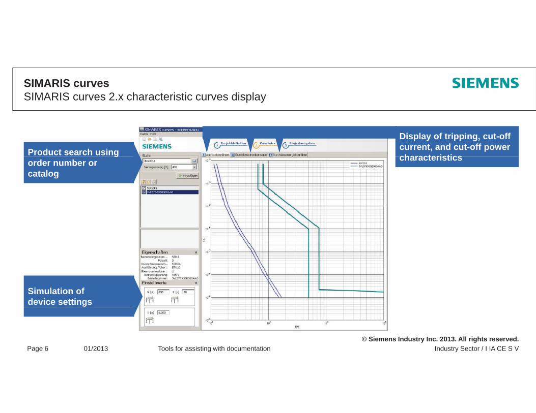
SIMARIS curvesSIMARIS curves 2.x characteristic curves display
Product search using
Display of tripping, cut-off current, and cut-off power characteristicsg
order number or catalog
characteristics
Simulation of device settings
© Siemens Industry Inc. 2013. All rights reserved.Industry Sector / I IA CE S VPage 6 01/2013 Tools for assisting with documentation
CAx online generator – Your information archive
Initial situation:A single part number or a list of Siemens order numbers (MLFBs) for an application or project.
Challenge:Individual information requirements – product information of a technical or commercial nature; e.g.
Product photoProduct photoData sheet (multilingual)Certificates / approvals / declarations of conformityCharacteristic curves
S l ti U CA li t h ill i kl d il fi d ll il bl
Engineering data for CAD or CAE systemsetc ...
© Siemens Industry Inc. 2013. All rights reserved.Industry Sector / I IA CE S VPage 7 01/2013 Tools for assisting with documentation
Solution: Use our CAx online generator – here you will quickly and easily find all availableinformation in a selection process

CAx online generator – Your information archiveCAx data types – Types of information
Product graphic3D model
Operating travel diagram
Product data sheet Operating instructions Commercial data
Operating travel diagram(only relevant for position
switches)
Technical data
2D dimension drawing
Terminal connection diagram
EPLANmacros
Manual
C
Internal circuit diagramCharacteristic Certificates/
approvals
© Siemens Industry Inc. 2013. All rights reserved.Industry Sector / I IA CE S VPage 8 01/2013 Tools for assisting with documentation
Product: CAx data curves approvals
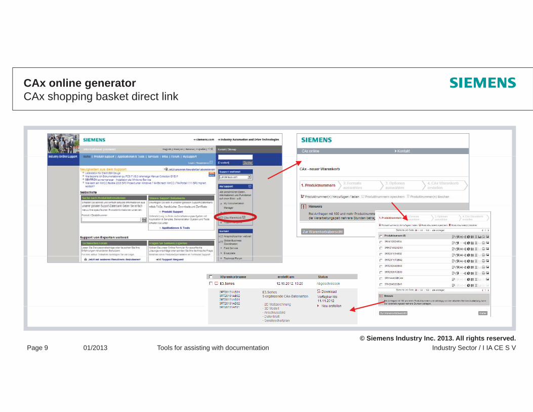
CAx online generatorCAx shopping basket direct link
© Siemens Industry Inc. 2013. All rights reserved.Industry Sector / I IA CE S VPage 9 01/2013 Tools for assisting with documentation
MDMMy Documentation Manager – Function
Compile product documentation effectively and appropriately in a separate structure and manage it comfortably
1. Select a contribution – e.g. select a manual (configurable) using the search
2. Call a contribution in MDM – e.g. select a particular chapter of a manual
3. Create / expand a separate library – add, compile, rename or delete separate folders / subject areas
4. Transfer a contribution to a separate composition – integrate contents into a separate structure using "drag and drop"g g p
5. Export function – export a separate library wholly or partially as a file (.pdf, .xml, .rtf, etc.)
© Siemens Industry Inc. 2013. All rights reserved.Industry Sector / I IA CE S VPage 10 01/2013 Tools for assisting with documentation
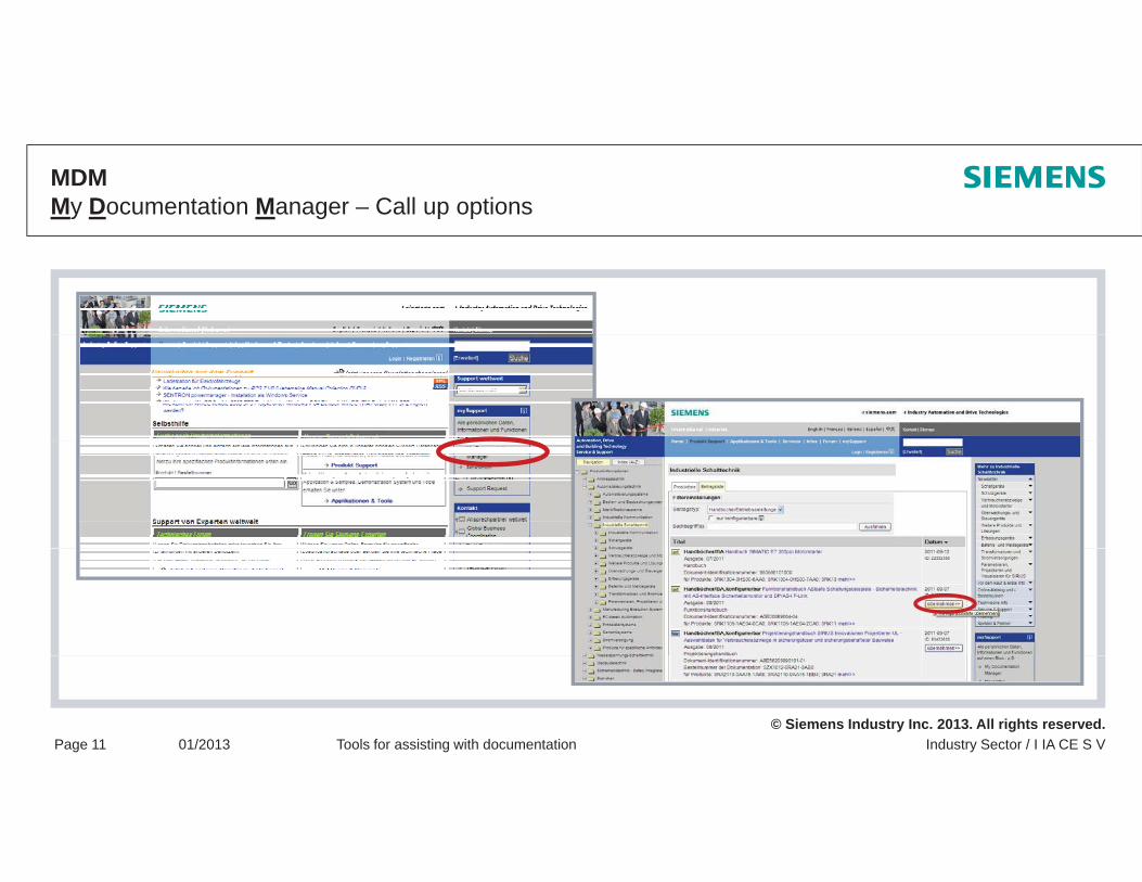
MDMMy Documentation Manager – Call up options
© Siemens Industry Inc. 2013. All rights reserved.Industry Sector / I IA CE S VPage 11 01/2013 Tools for assisting with documentation
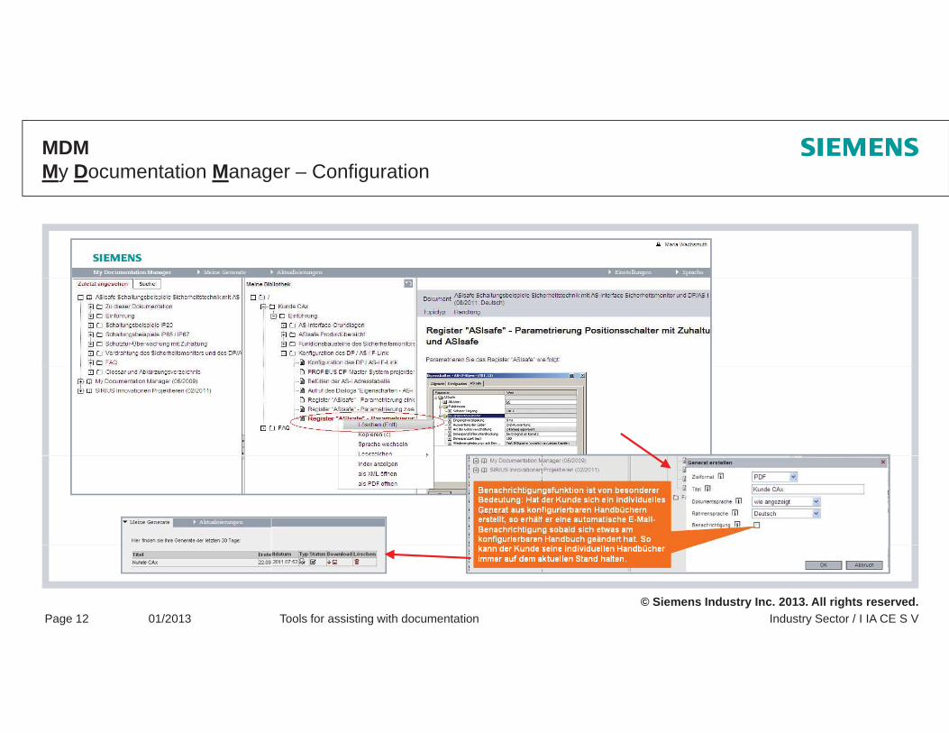
MDMMy Documentation Manager – Configuration
© Siemens Industry Inc. 2013. All rights reserved.Industry Sector / I IA CE S VPage 12 01/2013 Tools for assisting with documentation
Thank you for your attention!Any questions?
Note / exclusion of liability
The typical circuit diagrams and interpretations of the standard are not binding and do not claim to be complete regarding configuration, equipment or any other eventuality. They do not represent any client-specific solutions and are only intended to offer assistance for typical tasksspecific solutions and are only intended to offer assistance for typical tasks.
Each person viewing this presentation is responsible for the correct operation of the products described. This presentation does not relieve you of your responsibility regarding safe handling when using, installing, operating, and maintaining the equipment.
By viewing this presentation you agree that Siemens cannot be made liable for possible damage beyondBy viewing this presentation you agree that Siemens cannot be made liable for possible damage beyondthe above mentioned liability clause.We reserve the right to make changes and revisions to this informational documentation without prior announcement.
When writing these guidelines, a lot of tables and texts were lifted straight from the relevant standards. All g g gusers of this documentation must always check whether the items quoted are still up to date or not. The final decision about the appropriateness of applying the applicable standards must be made by the user of this documentation.
The reproduction of this presentation and its distribution, utilization or the dissemination of its contents to
© Siemens Industry Inc. 2013. All rights reserved.
The reproduction of this presentation and its distribution, utilization or the dissemination of its contents tothird parties is not permitted.
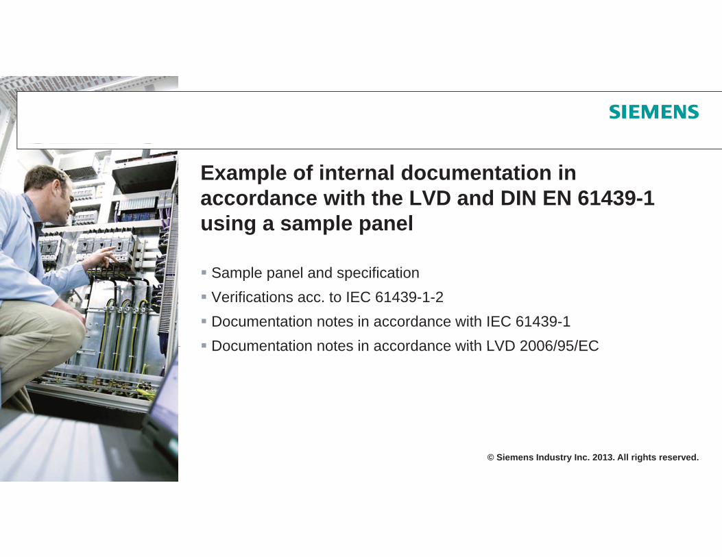
Example of internal documentation in accordance with the LVD and DIN EN 61439-1 using a sample panel
Sample panel and specificationp p pVerifications acc. to IEC 61439-1-2Documentation notes in accordance with IEC 61439-1Documentation notes in accordance with LVD 2006/95/ECDocumentation notes in accordance with LVD 2006/95/EC
© Siemens Industry Inc. 2013. All rights reserved.
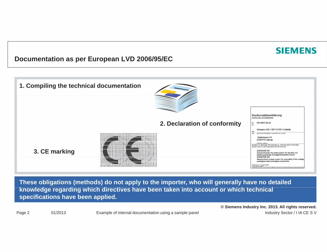
Documentation as per European LVD 2006/95/EC
1. Compiling the technical documentation
2. Declaration of conformityy
3. CE marking
These obligations (methods) do not apply to the importer, who will generally have no detailed k l d di hi h di ti h b t k i t t hi h t h i l
© Siemens Industry Inc. 2013. All rights reserved.Industry Sector / I IA CE S VPage 2 01/2013 Example of internal documentation using a sample panel
knowledge regarding which directives have been taken into account or which technicalspecifications have been applied.
Documentation as per the standard
A test report must be created for the conducting of verifications as per DIN EN 61439-1.
Chapter 10.1
"The reference design, the number of switchgear and controlgear assemblies used for the g , g gverifications, or parts of these, the choice of verification methods, providing they are applicable, and the sequence of verifications are the responsibility of the original manufacturer.
The data used, the calculations, and the comparisons conducted when verifying the switchgear and controlgear assemblies are to be documented in a test report."
© Siemens Industry Inc. 2013. All rights reserved.Industry Sector / I IA CE S VPage 3 01/2013 Example of internal documentation using a sample panel
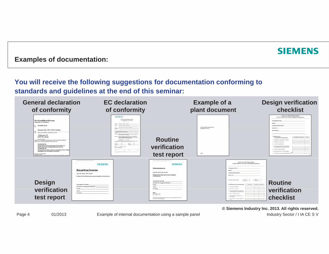
Examples of documentation:
You will receive the following suggestions for documentation conforming to standards and guidelines at the end of this seminar:
General declarationof conformity
EC declarationof conformity
Example of a plant document
Design verification checklist
Routineverificationtest report
Designverification
Routineifi ti
© Siemens Industry Inc. 2013. All rights reserved.Industry Sector / I IA CE S VPage 4 01/2013 Example of internal documentation using a sample panel
verificationtest report
verificationchecklist
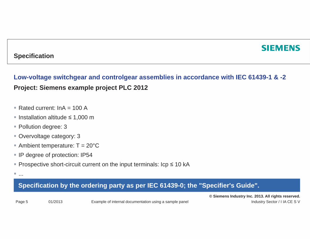
Specification
Low-voltage switchgear and controlgear assemblies in accordance with IEC 61439-1 & -2Project: Siemens example project PLC 2012j p p j
Rated current: InA = 100 AInstallation altitude 1,000 m ,Pollution degree: 3Overvoltage category: 3Ambient temperature: T = 20°CpIP degree of protection: IP54Prospective short-circuit current on the input terminals: Icp 10 kA...
© Siemens Industry Inc. 2013. All rights reserved.Industry Sector / I IA CE S VPage 5 01/2013 Example of internal documentation using a sample panel
Specification by the ordering party as per IEC 61439-0; the "Specifier's Guide".
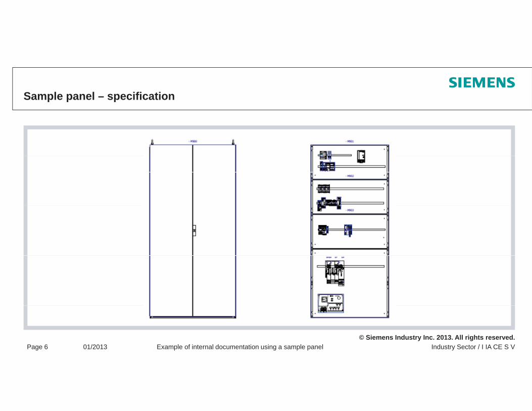
Sample panel – specification
© Siemens Industry Inc. 2013. All rights reserved.Industry Sector / I IA CE S VPage 6 01/2013 Example of internal documentation using a sample panel

General declaration of conformity according to ISO/IEC 17050
A declaration of conformity from a supplier is a form of confirmation of conformity, which:
fulfills the requirements of the market andgovernment bodies
in a way that inspires confidence.
Acceptance of a supplier's declaration of conformity could be further assisted if the details
on which the supplier bases his declaration
Recommendation if there is an export outside the
on which the supplier bases his declarationare kept ready in the form of a document and are made available upon request
© Siemens Industry Inc. 2013. All rights reserved.Industry Sector / I IA CE S VPage 7 01/2013 Example of internal documentation using a sample panel
Recommendation if there is an export outside theEEA (European Economic Area).

EC Declaration of Conformity
Example of an EC Declaration of Conformity:
In accordance with low-voltage directive 2006/95/ECIn accordance with EMC directive 2004/104/ECIn accordance with IEC 61439-1 & -2/EN 61439-1 & -2/VDE 0660 parts 600 1 & 2VDE 0660 parts 600-1 & -2
© Siemens Industry Inc. 2013. All rights reserved.Industry Sector / I IA CE S VPage 8 01/2013 Example of internal documentation using a sample panel

Circuit diagrams
© Siemens Industry Inc. 2013. All rights reserved.Industry Sector / I IA CE S VPage 9 01/2013 Example of internal documentation using a sample panel
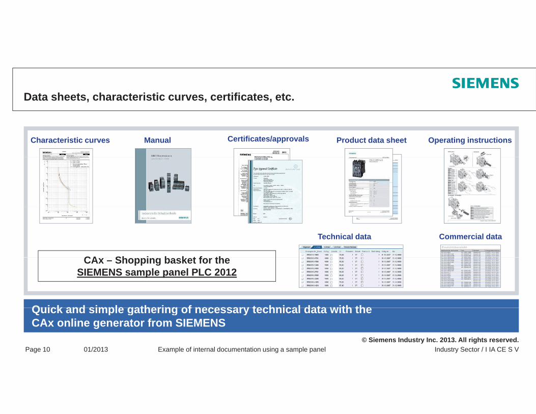
Data sheets, characteristic curves, certificates, etc.
Product data sheet Operating instructionsCharacteristic curves Manual Certificates/approvals
Commercial dataTechnical data
CA Sh i b k t f th
Quick and simple gathering of necessary technical data with the
CAx – Shopping basket for theSIEMENS sample panel PLC 2012
© Siemens Industry Inc. 2013. All rights reserved.Industry Sector / I IA CE S VPage 10 01/2013 Example of internal documentation using a sample panel
Quick and simple gathering of necessary technical data with theCAx online generator from SIEMENS
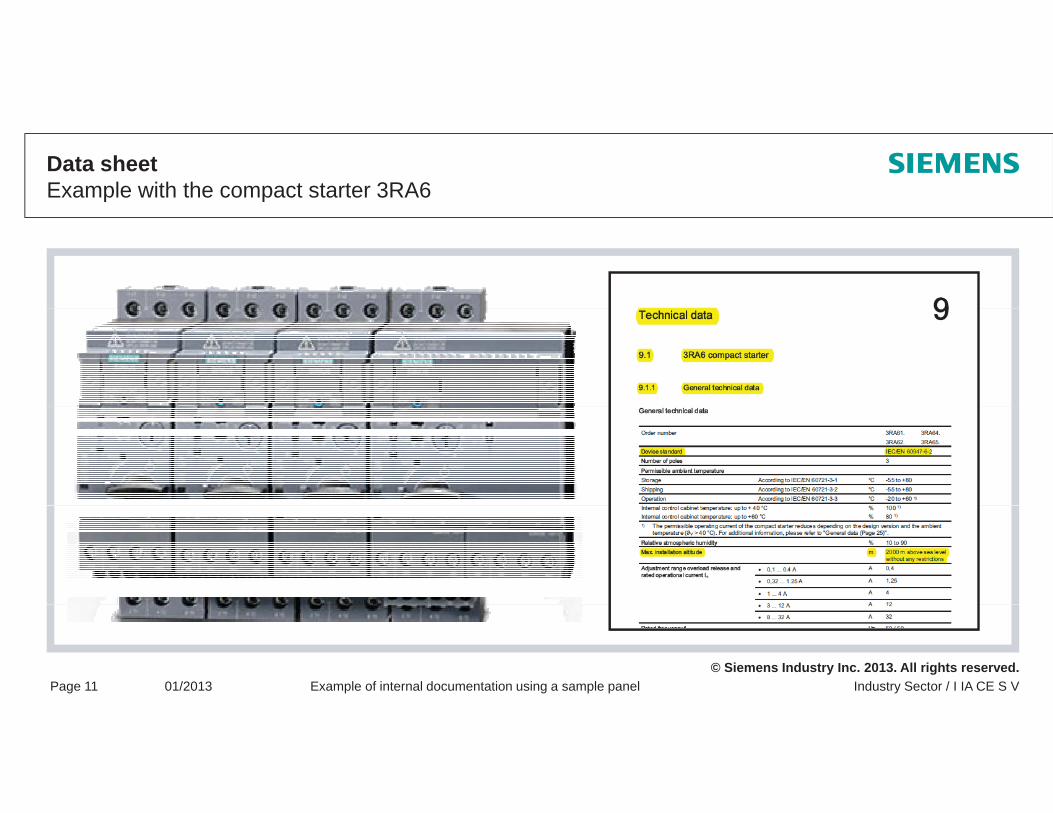
Data sheet Example with the compact starter 3RA6
© Siemens Industry Inc. 2013. All rights reserved.Industry Sector / I IA CE S VPage 11 01/2013 Example of internal documentation using a sample panel
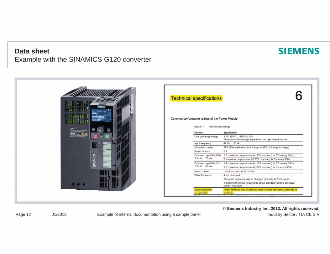
Data sheet Example with the SINAMICS G120 converter
© Siemens Industry Inc. 2013. All rights reserved.Industry Sector / I IA CE S VPage 12 01/2013 Example of internal documentation using a sample panel
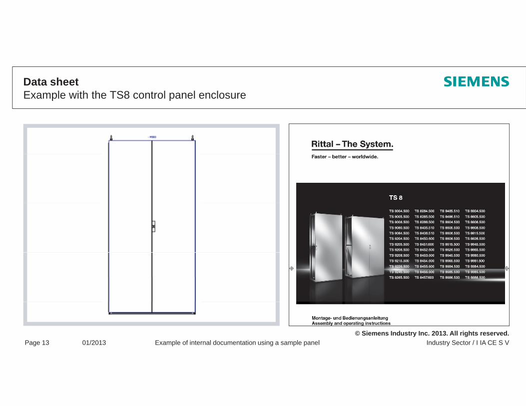
Data sheet Example with the TS8 control panel enclosure
© Siemens Industry Inc. 2013. All rights reserved.Industry Sector / I IA CE S VPage 13 01/2013 Example of internal documentation using a sample panel
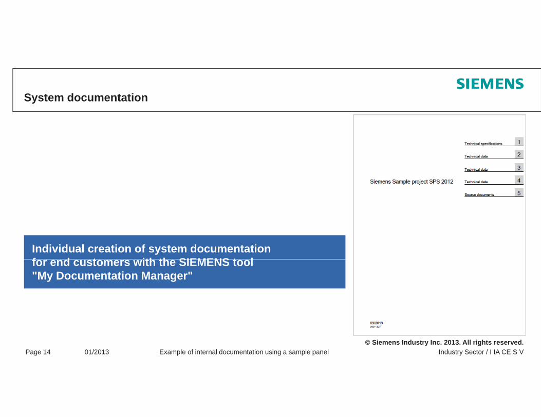
System documentation
Individual creation of system documentation f d t ith th SIEMENS t lfor end customers with the SIEMENS tool"My Documentation Manager"
© Siemens Industry Inc. 2013. All rights reserved.Industry Sector / I IA CE S VPage 14 01/2013 Example of internal documentation using a sample panel
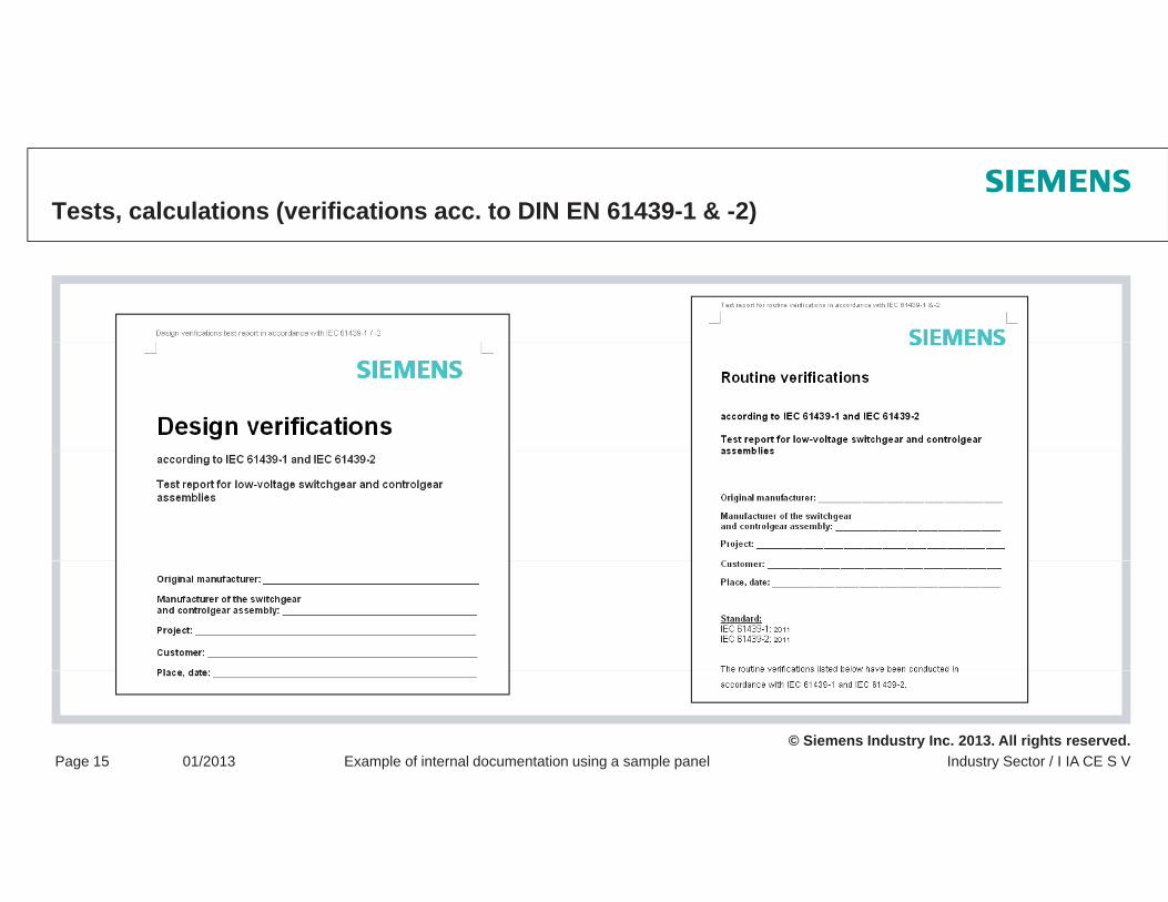
Tests, calculations (verifications acc. to DIN EN 61439-1 & -2)
© Siemens Industry Inc. 2013. All rights reserved.Industry Sector / I IA CE S VPage 15 01/2013 Example of internal documentation using a sample panel
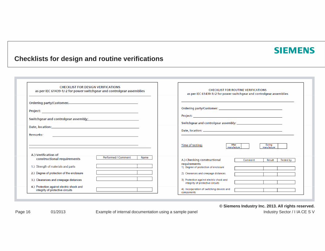
Checklists for design and routine verifications
© Siemens Industry Inc. 2013. All rights reserved.Industry Sector / I IA CE S VPage 16 01/2013 Example of internal documentation using a sample panel
Thank you for your attention!Any questions?
Note / Exclusion of liability
The typical circuit diagrams and interpretations of the standard are not binding and do not claim to be complete regarding configuration, equipment or any other eventuality. They do not represent any client-specific solutions and are only intended to offer assistance for typical tasksspecific solutions and are only intended to offer assistance for typical tasks.
Each person viewing this presentation is responsible for the correct operation of the products described. This presentation does not relieve you of your responsibility regarding safe handling when using, installing, operating, and maintaining the equipment.
By viewing this presentation you agree that Siemens cannot be made liable for possible damage beyondBy viewing this presentation you agree that Siemens cannot be made liable for possible damage beyond the above mentioned liability clause.We reserve the right to make changes and revisions to this informational documentation without prior announcement.
When writing these guidelines, a lot of tables and texts were lifted straight from the relevant standards. All g g gusers of this documentation must always check whether the items quoted are still up to date or not. The final decision about the appropriateness of applying the applicable standards must be made by the user of this documentation.
The reproduction of this presentation and its distribution, utilization or the dissemination of its contents to
© Siemens Industry Inc. 2013. All rights reserved.
The reproduction of this presentation and its distribution, utilization or the dissemination of its contents to third parties is not permitted.