swed1sh national grid unit, business area our reference
TRANSCRIPT
i,0, 2
018-
08-0
1
SVENSKAKRAFTNÄTSWED1SH NATIONAL GRID
UNIT, BUSINESS AREA OUR REFERENCENTL, Overhead Transmission Line; Grid Technology TR05-03-2E
DATE29 Januaiy 2020
.0NLB,NLP,NAL TECHNICAL GUIDELINE
REVISION APPROVED4 TD
Overhead transmission linesManufacturing of supports
IntroductionThese guidelines describe the requirements on manufacture of supports for overhead transmission lines and cover manufacture and installation. The guidelines intend to guarantee satisfactory performance of supports during the service lifetime of the overhead line and shall be used at purchasing of supports
TECHNICAL GUIDELINE 29 January 2020 TR05-03-2E rev 4
2 (25)
TECHNICAL GUIDELINE 29 January 2020 TR05-03-2E rev 4
Revision Notes Change notes Date
1 TR05-03 har delats upp i två delar och ersatts av TR05-03-2 Tillverkning (denna del) samt TR05-03-1 Konstruktion
2017-07-04
2 Kapitelhänvisningar reviderade. Kapitel 4.3 SS-EN 50341 -2 införd . kapitel 5.4.1. text under tabell 5A omredigerad. Kapitel 5.9.2. 0,14% ändrat till 0,15% för Fe/Zn95
2017-09-05
3 1. Referenser uppdaterade. 5.2 Utförandekrav förtydligade. 5.3.1 Spårbarhetskrav förtydligat. 5.4.1 Tabell uppdaterad och krav på Z-35 förtydligat. 5.5 Hänvisning till EN ISO 13920 införd och toleranser justerade, krav på krokighet flyttad från kap 7. 5.9.2 Tabell 5F justerad. 5,11 Kapitel om kontrollnivå på svetsar infört. 5.11.8 Text justerad. 5.11.9 Text justerad. 7.3 toleranskrav för krokighet flyttad till 5.5
2018-12-03
4 Technical guideline translated to English. 5.2 EXC regarding traceability revised. 5.11.4 Scope of RT and text revised. 5.10.2 Marking bolts revised. 5.11.7 Text revised. OBS! Drawing 404 0000 is withdrawn.
2020-01-29
3 (25)
TECHNICAL GUIDELINE 29 January 2020 TR05-03-2E rev 4
Content
1 References ........................................................................................................... 5
2 Scope .................................................................................................................... 7
3 Definitions ........................................................................................................... 7
4 Wooden poles ...................................................................................................... 8
4.1 General 8
4.2 Dimensions 8
Table 4A 8
4.3 Quality requirement 9
4.4 Impregnation 9
4.5 Marking 9
4.6 Glue laminated poles 10
5 Manufacture of support components in steel ................................................. 10
5.1 Quality system 10
5.2 Execution class 10
5.3 Quality documentation 10
5.3.1 Delivery of quality documentation before manufacturing
starts 10
5.3.2 Delivery of quality documentation during manufacture 11
5.4 Material 11
5.4.1 Structural steel 11
5.4.2 Stay wire 12
5.5 Manufacturing tolerances 12
5.6 Machining 14
5.6.1 Cutting 14
5.6.2 Straightening and bending 14
5.6.3 Holes 14
5.7 Welding 14
5.7.1 Welding of structures which are to be hot-dip galvanised 15
5.8 Marking 15
5.8.1 General 15
4 (25)
TECHNICAL GUIDELINE 29 January 2020 TR05-03-2E rev 4
5.8.2 Structures with bolted connections 15
5.8.3 Welded structures 15
5.9 Surface treatment 16
5.9.1 Surface quality 16
5.9.2 Hot-dip galvanising when manufacturing 17
5.10 Bolted connections 18
5.10.1 Surface treatment of bolted connections 18
5.10.2 Svenska kraftnät SK bolts 18
5.11 Inspection and testing 19
5.11.1 Materials 19
5.11.2 Dimensions 19
5.11.3 Machining 19
5.11.4 Welding 20
5.11.5 Bolts and nuts 20
5.11.6 Surface treatment 20
5.11.7 Shop assembly 21
5.11.8 Support test 21
6 Delivery ............................................................................................................. 22
6.1 Quality documentation 22
6.2 Transportation and storage 22
6.2.1 Loading and unloading 22
6.2.2 Transport 22
6.2.3 Storage of steel structures 22
6.2.4 Storage of impregnated wood 22
7 Installation ........................................................................................................ 23
7.1 General information 23
7.2 Repair of hot-dip galvanisation 23
7.2.1 Major damage to hot-dip galvanisation 23
7.3 Installation tolerances 24
7.4 Stay 24
7.5 Bolted connections 24
7.6 Tightening torque 25
5 (25)
TECHNICAL GUIDELINE 29 January 2020 TR05-03-2E rev 4
1 References NTR Document no. 1:2013 Nordic wood preservation grades and product
requirements for preservative-treated wood Part 1: Pine and other permeable softwoods
NTR Document no. 3:2013 Nordic regulations for quality control of preservative-
treated wood Part 1: Pine and other permeable softwoods ISO 965-4 General purpose metric screw threads – Tolerances –
Part 4: Limits of sizes for hot-dip galvanised external screw threads to mate with internal screw threads tapped with tolerance position H or G after galvanising
SS-EN 1090-1 Execution of steel structures and aluminium structures
– Part 1: Requirements for conformity assessment of structural components
SS-EN 1090-2 Execution of steel structures and aluminium structures
— Part 2: technical requirement for steel structures SS-EN ISO 1461 Hot-dip galvanised coatings on fabricated iron and steel
articles — Specifications and test methods EN ISO 3166-1 Codes for the representation of names of countries and
their subdivisions – Part 1: Country codes EN ISO 3834-2 Quality requirements for fusion welding of metallic
materials – Part 2: Comprehensive quality requirements EN ISO 4014 Hexagon head bolts – Product grades A and B EN ISO 4032 Hexagon head bolts (style 1) – Product grades A and B EN ISO 4759-3 Tolerances for fasteners – Part 3: Washers for bolts,
screws and nuts – Product grades A and C EN ISO 5817 Welding – Fusion welded joints in steel, nickel, titanium
and their alloys (beam welding excluded) – Quality levels for imperfections (ISO 5817:2014)
EN ISO 7438 Metallic materials – Bend test ISO 8501-1 Preparation of steel substrates before application of
paints and related products – Visual assessment of surface cleanliness – Part 1: Rust grades and preparation grades of uncoated steel substrates and of steel substrates after overall removal of previous coatings
ISO 8501-3 Preparation of steel substrates before application of
paints and related products – Visual assessment of surface cleanliness – Part 3: Preparation grades of welds, cut edges and other areas with surface imperfections
EN ISO 9001 Quality management systems – Requirements
6 (25)
TECHNICAL GUIDELINE 29 January 2020 TR05-03-2E rev 4
EN 10025-1 Hot rolled products of structural steels – Part 1: General technical delivery conditions
EN 10025-2 Hot rolled products of structural steels – Part 2:
Technical delivery conditions for non-alloy structural steels
EN 10025-3 Hot rolled products of structural steels – Part 3:
Technical delivery conditions for normalised/normalised rolled weldable fine grain structural steels
EN 10025-4 Hot rolled products of structural steels – Part 4:
Technical delivery conditions for thermomechanical rolled weldable fine grain structural steels
EN 10149-2 Hot rolled flat products made of high yield strength
steels for cold forming – Part 2 Delivery conditions for thermomechanically rolled steels
EN 10204 Metallic products – Types of inspection documents EN 10210-1 Hot finished structural hollow sections of non-alloy and
fine grain steels – Part 1: Technical delivery conditions EN 10219-1 Cold formed welded structural hollow sections of non-
alloy and fine grain steels – Part 1: Technical delivery conditions
EN 10244 Steel wire and wire products – Non-ferrous metallic
coatings on steel wire – Part 2: Zinc or zinc alloy coatings
EN ISO 10684 Fasteners – Hot-dip galvanised coatings EN ISO 12944-2 Paints and varnishes – Corrosion protection of steel
structures by protective paint systems – Part 2: Classification of environments
EN ISO 13920 Welding - General tolerances for welded constructions -
Dimensions for length and angles - Shape and position (ISO 13920:1996)
EN 14229 Structural timber – Wooden poles for overhead lines
EN 14399-3 Fasteners – High-strength structural bolting assemblies
for preloading – Part 3: System HR – Hexagon bolt and nut assemblies
EN ISO 14713-2 Zinc coatings – Guidelines and recommendations for the
protection against corrosion of iron and steel in structures – Part 2: Hot-dip galvanising
EN 15048-1 Fasteners – Non-preloaded structural bolting
assemblies – Part 1: General requirements EN 15048-2 Fasteners – Non-preloaded structural bolting
assemblies – Part 2: Suitability test
7 (25)
TECHNICAL GUIDELINE 29 January 2020 TR05-03-2E rev 4
EN ISO 15609 Specification and qualification of welding procedures for
metallic materials – Welding procedure specification (WPS)
EN ISO 15612 Specification and qualification of welding procedures for
metallic materials – Qualification by adoption of a standard welding procedure
EN ISO 15613 Specification and qualification of welding procedures for
metallic materials – Qualification based on pre-production welding test
EN ISO 15614-1 Specification and qualification of welding procedures for
metallic materials – Welding procedure test – Part 1: Arc and gas welding of steels and arc welding of nickel and nickel alloys
EN 50341-1 Overhead electrical lines exceeding AC 1 kV General
requirements – Common specifications
vSS-EN 50341-2-18 Overhead electrical lines exceeding AC 1 kV National
Normative Aspects (NNA) for Sweden
IEC 60652 Loading tests on overhead line structures TR05-04E Svenska kraftnät Technical guidelines - Conductors
2 Scope
These technical guidelines comprise manufacturing regulations for supports in
steel and wood for transmission lines.
3 Definitions
Sleeper
Designation for beams intended to hold rails together for rail traffic. Here it denotes a
horizontally oriented beam in wood, steel, concrete or other material which is buried
under the ground and anchors a structure through covering with a mass of earth which
forms an abutment.
Support
Structure above foundation intended to support overhead line.
8 (25)
TECHNICAL GUIDELINE 29 January 2020 TR05-03-2E rev 4
Steel tower
Support made mainly of steel.
Wooden pole
Support where the legs, and in some cases other parts, are made of wood. The support
legs are made out of a whole trunk that is simply cut and debarked.
4 Wooden poles
4.1 General Wooden poles/sleepers are preferably made of pine (Pinus sylvestris) and shall meet
the requirements in SS EN 14229:2010.
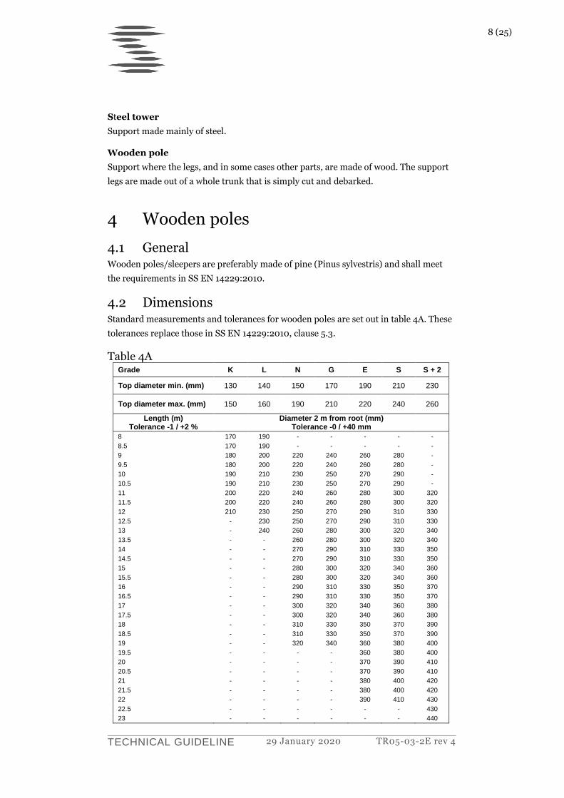
4.2 Dimensions Standard measurements and tolerances for wooden poles are set out in table 4A. These
tolerances replace those in SS EN 14229:2010, clause 5.3.
Table 4A Grade K L N G E S S + 2
Top diameter min. (mm) 130 140 150 170 190 210 230
Top diameter max. (mm) 150 160 190 210 220 240 260
Length (m) Tolerance -1 / +2 %
Diameter 2 m from root (mm) Tolerance -0 / +40 mm
8 170 190 - - - - -
8.5 170 190 - - - - -
9 180 200 220 240 260 280 -
9.5 180 200 220 240 260 280 -
10 190 210 230 250 270 290 -
10.5 190 210 230 250 270 290 -
11 200 220 240 260 280 300 320
11.5 200 220 240 260 280 300 320
12 210 230 250 270 290 310 330
12.5 - 230 250 270 290 310 330
13 - 240 260 280 300 320 340
13.5 - - 260 280 300 320 340
14 - - 270 290 310 330 350
14.5 - - 270 290 310 330 350
15 - - 280 300 320 340 360
15.5 - - 280 300 320 340 360
16 - - 290 310 330 350 370
16.5 - - 290 310 330 350 370
17 - - 300 320 340 360 380
17.5 - - 300 320 340 360 380
18 - - 310 330 350 370 390
18.5 - - 310 330 350 370 390
19 - - 320 340 360 380 400
19.5 - - - - 360 380 400
20 - - - - 370 390 410
20.5 - - - - 370 390 410
21 - - - - 380 400 420
21.5 - - - - 380 400 420
22 - - - - 390 410 430
22.5 - - - - - - 430
23 - - - - - - 440
9 (25)
TECHNICAL GUIDELINE 29 January 2020 TR05-03-2E rev 4
4.3 Quality requirement SS-EN 50341-2-18 (NNA) clause 7.5 and SS-EN 14229 clause 5 apply to the timber’s
quality, with the addition that the core shall be maximum of 2/3 of the pole’s diameter
and that when processing timber for poles, the branches shall be cut off in the direction
from the root towards the top and with flush and flat surfaces. Wooden poles shall in
addition be sawn even at both ends and shall be completely debarked. This means that,
besides all bark, the outermost layer of wood (1 or 2 annual rings) shall be removed.
4.4 Impregnation Wooden poles/sleepers shall be impregnated in accordance with NTR Document
no. 1 and NTR Document no. 3.
Wooden poles /sleepers shall be pressure-treated with MT-creosote oil WEI type B
according to the requirements for Wood preservation grade A in NTR Document
no. 3:2013, with the amendment that AQL = 0.65% shall apply to poles for
overhead lines. This means that no tests with insufficient penetration according to
table 10.4 in NTR Document no. 3:2013 are permitted. Penetration is to be checked
by means of a drilling test and documented in a test record. The record shall be
included in the quality documentation.
4.5 Marking Poles shall be furnished on delivery with a marking which facilitates
identification/classification of each individual pole in connection with inspection, and
also facilitates destruction in the future.
The marking shall be positioned 4 m from the root end and be clear and permanent.
This can be achieved by placing all information on one or a number of signs made of
permanent material that will last for the pole’s expected service life. The sign(s) shall be
attached in such a way that it/they cannot be damaged or fall off when the pole is
handled. All other markings of poles shall be kept well away from the above marking.
The marking shall contain the following:
CE marking according to SS-EN 14229, Annex ZA.
NTR marking according to NTR document.
Pole class and length (for example E14).
Kind of wood and origin in code form. (Kind of wood according to SS-EN 14229, table E.1 and country code according to SS-EN ISO 3166 1.)
Year (two final digits) when the pole was produced, impregnated.
Wood preservative.
10 (25)
TECHNICAL GUIDELINE 29 January 2020 TR05-03-2E rev 4
Manufacturer in code form or plain text; name shall
always be in plain text when wood is imported.
4.6 Glue laminated poles SS-EN 50341-2-18, clause 7.8/SE.1.1 applies to glue-laminated wood. Glue-laminated
wood is impregnated according to SS-EN 50341-2-18, clause 7.9.7/SE.1.
5 Manufacture of support components in steel
All manufacturing of components in steel shall be performed according to SS-EN
1090-2, except the amendments in this technical guideline.
5.1 Quality system Manufacturers of support components in steel shall have a management system for
quality based on EN ISO 9001 and a production control system based on SS-EN 1090-1.
A certificate for SS-EN 1090-2 shall be valid for the manufacture of steel structures
according to execution class EXC3 or EXC4.
5.2 Execution class According to SS-EN 1090-2, the execution class shall be EXC2, with the exception to
that EXC3 is applicable to welds. This means that acceptance level B is applicable to the
execution of welds in accordance with EN ISO 5817.
5.3 Quality documentation All quality documentation related to the work shall be available to the client’s
representative until the work is completed. All documentation, including underlying
documents, shall be in Swedish or English.
5.3.1 Delivery of quality documentation before manufacturing starts
Time schedule
Time schedule shall include dates for tests and deliveries. The document shall be
updated and presented to Svenska kraftnät on an ongoing basis.
Organization plan
Organization plan shall contain name of key persons, their duties and responsibilities
during the project, position, as well as routes for communication between them.
Inspection schedule
An inspection schedule shall be compiled based on manufacturing drawings for each
structure.
11 (25)
TECHNICAL GUIDELINE 29 January 2020 TR05-03-2E rev 4
Identification of material and traceability documents
Svenska kraftnät provides a documentation template for presentation of products and
consumables included in the delivery.
The following information shall be summarized in one document:
Profile type
Steel type
Heat/Batch
Certificate number
Quantity (m/kg)
Manufacturer/Country
Type of document
This document shall be enclosed with each individual delivery, and a summarized
document for all deliveries shall be provided when deliveries are completed.
Records for qualification of welding procedures (WPOR)
Records for qualification of welding procedures according to EN ISO 15612, EN ISO
15613 or EN ISO 15614.
Welding procedure specification (WPS)
Welding procedure specification according to EN ISO 15609 for welds in the structures
that are to be delivered.
5.3.2 Delivery of quality documentation during manufacture
Inspection test records
Records from inspections/tests according to inspection plan.
Deviation reports
All deviations shall be detailed in reports.
5.4 Material
5.4.1 Structural steel
Structural steel shall be in accordance with the standards specified in table 5A.
Table 5A
Standard Type of steel
EN 10025-1 EN 10025-2 EN 10025-3 EN 10025-4 EN 10210-1 EN 10219-1 EN 10149-2
General Non-alloy steel Normalised fine grain structural steels Thermomechanical rolled fine grain structural steel Non-alloy steel and fine grain structural steel for heat-treated pipes Non-alloy steel and fine grain structural steel for cold-treated pipes High strength steels for cold forming
12 (25)
TECHNICAL GUIDELINE 29 January 2020 TR05-03-2E rev 4
For bars and girders where steel S355N or S355J2+N is specified on the drawing, this
may be replaced by S355J2. Any change in steel grade shall be approved by Svenska
kraftnät.
Z-35 steel shall be supplied with option 4, according to 10025-1 and with a reported
special process in order to achieve improved properties in the thickness direction. Only
the designation S355N+Z35 will be accepted on inspection certificates. Ultrasonic
inspection may only be performed for this steel type by the person who is responsible
for the manufacturing process.
All steel shall be supplied with inspection certificate type 3.1 according to EN 10204.
Steel material shall be suitable for hot-dip galvanising. See clause 5.9.2.
Rust on steel surface shall not extend further than that specified in EN ISO 8501-1
degree of rusting B.
The material shall be marked with a system specified by the manufacturer, consisting of
paint or text, for identification of the material quality.
5.4.2 Stay wire
Stay wire shall be in accordance with Svk TR05-04E.
5.5 Manufacturing tolerances Measurements shall be in strict conformity with the details stated in each specific case.
Measurements that are dependent on the structure’s position and base shall generally
apply when the structure is placed horizontally on a flat and stable surface.
Measurements apply at room temperature prior to surface coating. However,
measurements for threads refer to measurements after hot-dip galvanising. Hot-dip
galvanised external thread shall have measurements according to ISO 965-4 before hot-
dip galvanising.
The following tolerances generally apply unless stated otherwise on the drawing.
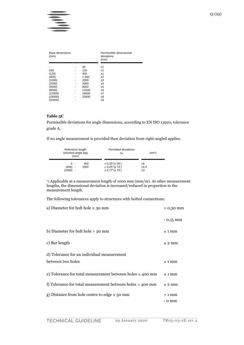
Table 5B
Permissible dimensional deviations for linear dimensions for welded structures,
according to EN ISO 13920, tolerance grade A.
13 (25)
TECHNICAL GUIDELINE 29 January 2020 TR05-03-2E rev 4
Base dimensions (mm)
Permissible dimensional deviations (mm)
- (30) (120) (400) (1000) (2000) (4000) (8000) (12000) (16000) (20000)
- - - - - - - - - - -
30 120 400 1 000 2000 4000 8000 12000 16000 20000
±1 ±1 ±1 ±2 ±3 ±4 ±5 ±6 ±7 ±8 ±9
Table 5C
Permissible deviations for angle dimensions, according to EN ISO 13920, tolerance
grade A.
If no angle measurement is provided then deviation from right-angled applies.
Reference length (shortest angle leg)
(mm)
Permitted deviations
mm*)
0 (400)
(1000)
- - -
400 1000
± 0,33°(± 20’) ± 0,25°(± 15’) ± 0,17°(± 10’)
±6 ±4.5 ±3
*) Applicable at a measurement length of 1000 mm (mm/m). At other measurement lengths, the dimensional deviation is increased/reduced in proportion to the measurement length. The following tolerances apply to structures with bolted connections: a) Diameter for bolt hole ≤ 30 mm + 0,30 mm
- 0,15 mm
b) Diameter for bolt hole > 30 mm ± 1 mm
c) Bar length ± 2 mm
d) Tolerance for an individual measurement
between two holes ± 1 mm
e) Tolerance for total measurement between holes ≤ 400 mm ± 1 mm
f) Tolerance for total measurement between holes > 400 mm ± 2 mm
g) Distance from hole centre to edge ≤ 50 mm + 1 mm
- 0 mm

14 (25)
TECHNICAL GUIDELINE 29 January 2020 TR05-03-2E rev 4
h) Distance from hole centre to edge > 50 mm ± 1 mm
i) Curvature of support legs, girders or individual bars shall not exceed 0,0015 of
the length.
5.6 Machining
5.6.1 Cutting
Cutting shall be performed according to SS-EN 1090-2, clause 6.4. See also 5.9.1 in this
document.
5.6.2 Straightening and bending
Straightening and bending shall be adapted to the relevant type of steel and executed
with methods which have as little effect on the properties of the material as possible.
Instructions for different types of steel can be found in the relevant standard or
obtained from the steel manufacturer.
For forming in a cold state it is important not to go below the minimum bending radius
stated in the relevant steel standard. If bending with smaller radius in a cold state is
required, then a bend test shall be performed, see clause 5.11.3.
For forming with heating method the temperature shall be adapted to the relevant type
of steel. Instructions and recommendations can be found in the relevant standard or
obtained from the steel manufacturer.
5.6.3 Holes
Holes shall be executed according to SS EN-1090 2, clause 6.6.3, with the following
additions:
Punching is not permitted for material thicknesses in excess of 13 mm. In other cases,
holes shall be drilled or punched that are at least 3 mm smaller than nominal hole
diameter, and then reamed or drilled to the final diameter.
Holes with diameter smaller than 35 mm shall be drilled or punched.
Edges of holes shall be machined so that they meet the requirements for surface finish
in clause 5.9.1.
Incorrectly drilled holes shall neither completely nor partially filled through welding.
5.7 Welding Welds may only occur where specified and shall then be executed and checked in
conformity with clause 7 in SS-EN 1090-2. The quality requirements according to EN
ISO 3834 part 2 “Comprehensive quality requirements” apply to welds. For details, see
clause 5.2.
15 (25)
TECHNICAL GUIDELINE 29 January 2020 TR05-03-2E rev 4
5.7.1 Welding of structures which are to be hot-dip galvanised
Pockets and gaps, which can constitute acid traps is not allowed.
5.8 Marking
5.8.1 General
These marking instructions apply unless indicated otherwise on the drawing or in
another construction document.
All steel parts shall be marked. Based on marking designation, each individual part
shall be traceable to its manufacturing drawing. A description of the marking
designation shall be drawn up by the manufacturer and included in the documentation.
Marking prior to surface coating shall be executed through mechanical punching with
10 mm high characters on angle bars, flat rolled steel and plate up to and including 8
mm material thickness. With material thicknesses greater than 8 mm, including U and
HE girders, marking shall be executed with 14-16 mm high characters. Marking shall be
executed and positioned in such a way that there is no risk of fracture indications and at
least 10 mm from the edge.
On bars and girders, marking shall be positioned 100 150 mm from the last hole in the
group of holes at one end of the outwardly turned side. If this area is not suitable for
marking, it shall be placed further in towards the bar’s or the girder’s centre. For main
bar for tower legs, marking shall be positioned in the lower end and for main bar for
crossarm in the connection end or if it is a crossarm without connections at the
arbitrary end. In certain cases the drawing indicates where the marking is to be placed.
Punched designations shall be separated from each other by a point.
If punched marking is indistinct after galvanisation, the text shall be made clear by
means of paint, which provides a good contrast and has good durability (e.g. fast-drying
PVC paint). Marking with alcohol based marker pens is not permitted.
The marking shall be positioned on the side in the structure that is turned outwards and
so that it is visible after assembly.
5.8.2 Structures with bolted connections
Parts for structures which are to be connected with bolted joints shall be marked in
such a way that the individual part can be unambiguously identified on respective
drawing.
5.8.3 Welded structures
Welded units, which are to be fitted together with each other, shall have
designations of make on the outwardly turned side alongside the joint in such a way
that the markings on the different units are positioned central to each other, i.e. in
line with each other.
16 (25)
TECHNICAL GUIDELINE 29 January 2020 TR05-03-2E rev 4
5.9 Surface treatment All steel shall be hot-dip galvanised unless indicated otherwise on the drawing or in
another construction document.
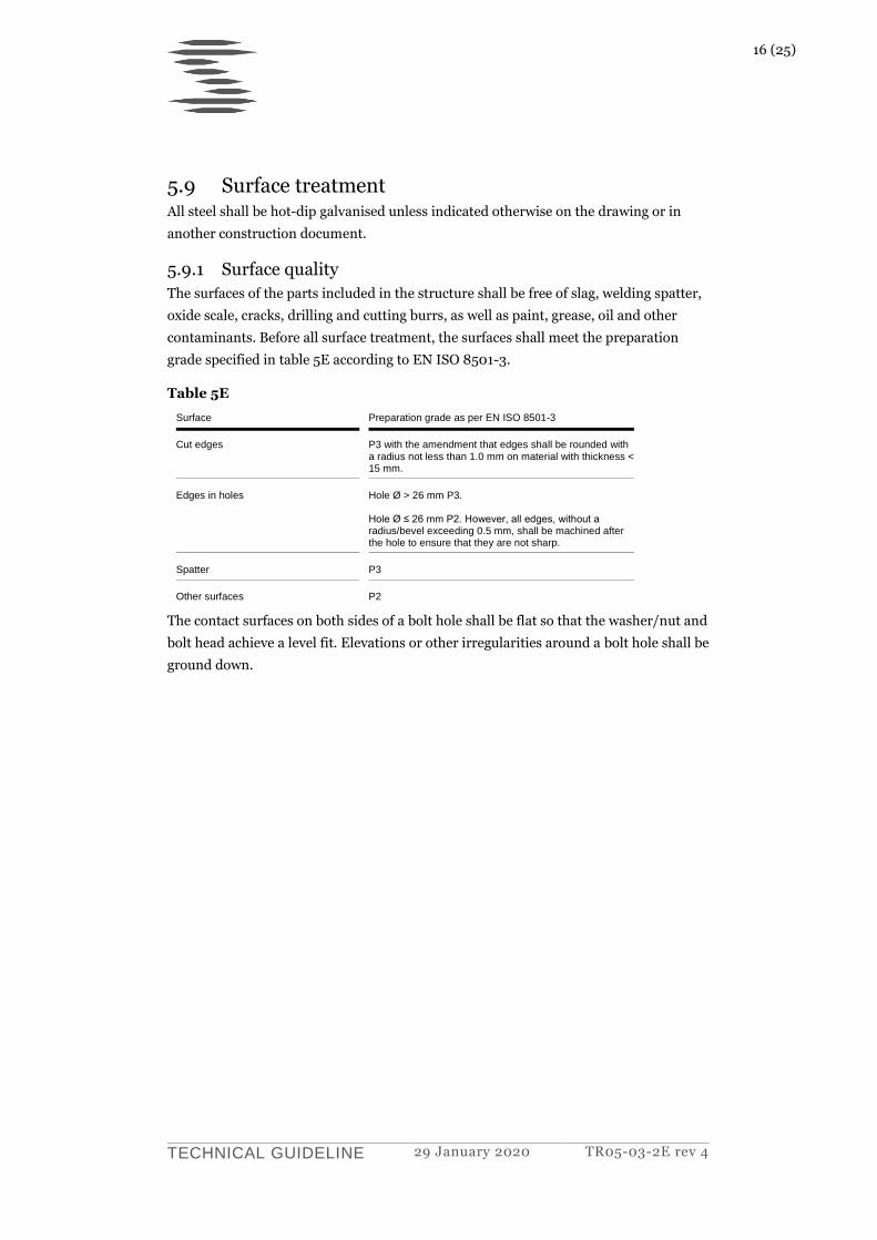
5.9.1 Surface quality
The surfaces of the parts included in the structure shall be free of slag, welding spatter,
oxide scale, cracks, drilling and cutting burrs, as well as paint, grease, oil and other
contaminants. Before all surface treatment, the surfaces shall meet the preparation
grade specified in table 5E according to EN ISO 8501-3.
Table 5E
Surface Preparation grade as per EN ISO 8501-3
Cut edges P3 with the amendment that edges shall be rounded with a radius not less than 1.0 mm on material with thickness < 15 mm.
Edges in holes Hole Ø > 26 mm P3. Hole Ø ≤ 26 mm P2. However, all edges, without a radius/bevel exceeding 0.5 mm, shall be machined after the hole to ensure that they are not sharp.
Spatter P3
Other surfaces P2
The contact surfaces on both sides of a bolt hole shall be flat so that the washer/nut and
bolt head achieve a level fit. Elevations or other irregularities around a bolt hole shall be
ground down.
17 (25)
TECHNICAL GUIDELINE 29 January 2020 TR05-03-2E rev 4
5.9.2 Hot-dip galvanising when manufacturing
The steel material shall be suitable for hot-dip galvanising. See also SS-EN ISO 1461,
Annex NA.
The instructions in EN ISO 14713-2, clauses 4.2 and 6.2 shall be taken into
consideration for pre-treatment.
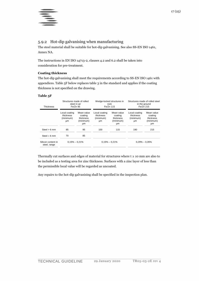
Coating thickness
The hot-dip galvanising shall meet the requirements according to SS-EN ISO 1461 with
appendices. Table 5F below replaces table 3 in the standard and applies if the coating
thickness is not specified on the drawing.
Table 5F
Thickness
Structures made of rolled steel in air Fe/Zn 95
Wedge-locked structures in rock
Fe/Zn 115
Structures made of rolled steel in the ground
Fe/Zn 215
Local coating thickness (minimum)
µm
Mean value coating
thickness (minimum)
µm
Local coating thickness (minimum)
µm
Mean value coating
thickness (minimum)
µm
Local coating thickness
(minimum) µm
Mean value coating
thickness (minimum)
µm
Steel > 6 mm 85 95 100 115 190 215
Steel 6 mm 70 85
Silicon content in steel, range
0,15% – 0,21% 0,15% – 0,21% 0,29% – 0,35%
Thermally cut surfaces and edges of material for structures where t ≥ 10 mm are also to
be included as a testing area for zinc thickness. Surfaces with a zinc layer of less than
the permissible local value will be regarded as uncoated.
Any repairs to the hot-dip galvanising shall be specified in the inspection plan.
18 (25)
TECHNICAL GUIDELINE 29 January 2020 TR05-03-2E rev 4
5.10 Bolted connections
5.10.1 Surface treatment of bolted connections
Bolts shall be hot-dip galvanised according to SS EN ISO 10684.
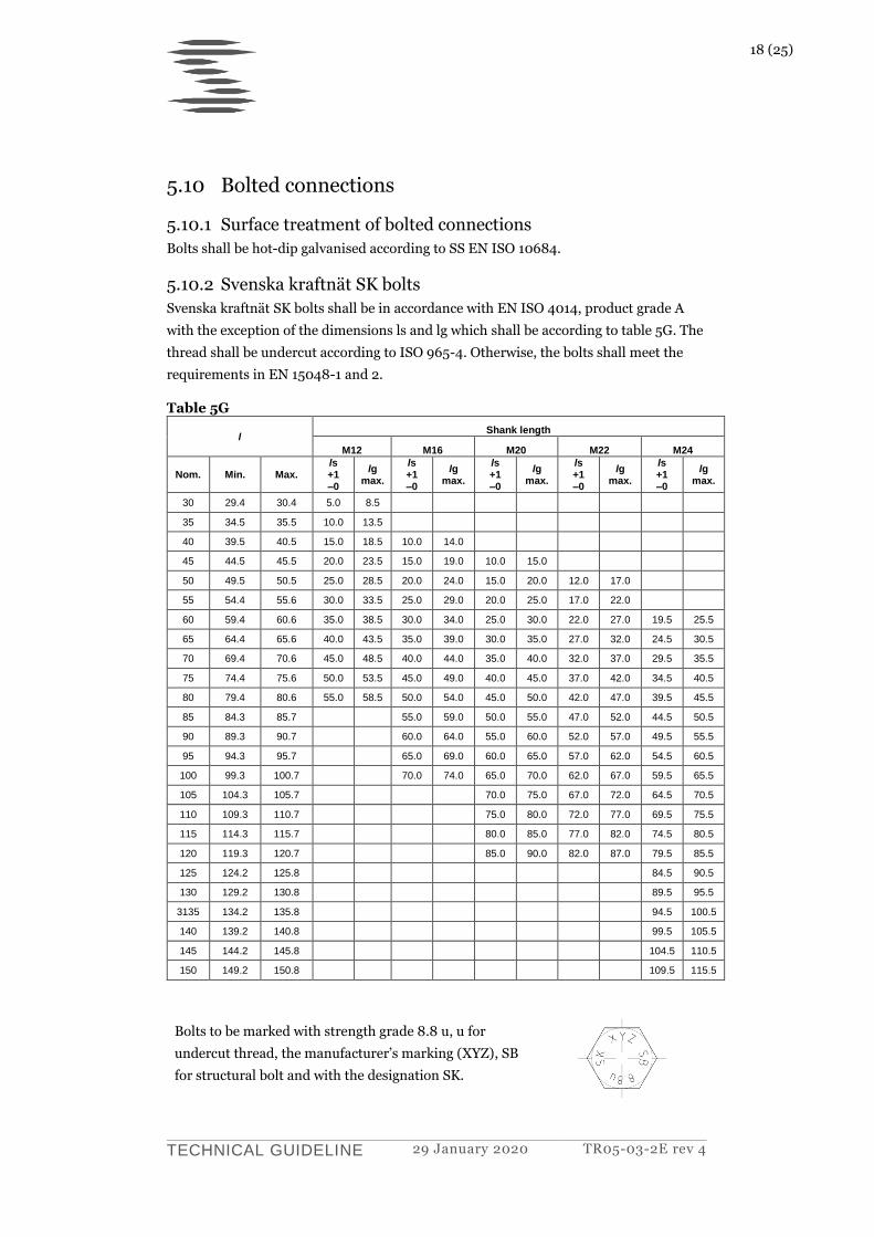
5.10.2 Svenska kraftnät SK bolts
Svenska kraftnät SK bolts shall be in accordance with EN ISO 4014, product grade A
with the exception of the dimensions ls and lg which shall be according to table 5G. The
thread shall be undercut according to ISO 965-4. Otherwise, the bolts shall meet the
requirements in EN 15048-1 and 2.
Table 5G
l Shank length
M12 M16 M20 M22 M24
Nom. Min. Max. ls +1 –0
lg max.
ls +1 –0
lg max.
ls +1 –0
lg max.
ls +1 –0
lg max.
ls +1 –0
lg max.
30 29.4 30.4 5.0 8.5
35 34.5 35.5 10.0 13.5
40 39.5 40.5 15.0 18.5 10.0 14.0
45 44.5 45.5 20.0 23.5 15.0 19.0 10.0 15.0
50 49.5 50.5 25.0 28.5 20.0 24.0 15.0 20.0 12.0 17.0
55 54.4 55.6 30.0 33.5 25.0 29.0 20.0 25.0 17.0 22.0
60 59.4 60.6 35.0 38.5 30.0 34.0 25.0 30.0 22.0 27.0 19.5 25.5
65 64.4 65.6 40.0 43.5 35.0 39.0 30.0 35.0 27.0 32.0 24.5 30.5
70 69.4 70.6 45.0 48.5 40.0 44.0 35.0 40.0 32.0 37.0 29.5 35.5
75 74.4 75.6 50.0 53.5 45.0 49.0 40.0 45.0 37.0 42.0 34.5 40.5
80 79.4 80.6 55.0 58.5 50.0 54.0 45.0 50.0 42.0 47.0 39.5 45.5
85 84.3 85.7 55.0 59.0 50.0 55.0 47.0 52.0 44.5 50.5
90 89.3 90.7 60.0 64.0 55.0 60.0 52.0 57.0 49.5 55.5
95 94.3 95.7 65.0 69.0 60.0 65.0 57.0 62.0 54.5 60.5
100 99.3 100.7 70.0 74.0 65.0 70.0 62.0 67.0 59.5 65.5
105 104.3 105.7 70.0 75.0 67.0 72.0 64.5 70.5
110 109.3 110.7 75.0 80.0 72.0 77.0 69.5 75.5
115 114.3 115.7 80.0 85.0 77.0 82.0 74.5 80.5
120 119.3 120.7 85.0 90.0 82.0 87.0 79.5 85.5
125 124.2 125.8 84.5 90.5
130 129.2 130.8 89.5 95.5
3135 134.2 135.8 94.5 100.5
140 139.2 140.8 99.5 105.5
145 144.2 145.8 104.5 110.5
150 149.2 150.8 109.5 115.5
Bolts to be marked with strength grade 8.8 u, u for
undercut thread, the manufacturer’s marking (XYZ), SB
for structural bolt and with the designation SK.
19 (25)
TECHNICAL GUIDELINE 29 January 2020 TR05-03-2E rev 4
Nuts
Nuts shall have strength grade 8 and meet the requirements in EN 15048-1 and 2 as
well as EN ISO 4032.
The threads of the nuts shall be protected so that they can be stored outdoors for 6
months without corrosion appearing on the threads.
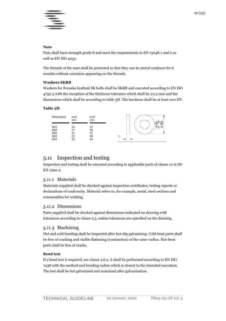
Washers SKRB
Washers for Svenska kraftnät SK bolts shall be SKRB and executed according to EN ISO
4759-3 with the exception of the thickness tolerance which shall be ±0.5 mm and the
dimensions which shall be according to table 5H. The hardness shall be at least 200 HV.
Table 5H
Dimensions ø d1 mm
ø d2 mm
M12 M16 M20 M22 M24
13 17 21 23 25
24 30 37 39 44
5.11 Inspection and testing Inspection and testing shall be executed according to applicable parts of clause 12 in SS-
EN 1090-2.
5.11.1 Materials
Materials supplied shall be checked against inspection certificates, testing reports or
declarations of conformity. Material refers to, for example, metal, steel sections and
consumables for welding.
5.11.2 Dimensions
Parts supplied shall be checked against dimensions indicated on drawing with
tolerances according to clause 5.5, unless tolerances are specified on the drawing.
5.11.3 Machining
Hot and cold bending shall be inspected after hot-dip galvanising. Cold-bent parts shall
be free of cracking and visible flattening (contraction) of the outer radius. Hot-bent
parts shall be free of cracks.
Bend test
If a bend test is required, see clause 5.6.2, it shall be performed according to EN ISO
7438 with the method and bending radius which is closest to the intended execution.
The test shall be hot galvanised and examined after galvanisation.
20 (25)
TECHNICAL GUIDELINE 29 January 2020 TR05-03-2E rev 4
An approved bend test shall be free of cracking and visible flattening (contraction) of
the outer radius. The test report from the bend test shall be included in the quality
documentation.
5.11.4 Welding
Inspection and testing of welds shall be executed according to clause 12.4 in SS-EN
1090-2.
Weld inspection level and methods
The level of non-destructive testing according to this guideline takes precedence over
instructions in drawings.
The following testing shall be performed on each individual weld:
> General visual inspection (VT)
100% VT of welds and surfaces, before and after hot-dip galvanising.
> Fillet welds
20% MT.
> Butt welds, panels 8mm and thicker (t ≥ 8mm)
100% UT (level 2).
> Butt welds, panels less than 8mm thick (t < 8mm)
20% RT (level 2)
5.11.5 Bolts and nuts
Inspection and testing for manufacture of bolts and nuts shall be performed according
to respective standards EN 15048-1 and 2 as well as EN 14399-3.
Inspection and testing for assembly shall be executed according to clause 12.5 in SS EN
1090-2.
5.11.6 Surface treatment
Before surface treatment, the structure shall be checked against the requirements in
clause 5.9.1. After hot-dip galvanising, the structure shall meet the requirements
specified in clause 5.9.2 as well as in SS-EN ISO 1461.
The structure shall also be checked in accordance with SS-EN ISO 1090-2, clause F.7.4
with respect to formation of cracks. The check shall be performed as a visual inspection
unless directed otherwise.
21 (25)
TECHNICAL GUIDELINE 29 January 2020 TR05-03-2E rev 4
5.11.7 Shop assembly
Shop assembly shall be performed of the first steel structure manufactured of each type
that is to be manufactured for each new order, unless indicated otherwise. The client
have to be given the opportunity to be present for the shop assembly well in advance.
Test assembly have to be performed before hot-dip galvanising, unless there are specific
reasons for doing otherwise. Bolts according to drawing have to be used. In order to
thoroughly inspect the shop assembly all bolt connections have to be tightened and the
tower to be assembled levelled and aligned on the ground. Manufacturer shall have
measuring equipment and a complete set of drawings available on assembly site during
inspection.
The following points shall be inspected at the shop assembly:
> That all parts fit together.
> That it is possible to erect the structure with the equipment and personnel that are
available at the site.
> That the structure has sufficient stability and that all parts have sufficient
dimensions that they do not risk being damaged during erection.
> That the structure has the correct dimensions. It is appropriate to check the
structure’s main dimensions. For a steel tower this is the vertical and horizontal
distance from foundation to phase- and earth wire attachments as well as the
foundation level’s dimensions or dimensions for other connected structures.
> That clamp lengths for the bolt connections accord with the bolt dimension
specified.
> That the surface condition is according to clause 5.9.1.
> Visual control that the overall manufacturing quality is according technical
specification.
> All the quality control documents for the assembled tower shall be available for
inspection.
> On completion of shop assembly, bolts, nuts and washers are not to be included in
the delivery.
5.11.8 Support test
If support testing forms part of the order, a complete support with parts shall be given a
full-scale test according to IEC 60652, “Loading tests on overhead line structures”. See
also EN 50341-1:2012, 7.3.9. The test shall be performed as a type test according to IEC
60652, 4.1 b). The supports shall have the same surface treatment as the mass-
produced supports.
22 (25)
TECHNICAL GUIDELINE 29 January 2020 TR05-03-2E rev 4
When evaluating the test results, the risk that the steel material in the support tested
has better material values than the towers delivered shall be taken into account. This
can be done through comparing the material values for bars and plates in the supports
tested, which can be obtained from the inspection certificate with the minimum values
according to the material standard.
6 Delivery
6.1 Quality documentation Quality documentation shall be supplied to Svenska kraftnät before and after
manufacture. For description see clause 5.2.
6.2 Transportation and storage All support material shall be packaged in such a way that it is not damaged or soiled
during transportation, construction or storage.
6.2.1 Loading and unloading
When loading and unloading, the material shall not be damaged when lifting and
neither shall it be subject to impacts and knocks. To avoid damage to galvanised steel,
steel lifting implements shall not touch against the galvanised surface. Spacers of wood,
for example, or straps made of fabric shall be used.
6.2.2 Transport
Material is to be stacked on vehicles on a surface that is firm and in such a way that
underlying items are not deformed. Wooden spacers or equivalent shall be used so that
hot-dip galvanised surfaces are not damaged.
Wooden spacers shall be free of contaminants that can damage or discolour the surface
coating.
6.2.3 Storage of steel structures
The storage location shall be level and the ground shall not be made up of cinders, coke,
slag or anything else that can affect the material.
The material shall not come into direct contact with the ground, nor with other
materials that can damage or discolour the surface coating such as non-galvanised steel
or contaminated timber, for example. Neither shall stored galvanised material be
subject to spatter from grinding, welding, cutting or similar as the surface coating can
be damaged and discoloured.
6.2.4 Storage of impregnated wood
Impregnated wood shall be stored in accordance with Svk TR13-04-01.
23 (25)
TECHNICAL GUIDELINE 29 January 2020 TR05-03-2E rev 4
7 Installation
7.1 General information Installation shall take place according to drawing or, where appropriate, installation
instructions.
The installation shall be carried out in such a way that damage to surface coating or
deformation of the structure does not arise. The steel shall not come into contact with
the ground underneath the installation. Steel parts shall not be straightened.
There shall not be any dirt, ice, snow or frost on the surfaces between parts that are to
be joined together with bolt joints. In winter weather conditions, snow, ice or frost shall
be removed by heating.
Before tightening bolt connections, the complete support section shall be assembled
and aligned carefully in its entirely using base works and lift jacks so that the tower
leg/crossarm is straight without distortion so that tolerances are achieved in accordance
with 7.3.
The installation shall be included and documented in the contractor’s inspection
programme.
7.2 Repair of hot-dip galvanisation On completion of installation, the size of repaired hot-dip galvanised areas shall not
exceed the areas that the hot-dip galvaniser is permitted to repair in accordance with
SS-EN ISO 1461. The client shall be informed of the intended repair method for
galvanised areas before the start of assembly. Repairs shall be executed and
documented in accordance with clause 7.2.1.
7.2.1 Major damage to hot-dip galvanisation
Parts with uncoated areas larger than is permissible for the hot-dip galvaniser to
repair according to SS-EN ISO 1461 shall be replaced or alternatively re-galvanised.
If replacement is not possible, repair methods shall be proposed and managed as a
deviation. The repair methods shall be implemented by a certified painter.
Deviations shall be approved by the client before repair are implemented.
Deviation with description of measure shall include as a minimum:
Extent of the areas that are to be repaired.
Reason that the repair is necessary.
Description of repair method including pre-treatment and requirements
for external circumstances when work is carried out.
24 (25)
TECHNICAL GUIDELINE 29 January 2020 TR05-03-2E rev 4
Safety data sheet (SDS) and technical product sheet in Swedish for all
products that are to be used.
Inspection plan for proposed repair including check of temperature, dew
point, that pre-treated surfaces that are to be coated have the cleanness
and roughness that the repair method requires, and also check of coating
thickness (see SS-EN 1090-2, clauses F.6.1 and F.7).
The product supplier’s approval of proposed repair methodology including
pre-treatment.
Repairs carried out shall meet corrosion grade C4 according to EN-
ISO 12944-2, service life of 50 years and also be UV-resistant and durable.
7.3 Installation tolerances Clause 5.5. i) is applicable to curvature of tower legs, crossarm or individual bars.
Twisting around longitudinal axis of tower and crossarm may amount to 1° per 10
m, though a maximum of 2°.
However, for towers hinged at both ends, twisting around longitudinal axis may
amount to 3° per 10 m, though a maximum of 5°.
7.4 Stay Pre-bending of stay wires may be executed as cold bending and shall be performed
slowly and without impacts. The stay wire’s temperature shall be higher than -10°C
immediately before it is bent.
When bending, a careful check shall be made that individual wires are not
damaged, free of cracks and tightly joint together.
Test bending shall be performed at the client’s request and approved by the client.
Hazard marking consisting of yellow and black stay sleeves are to be mounted on
stays above stay anchor termination device.
Double stays shall be twisted 7 half - turns in the direction of stranding.
Stay ends shall be lashed. The lash shall be executed with 2.0 mm hot-dip
galvanised steel wire (Soft wire with coating according to EN 10244, grade A or
equivalent). The length shall be >3 times the stay wire’s diameter.
7.5 Bolted connections Bolts shall be turned with the nut on the outside in the tower leg and in crossarms
on the underside where practically possible.
25 (25)
TECHNICAL GUIDELINE 29 January 2020 TR05-03-2E rev 4
After installation, the nuts in non-pre-stressed connections shall be locked by
punching the threads with two marks on the threading. For bolts in pre-stressed
connections, the pre-stressing is sufficient as locking. Bolts for hinges shall be
secured with split pin through the bolt outside the nut.
7.6 Tightening torque Table 7A below indicates the tightening torque for hot-dip galvanised bolts in non-
pre-stressed connections in 8.8 grade and in delivery condition.
Bolts in pre-stressed connections are to be tighten according to the combined
method as set out in SS-EN 1090-2, clause 8.5.4.
Table 7A
Bolt dimension Tightening torque (Nm)
M12 70
M16 200
M20 350
M22 500
M24 600
M30 1250
M36 2350