surface characterization of extreme uv lithography tool...
TRANSCRIPT
Presented by Ardy Sidhwa, PhD Slide 1
International Symposium on Extreme Ultraviolet Lithography (Oct-2014 Washington, DC)
Surface Characterization of Extreme UV Lithography tool Components and Parts by using ACS™ Cleaning Process and High
Performance Residual Gas Analyzer for Sub-20nm Technology Nodes
BYDave Zuck, Ardy Sidhwa PhD, Tom French,
Francis Mitchell, Janine Lawson Quantum Global Technologies, LLC
1900 AM Drive, Suite 200 Quakertown, PA 18951 USA

Presented by Ardy Sidhwa, PhD Slide 2
International Symposium on Extreme Ultraviolet Lithography (Oct-2014 Washington, DC)
Abstract QuantumClean® has developed a robust cleaning method to remove
Nano contamination from major lithography OEM parts, verifying cleanliness by using the latest high performance Residual Gas Analytical tool and in house techniques. The precision cleaning also known as Atomically Clean Surface™ (ACS) along with RGA technology developed by QuantumClean® is non‐aggressive and non‐destructive, which gives the customer the confidence the part is clean and ready to install.
The ACS™ process does not create pits nor does it significantly alter the surface roughness, flatness, or surface condition of the part. This technology is also being used on recycled semiconductor parts which are being used for 14nm and below technology nodes and is yielding positive results. This paper discusses the results and importance of using Residual Gas Analyzer to detect the surface conditions of the parts and components with and without the ACS ™ cleaning process.
Presented by Ardy Sidhwa, PhD Slide 3
International Symposium on Extreme Ultraviolet Lithography (Oct-2014 Washington, DC)
Introduction• As technology nodes progress to 10nm and beyond, the requirements
for defects get extremely high. Defect variation can cause multiple issues down the line. Extreme ultraviolet (EUV) lithography tools are used to pattern the wafers down to 5nm nodes.
• Extreme Ultraviolet Lithography (EUV) tool components and parts must have zero defects larger than 25nm. Part defects are an accumulation of defects present on the surface of the parts, defects added during the shipping and installation, and defects added due to handling of the parts. This raises the question of whether the parts or component’s surface condition contributes to the total number of defects.
• It’s extremely important to understand the surface condition of the parts and components. The majority of the times the part meets the defect requirements, but out gasses heavily under vacuum, causing the parts to fail inside the EUV lithography chamber

Presented by Ardy Sidhwa, PhD Slide 4
International Symposium on Extreme Ultraviolet Lithography (Oct-2014 Washington, DC)
Experiment Set‐up and ExplanationThe high resolution RGA tool is suitable for measuring parts with high sensitivity. RGA is a mass spectrometer attached to a chamber (Figure‐1) that is designed for process control & contamination monitoring of vacuum parts. RGA’s are used mostly to monitor minute traces of impurities. For lithography OEM parts the critical elements measured are H20, CxHy (volatile), and CxHy (non‐volatile).
Figure-1

Presented by Ardy Sidhwa, PhD Slide 5
International Symposium on Extreme Ultraviolet Lithography (Oct-2014 Washington, DC)
• A background scan is typically run prior to qualification to determine if the tool is within specification.
• The result is then calculated by subtracting the background from the sample results. Figure‐2 depicts the background scan
Experiment Set‐up and Explanation
Figure-2
Its important that majority the background peaks are lower than 5E10-8 (mBar * l/s)
Presented by Ardy Sidhwa, PhD Slide 6
International Symposium on Extreme Ultraviolet Lithography (Oct-2014 Washington, DC)
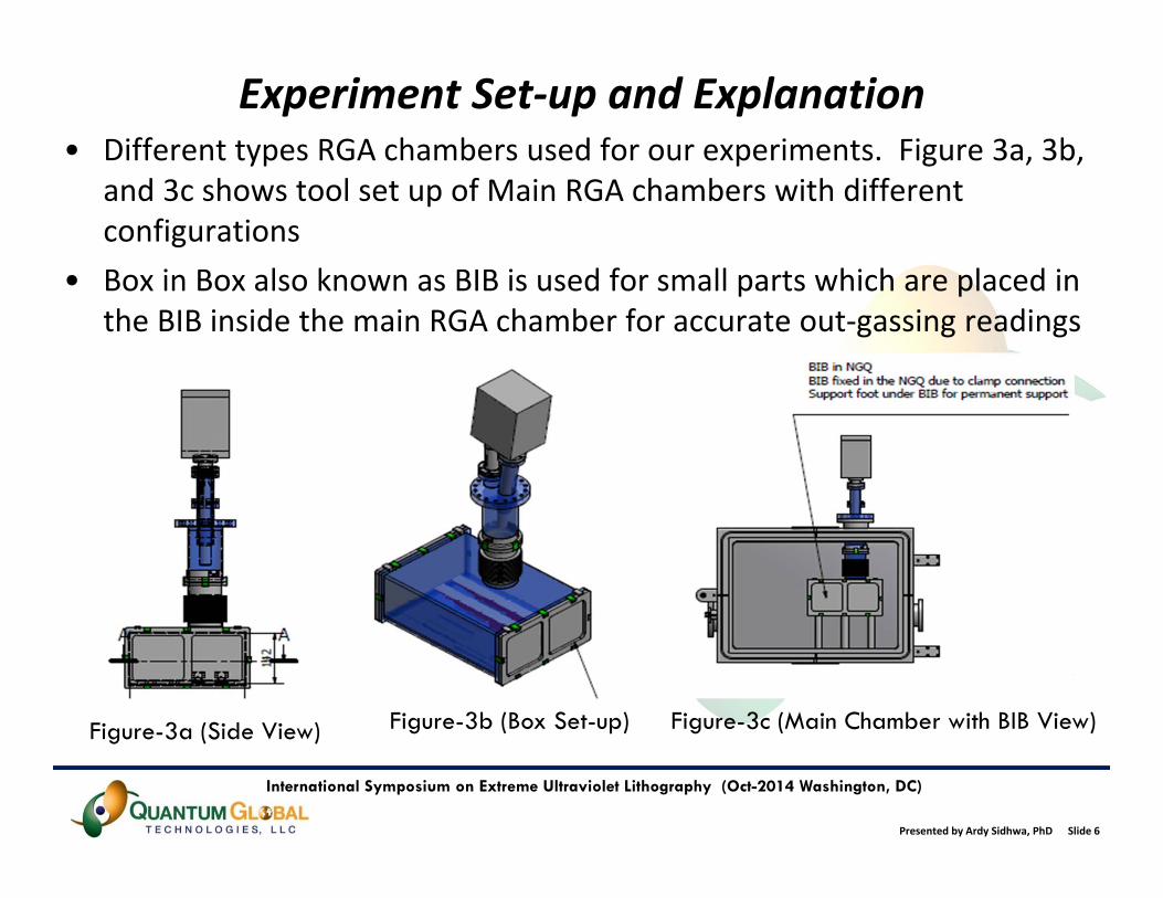
Experiment Set‐up and Explanation• Different types RGA chambers used for our experiments. Figure 3a, 3b,
and 3c shows tool set up of Main RGA chambers with different configurations
• Box in Box also known as BIB is used for small parts which are placed in the BIB inside the main RGA chamber for accurate out‐gassing readings
Figure-3a (Side View) Figure-3b (Box Set-up) Figure-3c (Main Chamber with BIB View)

Presented by Ardy Sidhwa, PhD Slide 7
International Symposium on Extreme Ultraviolet Lithography (Oct-2014 Washington, DC)
RGA Set‐up and Explanation• Parts placement:
• For experiment purposes, parts placement is critical and there should be minimal contact with the chamber
• Note: Overloading and poor part placement runs the risk of virtual leak• Importance of Box in Box (BIB) setup:
• The variety of chambers gives flexibility to provide better chamber loading on product depending on size, quantity and substrate. It is important to use the correct chamber for the product based on the RGA values of the parts
• Baseline integrity check and validation:• RGA requires a specified schedule for validation, integration, and background
• Importance of background scans:• A background scan is run to verify that the chamber is within specification prior
to running qualifications.• If the background scan fails, the RGA goes through a thorough clean process to
make sure it reaches base pressure in a timely fashion with proper background levels

Presented by Ardy Sidhwa, PhD Slide 8
International Symposium on Extreme Ultraviolet Lithography (Oct-2014 Washington, DC)
Process Flow/Description• Different types of parts are received by QuantumClean® from Lithography OEM suppliers and sub‐suppliers
• Parts size can vary from few millimeters to a meter in length • QuantumClean® provide two types of services;
• Parts cleaning process followed by RGA scans• RGA scans only (Parts already cleaned by 3rd party suppliers)
• Figure 4a and 4b depicts Clean‐1 and Clean‐2 processes used by QuantumClean® to clean the suppliers parts prior to RGA scans
• Clean‐1 is used for stringent cleaning which helps to remove organics and inorganic materials from the surface of the part
• Clean‐2 is used for parts that needs the removal of Hydrocarbon elements
• QuantumClean® cleans and scans a diverse selection of Lithography OEM parts with varying substrate, geometry and complexity, using both Clean ‐1 and Clean ‐ 2 cleans. Figure 5 depicts different parts

Presented by Ardy Sidhwa, PhD Slide 9
International Symposium on Extreme Ultraviolet Lithography (Oct-2014 Washington, DC)
Basic Process Flow Example Parts
Clean‐2 and Test Process Flow
Clean‐1 and test Process Flow
Figure 4a
Figure 4b
100mm in Size
200mm in Size
300mm in Size
Presented by Ardy Sidhwa, PhD Slide 10
International Symposium on Extreme Ultraviolet Lithography (Oct-2014 Washington, DC)
Results and Discussions (Cont’d)Challenges faced during the entire process
• Incoming parts from Lithography OEM part suppliers come with high AMU elements ranging from 1 to 200 which will not allow the RGA to get to the base pressure. • Example: Parts with Heli‐coils
• It is important to understand all the failing AMU elements • Due to QuantumClean’s technical capability and capacity, we
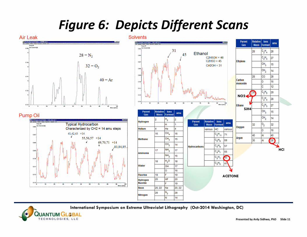
identify the majority of failures associated with respect to parts• Figure‐6 depicts different scans that identifies different elements
out‐gassed during the RGA scan process• However, if the parts are processed in a batch, it becomes
difficult to identify a part causing the high failures
Presented by Ardy Sidhwa, PhD Slide 11
International Symposium on Extreme Ultraviolet Lithography (Oct-2014 Washington, DC)
Figure 6: Depicts Different Scans
HCl
NO2
SiH4
ACETONE

Presented by Ardy Sidhwa, PhD Slide 12
International Symposium on Extreme Ultraviolet Lithography (Oct-2014 Washington, DC)
Results and Discussions (Cont’d)Challenges faced during the entire process
• QuantumClean® would rework the parts if they are cleaned by us and only ship parts that are clean and have passed the RGA requirements
• Note: QuantumClean® only ships 100% passing parts to customers• The QuantumClean® first time yield is >95% on clean and scan product for the past 4‐years, however the failures are reworked in house to achieve 100% conformance
• Parts for RGA scan only will go to the customer with the failing report if the scan fails • RGA scan only test passes 75% on average over 4 years
• QuantumClean® has no control on the incoming part cleanliness• The challenge QuantumClean® faces is what's incoming on the
parts, since no C of A’s are attached to these parts

Presented by Ardy Sidhwa, PhD Slide 13
International Symposium on Extreme Ultraviolet Lithography (Oct-2014 Washington, DC)
Results and Discussions (Cont’d)• Figure 7a shows a part receiving only RGA scan by QuantumClean®
Red = Background ScanBlue = Actual Part Scan
Red = Background ScanBlue = Actual Part Scan

Presented by Ardy Sidhwa, PhD Slide 14
International Symposium on Extreme Ultraviolet Lithography (Oct-2014 Washington, DC)
Results and Discussions (Cont’d)• Figure 7b shows multiple scans for a part cleaned and RGA scanned
by QuantumClean® Red = Background ScanBlue = Actual Part Scan
Red = Background ScanBlue = Actual Part Scan
Presented by Ardy Sidhwa, PhD Slide 15
International Symposium on Extreme Ultraviolet Lithography (Oct-2014 Washington, DC)
Results and Discussions (Cont’d)• Figure 7a shows the table and scan charts for two interval “t1” and “t2”. The “t1”
in the first part of the table depicts 5 hours of background scan followed by “t2,” which depicts another 5 hours of background scan
• The 2nd part of the table shows the data collected from the part/s scanned at “t1” and “t2” intervals. The key elements that are collected in this chart are H2O (moisture), CxHy (volatile), CxHy (non‐volatile) elements.
• It’s clear from Mass Spectrum “t1” and “t2” that this part failed heavily for all the elements including Moisture, Carbon, Boron, Oxygen, Nitrogen, Methanol, CxHy (volatile), CxHy (non‐volatile) and Pump oils elements
• Now imagine this part being installed into a EUV lithography tool. The amount of time, expense, and loss of production time involved in detecting this failing part inside the vacuum chamber is astronomical
• Figure 7b depicts the same part cleaned by QuantumClean® first and then running through the RGA scans. The table and scan data depicts the condition of the part which will pass inside the EUV lithography tool the first time and every time
• The key to the success is the cleaning and baking of the parts by using QuantumClean® proprietary ACS™ cleaning process

Presented by Ardy Sidhwa, PhD Slide 16
International Symposium on Extreme Ultraviolet Lithography (Oct-2014 Washington, DC)
Conclusion and Summary• This paper presents the importance of parts cleaning using the
QuantumClean® ACS™ process for parts used in the Lithography tools mainly EUV tools
• It also places emphasis on the processes used to clean, bake, and analyze the parts prior to installing the parts inside the Lithography vacuum chambers
• Failure to do so can impact the tool performance and integrity along with loss of production time
• QuantumClean® is a preferred cleaning supplier for large Lithography OEM manufacturers
• With QuantumClean® capabilities, we can help all our customers reduce their CoO by providing superior clean parts along with analytical data supporting our cleanliness