supports
TRANSCRIPT

Pipe Supports Modeler Reference Guide Document Number Version Date Pages DPDS3-PB-200026A PDS 7.1 April 2002 1-352 DPDS3-PB-200026B PDS 7.3 October 2004 Cover/Notice DPDS3-PB-200026C PDS 8.0 SE November 2005 Cover/Notice DPDS3-PB-200026D PDS 8.0 SE March 2007 353-362

Copyright Copyright © 1984-2007 Intergraph Corporation. All Rights Reserved.
Including software, file formats, and audiovisual displays; may be used pursuant to applicable software license agreement; contains confidential and proprietary information of Intergraph and/or third parties which is protected by copyright law, trade secret law, and international treaty, and may not be provided or otherwise made available without proper authorization.
Restricted Rights Legend Use, duplication, or disclosure by the government is subject to restrictions as set forth below. For civilian agencies: This was developed at private expense and is “restricted computer software” submitted with restricted rights in accordance with subparagraphs (a) through (d) of the Commercial Computer Software - Restricted Rights clause at 52.227-19 of the Federal Acquisition Regulations (“FAR”) and its successors, and is unpublished and all rights are reserved under the copyright laws of the United States. For units of the Department of Defense (“DoD”): This is “commercial computer software” as defined at DFARS 252.227-7014 and the rights of the Government are as specified at DFARS 227.7202-3.
Unpublished – rights reserved under the copyright laws of the United States.
Intergraph Corporation Huntsville, Alabama 35894-0001
Warranties and Liabilities All warranties given by Intergraph Corporation about equipment or software are set forth in your purchase contract, and nothing stated in, or implied by, this document or its contents shall be considered or deemed a modification or amendment of such warranties. Intergraph believes the information in this publication is accurate as of its publication date.
The information and the software discussed in this document are subject to change without notice and are subject to applicable technical product descriptions. Intergraph Corporation is not responsible for any error that may appear in this document.
The software discussed in this document is furnished under a license and may be used or copied only in accordance with the terms of this license.
No responsibility is assumed by Intergraph for the use or reliability of software on equipment that is not supplied by Intergraph or its affiliated companies. THE USER OF THE SOFTWARE IS EXPECTED TO MAKE THE FINAL EVALUATION AS TO THE USEFULNESS OF THE SOFTWARE IN HIS OWN ENVIRONMENT.
Trademarks Intergraph, the Intergraph logo, PDS, SmartPlant, SmartSketch, FrameWorks, INtools, MARIAN, ISOGEN, and IntelliShip are registered trademarks and SupportModeler and SupportManager are trademarks of Intergraph Corporation. Microsoft and Windows are registered trademarks of Microsoft Corporation. MicroStation is a registered trademark of Bentley Systems, Inc. Other brands and product names are trademarks of their respective owners.

If You Need Assistance________________
If You Need Assistance
Intergraph Online
Our web site brings you fast, convenient, up-to-the-minute information about Intergraph’sproducts, services, and direction. Our web address is: http://www.intergraph.com.
Support
For the lasest Support Services information, use a World Wide Web browser to connect tohttp://www.intergraph.com/ppo/services/support.asp.
If you are outside of the United States, please call your local Intergraph office. The most up-to-date list of international offices and distributors is available on the web athttp://www.intergraph.com.
Intergraph Directory
The following numbers are only valid in the United States unless otherwise indicated. If youare outside the United States, please call your local Intergraph office.
Intergraph General Information
All countries — 1-256-730-2000
Training Registration
1-800-766-7701 (U.S. Only)
1-256-730-5400 (Outside the U.S.)
Mailing Address
Intergraph Process, Power & Offshore300 Intergraph WayMadison, Alabama 35758U.S.A.
You can also reach us by electronic mail at [email protected].
3

________________
Documentation Contacts
We are constantly working on updates and improvements to the documents and othereducational media. If you have any suggestions on where we can improve the documentationor where you think more information is needed, let us know. You can reach us by:
Mail Intergraph Process, Power & OffshoreDocumentation Manager300 Intergraph WayMadison, AL 35758
4

Table of Contents________________
Table of Contents
If You Need Assistance ........................................................................................................ 3Intergraph Directory ............................................................................................................. 3
Preface .......................................................................................................................................... 9
Document Purpose ................................................................................................................ 9Document Prerequisites / Audience ...................................................................................... 9Related Documents/Products ................................................................................................ 9About this Document ............................................................................................................ 10Additional Information ......................................................................................................... 10
General Conventions .................................................................................................................... 11
Keyboard Conventions ......................................................................................................... 12Terminology ......................................................................................................................... 13
1. PDS Pipe Support Module ........................................................................................................... 15
1.1 PDS Pipe Supports Features ............................................................................................... 161.2 Pipe Support Specifics ........................................................................................................ 171.3 Pipe Supports Data Flow ..................................................................................................... 181.4 Pipe Support Setup Checklist .............................................................................................. 19
2. Pipe Support Reference Data ....................................................................................................... 21
2.1 Pipe Support Group Reference Data ................................................................................... 22
2.1.1 Pipe Support Group Data Table 240 ....................................................................... 232.1.2 Pipe Support Commodity Reference Data Table 241 ............................................. 24
2.2 Pipe Support Material Reference and Description Data ..................................................... 26
2.2.1 Pipe Support Material Reference Data Table 242 ................................................... 272.2.2 Pipe Support Material Description Data Table 243 ................................................ 30
2.3 Support User-Interface Definition Form and Table ............................................................ 33
3. Pipe Supports Modeler ................................................................................................................. 35
3.1 Supports Commands ........................................................................................................... 36
3.1.1 Pipe Support Place Commands ............................................................................... 373.1.2 PPSM Place Supports .............................................................................................. 38
5

Pipe Supports Modeler Reference Guide — April 2002________________
3.1.2.1 Point In Space .......................................................................................... 413.1.2.2 Point on Pipe ............................................................................................ 42
3.1.3 Delivered Pipe Supports .......................................................................................... 433.1.4 Copy Pipe Support .................................................................................................. 503.1.5 Physical Pipe Support ............................................................................................. 53
3.2 Place Logical Support ......................................................................................................... 553.3 Revise Pipe Support Commands ......................................................................................... 57
3.3.1 Revise Attributes ..................................................................................................... 583.3.2 Support Group ......................................................................................................... 603.3.3 Support Gang .......................................................................................................... 633.3.4 Move Pipe Support .................................................................................................. 663.3.5 Delete Pipe Support ................................................................................................. 68
3.4 Review Data Commands ..................................................................................................... 69
3.4.1 Review Attributes .................................................................................................... 703.4.2 Review Nozzle Data ................................................................................................ 723.4.3 Review Report ......................................................................................................... 733.4.4 Temporary Symbology ............................................................................................ 76
3.4.4.1 Active Color ............................................................................................. 783.4.4.2 Active Weight .......................................................................................... 793.4.4.3 Active Line Style ...................................................................................... 803.4.4.4 Display Only Labels ................................................................................. 813.4.4.5 Restore Permanent Symbology ................................................................ 82
3.5 Analyze Data Commands .................................................................................................... 83
3.5.1 Design Review ........................................................................................................ 843.5.2 Piping Clash Review ............................................................................................... 873.5.3 Piping Clash Check ................................................................................................. 903.5.4 Design Check Review ............................................................................................. 923.5.5 Review RDB Report ............................................................................................... 93
3.6 View Commands ................................................................................................................. 963.7 File Commands ................................................................................................................... 97
3.7.1 File Options ............................................................................................................. 98
3.7.1.1 Return to Piping ....................................................................................... 983.7.1.2 Switch to FWP ......................................................................................... 98
3.8 Element Commands ............................................................................................................ 1003.9 Settings Command .............................................................................................................. 1013.10 User Commands ................................................................................................................ 1023.11 Applications Command ..................................................................................................... 103
6

Table of Contents________________ 4. Pipe Support Explorer .................................................................................................................. 105
4.1 Pipe Supports Modeler ........................................................................................................ 1074.2 Reference Viewer ................................................................................................................ 1084.3 Support/Drawing Report ..................................................................................................... 1094.4 Print Document ................................................................................................................... 1104.5 Show Drawings ................................................................................................................... 1114.6 Delete Drawing ................................................................................................................... 1124.7 Show Supports .................................................................................................................... 1134.8 Properties ............................................................................................................................. 1144.9 View Drawing ..................................................................................................................... 1154.10 Generate Drawing ............................................................................................................. 1164.11 Large Icon View ................................................................................................................ 1174.12 Small Icon View ................................................................................................................ 1184.13 List View ........................................................................................................................... 1194.14 Details View ...................................................................................................................... 1204.15 Help ................................................................................................................................... 1214.16 Exit .................................................................................................................................... 122
5. SmartSketch Symbol Introduction ............................................................................................... 123
5.1 Drawing Automation ........................................................................................................... 125
5.1.1 PPSM Symbols ....................................................................................................... 1275.1.2 Standard Support Graphic Symbols ........................................................................ 1285.1.3 Drawing Layout Symbols ....................................................................................... 1295.1.4 Drawing Title Block (dwgTitleBLock.sym) ........................................................... 1305.1.5 Support Drawing Formatted Text ........................................................................... 1315.1.6 Support Location Key Plan ..................................................................................... 1325.1.7 Drawing Layout Customization .............................................................................. 133
5.2 Creating Drawing Seed Files .............................................................................................. 1355.3 Create A SmartSketch Drawing .......................................................................................... 1365.4 Create A Symbol ................................................................................................................. 1375.5 Edit A Symbol ..................................................................................................................... 1385.6 Edit Symbol Properties ....................................................................................................... 1405.7 Manipulate A Symbol ......................................................................................................... 1415.8 Open A Symbols Library .................................................................................................... 1425.9 Place A Symbol ................................................................................................................... 143
Appendix A: Drawings .................................................................................................................... 145
A.1 AXIAL STOP-WELDED (AW) ............................................................................................... 146A.2 CANTILEVER-BRACED (CB) ............................................................................................... 150A.3 CANTILEVER-CANTILEVER (CC) ...................................................................................... 155A.4 DUMMY LEG-HORIZONTAL (DH) ...................................................................................... 159A.5 DUMMY LEG-HORIZONTAL (DH) ...................................................................................... 166A.6 DUMMY LEG-VERTICAL (DV) ............................................................................................ 171A.7 DUMMY LEG-VERTICAL (DV) ............................................................................................ 176A.8 DUMMY LEG-VERTICAL (DV) ............................................................................................ 180
7
Pipe Supports Modeler Reference Guide — April 2002________________ A.9 DUMMY LEG-VERTICAL (DV) ............................................................................................ 183A.10 FRAMES - FLANGED (FF) ................................................................................................... 187A.11 FRAMES-L SHAPE (FL) ....................................................................................................... 192A.12 GUIDE (GG) ........................................................................................................................... 197A.13 GUIDE (GG) ........................................................................................................................... 202A.14 GUIDE-HOLD DOWN (GH) ................................................................................................. 205A.15 ROD HANGER (RH) .............................................................................................................. 209A.16 SHOE CLAMPED (SC) .......................................................................................................... 215A.17 SHOE WELDED (SW) ........................................................................................................... 219A.18 VESSEL-GUIDE (VG) ........................................................................................................... 223A.19 VESSEL-GUIDE (VG) ........................................................................................................... 225A.20 VESSEL-SUPPORT (VS) ...................................................................................................... 227A.21 VESSEL-SUPPORT (VS) ...................................................................................................... 230A.22 VESSEL-SUPPORT (VS) ...................................................................................................... 232A.23 VARIABLE SPRING HANGER (XV) .................................................................................. 234
Appendix B: Moment Calculations .................................................................................................. 241
Appendix C: Delivered Pipe Support Forms and Tutorial Definition Files ..................................... 259
Cantilever - Braced (CBA) .................................................................................................. 260Cantilever - Cantilever (CC) ............................................................................................... 261Dummy Leg - Horizontal (DH) ........................................................................................... 262Dummy Leg - Vertical (DV) ............................................................................................... 263Frames Flange (FF) ............................................................................................................. 264Frames L-Type (FL) ............................................................................................................ 265Guide - Guide (GG) ............................................................................................................ 266Guide - Hold Down (GH) ................................................................................................... 267Rod - Hanger (RH) .............................................................................................................. 268Shoe - Clamped (SC) .......................................................................................................... 269Shoe - Welded (SW) ........................................................................................................... 270Vessel - Guide (VG) ............................................................................................................ 271Vessel - Support (VS) ......................................................................................................... 272Variable Spring Hanger (XV) ............................................................................................. 273
Appendix D: Delivered Pipe Support Symbols ............................................................................... 275
Glossary ............................................................................................................................................... 341
Index .................................................................................................................................................... 349
8

Table of Contents________________
Preface
Document Purpose
This document is a reference guide for the Pipe Supports Modeler module of the PDS 3D products. PDS 3Duses interactive graphics and database management techniques to integrate the engineering and design/draftingexecution of plant design.
The Pipe Supports Modeler module is one part of the overall Plant Design System. It is specifically designed toprovide recording Pipe Support Reference Data, Pipe Support 3D Graphic Modeling and Pipe Support DrawingProduction capabilities.
Document Prerequisites / Audience
This document is intended for piping designers who have a working knowledge of Piping Design Graphics(PD_Design).
Related Documents/Products
MicroStation software is required to operate the PDS 3D Modules. Information about MicroStationcapabilities can be found in the following documents:
MicroStation Reference Guide
MicroStation User’s Guide
Intergraph Corporation’s Relational Interface System (RIS)TM is required to operate PDS 3D, along with arelational database management system (RDBMS) supported by RIS. Currently, these include Informix,Oracle, and Ingres. Information about RIS capabilities can be found in the following documents:
Relational Interface System (RIS) Reference Manual
Relational Interface System (RIS) Operator Training Guide
For more information on related aspects of the PDS 3D products, consult the following documents:
PDS Reference Data Manager (PD_Data) Reference Guide
PDS Piping Design Graphics (PD_Design) Reference Guide
PDS Equipment Modeling (PD_Eqp) Reference Guide
PDS Report Manager (PD_Report) Reference Guide
9
Pipe Supports Modeler Reference Guide — April 2002________________
About this Document
This document contains front matter, numbered sections, appendices, a glossary, and an index. Much of thisdocument is devoted to a description of the forms used to setup and maintain a project.
Section 1 Provides an overview of the Pipe Supports Module. It describes general information, terms,and work flow.
Section 2 Provides information related to the Pipe Supports Reference Data.
Section 3 Provides information related to the Pipe Supports Modeler features and commands.
Section 4 Provides information related to the Pipe Support Explorer features and commands.
Section 5 Provides information related to the SmartSketch symbols used in the Pipe Supports Module.
Appendices Provide Pipe Support Drawings, Moment Calculations, Forms, Tutorial Definition Files,and Symbols.
Additional Information
The following informational files are delivered with the Pipe Supports Modeler software in thewin32app\ingr\pdshell directory.
File Name Contents
README Describes changes and additions to the product since the last version. For a fixes release, thefixes are appended to the top of the initial file to provide a history of all changes to theproduct. Includes Comments and Trouble Report numbers which describe what problemshave been fixed. Provides special notices to the customer. Lists any exceptions made to thecertification.
10

Table of Contents________________
General Conventions
This document contains many visual cues to help you understand the meaning of certainwords or phrases. The use of different fonts for different types of information allows you toscan the document for key concepts or commands. Symbols help abbreviate and identifycommonly used words, phrases, or groups of related information.
Typefaces
Italic Indicates a system response, which is an explanation of what the software isdoing. For example,
The text is placed in the viewing plane.
Bold Indicates a command name, parameter name, or dialog box title. Commandpaths are shown using an arrow between command names. For example,
Choose File > Open to load a new file.
Sans serif Indicates a system prompt or message, which requires an action be taken bythe user. For example,
Select first segment of alignment
Bold TypewriterIndicates what you should literally type in. For example,
Key in original.dat to load the ASCII file.
Normal TypewriterIndicates an actual file or directory name. For example,
The ASCII report is stored in the layout.rpt file.
11
Pipe Supports Modeler Reference Guide — April 2002________________
Symbols
This document uses the following symbols to represent mouse buttons and to identify specialinformation:
<C> Command button<D> Data button (usually the left mouse button)<R> Reset/reject button (usually the right mouse button)<T> Tentative button (usually the center mouse button)
Note — Important supplemental information.
Warning — Critical information that could cause the loss of data if not followed.
Technical tip or information — provides information on what the software isdoing or how it processes information.
Map or path — shows you how to get to a specific command or form.
More information — indicates there is additional or related information.
Need a hint — used with activities and labs, provides a tip or hint for doing theexercises.
Keyboard Conventions
The following list outlines the abbreviations this document uses for keyboard keys anddescribes how to use them in combination. You can make some menu selections through theuse of keyboard accelerators, which map menu selections to key combinations.
ALT Alternate keyCTRL Control keyDEL Delete keyENTER Enter keyESC Escape key
CTRL+z To hold down the Control key and press Z.ESC,k To press the Escape key, then K.
12
Table of Contents________________
Terminology
Click To use a mouse or key combination to pick an item that begins anaction. For example,
Click Apply to save the changes.
Select To mark an item by highlighting it with key combinations or by pickingit with your cursor. Selecting does not initiate an action. Afterselecting an item, you click the action you want to affect the item. Forexample,
Select the file original.dat from the list box, then click Delete toremove it from the directory.
In addition, you would select items to define parameters, such asselecting toggle buttons. This also applies to selecting graphicelements from the design file. For example,
Select the line string to define the graphic template.
Tentative-select To place a tentative point on an existing graphic element in a designfile. If you are using the CLIX operating system, you tentative-selectby double-clicking with a mouse or pressing <T> on a hand-heldcursor. If you are using the Windows NT operating system, youtentative-select by pressing a left-button, right-button chord.
Double-click To select and execute a command by clicking the mouse or hand-heldcursor button twice in rapid succession. This term implies that you areclicking the data button (<D>) as part of a menu or dialog box action.For example,
Double-click on the file original.dat to load it into the new surface.
Drag To press and hold the data button (<D>) while moving the mouse orhand-held cursor.
Type To key a character string into a text box.
Key in To type in data and press ENTER to enter the data and execute thedefault action.
In a dialog box, pressing TAB after keying in data willenter the data and move the cursor to the next field.
13

Pipe Supports Modeler Reference Guide — April 2002________________
14

1. Overview
PDS Pipe Support Module________________
1. PDS Pipe Support Module
This document describes a generic approach for the placement of pipe supports. This generic approach allowsflexibility in the definitions of the pipe support standard as well as the vendor pipe support component. Thesedefinitions are completely user-definable, and thus can be used for different standard practices of variousindustries.
The PDS Pipe Support Module enhancements include the following areas:
Pipe Support Reference Data — The PDS Reference Data Manager software and Piping JobSpecification/RDB data provides functionality for Standard Support RDB definition. This support RDBdata is used to provide the user with the "spec-driven" Pipe Support design and modeling capability.
Pipe Support 3D Graphic Modeling — The PDS_Design graphic command environment and Edenparametric feature within 3D piping allows modeling of the pre-defined standard support and the supportsupplemental steel using Pipe Support Reference Data.
Pipe Support Drawing Production — User definable Pipe Support Drawings are automaticallyproduced using pre-defined pipe support graphic symbols. The Support Drawing module is stand-alonesoftware using Intergraph’s object-based, Microsoft Office compliant SmartSketch technology.
15
Pipe Supports Modeler Reference Guide — April 2002________________
1.1 PDS Pipe Supports Features
Specification-assisted data handling.
Standard steel sections available for modeling based on AISC and other Standards,
Ability to switch to Support Modeler from Piping Design to model pipe supports while routing pipe.
Automatic calculation of cut lengths and sizes.
Automatic bill of materials reporting.
Automatic construction drawing generation (with Intergraph’s SmartSketch product).
Key Plan Symbol generation to locate your support with respect to the structural grid.
Access to EDEN Application Program Interface (API) to model your company’s standard supportsparametrically. Include the new standard supports in a library for reuse.
Ability to customize your pipe support forms.
Ability to Group/Gang your supports to model special supports.
Interference checking against all your 3D plant model items.
Inclusion in 3D plant design visualizations and orthographic drawings.
16
1. Overview
Pipe Support Specifics________________
1.2 Pipe Support Specifics
The Pipe Support Module contains the following functionality:
Support Component — An individual part. This is the industry-standard support component, alsoreferred to as the off-the-shelf component from the vendor catalog. (i.e., rod, clamp, spring, shoe.)
Standard Support — A user-defined grouping of one or more support components with the designbased on standard configurations. The detailed dimensions and part sizes vary based on vendor catalogand piping parameters in the 3D model. (i.e., Rod-Hangers, Spring Support Assembly)
Group Assembly — A grouping of two or more support standards or components that support a givenpipe location. The groupings enable the system to create drawings or reports for the Group Assembly as asingle support system.
Ganged Assembly — A grouping of two or more support standards or components that support severalpipes. The Ganged Assembly always has one principle support as the parent support of the assembly, andthe rest of supports are treated as the child component of the principle support item.
Support User-Interface Definition Table — A user-defined form interface to Eden which allows thePDS Pipe Support Module to collect input via keying fields or command selections on the form.
17
Pipe Supports Modeler Reference Guide — April 2002________________
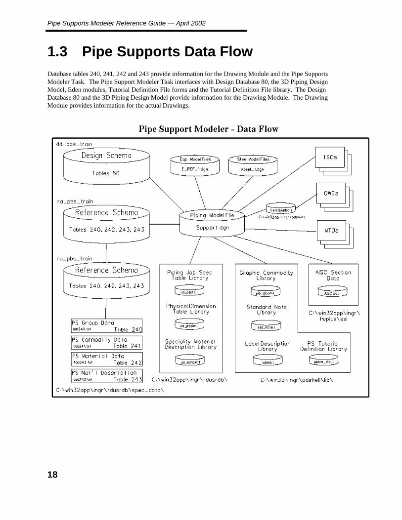
1.3 Pipe Supports Data Flow
Database tables 240, 241, 242 and 243 provide information for the Drawing Module and the Pipe SupportsModeler Task. The Pipe Support Modeler Task interfaces with Design Database 80, the 3D Piping DesignModel, Eden modules, Tutorial Definition File forms and the Tutorial Definition File library. The DesignDatabase 80 and the 3D Piping Design Model provide information for the Drawing Module. The DrawingModule provides information for the actual Drawings.
18

1. Overview
Pipe Support Setup Checklist________________
1.4 Pipe Support Setup Checklist
Project Configuration for Pipe Supports
1. Use the Reference Data Manager, Piping Job Specification Manager to load the following neutralfiles:
Pipe Support Group Data tab240.txtPipe Support Commodity Data tab241.txtPipe Support Material Data tab242.txtPipe Support Material Description tab243.txt
These files are delivered in the rdusrdb\spec_data directory. Post Unapproved to Approved whencomplete.
2. Use the Reference Database Management Data to set the locations for the following libraries:
Pipe Support Section Table Library fileserver projdir\rdb\lib\approved AISC fileserverprojdir\rdb\lib\unapproved AISC Copy AISC.DAT and AISC.IDX from the fwplus\es1 directory into theapproved and unapproved directories.
User Section Library is not supported.
Pipe Support Tutorial Definition Library fileserver projdir\rdb\lib\approved ppsm_tlib.1 fileserverprojdir\rdb\lib\unapproved ppsm_tlib.1 The ppsm_tlib.1 library is delivered in the pdshell\lib directory.
Pipe Support Seed Files fileserver projdir\dwg\PsmSymbols (no file spec) fileserverprojdir\dwg\PsmSymbols (no file spec) Create the PSmSymbols directory under the dwg directory. Thencopy the contents of the pdshell\PsmSymbols directory into this location.
Pipe Support Drawings Base Directory fileserver projdir\dwg\psm fileserver projdir\dwg\psm Thisdirectory will initially be empty.
3. Once all settings have been initialized, the Pipe Supports module may be started.
19

Pipe Supports Modeler Reference Guide — April 2002________________
20
2. Pip
e Su
pp
orts
Referen
ce Data
Pipe Support Reference Data________________
2. Pipe Support Reference Data
The Pipe Support Module is a specification-driven task. The Material/Specification Reference Database isaccessed during the placement of each component. The system reads the specification, retrieves the datarequired to access the Graphic Commodity Library and Physical Data Library, and completely define the pipesupport.
A set of standards provides commonly used support configurations. These standard specifications handle mostof the pipe support designs for a project. Exceptions can be designed manually. The delivered data can becustomized for any project specific requirements.
PDS delivered specifications, EDEN code and forms for some of the most commonly used pipe supports whichincorporate:
Commercial support catalog components.
Standard steel sections (AISC and other standards).
Design rules for sizing, temperature, and compatibility can be built in to EDEN.
Built-in checks for override and illogical placement.
The Material/Specification Reference Database contains a set of tables used to define specification and materialdata for Pipe Supports. These tables contain information necessary for the implementation of the PPSM UserCustomizable Interface capability, Pipe Support modeling task, MTO reporting and Drawing productionenhancements.
Pipe Support Group Data Table 240, page 23 Pipe Support Group Data (240)
Pipe Support Commodity Reference Data Table 241, page 24 Pipe Support Commodity Reference Data(241)
Pipe Support Material Reference Data Table 242, page 27 Pipe Support Material Reference Data (242)
Pipe Support Material Description Data Table 243, page 30 Pipe Support Material Description Data(243)
Reference Data and 243 Pipe Support Material Description Data are contained in the PDS Piping JobSpecification (PJS). These tables contain information necessary for the implementation of the PPSM UserCustomizable Interface capability, Pipe Support modeling task, MTO reporting and Drawing productionenhancements.
Refer to the Reference Data Manager Reference Guide for a detailed description of the Pipe Support JobSpecification and Graphic Commodity Library. Refer to the PDS EDEN Interface Reference Guide forinformation on adding new symbols to the Graphic Commodity Library.
21

Pipe Supports Modeler Reference Guide — April 2002________________
2.1 Pipe Support Group Reference Data
Table 240 is used to establish the user-definable pipe support family within the PDS project environment. Thislist is used for selection, and provides filtering for table 241 pipe support commodity data selection. Forexample, the user’s selection of AW, the Axial Stop-Welded support group, results in a list of the availablesupport commodities for selection based on the pipe size and the support group.
22

2. Pip
e Su
pp
orts
Referen
ce Data
Pipe Support Group Data Table 240________________
2.1.1 Pipe Support Group Data Table 240
The Pipe Support Group Data Table contains 3 attributes:
1. system_unique_no (integer)
2. support_group (character*6) This attribute defines the generic pipe support group name used in Table241 to filter the selection of the pipe support commodities. This field must contain a unique identifier.This generic field name can be a corporate pipe support standard group name, or an individual supportcomponent name.
3. support_group_description (character*40) This attribute is the description of the support group. Thisfield is presented to the user during the pipe support model command.
Neutral File Format
The following is a sample neutral file for the Pipe Support Group Data Table 240. Entries in this table shouldbe sorted alphanumerically by Support Group.
! PIPE SUPPORT GROUP REFERENCE DATA! Wed Feb 25 09:12:22 1998
! 2=support_group! 3=group_descr
Double_SpacingSequence= 2 3
! 2 3
AW AXIAL STOP - WELDED (AW)CB CANTILEVER - BRACE (CB)CC CANTILEVER - CANTILEVER (CC)DH DUMMY LEG - HORIZONTAL (DH)DV DUMMY LEG - VERTICAL (DV)FL FRAMES L-TYPE (FL)GG GUIDE - GUIDE (GG)GH GUIDE - HOLD DOWN (GH)VG VESSEL - GUIDE (VG)VS VESSEL - SUPPORT (VS)RH ROD - HANGER (RH)SC SHOE - CLAMPED (SC)SW SHOE - WELDED (SW)PTHARD PTP HARDWARE
Sample Files
A sample neutral file for US practice is delivered in the file win32app\ingr\rdusrdb\spec_data\tab240.txt.
23

Pipe Supports Modeler Reference Guide — April 2002________________
2.1.2 Pipe Support Commodity Reference DataTable 241
Table 241 contains the pipe support standard or the vendor catalog components data set required within the PDSproject. This table works in conjunction with table 242, 243 Pipe Support Material Reference/Description Dataand provides the connection to the pipe support user-interface definition library.
The Pipe Support Commodity Reference Data Table contains 11 attributes:
1. system_unique_no (integer)
2. support_group (character*6) This attribute defines the generic pipe support group name.
3. support_commodity_name (character*6) This attribute identifies the pipe support commodity itemname. This attribute is the key to table 242 Pipe Support Material Reference Data. This field can be astandard support item or an individual support.
4. from_nom_diam (short (NPD Units))
5. to_nom_diam (short (NPD Units)) These coded attributed identify the range of the nominal pipingdiameter of the pipe to be supported (lower bound to higher bound) in NPD Units. The to value mustequal or exceed the from value.
6. tdf_table_name (Character*8) This attribute contains the name of the pipe support TDF table. Thisattribute is used to display placement design data to the user about the selected pipe support standard andallowing for input of data by the user.
7. temperature (character*8) This attribute contains the pipe support standard temperature limit.
8. schedule_table (character*8) This attribute contains the schedule table name of the support standard.(Not functional)
9. attachment_type (short) This attribute contains the code value that specifies the structure attachment ofsupport. The value of 0 indicates that support does not require any structural attachment, for supportitems with code value of 1.
10. model_code (character*6) This attribute contains the Eden module symbol name. The same model codecan be assigned to different support commodity items.
11. description_of_commodity (character*50) This attribute contains the description of the pipe supportcommodity to help with the selection process.
Neutral File Format
The following is a sample neutral file for the Pipe Support Commodity Data Table.
! PIPE SUPPORT MATERIAL REFERENCE DATA! Wed Feb 25 09:18:21 1998
24

2. Pip
e Su
pp
orts
Referen
ce Data
Pipe Support Commodity Reference Data Table 241________________ ! 2=commodity_name! 3=npd_from! 4=npd_to! 5=geometric_standard! 6=material_index! 7=drawing_seed! 8=item_key0! 9=item_key1! 10=item_key2
Single_SpacingSequence= 2 3 4 5 6 7 8 9 10
! 2 3 4 5 6 7 8 9 10
AWA 1.0" 3.0" - AWA01 AWA 1 - -AWB 4.0" 8.0" - AWB01 AWB 1 - -AWC 10.0" 14.0" - AWC01 AWC 1 - -AWC 16.0" 24.0" - AWC02 AWC 2 - -AWC 26.0" 36.0" - AWC03 AWC 3 - -AWD 2.0" 8.0" - AWD01 AWD 1 - -AWE 10.0" 22.0" - AWE01 AWE 2 - -AWE 24.0" 36.0" - AWE02 AWE 3 - -AWF 1.0" 3.0" - AWF01 AWF 1 - -AWF 4.0" 6.0" - AWF02 AWF 2 - -AWF 8.0" 10.0" - AWF03 AWF 3 - -AWF 12.0" 14.0" - AWF04 AWF 4 - -AWF 16.0" 24.0" - AWF05 AWF 5 - -CBA - - - CBA01 CBA 1 - -CBA - - - CBA02 CBA 2 - -CBA - - - CBA03 CBA 3 - -CBA - - - CBA04 CBA 4 - -CBA - - - CBA05 CBA 5 - -CBB - - - CBB01 CBB 1 - -CBB - - - CBB02 CBB 2 - -CCA - - - CCA01 CCA 1 - -CCA - - - CCA02 CCA 2 - -CCA - - - CCA03 CCA 3 - -CCA - - - CCA04 CCA 4 - -CCA - - - CCA05 CCA 5 - -CCA - - - CCA06 CCA 6 - -CCA - - - CCA07 CCA 7 - -CCA - - - CCA08 CCA 8 - -CCA - - - CCA09 CCA 9 - -CCA - - - CCA10 CCA 10 - -CCB - - - CCB01 CCB 1 - -CCB - - - CCB02 CCB 2 - -CCB - - - CCB03 CCB 3 - -CCB - - - CCB04 CCB 4 - -CCB - - - CCB05 CCB 5 - -CCB - - - CCB09 CCB 9 - -CCB - - - CCB10 CCB 10 - -PT50 0.5" 36" 4190 PT50 PT50 - - -PT60 3.0" 36" 4190 PT60 PT60 - - -PT70 0.5" 36" 4190 PT70 PT70 - - -PT80 1.5" 36" 4190 PT80 PT80 - - -PT100 0.5" 36" 4190 PT100 PT100 - - -
Sample Files
A sample neutral file for US practice is delivered in the file win32app\ingr\rdusrdb\spec_data\tab241.txt.
25
Pipe Supports Modeler Reference Guide — April 2002________________
2.2 Pipe Support Material Reference andDescription Data
The support material reference and description data is used for the following purposes:
Eden module graphic placement/support sub-component name lookup.
Support detail drawing MTO data.
Pipe support material takeoff reports.
The detailed material description of support commodity items varies depending on the support’s specific designparameters. These parameters include the NPD of pipe being support and other specific support item identifiersdetermined by the support’s design and placement requirements, such as the specific Cantilever support ItemTypes that derived from the load data, and various Rod Hanger’s beam attachment and pipe attachmentrequirements. A given support commodity item with different design parameters will have significantlydifferent material description MTO data.
After the successful placement of support, the Support design database entry for the placed support shouldcontain the access key value in attributes 43 material_index of table 80. The PPSM drawing module uses thismaterial access key value from design database data to retrieve pertinent MTO data for support item from table243 (Material Description Data).
26

2. Pip
e Su
pp
orts
Referen
ce Data
Pipe Support Material Reference Data Table 242________________
2.2.1 Pipe Support Material Reference Data Table242
The Pipe Support Material Reference Data Table 242 (Support Material Reference) provides table lookupmechanism using support commodity name and design parameters to retrieve the material_index for supportcommodity item with specific design parameters. The table 243 (Support Material Description Data) containsdetailed material description of specific pipe support. The material_index attribute is the linked access keybetween table 242, 243 and design table 80 for a given support commodity item with specific designparameters.
Table 242 contains material reference data of support item that have specific design parameters. Thecommodity_name, item_from_npd, item_to_npd, and item_key0-3 attributes are the access keys for retrieval ofthe material index value. These attributes can be used as table lookups for picking up material_index by Load_Spec_Data() function in Eden.
User can use either diameter range (item_from_ndp-item_to_ndp ) or item_key0, item key1, anditem_key2 as lookup for picking up material_index. Both diameter range and item_keys cannotbe used for lookup at the same time.
The Pipe Support Material Reference Data Table contains 10 attributes:
1. system_unique_no (integer)
2. commodity_name (character*6) This attribute matches the attribute 3 of reference database table 241and design database table 80. Attribute 3 in table 241 is primary index into this database table. Thisattribute is the access key required for the support material index table lookup.
3. item_from_npd (short) This attribute is for those pipe support commodities which have an NPDrequirement. This value is the minimum nominal piping diameter. If this value is NPD in English units,it must be coded for it to be interpreted correctly. This attribute is the access key required for the supportmaterial index data table lookup. The value of zero denotes the key is not being used.
4. item_to_npd (short) This attribute is for those pipe support commodities which have an NPDrequirement, this value is the maximum nominal piping diameter.If this value is NPD English units, it must be coded for it to be interpreted correctly. This attribute is theaccess key required for the support material index data table lookup. The value of zero denotes the key isnot being used.
These attributes are the design parameters access key values for the support material index data tablelookup. The value of NULL denotes the key is not being used.
5. geo_std_index = CL575
6. material_index (character 16) This attribute is the linked access key between table 242, 243 and designtable 80 for a support commodity item with specific design parameters. The value of this attribute isunique in table 242. This attribute matches the attribute 44 from design database table 80.
7. drawing_seed (character 16) This attribute contains the graphic seed file name for support commodityitem with specific design parameters.
27
Pipe Supports Modeler Reference Guide — April 2002________________
8. item_key0 (character 2)
9. item_key1 (character 2)
10. item_key2 (character 2)
Neutral File Format
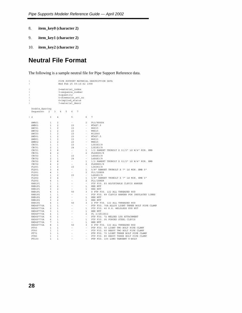
The following is a sample neutral file for Pipe Support Reference data.
! PIPE SUPPORT MATERIAL DESCRIPTION DATA! Wed Feb 25 09:16:42 1998
! 2=material_index! 3=sequence_number! 4=quantity! 5=dimension_att_no! 6=implied_status! 7=material_descr
Double_SpacingSequence= 2 3 4 5 6 7
! 2 3 4 5 6 7
AWA01 1 2 - 2 PL3/8X4X4AWB01 1 2 23 - WT4X7.5AWC01 1 2 23 - W6X15AWC02 1 2 23 - W8X15AWC03 1 2 23 - W12X40AWD01 1 2 23 - WT4X7.5AWE01 1 2 23 - W6X15AWE02 1 2 23 - W8X15CBC01 1 1 23 - L3X3X3/8CBC01 2 1 24 - L3X3X3/8CBC01 3 8 - 1 1/2 RAMSET TRUBOLT X 51/2" LG W/4" MIN. EMBCBC01 4 2 - 2 PL6X6X3/8CBC02 1 1 23 - L4X4X3/8CBC02 2 1 24 - L4X4X3/8CBC02 3 8 - 1 1/2 RAMSET TRUBOLT X 51/2" LG W/4" MIN. EMBCBC02 4 2 - 2 PL8X8X3/8FLD01 1 2 23 - L3X3X3/8FLD01 3 4 - 1 5/8" RAMSET TRUBOLT X 7" LG MIN. EMB 5"FLD01 4 1 - 2 PL1/2X8X8FLD02 1 2 23 - L4X4X3/8FLD02 3 4 - 1 5/8" RAMSET TRUBOLT X 7" LG MIN. EMB 5"FLD02 4 1 - 2 PL1/2X8X8RHB1P1 1 1 - - PTP FIG. 83 ADJUSTABLE CLEVIS HANGERRHB1P1 2 2 - 1 HEX NUTRHB1P1 3 2 - 1 HEX NUTRHB1P1 4 1 50 3 $ PTP FIG. 122 ALL THREADED RODRHB1P2 1 1 - - PTP FIG. 89 CLEVIS HANGER FOR INSULATED LINESRHB1P2 2 2 - 1 HEX NUTRHB1P2 3 2 - 1 HEX NUTRHB1P2 4 1 50 3 $ PTP FIG. 122 ALL THREADED RODRHD6P770A 1 1 - - PTP FIG. 70A ALLOY LIGHT THREE BOLT PIPE CLAMPRHD6P770A 2 1 - 1 PTP FIG. 40 R.H. WELDLESS EYE NUTRHD6P770A 3 1 - 1 HEX NUTRHD6P770A 4 1 - 2 PL 3/4X12X12RHD6P770A 5 1 - - PTP FIG. 72 WELDED LUG ATTACHMENTRHD6P770A 6 1 - 1 PTP FIG. 95 FORGED STEEL CLEVISRHD6P770A 7 1 - 1 HEX NUTRHD6P770A 8 1 50 3 $ PTP FIG. 122 ALL THREADED RODPT50 1 1 - - PTP FIG. 50 LIGHT TWO BOLT PIPE CLAMPPT60 1 1 - - PTP FIG. 60 HEAVY TWO BOLT PIPE CLAMPPT70 1 1 - - PTP FIG. 70 LIGHT THREE BOLT PIPE CLAMPPT80 1 1 - - PTP FIG. 80 HEAVY THREE BOLT PIPE CLAMPPT100 1 1 - - PTP FIG. 100 LONG TANGENT U-BOLT
28

2. Pip
e Su
pp
orts
Referen
ce Data
Pipe Support Material Reference Data Table 242________________
Sample Files
A sample neutral file for US practice is delivered in the file win32app\ingr\rdusrdb\spec_data\tab242.txt.
29
Pipe Supports Modeler Reference Guide — April 2002________________
2.2.2 Pipe Support Material Description Data Table243
During the support placement process, PPSM uses support commodity code and its design parameters selectedby the user to retrieve the material_index value from table 242. Subsequently, this value is used to retrieve thedetail description such as Cantilever member name of each sub-component that is applied to the support item.
Table 243 contains detail material description data of specific support commodity items.
The Pipe Support Material Description Data Table contains 7 attributes.
1. system_unique_no (integer)
2. material_index (character 16) This attribute matches the attribute 6 of table 242 and attribute 44 ofdesign database table 80. This attribute value is the linked access key between table 242, 243 and designtable 80 for a support commodity item with specific design parameters.
3. sequence_number (short) This attribute contains the material annotation takeoff sequence number perspecific design support commodity item. This sequence number is also used as an identifier of supportcomponents for the Eden module during the graphic placement.
4. quantity (short) This attribute contains the quantity of the item described by the material descriptionattribute 8.
5. dimention_att_no (short) This attribute contains the link for retrieval of the variable design dimensionaldata of support sub-component from the design table 80. The value is attribute number of table 80. Forexample, the value of 23 indicates the support design dimensional data of the item must be retrieved fromattribute 23 of table 80. The value of zero indicates this attribute is unused, the variable designdimensional data does not apply to the component item.
6. implied_item (short) This attribute designates whether the item identified is actually seen in the designfile or the item’s existence is implied. A value of one (1) means the item is implied. For example, thebolts and nuts material description of following sample data’s CBA Sequence No 3 entry is considered tobe an implied item. This implied item will be ignored by the Eden module during the graphic placement.The value of (2) means the item is structural plate item.
30

2. Pip
e Su
pp
orts
Referen
ce Data
Pipe Support Material Description Data Table 243________________
7. material_description (character*80) This attribute contains sub-component material description for aspecified support item.
The Plate material item name string must be delimited by ’X’ to separate plate’s three numericdimension values. For example:
"PLT 1/8X10X10" valid"1/8X10X10 PL" valid"PL5 X 3 X 5/8" valid"2PL3/8 X 2 X 5" invalid"PLT. 0.5 X 3/5" invalid
Neutral File Format
The following is a sample neutral file for the Pipe Support Material Description data.
! PIPE SUPPORT MATERIAL DESCRIPTION DATA! Wed Feb 25 09:16:42 1998
! 2=material_index! 3=sequence_number! 4=quantity! 5=dimension_att_no! 6=implied_status! 7=material_descr
Double_SpacingSequence= 2 3 4 5 6 7
! 2 3 4 5 6 7
AWA01 1 2 - 2 PL3/8X4X4AWB01 1 2 23 - WT4X7.5AWC01 1 2 23 - W6X15AWC02 1 2 23 - W8X15AWC03 1 2 23 - W12X40AWD01 1 2 23 - WT4X7.5AWE01 1 2 23 - W6X15AWE02 1 2 23 - W8X15CBC01 1 1 23 - L3X3X3/8CBC01 2 1 24 - L3X3X3/8CBC01 3 8 - 1 1/2 RAMSET TRUBOLT X 51/2" LG W/4" MIN. EMBCBC01 4 2 - 2 PL6X6X3/8CBC02 1 1 23 - L4X4X3/8CBC02 2 1 24 - L4X4X3/8CBC02 3 8 - 1 1/2 RAMSET TRUBOLT X 51/2" LG W/4" MIN. EMBCBC02 4 2 - 2 PL8X8X3/8FLD01 1 2 23 - L3X3X3/8FLD01 3 4 - 1 5/8" RAMSET TRUBOLT X 7" LG MIN. EMB 5"FLD01 4 1 - 2 PL1/2X8X8FLD02 1 2 23 - L4X4X3/8FLD02 3 4 - 1 5/8" RAMSET TRUBOLT X 7" LG MIN. EMB 5"FLD02 4 1 - 2 PL1/2X8X8RHB1P1 1 1 - - PTP FIG. 83 ADJUSTABLE CLEVIS HANGERRHB1P1 2 2 - 1 HEX NUTRHB1P1 3 2 - 1 HEX NUTRHB1P1 4 1 50 3 $ PTP FIG. 122 ALL THREADED RODRHB1P2 1 1 - - PTP FIG. 89 CLEVIS HANGER FOR INSULATED LINESRHB1P2 2 2 - 1 HEX NUTRHB1P2 3 2 - 1 HEX NUTRHB1P2 4 1 50 3 $ PTP FIG. 122 ALL THREADED RODRHD6P770A 1 1 - - PTP FIG. 70A ALLOY LIGHT THREE BOLT PIPE CLAMPRHD6P770A 2 1 - 1 PTP FIG. 40 R.H. WELDLESS EYE NUTRHD6P770A 3 1 - 1 HEX NUT
31
Pipe Supports Modeler Reference Guide — April 2002________________
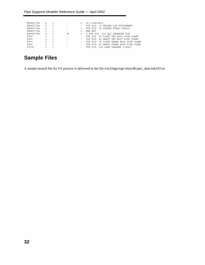
RHD6P770A 4 1 - 2 PL 3/4X12X12RHD6P770A 5 1 - - PTP FIG. 72 WELDED LUG ATTACHMENTRHD6P770A 6 1 - 1 PTP FIG. 95 FORGED STEEL CLEVISRHD6P770A 7 1 - 1 HEX NUTRHD6P770A 8 1 50 3 $ PTP FIG. 122 ALL THREADED RODPT50 1 1 - - PTP FIG. 50 LIGHT TWO BOLT PIPE CLAMPPT60 1 1 - - PTP FIG. 60 HEAVY TWO BOLT PIPE CLAMPPT70 1 1 - - PTP FIG. 70 LIGHT THREE BOLT PIPE CLAMPPT80 1 1 - - PTP FIG. 80 HEAVY THREE BOLT PIPE CLAMPPT100 1 1 - - PTP FIG. 100 LONG TANGENT U-BOLT
Sample Files
A sample neutral file for US practice is delivered in the file win32app\ingr\rdusrdb\spec_data\tab243.txt.
32
2. Pip
e Su
pp
orts
Referen
ce Data
Support User-Interface Definition Form and Table________________
2.3 Support User-Interface DefinitionForm and Table
For each pipe support standard or each pipe support component to be placed, the Eden modules must be createdand the User-Interface Definition Form and Tutorial Definition Table that define the pipe support’s modelingrequirements. The name of the form and the table has been specified by the table 241 attribute 3,support_commodity_name.
The Support User-interface Definition Form and Table allows definition of any specific input or dimensionalrequirements of the pipe support standard. The Eden modules, written for a given support standard, will use thedata generated by the user-interface definitions extensively.
The Support User-interface definition forms can be created using DBACESS. It contains the pipe support’sgraphic symbol representation and the input fields required for the support placement. The specific dimensiondata and various design data can be collected and sent to the Eden symbol logic processor.
The Support Tutorial Definition Table can be created and edited using an ASCII editor. Each input field in theUser-interface Definition form must have a corresponding row in the Tutorial Definition Table.
The Support User-Interface Definition Table provides a flexible tool allowing the user to define different inputrequirements for the support placement. User has total control in defining various support placementmethodologies, it provides the data or commands interaction between user and the Eden module.
The Support Tutorial Definition Table record contains 6 fields:
Field Number
Data Type
Global Variable
Input Attribute
Default String
Field Name
The concept of the support User-interface Definition Form and Table is an enhancement of the capability thatcurrently exists in the PDS Equipment module. The definition table capability is expanded and modified tomeet the pipe support requirements. For detailed descriptions and concept of the definition table, please refer tothe PDS Eden Interface Reference Guide – Volume 2: Equipment tutorial definition table section and the PDSEden Interface Reference Guide — Volume 3: Pipe Supports.
33

Pipe Supports Modeler Reference Guide — April 2002________________
34

3. Pip
e Su
pp
orts
Mo
deler
Pipe Supports Modeler________________
3. Pipe Supports Modeler
The Pipe Supports Modeler provides accurate modeling of detailed pipe supports through interactive forms.Pipe supports are modeled in existing piping models in your project. They act as intelligent componentsattached to the pipe. (When you move or delete a pipeline, the connected supports respond accordingly.) TheSupport Modeler reads FrameWorks Plus data from identified structural and steel components, eliminating theneed to re-enter data to place the support.
You can access the Pipe Supports Modeler from three different points in the PDS interface.
From PD_Shell — Select Pipe Support Modeling
From Pipe Support Explorer — Highlight the model and select Pipe Supports Modeler
From Piping Designer — Select Switch to Pipe Support from the File options palette.
Option Descriptions
Supports — The Supports commands is used to place and revise supports and review and analyze data.
View — The View commands is used to modify what is seen in the selected views. These commandsonly manipulate the view of the model, they do not manipulate the actual model.
File — The File commands is used to plot and diagnose problems in design files. They also allowdefinition of the active options for the file and what reference models are attached and displayed.
Element — The Element commands provides access to the Analyze command.
Settings — The Settings commands provides the ability to modify rendering, fonts and colors usedduring a graphics session.
User — The User commands provides access to PDS help and to the user preferences and buttonassignments that are specific to your system.
Applications — The Applications commands provides information regarding the applications currentlyrunning associated with PDS.
35

Pipe Supports Modeler Reference Guide — April 2002________________
3.1 Supports Commands
The Supports commands are used to place and revise supports and review and analyze data.
Commands
Place — The Place command is used to place pipe supports, copy pipe supports, place physical pipesupports and place logical pipe supports.
Revise Support — The Revise Support command is used to revise pipe support attributes, create asupport group, create a support gang, move a pipe support or delete a pipe support.
Review Data — The Review Data command is used to review attributes, nozzle data, reports andtemporary symbology data.
Analyze Data — The Analyze Data command is used to review DesignReview tags, perform pipingclash review or piping clash check, perform design check review or review the RDB report.
Operating Sequence
The following sequence is used to place all supports.
1. Select the Place support icon.
2. Select the support group.
3. Select the support detail.
4. Select the FrameWorks Plus structure, Equipment, or Point in space command as required.
5. Select Confirm to accept or type a tag in the tag field displayed.
36

3. Pip
e Su
pp
orts
Mo
deler
Pipe Support Place Commands________________
3.1.1 Pipe Support Place Commands
The Place commands are used to place pipe supports, copy pipe supports, place physical pipe support, and placelocal pipe support.
Commands
Place Pipe Supports — Places pipe supports for the selected piping model.
Copy Pipe Support — Copies pipe supports for the selected piping model.
Physical Pipe Support — Places a physical pipe support in the selected piping model.
Logical Pipe Support — Places a logical pipe support in the selected piping model.
37
Pipe Supports Modeler Reference Guide — April 2002________________
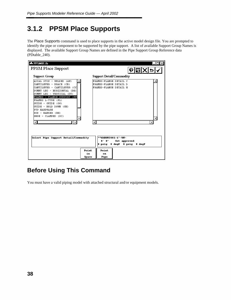
3.1.2 PPSM Place Supports
The Place Supports command is used to place supports in the active model design file. You are prompted toidentify the pipe or component to be supported by the pipe support. A list of available Support Group Names isdisplayed. The available Support Group Names are defined in the Pipe Support Group Reference data(PDtable_240).
Before Using This Command
You must have a valid piping model with attached structural and/or equipment models.
38
3. Pip
e Su
pp
orts
Mo
deler
PPSM Place Supports________________
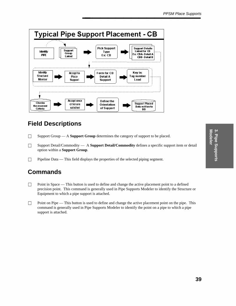
Field Descriptions
Support Group — A Support Group determines the category of support to be placed.
Support Detail/Commodity — A Support Detail/Commodity defines a specific support item or detailoption within a Support Group.
Pipeline Data — This field displays the properties of the selected piping segment.
Commands
Point in Space — This button is used to define and change the active placement point to a definedprecision point. This command is generally used in Pipe Supports Modeler to identify the Structure orEquipment to which a pipe support is attached.
Point on Pipe — This button is used to define and change the active placement point on the pipe. Thiscommand is generally used in Pipe Supports Modeler to identify the point on a pipe to which a pipesupport is attached.
39
Pipe Supports Modeler Reference Guide — April 2002________________
Operating Sequence
1. Identify Component or Pipe — Select the pipe or component to be supported, then accept the locateditem.
— OR —
Select the Point on Pipe command.
See the Point on Pipe section for more information about this command.
2. Select Pipe Support Group — Select the category of support to place a list of Support Commoditieswhich meet the design requirements for the selected Support Group is displayed.
3. Select Pipe Support Detail/Commodity — Select the specific type of support to place.
4. Identify Structure or Equipment — Select the existing structure or equipment to attach the supportcommodity. Use a Tentative Snap, then approve the highlighted item.
— OR —
Select Point in Space.
See the Point in Space section for more information about this command.
User arbitrary sections are not supported.
5. Accept or Place Support or Select Other Option — Select confirm to place the support. Dependingon the type of support being placed, the system displays a form for the selected commodity’s user-interface definition after the Support Commodity Name is selected. Type the attribute information for thesupport and select Accept. See Delivered Pipe Supports, page 43 Delivered Pipe Supports forinformation about different attributes for each support type.
The Orientation Tee displays on the form relative to the layout of the support.
6. Define Orientation — Select standard orientation from the form or type an angle to define the Primaryand Secondary orientation. Select Confirm to accept orientation definition.
The system places the support using the identified pipe and Structural/Equipment item and the suppliedattribute information.
40
3. Pip
e Su
pp
orts
Mo
deler
Point In Space________________
3.1.2.1 Point In Space
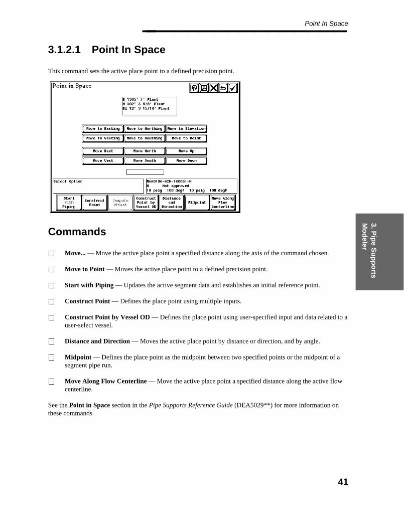
This command sets the active place point to a defined precision point.
Commands
Move... — Move the active place point a specified distance along the axis of the command chosen.
Move to Point — Moves the active place point to a defined precision point.
Start with Piping — Updates the active segment data and establishes an initial reference point.
Construct Point — Defines the place point using multiple inputs.
Construct Point by Vessel OD — Defines the place point using user-specified input and data related to auser-select vessel.
Distance and Direction — Moves the active place point by distance or direction, and by angle.
Midpoint — Defines the place point as the midpoint between two specified points or the midpoint of asegment pipe run.
Move Along Flow Centerline — Move the active place point a specified distance along the active flowcenterline.
See the Point in Space section in the Pipe Supports Reference Guide (DEA5029**) for more information onthese commands.
41
Pipe Supports Modeler Reference Guide — April 2002________________
3.1.2.2 Point on Pipe
This command allows you to define and change the active placement data on a piping segment.
Operating Sequence
1. Identify Pipe End — Select the pipe or component to be supported, to locate the connect point.
2. Specify Distance from Pipe End or Accept Mid Point on Pipe — Type the distance to move from theselected point in working units or select Confirm to select the midpoint of the pipe.
42
3. Pip
e Su
pp
orts
Mo
deler
Delivered Pipe Supports________________
3.1.3 Delivered Pipe Supports
The following user inputs are required for individual delivered supports.
Cantilever Braced
Tag — The support tag number. Expected value is any alphanumeric value.
Angle — The angle at which the brace is inclined with the Cantilever. Expected value is default 45 deg.
Load — The load on the support as defined by the moment force unit in Project Administrator >Project Data Manager > Seed > Piping Model > Revise > Physical Units.
L — The distance of pipe from the structure selected. This value is automatically filled. The value canbe edited.
Item_type — The structural member type for drawing the support graphics. This value is automaticallyfilled if moment cal. is less than allow.moment.
— OR —
1,2 : L-Section3,4 : I-Section5 : Box
Mark Number — The mark number available only in review mode. This value is automatically filled.
Cantilever Cantilever
Tag — The support tag number. Expected value is any alphanumeric value.
Load — The load on the support as defined by the moment force unit in Project Administrator >Project Data Manager > Seed > Piping Model > Revise > Physical Units.
L — The length of cantilever. This value is automatically filled. The value can be edited.
Item_type — The structural member type for drawing the support graphics. This value is automaticallyfilled if moment cal. is less than allow.moment.
— OR —
1,2,3 : L-Section4,5 : Channel Section6,7,8 : I-Section9 10 : Box Section
43
Pipe Supports Modeler Reference Guide — April 2002________________ Shoe Height — The gap between cantilever and pipe to insert the shoe. This value is default 0’ 0".
Pipe to steel distance — This gives the distance between the pipe and structure. This value isautomatically filled, but only in review mode.
Mark Number — The mark number available only in review mode. This value is automatically filled.
Dummy Leg Horizontal
Tag — The support tag number. Expected value is any alphanumeric value.
Load — The load on the support as defined by the moment force unit in Project Administrator >Project Data Manager > Seed > Piping Model > Revise > Physical Units.
L — The length of cantilever. This value is automatically filled. The value can be edited.
Legsize — The Dummy Leg size. This value is automatically filled from the dimension table.
Schedule — The schedule of the dummy leg. This value is automatically filled.
Mark Number — The mark number available only in review mode. This value is automatically filled.
Dummy Leg Vertical
The only way that a Dummy Leg Vertical support can be placed is through using the Point in Space command.You cannot place the support correctly if you identify the structure (concrete slab or horizontal beam).
Tag — The support tag number. Expected value is any alphanumeric value.
Load — The load on the support as defined by the moment force unit in Project Administrator >Project Data Manager > Seed > Piping Model > Revise > Physical Units.
L — The length of cantilever. This value is automatically filled. The value can be edited.
Legsize1 — The Top Dummy Leg size. This value is automatically filled from the dimension table.
Legsize2 — The Bottom Dummy Leg size. This value is automatically filled (where applicable) from thedimension table.
Material Code — Only three material codes are allowed for dummy leg vertical. Default is C.
C = Carbon Steel (ASTM A106 Gr.B)A = Alloy Steel (ASTM A335 Gr. P22)S = Stainless Steel (ASTM A312 Gr. TP304L)
Schedule for First Leg — The schedule of top dummy leg. This value is automatically filled.
44
3. Pip
e Su
pp
orts
Mo
deler
Delivered Pipe Supports________________ Schedule for Second Leg — The schedule of bottom dummy leg, where applicable. This value isautomatically filled.
Mark Number — The mark number available only in review mode. This value is automatically filled.
Frames Flanged
Tag — The support tag number. Expected value is any alphanumeric value.
Load — The load on the support as defined by the moment force unit in Project Administrator >Project Data Manager > Seed > Piping Model > Revise > Physical Units.
Rating — The pressure rating of the flange associated with the support.
Height — The length of a vertical member. This is a numerical value, maximum 36".
Bolt Material Type — Material type of the bolts associated with the flange.
Mark Number — The mark number available only in review mode. This value is automatically filled.
Frames L-Type
Tag — The support tag number. Expected value is any alphanumeric value.
Load — The load on the support as defined by the moment force unit in Project Administrator >Project Data Manager > Seed > Piping Model > Revise > Physical Units.
L — The length of a horizontal member. This is a numerical value, maximum 18".
Height — The length of a vertical member. This is a numerical value, maximum 36".
Is Item 1 Subject to Torsion — This indicates whether the vertical member is in torsion. Accordingly,allows certain sections to be used. The value is Y/N (yes or no).
Pipe Movement — Pipe movement is used for moment calculations. This is a numerical value in inches.
Mx — Moment in X-direction. This is used for moment calculations.
My — Moment in Y-direction. This is used for moment calculations.
Mz — Moment in Z-direction. This is used for moment calculations.
45
Pipe Supports Modeler Reference Guide — April 2002________________ Item_type — The structural member type for drawing the support graphics. This value is automaticallyfilled if moment cal. is less than allow.moment.
— OR —
1,2 : L-Section3 : Channel Section4 : I-Section5,6,7 : Box Section
Item_Type Second digit Configuration — The Item_Type gives the support configuration as shown inthe standard.
A = Horizontal pipe and Item type = 1/2B = Vertical pipe and Item type = 1,2C = Horizontal pipe and Item type = 3D = Vertical pipe and Item type = 3E = Horizontal pipe and Item type = 4F = Horizontal pipe and Item type = 5,6,7G = Vertical pipe and Item type = 5,6,7
Mark Number — The mark number available only in review mode. This value is automatically filled.
Guide Guide
Tag — The support tag number. Expected value is any alphanumeric value.
Shoe width or Pipe OD — The distance between two guides. This value is automatically filled.
Pipe to steel distance — The distance from pipe to place guides. This value is automatically filled. Thevalue may be edited.
Mark Number — The mark number available only in review mode. This value is automatically filled.
Guide Holddown
Tag — The support tag number. Expected value is any alphanumeric value.
Base Plate width — The plate width for which the guide is being placed. This value is automaticallyfilled.
Pipe to steel distance — The distance from pipe to place guides. This value is automatically filled. Thisvalue may be edited.
Mark Number — The mark number available only in review mode. This value is automatically filled.
46
3. Pip
e Su
pp
orts
Mo
deler
Delivered Pipe Supports________________
Rod Hanger
Tag — The support tag number. Expected value is any alphanumeric value.
Load — The load on the support as defined by the weight unit in Project Administrator > Project DataManager > Seed > Piping Model > Revise > Physical Units.
Bottom Attachment — The attachment with pipe. Select from the list. (Make sure that you press theEnter or Tab button after selection).
Top Attachment — The attachment with steel. Select from the list. (Make sure that you press the Enteror Tab button after selection).
Material Code — The material used to make the rod hanger.
C = Carbon SteelA = Alloy SteelS = Stainless Steel
Mark Number — The mark number available only in review mode. This value is automatically filled.
Vessel Guide
Tag — The support tag number. Expected value is any alphanumeric value.
Load — The load on the support as defined by the moment force unit in Project Administrator >Project Data Manager > Seed > Piping Model > Revise > Physical Units.
L — The distance of pipe from the structure selected. This value is automatically filled. The value maybe edited.
Item_type — The structural member type for drawing the support graphics. This value is automaticallyfilled if moment cal. is less than allow.moment.
— OR —
For Detail A = 1 to 6For Detail B = 1,2For Detail C = 1,2,3
Pipe to Steel — The distance from the pipe to structure. This value is automatically filled and is only forreview mode.
Mark Number — The mark number available only in review mode. This value is automatically filled.
47
Pipe Supports Modeler Reference Guide — April 2002________________
Shoe Clamped
Tag — The support tag number. Expected value is any alphanumeric value.
Height — The length of a vertical member. This is a numerical value, maximum 36".
L — The length of a horizontal member. This is a numerical value, maximum 18".
Mark Number — The mark number available only in review mode. This value is automatically filled.
Shoe Welded
Tag — The support tag number. Expected value is any alphanumeric value.
Height — The length of a vertical member. This is a numerical value, maximum 36".
L — The length of a horizontal member. This is a numerical value, maximum 18".
Mark Number — The mark number available only in review mode. This value is automatically filled.
Variable Spring Hanger
Tag — The support tag number. Expected value is any alphanumeric value.
Type — Hanger type. Select from list (1, 2, 4, 6, 8). (Make sure that you press <Enter> or <Tab> afterselection.)
Size — Hanger size. Refer to Appendix B for discussions of spring hangers. Expected values are 0, 10,20, 30, 40, 50, 60, 70, 80, 90, 100, 110, 120, 130, 140, 150, 160, 170, 180, 190, 200, 210 and 220.
Load — The load on the support as defined by the weight unit in Project Administrator > Project DataManager > Seed > Piping Model > Revise > Physical Units.
Bottom Attachment — The attachment with pipe. Select from the list. (Make sure that you press<Enter> or <Tab> after selection.) See Appendix A for descriptions.
Top Attachment — The attachment with steel. Select from the list. (Make sure that you press <Enter>or <Tab> after selection.) See Appendix A for descriptions.
Plate Attachment — Plate attachments required for supports to be placed on concrete. Select from list.(Make sure that you press <Enter> or <Tab> after selection.) See Appendix A for descriptions.
c_c dimension — Center to center distance between two springs. This input is only required when thebottom attachment B6 is used. See Appendix A for descriptions.
Shoe height or Pipe CL to hanger — Required for bottom attachment B6 only. See Appendix A fordescription.
48
3. Pip
e Su
pp
orts
Mo
deler
Delivered Pipe Supports________________ Total Travel — Value in inches or mm.
Hydrotest load — Test load as defined by the weight unit in Project Administrator > Project DataManager > Seed > Piping Model > Revise > Physical Units.
Mark Number — The mark number available only in review mode. This value is automatically filled.
Vessel Support
Tag — The support tag number. Expected value is any alphanumeric value.
Load — The load on the support as defined by the moment force unit in Project Administrator >Project Data Manager > Seed > Piping Model > Revise > Physical Units.
L — The distance of pipe from the structure selected. This value is automatically filled. The value maybe edited.
Width — The width of a horizontal section. This is a numerical value. Maximum values for each detailvaries and gets updated if the user exceeds the value.
Item_type — The structural member type for drawing the support graphics. This value is automaticallyfilled if moment cal. is less than allow.moment.
— OR —
For Detail A = 1 (dia <=4), 2 (dia >=6)For Detail B = 1 (dia <= 28), 2 (dia <=42)For Detail C = 1For Detail D = 1For Detail E = 1For Detail F = 1,2,3,4,5,6For Detail G = 1,2
Mark Number — The mark number available only in review mode. This value is automatically filled.
49
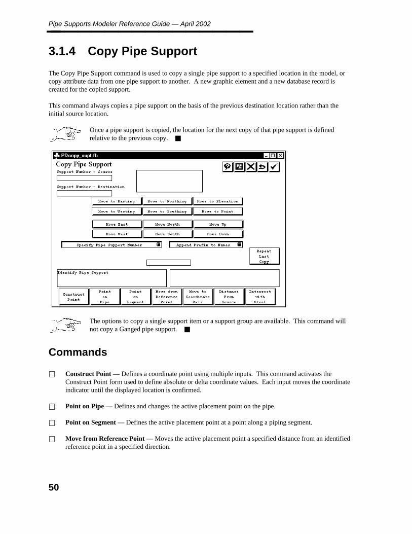
Pipe Supports Modeler Reference Guide — April 2002________________
3.1.4 Copy Pipe Support
The Copy Pipe Support command is used to copy a single pipe support to a specified location in the model, orcopy attribute data from one pipe support to another. A new graphic element and a new database record iscreated for the copied support.
This command always copies a pipe support on the basis of the previous destination location rather than theinitial source location.
Once a pipe support is copied, the location for the next copy of that pipe support is definedrelative to the previous copy.
The options to copy a single support item or a support group are available. This command willnot copy a Ganged pipe support.
Commands
Construct Point — Defines a coordinate point using multiple inputs. This command activates theConstruct Point form used to define absolute or delta coordinate values. Each input moves the coordinateindicator until the displayed location is confirmed.
Point on Pipe — Defines and changes the active placement point on the pipe.
Point on Segment — Defines the active placement point at a point along a piping segment.
Move from Reference Point — Moves the active placement point a specified distance from an identifiedreference point in a specified direction.
50

3. Pip
e Su
pp
orts
Mo
deler
Copy Pipe Support________________ Move Coordinate Axis — Determines the active placement point as the intersection of a specified piperun with a coordinate axis and corresponding coordinate value.
Distance From Source — Places the copied (new) pipe support a specified distance from the originalsupport.
Intersect with Steel Point on Segment — Defines the active placement point at a point along a pipingsegment.
Point on Pipe — Defines and changes the active placement point on a pipe.
Repeat Last Copy — Places a series of incremental copies by repeating the previous copy operation.This command copies the previously identified pipe support and moves the same distance and directionfrom the last copy point. Each time this option is selected, the copy is performed incrementally from thelast copy point.
Specify Pipe Support Number/Do NOT Specify Pipe Support Number — Specify Pipe SupportNumber allows you to enter the destination support number in the field below the toggles. Do NOTSpecify Pipe Support Number allows you to either define the destination support number to be the sameas the source support number or to use the source support number, but with two asterisks appended.
Append Prefix to Names/No Prefix for Names — Defines the destination support number to be thesame as the source support number or to use the source support number with two asterisks appended.
Field Descriptions
Support Number - Source — Displays the pipe support number of the support to copy from.
Support Number - Destination — Displays the pipe support number of the new pipe support. Type thenumber in the field below the toggles, if the toggle Specify Pipe Support is set.
If toggle is set to Do NOT Specify Pipe Support Number and the second toggle is set to Append Prefix toNames, two asterisks are appended to the Source Support Name.
New Pipe Support Number — Prompts to type a pipe support number for the new pipe support. Enteredtext displays in the New Support Number field.
Before using this command
The pipe support to be copied must exist in the active model or in a reference file. The correspondingreference file snap and/or locate locks must be enabled for the reference file.
The piping segment on which the new pipe support will be placed must exist in the active model.
51
Pipe Supports Modeler Reference Guide — April 2002________________
Operating Sequence
1. Identify Pipe Support places a data point to locate the pipe support to be copied. The pipe support to becopied is highlighted when selected.
2. Press <D> to accept the identified pipe support.
3. Enter New Pipe Support Number typing a pipe support number for the new support in the New PipeSupport Number field.
4. Specify Support Location by snapping to a segment end or vertex or select any of the Precision Inputoptions to identify the location for the new pipe support. A segment must exist at the specified location.The highlighted pipe support is copied to the new location and the new database information is created.The linkage is also updated on the pipe support.
52
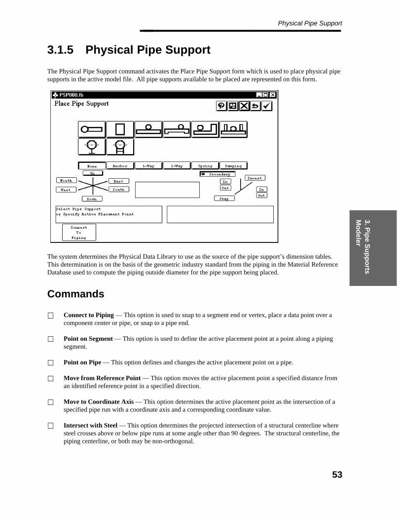
3. Pip
e Su
pp
orts
Mo
deler
Physical Pipe Support________________
3.1.5 Physical Pipe Support
The Physical Pipe Support command activates the Place Pipe Support form which is used to place physical pipesupports in the active model file. All pipe supports available to be placed are represented on this form.
The system determines the Physical Data Library to use as the source of the pipe support’s dimension tables.This determination is on the basis of the geometric industry standard from the piping in the Material ReferenceDatabase used to compute the piping outside diameter for the pipe support being placed.
Commands
Connect to Piping — This option is used to snap to a segment end or vertex, place a data point over acomponent center or pipe, or snap to a pipe end.
Point on Segment — This option is used to define the active placement point at a point along a pipingsegment.
Point on Pipe — This option defines and changes the active placement point on a pipe.
Move from Reference Point — This option moves the active placement point a specified distance froman identified reference point in a specified direction.
Move to Coordinate Axis — This option determines the active placement point as the intersection of aspecified pipe run with a coordinate axis and a corresponding coordinate value.
Intersect with Steel — This option determines the projected intersection of a structural centerline wheresteel crosses above or below pipe runs at some angle other than 90 degrees. The structural centerline, thepiping centerline, or both may be non-orthogonal.
53

Pipe Supports Modeler Reference Guide — April 2002________________
Field Descriptions
Coordinate Readout — Displays the coordinate readout for the location of the Active Placement Point inthe active coordinate system once you have connected to piping.
The Place Pipe Support form may be redefined. The PDS Eden Interface document explains therelationship between the Place Pipe Support form and the actual pipe support symbols.
This option respects the definition of groups of pipe supports in the component menu selection part of the form.
Before using this option Ensure that a piping segment exists at the intended pipe supportlocation. All pipe supports are linked to piping segments.
1. Specify Active Placement Point by using the Connect to Pipe command, which is activated by default.You can snap to a segment end or vertex, place a data point over a component center or pipe, or snap to apipe end. You can also use the Precision Input commands on the bottom of the form.
2. Select Pipe Support by selecting the symbol(s) representing the pipe support(s) to be placed. Thesystem activates the corresponding Symbol form.
3. Accept to Place Pipe Support or Select Other Option by setting the primary and secondaryorientations of the pipe support using the orientation controls.
54
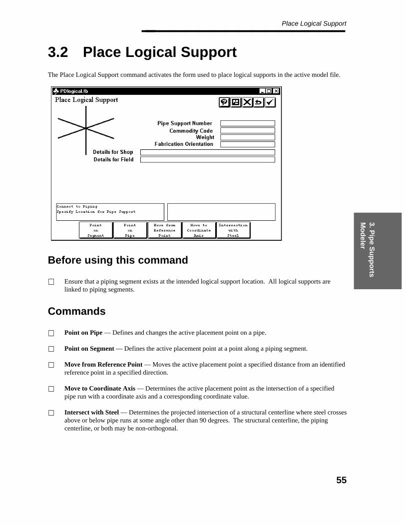
3. Pip
e Su
pp
orts
Mo
deler
Place Logical Support________________
3.2 Place Logical Support
The Place Logical Support command activates the form used to place logical supports in the active model file.
Before using this command
Ensure that a piping segment exists at the intended logical support location. All logical supports arelinked to piping segments.
Commands
Point on Pipe — Defines and changes the active placement point on a pipe.
Point on Segment — Defines the active placement point at a point along a piping segment.
Move from Reference Point — Moves the active placement point a specified distance from an identifiedreference point in a specified direction.
Move to Coordinate Axis — Determines the active placement point as the intersection of a specifiedpipe run with a coordinate axis and a corresponding coordinate value.
Intersect with Steel — Determines the projected intersection of a structural centerline where steel crossesabove or below pipe runs at some angle other than 90 degrees. The structural centerline, the pipingcenterline, or both may be non-orthogonal.
55
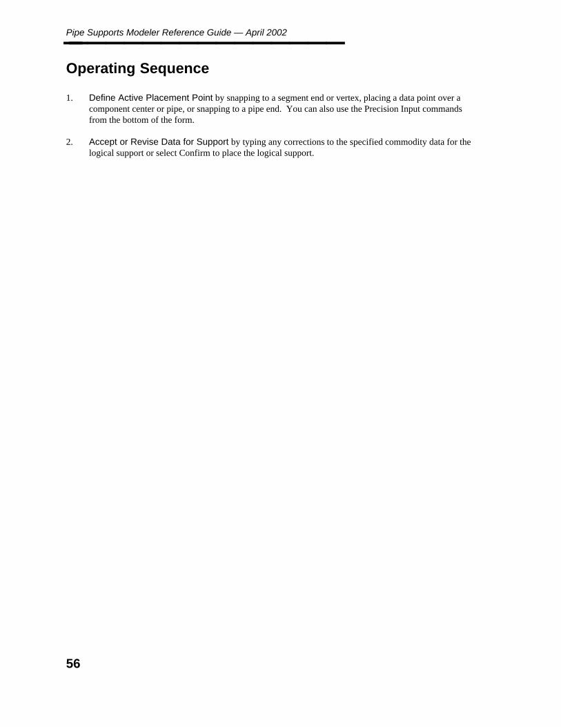
Pipe Supports Modeler Reference Guide — April 2002________________
Operating Sequence
1. Define Active Placement Point by snapping to a segment end or vertex, placing a data point over acomponent center or pipe, or snapping to a pipe end. You can also use the Precision Input commandsfrom the bottom of the form.
2. Accept or Revise Data for Support by typing any corrections to the specified commodity data for thelogical support or select Confirm to place the logical support.
56
3. Pip
e Su
pp
orts
Mo
deler
Revise Pipe Support Commands________________
3.3 Revise Pipe Support Commands
The Revise Support commands are used to revise pipe support attributes, create a support group, create asupport gang, move a pipe support or delete a pipe support.
Commands
Revise Pipe Support Attributes — Modifies the database attributes or user data associated with aselected element.
Create Support Group — Creates a grouping of two or more individual supports placed on the samepipe in the active model.
Create Support Gang — Create a ganging of two or more individual or group supports placed in theactive model on two or more pipes.
Move Pipe Support — Moves a pipe support to a new location on a piping segment.
Delete Pipe Support — Deletes a component, pipe or pipe support.
57

Pipe Supports Modeler Reference Guide — April 2002________________
3.3.1 Revise Attributes
The Revise Attributes command is used to modify the database attributes or user data associated with a selectedelement. The following information may be revised:
The database information of a pipe support.
The user data associated with a component, pipe support, segment or PDS marker.
This command displays the Revise Attribute form which is used to select the attribute or user data informationto be modified. When a new attribute value is entered, the system validates the entry and stores the revisedinformation in the database. If user data is changed, the system toggles the value among the acceptable settings.
Commands
Identify Element — Revises the data for another element. Identify the new element as previouslyspecified. The system displays the data retrieved from the element. Depending on the type of element,this may include one of the following conditions for each welded connect point for a piping component,instrument component, and pipe: shop weld defined by the system, shop weld defined by the user, fieldweld defined by the system, or field weld defined by the user.
You must ensure the format in the Standard Note Library is consistent with the remainder of theReference Database.
These options vary depending on the type of element identified. They provide the ability to jump directly to thespecified set of information within the display.
58
3. Pip
e Su
pp
orts
Mo
deler
Revise Attributes________________ The system also moves the coordinate system indicator along the identified element to reflect the data beingreviewed.
The user data can be used for a piping segment to revise the centerline offset data for a pipe runof a piping segment. Defining this data allows the Reconstruct Piping command to adjust thecenterline for placement of an offset from the centerline (such as placement by bottom of pipe).
Select a row that corresponds to an attribute using standard note type 499. The system displays a dialog boxwith the text for the piping notes. You can change the standard note number, but you cannot change the text forthe standard note.
Operating Sequence
1. Identify Element by snapping to the component, segment, or marker to be reviewed or place a data pointto locate a piping component.
2. Specify Attribute Value (Revisable Attribute) by typing the new attribute value. If the attribute iscode-listed, the system activates a form which lists the available code list for selection of the new value.
59
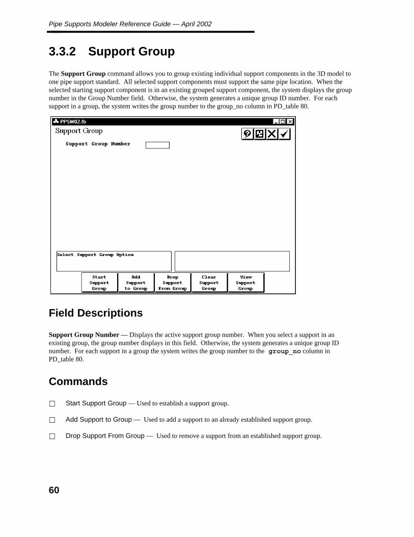
Pipe Supports Modeler Reference Guide — April 2002________________
3.3.2 Support Group
The Support Group command allows you to group existing individual support components in the 3D model toone pipe support standard. All selected support components must support the same pipe location. When theselected starting support component is in an existing grouped support component, the system displays the groupnumber in the Group Number field. Otherwise, the system generates a unique group ID number. For eachsupport in a group, the system writes the group number to the group_no column in PD_table 80.
Field Descriptions
Support Group Number — Displays the active support group number. When you select a support in anexisting group, the group number displays in this field. Otherwise, the system generates a unique group IDnumber. For each support in a group the system writes the group number to the group_no column inPD_table 80.
Commands
Start Support Group — Used to establish a support group.
Add Support to Group — Used to add a support to an already established support group.
Drop Support From Group — Used to remove a support from an established support group.
60

3. Pip
e Su
pp
orts
Mo
deler
Support Group________________ Clear Support Group — Used to remove an entire support group.
View Support Group — Used to view a support group.
Operating Sequence
For the following commands, the pipe support group can be selected in two ways:
Select a support in the group.
— OR —
Type the support group number in the Support Group field and press <Enter> or <Tab>.
Identify Support for Group
1. Identify and accept the first support for the group.
The system displays the assigned support group number in the Support Group field.
2. Select consecutive supports to be placed in the same group.
The system displays the message Support has been added to group.
Add Support to Group
1. Identify support group.
2. Select consecutive supports to be added to the same group.
The system displays the message Support has been added to group.
Drop Support from Group
1. Identify the support group to be dropped.
2. Identify support to drop from the support group.
3. Select Confirm to accept.
The system displays the message Support has been dropped from group.
Clear Support Group
1. Identify the support group to be cleared.
2. Select Confirm to accept.
61

Pipe Supports Modeler Reference Guide — April 2002________________ The system displays the message Support group has been cleared.
View Support Group
1. Identify the support group to be viewed.
2. The system highlights the selected Support Group.
62

3. Pip
e Su
pp
orts
Mo
deler
Support Gang________________
3.3.3 Support Gang
The Support Gang command allows you to group existing supports and support groups in the 3D model into a"ganged" support assembly. If the selected starting support component is an existing ganged supportcomponent, the system displays the gang number in the Gang Number field. Otherwise, the system generates aunique gang ID number. For each support in the gang, the system writes the gang number to the gang_nocolumn in PD_table 80. If the support selected is a member of a support group, all the other supports in thatgroup are added to the gang.
Field Descriptions
Support Gang Number — Displays the active support gang number. When you select a support in an existinggang, the support gang number displays in this field. Otherwise, the system generates a unique gang IDnumber. For each support in a gang the system writes the gang number to the gang_no column in PD_table80.
Commands
Start Support Gang — Used to establish a support gang.
Add Support to Gang — Used to add a support to an already established support gang.
Drop Support From Gang — Used to remove a support from an established support gang.
63

Pipe Supports Modeler Reference Guide — April 2002________________ Clear Support Gang — Used to remove an entire support gang.
View Support Gang — Used to view a support gang.
Operating Sequence
For the following commands, the pipe support gang can be selected in two ways:
Select a support in the gang.
— OR —
Type the support gang number in the Support Gang field and press <Enter> or <Tab>.
Start Support Gang
1. Identify and accept the first support for the gang.
The system displays the assigned support gang number in the Support Gang Number field.
2. Select consecutive supports to be placed in the same gang.
The system displays the message Support has been added to gang.
Add Support to Gang
1. Identify support gang.
2. Select supports or support groups to be added to the support gang.
The system displays the message Support has been added to gang.
Drop Support from Gang
1. Identify the Support Gang from which the support is to be dropped.
2. Identify Support to drop from the Support Gang.
3. Select Confirm to accept.
The system displays the message Support has been dropped from gang.
Clear Support Gang
1. Identify the Support Gang to be cleared.
2. Select Confirm to accept.
64

3. Pip
e Su
pp
orts
Mo
deler
Support Gang________________ The system displays the message Support gang has been cleared.
View Support Gang
1. Identify the support gang to be viewed.
2. The system highlights the selected Support Gang.
65
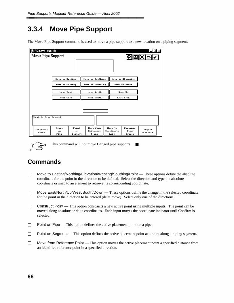
Pipe Supports Modeler Reference Guide — April 2002________________
3.3.4 Move Pipe Support
The Move Pipe Support command is used to move a pipe support to a new location on a piping segment.
This command will not move Ganged pipe supports.
Commands
Move to Easting/Northing/Elevation/Westing/Southing/Point — These options define the absolutecoordinate for the point in the direction to be defined. Select the direction and type the absolutecoordinate or snap to an element to retrieve its corresponding coordinate.
Move East/North/Up/West/South/Down — These options define the change in the selected coordinatefor the point in the direction to be entered (delta move). Select only one of the directions.
Construct Point — This option constructs a new active point using multiple inputs. The point can bemoved along absolute or delta coordinates. Each input moves the coordinate indicator until Confirm isselected.
Point on Pipe — This option defines the active placement point on a pipe.
Point on Segment — This option defines the active placement point at a point along a piping segment.
Move from Reference Point — This option moves the active placement point a specified distance froman identified reference point in a specified direction.
66

3. Pip
e Su
pp
orts
Mo
deler
Move Pipe Support________________ Move to Coordinate Axis — This option determines the active placement point as the intersection of aspecified pipe run with a coordinate axis and a corresponding coordinate value.
Distance from Source — This option places the copied (new) pipe support a specified distance from theoriginal support.
Compute Distance — This option moves the active placement point by a known offset.
Operating Sequence
1. Identify Pipe Support by snapping to the pipe support or place a data point to locate the pipe supportelement to be moved.
2. Specify New Location by defining the new location for the selected pipe support by using one of thefollowing methods: Use the Move To fields to specify an absolute coordinate change. Use the Movefields to specify a delta coordinate change from the reference point. Select the Construct Point optionfrom the form to use multiple inputs to define the point. Select the Compute distance option.
3. Accept or Specify New Location to redefine the location of the pipe support.
67
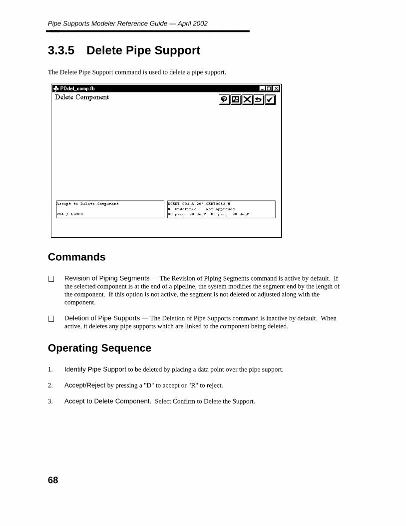
Pipe Supports Modeler Reference Guide — April 2002________________
3.3.5 Delete Pipe Support
The Delete Pipe Support command is used to delete a pipe support.
Commands
Revision of Piping Segments — The Revision of Piping Segments command is active by default. Ifthe selected component is at the end of a pipeline, the system modifies the segment end by the length ofthe component. If this option is not active, the segment is not deleted or adjusted along with thecomponent.
Deletion of Pipe Supports — The Deletion of Pipe Supports command is inactive by default. Whenactive, it deletes any pipe supports which are linked to the component being deleted.
Operating Sequence
1. Identify Pipe Support to be deleted by placing a data point over the pipe support.
2. Accept/Reject by pressing a "D" to accept or "R" to reject.
3. Accept to Delete Component. Select Confirm to Delete the Support.
68

3. Pip
e Su
pp
orts
Mo
deler
Review Data Commands________________
3.4 Review Data Commands
These commands review information in the Design Database or review existing report files. You can only viewthe information you cannot make any changes.
Commands
Review Attribute — Used to review the attribute values and user data for a specified component in themodel.
Review Nozzle Data — Used to review the attribute values for all the nozzles associated with aspecified equipment item.
Review Report — Used to review the contents of an existing MTO report.
Temporary Symbology — Used to set the display symbology for temporary graphics.
69
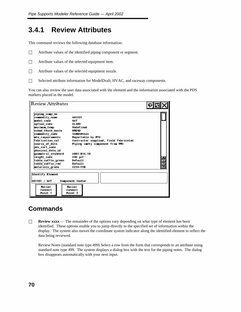
Pipe Supports Modeler Reference Guide — April 2002________________
3.4.1 Review Attributes
This command reviews the following database information:
Attribute values of the identified piping component or segment.
Attribute values of the selected equipment item.
Attribute values of the selected equipment nozzle.
Selected attribute information for ModelDraft, HVAC, and raceway components.
You can also review the user data associated with the element and the information associated with the PDSmarkers placed in the model.
Commands
Review xxxx — The remainder of the options vary depending on what type of element has beenidentified. These options enable you to jump directly to the specified set of information within thedisplay. The system also moves the coordinate system indicator along the identified element to reflect thedata being reviewed.
Review Notes (standard note type 499) Select a row from the form that corresponds to an attribute usingstandard note type 499. The system displays a dialog box with the text for the piping notes. The dialogbox disappears automatically with your next input.
70
3. Pip
e Su
pp
orts
Mo
deler
Review Attributes________________
Operating Sequence
1. Identify Element by snapping to the component, segment, equipment, nozzle or marker to be reviewed orplace a data point to locate a piping component.
2. Review Bolt Data. Review the following data for each bolted end of a piping component, pipe,instrument component, or equipment nozzle so that you can determine what angle a valve operator maybe rotated. This information is only available for a component with at least one bolted end.
the number of bolt holesthe bolt diameterthe bolt circle diameterthe acceptable rotation(360 degrees divided bythe number of bolt holes)
71

Pipe Supports Modeler Reference Guide — April 2002________________
3.4.2 Review Nozzle Data
This command is used to review the nozzle data associated with a selected piece of equipment. You can viewthe nozzle tag, nominal piping diameter, rating, table suffix, end prep, and piping materials class of the nozzles.For welded nozzles, the system displays the schedule/thickness rather than the pressure rating.
Identify Equipment by snapping to the equipment group to be reviewed.
Identify Equipment or Select Nozzle for Highlight. Select a nozzle from the form to highlight in themodel, or snap to the nozzle graphic to highlight the associated entry on the form.
72

3. Pip
e Su
pp
orts
Mo
deler
Review Report________________
3.4.3 Review Report
This option displays an existing report in the Review Report form. You can use the form controls to pagethrough the report. You can review any user-formatted reports including
Design Data (MTO) Reports
Design data reports are generated by the Report Manager.
Project Data Reports
Project data reports include those reports created through the Project Control Report command of theProject Administrator.
Reference Data Reports
Reference data reports include the piping spec reports created with the Piping Job Spec Manager and thequality control reports created with the Table Checker.
Commands
Select Another Report — Select this option to redisplay the list or reports and select another report toreview.
Review Report Details — Displays the Review Report Details form which provides a detailed list ofinformation for the report. It displays the revision description, the revised by, and the checked by reportmanagement data for the selected report.
73

Pipe Supports Modeler Reference Guide — April 2002________________ Substring Search — Searches the displayed file for the specified report number. If found, it displays theline containing the search string.
Two arrow buttons appear on either side of the substring entry to provide the Repeat Search option.These arrow buttons allow the user to search backward or forward. Each time you select the RepeatSearch option from the form, the system moves to the next occurrence of the search string progressingfrom top to bottom in the file. If the search reaches the end of the file without finding the search string,the message Search String Not Found appears. If you select Repeat Search again after the end of file,the system starts at the top of the file.
Filter List of Reports by Substring — Provides a field in which to enter a substring of the reportnumbers to display. Once you have entered the substring, only those reports which include the specifiedsubstring in the report number are displayed. A toggle is provided to display either the complete orpartial list of reports.
Restore Model View — Restores the active screen view to the view that was displayed before theReview Report option was selected. This option is available only after the MTO Diagnostics commandhas been selected.
MTO Diagnostics — Displays the MTO Diagnostics form which provides information on errorsencountered in generating the displayed report. Some of these errors are listed below:
Information on errors resulting from material description for bolts, nuts, or gaskets not being found.
Information on errors resulting from a gasket determined on the basis of data at one end of a bolted jointdiffering from the gasket determined on the basis of the data at the other end.
In this situation, the gasket’s thickness and the gasket’s commodity code for both ends of the bolted jointare displayed.
The system highlights all components related to a piping segment for errors that apply only to the pipingsegment (and not to its related components) so that the piping segment with the error can be easilyidentified.
When the nozzle associated with one end of piping segment cannot be located, the Coordinate SystemIndicator (CSI) is displayed at the end of the piping segment.
Operating Sequence
1. Select Report by selecting the report to be reviewed from the list. The system updates the form anddisplays the contents of the selected report file.
74

3. Pip
e Su
pp
orts
Mo
deler
Review Report________________
2. Report is Displayed for Review. Use the scroll bar and shift right/left arrows to review the contents ofthe report or select one of the options from the bottom of the form.
75

Pipe Supports Modeler Reference Guide — April 2002________________
3.4.4 Temporary Symbology
This command highlights elements based on specified search criteria or display temporary attribute labels. Youcan use the highlight option or change the color, line weight, or line style.
Commands
Active Color — Sets the active color by selecting one of the available colors on the Define Active Colorform.
Active Weight — Sets the active weight for use in highlighting elements.
Active Line Style — Sets or modifies the symbol line style.
Segment Search Criteria — Defines the segment search criteria to be used in modifying the displaysymbology.
Component Search Criteria — Defines the component search criteria to be used in modifying thedisplay symbology.
Display Only Labels — Places temporary attribute labels in a specified screen view.
This command only works for the active file.
Restore Permanent Symbology — Cancels the temporary symbology actions performed with theTemporary Symbology form.
76

3. Pip
e Su
pp
orts
Mo
deler
Temporary Symbology________________
Operating Sequence
1. Specify Search Criteria or Select Display Option. Select Segment Search Criteria or ComponentSearch Criteria to define the search criteria to be used in modifying the display symbology.
2. Select one of the symbology options ( Active Line Style ) to define the active symbology. (Theseoptions are only used when the toggle is set to Active Symbology.)
3. Select the Display Only Labels option to place temporary attribute labels in a specified screen view.
77
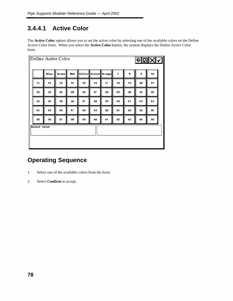
Pipe Supports Modeler Reference Guide — April 2002________________
3.4.4.1 Active Color
The Active Color option allows you to set the active color by selecting one of the available colors on the DefineActive Color form. When you select the Active Color button, the system displays the Define Active Colorform.
Operating Sequence
1. Select one of the available colors from the form.
2. Select Confirm to accept.
78

3. Pip
e Su
pp
orts
Mo
deler
Active Weight________________
3.4.4.2 Active Weight
The Active Weight option allows you to set the active line weight for use in highlighting elements. When youselect the Active Weight button, the system displays a slide bar.
Operating Sequence
You can modify the line weight by:
1. Modify the line weight by placing a data point at a specific point on the bar. The system moves the slidebutton to the data point displaying the new line weight.
— OR —
2. Modify the line weight by pressing <D> and holding the button as you move the mouse up or down thebar to the new line weight setting. As you move the slide button, the displayed line weight changes withrespect to the new button position.
79
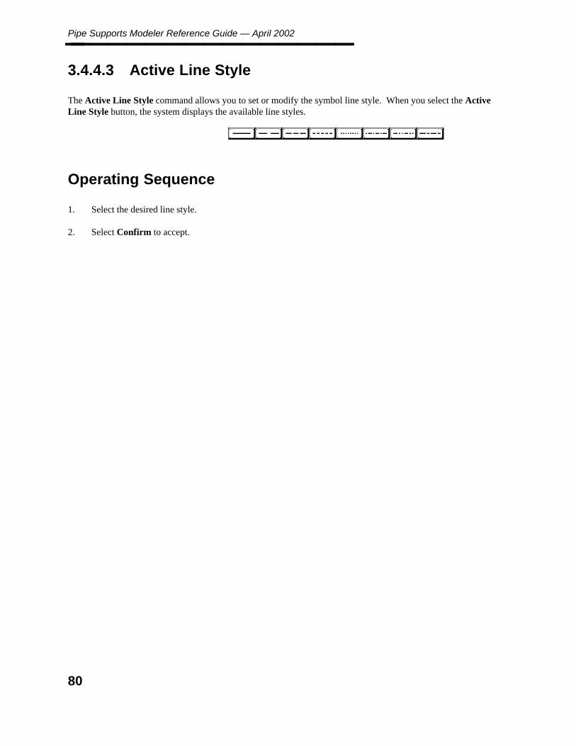
Pipe Supports Modeler Reference Guide — April 2002________________
3.4.4.3 Active Line Style
The Active Line Style command allows you to set or modify the symbol line style. When you select the ActiveLine Style button, the system displays the available line styles.
Operating Sequence
1. Select the desired line style.
2. Select Confirm to accept.
80
3. Pip
e Su
pp
orts
Mo
deler
Display Only Labels________________
3.4.4.4 Display Only Labels
The Display Only Labels command places temporary attribute labels in a specified screen view. The systemreviews the database attributes for the elements in the selected view and calculates the location, size, andcontents of the labels to be placed. A label is placed for each piping segment, tagged component, or symbol inthe view.
This command only works for the active file.
Before using this command
Set the screen view to fit the segments to be labeled. Depending on the view perspective and the spacingbetween line changes, labels may be placed on top of each other.
Operating Sequence
1. Select Label Type by selecting one of the Piping Segment, Tagged Component, or Symbol options toindicate the type of label to be displayed and place a data point to identify the screen view to display thetemporary label.
2. Select Confirm to accept.
81

Pipe Supports Modeler Reference Guide — April 2002________________
3.4.4.5 Restore Permanent Symbology
This command cancels the temporary symbology actions performed with the Temporary Symbology form. Itrestores the active symbology to the last saved (by File Design) parameters.
Operating Sequence
1. Specify Search Criteria or Select Display Option by selecting the Restore Permanent Symbologycommand.
2. Select Confirm to accept.
82
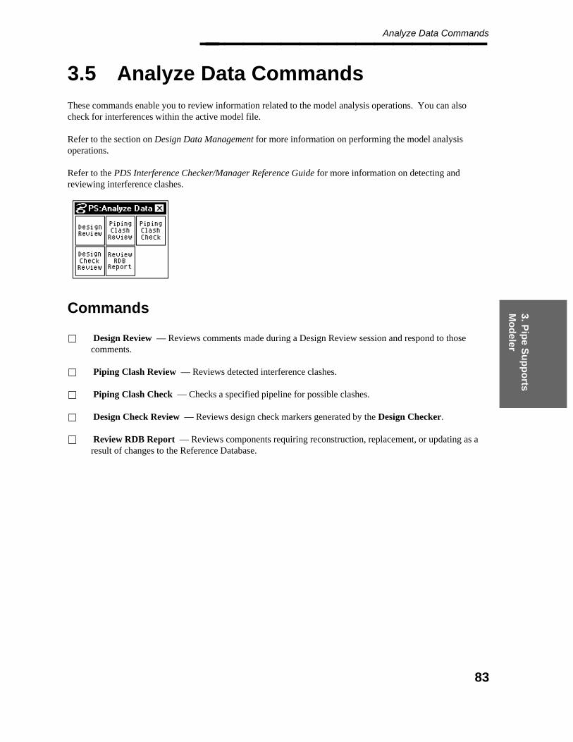
3. Pip
e Su
pp
orts
Mo
deler
Analyze Data Commands________________
3.5 Analyze Data Commands
These commands enable you to review information related to the model analysis operations. You can alsocheck for interferences within the active model file.
Refer to the section on Design Data Management for more information on performing the model analysisoperations.
Refer to the PDS Interference Checker/Manager Reference Guide for more information on detecting andreviewing interference clashes.
Commands
Design Review — Reviews comments made during a Design Review session and respond to thosecomments.
Piping Clash Review — Reviews detected interference clashes.
Piping Clash Check — Checks a specified pipeline for possible clashes.
Design Check Review — Reviews design check markers generated by the Design Checker.
Review RDB Report — Reviews components requiring reconstruction, replacement, or updating as aresult of changes to the Reference Database.
83
Pipe Supports Modeler Reference Guide — April 2002________________
3.5.1 Design Review
This command reviews the comments made during a Design Review session. It activates the Design Reviewform which displays information from the design review tag file.
You can review the comments by number, by a substring search, or by selecting the next or previous commentnumber. You can also attach a short explanation to any comment.
When using the next comment or previous comment option, this command filters out any comments that are notassociated with the active model. This filter is applied by comparing the physical location of the comment withthe volumetric range of the active model.
If a comment was made for a particular component during a Design Review session, that component ishighlighted in the specified screen view and the coordinate_axis is displayed at the tag point. If the componentis not found the system displays a message indicating the component was deleted.
You can store the tag file name, active comment number, and screen view to be updated by selecting FileDesign.
You can choose whether or not to filter the DesignReview tags to those that overlap the volume of the activepiping model. The default is to filter the DesignReview tags being reviewed by the volume.
For any DesignReview label that has been created without a leader line, the system determines whether or notthat tag is to be filtered from the review on the basis of the corresponding view volume. A rectangular viewvolume is computed as near a match to the tag’s perspective view as possible. If this rectangular volumeoverlaps the active piping model’s volume, the tag is displayed for review and possible comment.
The purpose of this change is a result of the fact that the tag’s view z location, as determined during theDesignReview session, may result in that tag’s 3D location not being within the volume of the active pipingmodel.
For any DesignReview tag that has been created with a leader line, the review of that tag will continue to bedetermined on the basis of whether the point of interest for that tag (the location of the component in themodel), falls within the volume of the active piping model.
84

3. Pip
e Su
pp
orts
Mo
deler
Design Review________________
Operating Sequence
1. Select the tag file to be reviewed.
2. Accept or Select Other Tag File
3. Select Confirm to review the comments in the selected tag file. The system activates the Design Reviewform.
85

Pipe Supports Modeler Reference Guide — April 2002________________
4. Select DesignReview Option.
5. Select the Comment Number field and type the number of the comment to review or use the PreviousComment - Next Comment option to display the comments sequentially based on their order in the tagfile.
You can also select the Substring field and type a word or phrase unique to the comment to review. Thesystem searches for the specified string in the comment and displays the associated comment.
You can change the tag file at any time by placing a data point over the Tag File field. Thesystem displays the list of tag files for selection.
86

3. Pip
e Su
pp
orts
Mo
deler
Piping Clash Review________________
3.5.2 Piping Clash Review
This option locates and review those interference clashes that have been reported for the active model. It can beused to help identify and correct interference clashes. This option operates similarly to the InterferenceManager option in the Interference Checker/Manager module.
As you review the clashes, the system highlights the two components involved in the clash.
Field Descriptions
Project Name — Displays the name of the active project.
Design Area — Displays the name of the active design area.
Responsible User — Displays the user’s initials for approved clashes when Access Control is active.The displayed user ID is loaded into the Clash Review History data table, PDtable_135, when the clash isapproved.
Clash Description — Displays the type of the active clash. (For example, hard versus hard is the typeshown in the documentation illustration.)
Date — Displays the date the checker was run. The information in this field is set with the Checker RunDates option in the Interference Checker/Manager module.
87

Pipe Supports Modeler Reference Guide — April 2002________________ Marker Number — Displays the number of the current clash. Select a marker number with the left andright arrows, select the field and type a marker number, or select the Keyin Marker Number option andtype a marker number.
Model / Area Name — Displays the names of the model files and the design area that have componentsinvolved in a clash.
Item A and Item B — Displays the model and area name of the clashing components. The systemaccesses the user-defined labels in the Label Description Library to create: the primary description, whichis displayed on the top line with a limit of 20 characters; and the secondary description, which isdisplayed on the bottom line and has a limit of 40 characters. These descriptions are defined with theClash Management Labels option on the Create Label Data form in the Reference Data Manager.
Comments: — Displays existing comments about the active clash.
Commands
Review Unapproved Clashes/ Review Approved Clashes — Limits active clash search to eitherunapproved or approved clashes.
Unapprove Clash — Select this option to unapprove the active approved clash.
Approve Real Clash — Select this option to approve the active clash as a real clash.
Approve False Clash — Select this option to approve the active clash as a false clash.
Plot Clashes — Select this option to immediately plot the clash being reviewed. The system generatestemporary plot files in the temp directory. This option uses the last-used queue or the default queue ifnothing has been plotted during the current session.
Select View — Select this option and identify the screen view to display the active clash.
Restore View — Select this option to restore the selected view to its original viewing parameters.
Highlight Clash — Select this option to highlight the active clash.
Keyin Marker Number — Select this option and type a marker number. The system updates thewindow coordinates about the clash in the selected view.
Detach Marker File / Attach Marker File — Set this toggle to the Detach Marker File setting todetach the marker file. Selecting the Attach Marker File setting refreshes the marker file, updating anymarkers that may have changed when the file was last modified.
88
3. Pip
e Su
pp
orts
Mo
deler
Piping Clash Review________________
Operating Sequence
1. Set the toggle to Review Unapproved Clashes or Review Approved Clashes to determine the type ofclashes to review.
2. Select the right arrow to scan the active model for the type of clashes selected in step 1.
The data for the next clash in the model will be presented in the appropriate fields.
3. Select any of the appropriate options to approve, unapprove, or plot the clashes as desired.
89
Pipe Supports Modeler Reference Guide — April 2002________________
3.5.3 Piping Clash Check
This command checks a pipeline or user-defined active groups for interferences immediately after completingthe line. It automatically creates interference envelopes in memory for any piping in the selected pipeline oractive group. It checks any attached reference models for which interference envelope files have been createdpreviously. It also reports any reference models for which interference envelopes have not been createdpreviously.
The results of this interactive clash checking is not maintained as a part of the Interference Management data.However, you can use the Piping Clash Review option to review the clashes detected by this command.
Construction tolerances and angular tolerances (tolerance for recognizing horizontal beams for determiningwhen piping is legitimately resting on steel) are considered during the interference checking process.
The sparse version of the structural model is used when creating interference envelopes. Model managementdata must be loaded for the sparse structural models through the Project Environment Manager. In order toreview clashes between piping and structural models, attach propagated structural models instead of sparsestructural models.
This command does not affect the interference envelopes created by the InterferenceManager’s Envelope Builder.
Commands
Select View — Identifies the screen view to display the active clash.
Restore View — Restores the active view(s) to the initial viewing parameters for the clash beingchecked.
Previous/Next Marker Number — Reviews the next/previous marker. The system updates the windowcoordinates about the clash in the selected view.
Operating Sequence
1. Identify Pipeline or Define Active Group — Snap to a segment or locate a component to identify thepipeline to be processed or use the Define Active Group command to identify define the items to beprocessed.
2. Select Confirm to Accept to Check Pipelineto process the identified pipeline or select Cancel (X) toreject the pipeline.
3. Identify another pipeline as outlined or select the Piping Clash Review option to review the detectedclashes.
90
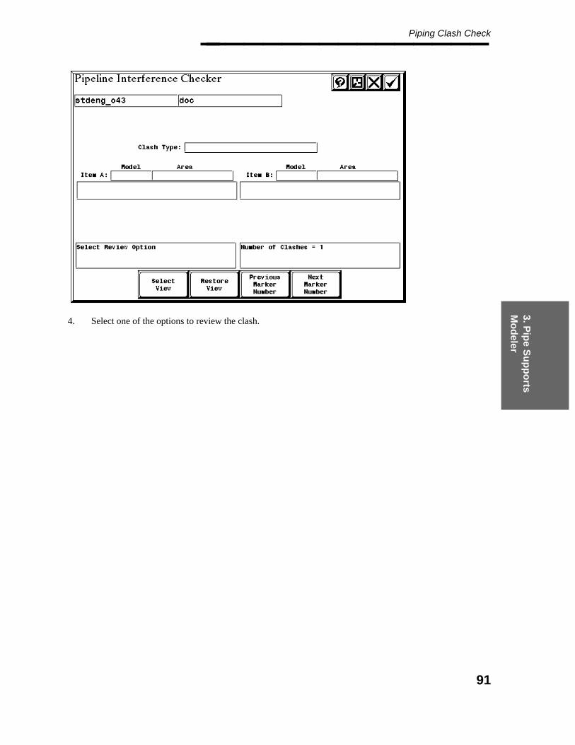
3. Pip
e Su
pp
orts
Mo
deler
Piping Clash Check________________
4. Select one of the options to review the clash.
91
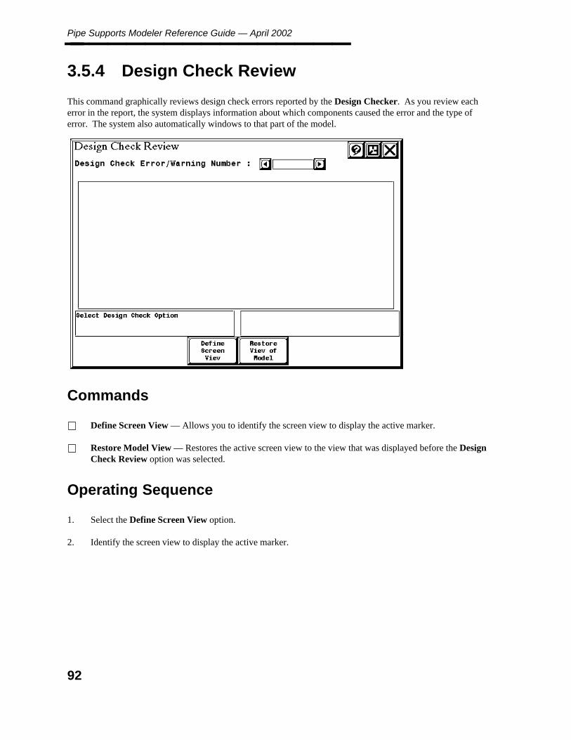
Pipe Supports Modeler Reference Guide — April 2002________________
3.5.4 Design Check Review
This command graphically reviews design check errors reported by the Design Checker. As you review eacherror in the report, the system displays information about which components caused the error and the type oferror. The system also automatically windows to that part of the model.
Commands
Define Screen View — Allows you to identify the screen view to display the active marker.
Restore Model View — Restores the active screen view to the view that was displayed before the DesignCheck Review option was selected.
Operating Sequence
1. Select the Define Screen View option.
2. Identify the screen view to display the active marker.
92
3. Pip
e Su
pp
orts
Mo
deler
Review RDB Report________________
3.5.5 Review RDB Report
This command reviews any component in the model requiring reconstruction, replacement, or update as a resultof changes to the Reference Database.
This command makes extensive use of data provided by the Reference Data Managers revision managementreports. Refer to the Reference Data Manager Reference Guide for more information regarding these reports.
You can review all pertinent information regarding the revision management reports for the Reference Databaseon the basis of the following error types.
a dimension table has been revised
Use the Reconstruct Component command with this component.
a weight table has been revised
Use the Update from Reference Database command with this component.
a discrepancy between the specification data in the model and that in the Reference Database
Use either the Reconstruct Component or the Update from Reference Database command with thiscomponent on the basis of which specification data has a discrepancy.
the specification data for a component in the model is missing from the Reference Database; it has beendeleted from the Reference Database
Delete this component and replace it with a different component or add this component to the ReferenceDatabase.
Although a component might be reported through more than one Reference Database Revision Managementreport as having data which is inconsistent with the Reference Database, the component will only be reportedfor review once by this command. Only the most severe discrepancy is reported using the following prioritizedlist.
1. The specification data for a component in the model is missing (has been deleted) from the ReferenceDatabase.
2. A dimension table has been revised.
3. A discrepancy between the specification data in the model and that in the Reference Database.
4. A weight table has been revised.
93
Pipe Supports Modeler Reference Guide — April 2002________________
Commands
Update Component from RDB– This option automatically revises the component in the model without exitingthe command. The system reconstructs the active component or updates its data from the reference database onthe basis of the type of error and the data involved. Once the component has been revised successfully, it willno longer be reported. The system also performs the following items where applicable:
Design Checker is automatically activated at the end of each end of any component or pipe that is beingreconstructed. Design Checker is not activated for non-geometric data that is updated on the basis of changesto the reference database.
If required as a result of a change to the fabrication category from the Reference Database, the weld type isupdated at each welded end of the component or pipe being reconstructed or updated. It is no longer necessaryto remember to correct the weld data that results from updating the fabrication category of a component or pipebeing reconstructed or updated at a welded joint when you have a Weld Type Table loaded.
If the Weld Type Table is loaded, the system defines the weld type using the Weld Type Table. A Weld TypeTable is delivered in win32app\ingr\pddata\sample\data called weld.tbl. A sample of the data that it contains isshown below.
Table_Data_Definition ’Weld_Type_Table’
No_Inputs 2 No_Outputs 1Units= INT, INT, INT
! Fab Cat Fab Cat Weld Type
1 1 11 5 211 7 211 15 211 16 211 17 211 25 211 27 21
If a Weld Type Table has not been defined for the project, the weld type is revised to the default weld typevalue, ’shop weld’ (11).
If you set the toggle on the Revise Weld Type form to Respect Weld Type by User, the weld type is notrevised for either the welded end of the component or pipe being reconstructed or updated or the correspondingwelded end of the other component. Also, the weld type is not revised when the mating welded end is not in theactive piping model, since you do not have write access to reference models.
When the system defines the weld type, the following considerations are made:
— The system uses the Weld Type Table to determine the weld type on the basis of the fabrication category forthe component or pipe being reconstructed or updated and the other component at the welded joint.
— If the weld type of the other component at the welded joint differs from the one determined by the project’sWeld Type Table, the weld type of the applicable end of that component is updated to the same weld type asthat of the end of the component or pipe being reconstructed or updated on the basis of the Weld TypeTable.
94

3. Pip
e Su
pp
orts
Mo
deler
Review RDB Report________________ The Report Date field represents the most recent date for which a discrepancy was reported for that componentinvolving the component’s data in the model and the corresponding reference data. This date will notnecessarily be the date the specific discrepancy was reported or the date of the most recent revision managementreport.
The Discrepancy field indicates the type of error. For all components, regardless of the type of discrepancyreported, the system indicates if the component requires reconstruction as a result of changes to piping segmentdata in the model, such as piping materials class or nominal piping diameter. This might save you fromneedlessly updating the component’s data from the Reference Database when other revision managementfacilities would indicate that reconstruction is required. For example, a component might be reported as onlyrequiring updating as a result of revisions to the Reference Database, whereas that same component mightrequire reconstruction as a result of changes in the model.
You can select the right arrow to display the next discrepancy. The components being reviewed are sorted byline id.
If you must exit this command to make related revisions in the model or for any other reason and then re-enterthis command for analysis purposes, the next component in the revision management is displayed automatically.
95

Pipe Supports Modeler Reference Guide — April 2002________________
3.6 View Commands
These commands provide view manipulations. All of these commands result in modifying what is seen in theselected views. These commands only manipulate the view of the model, but do not manipulate the actualmodel.
For further information see the View Commands section of the Piping Design Graphics (PD_Design) document(DEA5029A0).
96

3. Pip
e Su
pp
orts
Mo
deler
File Commands________________
3.7 File Commands
These commands provide file manipulations. These commands allow you to plot and diagnose problems indesign files. They also allow you to define the active options for the file and what reference models are attachedand displayed.
For further information see the File Commands section of the Piping Design Graphics (PD_Design) document(DEA5029A0).
97

Pipe Supports Modeler Reference Guide — April 2002________________
3.7.1 File Options
3.7.1.1 Return to Piping
This command allows you to switch from the Pipe Supports Modeler back to the Piping Designer if you enteredthe Pipe Supports Modeler using the Piping Designer Switch to Pipe Support command.
3.7.1.2 Switch to FWP
This command activates the Switch to Frameworks Model form that allows you to switch to the FrameworksPlus (FWP) environment so that you can modify structural models that are referenced from the active pipesupports model.
Select the desired Frameworks Plus model, then confirm the form to enter the FWP environment. When you arefinished using the FWP environment, save the FWP model, and exit the FWP environment.
98

3. Pip
e Su
pp
orts
Mo
deler
File Options________________ If Access Control is being used on the active project, this command does verify that you have
access to modify FWP data before allowing you to do so.
For further information on the other File Options commands, see the File Commands section of the PipingDesign Graphics (PD_Design) document (DEA5029A0).
99
Pipe Supports Modeler Reference Guide — April 2002________________
3.8 Element Commands
The Element pull-down provides the Analyze command.
For further information see the Element Commands section of the Piping Design Graphics (PD_Design)document (DEA5029A0).
100
3. Pip
e Su
pp
orts
Mo
deler
Settings Command________________
3.9 Settings Command
The Settings commands provide the ability to modify rendering, fonts and colors used during a graphicssession.
For further information see the Setting Commands section of the Piping Design Graphics (PD_Design)document (DEA5029A0).
101
Pipe Supports Modeler Reference Guide — April 2002________________
3.10 User Commands
The User commands provide access to PDS help and to the user preferences and button assignments that arespecific to your system.
For further information see the User Commands section of the Piping Design Graphics (PD_Design) document(DEA5029A0).
102

3. Pip
e Su
pp
orts
Mo
deler
Applications Command________________
3.11 Applications Command
The Applications command provides information regarding the applications currently running associated withPDS.
103

Pipe Supports Modeler Reference Guide — April 2002________________
104
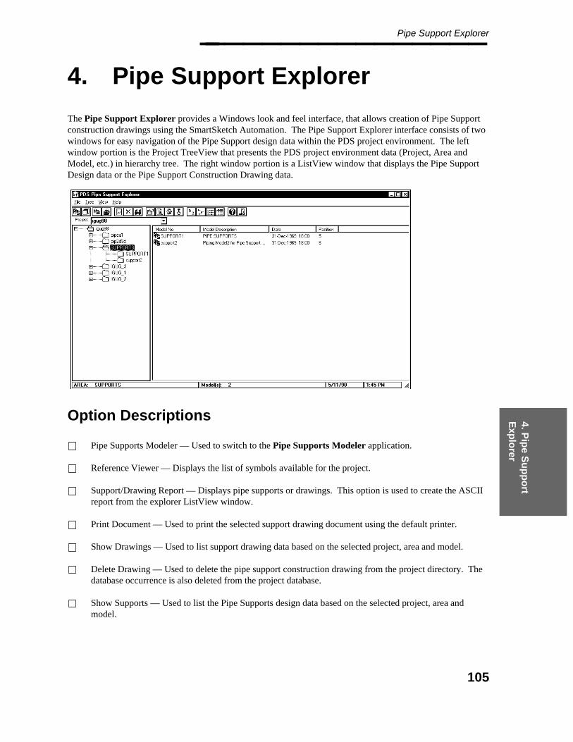
4. Pip
e Su
pp
ort
Exp
lorer
Pipe Support Explorer________________
4. Pipe Support Explorer
The Pipe Support Explorer provides a Windows look and feel interface, that allows creation of Pipe Supportconstruction drawings using the SmartSketch Automation. The Pipe Support Explorer interface consists of twowindows for easy navigation of the Pipe Support design data within the PDS project environment. The leftwindow portion is the Project TreeView that presents the PDS project environment data (Project, Area andModel, etc.) in hierarchy tree. The right window portion is a ListView window that displays the Pipe SupportDesign data or the Pipe Support Construction Drawing data.
Option Descriptions
Pipe Supports Modeler — Used to switch to the Pipe Supports Modeler application.
Reference Viewer — Displays the list of symbols available for the project.
Support/Drawing Report — Displays pipe supports or drawings. This option is used to create the ASCIIreport from the explorer ListView window.
Print Document — Used to print the selected support drawing document using the default printer.
Show Drawings — Used to list support drawing data based on the selected project, area and model.
Delete Drawing — Used to delete the pipe support construction drawing from the project directory. Thedatabase occurrence is also deleted from the project database.
Show Supports — Used to list the Pipe Supports design data based on the selected project, area andmodel.
105

Pipe Supports Modeler Reference Guide — April 2002________________ Properties — Provides attribute and value information associated with the selected project, model,drawing or pipe support.
View Drawing — Used to a view a drawing using SmartSketch viewer.
Generate Drawing — Used to generate a new SmartSketch automation.
Large Icon View — Used to display project, model, drawing or pipe support icons in large format.
Small Icon View — Used to display project, model, drawing or pipe support icons in small format.
List View — Used to display project, model, drawing or pipe support icons in small icon format.
Details View — Used to display project, model, drawing or pipe support icons in small icon format withattribute details.
Help — Used to display on-line information about pipe support commands.
Exit — Used to exit the PDS Pipe Support Explorer software.
Operating Sequence
1. Select the Pipe Support Explorer icon.
The Pipe Support Explorer menu is displayed.
2. Select a project by double-clicking on a project icon or select from the Select Project pull-down list.
The project is attached and initialized.
106

4. Pip
e Su
pp
ort
Exp
lorer
Pipe Supports Modeler________________
4.1 Pipe Supports Modeler
The Pipe Supports Modeler option is used to switch to the Pipe Supports Modeler application.
See Pipe Support Place Commands, page 37 Pipe Supports Place Commands for moreinformation about this option.
Operating Sequence
1. Select the model from the Pipe Support Explorer window TreeView.
2. Select the Pipe Supports Modeler icon from the PDS Pipe Support Explorer menu.
The information dialog box is displayed with the message: "Enter PDS Pipe Support GraphicsEnvironment, Model: XXX".
3. Select Yes to activate the PDS Pipe Support Modeler module.
— OR —
Select No to return to the Pipe Support Explorer window environment.
107

Pipe Supports Modeler Reference Guide — April 2002________________
4.2 Reference Viewer
The Reference Viewer option displays the list of symbols available for the project. The Reference Viewerwindow contains two views. The left window displays the symbols available for the selected project. The rightwindow displays a graphic view of the selected symbol’s graphic presentation.
Operating Sequence
1. Select the Reference Viewer option.
Select the Reference Viewer icon from the PDS Pipe Support Explorer menu.
The Reference Viewer displays the two windows with available symbols and symbol graphicpresentation.
2. Select the symbol name from the left window ListView.
The selected symbol’s graphic presentation displays on the left window pane.
108
4. Pip
e Su
pp
ort
Exp
lorer
Support/Drawing Report________________
4.3 Support/Drawing Report
The Support/Drawing Report option is used to create the ASCII reports for selected supports or drawings.The generated report contains the same information as the Details View for the selected items.
Operating Sequence
1. Select the Show Drawings or Show Supports option.
2. Select one or more items to be included on the report.
You can use the Shift and Control keys to select multiple items.
3. Display the ListView window and select the items to be included in the report.
The selected items can be sorted by selecting the View column.
4. Select the Support/Drawing Report icon from the PDS Pipe Support Explorer menu.
The Save File dialog box is displayed.
5. Specify the Saved File Name and Directory location.
109
Pipe Supports Modeler Reference Guide — April 2002________________
4.4 Print Document
The Print Document option is used to print the selected SmartSketch Drawing document.
Operating Sequence
1. Select the Show Drawings or Show Supports option.
2. Select one or more items to be included on the report.
You can use the Shift and Control keys to select multiple items.
3. Select the Print Drawing option.
Select the Print Drawing icon from the PDS Pipe Support Explorer menu.
The selected drawings print on the default printer.
110
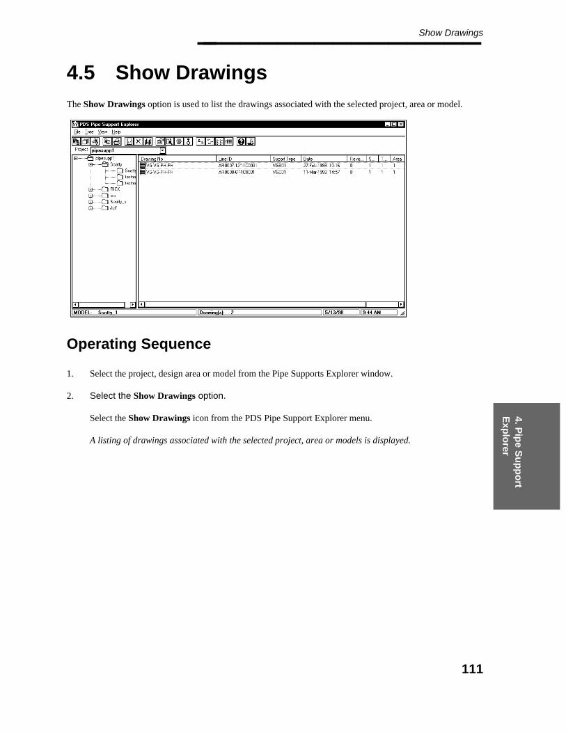
4. Pip
e Su
pp
ort
Exp
lorer
Show Drawings________________
4.5 Show Drawings
The Show Drawings option is used to list the drawings associated with the selected project, area or model.
Operating Sequence
1. Select the project, design area or model from the Pipe Supports Explorer window.
2. Select the Show Drawings option.
Select the Show Drawings icon from the PDS Pipe Support Explorer menu.
A listing of drawings associated with the selected project, area or models is displayed.
111

Pipe Supports Modeler Reference Guide — April 2002________________
4.6 Delete Drawing
The Delete Drawing option is used to delete a pipe support drawing from within the Pipe Support Explorermodule.
Operating Sequence
1. Select the drawing to be deleted.
Select the drawing number to be deleted from the Drawing ListView window.
The selected drawing number is highlighted.
2. Select the Delete Drawing option.
Select the Delete Drawing icon from the PDS Pipe Support Explorer menu.
The Confirmation dialog window is displayed to verify delete.
Any drawing with the "Locked" or "Released" status cannot be deleted.
3. Select Confirm.
Select Confirm to delete the selected drawing.
The system deletes the SmartSketch drawing file and removes the drawing record from PDtable_170.
112

4. Pip
e Su
pp
ort
Exp
lorer
Show Supports________________
4.7 Show Supports
The Show Supports option is used to display a listing of supports for a selected Area or Model. The PipeSupport design data is listed by Tag Number with information regarding material index, mark number, modelcode, date, gang, group, area and model included.
Operating Sequence
1. Select the project, area or model for the supports to be displayed.
The selected project, area or model is highlighted.
2. Select the Show Supports option.
Select the Show Supports icon from the PDS Pipe Support Explorer menu.
The message is displayed to indicate data is being loaded. A listing of pipe supports is displayed by TagNumber.
113
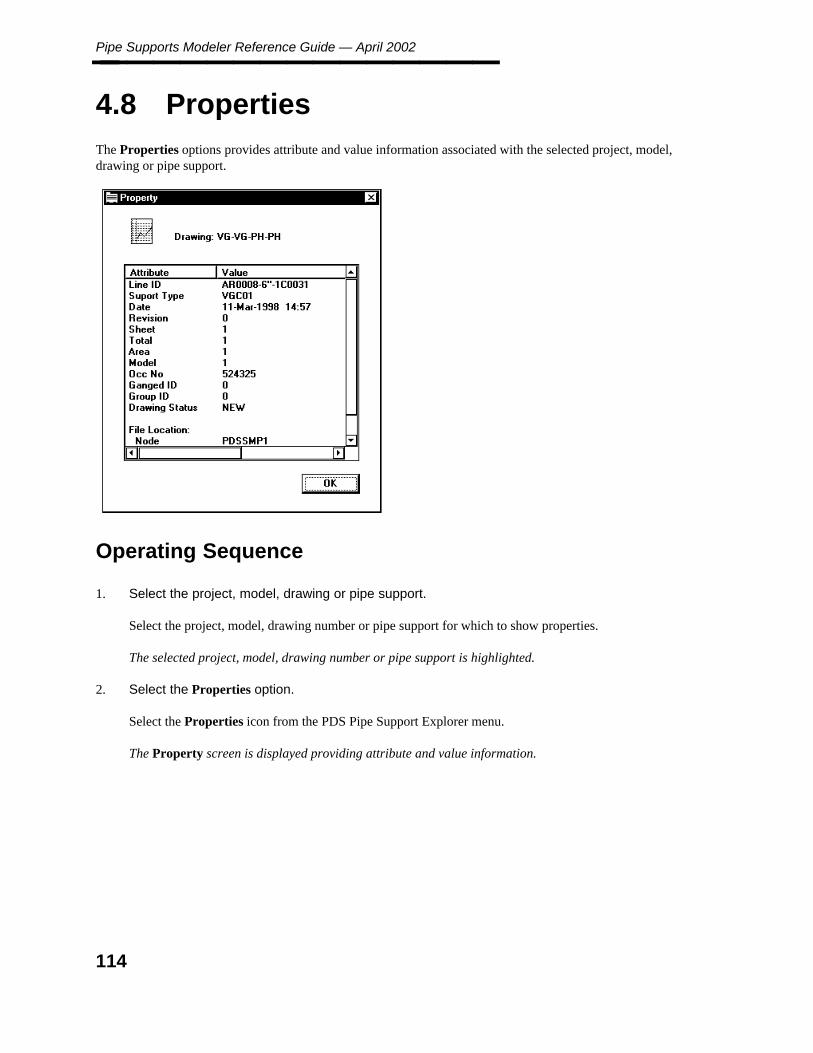
Pipe Supports Modeler Reference Guide — April 2002________________
4.8 Properties
The Properties options provides attribute and value information associated with the selected project, model,drawing or pipe support.
Operating Sequence
1. Select the project, model, drawing or pipe support.
Select the project, model, drawing number or pipe support for which to show properties.
The selected project, model, drawing number or pipe support is highlighted.
2. Select the Properties option.
Select the Properties icon from the PDS Pipe Support Explorer menu.
The Property screen is displayed providing attribute and value information.
114

4. Pip
e Su
pp
ort
Exp
lorer
View Drawing________________
4.9 View Drawing
The View Drawing option is used to view a drawing using ImagView.
Operating Sequence
1. Select the drawing to view.
Select the drawing number to view.
The selected drawing number is highlighted.
2. Select the View Drawing option.
Select the View Drawing icon from the PDS Pipe Support Explorer menu.
The ImagView screen is displayed with the selected drawing number highlighted.
3. Select drawing.
Double-click the selected drawing number.
The ImagView screen displays the selected drawing.
115
Pipe Supports Modeler Reference Guide — April 2002________________
4.10 Generate Drawing
The Generate Drawing option is used to generate a new SmartSketch drawing for a pipe support.
SmartSketch must be loaded to use this option.
Pipe Supports Explorer incorporates the functionality of SmartSketch as the tool to generate drawings toproduce a standard support detailed drawing.
Operating Sequence
1. Select the Show Supports option.>
Select the Show Supports icon from the PDS Pipe Support Explorer menu.
The message is displayed to indicate data is being loaded. A listing of pipe supports is displayed by TagNumber.
Select Item
Select the Pipe Support Item from the Support Data window.
2. Select the Generate Drawing option.
Select the Generate Drawing icon.
The drawing is generated using SmartSketch.
116
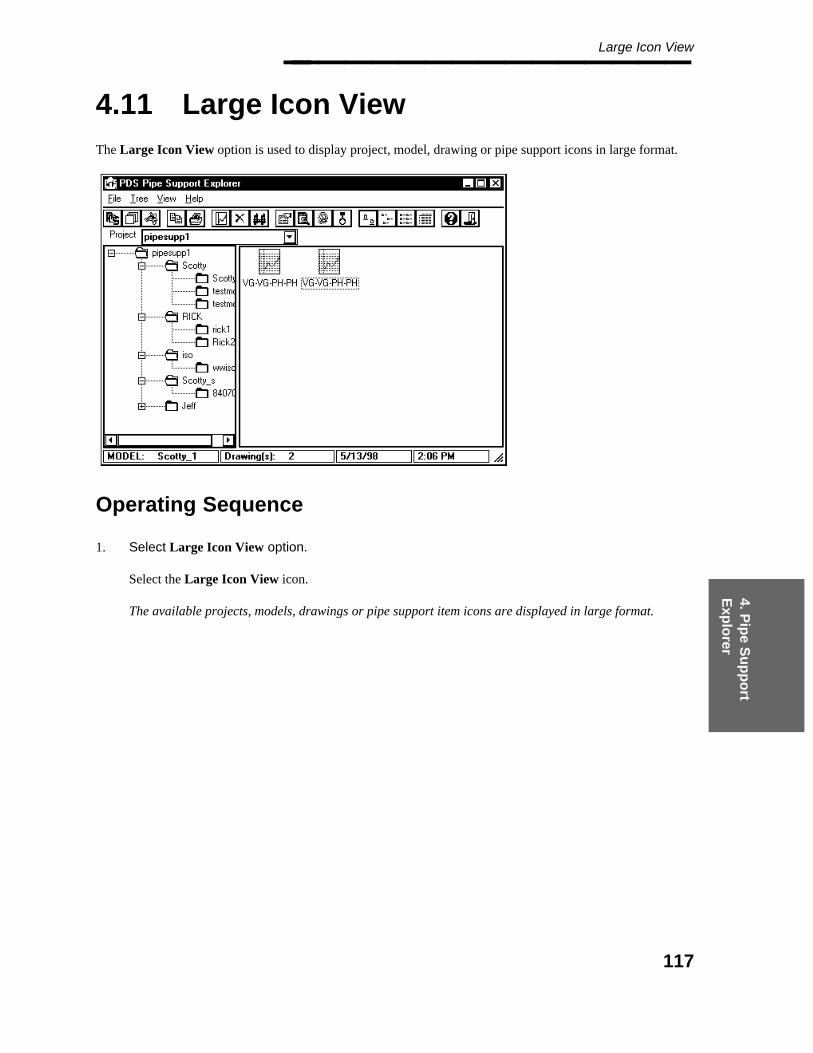
4. Pip
e Su
pp
ort
Exp
lorer
Large Icon View________________
4.11 Large Icon View
The Large Icon View option is used to display project, model, drawing or pipe support icons in large format.
Operating Sequence
1. Select Large Icon View option.
Select the Large Icon View icon.
The available projects, models, drawings or pipe support item icons are displayed in large format.
117
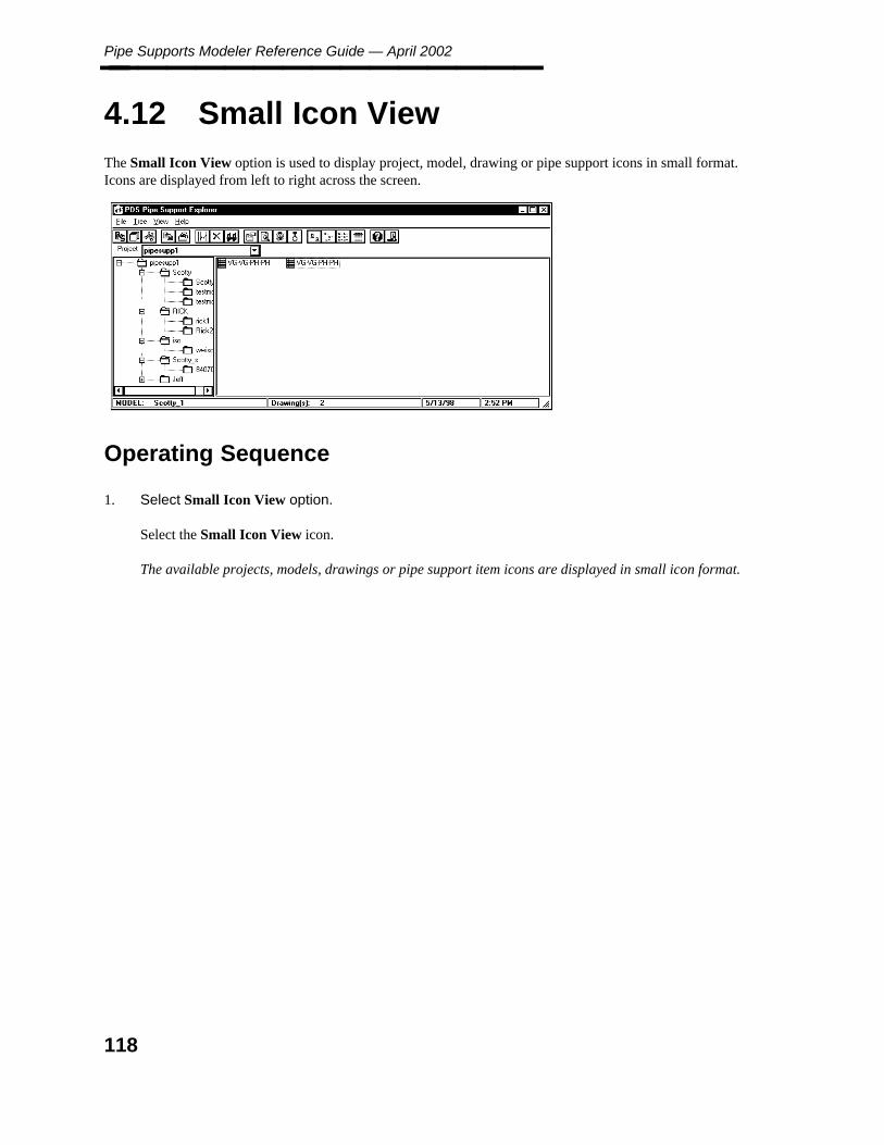
Pipe Supports Modeler Reference Guide — April 2002________________
4.12 Small Icon View
The Small Icon View option is used to display project, model, drawing or pipe support icons in small format.Icons are displayed from left to right across the screen.
Operating Sequence
1. Select Small Icon View option.
Select the Small Icon View icon.
The available projects, models, drawings or pipe support item icons are displayed in small icon format.
118

4. Pip
e Su
pp
ort
Exp
lorer
List View________________
4.13 List View
The List View option is used to display project, model, drawing or pipe support icons in small icon format.Items are displayed in vertical columns.
Operating Sequence
1. Select List View option.
Select the List View icon.
The available projects, models, drawings or pipe support item icons are displayed in small icon format invertical columns.
119

Pipe Supports Modeler Reference Guide — April 2002________________
4.14 Details View
The Details View option is used to display project, model, drawing or pipe support icons in small icon formatwith property attribute details. Items are displayed in vertical columns.
Operating Sequence
1. Select Details View option.
Select the Details View icon.
The available projects, models, drawings or pipe support item icons are displayed in small icon formatwith property information in vertical columns.
120
4. Pip
e Su
pp
ort
Exp
lorer
Help________________
4.15 Help
The Help option is used to display on-line information about pipe support commands.
Operating Sequence
1. Select Help option.
Select the Help icon.
The on-line help information for pipe supports is displayed.
121

Pipe Supports Modeler Reference Guide — April 2002________________
4.16 Exit
The Exit option is used to exit the PDS Pipe Support Explorer software.
Operating Sequence
1. Select Exit option.
Select the Exit icon.
The PDS Pipe Support Explorer software is closed.
122

5. Sm
artSketch
S
ymb
ols
SmartSketch Symbol Introduction________________
5. SmartSketch SymbolIntroduction
The SmartSketch symbol is a collection of entities (graphics such as line, arc, or text, and the label property)that forms a single object and can be used multiple times. The concept of the SmartSketch symbol is looselyequivalent with Microstation cells and AutoCAD blocks. The symbol is a file with a default filename extensionof *.sym.
Pipe Support Modeler delivers a set of seed symbols and an SmartSketch seed document to be used by theSmartSketch Drawing automation. The SmartSketch file dwgseed.igr defines the support drawing defaultborder (the SmartSketch background sheet) and default sheet settings. Refer to SmartSketch Help topic Set UpA Drawing Sheet for more information.
The symbols with filenames starting with dwg***.sym are the support drawing default layout symbols to beused for the drawing key plan, support graphic presentation, support MTO, support data, and drawingtitle block. These delivered symbol files include:
dwgaplan.symdwgarrow.symdwgkey01.symdwgkey02.symdwgkey03.symdwgkey04.symdwgMto1.symdwgMto2.symdwgseed.igrdwgTitleBlock.sym
These symbols contain symbol label properties. The symbol label property is an editable attribute set. Whenthe symbol is inserted into a document, the symbol occurrence inherits the properties defined by these symbolattribute sets. Pipe Support Modeler automation uses these label properties to place the Support MTO data topre-defined text locations.
For each standard support defined in the PDS project as defined in attribute 7 of pdtable_242, PipeSupport Modeler delivers a corresponding support graphic representation symbol file. The sym filenameshould be the same as the attribute 7 value.
123

Pipe Supports Modeler Reference Guide — April 2002________________
124
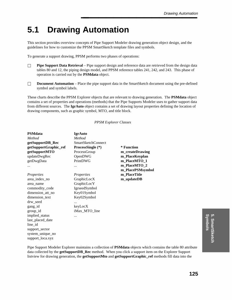
5. Sm
artSketch
S
ymb
ols
Drawing Automation________________
5.1 Drawing Automation
This section provides overview concepts of Pipe Support Modeler drawing generation object design, and theguidelines for how to customize the PPSM SmartSketch template files and symbols.
To generate a support drawing, PPSM performs two phases of operations:
Pipe Support Data Retrieval – Pipe support design and reference data are retrieved from the design datatables 80 and 12, the piping design model, and PPSM reference tables 241, 242, and 243. This phase ofoperation is carried out by the PSMdata object.
Document Automation – Place the pipe support data in the SmartSketch document using the pre-definedsymbol and symbol labels.
These charts describe the PPSM Explorer objects that are relevant to drawing generation. The PSMdata objectcontains a set of properties and operations (methods) that the Pipe Supports Modeler uses to gather support datafrom different sources. The IgrAuto object contains a set of drawing layout properties defining the location ofdrawing components, such as graphic symbol, MTO, and title block.
PPSM Explorer Classes
PSMdata IgrAutoMethod MethodgetSupportDB_Rec SmartSketchConnectgetSupportGraphic_ref ProcessSingle (*) * FunctiongetSupportMTO ProcessGroup m_createDrawingupdateDwgRec OpenDWG m_PlaceKeyplangetDwgData PrintDWG m_PlaceMTO_1... ... m_PlaceMTO_2
m_PlacePSMsymbolProperties Properties m_PlaceTitlearea_index_no GraphicLocX m_updateDBarea_name GraphicLocYcommodity_code IgrseedSymboldimension_att_no Key01Symboldimension_text Key02Symboldrw_seed ...gang_id keyLocXgroup_id iMax_MTO_lineimplied_status ...last_placed_dateline_idsupport_sectorsystem_unique_nosupport_loca.xyz
Pipe Support Modeler Explorer maintains a collection of PSMdata objects which contains the table 80 attributedata collected by the getSupportDB_Rec method. When you click a support item on the Explorer Supportlistview for drawing generation, the getSupportMto and getSupportGraphic_ref methods fill data into the
125

Pipe Supports Modeler Reference Guide — April 2002________________ PSMdata object matching the selected support listview tag. The getSupportMto method gets the collection ofMTO records from table 243, and the getSupportGraphic_ref method gathers all relevant support data such asthe support line_id, location coordinate, key plan data, and drawing symbol seed information from tables 12 and242, and the piping design model. Once the PSMdata object has all the necessary data, the SmartSketchAutomation object IgrAuto carries out the drawing generation automation tasks.
126

5. Sm
artSketch
S
ymb
ols
PPSM Symbols________________
5.1.1 PPSM Symbols
There are two types of symbol delivered with the Pipe Support Modeler. The first type of symbol is thestandard support graphic symbol, such as CCA.sym and CCB.sym. The second type of symbol is thedrawing layout symbol. The drawing layout symbols with the file name prefix dwg are used to define thedrawing text format of each drawing text component, while the drawing layout symbols with the file nameprefix loc are used to define the drawing item location on the support drawing.
The Pipe Support Modeler symbols SmartSketch documents with the .SYM file name extension. Thesesymbols contain descriptive information called Symbol Labels. Symbol Labels are used to place support textdata with pre-defined formats at pre-defined locations. The Symbol Label Property Names are constant textstrings used by the software. The Symbol Label Value can be set to null or can contain a Label FormatString. The Label Format String fields are delimited by dashes (-), and can be composed of text and valuesfrom various locations. For example,
242,2 specifies format data from attribute 2 of table 242.31 specifies format data using project label description
library label number 31."XXX" specifies a text string enclosed in quotation marks.
The following table lists valid label names and delivered samples of format label values.
dwgTitleBlock.sym dwgMto1.symname value name value
drw_no 241,2-2131-"PH"-2130 1 NULLrevision 0 2 NULLsheet_total 0sheet_no 0 80 NULLdata_field date
dwgMto2.sym dwgkey0x.symname value name value
tag NULL bubble1 NULLtype 241,2 bubble2 NULLarea NULL dim1 NULLlineid NULL dim2 NULLlocx NULLlocy NULLlocz NULLuser1 2132
For more information on how to create and modify symbol labels, please refer to the SmartSketch online helpsections Create a Symbol Label, Edit Symbol Properties, and Symbols Overview.
127
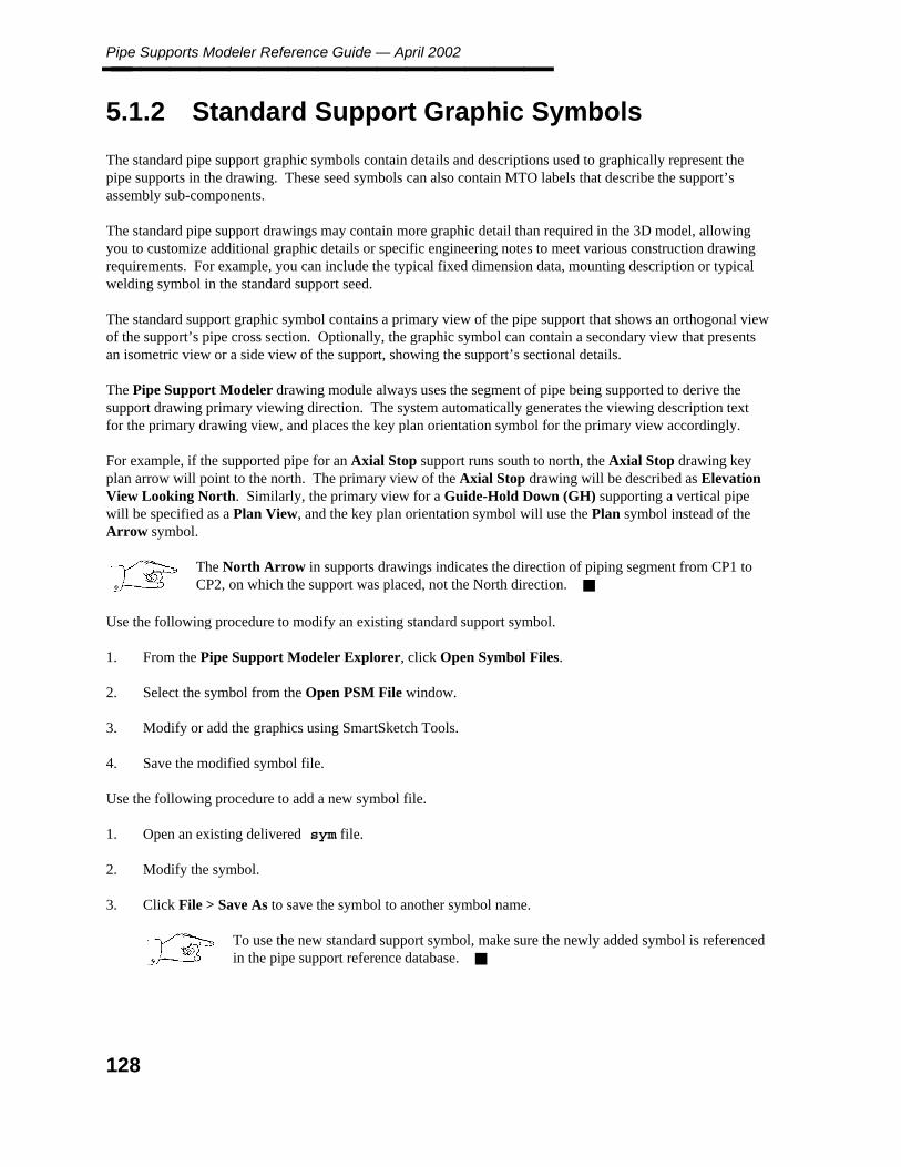
Pipe Supports Modeler Reference Guide — April 2002________________
5.1.2 Standard Support Graphic Symbols
The standard pipe support graphic symbols contain details and descriptions used to graphically represent thepipe supports in the drawing. These seed symbols can also contain MTO labels that describe the support’sassembly sub-components.
The standard pipe support drawings may contain more graphic detail than required in the 3D model, allowingyou to customize additional graphic details or specific engineering notes to meet various construction drawingrequirements. For example, you can include the typical fixed dimension data, mounting description or typicalwelding symbol in the standard support seed.
The standard support graphic symbol contains a primary view of the pipe support that shows an orthogonal viewof the support’s pipe cross section. Optionally, the graphic symbol can contain a secondary view that presentsan isometric view or a side view of the support, showing the support’s sectional details.
The Pipe Support Modeler drawing module always uses the segment of pipe being supported to derive thesupport drawing primary viewing direction. The system automatically generates the viewing description textfor the primary drawing view, and places the key plan orientation symbol for the primary view accordingly.
For example, if the supported pipe for an Axial Stop support runs south to north, the Axial Stop drawing keyplan arrow will point to the north. The primary view of the Axial Stop drawing will be described as ElevationView Looking North. Similarly, the primary view for a Guide-Hold Down (GH) supporting a vertical pipewill be specified as a Plan View, and the key plan orientation symbol will use the Plan symbol instead of theArrow symbol.
The North Arrow in supports drawings indicates the direction of piping segment from CP1 toCP2, on which the support was placed, not the North direction.
Use the following procedure to modify an existing standard support symbol.
1. From the Pipe Support Modeler Explorer, click Open Symbol Files.
2. Select the symbol from the Open PSM File window.
3. Modify or add the graphics using SmartSketch Tools.
4. Save the modified symbol file.
Use the following procedure to add a new symbol file.
1. Open an existing delivered sym file.
2. Modify the symbol.
3. Click File > Save As to save the symbol to another symbol name.
To use the new standard support symbol, make sure the newly added symbol is referencedin the pipe support reference database.
128

5. Sm
artSketch
S
ymb
ols
Drawing Layout Symbols________________
5.1.3 Drawing Layout Symbols
Drawing layout symbol file names are prefixed with dwg. These files should be copied to the PipeSupport Drawing Symbol directory defined in the Reference Data Manager.
Pipe Support Modeler delivers the following drawing layout templates and symbols:
dwgTitleBlock.symdwgMto1.symdwgMto2.symdwgaplan.symdwgarrow.symdwgkey01.symdwgkey02.symdwgkey03.symdwgkey04.sym
The symbols delivered with Pipe Support Modeler can be modified to meet your drawing requirements. Youcan change the seed document border or title block layout simply by modifying the delivered symbol files in theproject Drawing Support Symbol directory.
129

Pipe Supports Modeler Reference Guide — April 2002________________
5.1.4 Drawing Title Block (dwgTitleBLock.sym)
The title block drawing number is a formatted text label that can be combined using formatted labels from thePiping Segment Data and Pipe Support Data.
For example, if you define a piping segment label 2121 that consists of the unit_number andfluid_code attributes, and a pipe support data label 2130 that consists of the pipe_support_noattribute, a drawing number 9-PH-FW-0001 could be generated where 9 is the unit_number value, FWis the fluid_code value, and 0001 is the pipe_support_no value.
130

5. Sm
artSketch
S
ymb
ols
Support Drawing Formatted Text________________
5.1.5 Support Drawing Formatted Text
The formatted label texts such as the pipe line number, support mark number and MTO data can be placed indrawing at user-defined locations. The attribute data from the following database tables can be used to createrequired text information and MTO for the support drawing.
By using Symbol Label Format String 111,1 or 242,2 to place attribute data from following tables:
Table 111 Project Engineering Discipline dataTable 112 Project Design Area dataTable 113 Project Model DataTable 240 Reference Pipe Support Material Description data
The Label Description Libabry label created from tables 12 and 80 can be formatted and placed into the PPSMsupport document, by simply specifying the label number in the template symbol label format text string. Forexample, 242,2-2130 will format a label using table 241 attribute 2 and label number 2130.
Table 12 Design Piping Segment DataTable 80 Design Pipe Support data
The delivered Label Description library provides the following sample Report Label numbers to illustrate thelabel description usage in conjunction with the PPSM symbol label format.
2130 PPSM Support Tag No2131 PPSM Line ID2132 PPSM mark number
131
Pipe Supports Modeler Reference Guide — April 2002________________
5.1.6 Support Location Key Plan
PPSM will determine the closest column or grid line to the support component and place the support key planwith its dimension referenced to the column grid automatically. The column/grid line balloon and supportidentifier symbols are user-definable.
dwgaplan.symdwgarrow.symdwgkey01.symdwgkey02.symdwgkey03.symdwgkey04.sym
132

5. Sm
artSketch
S
ymb
ols
Drawing Layout Customization________________
5.1.7 Drawing Layout Customization
The seed template file dwgseed.igr defines the layout properties of the drawing, such as the drawing borderbackground sheet, the locations of the MTO text box, title blocks, support graphic representation and key planin the drawing.
Pipe support construction drawing layouts can be customized to suit your drawing requirements. The PPSMdelivered drawing seed file dwgseed.igr provides two sample drawing layouts: A size Tall (8.5 in x11 in) and an A size Wide (11in x 8.5in) format. Each drawing layout has its Background Sheet samplenamed A4 Vertical and A4 Horizontalrespectively. The Background Sheet contains sampledrawing border layouts that can modified.
Use the following procedure to change the project seed drawing layout.
1. From the Pipe Support Modeler Explorer, click Open Symbol Files.
2. Select dwgseed.igr on the Open PSM File window.
3. Click File > Sheet Setup.
4. On the Sheet Setup dialog box, click the Background tab.
5. Select a new background sheet from the list.
You can select View > Background Sheet to switch to the Background sheet, to add and modify theBackground Sheet graphics.
PPSM uses reference information in the following location symbol files to place pipe support drawing data suchas support graphic symbol, MTO, and title block text to user-defined locations in the drawing.
locGra.sym Drawing layout location for support graphic symbollocKey.sym Drawing layout location for support key planlocMto1.sym Drawing layout location for MTO textlocMto2.sym Drawing layout location for misc. MTO textlocTitle.sym Drawing layout for drawing title block text
Each of these symbols contains a rectangle that defines the boundary of the drawing element to be placed intothe drawing. The symbol container’s origin is at point 0,0 of dwgseed.igr. The names of locationsymbols cannot be changed.
Use the following procedure to define the drawing layout.
1. From the Pipe Support Modeler Explorer, click Open Symbol Files.
2. Select dwgseed.igr on the Open PSM File window.
3. Click File > Sheet Setup.
4. Select Size Sheet from the Size and Scale tab.
133

Pipe Supports Modeler Reference Guide — April 2002________________
5. Select the Background Sheet from the Background tab.
6. Drag and drop the symbols locgra.sym, lockey.sym, locMto1.sym, locMto2.sym, andlocTitle.sym to the drawing.
7. Move and arrange the symbols in the drawing.
134

5. Sm
artSketch
S
ymb
ols
Creating Drawing Seed Files________________
5.2 Creating Drawing Seed Files
1. Open SmartSketch (Version 2.0).
2. Click File > Sheet setup.
3. Verify that the sheet scale is 1:1.
4. Draw a rectangle of 4.5 by 2.5 inches.
5. Draw the symbol graphics inside the rectangle.
6. Select all the graphics except the rectangle.
When creating a symbol using different elements, hold the CTRL key while choosingelements with the select tool.
7. Click the Symbols button on the Main toolbar.
8. Click the Create Symbol button on the Symbols ribbon bar.
9. Click the drawing sheet at the location of the symbol.
10. Click File > Save As.
11. Select the directory and file name for the new symbol.
12. Click Save.
The symbol is saved with a .SYM filename extension.
135

Pipe Supports Modeler Reference Guide — April 2002________________
5.3 Create A SmartSketch Drawing
1. Double-click Pipe Support Explorer in the PD_Shell group.
2. Select the project from the dropdown list on the displayed toolbar.
3. Select the design area and design model.
4. Click the Show Supports button.
5. Select a support from the list.
6. Click the Generate Drawing button.
The drawing is generated in the location specified in the reference database.
View A Drawing
7. Click the Show Drawings button.
8. Select the drawing.
9. Click the View Drawing button.
The support drawing displays in SmartSketch.
Pipe Support Explorer uses the seed file specified in pdtable_242, attribute 7.Make sure that the seed file exists at the location specified in Reference Data Manager.
136

5. Sm
artSketch
S
ymb
ols
Create A Symbol________________
5.4 Create A Symbol
1. Click the Symbols button on the Main toolbar.
2. Select a set of elements on the drawing sheet.
When creating a symbol using different elements, hold the CTRL key while choosingelements with the Select tool.
3. Click the Create Symbol button on the Symbols ribbon bar.
4. Click a point on the drawing sheet to define the location of the symbol.
5. On the Save As dialog box, select the directory where you want to save the symbol and type the namethat you want for the symbol.
The document is saved with a .SYM filename extension.
If you want to save an entire document as a symbol, you can save the active SmartSketchdocument as a .SYM document with the Save As command on the File menu.
137

Pipe Supports Modeler Reference Guide — April 2002________________
5.5 Edit A Symbol
How you edit a symbol depends on whether the symbol is linked or embedded. You can determine whether tolink or embed the symbol by setting an option with the Options command on the Tools menu before you placethe symbol on the drawing sheet. The option is set with the Options command on the Tools menu.
To Edit An Embedded Symbol
1. Double-click a symbol on the drawing sheet.
2. Edit the symbol.
3. Click File > Update. The changes are made to the symbol on the drawing sheet.
4. Click File > Close to close the symbol document and return to the document that contains the symbol.
To Edit A Linked Symbol
1. Select the symbol on the drawing sheet.
2. Click Edit > Edit Object.
3. Edit the symbol.
4. Click File > Update. The changes are made to the symbol on the drawing sheet.
5. Click File > Close to close the symbol document and return to the document that contains the symbol.
To Edit A Symbol’s Elements
If you want to edit individual elements of a symbol, you must convert the symbol to elements onthe drawing sheet.
1. Select the symbol on the drawing sheet.
2. On the shortcut menu, click Convert to convert the symbol to a group of elements.
You must insert a symbol at the default scale (1:1) if you want to use the Convertcommand. If you scale the symbol, you cannot convert the symbol to individual elements.
3. On the Change toolbar, click the Ungroup button to ungroup the elements so that you can edit themindividually. You can now edit the symbol’s elements just like the ones you created with one of thedrawing commands.
138
5. Sm
artSketch
S
ymb
ols
Edit A Symbol________________
To Edit A Symbol Document Directly
1. Click File > Open and select the symbol document that you want to edit. The document has a .SYMfilename extension.
2. Edit the symbol.
3. Click File > Save.
139
Pipe Supports Modeler Reference Guide — April 2002________________
5.6 Edit Symbol Properties
1. Click a symbol in a drawing.
2. Click Edit > Properties.
3. On the Properties dialog box, set the options you want to use.
140

5. Sm
artSketch
S
ymb
ols
Manipulate A Symbol________________
5.7 Manipulate A Symbol
1. Click a symbol on the drawing sheet.
2. Use any element manipulation command such as Move, Copy, or Scale to manipulate the symbol in thedrawing.
Tips
You can edit a symbol by double-clicking on it.
Only the symbol, not its individual elements, can be manipulated in a drawing. You can convert thesymbol to individual elements on the drawing sheet by selecting the symbol and clicking the Convertcommand on the shortcut menu.
You can change the size of a symbol by selecting the symbol and then clicking and dragging one of thehandles.
If you cannot scale the symbol using this procedure, then select the symbol and click theProperties command on the shortcut menu. Then, on the Behavior tab of the SymbolProperties dialog box, clear the Lock Scale option.
141

Pipe Supports Modeler Reference Guide — April 2002________________
5.8 Open A Symbols Library
Before you place a symbol on the drawing sheet, you can set an option to link or embed the symbol with theOptions command on the Tools menu. On the Options dialog box, click the Symbols tab to set the option.
Before you open a symbols library, you must place the SmartSketch CD-ROM in the appropriate drive.
1. Click File > Open and select a template or create a document.
For example, if you want to open a symbols library of architectural symbols, you can click thearchitectural template or create a document based on that template.
2. Click the Browser button on the Main toolbar.
The browser automatically displays the symbols library associated with the template.
3. Drag and drop the symbol from the Browser window onto the drawing sheet.
Tips
If you open or create a document while the Browser is open, you must click the Home button to display thesymbols directory associated with the current document or template.
142
5. Sm
artSketch
S
ymb
ols
Place A Symbol________________
5.9 Place A Symbol
Before you place a symbol, you can set an option to link or embed the symbol with the Options command onthe Tools menu.
1. Click the Symbol button on the Main toolbar.
2. On the Symbol ribbon bar, set the options that you want.
3. Click the Browser button on the Main toolbar.
The browser automatically displays the symbols library associated with the template.
4. In the Browser window, go to the directory that contains the symbol document.
5. Drag and drop the symbol document from the Browser window into the active document.
Tips
You can also place a symbol by using drag and drop or copy and paste from the Windows Explorer. Youcan set the default option to link or embed the symbol when you drag and drop it with the Optionscommand on the Tools menu. You set the option on the Symbol tab of the Options dialog box.
When you place a symbol that contains dimensions in a document, the dimensions are not displayed.However, if you double-click the symbol to edit it, the dimensions appear.
If you press CTRL while you drag a symbol, the symbol is embedded. If you press CTRL + SHIFT,the symbol is linked.
Pressing the keys overrides the option that you set for dragging and dropping symbols onthe Options dialog box.
If you open or create a document while the browser is open, you must click the Home button to displaythe symbols directory associated with the current document or template.
143

Pipe Supports Modeler Reference Guide — April 2002________________
144

Draw
ing
s
Appendix A: Drawings________________
Appendix A Drawings
145
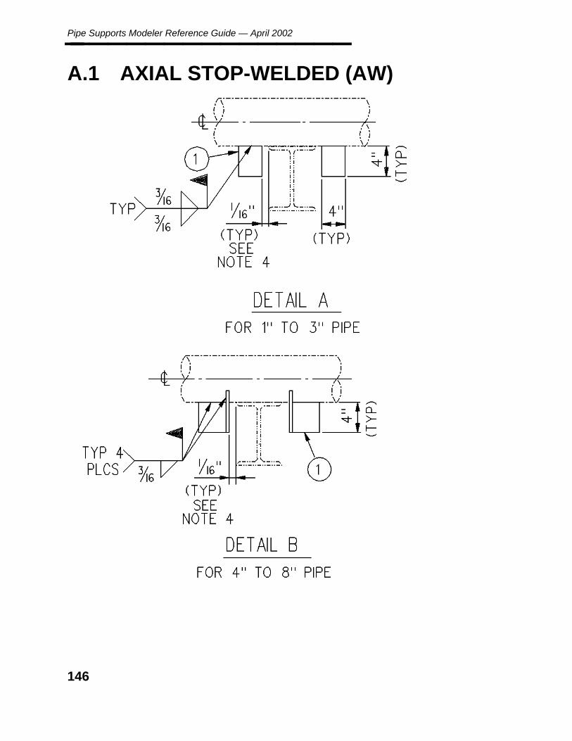
Pipe Supports Modeler Reference Guide — April 2002________________
A.1 AXIAL STOP-WELDED (AW)
146

Draw
ing
s
Appendix A: AXIAL STOP-WELDED (AW)________________
147

Pipe Supports Modeler Reference Guide — April 2002________________
148

Draw
ing
s
Appendix A: AXIAL STOP-WELDED (AW)________________
149

Pipe Supports Modeler Reference Guide — April 2002________________
A.2 CANTILEVER-BRACED (CB)
150

Draw
ing
s
Appendix A: CANTILEVER-BRACED (CB)________________
151

Pipe Supports Modeler Reference Guide — April 2002________________
152

Draw
ing
s
Appendix A: CANTILEVER-BRACED (CB)________________
153

Pipe Supports Modeler Reference Guide — April 2002________________
154
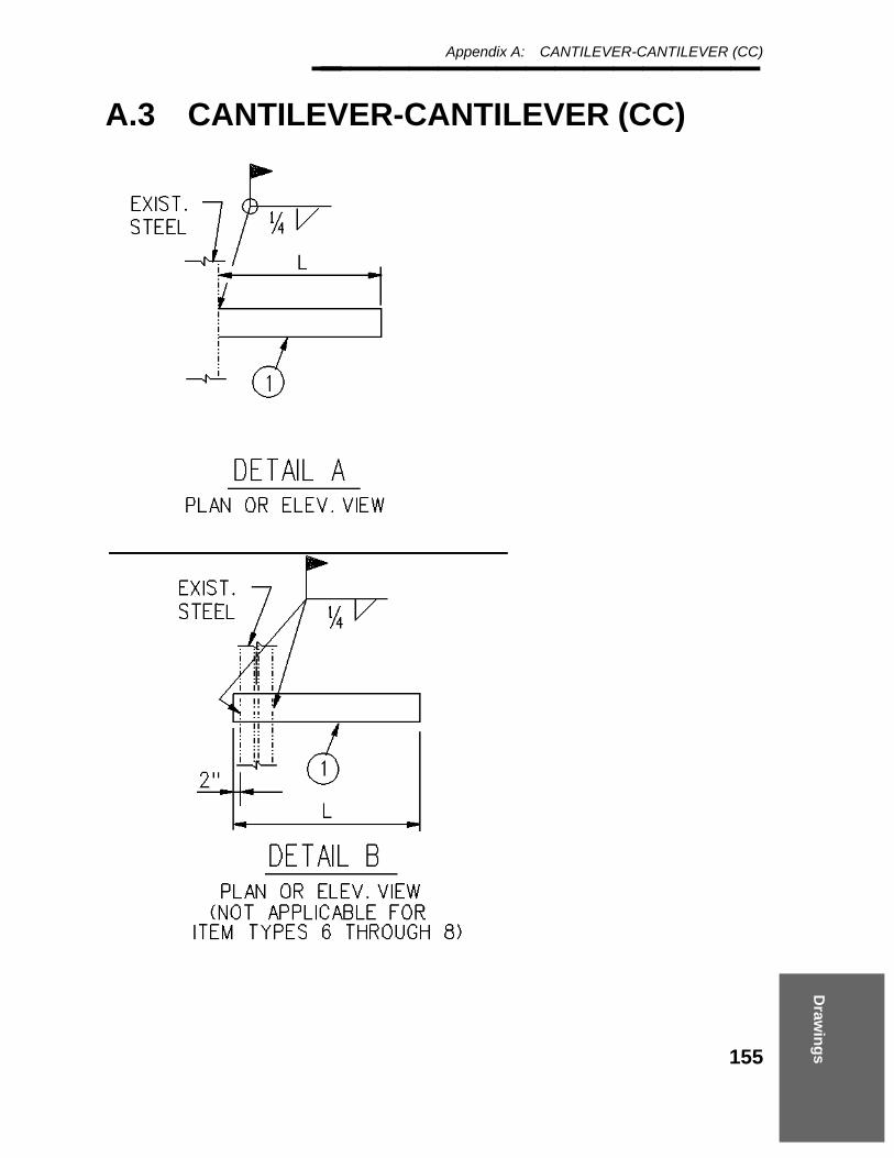
Draw
ing
s
Appendix A: CANTILEVER-CANTILEVER (CC)________________
A.3 CANTILEVER-CANTILEVER (CC)
155
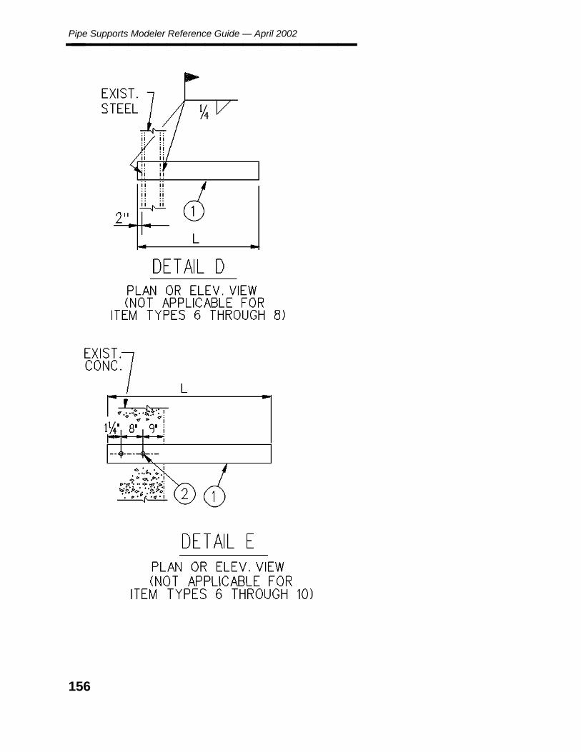
Pipe Supports Modeler Reference Guide — April 2002________________
156
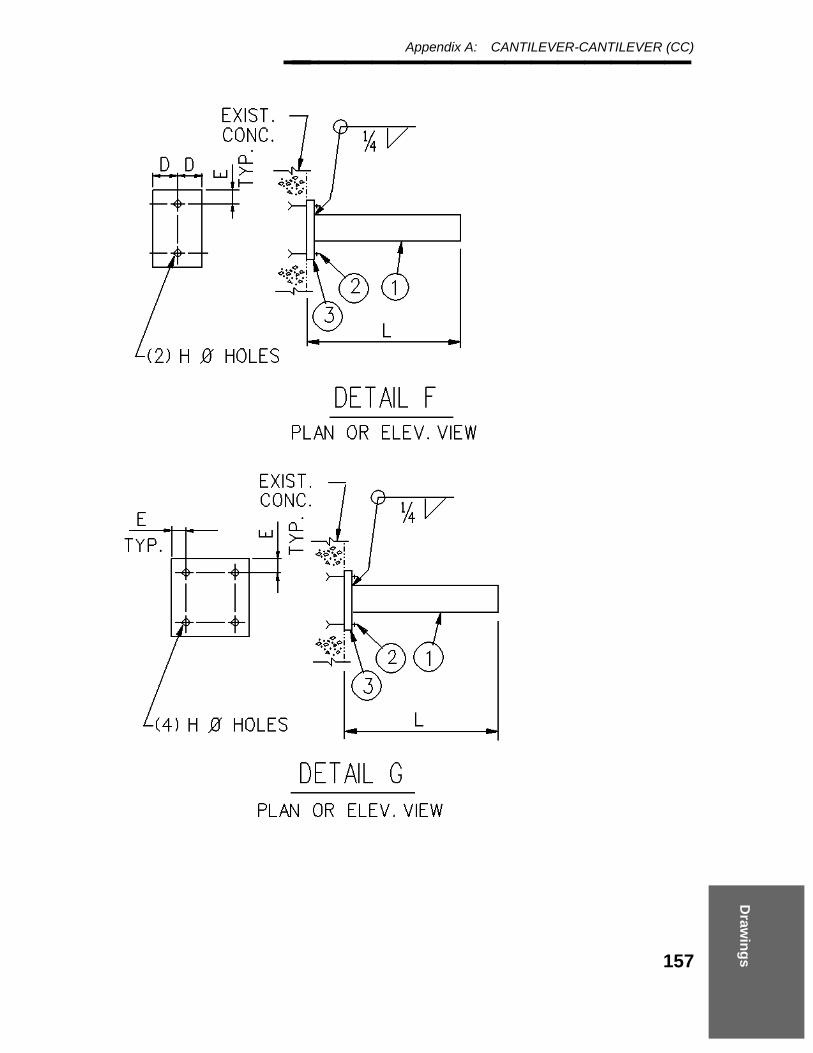
Draw
ing
s
Appendix A: CANTILEVER-CANTILEVER (CC)________________
157

Pipe Supports Modeler Reference Guide — April 2002________________
158
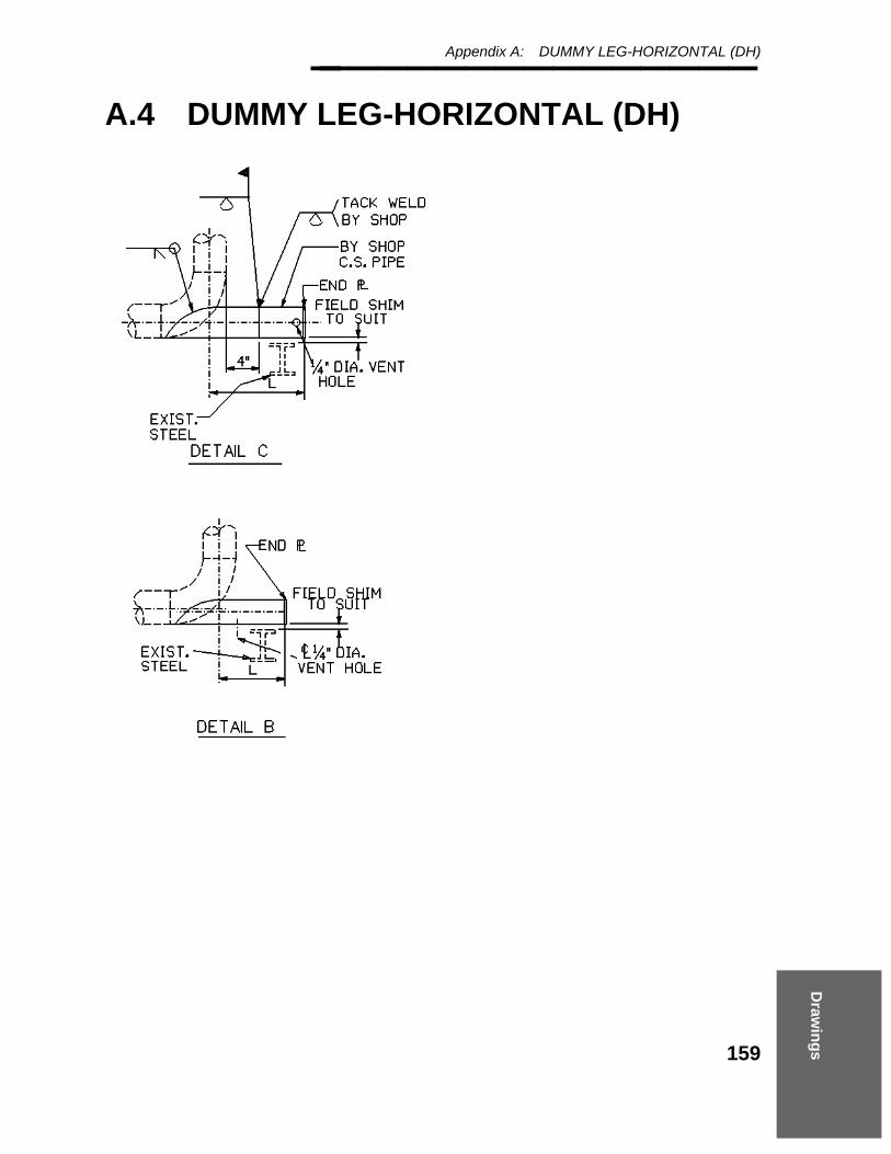
Draw
ing
s
Appendix A: DUMMY LEG-HORIZONTAL (DH)________________
A.4 DUMMY LEG-HORIZONTAL (DH)
159

Pipe Supports Modeler Reference Guide — April 2002________________
160

Draw
ing
s
Appendix A: DUMMY LEG-HORIZONTAL (DH)________________
161
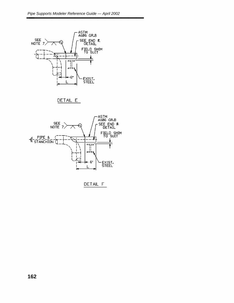
Pipe Supports Modeler Reference Guide — April 2002________________
162
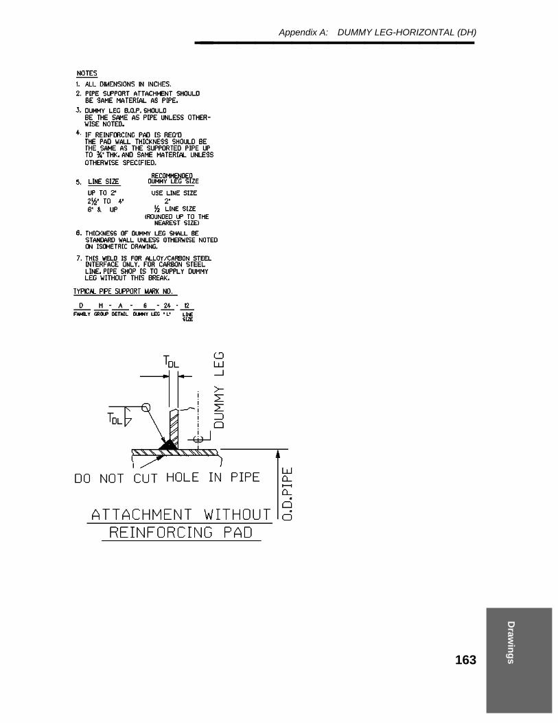
Draw
ing
s
Appendix A: DUMMY LEG-HORIZONTAL (DH)________________
163

Pipe Supports Modeler Reference Guide — April 2002________________
164

Draw
ing
s
Appendix A: DUMMY LEG-HORIZONTAL (DH)________________
165

Pipe Supports Modeler Reference Guide — April 2002________________
A.5 DUMMY LEG-HORIZONTAL (DH)
166

Draw
ing
s
Appendix A: DUMMY LEG-HORIZONTAL (DH)________________
167
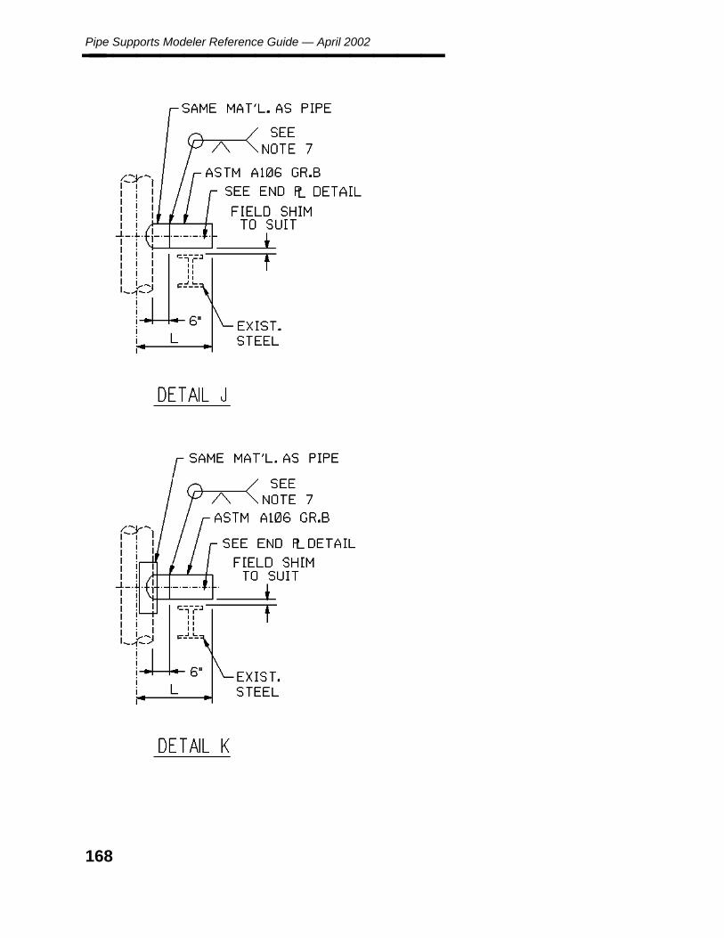
Pipe Supports Modeler Reference Guide — April 2002________________
168
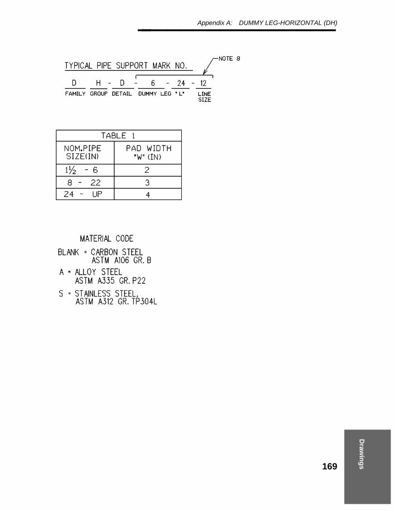
Draw
ing
s
Appendix A: DUMMY LEG-HORIZONTAL (DH)________________
169
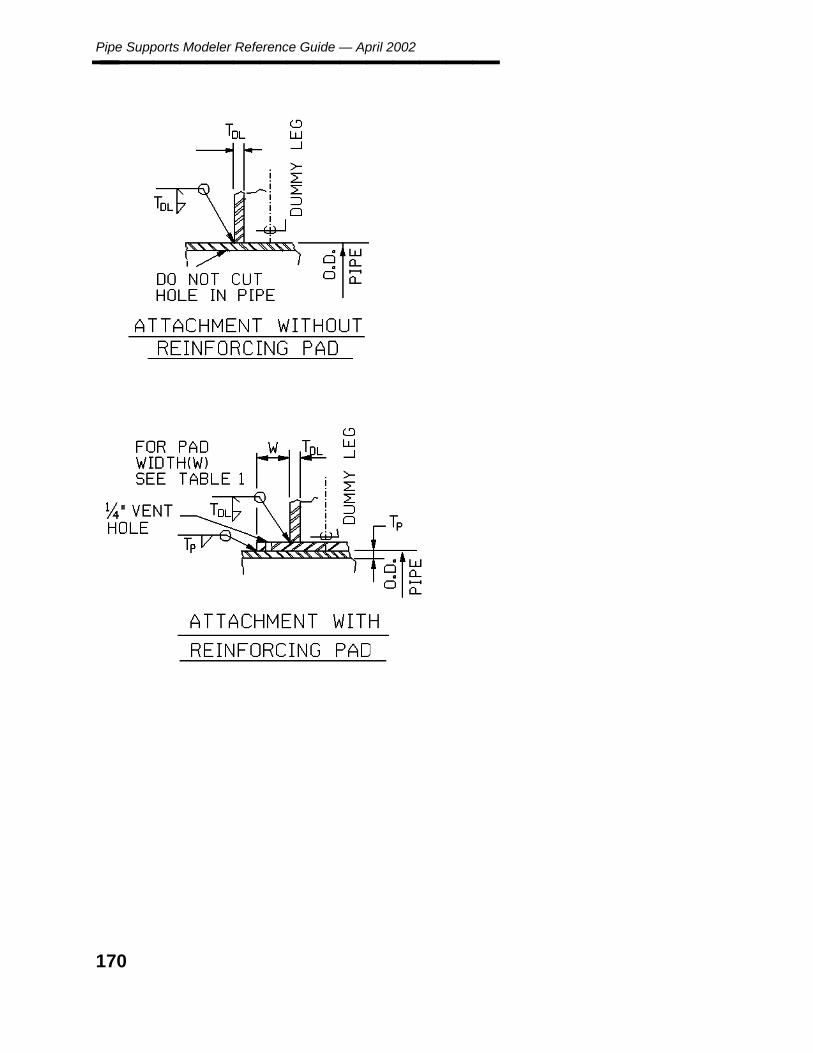
Pipe Supports Modeler Reference Guide — April 2002________________
170

Draw
ing
s
Appendix A: DUMMY LEG-VERTICAL (DV)________________
A.6 DUMMY LEG-VERTICAL (DV)
171
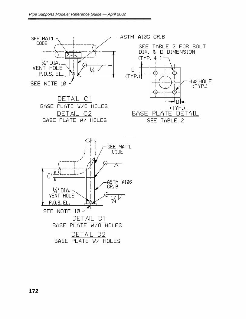
Pipe Supports Modeler Reference Guide — April 2002________________
172
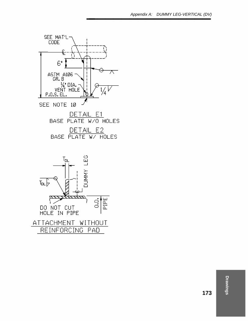
Draw
ing
s
Appendix A: DUMMY LEG-VERTICAL (DV)________________
173

Pipe Supports Modeler Reference Guide — April 2002________________
174

Draw
ing
s
Appendix A: DUMMY LEG-VERTICAL (DV)________________
175

Pipe Supports Modeler Reference Guide — April 2002________________
A.7 DUMMY LEG-VERTICAL (DV)
176

Draw
ing
s
Appendix A: DUMMY LEG-VERTICAL (DV)________________
177

Pipe Supports Modeler Reference Guide — April 2002________________
178

Draw
ing
s
Appendix A: DUMMY LEG-VERTICAL (DV)________________
179

Pipe Supports Modeler Reference Guide — April 2002________________
A.8 DUMMY LEG-VERTICAL (DV)
180
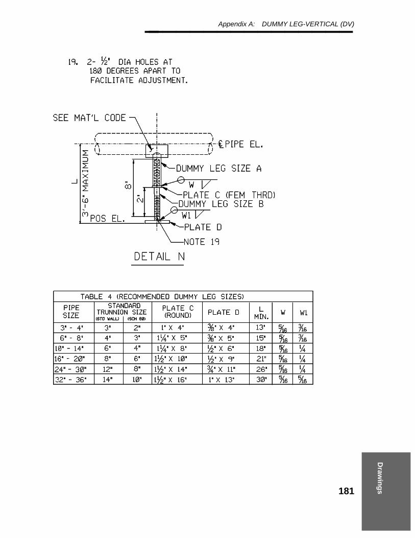
Draw
ing
s
Appendix A: DUMMY LEG-VERTICAL (DV)________________
181

Pipe Supports Modeler Reference Guide — April 2002________________
182

Draw
ing
s
Appendix A: DUMMY LEG-VERTICAL (DV)________________
A.9 DUMMY LEG-VERTICAL (DV)
183
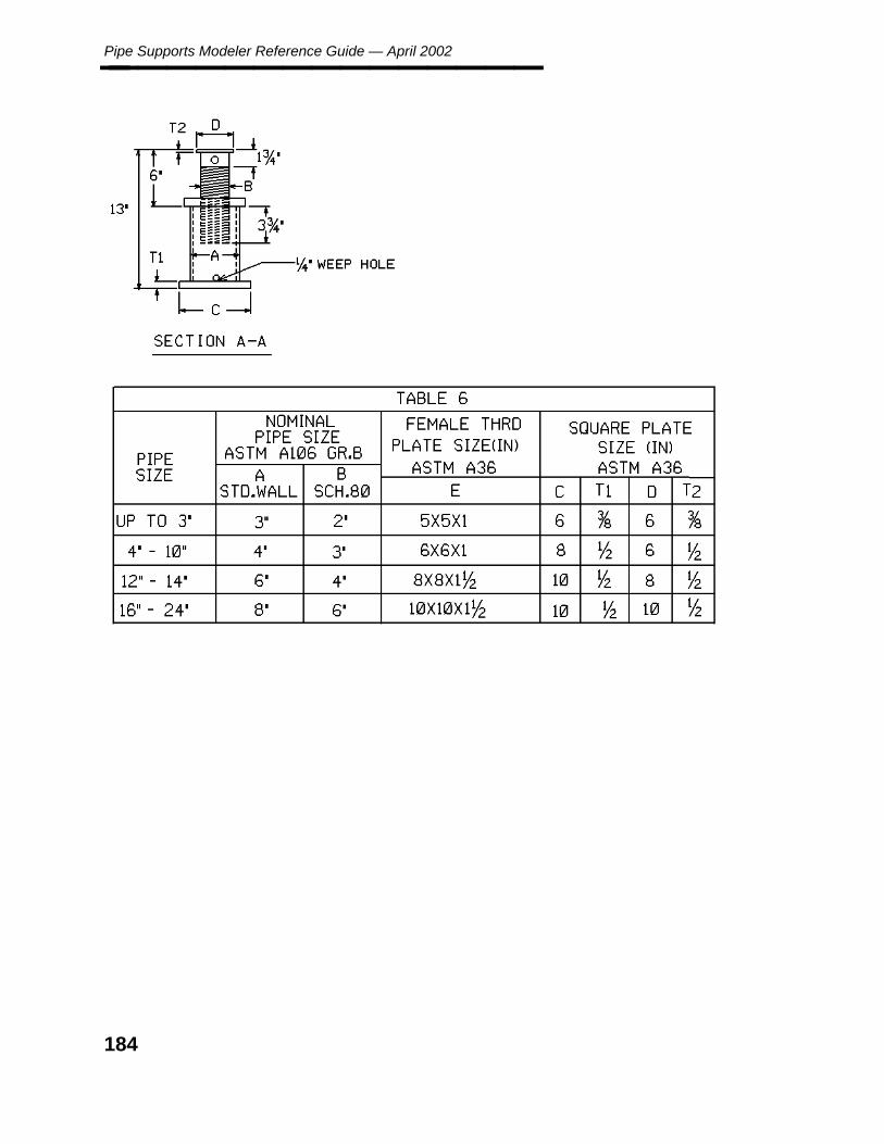
Pipe Supports Modeler Reference Guide — April 2002________________
184
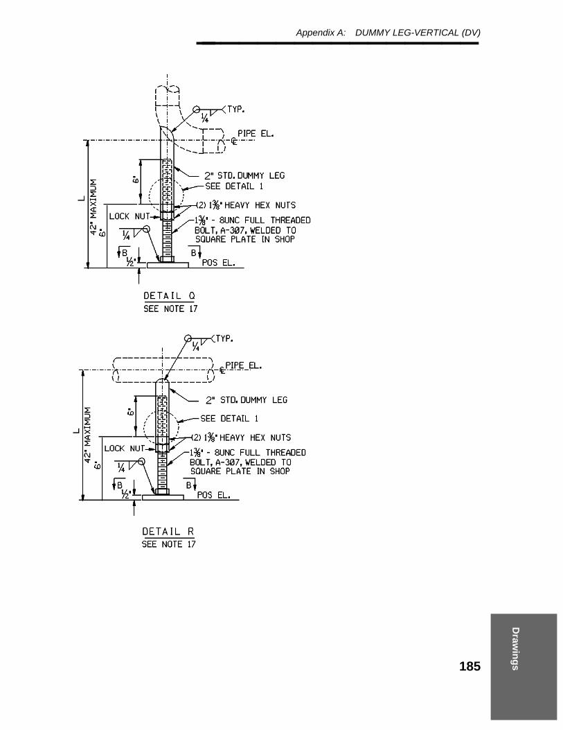
Draw
ing
s
Appendix A: DUMMY LEG-VERTICAL (DV)________________
185

Pipe Supports Modeler Reference Guide — April 2002________________
186

Draw
ing
s
Appendix A: FRAMES - FLANGED (FF)________________
A.10 FRAMES - FLANGED (FF)
187
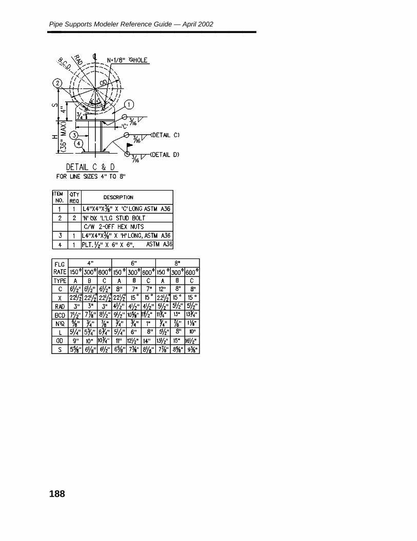
Pipe Supports Modeler Reference Guide — April 2002________________
188

Draw
ing
s
Appendix A: FRAMES - FLANGED (FF)________________
189
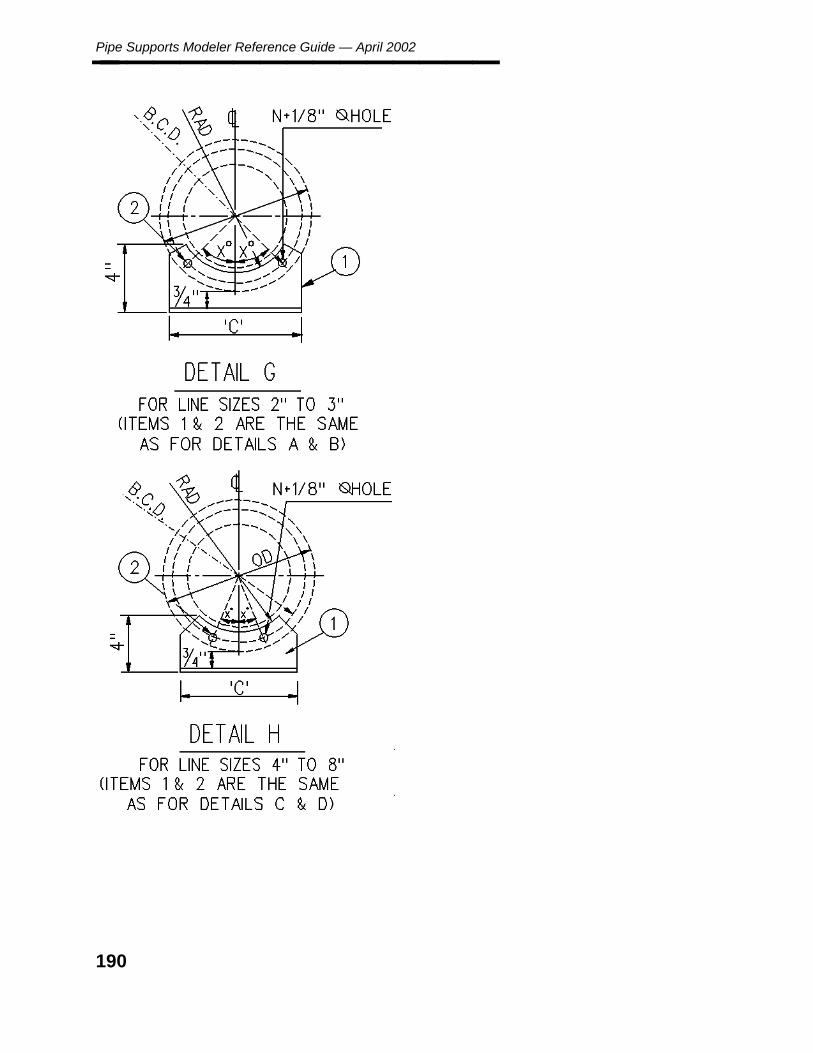
Pipe Supports Modeler Reference Guide — April 2002________________
190
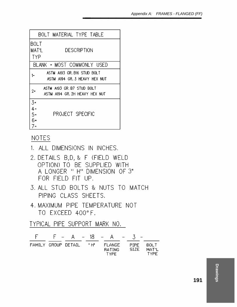
Draw
ing
s
Appendix A: FRAMES - FLANGED (FF)________________
191
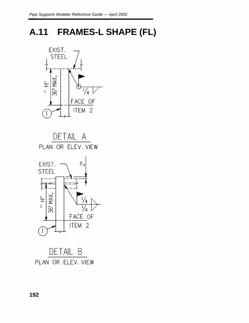
Pipe Supports Modeler Reference Guide — April 2002________________
A.11 FRAMES-L SHAPE (FL)
192

Draw
ing
s
Appendix A: FRAMES-L SHAPE (FL)________________
193
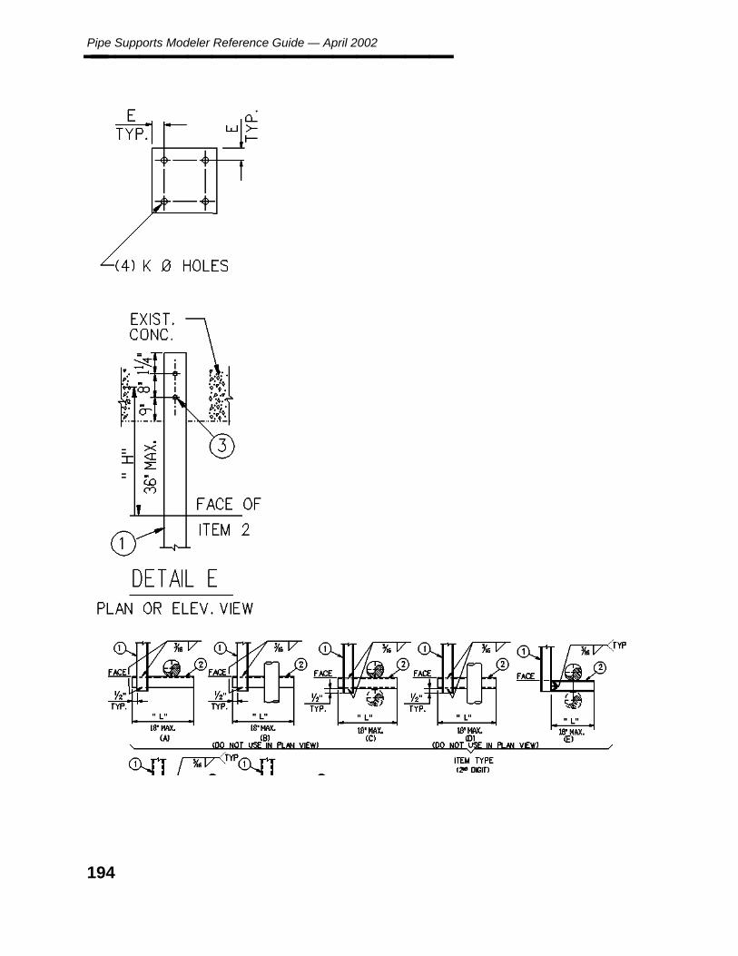
Pipe Supports Modeler Reference Guide — April 2002________________
194
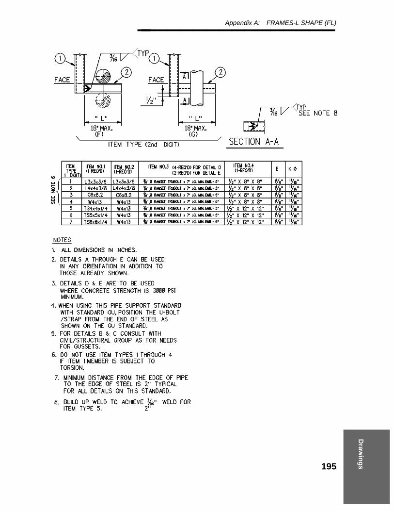
Draw
ing
s
Appendix A: FRAMES-L SHAPE (FL)________________
195

Pipe Supports Modeler Reference Guide — April 2002________________
196
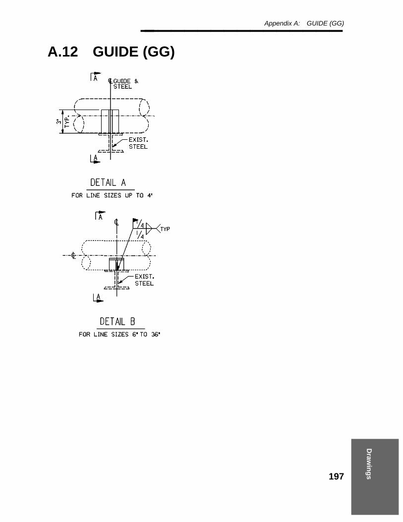
Draw
ing
s
Appendix A: GUIDE (GG)________________
A.12 GUIDE (GG)
197

Pipe Supports Modeler Reference Guide — April 2002________________
198

Draw
ing
s
Appendix A: GUIDE (GG)________________
199

Pipe Supports Modeler Reference Guide — April 2002________________
200

Draw
ing
s
Appendix A: GUIDE (GG)________________
201

Pipe Supports Modeler Reference Guide — April 2002________________
A.13 GUIDE (GG)
202

Draw
ing
s
Appendix A: GUIDE (GG)________________
203
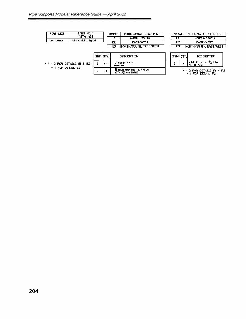
Pipe Supports Modeler Reference Guide — April 2002________________
204
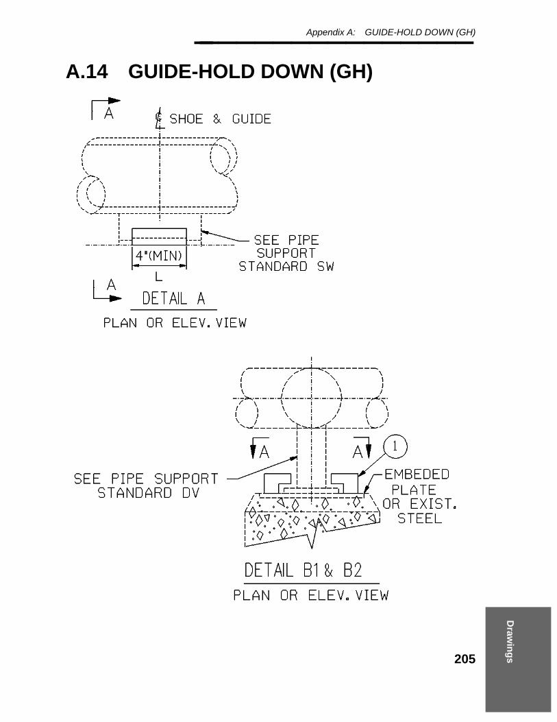
Draw
ing
s
Appendix A: GUIDE-HOLD DOWN (GH)________________
A.14 GUIDE-HOLD DOWN (GH)
205
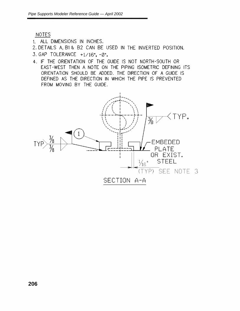
Pipe Supports Modeler Reference Guide — April 2002________________
206
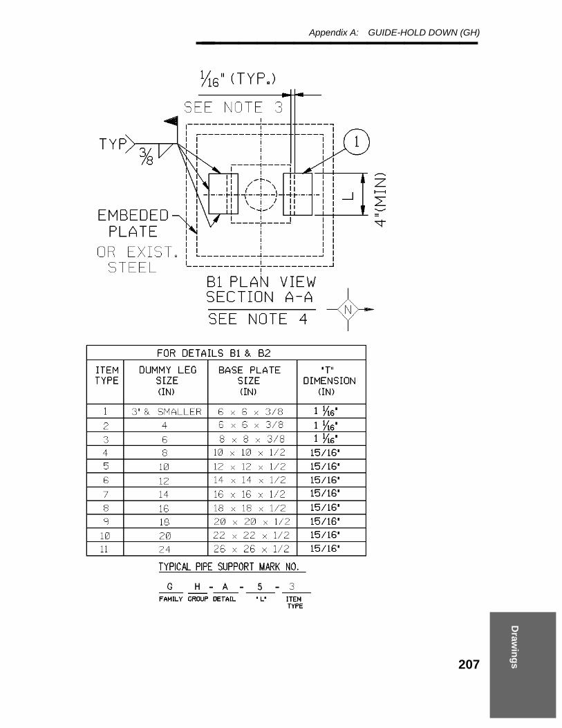
Draw
ing
s
Appendix A: GUIDE-HOLD DOWN (GH)________________
207
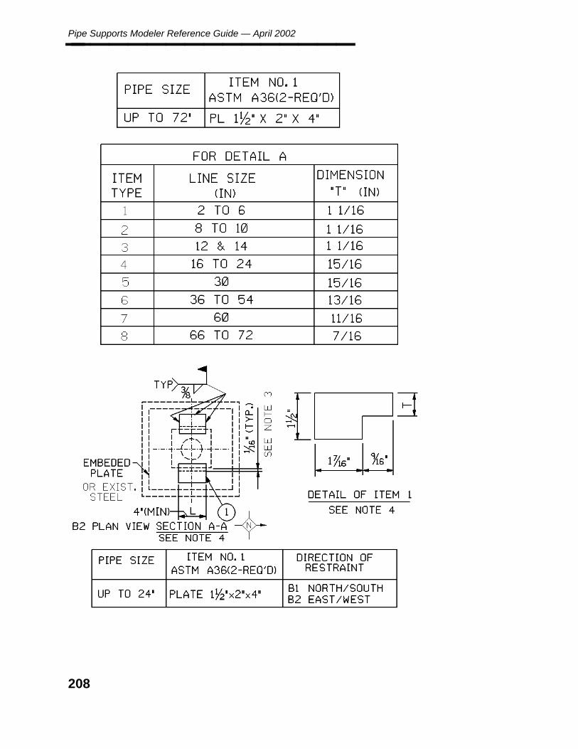
Pipe Supports Modeler Reference Guide — April 2002________________
208

Draw
ing
s
Appendix A: ROD HANGER (RH)________________
A.15 ROD HANGER (RH)
209

Pipe Supports Modeler Reference Guide — April 2002________________
210
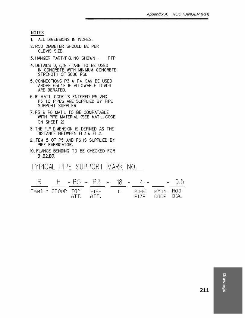
Draw
ing
s
Appendix A: ROD HANGER (RH)________________
211
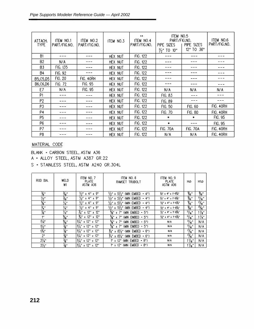
Pipe Supports Modeler Reference Guide — April 2002________________
212

Draw
ing
s
Appendix A: ROD HANGER (RH)________________
213

Pipe Supports Modeler Reference Guide — April 2002________________
214

Draw
ing
s
Appendix A: SHOE CLAMPED (SC)________________
A.16 SHOE CLAMPED (SC)
215

Pipe Supports Modeler Reference Guide — April 2002________________
216

Draw
ing
s
Appendix A: SHOE CLAMPED (SC)________________
217

Pipe Supports Modeler Reference Guide — April 2002________________
218

Draw
ing
s
Appendix A: SHOE WELDED (SW)________________
A.17 SHOE WELDED (SW)
219

Pipe Supports Modeler Reference Guide — April 2002________________
220
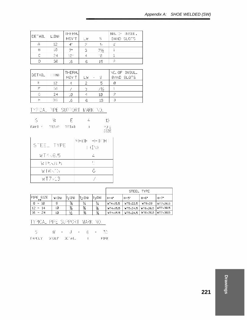
Draw
ing
s
Appendix A: SHOE WELDED (SW)________________
221
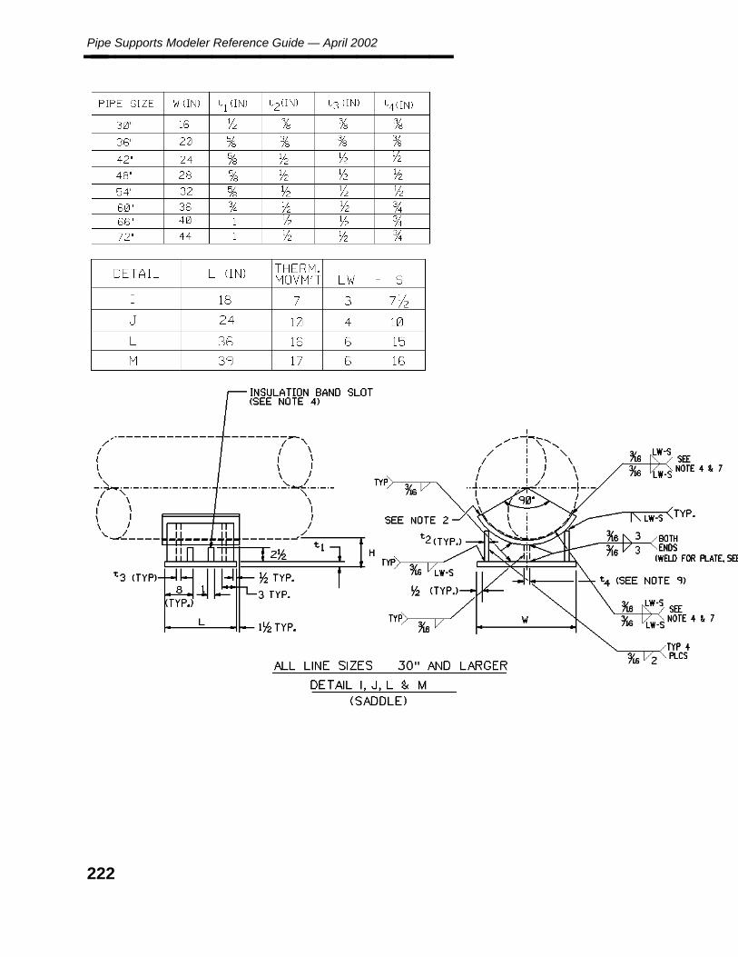
Pipe Supports Modeler Reference Guide — April 2002________________
222

Draw
ing
s
Appendix A: VESSEL-GUIDE (VG)________________
A.18 VESSEL-GUIDE (VG)
223

Pipe Supports Modeler Reference Guide — April 2002________________
224

Draw
ing
s
Appendix A: VESSEL-GUIDE (VG)________________
A.19 VESSEL-GUIDE (VG)
225
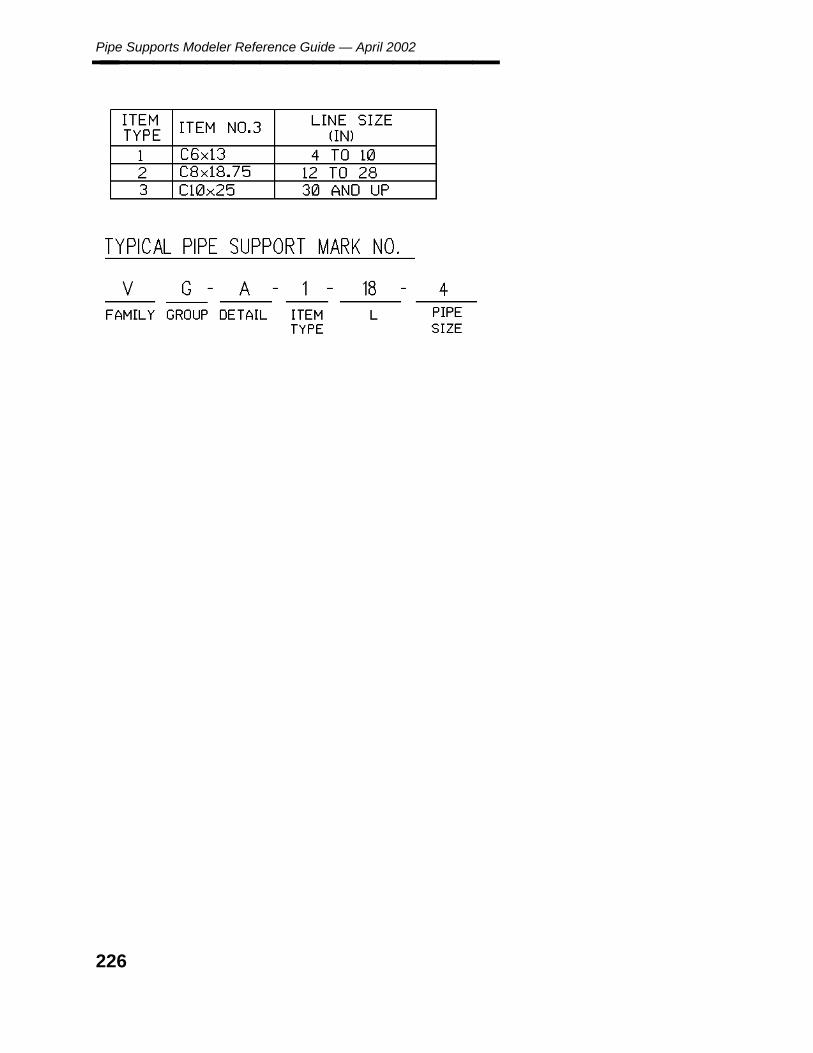
Pipe Supports Modeler Reference Guide — April 2002________________
226

Draw
ing
s
Appendix A: VESSEL-SUPPORT (VS)________________
A.20 VESSEL-SUPPORT (VS)
227
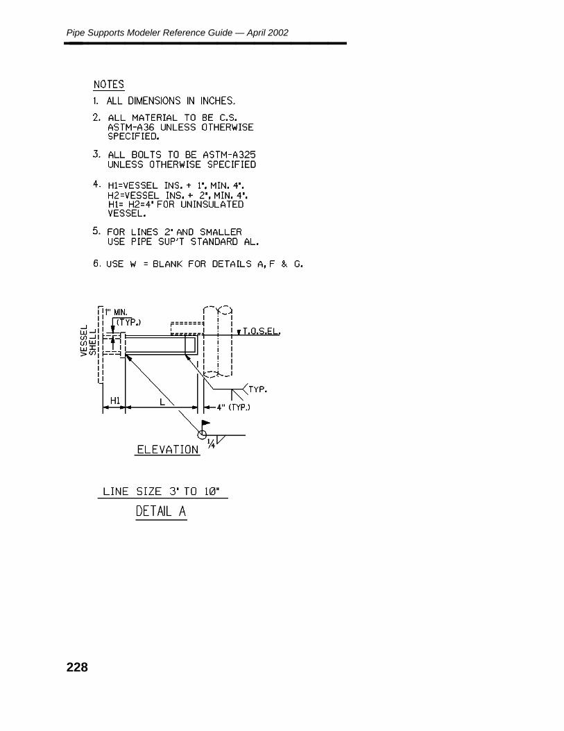
Pipe Supports Modeler Reference Guide — April 2002________________
228

Draw
ing
s
Appendix A: VESSEL-SUPPORT (VS)________________
229

Pipe Supports Modeler Reference Guide — April 2002________________
A.21 VESSEL-SUPPORT (VS)
230
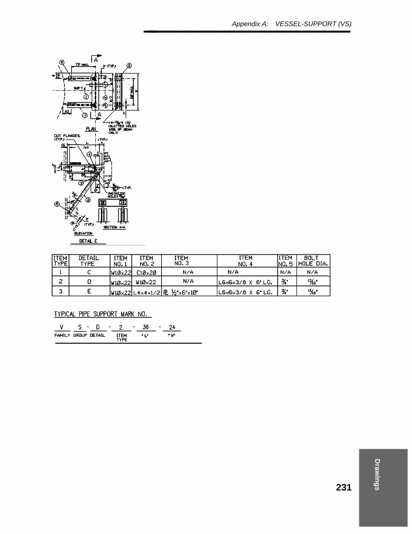
Draw
ing
s
Appendix A: VESSEL-SUPPORT (VS)________________
231
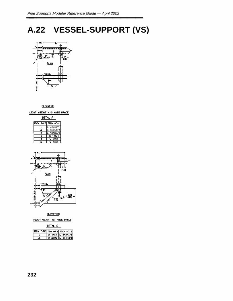
Pipe Supports Modeler Reference Guide — April 2002________________
A.22 VESSEL-SUPPORT (VS)
232
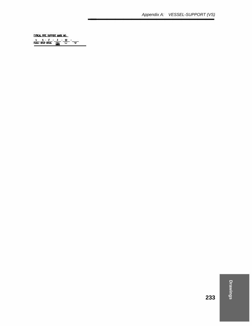
Draw
ing
s
Appendix A: VESSEL-SUPPORT (VS)________________
233

Pipe Supports Modeler Reference Guide — April 2002________________
A.23 VARIABLE SPRING HANGER (XV)
234

Draw
ing
s
Appendix A: VARIABLE SPRING HANGER (XV)________________
235

Pipe Supports Modeler Reference Guide — April 2002________________
236

Draw
ing
s
Appendix A: VARIABLE SPRING HANGER (XV)________________
237
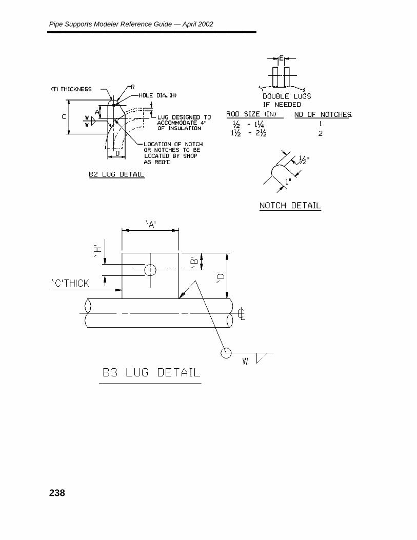
Pipe Supports Modeler Reference Guide — April 2002________________
238
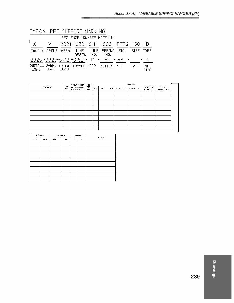
Draw
ing
s
Appendix A: VARIABLE SPRING HANGER (XV)________________
239

Pipe Supports Modeler Reference Guide — April 2002________________
240

Mo
men
t C
alculatio
ns
Appendix B: Moment Calculations________________
Appendix B Moment Calculations
241
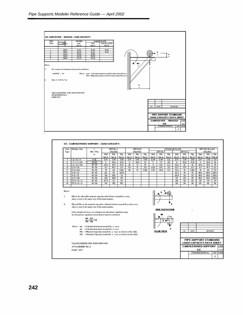
Pipe Supports Modeler Reference Guide — April 2002________________
242

Mo
men
t C
alculatio
ns
Appendix B: Moment Calculations________________
243

Pipe Supports Modeler Reference Guide — April 2002________________
244

Mo
men
t C
alculatio
ns
Appendix B: Moment Calculations________________
245

Pipe Supports Modeler Reference Guide — April 2002________________
246

Mo
men
t C
alculatio
ns
Appendix B: Moment Calculations________________
247
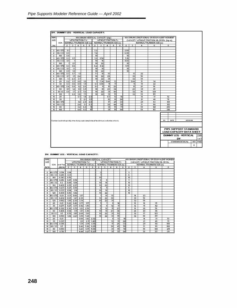
Pipe Supports Modeler Reference Guide — April 2002________________
248
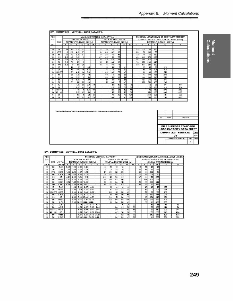
Mo
men
t C
alculatio
ns
Appendix B: Moment Calculations________________
249

Pipe Supports Modeler Reference Guide — April 2002________________
250
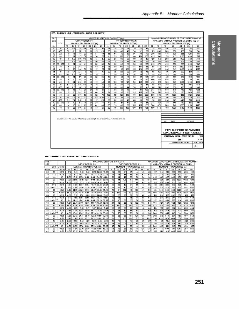
Mo
men
t C
alculatio
ns
Appendix B: Moment Calculations________________
251

Pipe Supports Modeler Reference Guide — April 2002________________
252
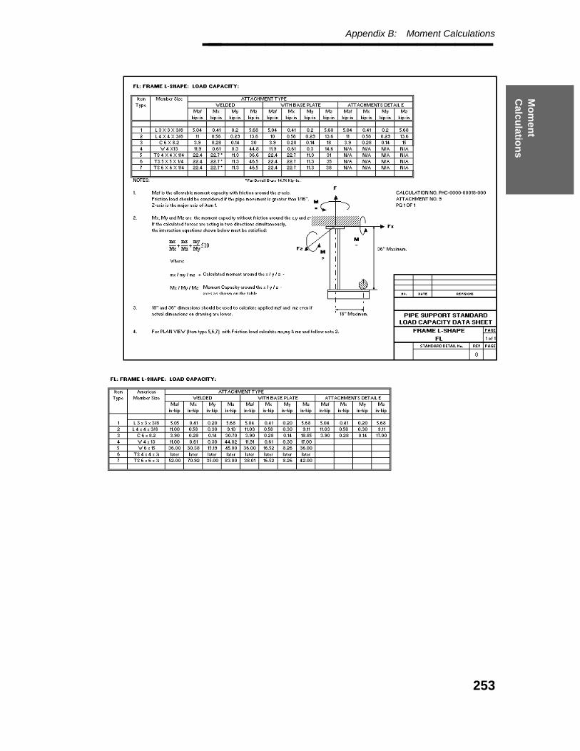
Mo
men
t C
alculatio
ns
Appendix B: Moment Calculations________________
253

Pipe Supports Modeler Reference Guide — April 2002________________
254

Mo
men
t C
alculatio
ns
Appendix B: Moment Calculations________________
255

Pipe Supports Modeler Reference Guide — April 2002________________
256
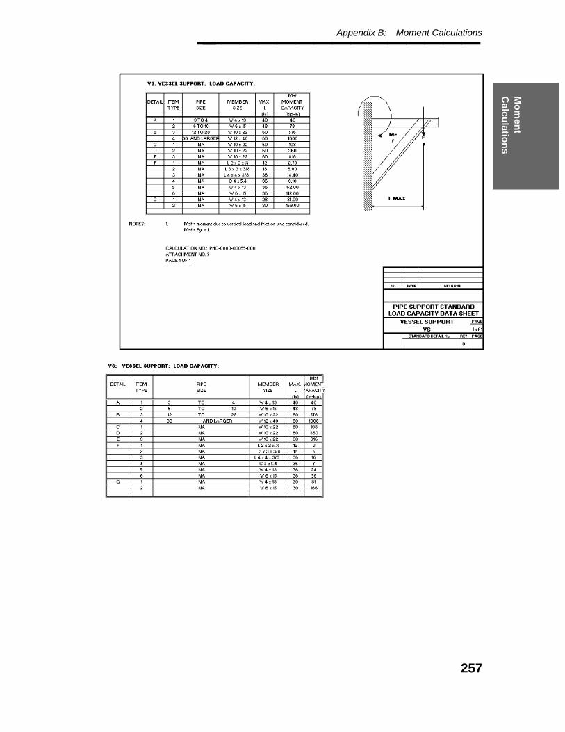
Mo
men
t C
alculatio
ns
Appendix B: Moment Calculations________________
257

Pipe Supports Modeler Reference Guide — April 2002________________
258
C. F
orm
s and
T
DF
s
Appendix C: Delivered Pipe Support Forms and Tutorial Definition Files________________
Appendix C Delivered PipeSupport Forms andTutorial DefinitionFiles
The following pipe supports are delivered with the PDS product.
CBA Cantilever - BracedCC Cantilever - CantileverDH Dummy Leg - HorizontalDV Dummy Leg - VerticalFF Frames FlangeFL Frames L-TypeGG Guide - GuideGH Guide - Hold DownRH Rod - HangerSC Shoe - ClampedSW Shoe - WeldedVG Vessel - GuideVS Vessel - SupportXV Variable Spring Hanger
259

Pipe Supports Modeler Reference Guide — April 2002________________
Cantilever - Braced (CBA)
CBA
1, 7, 2, 1, ’’, ’TAG’14, 7, 4, 1, ’"CB"’, ’TUTNO’15, 9, 38, 1, ’C38’, ’DATE’25, 9, 4, 4, ’’, ’ITEM_TYPE’26, 2, 11, 3, ’ 45’, ’ANGLE’45, 7, 39, 4, ’’, ’MARK_NO’46, 1, 5, 4, ’’, ’L’47, 3, 6, 4, ’’, ’Load’48, 9, 3, 1, ’’, ’Message’
260

C. F
orm
s and
T
DF
s
Appendix C: Cantilever - Cantilever (CC)________________
Cantilever - Cantilever (CC)
CC
1, 7, 2, 3, ’’, ’TAG’12, 1, 9, 3, ’0’, ’SHH’14, 7, 4, 1, ’"CC"’, ’TUTNO’15, 9, 38, 1, ’C38’, ’DATE’25, 9, 4, 4, ’’, ’ITEM_TYPE’44, 1, 37, 1, ’’, ’PIPE_TO_STEE’45, 7, 39, 1, ’’, ’MARK_NO’46, 1, 5, 4, ’’, ’L’47, 3, 6, 4, ’’, ’Load’48, 9, 3, 1, ’’, ’Message’
261
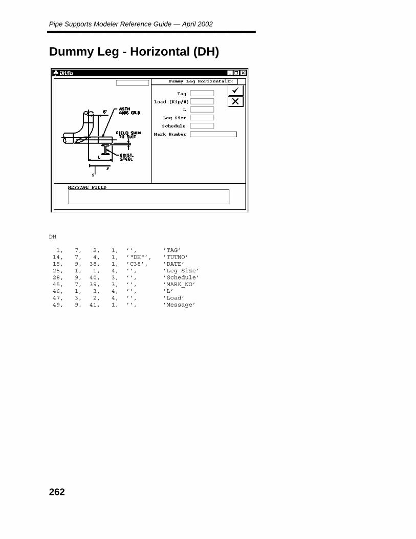
Pipe Supports Modeler Reference Guide — April 2002________________
Dummy Leg - Horizontal (DH)
DH
1, 7, 2, 1, ’’, ’TAG’14, 7, 4, 1, ’"DH"’, ’TUTNO’15, 9, 38, 1, ’C38’, ’DATE’25, 1, 1, 4, ’’, ’Leg Size’28, 9, 40, 3, ’’, ’Schedule’45, 7, 39, 3, ’’, ’MARK_NO’46, 1, 3, 4, ’’, ’L’47, 3, 2, 4, ’’, ’Load’49, 9, 41, 1, ’’, ’Message’
262
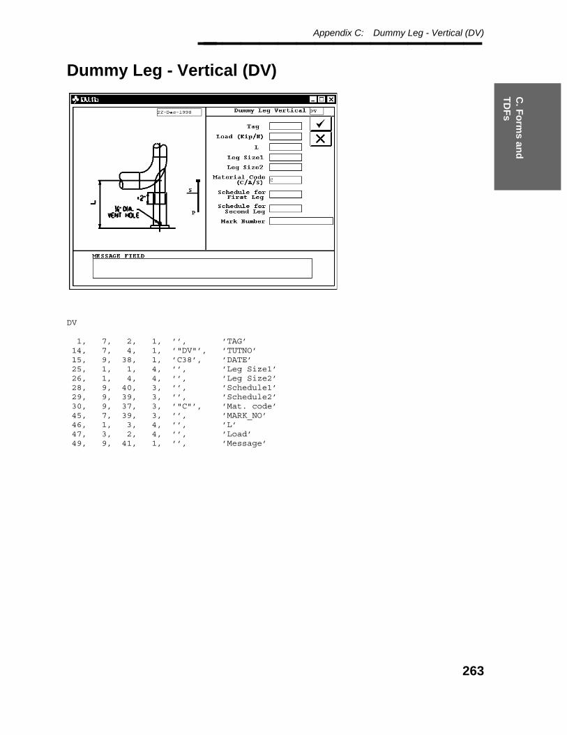
C. F
orm
s and
T
DF
s
Appendix C: Dummy Leg - Vertical (DV)________________
Dummy Leg - Vertical (DV)
DV
1, 7, 2, 1, ’’, ’TAG’14, 7, 4, 1, ’"DV"’, ’TUTNO’15, 9, 38, 1, ’C38’, ’DATE’25, 1, 1, 4, ’’, ’Leg Size1’26, 1, 4, 4, ’’, ’Leg Size2’28, 9, 40, 3, ’’, ’Schedule1’29, 9, 39, 3, ’’, ’Schedule2’30, 9, 37, 3, ’"C"’, ’Mat. code’45, 7, 39, 3, ’’, ’MARK_NO’46, 1, 3, 4, ’’, ’L’47, 3, 2, 4, ’’, ’Load’49, 9, 41, 1, ’’, ’Message’
263
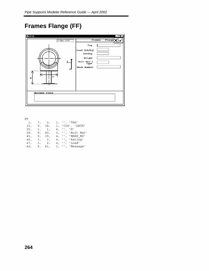
Pipe Supports Modeler Reference Guide — April 2002________________
Frames Flange (FF)
FF1, 7, 2, 1, ’’, ’TAG’
15, 9, 38, 1, ’C38’, ’DATE’25, 1, 1, 4, ’’, ’H’28, 9, 40, 3, ’’, ’Bolt Mat’45, 9, 39, 4, ’’, ’MARK_NO’46, 3, 3, 4, ’’, ’Rating’47, 3, 2, 4, ’’, ’Load’49, 9, 41, 1, ’’, ’Message’
264

C. F
orm
s and
T
DF
s
Appendix C: Frames L-Type (FL)________________
Frames L-Type (FL)
FL
1, 7, 2, 1, ’’, ’TAG’14, 7, 4, 1, ’"FL"’, ’TUTNO’15, 9, 38, 1, ’C38’, ’DATE’25, 1, 1, 4, ’36’, ’Height’28, 1, 2, 4, ’1’, ’Pipe_Move’31, 3, 3, 3, ’0’, ’Mx’32, 3, 4, 3, ’0’, ’My’33, 3, 5, 3, ’0’, ’Mz’37, 9, 37, 4, ’’, ’Item_Type_2’45, 7, 39, 4, ’’, ’Mark_No’46, 1, 7, 4, ’18’, ’Length’47, 3, 8, 4, ’2’, ’Load’49, 9, 40, 1, ’’, ’Message’50, 9, 39, 4, ’0’, ’Item_Type’51, 9, 38, 1, ’"N"’, ’Torsion’
265

Pipe Supports Modeler Reference Guide — April 2002________________
Guide - Guide (GG)
GG
15, 9, 38, 1, ’C38’, ’DATE’17, 7, 4, 1, ’"GG"’, ’TUTNO’24, 1, 8, 4, ’’, ’SHW’44, 1, 37, 1, ’’, ’PIPE_TO_STEE’45, 7, 39, 1, ’’, ’MARK_NO’46, 7, 2, 3, ’’, ’TAG’48, 9, 3, 1, ’’, ’Message’
266

C. F
orm
s and
T
DF
s
Appendix C: Guide - Hold Down (GH)________________
Guide - Hold Down (GH)
GH
15, 9, 38, 1, ’C38’, ’DATE’17, 7, 4, 1, ’"GH"’, ’TUTNO’24, 1, 8, 4, ’4’, ’BPW’44, 1, 37, 1, ’’, ’PIPE_TO_STEE’45, 7, 39, 1, ’’, ’MARK_NO’46, 7, 2, 3, ’’, ’TAG’48, 9, 3, 1, ’’, ’Message’
267

Pipe Supports Modeler Reference Guide — April 2002________________
Rod - Hanger (RH)
RH
1, 7, 2, 3, ’’, ’TAG’13, 3, 10, 4, ’100’, ’LOAD’14, 7, 4, 1, ’"RH"’, ’TUTNO’15, 9, 5, 1, ’C5’, ’DATE’16, 9, 15, 3, ’’, ’MATLCODE’45, 7, 39, 1, ’’, ’MARK_NO’48, 9, 6, 1, ’’, ’Message’
143, 9, 3, 4, ’"P1"’, ’BOT ATTACH’144, 9, 4, 4, ’"B5"’, ’TOP ATTACH’
268
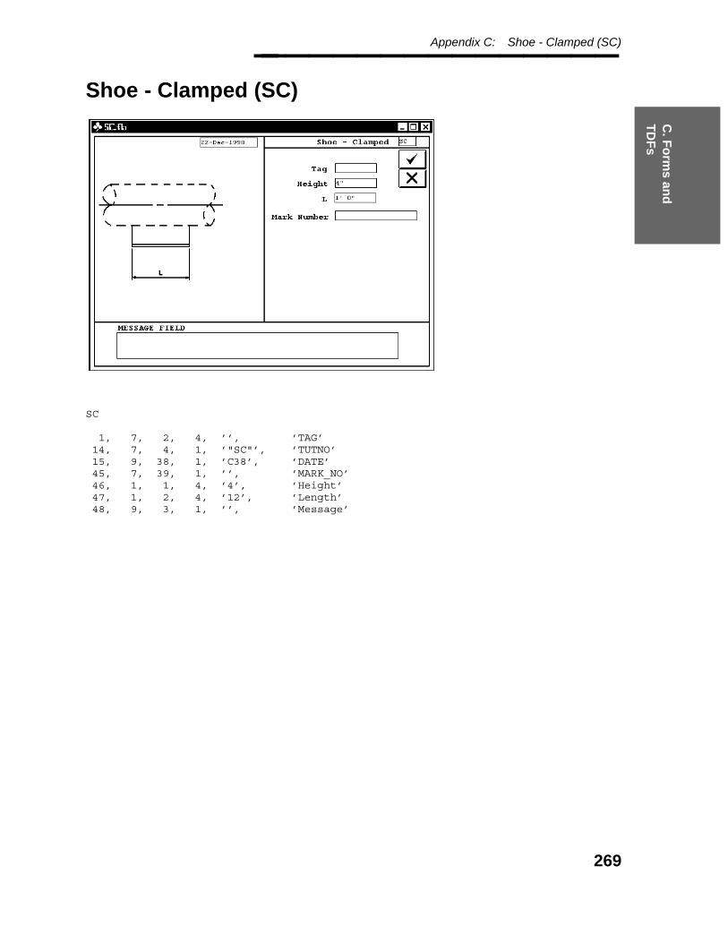
C. F
orm
s and
T
DF
s
Appendix C: Shoe - Clamped (SC)________________
Shoe - Clamped (SC)
SC
1, 7, 2, 4, ’’, ’TAG’14, 7, 4, 1, ’"SC"’, ’TUTNO’15, 9, 38, 1, ’C38’, ’DATE’45, 7, 39, 1, ’’, ’MARK_NO’46, 1, 1, 4, ’4’, ’Height’47, 1, 2, 4, ’12’, ’Length’48, 9, 3, 1, ’’, ’Message’
269

Pipe Supports Modeler Reference Guide — April 2002________________
Shoe - Welded (SW)
SW
1, 7, 2, 4, ’’, ’TAG’14, 7, 4, 1, ’"SC"’, ’TUTNO’15, 9, 38, 1, ’C38’, ’DATE’45, 7, 39, 1, ’’, ’MARK_NO’46, 1, 1, 4, ’4’, ’Height’47, 1, 2, 4, ’12’, ’Length’48, 9, 3, 1, ’’, ’Message’
270

C. F
orm
s and
T
DF
s
Appendix C: Vessel - Guide (VG)________________
Vessel - Guide (VG)
VG
1, 7, 2, 3, ’’, ’TAG’14, 7, 4, 1, ’"VG"’, ’TUTNO’15, 9, 38, 1, ’C38’, ’DATE’25, 9, 4, 4, ’’, ’ITEM_TYPE’44, 1, 37, 1, ’’, ’PIPE_TO_STEE’45, 7, 39, 1, ’’, ’MARK_NO’46, 1, 5, 4, ’’, ’L’47, 3, 6, 4, ’’, ’Load’48, 9, 3, 1, ’’, ’Message’
271
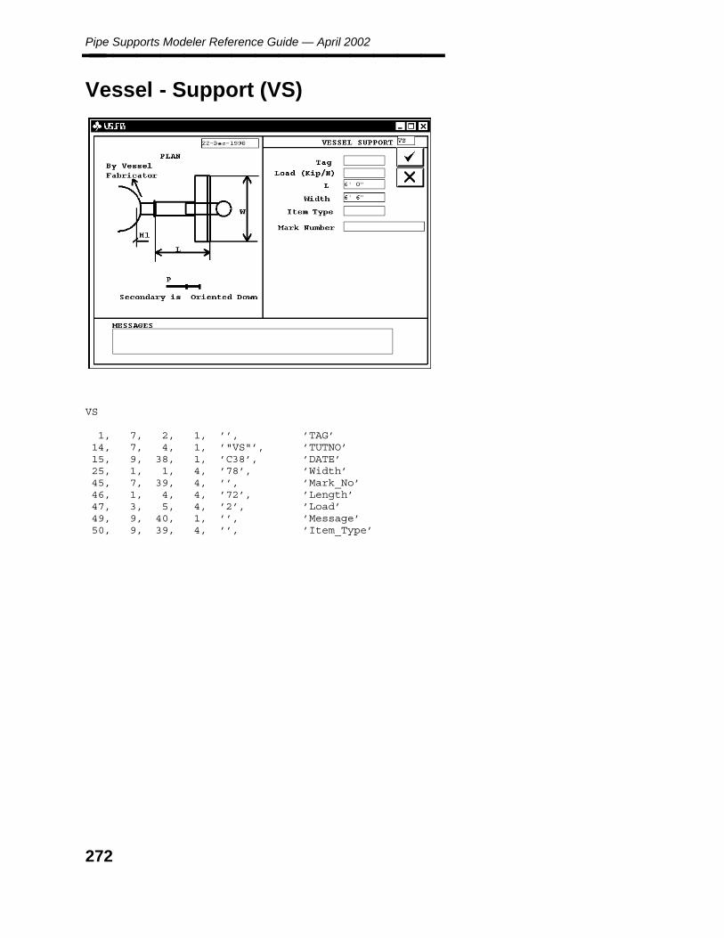
Pipe Supports Modeler Reference Guide — April 2002________________
Vessel - Support (VS)
VS
1, 7, 2, 1, ’’, ’TAG’14, 7, 4, 1, ’"VS"’, ’TUTNO’15, 9, 38, 1, ’C38’, ’DATE’25, 1, 1, 4, ’78’, ’Width’45, 7, 39, 4, ’’, ’Mark_No’46, 1, 4, 4, ’72’, ’Length’47, 3, 5, 4, ’2’, ’Load’49, 9, 40, 1, ’’, ’Message’50, 9, 39, 4, ’’, ’Item_Type’
272

C. F
orm
s and
T
DF
s
Appendix C: Variable Spring Hanger (XV)________________
Variable Spring Hanger (XV)
XV1, 7, 2, 1, ’’, ’TAG’
13, 3, 10, 4, ’1000’, ’LOAD’15, 9, 5, 1, ’C5’, ’DATE’16, 1, 8, 4, ’-0.25’, ’TOT MOVMT1’23, 1, 12, 3, ’’, ’c_c length’24, 1, 15, 3, ’’, ’distance’32, 3, 7, 3, ’’, ’Hydro load’45, 7, 39, 4, ’’, ’MARK_NO’48, 9, 6, 1, ’’, ’Message’
141, 3, 1, 4, ’1’, ’TYPE’142, 3, 2, 4, ’100’, ’SIZE’143, 9, 3, 4, ’"B1"’, ’BOT ATTACH’144, 9, 4, 3, ’’, ’TOP ATTACH’145, 9, 5, 3, ’’, ’TOP PLATE’
273

Pipe Supports Modeler Reference Guide — April 2002________________
274
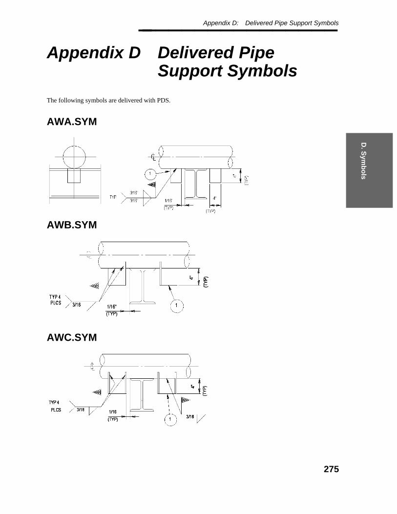
D. S
ymb
ols
Appendix D: Delivered Pipe Support Symbols________________
Appendix D Delivered PipeSupport Symbols
The following symbols are delivered with PDS.
AWA.SYM
AWB.SYM
AWC.SYM
275

Pipe Supports Modeler Reference Guide — April 2002________________
AWD.SYM
AWE.SYM
AWF.SYM
276
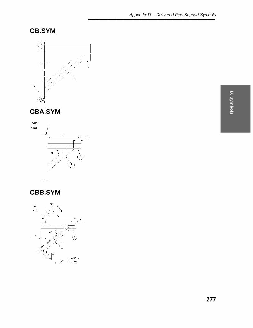
D. S
ymb
ols
Appendix D: Delivered Pipe Support Symbols________________
CB.SYM
CBA.SYM
CBB.SYM
277
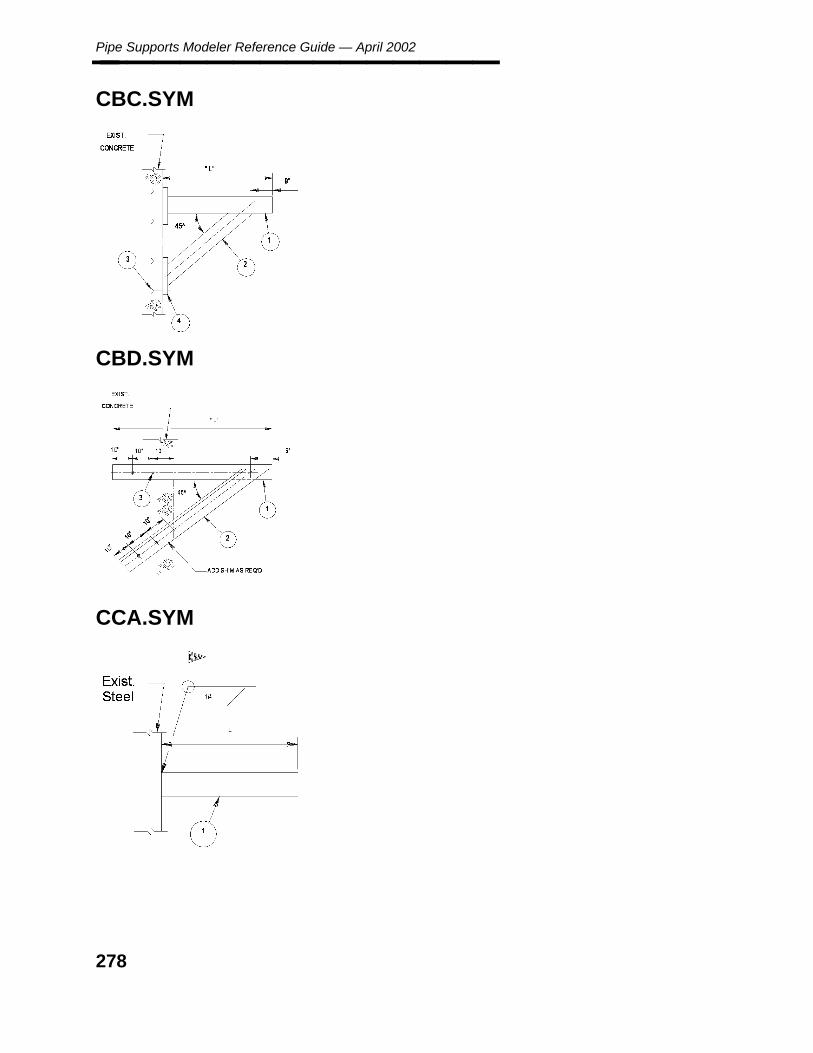
Pipe Supports Modeler Reference Guide — April 2002________________
CBC.SYM
CBD.SYM
CCA.SYM
278

D. S
ymb
ols
Appendix D: Delivered Pipe Support Symbols________________
CCB.SYM
CCD.SYM
CCE.SYM
279

Pipe Supports Modeler Reference Guide — April 2002________________
CCF.SYM
CCG.SYM
DHA.SYM
280

D. S
ymb
ols
Appendix D: Delivered Pipe Support Symbols________________
DHB.SYM
DHC.SYM
DHD.SYM
281
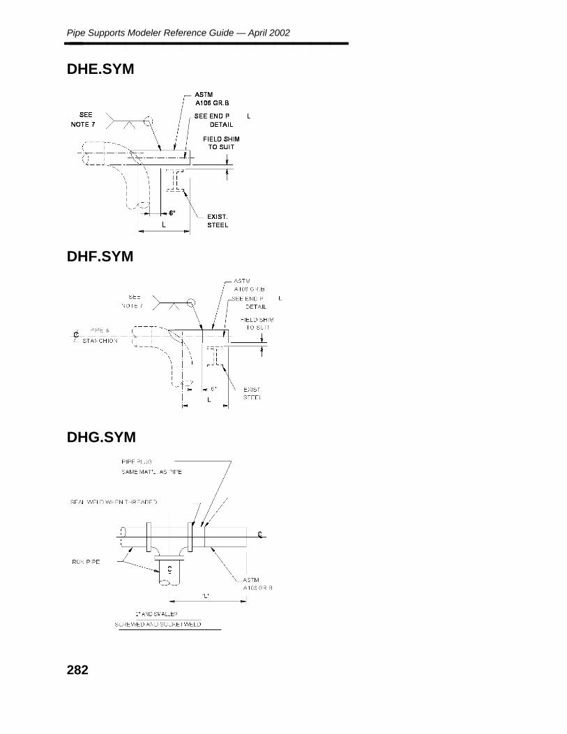
Pipe Supports Modeler Reference Guide — April 2002________________
DHE.SYM
DHF.SYM
DHG.SYM
282

D. S
ymb
ols
Appendix D: Delivered Pipe Support Symbols________________
DHH.SYM
DHI.SYM
DHJ.SYM
283
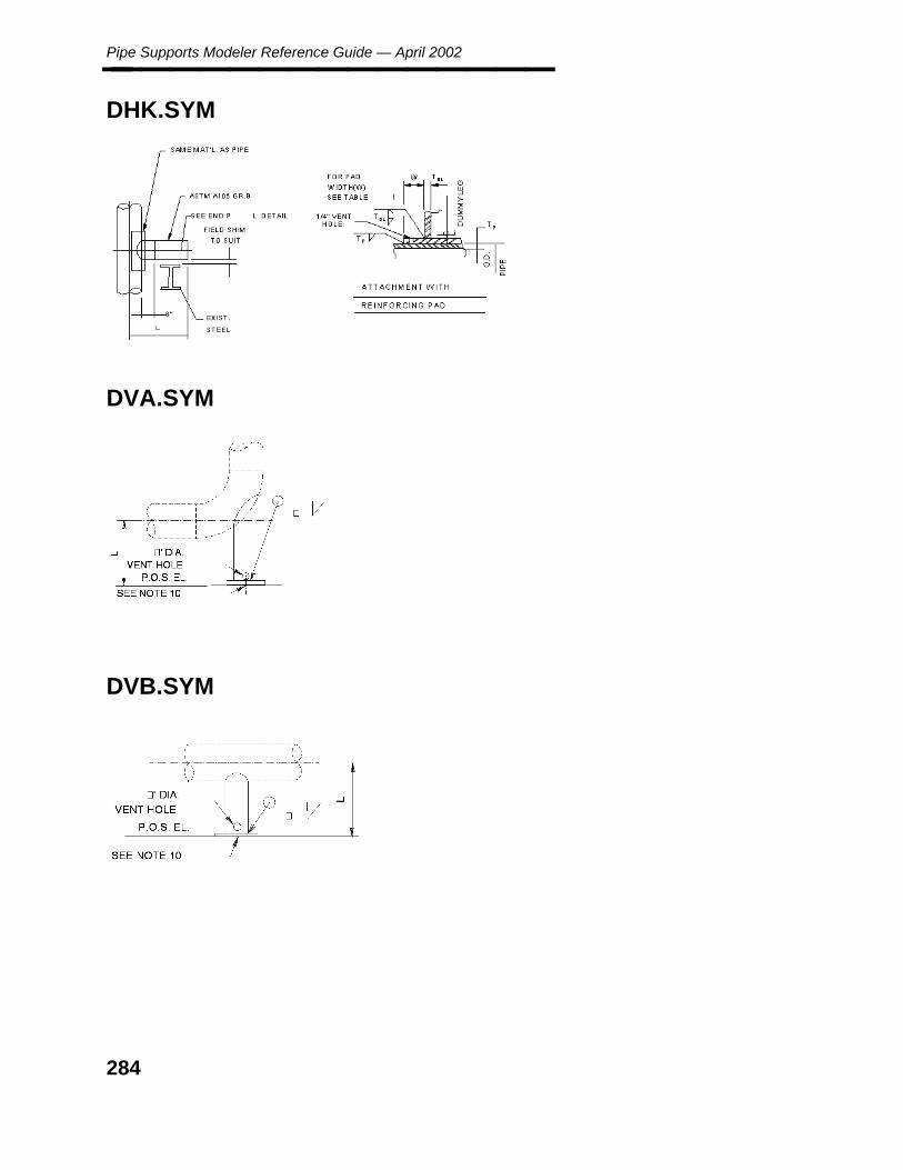
Pipe Supports Modeler Reference Guide — April 2002________________
DHK.SYM
DVA.SYM
DVB.SYM
284
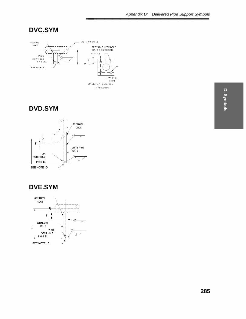
D. S
ymb
ols
Appendix D: Delivered Pipe Support Symbols________________
DVC.SYM
DVD.SYM
DVE.SYM
285
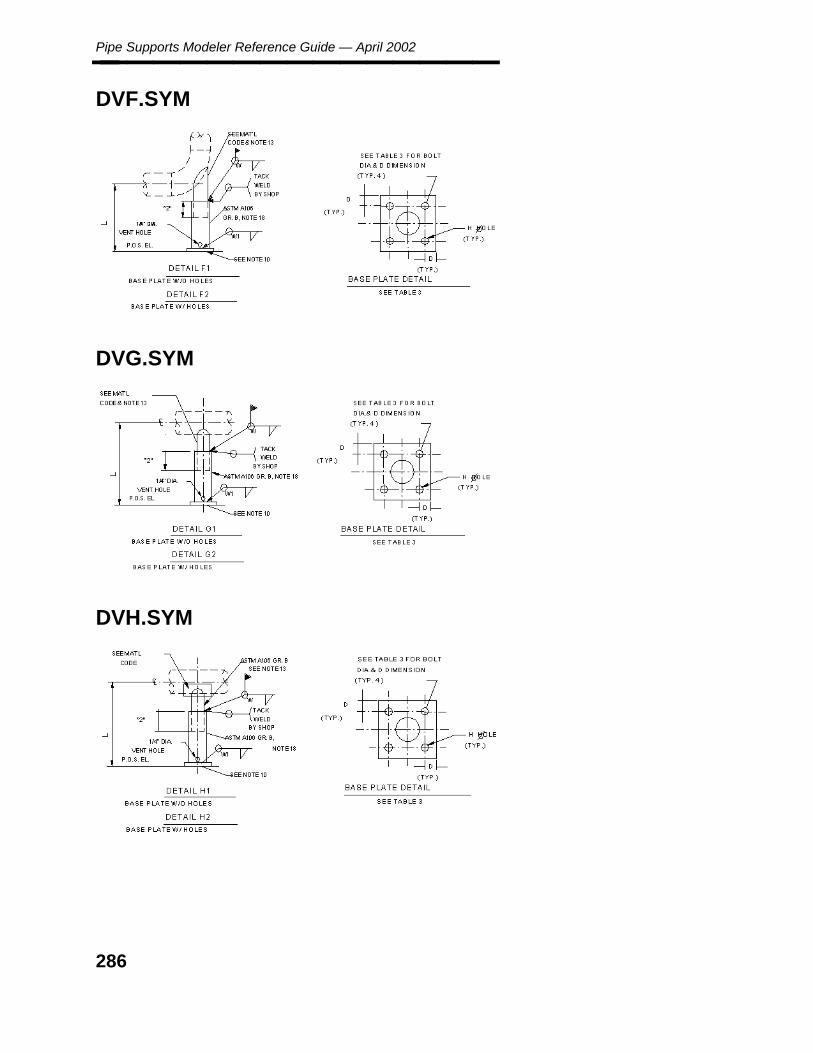
Pipe Supports Modeler Reference Guide — April 2002________________
DVF.SYM
DVG.SYM
DVH.SYM
286

D. S
ymb
ols
Appendix D: Delivered Pipe Support Symbols________________
DVJ.SYM
DVK.SYM
DVL.SYM
287

Pipe Supports Modeler Reference Guide — April 2002________________
DVM.SYM
DVN.SYM
DVO.SYM
288

D. S
ymb
ols
Appendix D: Delivered Pipe Support Symbols________________
DVP.SYM
DVQ.SYM
289

Pipe Supports Modeler Reference Guide — April 2002________________
DVR.SYM
DWGAPLAN.SYM
DWGARROW.SYM
290
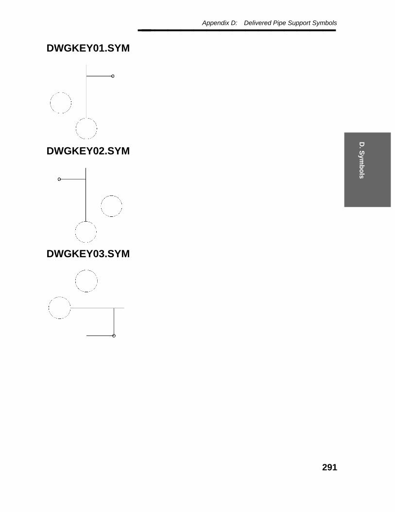
D. S
ymb
ols
Appendix D: Delivered Pipe Support Symbols________________
DWGKEY01.SYM
DWGKEY02.SYM
DWGKEY03.SYM
291
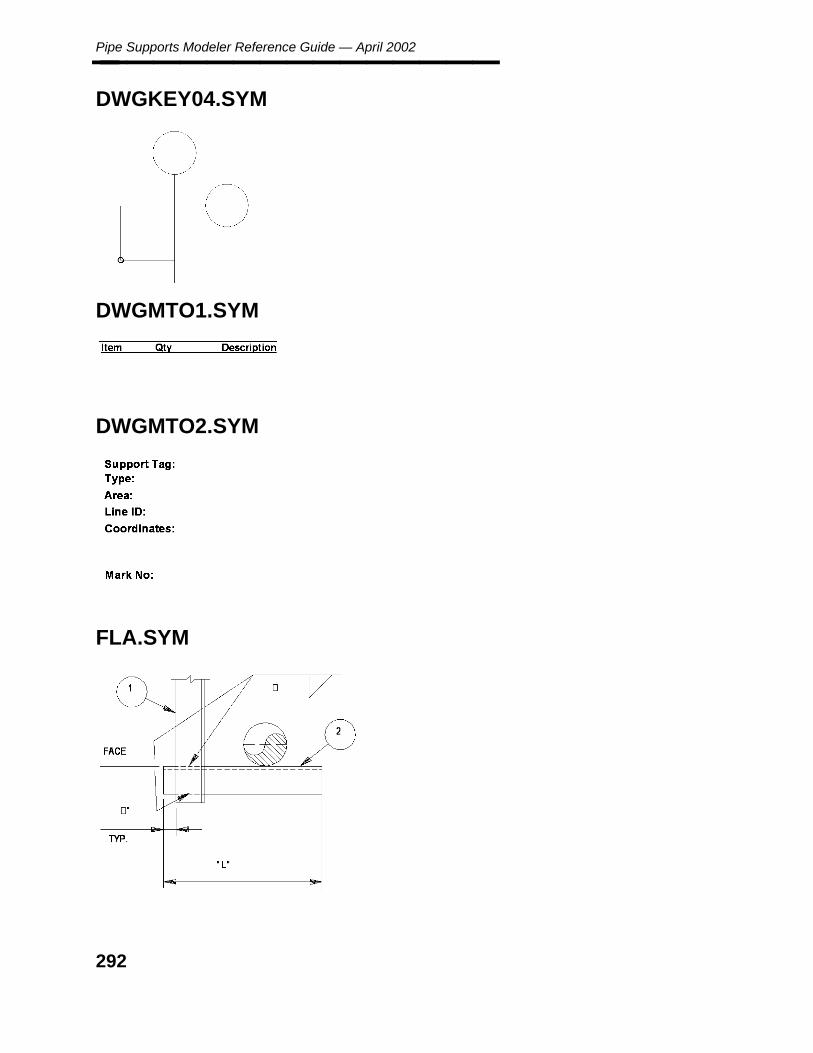
Pipe Supports Modeler Reference Guide — April 2002________________
DWGKEY04.SYM
DWGMTO1.SYM
DWGMTO2.SYM
FLA.SYM
292

D. S
ymb
ols
Appendix D: Delivered Pipe Support Symbols________________
FLB.SYM
FLC.SYM
FLD.SYM
293

Pipe Supports Modeler Reference Guide — April 2002________________
FLE.SYM
FLF.SYM
294

D. S
ymb
ols
Appendix D: Delivered Pipe Support Symbols________________
FLG.SYM
GGA.SYM
GGB.SYM
295

Pipe Supports Modeler Reference Guide — April 2002________________
GGC.SYM
GGD.SYM
GGE.SYM
296

D. S
ymb
ols
Appendix D: Delivered Pipe Support Symbols________________
GGE1.SYM
GGE2.SYM
GGE3.SYM
297

Pipe Supports Modeler Reference Guide — April 2002________________
GGF1.SYM
GGF2.SYM
GGF3.SYM
298
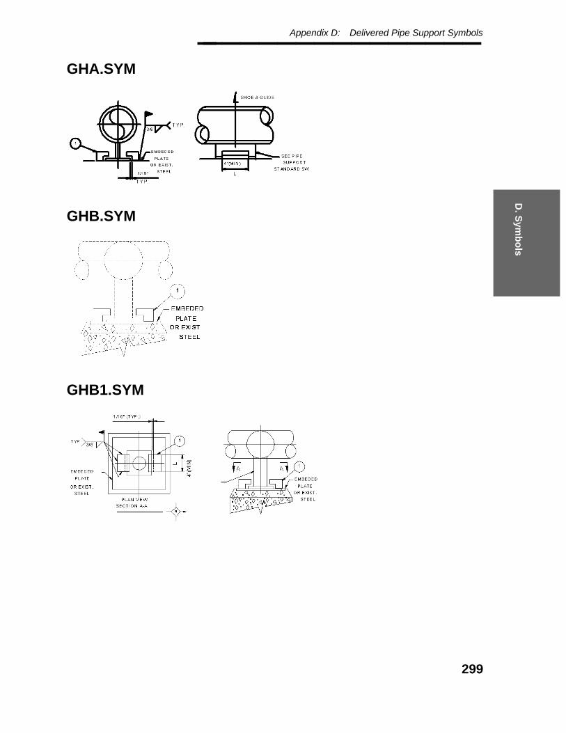
D. S
ymb
ols
Appendix D: Delivered Pipe Support Symbols________________
GHA.SYM
GHB.SYM
GHB1.SYM
299
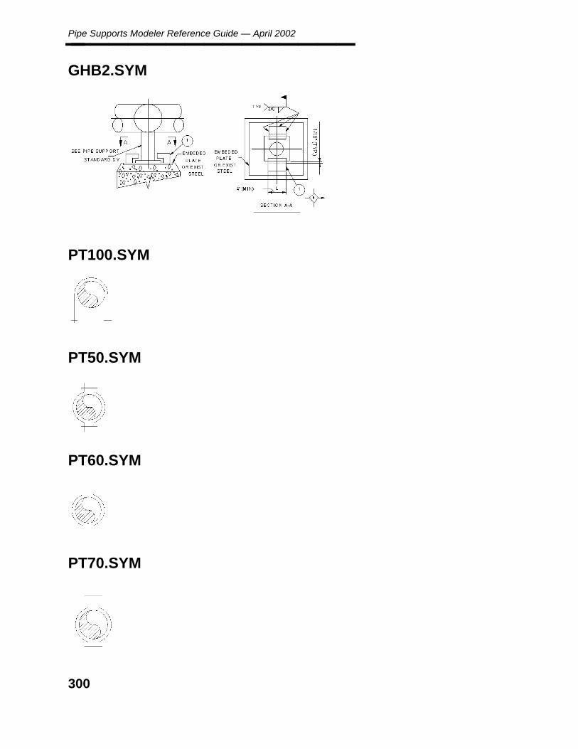
Pipe Supports Modeler Reference Guide — April 2002________________
GHB2.SYM
PT100.SYM
PT50.SYM
PT60.SYM
PT70.SYM
300

D. S
ymb
ols
Appendix D: Delivered Pipe Support Symbols________________
PT80.SYM
RHB1P1.SYM
RHB1P2.SYM
301
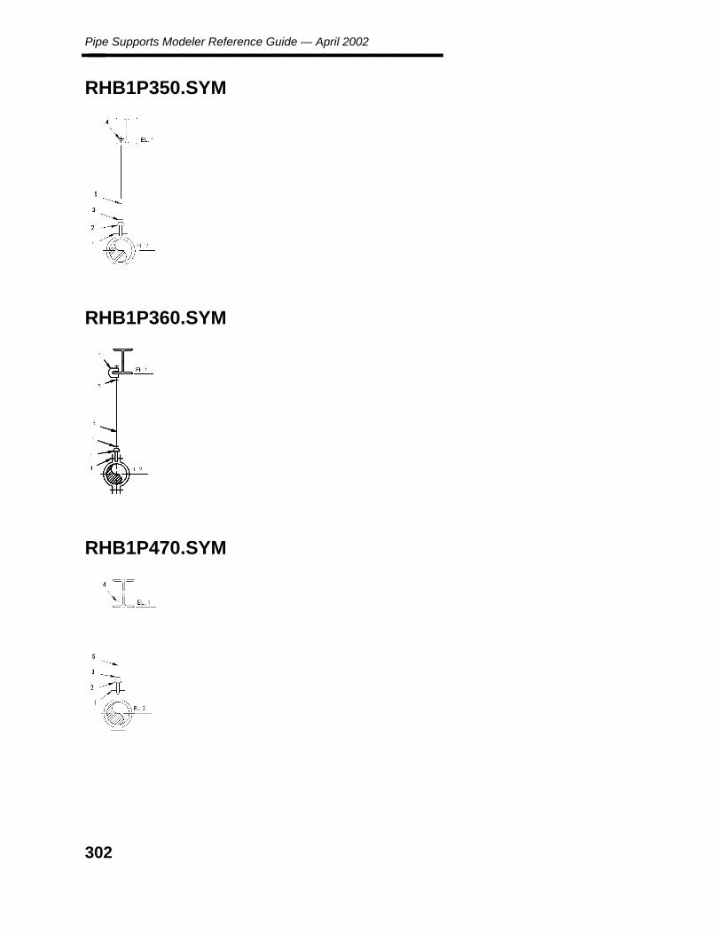
Pipe Supports Modeler Reference Guide — April 2002________________
RHB1P350.SYM
RHB1P360.SYM
RHB1P470.SYM
302

D. S
ymb
ols
Appendix D: Delivered Pipe Support Symbols________________
RHB1P480.SYM
RHB1P5.SYM
RHB1P6.SYM
303
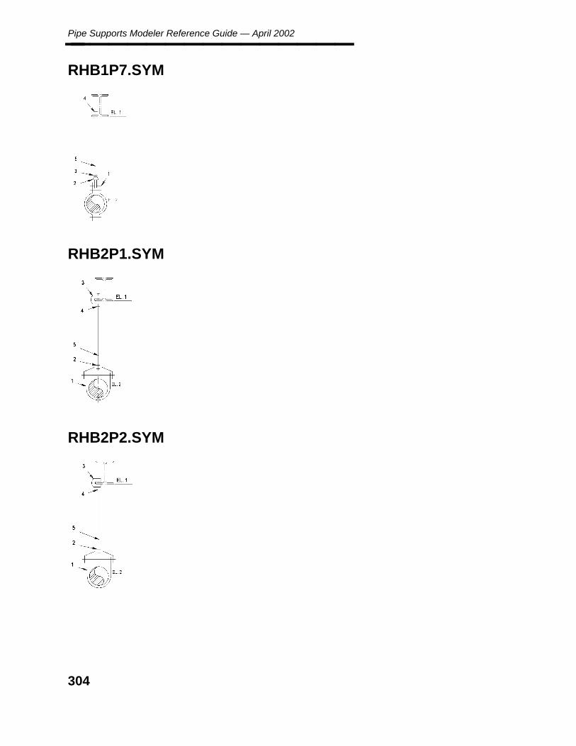
Pipe Supports Modeler Reference Guide — April 2002________________
RHB1P7.SYM
RHB2P1.SYM
RHB2P2.SYM
304
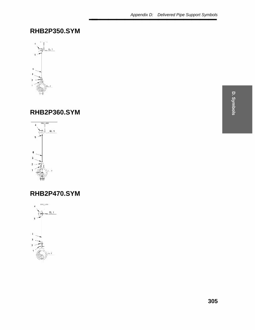
D. S
ymb
ols
Appendix D: Delivered Pipe Support Symbols________________
RHB2P350.SYM
RHB2P360.SYM
RHB2P470.SYM
305

Pipe Supports Modeler Reference Guide — April 2002________________
RHB2P480.SYM
RHB2P5.SYM
RHB2P6.SYM
306

D. S
ymb
ols
Appendix D: Delivered Pipe Support Symbols________________
RHB2P7.SYM
RHB3P1.SYM
RHB3P2.SYM
307
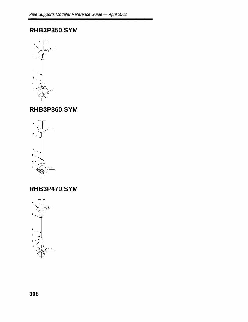
Pipe Supports Modeler Reference Guide — April 2002________________
RHB3P350.SYM
RHB3P360.SYM
RHB3P470.SYM
308
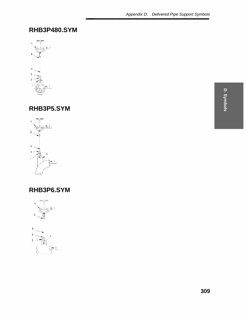
D. S
ymb
ols
Appendix D: Delivered Pipe Support Symbols________________
RHB3P480.SYM
RHB3P5.SYM
RHB3P6.SYM
309
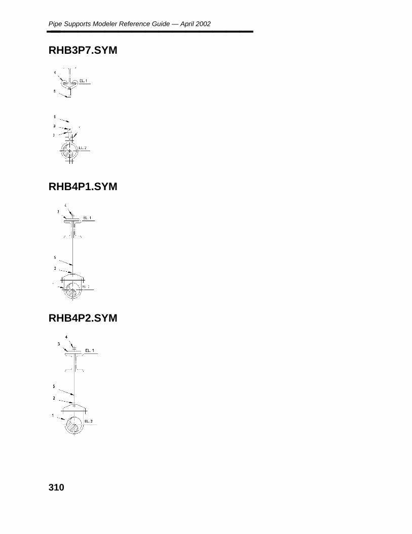
Pipe Supports Modeler Reference Guide — April 2002________________
RHB3P7.SYM
RHB4P1.SYM
RHB4P2.SYM
310

D. S
ymb
ols
Appendix D: Delivered Pipe Support Symbols________________
RHB4P350.SYM
RHB4P360.SYM
RHB4P470.SYM
311

Pipe Supports Modeler Reference Guide — April 2002________________
RHB4P480.SYM
RHB4P5.SYM
RHB4P6.SYM
312

D. S
ymb
ols
Appendix D: Delivered Pipe Support Symbols________________
RHB4P7.SYM
RHB5P1.SYM
RHB5P2.SYM
313

Pipe Supports Modeler Reference Guide — April 2002________________
RHB5P350.SYM
RHB5P360.SYM
RHB5P470.SYM
314

D. S
ymb
ols
Appendix D: Delivered Pipe Support Symbols________________
RHB5P480.SYM
RHB5P5.SYM
RHB5P6.SYM
315

Pipe Supports Modeler Reference Guide — April 2002________________
RHB5P7.SYM
RHB6P1.SYM
RHB6P2.SYM
316

D. S
ymb
ols
Appendix D: Delivered Pipe Support Symbols________________
RHB6P350.SYM
RHB6P360.SYM
RHB6P470.SYM
317

Pipe Supports Modeler Reference Guide — April 2002________________
RHB6P480.SYM
RHB6P5.SYM
RHB6P6.SYM
318

D. S
ymb
ols
Appendix D: Delivered Pipe Support Symbols________________
RHB6P7.SYM
RHC5P1.SYM
RHC5P2.SYM
319

Pipe Supports Modeler Reference Guide — April 2002________________
RHC5P350.SYM
RHC5P360.SYM
RHC5P470.SYM
320

D. S
ymb
ols
Appendix D: Delivered Pipe Support Symbols________________
RHC5P480.SYM
RHC5P5.SYM
RHC5P6.SYM
321
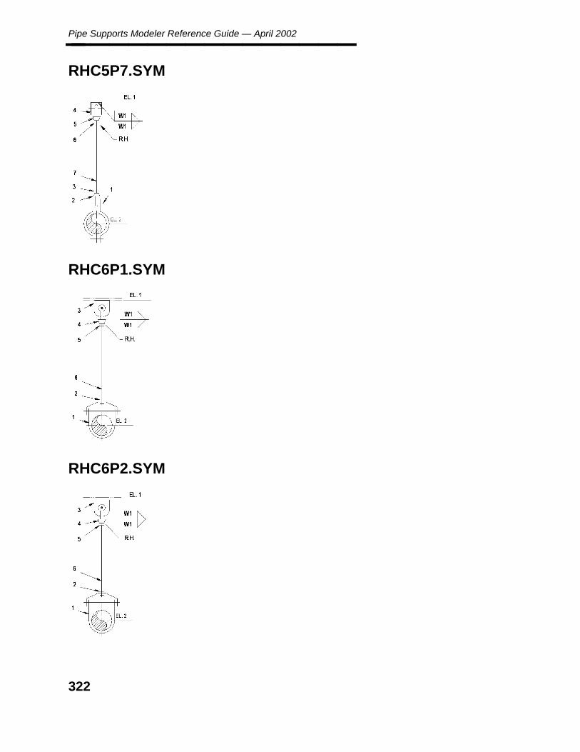
Pipe Supports Modeler Reference Guide — April 2002________________
RHC5P7.SYM
RHC6P1.SYM
RHC6P2.SYM
322

D. S
ymb
ols
Appendix D: Delivered Pipe Support Symbols________________
RHC6P350.SYM
RHC6P360.SYM
RHC6P470.SYM
323

Pipe Supports Modeler Reference Guide — April 2002________________
RHC6P480.SYM
RHC6P5.SYM
RHC6P6.SYM
324

D. S
ymb
ols
Appendix D: Delivered Pipe Support Symbols________________
RHC6P7.SYM
RHD5P1.SYM
RHD5P2.SYM
325

Pipe Supports Modeler Reference Guide — April 2002________________
RHD5P350.SYM
RHD5P360.SYM
RHD5P470.SYM
326

D. S
ymb
ols
Appendix D: Delivered Pipe Support Symbols________________
RHD5P480.SYM
RHD5P5.SYM
RHD5P6.SYM
327
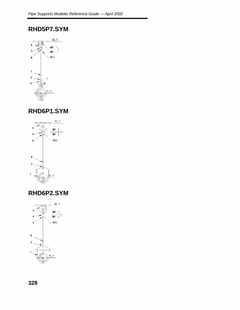
Pipe Supports Modeler Reference Guide — April 2002________________
RHD5P7.SYM
RHD6P1.SYM
RHD6P2.SYM
328

D. S
ymb
ols
Appendix D: Delivered Pipe Support Symbols________________
RHD6P350.SYM
RHD6P360.SYM
RHD6P470.SYM
329

Pipe Supports Modeler Reference Guide — April 2002________________
RHD6P480.SYM
RHD6P5.SYM
RHD6P6.SYM
330

D. S
ymb
ols
Appendix D: Delivered Pipe Support Symbols________________
RHD6P7.SYM
SC.SYM
331
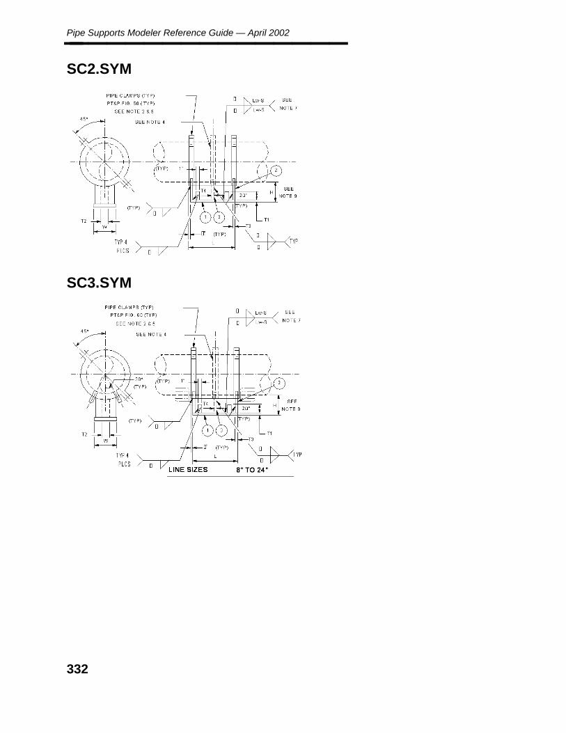
Pipe Supports Modeler Reference Guide — April 2002________________
SC2.SYM
SC3.SYM
332

D. S
ymb
ols
Appendix D: Delivered Pipe Support Symbols________________
SCAD.SYM
SCEH.SYM
333
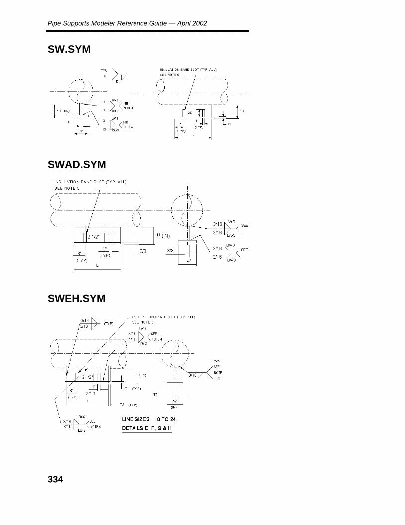
Pipe Supports Modeler Reference Guide — April 2002________________
SW.SYM
SWAD.SYM
SWEH.SYM
334
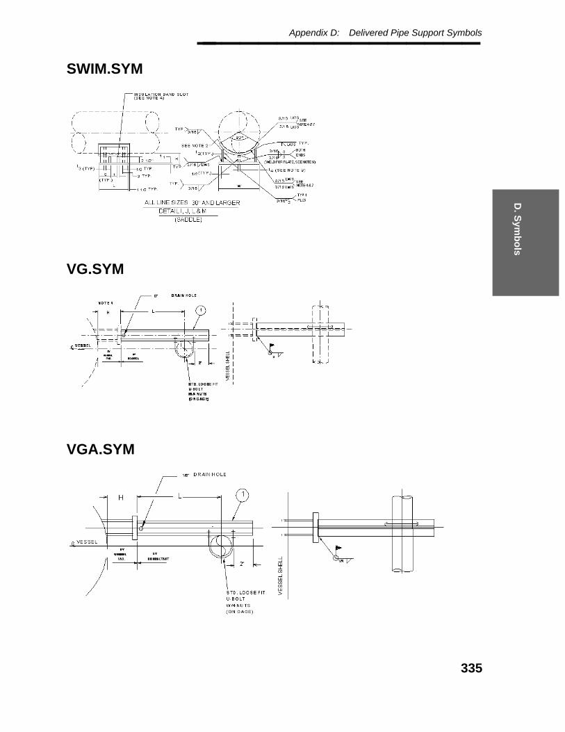
D. S
ymb
ols
Appendix D: Delivered Pipe Support Symbols________________
SWIM.SYM
VG.SYM
VGA.SYM
335
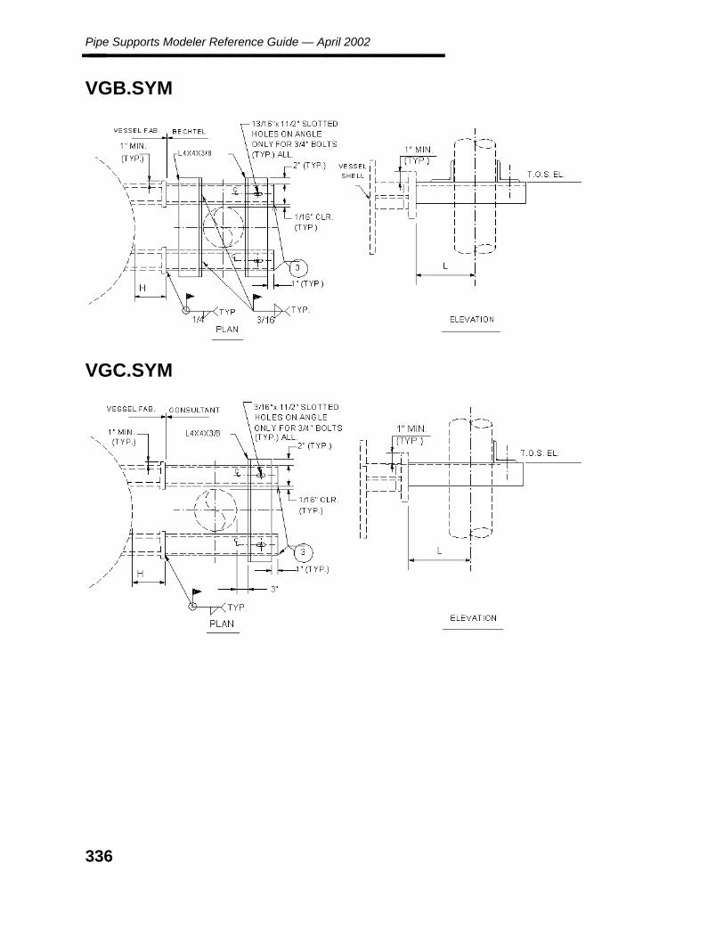
Pipe Supports Modeler Reference Guide — April 2002________________
VGB.SYM
VGC.SYM
336

D. S
ymb
ols
Appendix D: Delivered Pipe Support Symbols________________
VS.SYM
VSA.SYM
337
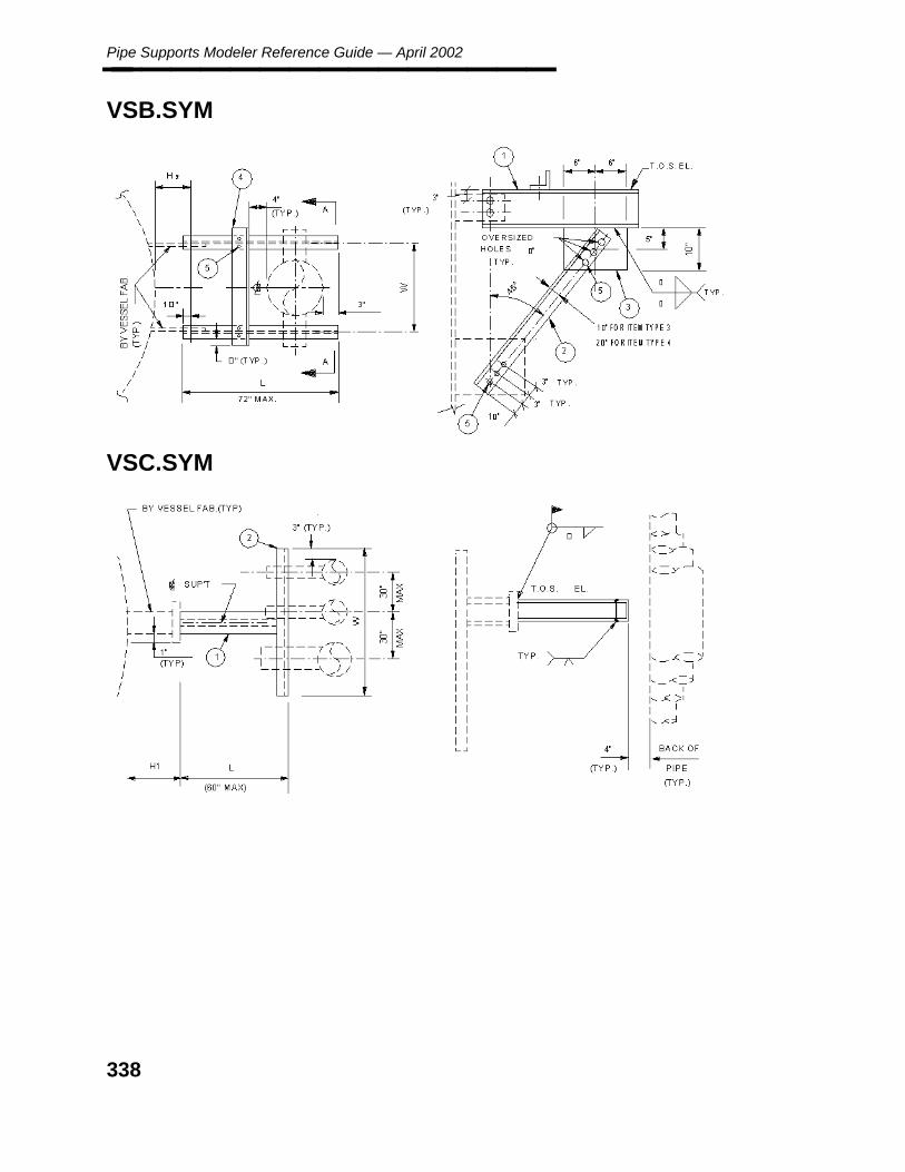
Pipe Supports Modeler Reference Guide — April 2002________________
VSB.SYM
VSC.SYM
338

D. S
ymb
ols
Appendix D: Delivered Pipe Support Symbols________________
VSD.SYM
VSE.SYM
339

Pipe Supports Modeler Reference Guide — April 2002________________
VSF.SYM
VSG.SYM
340

Glo
ssary
Glossary________________
Glossary
absolute path name The sequence of directories, beginning with the root directory (/) thatlocates a file. See also path name and relative path name.
active depth The plane in a 3-D design upon which you can place elements and performmanipulations.
active process The process which is displayed in the Process ID field; it controls themessage fields, the menus, and the keyboard. The active process has ahighlighted window icon strip.
application software Software designed to meet specific needs, unlike system software whichruns other software.
batch processing A method of processing data which collects a series of operations into agroup (or ‘‘batch’’) and executes the group in a continuous stream withoutuser intervention.
batch queue A queue, or channel for moving requests, created through NQS. A batchqueue handles scheduling for processes submitted through the Batchoptions screen menu.
branch point A point on a pipeline which separates piping segments so that they can beassigned different segment parameters. A branch point allows forplacement of branch components.
cancel button The button located in the upper right corner of a form containing a red X orthe word cancel. Select the cancel button to exit the form or option.
cell A permanent association of elements that can be stored and placed as agroup, and then manipulated as individual elements.
character A column data type that stores alphanumeric character data.
client In network operations, a node which accesses data or performs a function onthe remote resource (usually a server). All network operations (database,NFS, NQS) between two or more nodes establish a client/serverrelationship.
column An attribute of a database table. A group of columns defines a table in adatabase.
command Instructions from the user to perform a function on specified data.
confirm button A button that appears in the upper right corner of a form and contains agreen check mark or the word confirm. Select the confirm button to initiatea specified option.
341
Pipe Supports Modeler Reference Guide — April 2002________________
coordinate The location of a point along the X, Y, or Z axis.
coordinate system A geometric relation used to denote the location of points in the designcube. The most common coordinate system is the rectangular coordinatesystem, whereby points are located by traversing the X, Y, and Z axes of thedesign cube. Normally, coordinate systems have their origin defined as0,0,0, though this is not required. Other coordinate systems are used to moreeasily express the coordinates of specific geometric entities. For example,you can use a spherical coordinate system to help define points on a sphere,and you can use a cylindrical coordinate system to help define points on acylinder.
coordinates An ordered set of absolute or relative data values that specify a location in acoordinate system.
core files The image files written by System V for a number of reasons, the mostcommon of which are memory violations, illegal instructions, bus errors,and user-generated quit signals.
cursor The pointer that the user moves on the screen to indicate an item or area.
data button The mouse button used to place data points and tentative points, to acceptpreviously selected elements, and to select commands from forms andmenus.
data entry field The field on a screen used to accept user-supplied data. Also known askey-in field.
data point A point placed by pressing the data button on the mouse. Data points selectcommands from the panel menus and Menu Bar, place elements, identifyand accept elements, and activate windows and perform windowmanipulations.
database A collection of comprehensive informational files having predeterminedstructure and organization that can then be communicated, interpreted, orprocessed by a specific program.
database table The part of the database that is made of rows and columns and containsinformation about the project and design elements.
default The predetermined value of a parameter that is automatically supplied bythe system or program whenever a value is not specified by the user.
delete To remove, destroy, eliminate, or erase.
delimiter A separating mark or space; a character or sequence of contiguouscharacters that mark the end of a string of characters.
device A nonaddressable component of a network, that is, a component onto whicha user cannot log, for example, tape drive, disk drive, and floppy disk.
342

Glo
ssary
Glossary________________
directory A file that contains the names of other files.
display-list box A small box with horizontal dashes located at the end of a form key-in field.When selected, a list of the data available for that field is displayed. Inputcan then be selected from the list with a data point instead of keying in theinformation.
domain The set of acceptable values for a value within a component.
dragging Another term for the dynamic function that attaches the cursor to an elementso you can see it move.
easting A term used in plane surveying that describes an east, or positive, differencein longitude.
entity An object (project, drawing, element, and so forth.) of interest about whichinformation is stored; a relational database table.
envelope file See interference envelope.
file specification A UNIX path name that tells the system where to locate a file.
filename A user-defined name given to an interactively created file. The name shouldbe relevant to the contents of the file.
form An interface or screen menu designed with the I/FORMS product. Becausemany of the screen menus in the application software are built withI/FORMS, you must have the FORMS_S product on your workstation.
full path name The name of the entire path or directory hierarchy to a file, including the filename. See also relative path name.
gadget A portion of a form, such as a button, a field, or a checklist, that responds toinformation. Gadgets can display default values or act as data entry areas.
header The first items of information in a file which precede any actual data. Theheader contains information on the structure and contents of the file.
hierarchy A classified structure with superiors (roots) and subordinates (dependents)for grouping files or commands.
icon A pictorial representation or image; a symbol that graphically identifies acommand.
Informix A relational database management system supported by RIS.
Ingres A relational database management system supported by RIS.
interference envelope An equipment modeling primitive or parametric component that is used inconjunction with or instead of model graphics for interference checking.Interference envelopes are given different levels and display symbology todistinguish them from primitives.
343

Pipe Supports Modeler Reference Guide — April 2002________________
invert elevation The lowest point on the internal diameter of the pipe.
isometric Relating to or being a drafting system characterized by three equal axes atright angles; a view in which the horizontal lines of an element are drawn atan angle to the horizontal and all verticals are projected at an angle from thebase.
key An attribute (column) in a table which is chosen as the access vehicle toindividual rows of the table.
key-in field The field on a screen used to accept user-supplied data. Also known as adata entry field.
keypoint A point on an element, including vertices, to which you can snap.
keyword A word recognized by the software that provides access to a certainfunction.
menubar The strip at the top of the screen that contains icons for selectingcommands.
message area The area that appears in the MicroStation Command Window when you areworking in a design file. It is divided into the Command Status field, theCurrent Command field, the Prompt field, and the Key-in field.
model A graphic representation or schema.
network An interconnection of host computers and workstations that enables them toshare data and control. The term network can mean the devices that connectthe system, or it can mean the connected system.
NFS Network File System, the system that provides access to data that isdistributed among machines through an interconnection of host computersand workstations. NFS allows you to mount a remote resource to your localworkstation so you can access the data as though it were local. NFS isusually used to access centralized data on a server.
node Any addressable device (such as a workstation or a server) that is connectedto a network. The network enables the connected nodes to share data andsystem control.
node address The hard-wired Ethernet address assigned to each node when it ismanufactured. It is necessary for each node to identify and communicatewith another node in the network.
node name A name, or alias, that can be assigned to the node address of a device on anetwork.
northing A term used to describe a north coordinate location in the plant coordinatesystem.
344

Glo
ssary
Glossary________________
nozzle A special equipment modeling primitive that contains the connection pointto piping. This point does NOT include a gasket allowance, but ratherrepresents the face-of-flange coordinate.
NQS Network Queuing System, the software package that allows you to definenetwork-wide batch and device queues. Use of NQS involves setting uplocal resource queues on the system(s) where the resources reside andsetting up ‘‘pipe queues’’ on the systems that are to have access to theresources.
Oracle A relational database management system supported by RIS.
origin In coordinate geometry, the point where the x, y, and z-axes intersect.
origin point The point at which the coordinate system is placed.
orthogonal view A view which is a projection of the model onto a plane along lines whichare orthogonal to the plane.
parameter A property whose value determines the characteristics or behavior ofsomething.
path A sequence of directories leading to a file or a sequence of menus leading toa command.
path name The sequence of directories leading to a file. See also absolute path nameand relative path name.
PDS Plant Design System
pipe queue A controlled channel for moving requests to batch or device queues onremote systems and for receiving status and/or data in response.
place data point To identify a specific element, or indicate a specific point in the design file.
plane A spatial element in geometry that may or may not have a boundary, but islevel, having no elevations or depressions, and is three-dimensional.
RDB Reference Database.
reference database A collection of reference data containing information relative to industrydesign codes, vendor’s catalog data, job specifications, commodity libraries,graphics symbology, label descriptions, report formats and otherinformation of a similar manner.
relative path name The sequence of directories leading from the current directory to a particularfile. See also path name and absolute path name.
rotate To turn; to change the angular orientation; to transform by revolution abouta specific axis.
345
Pipe Supports Modeler Reference Guide — April 2002________________
row A unit of related information in a table. One collection of column values fora table.
rubberbanding The animation dynamic that enables you to specify the position of a datapoint while the element changes as you move the cursor.
schema A description of the overall structure of the rulebase or database.
schema file A file that outlines the overall logical structure of a rule base or a database.
server In network operations, the node which maintains common data or performsa common task needed by clients. All network operations (database, NFS,NQS) between two or more nodes establish a client/server relationship.
Structured QueryLanguage SQL
Language developed by IBM for creating, modifying, and queryingrelational databases.
style The symbology of an element such as continuous dashes, dash-dot, solid,and so forth.
surface The skin of a three-dimensional geometric element.
symbology The display style of an element, including color, style, and weight.
table A collection of data for quick reference, either stored in sequential locationsin memory or printed as an array of rows and columns of data items of thesame type.
toggle To switch; to change between two alternatives.
user name A name that provides access to an account on the system.
values Data, either entered by the user or determined by the software, that arestored in an attribute.
variable A quantity that may assume any one of a set of values.
vector A quantity possessing both magnitude and direction, generally representedas a line. Vectors can be manipulated geometrically and are represented asa coordinate triple (x,y,z).
view The defined area of vision on a screen. A view allows you to see aprescribed volume of the design cube. Views are created with their own x,y, and z axes. The x,y plane of the view is parallel to the screen, while thez-axis can be thought of as coming straight out of the view towards you.The view axes maintain this relationship regardless of the rotation withrespect to the design cube. See also active depth.
virtual memory External memory for a computer that can be used as if it were an extensionof the computer’s internal memory. The software uses virtual memory tostore data. This means that unneeded files and data, stay on the disk untilthey are called for. Because the internal processing memory stores aminimal amount of data, the software can perform processing more quickly.
346

Glo
ssary
Glossary________________
working directory The directory from which you are accessing files.
347

Pipe Supports Modeler Reference Guide — April 2002________________
348

Ind
ex
Index________________
Index
Aactive
color 78style 80weight 79
analyzecommands 83data 83
designcheck review 92review 84
piping clashcheck 90review 87
applicationscommand 103
attributereview 70
attributesrevise 58table240 23
automationSmartSketch drawing 125
Cchecklist
setup 19clash check 90command
applications 103exit 122help 121
commandselement 100file 97setting 101user 102view 96
commodityreference
data 24copy
pipe support 50create
drawing seed files 135SmartSketch drawing 136
create (continued)support
gang 63support gang 63symbol 137
Ddata
commodityreference 24
data flowpipe supports 18
deletedrawing 112pipe support 68
deliveredforms 259pipe support symbols 275tutorial definition files 259
description datamaterial
reference 26support material 30
designcheck
review 92checker 92review 84
details iconview 120
displayfield weld 81isometric drawing limit 81only labels 81report 73
documentorganization 10print 110purpose 9
drawingautomation
SmartSketch 125create seed files 135create SmartSketch drawing 136delete 112formatted text 131
349

Pipe Supports Modeler Reference Guide — April 2002________________ drawing (continued)
generate 116layout customization 133layout symbols 129support
report 109title block 130view 115
drawingsshow 111
Eedit
SmartSketch symbol 138SmartSketch symbol properties 140
elementcommands 100
exitcommand 122
explorerpipe support 105
Ffile
commands 97form
placesupport 38
formatted text 131forms
delivered 259
Ggenerate
drawing 116group
reference data 22support 60
Hhelp
command 121
Iicon
viewdetails 120large 117list 119small 118
interference check 90
Kkey plan
support location 132
Llabels
display only 81large icon
view 117library
symbolopen 142
list iconview 119
logical supportplace 55
Mmanipulate
SmartSketch symbol 141material reference
descriptiondata 26
modeldata
review 69attributes 70nozzle data 72report 73
modelerpipe support 35, 107
movesupport 66
Nnozzle
data 72
Oopen
symbol library 142
Ppalette
placesupport 37
physicalpipe support
place 53
350

Ind
ex
Index________________ pipe support 15
delete 68drawing
formatted text 131explorer 105forms
delivered 259location key plan 132modeler 35, 107revise 57symbols 127
delivered 275standard support 128
pipingclash
check 90review 87
placelogical support 55physical
pipe support 53support
form 38symbol 143
point in space command 41point on pipe command 42print
document 110properties 114
RRDB
review report 93reference
commoditydata 24
datapipe support 21
materialdescription
data 26viewer 108
reference datapipe support
group 22support material 27
reportsupport/drawing 109
reportsdisplay 73
restore permanent symbology 82review
attributes 70data 69nozzle data 72RDB
report 93report 73temporary symbology 76
reviseattributes 58pipe support 57
Sseed files
drawing 135settings
commands 101setup
checklist 19show
supports 113small icon
view 118SmartSketch
create drawing 136create symbol 137drawing
automation 125edit symbol 138edit symbol properties 140manipulate symbol 141open symbol library 142place symbol 143symbols
introduction 123view
drawing 115specifics
pipe supports 17standard support graphic symbols 128support 36
copy 50drawing
report 109group 60move 66place
palette 37support gang
create 63
351
Pipe Supports Modeler Reference Guide — April 2002________________ support location key plan 132support material
description data 30reference data 27
supportsshow 113
symbolcreate 137edit 138edit properties 140library
open 142manipulate 141place 143
symbolsdelivered 275drawing layout 129drawing title block 130pipe support 127SmartSketch
introduction 123standard support 128
Ttable 240
attributes 23temporary symbology 76
activecolor 78line style 80weight 79
display only labels 81restore permanent symbology 82
title block symbols 130tutorial definition files
delivered 259typefaces 11
Uuser
commands 102user-interface definition
formtable 33
Vview
commands 96drawing 115
viewerreference 108
352
Pipe Supports Modeler Reference Guide Addendum March 2007 DPDS3-PB-2000026D For PDS 8.0 SE This document supplements DPDS3-PB-2000026C.

Pipe Supports Modeler Reference Guide – March 2007
354
Table of Contents Pipe Support Explorer (replaces 4.0)........................................................................355 Open Symbol Files (replaces 4.2).............................................................................357 Show Property (replaces 4.8)....................................................................................358 Edit Drawing (replaces 4.9)......................................................................................359 Generate Drawing (replaces 4.10) ............................................................................360

355
Pipe Support Explorer (replaces 4.0) Note: The information in this section supersedes the information in the corresponding section of previous versions of the Pipe Supports Modeler Reference Guide (pp 105-106 in the PDS 7.1 version of the document).
The following information has been modified:
• Removed Reference Viewer, Show Drawings, and View Drawing command descriptions.
• Added Projects Listing and Open Symbol Files command description.
• Changed Properties command name to Show Property. See the following text for details.
The Pipe Support Explorer provides a Windows look and feel interface, that allows creation of Pipe Support construction drawings using the SmartSketch Automation. The Pipe Support Explorer interface consists of two windows for easy navigation of the Pipe Support design data within the PDS project environment. The left window portion is the Project TreeView that presents the PDS project environment data (Project, Area and Model, etc.) in hierarchy tree. The right window portion is a ListView window that displays the Pipe Support Design data or the Pipe Support Construction Drawing data.
Option Descriptions Projects Listing — Displays all available projects in the List View.
Pipe Supports Modeler — Used to switch to the Pipe Supports Modeler application.
Open Symbol Files — Used to open symbols in SmartSketch.
Support/Drawing Report — Displays pipe supports or drawings. This option is used to create the ASCII report from the explorer ListView window.
Pipe Supports Modeler Reference Guide – March 2007
356
Show Property — Provides attribute and value information associated with the selected drawing or pipe support.
Edit Drawing — Used to open the selected drawing in SmartSketch.
Print Document — Used to print the selected support drawing document using the default printer.
Delete Drawing — Used to delete the pipe support construction drawing from the project directory. The database occurrence is also deleted from the project database.
Show Supports — Used to list the Pipe Supports design data based on the selected project, area and model.
Generate Drawing — Used to generate a new SmartSketch automation.
Large Icon View — Used to display project, model, drawing or pipe support icons in large format.
Small Icon View — Used to display project, model, drawing or pipe support icons in small format.
List View — Used to display project, model, drawing or pipe support icons in small icon format.
Details View — Used to display project, model, drawing or pipe support icons in small icon format with attribute details.
Intergraph Web Sites — Opens the Intergraph web site in a browser window.
Help — Used to display on-line information about pipe support commands.
Exit — Used to exit the PDS Pipe Support Explorer software.
Operating Sequence 1. Select the Pipe Support Explorer icon.
The Pipe Support Explorer menu is displayed.
2. Select a project by double-clicking on a project icon or select from the Select Project pull-down list.
The project is attached and initialized.

357
Open Symbol Files (replaces 4.2) Note: The information in this section supersedes the information in the corresponding section of previous versions of the Pipe Supports Modeler Reference Guide (p. 116 in the PDS 7.1 version of the document).
The following information has been modified:
• Changed Reference Viewer command name to Open Symbol Files • Updated topic text
See the following text for details.
The Open Symbol Files option is used to open the selected symbol in SmartSketch.
Operating Sequence 1. Select the Open Symbol Files option.
2. Select the symbol file to open.
3. Click Open.
The selected symbol file opens in SmartSketch.

Pipe Supports Modeler Reference Guide – March 2007
358
Show Property (replaces 4.8) Note: The information in this section supersedes the information in the corresponding section of previous versions of the Pipe Supports Modeler Reference Guide (p. 114 in the PDS 7.1 version of the document).
The following information has been modified:
• Changed command name from Properties to Show Property • Updated Operating Sequence
See the following text for details.
The Show Property option provides attribute and value information associated with the selected drawing or pipe support.
Operating Sequence 1. Select the drawing or pipe support.
Select the drawing number or pipe support for which to show properties.
The selected drawing number or pipe support is highlighted.
2. Select the Show Property option.
Select the Show Property icon from the PDS Pipe Support Explorer menu.
The Property screen is displayed providing attribute and value information.
359
Edit Drawing (replaces 4.9) Note: The information in this section supersedes the information in the corresponding section of previous versions of the Pipe Supports Modeler Reference Guide (p. 115 in the PDS 7.1 version of the document).
The following information has been added:
• Changed command name from View Drawing to Edit Drawing • Updated Operating Sequence
See the following text for details.
The Edit Drawing option is used to open a drawing using SmartSketch.
Operating Sequence 1. Select the drawing to edit.
Select the drawing number to edit.
The selected drawing number is highlighted.
2. Select the Edit Drawing option.
Select the Edit Drawing icon from the PDS Pipe Support Explorer menu.
The drawing opens in SmartSketch.
Pipe Supports Modeler Reference Guide – March 2007
360
Generate Drawing (replaces 4.10) Note: The information in this section supersedes the information in the corresponding section of previous versions of the Pipe Supports Modeler Reference Guide (p. 116 in the PDS 7.1 version of the document).
The following information has been added:
• Note regarding SmartSketch versions See the following text for details.
The Generate Drawing option is used to generate a new SmartSketch drawing for a pipe support.
Note: SmartSketch must be loaded to use this option.
Important: PDS uses SmartSketch 5.0 to generate pipe support drawings through the Pipe Support Explorer module. If you want to upgrade a PDS project to version 8.0, you will need to update all your SmartSketch symbols to version 5.0.
To upgrade SmartSketch symbols from version 3.0 to version 5.0, you must open the symbols in SmartSketch 4.0 and save them, and then open them in SmartSketch 5.0 and save them.
Pipe Supports Explorer incorporates the functionality of SmartSketch as the tool to generate drawings to produce a standard support detailed drawing.
Operating Sequence 1. Select the Show Supports option.
Select the Show Supports icon from the PDS Pipe Support Explorer menu.
The message is displayed to indicate data is being loaded. A listing of pipe supports is displayed by Tag Number.
2. Select Item
Select the Pipe Support Item from the Support Data window.
3. Select the Generate Drawing option.
Select the Generate Drawing icon.
The drawing is generated using SmartSketch.

361
Index drawings
editing, 359 generating, 360
Edit Drawing, 359 Generate Drawing, 360 Open Symbol Files, 357
Pipe Support Explorer, 355 properties
displaying, 358 Show Property, 358 symbol files
opening, 357

Pipe Supports Modeler Reference Guide – March 2007
362