submittal 0240y-m58-m54 support - jay r. smith mfg co. · pdf filed d face plate face plate...
TRANSCRIPT
REV. DATE DESCRIPTION BY CKD. BY
WEIGHTPOUNDS
VOLUMECUBIC FEET
FIGURE NUMBER
LOCATION
FIG
UR
EN
UM
BE
R
DIM
EN
SIO
NS
AR
E S
UB
JEC
T T
O M
AN
UFA
CT
UR
ER
S T
OLE
RA
NC
E A
ND
CH
AN
GE
WIT
HO
UT
NO
TIC
EW
E C
AN
AS
SU
ME
NO
RE
SP
ON
SIB
ILIT
Y F
OR
US
E O
F S
UP
ER
SE
DE
D O
R V
OID
DAT
A
DR
AW
N B
Y:
CH
EC
KE
D B
Y:
AP
PR
OV
ED
BY
:D
ATE
:S
CA
LE:
SIZ
E AD
RA
WIN
G N
UM
BE
R
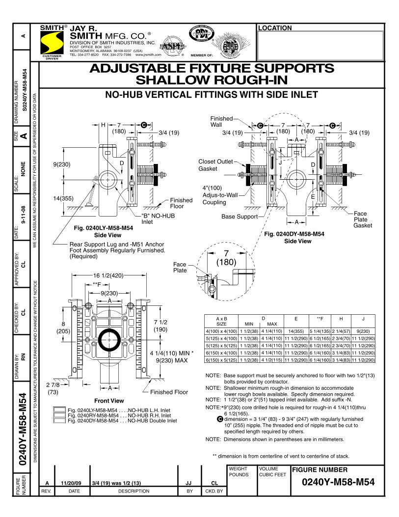
Fig. 0240LY-M58-M54 . . . .NO-HUB L.H. InletFig. 0240RY-M58-M54 . . . NO-HUB R.H. InletFig. 0240DY-M58-M54 . . . NO-HUB Double Inlet
NOTE: Base support must be securely anchored to floor with two 1/2"(13) bolts provided by contractor.NOTE: Shallower minimum rough-in dimension to accommodate lower rough bowls available. Specify dimension required.NOTE: 1 1/2"(38) or 2"(51) tapped inlet available. Add suffix -N.
NOTE: 9"(230) core drilled hole is required for rough-in 4 1/4(110)thru 6 1/2(165). dimension = 3 1/4” (83) - 9 3/4” (247) with regularly furnished 10” (255) nipple. The threaded end of nipple must be cut to specified length required by others.
C
*
** dimension is from centerline of vent to centerline of stack.
H 7(180)
ADJUSTABLE FIXTURE SUPPORTSSHALLOW ROUGH-IN
NO-HUB VERTICAL FITTINGS WITH SIDE INLET
14(355)
"B" NO-HUBInlet
C
Fig. 0240LY-M58-M54Side View
C C
A
A
FinishedWall
4"(100)Adjus-to-WallCoupling
Base Support
Fig. 0240DY-M58-M54Side View
A
Front View
16 1/2(420)
9(230)A
8(205)
2 7/8(73)
7 1/2(190)
4 1/4(110) MIN *9(230) MAX
Finished Floor
NO
NE
E
D D
Face Plate
Face Plate
Gasket
NOTE: Dimensions shown in parentheses are in millimeters.
Rear Support Lug and -M51 AnchorFoot Assembly Regularly Furnished.(Required)
Closet Outlet Gasket
0240
Y-M
58-M
54
0240Y-M58-M54
9-11
-08
RN
CL
CL
AS
0240
Y-M
58-M
54
9(230)
Finished Floor
7(180)
7(180)
7(180)
A x BSIZE
4(100) x 4(100)
5(125) x 4(100)
5(125) x 5(125)
6(150) x 4(100)
6(150) x 5(125)
MIN
1 1/2(38)
1 1/2(38)
1 1/2(38)
1 1/2(38)
1 1/2(38)
MAX
4 1/4(110)
4 1/4(110)
4 1/4(110)
4 1/4(110)
4 1/2(115)
E
14(355)
11 1/2(290)
11 1/2(290)
11 1/2(290)
11 1/2(290)
**F
5 1/4(135)
6 1/2(165)
6 1/2(165)
6 1/4(160)
6 1/4(160)
H
2 1/4(57)
2 3/4(70)
2 3/4(70)
3 1/4(83)
3 1/4(83)
J
9(230)
11 1/2(290)
11 1/2(290)
11 1/2(290)
11 1/2(290)
D
**F
J
JAY R.SMITH MFG. CO. ®
DIVISION OF SMITH INDUSTRIES, INC.POST OFFICE BOX 3237MONTGOMERY, ALABAMA 36109-0237 (USA)TEL: 334-277-8520 FAX: 334-272-7396 www.jrsmith.comCUSTOMER
DRIVEN
SMITH®
MEMBER OF:
®
ASPE®
SANITARY
EN G IN E E RINGPrevention Rather Than Cure
3/4 (19) 3/4 (19) 3/4 (19)
A 11/20/09 3/4 (19) was 1/2 (13) JJ CL
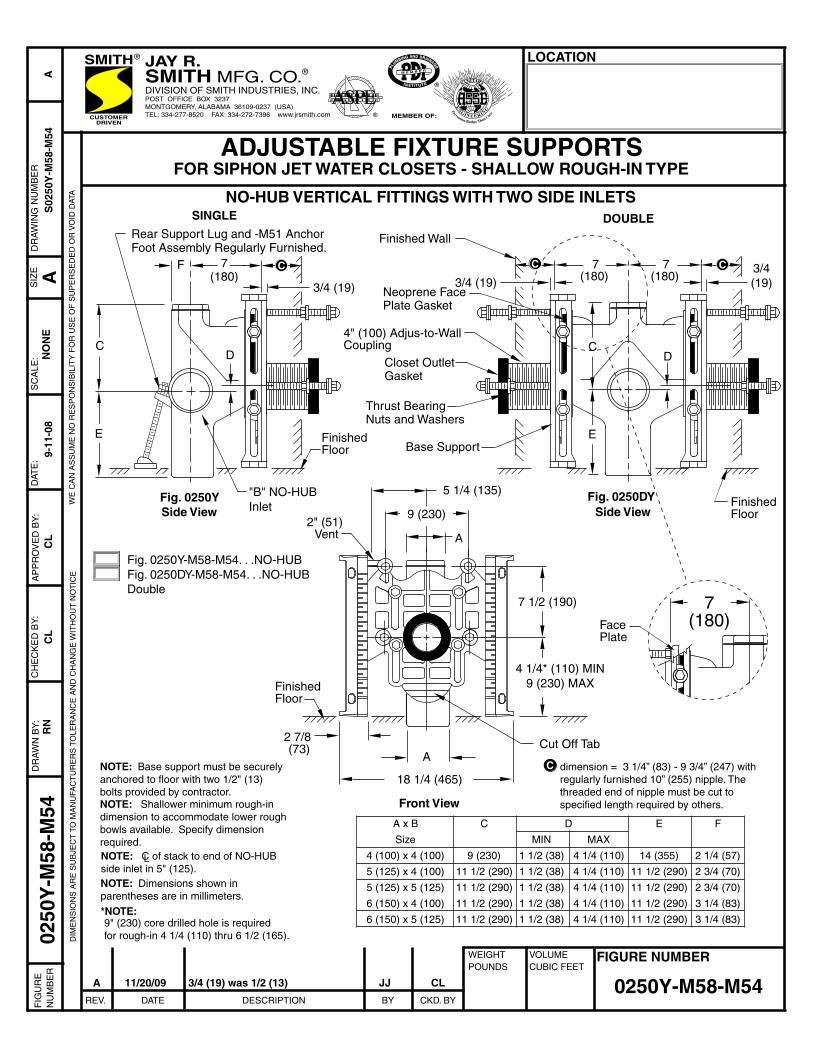
A x B
Size
4 (100) x 4 (100)
5 (125) x 4 (100)
5 (125) x 5 (125)
6 (150) x 4 (100)
6 (150) x 5 (125)
ADJUSTABLE FIXTURE SUPPORTSFOR SIPHON JET WATER CLOSETS - SHALLOW ROUGH-IN TYPE
NO-HUB VERTICAL FITTINGS WITH TWO SIDE INLETS
Fig. 0250Y-M58-M54. . .NO-HUBFig. 0250DY-M58-M54. . .NO-HUB Double
0250Y-M58-M54
0250
Y-M
58-M
54R
N9-
11-0
8N
ON
ES
0250
Y-M
58-M
54
Side View
Front View
DOUBLE
NOTE: Base support must be securelyanchored to floor with two 1/2" (13)bolts provided by contractor.NOTE: Shallower minimum rough-indimension to accommodate lower roughbowls available. Specify dimensionrequired.NOTE: C of stack to end of NO-HUBside inlet in 5" (125).
*NOTE:9" (230) core drilled hole is requiredfor rough-in 4 1/4 (110) thru 6 1/2 (165).
NOTE: Dimensions shown inparentheses are in millimeters.
dimension = 3 1/4” (83) - 9 3/4” (247) with regularly furnished 10” (255) nipple. The threaded end of nipple must be cut to specified length required by others.
C
C
9 (230)
11 1/2 (290)
11 1/2 (290)
11 1/2 (290)
11 1/2 (290)
D
MIN
1 1/2 (38)
1 1/2 (38)
1 1/2 (38)
1 1/2 (38)
1 1/2 (38)
MAX
4 1/4 (110)
4 1/4 (110)
4 1/4 (110)
4 1/4 (110)
4 1/4 (110)
E
14 (355)
11 1/2 (290)
11 1/2 (290)
11 1/2 (290)
11 1/2 (290)
F
2 1/4 (57)
2 3/4 (70)
2 3/4 (70)
3 1/4 (83)
3 1/4 (83)
CL
AC
L
REV. DATE DESCRIPTION BY CKD. BY
WEIGHTPOUNDS
VOLUMECUBIC FEET
FIGURE NUMBER
LOCATION
FIG
UR
EN
UM
BE
R
DIM
EN
SIO
NS
AR
E S
UB
JEC
T T
O M
AN
UFA
CT
UR
ER
S T
OLE
RA
NC
E A
ND
CH
AN
GE
WIT
HO
UT
NO
TIC
EW
E C
AN
AS
SU
ME
NO
RE
SP
ON
SIB
ILIT
Y F
OR
US
E O
F S
UP
ER
SE
DE
D O
R V
OID
DAT
A
DR
AW
N B
Y:
CH
EC
KE
D B
Y:
AP
PR
OV
ED
BY
:D
ATE
:S
CA
LE:
SIZ
E AD
RA
WIN
G N
UM
BE
R
SINGLE
L
5 1/4 (135)
A
A
2 7/8 (73) Cut Off Tab
2" (51) Vent
18 1/4 (465)
4 1/4* (110) MIN9 (230) MAX
7 1/2 (190)
9 (230)Fig. 0250YSide View
"B" NO-HUBInlet
D
F
Rear Support Lug and -M51 AnchorFoot Assembly Regularly Furnished.
7(180)
C
E
Finished Wall
Neoprene Face Plate Gasket
4" (100) Adjus-to-Wall Coupling
Closet Outlet Gasket
Base Support
Fig. 0250DY
D
Finished Floor
Finished Floor
Finished Floor
7 7(180) (180)
C
E
CC C
7(180)
Thrust BearingNuts and Washers
Face Plate
JAY R.SMITH MFG. CO.®
DIVISION OF SMITH INDUSTRIES, INC.POST OFFICE BOX 3237MONTGOMERY, ALABAMA 36109-0237 (USA)TEL: 334-277-8520 FAX: 334-272-7396 www.jrsmith.comCUSTOMER
DRIVEN
SMITH®
MEMBER OF:
®
ASPE®
SANITARY
EN G IN E E RINGPrevention Rather Than Cure
3/4 (19) 3/4 (19)3/4(19)
A 11/20/09 3/4 (19) was 1/2 (13) JJ CL

dimension = 4" (100) (regularly furnished) consisting of nipple andadjus-to-wall coupling permitting adjustment from 3" (76) min. to 4"(100) max.
The Smith Adjus-to-Wall outlet connection provides adjustment at theface of the wall at the time the fixture is set; thus, compensating forwall construction variations. The C dimension is measured from the frontof the face plate to the finished wall. To properly determine the lengthof nipple required, deduct 1" (25) from the C dimension. When the dimension exceeds 7" (180), the -M40 Wide Pipe Chase Support is recommeded. The Adjus-to-Wall coupling will provide 1/2" (13) horizontal adjustment in either direction with the coupling extended 5/16" (8) past face of the finished wall.
REV. DATE DESCRIPTION BY CKD. BY
WEIGHTPOUNDS
VOLUMECUBIC FEET
FIGURE NUMBER
LOCATIONF
IGU
RE
NU
MB
ER
DIM
EN
SIO
NS
AR
E S
UB
JEC
T T
O M
AN
UFA
CT
UR
ER
S T
OLE
RA
NC
E A
ND
CH
AN
GE
WIT
HO
UT
NO
TIC
EW
E C
AN
AS
SU
ME
NO
RE
SP
ON
SIB
ILIT
Y F
OR
US
E O
F S
UP
ER
SE
DE
D O
R V
OID
DAT
A
DR
AW
N B
Y:
CH
EC
KE
D B
Y:
AP
PR
OV
ED
BY
:D
ATE
:S
CA
LE:
SIZ
E AD
RA
WIN
G N
UM
BE
R
MODIFICATIONS & VARIATIONS
0200/0300 SeriesBack Sheet
0200
/030
0 S
erie
sB
ack
Sh
eet
A 7-1-93 Submittal Update EMB
VG
DC
RJD
2-28
-86
NO
NE
S02
00B
SC
SUFFIX -M12 EXPOSED FLUSH VALVE SUPPLY SUPPORT
Water Closet
Exposed Flush Valve
11 1/2" (290) Standard
4 3/4"(120)
Finished Wall
Bearing Nut &Washer
Face Plate1 1/2 (38)
Closet OutletGasket
Tiling Frame
Fitting
Base Support
SUFFIX -M13 TILING FRAME - POLYSTYRENE
Finished Wall
Gasket
Closet Horn
RECOMMENDED SETTING OF CLOSET OUTLET CONNECTION AND FIXTURE STUDS
A
B
DETAIL A
Finished Wall
Support Stud
YX
1/16" (2)
DETAIL B
ABS Coupling
ABS NippleABS Coupling
2 1/2(64)
Face Plate
Finished WallC
*ABS (Regularly Furnished) other length PVC.
C
C
C
C
C
C
CONCEALED FLUSH VALVES
2 1/4 (57)3 (76)8 (205)9 3/4 (250)11 3/4 (300)14 3/4 (376)17 3/4 (450)
2 1/2 (64)*3 1/4 (83)*8 1/4 (210)10 (255)12 (305)15 (380)18 (455)
NIPPLE LENGTHS AVAILABLE
C
3 1/4 (83)4 (100)9 (230)10 3/4 (275)12 3/4 (325)15 3/4 (400)18 3/4 (475)
LENGTH MIN MAX
10 1/2 (265) MIN16 (405 MAX
BSB 6-1-95 Added Millimeters EMB BS
CLC 12-10-03 Revised Notes RN
DIMENSION - ADJUS-TO-WALL TYPE OUTLET CONNECTION
NOTE: When nipple lengths between3 1/4" (83) and 8 1/4" (210) arespecified, the 8 1/4" (210) nipple will besupplied. Nipple must be cut to specifiedlength by others.
Manufacturers have slight differences in the depth of the closet horn and flange thickness of their closets. Usually the fixture support closetconnection should extend 5/16" (8) beyond face of finished wall (Dimension"R") and the fixture studs 2 1/4" (57) (Dimension "X"). For exact dimensionsplease use the formulas below.
DETAIL A Formula for "R" is: S +1/16" (2) - D = R. S = Depth of closet horn 1/16" (2) = Distance closet is to set away from finished wall. D =1/2" (13) for felt gasket and 3/8" (10) for neoprene gasket. R = Distance coupling should extend beyond finished wall. NOTE: When the fixture is installed, closet gasket must be compressed sufficiently to assure a gas and water-tight seal.
DETAIL B Formula for "X" is: Y + 1/16" (2) + 9/16" (14) = X. Y = Thickness of closet wall flange. 1/16" (2) = Distance closet is to set away from finished wall. X = Distance supporting stud should extend beyond finished wall. NOTE: Bearing nuts and washers must be set to take full loading from the fixture allowing 1/16" (2) clearance between fixture and wall.
1/16" (2) ClearanceBetween Back ofCloset and FinishedWall
NOTE: Dimensions shown inparentheses are in millimeters.
Bearing Nutand Washer
-M40 WATER CLOSET SUPPORTFOR WIDE PIPE CHASE (USE WHEN DIMENSION EXCEEDS 7" (180) )
A concealed flush valve when used witha blowout water closet support will notclear the face plate. Therefore 4 1/2"(115) to 6 1/2" (165) is required fromback of wall to face plate to permit theinstallation of the concealed flush valvepiping.
Provides support and alignment for the supply pipe to an exposed flush valve;must be specified for either 1" (25) copper tube or 1" (25) iron pipe.
JAY R.SMITH MFG. CO.®
DIVISION OF SMITH INDUSTRIES, INC.POST OFFICE BOX 3237MONTGOMERY, ALABAMA 36109-0237 (USA)TEL: 334-277-8520 FAX: 334-272-7396 www.jrsmith.comCUSTOMER
DRIVEN
SMITH®
MEMBER OF:
®
ASPE®
SANITARY
EN G IN E E RINGPrevention Rather Than Cure