studies of carbon nanomaterials based on fullerenes and ...140619/fulltext01.pdf · studies of...
TRANSCRIPT

Studies of carbon nanomaterialsbased on fullerenes and carbon
nanotubes
Agnieszka Iwasiewicz-Wabnig
Umeå 2007
Department of Physics, Umeå University

Department of PhysicsUmeå UniversitySE-901 87 Umeå, Sweden
Copyright c© 2007 by Agnieszka Iwasiewicz-WabnigISBN: 978-91-7264-346-8
Typeset in LATEX usingPrinted by Print & Media, Umeå 2007.

To my Family


Materials based on fullerenes and carbon nanotubes are very muchdifferent from most “traditional” materials, primarily because theyare built from nanosized molecules with highly symmetry-depen-dent properties. Being the subject of a very active research fieldover the last twenty years, carbon nanostructures proved to be in-deed extraordinary. Their splendid mechanical properties attracta great interest among material scientists. Their wide range ofelectrical properties, from ballistic conductors to insulators, makesthem ideal candidates for future, better electronics. The possibili-ties seem to be nearly unlimited, with proposed applications rang-ing from quantum computing to medicine. However, in order tomake it all happen one day, we first need to explore and understandthe physics and chemistry of carbon nanomaterials. This work fo-cuses on production and characterization of materials and struc-tures in which fullerenes and/or carbon nanotubes are the mainingredients, and which can be produced or modified under high-pressure–high-temperature (hp-hT) conditions. Raman and photo-luminescence spectroscopy, X-ray diffraction and scanning probemicroscopy were employed for characterization of the samples. Theresearch presented in this thesis is spread over a rather wide rangeof carbon nanomaterials. To highlight some of the main results –the first hp-hT polymerization of C60 nanorods and the C60-cubanecompound is reported. The polymerization mechanism in the lattercase was identified to be radically different from that in pure C60.The pressure-temperature diagram of C60-cubane is presented. Acomparative study of C60 and C70 peapods under extreme p-T condi-tions reveals how the confinement affects the fullerenes’ ability forpolymerization. Finally, in situ resistance measurements on Rb4C60
under high pressure show that the semiconducting character ofthis material persists at least up to 2 GPa, contradicting earlier re-ports on the existence of an insulator-to-metal transition and pro-viding an insight into conduction mechanisms in this anomalousintercalated compound.


Sammanfattning
KOLNANOMATERIAL BASERADE PÅ FULLERENER OCH KOLNANORÖR
Material baserade på fullerener och kolnanorör skiljer sig avsevärtfrån de flesta "traditionella" material, i första hand därför att debyggs upp av nanometerstora molekyler med starkt symmetribero-ende egenskaper. Tjugo år av intensiva studier har visat att kol-nanostrukturer verkligen är extraordinära. Deras utmärkta meka-niska egenskaper tilldrar sig stort intresse från materialforskare,och deras oerhört mångsidiga elektriska egenskaper, som sträckersig från ballistisk ledning till isolatorer, gör dem till ideala kandi-dater för framtida, bättre elektronik. Tillämpningarna verkar varanästan utan gräns, och förslagen sträcker sig från kvantdatorertill medicinsk användning. För att få allt detta att fungera endag måste vi emellertid först utforska och förstå nanomaterialenskemiska och fysikaliska egenskaper. Denna avhandling fokuserarpå tillverkning och karaktärisering av material och strukturer därfullerener och/eller kolnanorör är huvudingrediensen, och som kantillverkas eller modifieras genom användning av höga tryck ochhöga temperaturer. Ramanspektroskopi och fotoluminiscens, rönt-gendiffraktion och svepprobmikroskopi har använts för att karak-tärisera proverna. Den forskning som presenteras här sträcker sigöver ett brett spektrum av kolnanomaterial. För att framhålla nå-gra av huvudresultaten rapporteras här för första gången högtryck-spolymerisation av C60-nanostavar och av föreningen C60-kuban. Idet senare fallet visas att polymerisationsmekanismen radikalt skil-jer sig från den mekanism som är känd från rent C60. Tryck- ochtemperaturfasdiagrammet för C60-kuban har också undersökts ochpresenteras här. En jämförande studie av C60- och C70-"ärtskidor"(fullerener fyllda i kolnanorör) behandlade under extrema tryck-temperaturförhållanden avslöjar hur inneslutning i nanometerstorautrymmen påverkar fullerenernas förmåga att polymerisera. Slutli-gen visar resistansmätningar på Rb4C60 under höga tryck att dennaförening är en halvledare vid alla tryck upp till 2 GPa, vilket di-rekt motsäger tidigare rapporter om en transition från halvledaretill metall. Mätningarna ger också en inblick i ledningsmekanis-merna i denna ovanliga, interkalerade alkalimetallförening.
vii

Included papers
This thesis is based on the following publications, which are ap-pended at the end, and numbered chronologically, as below:
I
“Synthesis of Thin, Rectangular C60 Nanorods Using m-Xylene as aShape Controller”Lin Wang, Bingbing Liu, Dedi Liu, Mingguang Yao, Yuanyuan Hou, Shidan Yu, TianCui, Dongmei Li, Guangtian Zou, Agnieszka Iwasiewicz and Bertil SundqvistAdvanced Materials 18 (2006) 1883-1888http://dx.doi.org/10.1002/adma.200502738Copyright Wiley-VCH Verlag GmbH & Co. KGaA. Reproduced with permission.
II
“Photoluminescence properties of high-pressure-polymerized C60 nano-rods in the orthorhombic and tetragonal phases”Yuanyuan Hou, Bingbing Liu, Lin Wang, Shidan Yu, Mingguang Yao, Ao Chen, DediLiu, Tian Cui, Guangtian Zou, Agnieszka Iwasiewicz and Bertil SundqvistApplied Physics Letters 89 (2006) 181925http://dx.doi.org/10.1063/1.2378396Copyright 2006, American Institute of Physics. Reprinted with permission.
III
“Polymerization of the rotor-stator compound C60-cubane under pres-sure”A. Iwasiewicz-Wabnig, B.Sundqvist, É. Kováts, I. Jalsovszky and S. PekkerPhysical Review B, 75 (2007) 024114http://link.aps.org/abstract/PRB/v75/e024114Copyright (2007) American Physical Society (APS). Reprinted in accordance with au-thor’s retained rights.
IV
“Pressure-temperature phase diagram of the rotor-stator compoundC60-cubane”A. Iwasiewicz-Wabnig, R.Röding, B.Sundqvist, É. Kováts, I. Jalsovszky and S. PekkerSolid State Communications, 143 (2007) 208-212http://dx.doi.org/10.1016/j.ssc.2007.05.029Copyright Elsevier (2007). Reprinted with permission.
viii

V
“Discriminated structural behaviour of C60 and C70 peapods underextreme conditions”M. Chorro, J. Cambedouzou, A. Iwasiewicz-Wabnig, L. Noé, S. Rols, M. Monthioux,B. Sundqvist and P. LaunoisEurophysics Letters, 79 (2007) 56003http://dx.doi.org/10.1209/0295-5075/79/56003Copyright (2007) Europhysics Letters Association (EPLA). Reprinted in accordancewith author’s retained rights.
VI
“Comparative study of pressure-induced polymerization in C60 nano-rods and single crystals”Y. Hou, B. Liu, L.Wang, S. Yu, M. Yao, A. Chen, D. Liu, Y. Zou, Z. Li, T. Cui, G. Zou,A. Iwasiewicz-Wabnig and B. SundqvistJ. Phys.: Cond. Matter, accepted (2007) (Proc. 3rd Asian Conf. on High Pres-sure, Lijiang, Oct. 2006)
VII
“Low-temperature optical studies of C60-cubane rotor-stator compound”A. Iwasiewicz-Wabnig, É. Kováts, S. Pekker and B. Sundqvistsubmitted to Journal of Physics, Conference Series (2007)
VIII
“No insulator-metal transition in Rb4C60 under pressure below 2 GPa”A. Iwasiewicz-Wabnig, T. Wågberg, T. Makarova and B. Sundqvistsubmitted to Physical Review B (2007)
IX
“Strain effects on Raman spectra of tetragonally polymerized C60
single crystals”A. Iwasiewicz-Wabnig, T. Wågberg and B. Sundqvistin manuscript (2007)
The contents of the above papers is summarized and put in a widercontext in Part III. The paper reprints are also preceded by a generalintroduction and complemented with additional information aboutexperimental details and some unpublished results.
ix

Contents
Introduction and motivation 1
I Introduction to materials and experimentaltechniques 5
1 Experimental methods 71.1 High-pressure – high-temperature treatment . . . . . . 71.2 Raman spectroscopy . . . . . . . . . . . . . . . . . . . . . 121.3 Photoluminescence . . . . . . . . . . . . . . . . . . . . . 151.4 Low temperature luminescence and Raman spectra . . 181.5 X-ray diffraction . . . . . . . . . . . . . . . . . . . . . . . 191.6 Scanning probe microscopy . . . . . . . . . . . . . . . . 23
2 C60 fullerene 272.1 The molecule . . . . . . . . . . . . . . . . . . . . . . . . . 272.2 Vibrational modes . . . . . . . . . . . . . . . . . . . . . . 312.3 Crystal structure . . . . . . . . . . . . . . . . . . . . . . . 322.4 Experimental studies . . . . . . . . . . . . . . . . . . . . 35
3 Alkali metal intercalated C60 41
4 Cubane 43
5 C60-cubane, a rotor – stator compound 465.1 Crystal structure . . . . . . . . . . . . . . . . . . . . . . . 465.2 Experimental studies . . . . . . . . . . . . . . . . . . . . 47
6 Carbon nanotubes 516.1 Structure . . . . . . . . . . . . . . . . . . . . . . . . . . . 516.2 Synthesis . . . . . . . . . . . . . . . . . . . . . . . . . . . 546.3 Highlighted properties . . . . . . . . . . . . . . . . . . . . 54
7 Peapods 59
8 Concept material: C60-nanotube co-polymer 60
x

II Selected experimental particulars and results 63
9 Studies of tetragonally polymerized C60 crystals 659.1 Synthesis . . . . . . . . . . . . . . . . . . . . . . . . . . . 659.2 Characterization . . . . . . . . . . . . . . . . . . . . . . . 68
10 Polymerization and studies of C60 nanorods 6910.1Polymerization by hp-hT treatment . . . . . . . . . . . . 6910.2AFM characterization . . . . . . . . . . . . . . . . . . . . 69
11 In situ measurements of Rb4C60 resistance under high pressure 7211.1Pressure cell design . . . . . . . . . . . . . . . . . . . . . 7211.2Isobaric cooling and heating . . . . . . . . . . . . . . . . 74
12 C60 and C70 peapods under high pressure 76
13 Polymerization and the phase diagram of C60-cubane com-pound 7913.1Experimental details . . . . . . . . . . . . . . . . . . . . . 7913.2C60·C8H8 phase diagram . . . . . . . . . . . . . . . . . . 8413.3Comparison between C60 and C60·C8H8 . . . . . . . . . . 86
14 C60-nanotube co-polymerization attempts 8814.1Preparation of the mixtures . . . . . . . . . . . . . . . . 8814.2hp-hT treatment . . . . . . . . . . . . . . . . . . . . . . . 8914.3Characterization . . . . . . . . . . . . . . . . . . . . . . . 91
III Summary of the included papers 95Paper I, II and VI . . . . . . . . . . . . . . . . . . . . . . . . . 96Paper III, IV and VII . . . . . . . . . . . . . . . . . . . . . . . . 96Paper V . . . . . . . . . . . . . . . . . . . . . . . . . . . . . . . 97Paper VIII . . . . . . . . . . . . . . . . . . . . . . . . . . . . . . 98Paper IX . . . . . . . . . . . . . . . . . . . . . . . . . . . . . . . 99
IV Supplementary material 101
15 Overview of activities not included in this thesis 10315.1List of publications . . . . . . . . . . . . . . . . . . . . . 10315.2Conferences . . . . . . . . . . . . . . . . . . . . . . . . . . 10415.3Summer schools and other . . . . . . . . . . . . . . . . . 107
Final remarks 108
Acknowledgments 109
xi

Bibliography 111
xii

Introduction and motivation
The discoveries of C60 fullerenes in 1985 and carbon nanotubes in1991 constituted a new group of carbon materials with fascinatingproperties, at the time when scientist thought that there is no moreto pure carbon than graphite and diamond. The new “nano” ma-terials immediately attracted lots of attention in the scientific com-munity because their beauty was accompanied by a range of prop-erties that are potentially extremely useful. A rapidly growing fieldof interdisciplinary research emerged and now, after over twentyyears of basic research, the first applications appear and the fieldis booming. Scientific activity is nowadays best measured by num-bers of articles published, therefore it is easy to prove that carbonnanomaterials are indeed still very fashionable. It is enough to havea look at the result of a trivial search on Web of Sciencer; I havesearched for articles published between 1987 and 2007 under top-ics “fullerene*” or “carbon nanotube*”, and the result – altogetherover 40 000 papers – is plotted below:
1989 1992 1995 1998 2001 2004 20070
500100015002000250030003500400045005000
Num
ber o
f arti
cles
on
Web
of S
cien
ce
Publication year
Fullerenes Carbon nanotubes
Quite naturally, first papers providing “fullerene*” as a topic word
1

appeared in 1987, while “carbon nanotube*” appeared in 1992. Ineach case over the first years the numbers are modest (too smallto be actually seen on the figure), but soon an exponential increasefollowed. The result for the year 2007 is including only about sixmonths. Even such a rough study clearly shows that the inter-est in carbon nanotubes continues to grow exponentially, but eventhough the number of papers about fullerenes stabilized at a ratherconstant level already in the mid-nineties, it is still a considerablepart of the total. I guess I do not need to explain further why I foundthis field so interesting – you can ask any of the authors!
In my licentiate thesis, [1], I tried to concentrate on one selectedtopic, namely the studies of the C60-cubane compound under highpressure. Here, on the contrary, I would like to present many re-sults, most of them published in peer-reviewed journals. The thesiscovers a rather broad scope of research, requiring a bit of an intro-duction to everything. Therefore I start by a short description ofthe materials and experimental techniques involved. This is meantto provide a basic background for understanding the included ar-ticles, which are the main message of this thesis. I tried to finda good balance when it comes to the contents of the introductorypart, on one hand to put my published work in a bit broader con-text, and on the other hand I did not want to provide the readerwith a substitute for sleeping pills. If I managed to get it, as Swedessay, “lagom” (i.e. not too much, not too little, not too difficult andnot too trivial, but just about right) is left for you to judge. In otherwords, I assumed that to an expert in the field the papers alonespeak for themselves, and the introduction should best serve thecurious, but not as advanced readers.
In the second part, besides additional and unpublished results, Idecided to include some of the technical details and write aboutpractical issues concerning my experiments, as there is usually noplace for that in journal articles. A few years ago I have posteda quote from Niels Bohr on the door of my office: “An expert is aperson who has made all the mistakes that can be made in a verynarrow field”. I will surely continue making mistakes, but I want toshare some of the conclusions which I have drawn from those madeso far.
During the last five years I have done a bit more than what is pre-sented in this thesis and I have also presented some of my resultson international conferences. If you would like to have an overviewof those other activities, please refer to chapter 15.
Last but not least, I am glad that you are having a look at my thesis.I hope you will enjoy the reading!
2

QUOTING CONVENTION
Considering the above histogram of the number of articles in thefield – it is obviously not possible to read (and later quote) all rele-vant papers. There are, as well, many other, broader sources. Thelatter type were either used numerous times during writing of thisthesis, or are broadening the scope of matters which I only brieflymention (e.g. [2, 3, 4, 5, 6]), and I do not refer to them at each in-stance. I include references to all articles and materials which I wasrelying on directly while writing this thesis. Nevertheless, becauseof the huge numbers – despite my best intentions – some citationwhich you would like to see here can be missing. Finally, partsof the text are common with my licentiate thesis (“Polymerization ofthe rotor-stator compound C60-cubane under high pressure”), sincethe dissertation includes the results of that former report, but alsobroadens its scope with descriptions of other research projects. Idecided to re-use (after minor revisions) some parts of what I wrotebefore, which are still relevant to the topic of this work.
This thesis will be available in electronic form (figures in color) onthe web page of the Umeå University Library (www.ub.umu.se).
3

Part I
Introduction to materialsand experimental
techniques
5


1 Experimental methods
The research presented in this thesis required implementation ofseveral experimental techniques, which will now be shortly described.The samples were treated under high-pressure – high-temperature(hp-hT) conditions (sec. 1.1), and analyzed by means of Ramanspectroscopy (sec. 1.2), X-ray diffraction (sec. 1.5) and scanningprobe microscopy (SPM, sec. 1.6). Additionally, some of the sam-ples were studied by Raman spectroscopy and photoluminescencespectroscopy at low temperatures (secs 1.3 and 1.4), under an inertgas atmosphere.
1.1 High-pressure – high-temperaturetreatment
High pressure is applied in a piston-cylinder device with 45 mmvoid diameter. With such a setup we are able to treat relatively bigsamples, applying pressures up to 2.5 GPa and at the same timeheating up to about 1250 K or liquid-nitrogen cooling to just below90 K.
The pressure, p, is generated by applying a load using a hydraulicpress and it is transmitted to the sample by a solid or liquid medium.The choice of a pressure-transmitting medium depends on the typeof samples and the desired experimental conditions. A liquid p-transmitting medium (e.g. ethanol, silicone oil or petroleum ben-zine) provides a more hydrostatic pressure applied to a sample,however it might decompose or polymerize at high temperatureswhich leads to a permanent intercalation or coating of the sample.Also, a liquid medium solidifies at a certain pressure value, whichsets an upper boundary on the experimental conditions. Also, be-cause of the possible convection while heating, it is not suitablefor powder samples. A solid pressure-transmitting medium (e.g.hexagonal boron nitride (BN), talc, pyrophyllite, NaCl or Teflon) hasthe disadvantage that the pressure transmitted to the sample isonly quasi-hydrostatic with a degree of uniaxial character, but themedium is stable and inert also at high temperatures. It is at thesame time relatively easy to protect the sample from intercalation.
7

One should also keep in mind that a solid pressure-transmittingmedium is usually a fine powder, but still it is a collection of smallgrains, which each separately can be extremely hard. This mightpose a danger to samples with sensitive surface, e.g. crystals ornanorods, which can be disorted or even completely destroyed byuse of a solid medium.
One of the main advantages of the big high-pressure volume acces-sible in our device is a potentially unlimited range of experimen-tal designs that can be realized. We are able to perform sampletreatment in various geometries, tailored specifically for each ex-periment, keeping good control of the sample environment. It isalso possible to carry out rather advanced in situ electrical mea-surements on the samples. In a great majority of our experimentssamples were treated inside of a specially designed oven. It is im-portant to make sure that the pressure will be efficiently trans-mitted to the sample and that the temperature can be varied andmeasured. The treatment conditions for the whole sample (or a setof samples) should be identical, therefore the oven in the ideal caseshould minimize potential temperature gradients or pressure dif-ferences over the sample. The hp-hT experiments were performedusing various oven designs, some of which will be presented in moredetail in Part II. There are, however, some common features formost of the ovens used in the high-pressure studies presented inthis thesis, which can be describe already now. General sketchesof ovens used with liquid or solid pressure-transmitting media arepresented in figure 1.1. Both types of ovens are cylindrical andmade of electrically insulating material, on which a Kanthal wirespiral is wound to provide resistive heating during the experiment.For most experiments we use Kanthal wire with resistivity of 21 Ω
mand a typical heater resistance is between 7 and 11 Ω. A piece ofthe Kanthal wire is initially streched, and then wound onto a roundform, about 70% of the desired final diameter (e.g. a grip of a drill),while constantly being under tension. After such preparation thewire is shaped as a helical spring (still about 10% tighter then thefinal diameter) and can be carefully transfered to its place on theoutside of the oven. It is important that the loops are tight, evenlydistributed and do not touch one another. Finally the whole heaterconstruction on the outside walls of the oven is covered by wet ce-ramic cement and allowed to dry at 80-90C for 1-2 hours.
In experiments employing a solid pressure-transmitting mediumthe oven is usually made of pyrophyllite [7] (see figs 1.1 (a) and 1.2).Pyrophyllite is easily machinable, electrically insulating (if dry), anddeforms rather than breaks under high pressure. A hollow cylinder(with an edge at the bottom to support the sample holder), typicallyabout 5-6 mm in the inner diameter and 8-14 mm long, is cut out
8
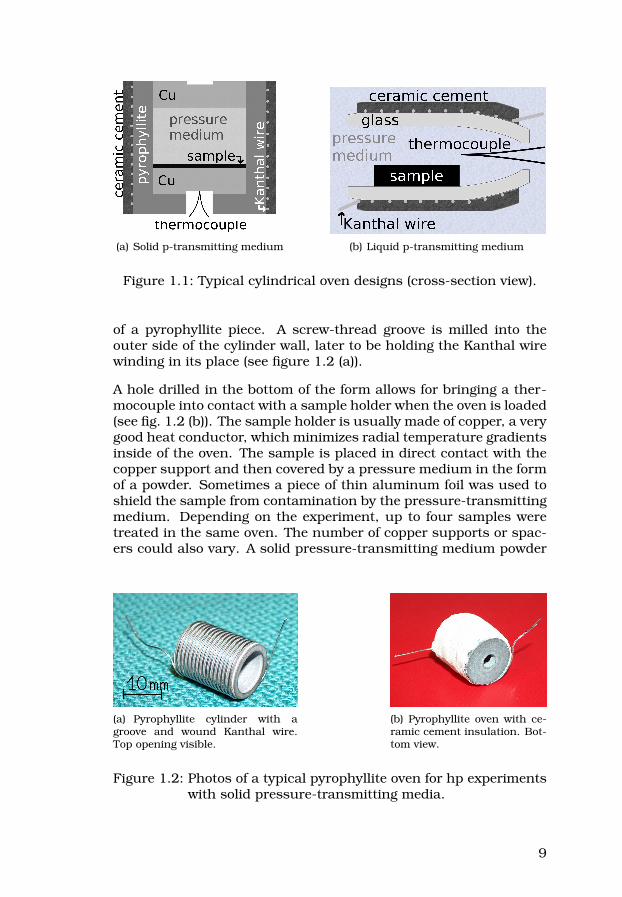
(a) Solid p-transmitting medium (b) Liquid p-transmitting medium
Figure 1.1: Typical cylindrical oven designs (cross-section view).
of a pyrophyllite piece. A screw-thread groove is milled into theouter side of the cylinder wall, later to be holding the Kanthal wirewinding in its place (see figure 1.2 (a)).
A hole drilled in the bottom of the form allows for bringing a ther-mocouple into contact with a sample holder when the oven is loaded(see fig. 1.2 (b)). The sample holder is usually made of copper, a verygood heat conductor, which minimizes radial temperature gradientsinside of the oven. The sample is placed in direct contact with thecopper support and then covered by a pressure medium in the formof a powder. Sometimes a piece of thin aluminum foil was used toshield the sample from contamination by the pressure-transmittingmedium. Depending on the experiment, up to four samples weretreated in the same oven. The number of copper supports or spac-ers could also vary. A solid pressure-transmitting medium powder
(a) Pyrophyllite cylinder with agroove and wound Kanthal wire.Top opening visible.
(b) Pyrophyllite oven with ce-ramic cement insulation. Bot-tom view.
Figure 1.2: Photos of a typical pyrophyllite oven for hp experimentswith solid pressure-transmitting media.
9

is compressed during the experiment into a solid and does not re-turn to its initial form after pressure release. The oven also under-goes a plastic transformation and has to be destroyed in order torecover the samples.
For hp-hT experiments with liquid pressure-transmitting media theoven is prepared out of a Pyrex or soda glass tube, typically about3-6 mm in inner diameter. An about 20 mm long piece of a glasstube is cut and then formed using a high flame-temperature burnerto round all the edges and nearly seal one of the ends (as shown infig. 1.1 (b)). It disturbs the circulation of the medium into and outof the oven during the experiment and thus minimizes the chancesof washing out the sample(s). It is important, however, to leaveopenings on both ends, because otherwise a pressure differencebetween the inside and the outside of the oven could easily arise,crushing it. Sample(s) are loosely dropped into the oven. If thesamples are very small it is preferable to shield them by wrappingthem in a perforated aluminium foil or inserting them into small,open ended glass capilaries. A thermocouple is placed inside of theoven through one of the openings. It is often possible to performseveral experiments using the same oven and pressure cell.
An oven as a whole is mounted inside a cylindrical Teflon pressurecell, and soldered to copper contact wires. These, together withthe thermocouple wires exit the cell through the bottom gasket andchannels in the bottom piston (see figure 1.3).
In case of experiments employing a solid p-transmitting medium theoven is placed vertically, with the pyrophyllite cylinder axis paralellto the axis of pressure application. Such placement minimizes thechances of crushing the oven and allows for the best transmissionof pressure (usually also assisted by the Cu sample support act-ing as a mini-piston). The cell is filled with talc and glass beads,which provide additional heat insulation of the oven [8], and closedwith a Teflon lid. In case of a liquid pressure-transmitting medium,the applied pressure is hydrostatic, so that the oven orientation isnot influencing the chances of crushing it. Due to a risk of con-vection, which in the worst case might misplace the samples, theoven is mounted horizontally. Another convection-fighting methodis to fill the cell with pieces of temperature resistant, quartz fiberinsulation. Finally, the pressure-transmitting liquid is poured intothe cell and sealed by a Teflon lid. In all cases an indium-coatedring is sealing the top of the cell near the top piston edge. Contactwires are passing from the bottom of the pressure cell, through aTeflon disc and a metal gasket. Below, they are immobilized be-tween two thin truncated cones made of pyrophyllite. Finally, thewires exit the cylinder by channels milled in the sides of the bottom
10

(a) the separate elements (b) as mounted inside of the high pressurecylinder
Figure 1.3: Schematic view of the high pressure setup, as mountedfor an experiment with a solid pressure-transmittingmedium.
piston. The whole piston-cylinder setup is placed in a hydraulicpress (see figure 1.4) where high pressure is applied uniaxially be-tween the pistons and transformed to a quasi-hydrostatic pressureby the pressure-transmitting medium. The pressure is estimatedfrom the load based on a calibration curve determined in a sepa-rate experiment. The scaling of the load was done using a Manganinpressure gauge calibrated against the Hg melting line.
The temperature of a sample can be varied by regulating the currentthrough the heater wire. Heater geometries might vary, and theywill be described in connection to specific experiments in Part II.The experimental setup is usually also fitted with an external elec-tronic temperature regulator for keeping the temperature at stablevalues. Depending on the desired target temperature the necessarypower input is usually between 50 and 200 W.
The samples are typically annealed under high-pressure – high-
11

Figure 1.4: The red press (ASEA Quintus no.1).
temperature conditions for 1-4 hours in order to assure enoughtime for the whole sample to react. At very high temperatures,however, reactions are rapid and it is safe to assume that mostof the material has reacted within the first few minutes of the treat-ment. This is rather convenient, especially in case of experimentsrequiring sample treatment at extreme conditions and/or where theexperimental setup does not allow for long annealing times.
1.2 Raman spectroscopy
1.2.1 Basic principles
Raman spectroscopy is studying the inelastic scattering of laserlight from a sample. Photons can interact with a sample by excitingor absorbing optical phonons. The secondary photons emitted fromthe sample after such an interaction exhibit frequency shifts corre-sponding to the allowed phonon modes in the sampled material. Inthis way the analysis of scattered light based on energy conserva-tion provides information about the specimen’s symmetry and itsalterations. It is possible to study molecular vibrations and to sam-ple optical modes of a crystal lattice. A more detailed description ofthe method can be found e.g. in [4].
Depending on the type of the interaction with the sample materialRaman scattering can be divided into two categories, schematicallyshown in figure 1.5.
12

Figure 1.5: Raman scattering in the Stokes and anti-Stokes geome-tries.
The process where the incident photon’s energy is partly used tocreate a phonon and the resulting photon has a lowered frequencyis called a Stokes process
~ωf = ~ωi − ~ωS(k) (1.1)
where ωi and ωf are, respectively, the frequencies of the incidentand the final photon, and ωS(k) is an allowed phonon frequency.
If, however, the exiting phonon has a higher frequency than theinitial one, as a consequence of absorbing energy from a phonon,the process is called anti-Stokes process
~ωf = ~ωi + ~ωS(k) (1.2)
Raman spectra for most materials have qualitatively identical Stokesand anti-Stokes components, while the anti-Stokes intensities aremuch lower due to a lower probability of such scattering events.
Not every molecular vibration, however, can be studied with Ra-man spectroscopy. In order for Raman scattering to take placethe molecule has to be affected by a vibrational mode in such away, that its polarizability is changed1. In this way the outgoingphotons reflect the modification of the molecule’s optical response(while the interaction is taking place) by a vibration. A Raman ac-tive vibrational mode is mechanically deforming a molecule, varyingthe distances between the atoms, and in this way constantly mod-ulating the polarizability with the frequency of the given molecule’svibration.
1And the vibrations which cause a change in a dipole moment of the molecule are IRactive. In general a vibrational mode can be Raman or IR active, active for bothRaman and IR spectroscopy or silent. In some cases more constraints apply.Vibrational modes typical for specific materials will be discussed later.
13
Conventionally, the Raman shift is expressed in inverse wavelength,wavenumber units [cm-1]. On an absolute scale the wavenumber isrelated to the wavelength as
k =1λ
. (1.3)
However, the Raman spectra are recorded as a shift in k with re-spect to an original excitation wavenumber, calculated as in theequation above.
1.2.2 The setup
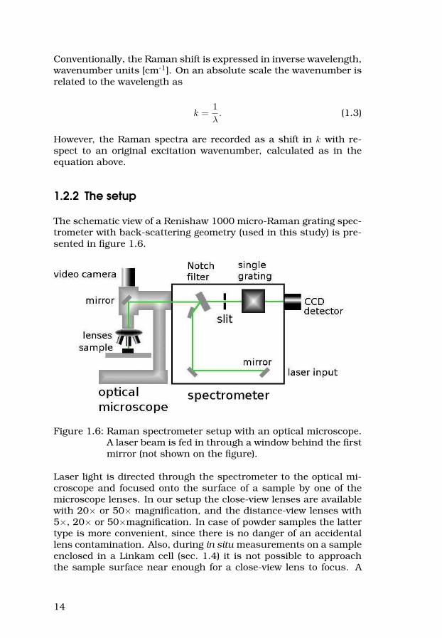
The schematic view of a Renishaw 1000 micro-Raman grating spec-trometer with back-scattering geometry (used in this study) is pre-sented in figure 1.6.
Figure 1.6: Raman spectrometer setup with an optical microscope.A laser beam is fed in through a window behind the firstmirror (not shown on the figure).
Laser light is directed through the spectrometer to the optical mi-croscope and focused onto the surface of a sample by one of themicroscope lenses. In our setup the close-view lenses are availablewith 20× or 50× magnification, and the distance-view lenses with5×, 20× or 50×magnification. In case of powder samples the lattertype is more convenient, since there is no danger of an accidentallens contamination. Also, during in situ measurements on a sampleenclosed in a Linkam cell (sec. 1.4) it is not possible to approachthe sample surface near enough for a close-view lens to focus. A
14

larger distance between the sample and the lens does not allow,however, for very efficient scattered light focusing and typically thesignal intensity is lower as compared to using the correspondingclose-view lens. The choice of lens’ magnification depends on thetype of information which is to be gained: higher magnification fo-cuses the laser spot on a smaller area. In this way spectra can begathered very locally, on a selected fragment of a sample. If, how-ever, the signal is to be averaged over a bigger area of the sample, orwhen high laser intensity can harm the sample, a lens with lowermagnification should be used.
The position of the laser spot on a sample can be controlled bya video camera and a micrometer translation stage on which thesample is resting. The back-scattered light after interfering withthe sample is directed back into the spectrometer, where a notchfilter cuts away a window in the spectrum, including the originalwavelength. This is necessary in order to avoid the saturation ofthe CCD detector by high intensity elastically scattered (Rayleigh)light. The Raman-scattered light is then passing through a slit ontoa single grating which separates the spectrum which is then regis-tered by a CCD detector. In this way the intensity can be registeredat each wavenumber separately, scanning over the desired range ofthe photon frequency spectrum.
Our spectrometer is equipped with three lasers. We have addition-ally tried to study some samples with a Renishaw inVia spectrom-eter with a UV laser, at the lab of prof. Bingbing Liu, Changchun,China. All four lasers are listed in table 1.1.
Table 1.1: Lasers used in the Raman spectroscopy studies.Laser Color Wavelength WavenumberDiode deep red - IR 780 nm 12 821 cm-1
Helium-Neon(He-Ne)
red 632.5 nm 15 810 cm-1
Argon ion (Ar+ ion) green 514.5 nm 19 436 cm-1
Helium-Cadmium(He-Cd)
ultraviolet 325 nm 30 769 cm-1
1.3 Photoluminescence
The luminescence spectrum, i.e. the analysis of light emitted bythe sample, provides an insight into the electronic structure of thematerial. It can be excited by illumination of the sample with ei-ther monochromatic or continuous-wavelength light, in which case
15

we talk about photoluminescence (PL). There is a lot to learn fromPL, since the emission of light occurs at frequencies correspond-ing to the allowed electronic transitions in the material. In thesimplest case, if a sample is illuminated by photons with ener-gies resonant with the energy of an existing electronic transition,the light will be absorbed and re-emitted at the same frequency, al-most immediately afterwards. Often, however, the irradiation is atenergies higher than resonant and in that case more complicatedprocesses may take place. An excitation (which must follow theselection rules) may be followed a by non-radiative dissipation ofenergy and a subsequent PL transition between two states of thesame spin multiplicity (typically singlet to singlet), which is calledfluorescence. If, before the radiative decay occurs, the excitation istransfered between two excited states of different spin multiplicity(singlet to triplet), the transition back to the ground state is spin-forbidden, and thus unlikely. The PL, in such a case called phos-phorescence, occurs eventually, but often much delayed.
Let us now consider a molecule, for example a C60, which canvibrate. Molecular vibrations affect the position of the positivelycharged atom nuclei (ions). Negatively charged electron clouds areinfluenced by that movement, but the huge difference in the iner-tia between heavy nuclei and light electrons makes the reactiontimescales very different. The interaction between electrons and thevibrating nuclei are visible “from outside” as a modification of themolecular electronic state structure, and results in a build-up of aladder of so-called vibronic (vibrational + electronic) energy stateson top of each initial electronic state. When a molecule absorbs anon-resonant photon, it is excited to a vibronic state, i.e. besidesthe electronic transition a vibration is excited. At the timescale of atypical electronic process, however, heavy ions at each moment ap-pear to be static, just placed out of equilibrium positions. The elec-trons adapt almost instantenuously to each excitation (changingthe orbital shapes and thus the symmetry), while re-arrangementof ions takes more time. At this point the Franck-Condon principleapplies: that vibronic transition (for now: the illumination-causedexcitation from the ground state) is favoured which requires min-imal adjustments to the nuclei positions (or, in other words, thewavefunctions of the two states involved are overlapping), and thatdoes not always apply to a purely electronic transition. The Franck-Condon principle in action is illustrated in figure 1.7.
The subsequent non-radiative dissipation of energy takes place, byrelaxation of the positions of the nuclei. It brings the molecule tothe bottom of the excited vibronic ladder, that is, to the “bare” elec-tronic excited state with corresponding equilibrium positions of thenuclei. When PL occurs, the Franck-Condon principle is employed
16

Figure 1.7: Franck-Condon principle for absorbtion and PL. Figureadapted from Wikipedia.org.
again, and the radiative, PL transition ends up somewhere on avibronic ladder of the ground state.
The Franck-Condon principle is thus very useful in the interpre-tation of PL data. The peak positions correspond to energy dif-ferences beween the excited electronic state and vibronic groundstates, and the intensity of each peak carries information aboutstate symmetries. Still, PL spectra of C60 are rather complex anddifficult to decipher, with loads of symmetry considerations to betaken into account and some processes, like Jahn-Teller distor-tions, still complicating the problem. On top of that, very low tem-peratures are needed to eliminate the line broadening and resolveindividual peaks in the spectra.
From a practical point of view, a spectrometer is needed for record-ing of the photoluminescence data, and in our work a Raman spec-trometer is employed for that. On one hand, it is convenient be-cause of the laser feed which is used for sample illumination andthe Linkam cell for cooling. On the other hand, the detection range
17

is limited, and we have no means to measure absorption, so we arenot able to study the vibronic structure of excited states.
1.4 Low temperature luminescence andRaman spectra
In order to study luminescence of our samples (as well as Ramanspectra) over a range of temperatures between 77 K and room tem-perature a sample was placed inside of a Linkam cryostatic cell (fora schematic sketch see fig. 1.8). The Linkam cell allows for opti-cal studies in a controlled environment (e.g. inert atmosphere andaccurate temperature control). The stage is made of silver (goodthermal conduction), to provide fast and reliable adjustments tothe temperature of a sample, both on heating and cooling. A sam-ple should be in a good thermal contact with the stage, thereforeonly very little material is used in such studies. For example, spec-tra of isolated crystallites (lying directly on the Ag surface) can berecorded. The small sample mass is also an advantage while ad-justing the temperature, because it allows for fast and reliable tem-perature changes.
Samples are loaded into the Linkam cell inside a glovebox filledwith Ar gas to minimize the amount of water vapour trapped in andaround the sample. This is done in order to avoid water conden-sation and freezing on the sample surface while cooling. It alsoprovides an inert atmosphere for the samples. Small amounts ofwater could still be observed (and believed to originate from a waterlayer adhered to the inner surfaces of the cell, even while insidethe glovebox2) but in most cases it was not disturbing the measure-ments. Cooling was provided using liquid nitrogen (LN2).
The temperature is regulated and maintained by an external elec-tronic controller, managing both pumping rate for the cooling me-dium and the heater output. It is possible to set a desired targettemperature, a rate of cooling and a time to keep the sample at thesetpoint temperature.
The luminescence spectra were excited using Ar+ and He-Ne lasersand recorded by the Raman spectrometer setup (see figure 1.6).The data recorded as a Raman shift on the Stokes side (a distancein wavenumbers from the original laser line) was translated intoabsolute wavenumber values as2It is in principle possible to eliminate the adhered water layer by heating the whole
cell, however this was not possible because of the plastic contacts which couldmelt at high temperature.
18
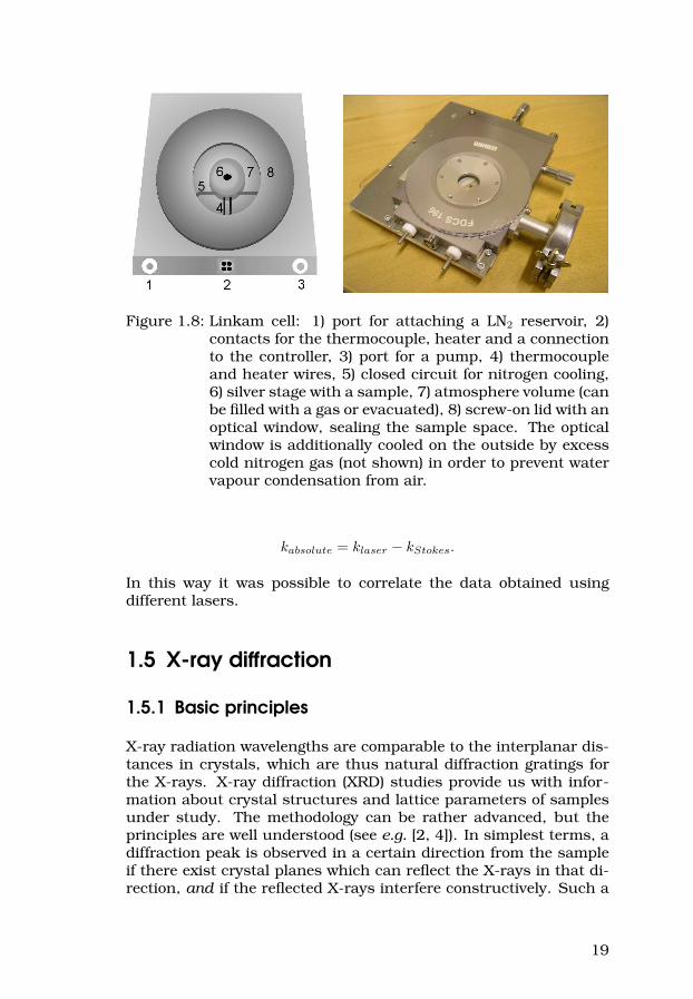
Figure 1.8: Linkam cell: 1) port for attaching a LN2 reservoir, 2)contacts for the thermocouple, heater and a connectionto the controller, 3) port for a pump, 4) thermocoupleand heater wires, 5) closed circuit for nitrogen cooling,6) silver stage with a sample, 7) atmosphere volume (canbe filled with a gas or evacuated), 8) screw-on lid with anoptical window, sealing the sample space. The opticalwindow is additionally cooled on the outside by excesscold nitrogen gas (not shown) in order to prevent watervapour condensation from air.
kabsolute = klaser − kStokes.
In this way it was possible to correlate the data obtained usingdifferent lasers.
1.5 X-ray diffraction
1.5.1 Basic principles
X-ray radiation wavelengths are comparable to the interplanar dis-tances in crystals, which are thus natural diffraction gratings forthe X-rays. X-ray diffraction (XRD) studies provide us with infor-mation about crystal structures and lattice parameters of samplesunder study. The methodology can be rather advanced, but theprinciples are well understood (see e.g. [2, 4]). In simplest terms, adiffraction peak is observed in a certain direction from the sampleif there exist crystal planes which can reflect the X-rays in that di-rection, and if the reflected X-rays interfere constructively. Such a
19
constructive interference for the radiation diffracted on a particularset of crystal planes occurs when the Bragg condition:
nλ = 2d sin θ
is satisfied (n is an integer known as order of reflection, λ is theradiation wavelength, and θ is the Bragg angle between the crystalplane and the incoming X-rays). A distance between crystal planesd is related to the Miller indices (hkl) of the crystal plane family andthe lattice constant(s). For example in the case of a cubic latticewith a lattice constant a we get:
d =a√
h2 + k2 + l2
Depending on the symmetries, the chemical composition and theratios between lattice parameter values for a certain material addi-tional constraints may apply and some peaks might be forbidden orcancelled.
Luckily, XRD theory is well developed and in all cases capable ofexplaining the experimental data. Practically, however, in case ofdiffraction patterns obtained on unknown samples one often hasto guess the lattice structure and estimate its parameters. Sucha guess has to be verified by comparison of the experimental datato the theoretically predicted peak positions and followed by thefine tuning of the parameters. There exists a number of computerprograms which can be used for that purpose.
1.5.2 The setup
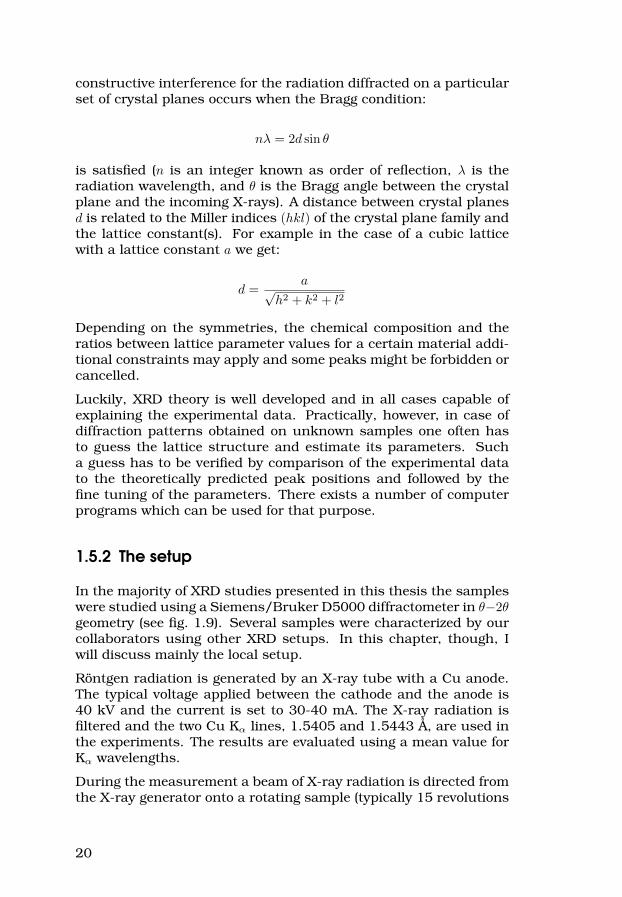
In the majority of XRD studies presented in this thesis the sampleswere studied using a Siemens/Bruker D5000 diffractometer in θ−2θgeometry (see fig. 1.9). Several samples were characterized by ourcollaborators using other XRD setups. In this chapter, though, Iwill discuss mainly the local setup.
Röntgen radiation is generated by an X-ray tube with a Cu anode.The typical voltage applied between the cathode and the anode is40 kV and the current is set to 30-40 mA. The X-ray radiation isfiltered and the two Cu Kα lines, 1.5405 and 1.5443 Å, are used inthe experiments. The results are evaluated using a mean value forKα wavelengths.
During the measurement a beam of X-ray radiation is directed fromthe X-ray generator onto a rotating sample (typically 15 revolutions
20
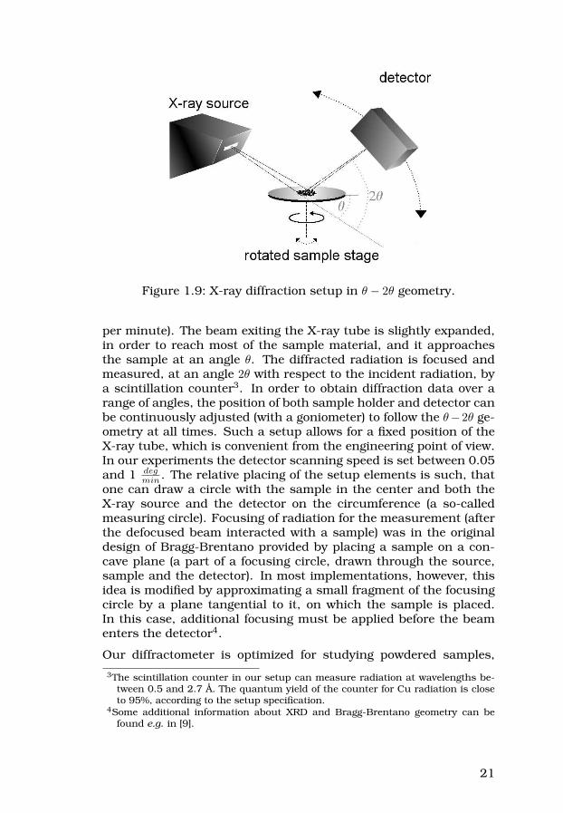
Figure 1.9: X-ray diffraction setup in θ − 2θ geometry.
per minute). The beam exiting the X-ray tube is slightly expanded,in order to reach most of the sample material, and it approachesthe sample at an angle θ. The diffracted radiation is focused andmeasured, at an angle 2θ with respect to the incident radiation, bya scintillation counter3. In order to obtain diffraction data over arange of angles, the position of both sample holder and detector canbe continuously adjusted (with a goniometer) to follow the θ−2θ ge-ometry at all times. Such a setup allows for a fixed position of theX-ray tube, which is convenient from the engineering point of view.In our experiments the detector scanning speed is set between 0.05and 1 deg
min . The relative placing of the setup elements is such, thatone can draw a circle with the sample in the center and both theX-ray source and the detector on the circumference (a so-calledmeasuring circle). Focusing of radiation for the measurement (afterthe defocused beam interacted with a sample) was in the originaldesign of Bragg-Brentano provided by placing a sample on a con-cave plane (a part of a focusing circle, drawn through the source,sample and the detector). In most implementations, however, thisidea is modified by approximating a small fragment of the focusingcircle by a plane tangential to it, on which the sample is placed.In this case, additional focusing must be applied before the beamenters the detector4.
Our diffractometer is optimized for studying powdered samples,
3The scintillation counter in our setup can measure radiation at wavelengths be-tween 0.5 and 2.7 Å. The quantum yield of the counter for Cu radiation is closeto 95%, according to the setup specification.
4Some additional information about XRD and Bragg-Brentano geometry can befound e.g. in [9].
21

placed on a substrate (here: Si or glass) and distributed into a cir-cle, about 1 cm in diameter (approximate width of the X-ray beam).The sample should be well dispersed, ideally with all the powderat the same, minimal distance from the position of the substratesurface, at which the angle calibration of the device is based. Thiscan be done by adding a drop of ethanol to the powder, and al-lowing the suspension to slowly dry out. A common practice is tomix the sample with a reference (e.g. Si powder) and calibrate thedata against the known peaks of the reference material. Here it wasnot done because small samples gave a weak signal and for even avery small amount of Si powder added the reference peaks wouldcompletely dominate the spectrum. Moreover, we did not want tocontaminate our samples.
The choice of a substrate material is an important issue in X-raydiffraction spectroscopy. The radiation is able to penetrate a thinsample and reach the substrate, which can affect the measurementresults. In an ideal case the substrate should be completely amor-phous, not to contribute at all to the scattered radiation. Glass iscontributing with a small broad background with no sharp peakswhich can be rather easily subtracted from the results. The otherpossibility is a highly crystalline substrate with sharp peaks atknown positions (preferably far from the positions of expected sam-ple peaks) which can be easily identified.
In case of samples which are sensitive to air and/or water, the ori-ginal design of the sample holder is not suitable. Sensitive sampleswere sealed inside of a 0.5-1.5 mm diameter special glass capillaryunder a controlled atmosphere and studied on a specially designedsample holder. It has a capillary-supporting groove, such that thetop of a sample is at the same height as it would be in case ofa standard sample holder. Unfortunately, such a capillary holdercannot be automatically rotated by the stage (because that wouldbring the sample out of focus at most positions), which means thatthe data is not optimally averaged. The only way around this is topause the measurements every now and then and manually rotatethe capillary around its axis. Another option is to mount a capillaryso that it vertically crosses the middle of the rotating ”standard”sample holder, but then even a smaller amount of the sample islocated within the reach of X-rays.
The diffraction geometry used in our studies was dictated by thetype of X-ray diffractometer available in place. The θ − 2θ Bragg-Brentano geometry is not the most optimal in some cases, espe-cially with small sample amounts, that may result in a relativelylow signal to noise ratio. Due to the construction of the XRD setupit is also not possible to record reflections at 2θ below 8.
22

1.6 Scanning probe microscopy
1.6.1 General principles
Scanning probe microscopy (SPM) is one of the youngest surfacecharacterization methods, first demonstrated in 1981 by Gerd Bin-nig and Heinrich Rohrer, who were awarded a Nobel Prize in Physicsin 1986. The first of the SPM family of methods, scanning tun-nelling microscope (STM), monitors the tunnelling current betweena conducting sample and a sharp metallic tip. Numerous otherimaging techniques were proposed, joined almost only by the mainprinciple. A nanosized tip (probe) is interacting at close range witha very small sample surface region. By moving the tip around thesurface and keeping a chosen feedback parameter fixed, an imageof a bigger area is obtained, as a combination of the measurementresults at each separate point. Sub-nanometer movement precisionin all three dimentions is required, which can be achieved by piezo-electric material actuators built into a scanner. STM is capable ofsub-atomic resolution imaging due to the exponential dependenceof the tunnelling current amplitude on the tip-sample distance.Practically, most of the tunnelling occurs between the lowest lyingatom in the tip and the topmost atom in the sample, which providesenormous spatial resolution. The disadvantage of this methods is,however, the reqirement that the samples are conductive enough,which is not fulfilled in case of some carbon nanomaterials (e.g.fullerenes). Also, STM provides information about sample conduc-tivity rather than topography, which additionally complicates thecharacterization of mixed samples (with high vs. low conductivity).
Another SPM technique, more relevant for this thesis, is atomicforce microscopy (AFM). In this method a sharp tip (typically etchedSi) mounted on an elastic cantilever is scanned over a sample tomeasure the sample topography. As the method’s name alreadyreveals, the measurement is focused on the forces between the tipand the sample, which are recorded by monitoring the behaviourof the cantilever. Actually, the exact assignment of all the forcesinvolved5 between the tip and a sample may be difficult, since thecantilever is only sensing the collective effect of the total tip-sampleforce. The AFM imaging techniques can be divided into two maincategories, depending on how the cantilever is to be affected bythe tip-sample interaction, but the setup hardware arrangementfor both methods is basically the same (see figure 1.10).
The first AFM method is called Contact Mode scanning. The AFM tip
5Depending on the particular sample and tip, there may be several forces coexist-ing: van der Waals, electrostatic, chemical, capillary, etc.
23

Figure 1.10: A sketch of an AFM setup.
is brought into continuous contact with the sample surface and thefeedback loop is trying to maintain a constant force value betweenthe tip and sample. In Contact Mode the tip operates in a repul-sive regime of the tip-sample force, which is balanced by the elasticforce of the cantilever pushing the tip downwards. In a typical AFMsystem, a laser beam is deflected from the back of the tip-holdingcantilever and recorded by a position-sensitive, two-zone photode-tector. A constant tip-sample force means a constant value of thecantilever deflection, which corresponds, in turn, to a stable posi-tion of the reflected laser spot on the detector. When the spot movesaway from the middle of the detector, the tip-sample distance has tobe adjusted. This is done by a real-time feedback of the detector’serror signal to the piezoelectric scanner.
In the second, “dynamic” method, the cantilever is oscillated at aknown frequency (close to its resonance) and the interaction of thetip with the sample is modulating the cantilever oscillation. Thedetector’s error signal (RMS) is in this case steering the feedbackresponses. The dynamic method, depending on the details of itspractical realization is called Non-Contact, Intermediate-Contact orTapping Mode. In both static and dynamic cases, the topographyimage is calculated based on the feedback response, and it is simplya surface tracked by the piezoelectric scanner while keeping thefeedback parameter constant.
Obviously, each AFM method has its pros and cons. Some of the
24

differences are sumarized in table 1.2.
Table 1.2: Contact vs. Tapping AFMContact Mode Tapping Mode
Typical
cantilevers
Low spring constant. Long
(450µm) single-beam, or
triangular (100 or 200µm).
High spring constants.
Rather short, 100-225µm,
single-beam.
Typical tips
(name)
etched Si (ESP probes), SiN
(SP-20), typically less than
10 nm tip diameter.
etched Si (TESP, RTESP,
LTESP), typically less than
10 nm tip diameter.
Feedback
parameters
Cantilever deflection. Cantilever oscillation
amplitude, phase or
frequency.
Practical
resolution limits
Tip diameter, which can
deteriorate during scan.
Cantilever spring constant
value.
Quality factor of the
cantilever resonance.
Secondarily, tip diameter.
Sensitivity to
capillary forces?
Not affected, scanning in a
constant contact with the
sample’s surface, submerged
in the adhered water layer (if
any).
Affected, the tip is constantly
put in and out of the water
layer (if any), and has to fight
the capillary forces.
Effects on the
sample
Shear forces between tip and
sample are present. Soft
samples may get scratched.
Very small forces needed for
scanning, no shear forces
between tip and sample.
Suitable for soft materials.
Atomic or
molecular
resolution?
False atomic resolution.
Moiré pattern on a periodic
surface might reflect the
atomic/molecular
arrangement, but no defects
can be imaged. In that way
capable of resolving C60
molecules while imaging in
air.
Capable of true atomic
resolution, but only while
operating in non-contact
mode and under ultra-high
vacuum. Lower quality factor
while operating in air, worse
sensitivity.
1.6.2 The setup
In our setup (MultiMode AFM from Veeco Metrology), while scan-ning, the AFM feedback is trying to maintain a constant cantileverdeflection (Contact Mode) or, alternatively, a fixed cantilever oscil-lation amplitude (Tapping Mode). In each case, the error signal (i.e.the difference between the setpoint and the just-recorded value)
25

is measured in each step, multiplied by proportional and integralfeedback parameters, and in real time fed as a modulation to thepiezoelectic scanner voltage in order to correct the tip-sample rela-tive position and, in turn, correct the value of the feedback param-eter.
Our AFM is optimized for operation in air. Depending on the choiceof the piezoelectric scanner to be used the maximum scanning areacan be up to 125 µm × 125 µm, but with the most universal andstill very precise “E” scanner it is limited to just over 13 µm × 13 µmand about 5 µm in the z-direction. The choice of image resolutionis always a trade-off between the high accuracy of data and data-acquisition time, which should be as short as posible. With typicalscanning rates of the order of 1 Hz (≈1 line per second, and depend-ing on the scan size from 0.1 to 30 Hz) and image resolution of 256lines × 256 points or 512 lines × 512 points, a full image is obtainedin a few to a few tens of minutes. Too fast data acquisition posesa risk of not ideal surface tracking and major feedback overshots,while too slow masurements are affected by drift of the piezoelec-tric scanner. When the AFM is placed on a vibration-damping stageand covered by a sound-proof hood it is possible to obtain images at“molecular resolution” (averaged Moiré pattern, no defects visible)on flat, crystalline surfaces, e.g. on a C60 solid.
26

2 C60 fullerene
2.1 The molecule
The C60 molecule was discovered in 1985 by Robert F. Curl Jr.,Harold W. Kroto and Richard E. Smalley with co-workers [10]. Sur-prisingly, the discovery was actually a side effect of a radioastro-nomical study. Professor Sir Harold Kroto gives a brief account ofthis story in his web-based CV [11]:
“(1975-1980) Laboratory and radioastronomy studies on long linearcarbon chain molecules (the cyanopolyynes) led to the surprising dis-covery (by radioastronomy) that they existed in interstellar spaceand also in stars. Since these first observations the carbon chainshave become a major area of modern research by molecular spectro-scopists and astronomers interested in the chemistry of space.
(1985-1990) The revelation (1975-1980) that long chain molecules ex-isted in space could not be explained by the then accepted ideas oninterstellar chemistry and it was during attempts to rationalise theirabundance that C60 Buckminsterfullerene was discovered. Labora-tory experiments at Rice University, which simulated the chemical re-actions in the atmospheres of red giant carbon stars, serendipitouslyrevealed the fact that the C60 molecule could self-assemble. This abi-lity to self-assemble has completely changed our perspective on thenanoscale behaviour of graphite in particular and sheet materials ingeneral. The molecule was subsequently isolated independently atSussex and structurally characterised.”1
C60 is a closed-cage molecule consisting of sixty carbon atoms. Themolecular structure can be described as a truncated icosahedron,with 12 pentagonal and 20 hexagonal faces (see figure 2.1). Theconstruction of a C60 cage is similar to one of the architecturalprojects by Richard Buckminster Fuller (A geodesic dome, The Mon-treal Biosphére, formerly the American Pavilion of Expo 67)2. The1R.F. Curl, R.E. Smalley and their group performed the laser ablation experiments
at Rice University, and Harry Kroto was working mainly with spectroscopy atSussex.
2It also inspired a design of the most widespread soccer ball - a so called Buck-minster Ball, officially approved by FIFA for 1970 World Cup in Mexico. Theresemblance of a C60 molecule to this well known black and white football iseven more evident than the comparison to the original geodesic dome.
27

Figure 2.1: A C60 molecule.
resemblance was acknowledged when naming the newly discoveredmolecule, and led to common use of names such as a buckmin-sterfullerene, a buckyball or simply a C60 fullerene (the latter beingmost popular).
C60 molecules were for the first time synthesized using a powerfullaser to ablate graphite into He carrier gas (a method proposed byR.E. Smalley, and capable of vaporizing and producing nanosizedclusters of virtually any material). The carbon vapour was cooled,partially starting to condense and expanded into a vacuum in a su-personic molecular beam. The produced carbon clusters were ion-ized and studied by mass spectrometry. A peak at sixty-atom clus-ter size – much stronger than peaks for neighboring sized clusters– provided evidence that there exists a stable structure consistingof exactly sixty carbon atoms.
It was postulated that the newly discovered molecule was a closedcage structure, hollow inside. An additional strong argument forsuch a structure was the fact that all the carbon clusters detectedabove 40 carbons in size were always composed of an even numberof atoms. Euler’s theorem applies to these kind of structures:
A network of trivalent nodes comprising P pentagons andH hexagons contains n = 6H+5P
3 nodes, b = 6H+5P2 bonds
and a = H + P areas.
In order to obtain a closed surface one has to comply with the re-quirement that P = 12, with no further constraint for the num-ber of hexagons (which follows from Euler’s relation for polyhedra:n− b + a = 2). In addition, having two pentagons sharing an edge isenergetically unfavorable (isolated pentagon rule [12, 13]), becauseit leads to locally higher curvature and thus more stressed bonding.Due to the fact that the C60 cage (icosahedral isomer) is the small-est geometrical structure in which no two of the twelve pentagons
28

are sharing edges, it is the smallest stable fullerene construction.The next one is the C70 molecule; however in the case of higherfullerenes there are usually several such isomers for each clustersize and the symmetry of the molecules is lower.
Carbon bonds on a C60 molecule belonging to pentagons are sin-gle bonds, and the bonds shared between two hexagons are doublebonds. Therefore all four valence electrons of each C atom are in-volved in the creation of covalent bonding. A fullerene might beregarded as a spherically shaped graphene sheet, where the carbonbonds are very similar to the bonds in planar graphite (sp2 hy-bridization). However, the curvature of the fullerene surface leadsto a distortion of the bonding character in the direction of sp3
type hybridization (as in diamond), the more so the smaller thefullerene’s radius is.
All the carbon atoms on a C60 molecule are indistinguishable fromeach another on a geometrical basis (i.e. every atom has one dou-ble and two single bonds and each atom’s position on the moleculeis geometrically identical). The molecule is highly symmetric, de-scribed by the icosahedral point symmetry group (Ih) with a total of120 symmetry operations3, including:
F identity operation E,
F 12 of each fivefold rotations C5 and C25 (around axes crossing
the centers of pentagons)4,
F 20 threefold rotations C3 (axes in centers of hexagons),
F 15 twofold rotations C2 (around the axes connecting the cen-ters of double bonds on the two opposite poles of a fullerene),
F inversion i,
F 12 improper rotations S310 (including iC5 = S−1
10 )5,
F 12 improper rotations S10 (with S10 = iC−15 ),
F 20 improper rotations S3 ,
F 15 vertical6 mirror planes σv .
The icosahedral symmetry point group Ih has ten irreducible repre-sentations7:
Ag , Au , F1g , F1u , F2g , F2u , Gg , Gu , Hg and Hu .
3To get an overview of symmetry point groups, symmetry operations, etc., see e.g.[4, 14].
4Ckn denotes a clockwise rotation around a given axis by an angle 2πk
n.
5An improper rotation Skn is a regular rotation Ck
n followed by a reflection in theplane perpendicular to the axis of rotation.
6passing through the origin and including a highest symmetry axis7Some authors use a different notation: T1 and T2 instead of F1 and F2.
29

Some physical properties of the C60 molecule8 are presented in ta-ble 2.1.
Table 2.1: Physical properties of C60.
Property ValueAverage C-C distance 1.44 ÅC-C bond length on a pentagon (singlebond)
1.46 Å
C=C bond length on a hexagon (doublebond)
1.40 Å
C60 mean ball diameter 7.10 ÅC60 ball outer diameter 10.34 ÅMoment of inertia I 1.0× 10−43 kg
m2
Volume per C60 1.87× 10⁻²² 1cm3
Number of distinct C sites 1Number of distinct C-C bonds 2Binding energy per atom 7.40 eV
Heat of formation (per g C atom) 10.16 kcal
Electron affinity 2.65± 0.05 eV
Cohesive energy per C atom 1.4 eVatom
Spin-orbit splitting of C (2p) 0.00022 eV
First ionization potential 7.58 eV
Second ionization potential 11.5 eV
Optical absorption edge 1.65 eV
C60 can be synthesized by various methods, usually involving cre-ation of a hot carbon plasma. A carbon-rich vapour is obtainedby e.g. resistive heating of carbon rods in vacuum, laser ablationof graphite, arc discharge or by other methods. The yield dependson the method used and the resulting material needs to be fur-ther purified to extract C60 from the rest of the reaction products.The details of various synthesis and purification processes weredescribed elsewhere (e.g. [3]) and will not be presented here. Itis worth mentioning, however, that the experimental research onfullerenes was greatly broadened after the new method of produc-tion was proposed by Krätschmer et al. in 1990 [15], and it becamepossible to produce C60 in considerable quantities.
8The values are collected from many articles, and here they are presented as aquote from [3], where all the original references are listed in detail.
30

2.2 Vibrational modes
Vibrational modes of a C60 molecule are directly related to its struc-ture and symmetry. There are altogether 180 degrees of freedom(three per atom). Three of those are translations, another 3 are ro-tations, and the leftover 174 are the vibrational degrees of freedom.Due to the high symmetry of the molecule many of those are degen-erate in frequency. Theoretically there should only be 46 distinctfrequencies. These vibrations with their corresponding symmetriesare:
Γ = 2Ag + 3F1g + 4F2g + 6Gg + 8Hg + Au + 4F1u + 5F2u + 6Gu + 7Hu
Out of these, there are 10 Raman active even parity modes (2Ag +8Hg) and four F1u odd parity infrared active modes. For this thesisespecially three vibrational modes have significant meaning: Hg(1),Ag(1) and Ag(2), which are shown in fig. 2.2.
(a) Hg(1) "rugby ball"mode
(b) Ag(1) " radial breath-ing" mode
(c) Ag(2) "pentagonalpinch" mode
Figure 2.2: Selected vibrations of C60.
The Hg(1) mode deforms the molecule into a rugby ball shape (as ifpulling on the opposing poles of the molecule and simultaneouslyshrinking the equatorial circumference, see fig. 2.2 (a)) and backto the spherical form. It is a low frequency mode, affecting themolecule as a whole, where the deformation is very directional (anaxis can be drawn along which the molecule is stretched). It isin principle possible to shift the five-fold degeneracy of this mode,however in pristine C60 this does not occur. In case of pristineC60·C8H8 (which will be described in chapter 5) the mode is repre-sented by two peaks, which we interpret as the distinct frequencieswhen the C60 molecule is vibrating in the direction of neighbor-ing cubanes (see chapter 4) or between them, towards nearest C60
neighbors.
31

The Ag(1) mode is a “radial breathing” mode, expanding and con-tracting the whole molecule (fig. 2.2 (b)). The Ag(2) mode, a so-called“pentagonal pinch” mode (fig. 2.2 (c)), is a tangential mode in whichall the pentagons on the molecule are “breathing”. This vibrationis caused by contracting and extending all the double bonds onthe C60, and therefore the mode is very sensitive to any covalentbonding of C60 to its environment, which affects the double bondson the molecule. More about the behaviour of the Ag(2) mode onpolymerization can be found in sections 2.4.1 and 2.4.2.
Both Ag(1) and Ag(2) modes, being non-degenerate, can be used as“sensors” of mixed material phases. It is not possible to split an Ag
mode, so whenever additional peaks appear in a Raman spectrum itmeans that multiple phases are present, each resulting in a slightlydifferent Ag mode frequency.
2.3 Crystal structure
Under ambient conditions C60 molecules arrange into a face-centeredcubic (f.c.c.) crystal lattice (see figure 2.3).
Figure 2.3: Face-centered cubic arrangement of C60 molecules. Un-der ambient conditions the molecules are freely rotatingin their positions.
The most stable crystal faces are the close-packed (111) and (100)planes. It is possible to grow C60 crystals e.g. from a solution orby vacuum sublimation of C60 powder inside a two-zone oven. Itis possible to control the crystal growth by adjusting the growthconditions or by using a carefully selected shape controller. It is
32

possible to obtain relatively big crystals (up to a few mm range),and on the other hand also to grow C60 nanorods (see Paper I) orC60 nanosheets.
At normal conditions C60 molecules are freely rotating inside a crys-tal, but below T = 261 K they become fixed orientation-wise, due tothe loss of two out of the three rotational degrees of freedom. Themolecules can only rotate about one of four [111] directions and theadjacent molecules have to orient in a specific manner, well corre-lated with their neighbors. In this way not all the positions in thelattice are equivalent. Therefore, at that temperature C60 crystalsundergo a phase transition to a simple cubic (s.c.) lattice. Thistransition occurs also at higher temperatures, if a crystal is subjectto high pressure (see the phase diagram in figure 2.4). At around90 K a second structural transition, to a glassy crystal, was ob-served. That transition, however, is not going to be discussed here.
Figure 2.4: Pressure-temperature phase diagram for C60. Reprinted(adapted) from Carbon, Vol. 36, V.D. Blank et al., “High pres-sure polymerized phases of C60”, p. 319-343, Copyright (1998),with permission from Elsevier.
Some properties of crystalline C60 are summarized9 in table 2.3.
9The values are collected from many articles, and here presented as a quote from[3] (unless referred otherwise), where the original references are listed in detail.
33

Table 2.3: Physical properties of crystalline C60 .
Property Valuef.c.c. lattice constant 14.17 ÅC60 - C60 distance 10.02 ÅC60 - C60 cohesive energy 1.6 eV
Tetrahedral interstitial siteradius 1.12 Å
Octahedral interstitial site radius 2.07 ÅMass density 1.72 g
cm3
Molecular density 1.44× 10²¹ 1cm3
Compressibility (− ddp lnV ) 6.9× 10⁻¹² cm2
dyn
Bulk modulus (f.c.c., 300 K) [16] 6.8 GPaBulk modulus (s.c.) [16] 8.7− 9.6 GPaYoung’s modulus10 15.9 GPaStructural transitiontemperature
261 K
Slope of the transition (dTdp )
[17, 18, 19]16 K
kbar , 162 KGPa
Vol. coeff. of thermal expansion 6.1× 10⁻⁵ 1K
Optical absorption edge 1.7 eVWork function 4.7± 0.1 eVVelocity of sound vt 2.1× 105 cm
s
Velocity of sound vl 3.6− 4.3× 10⁵ cms
Debye temperature 185 KThermal conductivity (300 K) 0.4 W
mK
Electrical conductivity (300 K) 1.7× 10⁻⁷ Scm
Phonon mean free path 50 ÅStatic dielectric constant 4.0− 4.5Sublimation temperature 434CHeat of sublimation 40.1 kcal
mol
Latent heat 1.65 eVC60
34

2.4 Experimental studies
C60 molecules became a subject of extensive experimental and theo-retical studies, by both physicists and chemists. C60 can be chem-ically functionalized, doped, filled with atoms other than carbon(forming so-called endohedral fullerenes), treated under various con-ditions, polymerized by hp-hT treatment or photopolymerized, addedas an ingredient in complex materials and then studied (e.g. TAED-C60 is ferromagnetic, with the highest transition temperature (T c =16.1 K) amongst organic magnets), put inside carbon nanotubes toform peapods, etc.
2.4.1 C60 polymerization
Due to their hollow sphere structure, C60 molecules are quite re-sistive to compression and relatively difficult to destroy by press-ing on them. Also, from many early studies it was evident thatthey can react and form covalent bonding (e.g. functionalization).An obvious question to ask would be if C60 can covalently bondto the neighboring C60 molecules. This question was answeredby several studies of C60 polymerization under different conditions[18, 19, 20]. Intermolecular covalent bonds between C60 moleculescan be formed provided that the molecules are brought togetherclose enough (high pressure) and have enough energy to create theintermolecular bonds (elevated temperature). The energy can alsobe provided by photons, causing photopolymerization (see e.g. [21,22, 23]). Photopolymerization, however is mostly driven by laser-excited higher electronic states of molecules which cause the elec-tron density to reach farther out. In this way the molecules canreact and form intermolecular bonds even when no pressure is ap-plied (i.e. molecules being farther apart).
Depending on the treatment conditions several phases can be iden-tified in the p-T diagram (see figure 2.4).
At relatively low pressure and temperature C60 molecules createdimers, with two intermolecular bonds. The mechanism of the in-termolecular bond creation is a so-called 2+2 cycloaddition; at highpressure the neighboring molecules are forced closer together and(due to their constant rotation, at some point in time) two near-est neighbors (in a (100) plane) can orient in such a way that theyface one another with parallel double bonds. Elevated tempera-ture causes that on each molecule one of the two bonds in a doublebond breaks and reconnects with the broken bond on the neighbor-ing molecule. In the new configuration the initially parallel, inter-molecular double bonds are replaced by a square of single bonds,
35

with pairs of inter- and intramolecular bonds forming the opposingedges. The creation of intermolecular bonds stops the molecularrotation and lowers the overall symmetry of the solid. Addition-ally, the reorganization of bonds affects the frequency of molecularvibrations, especially the Ag(2) pentagonal pinch mode (simultane-ous, consecutive stretching and contracting of all double bonds ona C60), which is visible as a downshift of the Ag(2) peak position inthe Raman spectrum. The magnitude of this shift is roughly pro-portional to the number of double bonds which were broken andreattached outwards, providing a convenient Raman fingerprint forall polymeric phases (sec. 2.4.2). Under hydrostatic pressure (oreven quasi-hydrostatic) dimers are created at random positions inthe lattice and in random orientation. That causes an increase inthe disorder, resulting in broadening of the XRD peaks. This kindof polymeric phase is created if the sample is heated after the finalpressure was applied.
Under the same conditions, if a longer annealing time is allowed,C60 polymerizes into linear chains, by connecting more moleculesto the ends of the dimers. These chains are of course still randomlyoriented along one of the three [110] directions in the f.c.c. latticeand are expected to be rather short. A more ordered 1D orthorhom-bic polymer (see figure 2.5 (a)), with longer linear chains of C60, canbe formed under more uniaxial pressure, if the samples are firstheated and the pressure is applied afterwards (e.g. by following apath 0 to 0.5 GPa11, room temperature to 300C, and finally 0.5 to1.5 GPa). The usual annealing time is 1–4 hours.
The choice of an experimental path through a p-T diagram has abig influence on the structure of a product material, even if thetarget annealing conditions should be identical. If the samples areheated under high pressure the polymerization starts as soon asa sufficiently high temperature is reached, and the almost instantformation of random, covalently bond dimers distorts the structureand introduces high disorder, frustrating further polymerization athigher temperatures. Heating at low pressures, on contrary, as-sures that molecules are not reacting with one another because ofthe large distances between them. Also, any polymeric bonds thatmight have been present in the starting material will be broken bythe increasing thermal energy of the molecules12. The polymer-ization starts in this case in a more controlled manner, when thepressure is sufficiently increased.
The latter method with the final temperature above about 700 K11A small load is applied in order to avoid leaks for the pressure cell.12This is also a way of “recycling” the polymerized samples to the pristine state. The
C60 polymerization can be thus reversed, if the samples are heated at very lowpressure.
36

and pressure above 2 GPa results in two-dimensional polymeriza-tion. At around 2 GPa a tetragonal polymer is formed (figure 2.5 (b)).Each C60 forms covalent double bonds with the four nearest neigh-bors in (100) plane. At even higher pressures (and temperatures) arhombohedral polymer is created (figure 2.5 (c)) when each fullereneconnects to all of its six neighbors in a close-packed (111) plane.
(a) Orthorhombic (1D) (b) Tetragonal (2D) (c) Rhombohedral (2D)
Figure 2.5: Polymeric phases of C60.
In all the polymeric phases the polymerization is irreversible in thesense that after quenching the temperature and pressure back toambient conditions the covalent intermolecular bonds are not bro-ken and the polymer structure is retained. It is possible, still,to depolymerize the samples by heating the samples at low pres-sures. Therefore the polymerization boundary is not strictly a phaseboundary, since crossing it from the side of polymeric phase doesnot trigger the transition back to a pristine state.
At temperatures about 900–1100 K (depending on the pressure)fullerene cages start falling apart and their fragments form a dense,partially graphitized, amorphous mixture of sp2 and sp3 bonded car-bon.
2.4.2 Raman spectra
Raman spectroscopy proved to be a very useful method to study andidentify the different C60 phases. As was already mentioned, eachpolymeric structure has a characteristic spectrum with especiallythe position of the Ag(2) mode being a fingerprint for each structure(see table 2.5).
37

Table 2.5: The position of the Ag(2) mode in the RT Raman spec-trum for various C60 phases [6].
PhaseNo. of intermolecular
(double) bonds permolecule
Ag(2) mode position
Pristine 0 1469 cm−1
Dimers 1 1464 cm−1
Orthorhombic 2 1459 cm−1
Tetragonal 4 1448 cm−1
Rhombohedral 6 1407 cm−1
The Raman spectra obtained with Ar+ (514.5 nm) excitation laserare presented in figure 2.6.
200 400 600 800 1000 1200 1400 1600
1427
1562
1572
973
947
708
485
29727
1
1464
C60 Dimers
416
432
589
710
954
977
1228 14
08
1566
1624
280
430
485 534
585
665 68
3
748
946
1038 11
08
1208
1447
1564
1572
257
277
344
454
491
715
770
774
967
1459
1196
1541
1577
273
430 49
6
706
774
1101
1251
157514
69Rhombohedral C60
Tetragonal C60
Orthorhombic C60
Pristine C60
Ram
an in
tens
ity [a
rb. u
nits
]
Wavenumbers [cm-1]
Figure 2.6: Raman spectra of C60 in pristine and polymeric phasesobtained using 514.5 nm excitation laser. Figure basedon data courtesy Dr. Thomas Wågberg.
Conveniently, the spectra of different material phases are very dis-tinct. Polymerization generally lifts the degeneracy of the modes, af-fects the position of some peaks and the relative intensities change.
38

2.4.3 X-ray diffraction
X-ray diffraction results on C60 were initially misinterpreted due tothe absence of the (200) reflection. That is why the crystal structureof C60 was initially believed to be a faulted hexagonal close-packedstructure. The (200) reflection is forbidden in a diamond structure(the structure factor for this reflection is equal to zero), which addi-tionally puzzled the early studies. The actual reason for the absenceof the (h00) family of peaks with even h is their angular position.The intensity of each reflection is scaled by a molecular form factor.In case of C60 it is proportional to the zero-order spherical Besselfunction [24]:
j0
(R
4π sin θ
λ
)=
sin(R 4π sin θ
λ
)R 4π sin θ
λ
, (2.1)
with θ being the Bragg angle, λ the wavelength of the X-rays andR the radius of C60’s charge distribution. This particular behaviourof the form factor is a consequence of the rotation of fullerenes atroom temperature, causing their charge density to average out to auniform spherical shell shape. The size of this shell determines theform factor zeroes which, in turn, cause cancelling of peaks at thesepositions. The molecular X-ray form factor for C60 (eq. 2.1) has anumber of zeroes, which happen to coincide with the positions ofeven h (h00) peaks for the f.c.c. structure with the lattice constantof pristine C60 (see inset in figure 2.7 (a)). The form factor scalesthe intensity of each reflection, and at its zeroes the intensity is notdetectable.
The XRD peaks for C60 are sharp, reflecting the high crystallinityof the material. As discussed in section 2.4.1 creation of poly-meric phases, and in particular dimers significantly increases thedegree of disorder, causing the broadening of XRD peaks (see fig-ure 2.7 (b)).
39
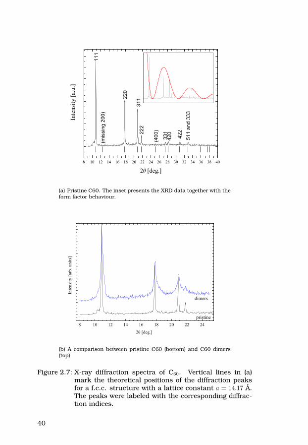
8 10 12 14 16 18 20 22 24 26 28 30 32 34 36 38 40
Inte
nsity
[a.u
.]
2 [deg.]
111
(mis
sing
200
)
220
33122
2
(400
)
311
420
422
511
and
333
(a) Pristine C60. The inset presents the XRD data together with theform factor behaviour.
8 10 12 14 16 18 20 22 24
Inte
nsity
[arb
. uni
ts]
2 [deg.]
pristine
dimers
(b) A comparison between pristine C60 (bottom) and C60 dimers(top)
Figure 2.7: X-ray diffraction spectra of C60. Vertical lines in (a)mark the theoretical positions of the diffraction peaksfor a f.c.c. structure with a lattice constant a = 14.17 Å.The peaks were labeled with the corresponding diffrac-tion indices.
40

3 Alkali metal intercalated C60
Alkali atoms (A) are easily intercalated into carbon nanostructuredmaterials. C60 is a very good electron acceptor and when providedwith electrons to steal it can accept up to six electrons per molecule.Allowing donors, like alkali metal atoms, into the fullerene latticevoids leads to a wide range of compounds with interesting proper-ties (for some of the first reports see e.g. [25, 26, 27, 28]). Numer-ous AxC60 compounds were produced and studied, with A = Li, Na,K, Rb, Cs or their combinations. Notably, the crystal structures(see figure 3.1) and conducting properties of AxC60 compounds arehighly dependent on the stoichiometry, i.e. the x value.
Figure 3.1: Structures of various alkali metal intercalated C60
phases. Reprinted from [26], Copyright (1992), with per-mission from Elsevier.
Intercalation of C60 with alkali metals is a relatively easy experimen-tal task which can be carried out in various ways. One has to keepin mind, however, that water and air are destructive for these mate-rials, and thus at all times care has to be taken to keep the samplesunder controlled atmosphere (e.g. Ar gas or vacuum). Also, produc-tion of samples with only one stoichiometric phase may require very
41
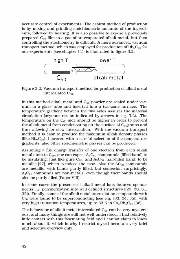
accurate control of experiments. The easiest method of productionis by mixing and grinding stoichiometric amounts of the ingredi-ents, followed by heating. It is also possible to expose a previouslyprepared C60 film to a gas of an evaporated alkali metal, but thencontrolling the stochiometry is difficult. A more advanced, vacuumtransport method, which was employed for production of Rb6C60 forour experiments (see chapter 11), is illustrated in figure 3.2.
Figure 3.2: Vacuum transport method for production of alkali metalintercalated C60.
In this method alkali metal and C60 powder are sealed under vac-uum in a glass tube and inserted into a two-zone furnace. Thetemperature gradient between the two sides assures the materialcirculation (asymmetric, as indicated by arrows in fig. 3.2). Thetemperature on the C60 side should be higher in order to preventthe alkali metal from condensating on the surface of C60grains andthus allowing for slow intercalation. With the vacuum transportmethod it is easy to produce the maximum alkali density phases(like Rb6C60), however, with a careful selection of the temperaturegradients, also other stoichiometric phases can be produced.
Assuming a full charge transfer of one electron from each alkalimetal atom to C60, one can expect A6C60 compounds (filled band) tobe insulating, just like pure C60, and A3C60 (half-filled band) to bemetallic [27], which is indeed the case. Also the AC60 compoundsare metallic, with bands partly filled, but somewhat surprisingly,A4C60 compunds are non-metals, even though their bands shouldalso be partly filled (Paper VIII).
In some cases the presence of alkali metal ions induces sponta-neous C60 polymerization into well defined structures ([29, 30, 31,32]). Finally, some of the alkali metal intercalation compounds withC60 were found to be superconducting (see e.g. [33, 34, 35]), withvery high transition temperatures, up to 33 K in CsxRbyC60 [36].
The behaviour of alkali metal intercalated C60 can be very mysteri-ous, and many things are still not well understood. I had relativelylittle contact with this fascinating field and I cannot claim to knowmuch about it, which is why I restrict myself here to a very briefand selective overview only.
42
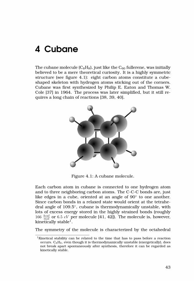
4 Cubane
The cubane molecule (C8H8), just like the C60 fullerene, was initiallybelieved to be a mere theoretical curiosity. It is a highly symmetricstructure (see figure 4.1): eight carbon atoms constitute a cube-shaped skeleton with hydrogen atoms sticking out of the corners.Cubane was first synthesized by Philip E. Eaton and Thomas W.Cole [37] in 1964. The process was later simplified, but it still re-quires a long chain of reactions [38, 39, 40].
Figure 4.1: A cubane molecule.
Each carbon atom in cubane is connected to one hydrogen atomand to three neighboring carbon atoms. The C-C-C bonds are, justlike edges in a cube, oriented at an angle of 90 to one another.Since carbon bonds in a relaxed state would orient at the tetrahe-dral angle of 109.5, cubane is thermodynamically unstable, withlots of excess energy stored in the highly strained bonds (roughly166 kcal
mol or 6.5 eV per molecule [41, 42]). The molecule is, however,kinetically stable1.
The symmetry of the molecule is characterized by the octahedral
1Kinetical stability can be related to the time that has to pass before a reactionoccurs. C8H8, even though it is thermodynamically unstable (energetically), doesnot break apart spontaneously after synthesis, therefore it can be regarded askinetically stable.
43
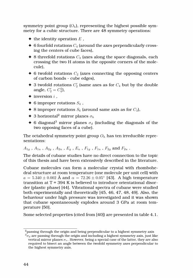
symmetry point group (Oh), representing the highest possible sym-metry for a cubic structure. There are 48 symmetry operations:
F the identity operation E ,
F 6 fourfold rotations C4 (around the axes perpendicularly cross-ing the centers of cube faces),
F 8 threefold rotations C3 (axes along the space diagonals, eachcrossing the two H atoms in the opposite corners of the mole-cule),
F 6 twofold rotations C2 (axes connecting the opposing centersof carbon bonds - cube edges),
F 3 twofold rotations C ′2 (same axes as for C4 but by the double
angle, C ′2 = C2
4 ),
F inversion i ,
F 6 improper rotations S4 ,
F 8 improper rotations S6 (around same axis as for C3),
F 3 horizontal2 mirror planes σh
F 6 diagonal3 mirror planes σd (including the diagonals of thetwo opposing faces of a cube).
The octahedral symmetry point group Oh has ten irreducible repre-sentations:
A1g , A1u , A2g , A2u , Eg , Eu , F1g , F1u , F2g and F2u .
The details of cubane studies have no direct connection to the topicof this thesis and have been extensively described in the literature.
Cubane molecules can form a molecular crystal with rhombohe-dral structure at room temperature (one molecule per unit cell) witha = 5.340 ± 0.002 Å and α = 72.26 ± 0.05 [43]. A high temperaturetransition at T = 394 K is believed to introduce orientational disor-der (plastic phase) [44]. Vibrational spectra of cubane were studiedboth experimentally and theoretically [45, 46, 47, 48, 49]. Also, thebehaviour under high pressure was investigated and it was shownthat cubane spontaneously explodes around 3 GPa at room tem-perature [50].
Some selected properties (cited from [40]) are presented in table 4.1.
2passing through the origin and being perpendicular to a highest symmetry axis3σd are passing through the origin and including a highest symmetry axis, just like
vertical mirror planes σv. However, being a special case of the latter, they are alsorequired to bisect an angle between the twofold symmetry axes perpendicular tothe highest symmetry axis.
44

Table 4.1: Properties of C8H8.
Property ValueC-C distance 1.5727± 0.0019 ÅC-H distance 1.118± 0.008 Å
Colortransparent (up to
200 nm)Toxicity nontoxic
Stabilityinert to light, water,
air
Decompositionvery slow, for
T > 220CDensity 1.29 g
cm3
Vapour pressure (at 25C) 1.1 mmBoiling point ≈ 133CMelting point 130− 131CSolubility ≈ 18 wt%Heat of formation [41] ([51]) +144 kcal
mol (+159 kcalmol )
Strain energy [41] ([51]) 166 kcalmol (181 kcal
mol )
45

5 C60-cubane, a rotor – statorcompound
In previous chapters the C60 and C8H8 molecules were presented.Both structures are highly symmetric and their shapes are comple-mentary to one another: C60 molecules are convex, nearly spheri-cal, and cubane faces are slightly concave, due to the presence ofhydrogen atoms on the corners. A suggestion to combine these twocomponents was brought up by Yildirim et al. [44] in 1997, but itwas not until 2005 when it was first realized by Pekker with co-workers [52].
5.1 Crystal structure
The C60·C8H8 heteromolecular crystals have 1:1 stoichiometry. Toproduce C60-cubane both ingredients are mixed in an aromatic so-lution and the crystals can be produced either by slow evaporationof solvent or by adding a precipitant to the solution, e.g. isopropylalcohol. Fullerenes are forming a f.c.c. lattice with cubane placedin the octahedral voids (see figure 5.1) and also forming a f.c.c.lattice. Altogether the crystal structure can be compared to therocksalt structure. At room temperature C60 molecules are freelyrotating, while cubane molecules remain orientationally fixed, play-ing a role of molecular bearings. This unusual dynamics is a resultof effective molecular recognition (match of surfaces) between thetwo molecules’ shapes and symmetry.
The presence of cubane molecules in octahedral voids of the latticeleads to a lattice expansion as compared to the C60 parent lattice.A perfect match between each of the cubane faces and the sur-rounding fullerene molecules provides enough attraction betweenthe molecules to keep the solid together, and at the same time theintermolecular interaction is so weak, that the constituents behavealmost as if the other molecules were not there.
Up to date, the family of rotor-stator compounds was broadened byusing higher fullerenes (C70, C76, C84) in place of C60, or by sub-stituting cubane by its derivative (C60·C8H6(C2H)2) [52, 53]. Those
46

(a) A space-fill view ofthe rotor-stator phaseof C60-cubane. Rotat-ing fullerenes occupy thef.c.c. lattice sites andstatic cubanes are inoctahedral voids in be-tween.
(b) The position ofcubane in an octahedralvoid of the f.c.c. cell.Concave outer facesshow the perfect matchbetween cubane and thesurrounding fullerenes.
(c) Stator-rotor ar-rangment of fullerenemolecules (spheres) inthe molecular bearingsof cubane.
Figure 5.1: C60-cubane, a rotor-stator compound. (a) and (b)Reprinted (adapted) by permission from Macmillan Pub-lishers Ltd: Nature Materials vol. 4, page 764-767, copy-right 2005.
new heteromolecular compounds have different crystal structures,depending on the molecular recognition between the components.
5.2 Experimental studies
The powder X-ray diffraction study presented in the supplemen-tary material for [52] indicates the Fm3m symmetry space group(f.c.c.) with a lattice constant a = 14.742 Å, and the unit cell volumeequal 3204 Å3. Our results obtained for the pristine material (see fig-ure 5.2) are in good agreement with this original report. The idealpeak positions for a f.c.c. lattice with a lattice constant as in [52]are marked on the figure by vertical lines. The inset presents acomparison of XRD data on C60·C8H8 compound and pristine C60.The downshift of all the visible peaks in case of the compound in-dicates the lattice expansion (caused by the presence of cubanes)and the 200 reflection, which is absent in pure C60, appears1.
Raman studies of pristine C60·C8H8 were performed with all fourlasers listed in table 1.1. The results in the rage of 100− 1800 cm−1
1The 200 reflection is not forbidden in case of C60, as it would be in case of diamond.The absence of the diffraction peak is caused by exact coincidence of the peakposition with a zero of the molecular X-ray form factor function (see section 2.4.3).
47
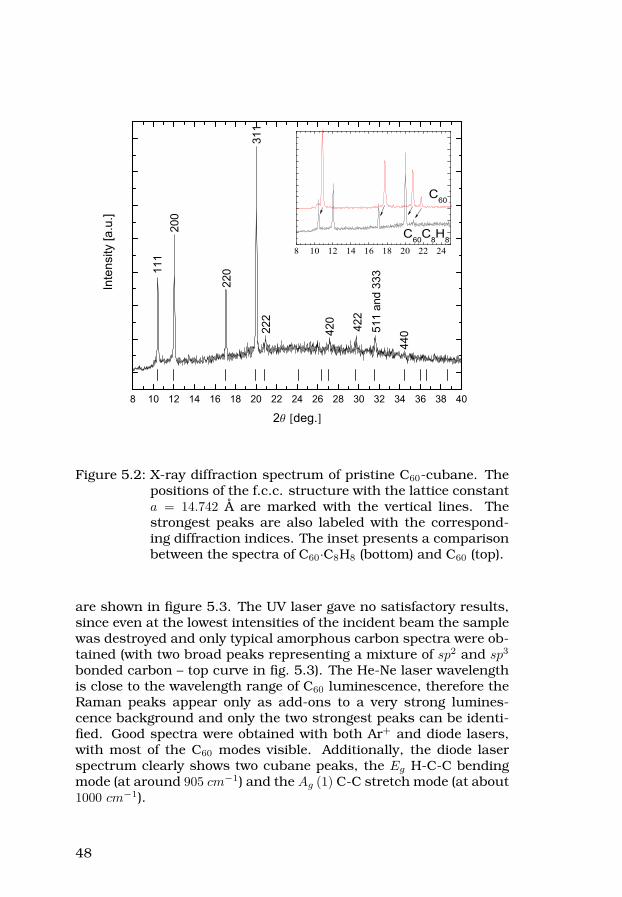
8 10 12 14 16 18 20 22 24 26 28 30 32 34 36 38 40
8 10 12 14 16 18 20 22 24
C60
C60C8H8
In
tens
ity [a
.u.]
2 deg.
111
200
220
311
222
420
422
511
and
333
440
Figure 5.2: X-ray diffraction spectrum of pristine C60-cubane. Thepositions of the f.c.c. structure with the lattice constanta = 14.742 Å are marked with the vertical lines. Thestrongest peaks are also labeled with the correspond-ing diffraction indices. The inset presents a comparisonbetween the spectra of C60·C8H8 (bottom) and C60 (top).
are shown in figure 5.3. The UV laser gave no satisfactory results,since even at the lowest intensities of the incident beam the samplewas destroyed and only typical amorphous carbon spectra were ob-tained (with two broad peaks representing a mixture of sp2 and sp3
bonded carbon – top curve in fig. 5.3). The He-Ne laser wavelengthis close to the wavelength range of C60 luminescence, therefore theRaman peaks appear only as add-ons to a very strong lumines-cence background and only the two strongest peaks can be identi-fied. Good spectra were obtained with both Ar+ and diode lasers,with most of the C60 modes visible. Additionally, the diode laserspectrum clearly shows two cubane peaks, the Eg H-C-C bendingmode (at around 905 cm−1) and the Ag (1) C-C stretch mode (at about1000 cm−1).
48

200 400 600 800 1000 1200 1400 1600 1800
200 400 600 800 1000 1200 1400 1600 1800
200 400 600 800 1000 1200 1400 1600 1800
200 400 600 800 1000 1200 1400 1600 1800
255 260 265 270 275 280
Raman shift [cm-1]
Diode
Inte
nsity
[a.u
.]
Ar+
HeNe
HeCd
Figure 5.3: Raman spectra of pristine C60·C8H8 obtained with diode,He-Ne, Ar+ and He-Cd lasers (as labeled). On the diodelaser figure cubane peaks are marked with vertical linesand the inset presents the splitting of the Hg(1) mode.
Using a Raman spectrometer it was also possible to measure the lu-minescence of pristine C60·C8H8. The results obtained between 77 Kand room temperature using He-Ne and Ar+ lasers are presented in
49

Paper VII. Already the room temperature studies show that the lu-minescence of the rotor-stator compound in the visible-to-near-IRrange is mainly due to C60 molecules; the spectra are very similarto the luminescence of pure C60 – consisting of a very broad peak,with the maximum intensity at a wavelength of about 730 nm.
The low temperature PL studies on C60·C8H8 were reported onlyrecently (Paper VII), and I regret that there was not enough timeyet to analyze them in more detail (i.e. to separate and identifythe transitions). The results look interesting, evidencing that C60 inthe compound with cubane is actually less affected by neighboringmolecules than it is in a pristine C60 solid. Therefore PL spectra ofC60·C8H8 are sharper and much better resolved at 77 K, possiblyeven allowing for meaningful fitting and mode assignment which incase of pure C60 requires much lower temperatures.
50
6 Carbon nanotubes
There is a number of sources which summarize the current state ofknowledge about carbon nanotubes. Therefore, I decided to providehere only a very basic and brief introduction “for beginners”. For amore detailed and broader overview see e.g. [3, 54, 55, 56, 57, 58]. Iwould also recommend to have a look at the web page about carbonnanotubes by prof. David Tománek1.
The observation of carbon nanotubes (at that time called “micro-tubules of graphitic carbon”) was first reported by prof. SumioIijima in 1991 [59], and the first observed nanotubes had severalgraphitic walls each. Two years later the first ever synthesis ofsingle-wall carbon nanotubes was reported [60, 61].
6.1 Structure
Carbon nanotubes are easiest defined as rolled-up fragments ofgraphene sheets (hexagonal “chicken wire” of carbon atoms, seefigure 6.1 (a)). Nanotube diameters are usually in the range of sev-eral nanometers (thus the name), but their lengths can be even afew orders of magnitude longer. Because of such high aspect ratiosthey are in practice one-dimensional objects.
Naturally, the pieces have to be “tailored” in such a way that theedges to be put together must allow for recovering periodicity aroundthe circumference of the tube, once folded. The structure and pro-perties of each particular nanotube depend strongly on its chirality,that is the orientation of the chiral vector Ch (see fig. 6.1 (b)) withrespect to the graphene unit vectors a1 and a2. The unit vectorsconstitute a convenient coordinate system for our considerations.The chiral vector connects the (arbitrarily chosen) origin atom, atthe (0, 0) position, with an atom chosen to coincide with the originon the circumference of the nanotube, at a position (n, m) in thegraphene sheet. In consequence, the chiral vector itself has to be alinear combination of the two lattice unit vectors, given as:
Ch = na1 + ma2
1The Nanotube Site: http://nanotube.msu.edu/
51

(a) graphene sheetfolded into a nanotube
(b) Chiral vector on a graphene sheet. The shaded area canbe rolled to a (3,2) nanotube.
Figure 6.1: From graphene to carbon nanotube [62].
Each nanotube is uniquely identified by its chiral vector coordi-nates, (n, m). Two special cases, when the chiral vector is pointingalong one of the high symmetry directions in the graphene sheet,were named as zig-zag and armchair, due to the shapes which canbe traced along the circumferences of such nanotubes (as indicatedin fig. 6.1 (b)). In a zig-zag configuration Ch is parallel to one ofthe unit vectors of the graphene lattice, and the nanotube can bedescribed by (k, 0), where k is an integer. In case of the armchairconfiguration, Ch points exactly between the unit vectors and ananotube is described by (k, k). All other nanotube structures arecalled chiral. Because of the high symmetry of a graphene sheet,each possible nanotube structure can be created using chiral vec-tors “attached” to the lattice points lying within any π
6 angular sliceof the plane starting at the origin. Traditionally, a fragment re-stricted between the a1 and the a1 + a2 directions is chosen. Forcompleteness, one should also mention the definition of a chiralangle θ (see fig. 6.1 (b)), which is an angle between a1 and Ch, andassumes values between 0 (zig-zag) and π
6 (armchair). Examples ofnanotubes with different chiralities are shown in figure 6.2.
A unit cell of a nanotube is a cylinder with circumference given bythe length of the chiral vector, and length defined by a so-called Tvector, perpendicular to Ch, but attached at the same origin, and
52

(a) (10,10), armchair (b) (18,0), zig-zag (c) (15,10), chiral
Figure 6.2: Nanotube chirality [62].
finishing at the nearest lattice point intersected with its direction.
If we denote the length of each graphene unit vector as a, it is easyto show that the diameter of an arbitrary (n, m) nanotube will begiven by:
d =a
π
√n2 + m2 + nm
Let us now consider the stability of a nanotube with a given diam-eter. Carbon atoms in graphite are sp2 covalently bonded, each toits three nearest neighbors in a plane. When a graphene sheet isbent the carbon bonds are stressed and gain a degree of sp3 charac-ter, but are still far from a tetrahedral arrangement. Naturally, thebonds on nanotubes with the smallest diameters should be moststrained, which makes such nanotube structures less stable. In-deed, such extremely thin nanotubes are not observed, unless in-side of bigger tubes, supporting them from the outside.
The simplest nanotubes, as described above, are single-walled car-bon nanotubes (SWNT). Such nanotubes can be stacked one insideof another, creating multi-walled nanotubes (MWNT), with the spe-cial case of double-walled carbon nanotubes (DWNT).
53

Introduction of defects in the hexagonal lattice arrangement (pen-tagons or heptagons) locally changes the curvature of the surface[63]. The tubes can be closed at the ends by half-fullerene caps,by including six pentagons at each end (or 6 + x pentagons and xheptagons). The defects on the nanotube side walls are weakeningthe construction, but they also allow for creating bends, Y-shapedconnections, etc.
6.2 Synthesis
Carbon nanotubes can be synthesized by various methods, but un-fortunately, so far none of them is selective enough when it comesto chirality. Nanotubes produced in an electric arc discharge be-tween two graphite electrodes [59], one of which is doped with acatalyst, are only one component of carbon soot containing variouscarbon structures. Similar results are obtained by laser ablationof a graphite target. On the other hand, it is possible to producecarbon nanotubes by chemical vapour deposition (CVD) methods,which have been up to date much refined. The temperatures re-quired for CVD nanotube synthesis are generally lower than in theprevious methods, and it is easier to control and modify the pro-cess in order to tune the product properties. Generally speaking,nanotubes grown by CVD methods form at the interfaces of catalystparticles, whose sizes and positions can in principle be controlled.In this way, CVD can be used for growing aligned nanotube forestsor separated nanotubes at specific locations.
In any case, as-produced material requires further purification inorder to obtain catalyst free nanotube samples with well definednanotube geometries (SWNT, DWNT, MWNT, within a specified rangeof diameters, etc.). There are still no effective methods of nanotubeseparation depending on their type of electric conduction.
During my graduate studies I have only been using nanotubes pro-duced by other research groups or commercial companies.
6.3 Highlighted properties
6.3.1 Mechanical properties
In the context of this thesis the excellent mechanical properties ofnanotubes play a leading role. Nanotubes are very elastic, withYoung’s modulus estimated in the TPa range (e.g. 1.25 TPa [64]),
54

and can withstand even very severe deformations [65]. Even thoughthe maximum observed elastic elongation of a nanotube is so far inthe range of 5-6% [66, 67] (while theoretically predicted to be muchhigher [68]), a nanotube will deform rather than break; nanotubeswere reported to extend to 280% of the initial length before breaking[69]. The tensile strength of nanotubes (i.e. the maximum force percross-sectional area that a material can withstand), theoreticallypredicted at ~300 GPa, in reality is limited by presence of defects.Still, even though the experimentally measured tensile strengthsof MWNTs reach “only” about 63 GPa [70], it is still 1-2 orders ofmagnitude higher than for other materials (e.g. steel). No wonderthat carbon nanotubes are already used as a strengthening ingre-dient in composite materials, obtaining excellent results even whena very small amount is added (see e.g. [71]).
Nanotubes were used for production of very strong ribbons [72],fibers [73], yarns [74, 75, 76] and even self-supporting, transparentmacroscopic sheets [77], a stunning do-it-yourself from a nanotube“forest” by simply sticking a post-it note and pulling2.
The strength of macroscopic elements made of carbon nanotubes isstill far from what could be expected, and so far carbon nanotubesare outrun by Kevlar. I would suppose, however, that with somemore material engineering the limits can be pushed much farther.Similar reasoning reanimated serious scientific discussions abouta near-fictional idea of a space elevator (proposed already in the1960’s), postulating its realization based on carbon nanotube ropes(see e.g. [78, 79]).
6.3.2 Electrical properties
Nanotubes can be metallic or semiconducting, and their band struc-ture depends on the chirality. One can explain the variation byconsidering a nanotube as a direct relative of a graphene sheet. Incase of graphite, being a zero-gap semiconductor, the valence andconduction bands meet in the corners of the hexagonal Brillouinzone, at so-called K points. A graphene sheet can be considered asan infinite 2D plane, which means that no additional constraintsapply, and graphite at finite temperatures is a good conductor. Ananotube can be considered to be infinite only in one dimension,while around the circumference it is finite, thus introducing addi-tional, periodic boundary conditions and causing confinement ef-
2If you are still not convinced that the mechanical properties of carbon nanotubeshave no equals you should have a look especially at reference [77] and the accom-panying material. What other material can support a mass 50 000 times greaterthan its own?
55

fects. Solutions for allowed k-states in each case are dependent onthe length of the chiral vector, but constitute a discreet set of linesintersecting the graphene Brillouin zone. If there exists a solutionintersecting with the K point, the tube is metallic, otherwise a gapis present in the density of states at the Fermi level and the tubeis semiconducting. The dependence on the chiral vector is equiva-lent to the dependence on its coordinates, (n, m). It is possible toclassify nanotubes as metallic or semiconducting by checking thevalidity of the following equation, where i is an integer:
n−m = 3i
If this equation is satisfied, the tube is metallic.
The one-dimensional character is evident in the electric properties,since van Hove singularities, as shown in figure 6.3, appear in thedensity of states of a nanotube [80].
-3 -2 -1 0 1 2 3 -3 -2 -1 0 1 2 3
(10,3)
Energy [eV]
Den
sity
of s
tate
s
Energy [eV]
(9,0)
Figure 6.3: Density of states – examples of a semiconducting (left)and a metallic (right) nanotube, with chiralities [81].Energy scale has a zero at the Fermi energy.
Finally, due to the strong coupling of electrical properties to nano-tube structure and chirality it might be relatively easy to adjust theresponse of individual tubes, since band gap values can possibly bechanged by strain [82].
56

6.3.3 Optical properties
In this section I would like to focus on Raman spectroscopy on car-bon nanotubes, highlighting the features important for my studies.
Each nanotube has a very distinct set of allowed transitions, be-cause of the sharp features (van Hove singularities) in the one-dimensional density of states. In consequence, Raman scatteringoff carbon nanotubes is a resonance phenomenon and can providevery detailed information about the samples3. A typical Ramanspectrum of a sample containing single-wall carbon nanotubes isshown in figure 6.4.
200 400 600 800 1000 1200 1400 1600 1800
Ram
an in
tens
ity [a
rb. u
nits
]
Raman shift [cm-1]
RBM D
G
Figure 6.4: An example of a Stokes side in Raman spectrum ofSWNT.
There are three well visible peak groups in the spectrum. Thefirst one, at low Raman shift values, is a set of peaks represent-ing the frequencies of radial breathing modes (RBM) for some ofnanotubes in the sample, those resonant with the excitation laser3A resonance occurs whenever the incoming photon energy is compatible with the
energy difference between two van Hove singularities, on the opposite sides ofthe Fermi energy. Due to a low DOS between the van Hove singularities thecontributions from the latter completely dominate in the Raman spectrum.
57

wavelength. At about 1300 cm−1 there is a so-called D-band, whichcan be correlated with the amount of defects in the sample. Around1600 cm−1 there is the G-band (“graphitic”), Finally, second orderscattering peaks (overtones) can be observed at higher Raman shiftvalues (not shown in figure 6.4). It is also worth mentioning, thatcarbon nanotubes are a rare example of materials for which Stokesand anti-Stokes spectra may qualitatively differ [83].
Based on Raman spectra it is possible to estimate the diameters ofthe nanotubes present in the sample, as well as to identify theirchiralities and discriminate between metallic and semiconductingtubes. It so happens, that energies of the RBM for nanotubes withgiven chiralities plotted versus the nanotube diameter form a pat-tern of curved stripes, as shown in figure 6.5, known as the Katauraplot [84].
0.0 0.5 1.0 1.5 2.0 2.5 3.0 3.5 4.0 4.5 5.00.0
0.5
1.0
1.5
2.0
2.5
E [e
V]
Nanotube diameter [nm]
Ar+
diodeHe-Ne
Figure 6.5: Kataura plot. Each circle represents a nanotube with acertain chirality [81]. Full circles correspond to metallicand open circles to semiconducting tubes. Horizontallines show the energies of our three Raman lasers.
The RBM region of the Raman spectra of a carbon nanotube sam-ple obtained with different excitation lasers will vary. The visiblepeaks can be attributed to nanotubes in which transition energiesare resonant with the laser light (i.e. those points in fig. 6.5 whichare crossed by the laser “line”). If the approximate nanotube dia-meter distribution is known (e.g. from TEM studies) it is possible toidentify the chirality of each nanotube visible in the Raman spec-trum.
58
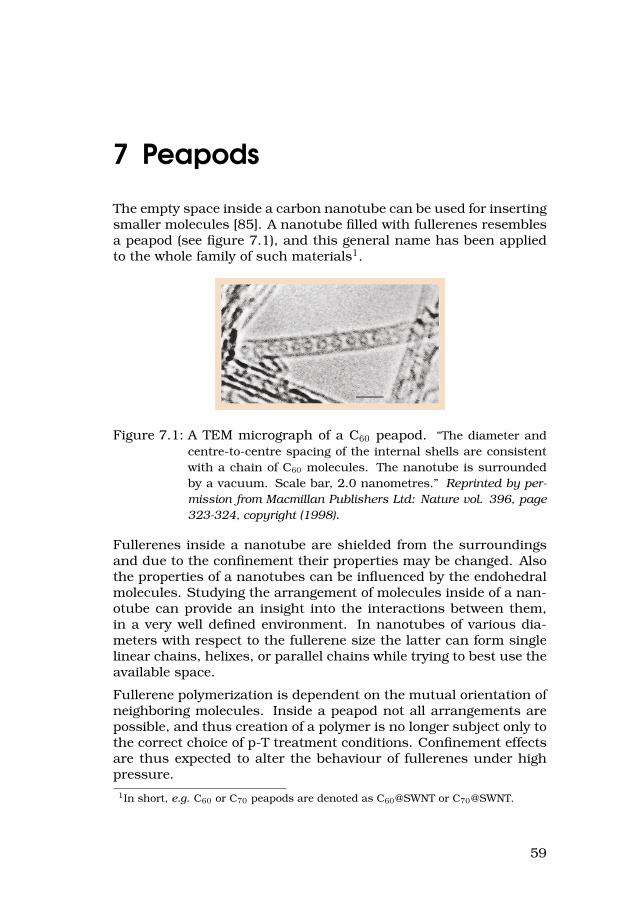
7 Peapods
The empty space inside a carbon nanotube can be used for insertingsmaller molecules [85]. A nanotube filled with fullerenes resemblesa peapod (see figure 7.1), and this general name has been appliedto the whole family of such materials1.
Figure 7.1: A TEM micrograph of a C60 peapod. “The diameter andcentre-to-centre spacing of the internal shells are consistentwith a chain of C60 molecules. The nanotube is surroundedby a vacuum. Scale bar, 2.0 nanometres.” Reprinted by per-mission from Macmillan Publishers Ltd: Nature vol. 396, page323-324, copyright (1998).
Fullerenes inside a nanotube are shielded from the surroundingsand due to the confinement their properties may be changed. Alsothe properties of a nanotubes can be influenced by the endohedralmolecules. Studying the arrangement of molecules inside of a nan-otube can provide an insight into the interactions between them,in a very well defined environment. In nanotubes of various dia-meters with respect to the fullerene size the latter can form singlelinear chains, helixes, or parallel chains while trying to best use theavailable space.
Fullerene polymerization is dependent on the mutual orientation ofneighboring molecules. Inside a peapod not all arrangements arepossible, and thus creation of a polymer is no longer subject only tothe correct choice of p-T treatment conditions. Confinement effectsare thus expected to alter the behaviour of fullerenes under highpressure.1In short, e.g. C60 or C70 peapods are denoted as C60@SWNT or C70@SWNT.
59

8 Concept material:C60-nanotube co-polymer
From the perspective of material science applications each form ofcarbon has its advantages and disadvantages. Diamond, being thehardest material known, requires extreme pressure and temper-ature to be produced. It has also a rather high density, whichwould cause the elements hypothetically made of diamond to berather heavy. A question may be asked if it would be possibleto create a material almost as hard, but at the same time muchlighter? The strength of diamond originates in its tetrahedral sp3
bonding. Graphene bonds, sp2 hybridized, are even stronger, butonly within the plane. Graphite is formed by stacking such “hard”planes loosely on the top of each other making the material as awhole rather soft. The bonds on carbon nanotubes and fullereneshave a mixed sp2 − sp3 character, because graphene is bent to formthem. These kind of structures are hollow inside, and thus ex-tremely light-weight. Considering their mechanical properties, atthe nanoscale they are thus ideal candidates for superhard mate-rials. Unfortunately, nanometer sized building blocks are not veryuseful for macroscopic constructions if they cannot be bound to-gether strongly enough. Nanotubes are indeed very difficult to bind,since they are very inert, especially on the sidewalls. C60, on thecontrary, can be covalently bonded, as was already mentioned insection 2.4.1 and chapter 3. The tetragonal polymeric phase of C60
could be a good candidate for a macroscopic material, but unfortu-nately the molecules tend to bind in small domains, which are notwell connected together. Because of that, bigger pieces of materialare brittle, breaking between the superhard grains.
At this point I have decided to try taking advantage of C60’s reac-tivity and combine it with carbon nanotubes to provide a strength-ening skeleton. The idea of material reinforcement by adding car-bon nanotubes is not new in itself, but I dreamed of creating acarbon-only material, a light almost-diamond. In an ideal case,well dispersed, elastic carbon nanotubes would be surrounded byC60 polymer, and at some places also covalently bonded to it. Ananoscale version of a “reinforced concrete”, which I would call afullerene-nanotube co-polymer.
60

I have made several attempts to realize this idea, and some of theresults are promising. This work is still unpublished, but I decidedto include parts of it in this thesis. Since my co-polymer candidatesamples were not (yet) characterized by high resolution transmis-sion electron microscopy (HR-TEM), I cannot say for sure if I suc-ceeded to create bonds between C60 and nanotubes. Please have alook at chapter 14 for the rest of this story, and some suggestionsabout how it can be continued.
61


Part II
Selected experimentalparticulars and results
63


9 Studies of tetragonallypolymerized C60 crystals
9.1 Synthesis
9.1.1 Crystal growth
The initial cause for this study was to characterize the tetragonalpolymer C60 phase on well oriented surfaces, like crystal faces. C60
crystals were grown from 99.98% pure C60 powder (Term, BerkeleyUSA) by vacuum sublimation inside a two-zone oven. A 25-30 cmlong piece of ≈6 mm in internal diameter glass capillary was cutand sealed at one end using a gas flame. When choosing the tubeone has to keep in mind that the melting point of the glass it ismade of should exceed 650C. Heat-treatment above 100C (e.g.in a vacuum oven) removes water that might be adhered to thesurface of the capillary. The tube is then left to cool down andput inside an argon-filled glovebox. If needed, the water removingheat treatment can be repeated. About 60 mg of high purity C60
powder (stored under Ar gas atmosphere and shielded from light)is loaded into the capillary. The tube is then turned vertically, andthe powder falls down to the sealed end. The open end of the glasstube is attached to a vacuum pump by a rubber hose. The capillaryis pumped on for a few minutes and sealed, still under dynamicvacuum, by flame melting. About 5 cm of the tube length has tobe sacrificed, since the heat from the flame would otherwise meltthe rubber hose. While the glass begins to melt, it is easy to sealthe capillary, by slow turning and pulling, which causes the glasswalls to collapse without creating any openings. Care should betaken to warm up the whole circumference of the tube at the samerate, rather than melting one side at a time. In this way we get C60
powder sealed inside the glass tube under vacuum, and the tubelength (20-25 cm) fits well inside the two-zone furnace. Oxygen-freeconditions ensure that further heating, required for sublimation tooccur, will not cause burning. Once again, the powder is gentlyshaken down, and the tube is then turned to a horizontal position,with most of the powder near one of the tube ends. The tube canbe gently tapped to distribute the powder evenly over about 30% of
65

the tube’s length. At this point the sealed capillary can be insertedinto the furnace.
To start with, the temperature in the furnace is set to 600C at oneplace and 550C at the other. The capillary is inserted in such away, that the powder is on the colder side. Treatment under suchconditions for 12-24 hours ensures that all the C60 powder stuckon the walls of the capillary sublimates back into the “source” side,thus cleaning the future crystal growth area. Afterwards, the tubeis very carefully removed, and inserted back to the furnace, but inthe opposite orientation, in order to start the crystal growth. Thetemperature of the“source” side, containing the C60 powder, is nowset to 610C, and the crystallization side to 500C. From now on,C60 sublimates from the hot side and starts to settle in the colderend, seeding the crystal growth. The growth continues for about amonth, until the crystals reach the desired size or until all C60 pow-der is used. The size and shapes of grown crystals depend on theactual temperature values in the furnace and the gradient betweenthem. The crystals grown in our experiments were up to ≈1 mm inthe biggest dimension, and had a great majority of 111 faces. Themost common crystal shape was a flat, truncated triangle. It wasalso possible to find a few crystals with small 100 planes.
If the crystals were not to be used immediately, they were storedin a sealed glass tube, as-grown, lying on a shelf in the office. Inconsequence of such storage the outer surface of C60 crystals couldbecome photopolymerized. In order to break any such accidentalpolymeric bonds the crystals were annealed at 500 K for 3 hours,still under vacuum, before the tube was opened.
9.1.2 Polymerization
hp-hT polymerization of our single crystals to tetragonal phase un-expectedly proved to be a rather difficult task. We had carried out aconsiderable number of unsuccessful attempts before we managedto obtain several polymerized crystals, clean enough to be charac-terized. We have tried high pressure treatment both with solid andliquid pressure-transmitting media, with annealing conditions cho-sen to be 2 GPa and 700 K, to be kept for 4 hours. Each experimentstarted by applying a pressure of 0.5 GPa, followed by heating andfinal pressurization. If the setup did not fail before annealing wascompleted, the temperature and pressure were quenched. In caseof liquid media a small heater power was kept to maintain the tem-perature at just below 100C until the pressure fell below 1 GPa toprevent the solidification of a medium, and at the same time not todepolymerize the crystals.
66

Since the experiments were aimed at characterization of the te-tragonal polymer on well defined crystal faces we required from apressure medium to be easily removed from the sample and notto destroy the surface. One of the ideas was to use NaCl as apressure-transmitting medium. It should then be easy to recoverthe samples, since salt is water soluble, in contrast to tetragonalC60. A big disadvantage, though, is that salt crystallites could crushthe surfaces of the samples. One experimental approach has beenmade, nevertheless. The C60 crystals were placed on a Cu supportwith a wedge, and NaCl was slowly crystallizing on their surfacesby drop casting of a warm water solution. The sample supportwas then placed inside a standard pyrophyllite oven and coveredup with more, finely ground NaCl. Unfortunately, the C60 crystalfaces were crushed during the high pressure treatment, despite theabove precautions.
In another experimental series, we have used various silicone oilsas a pressure-transmitting medium: 1) a rather light, low viscosityoil, 2) a heavier, higher viscosity silicone oil, and 3) a mixture ofthe two latter. A few crystals were selected for each experiment andloaded into a standard glass oven, same as shown in fig. 1.1 (b).Unfortunately, none of these pressure media was stable enough atthe highest temperatures. Each time a considerable gas pressurewas present in the pressure cell after the load was released, andthe crystals were embedded into a hard silicone-polymer matrix.The excess gas could at any time lift off the top piston and shoot itupwards, which posed a danger for anyone standing close by. Weallowed several hours for a slow gas pressure release via the tinyvoid space between piston and cylinder, and then carefully openedthe pressure cell. Polymerization of silicone oil around the crystalshas filled the whole space inside of the glass oven with a glassy,hard solid. Depending on the oil type the silicone polymer colorvaried from shiny black to almost transparent. It was not possibleto dissolve it even by long sonication in silicone-specific solvents,nor to melt it by heat treatment up to 130C (which would alreadybe above the C60 depolymerization temperature). Surprisingly, wehave not encountered this kind of behaviour of silicone oil in otherexperiments at similar conditions. We can only try to explain itby accidental short-time overheating (since no polymer was foundoutside the ovens, where temperature was definitely lower).
In the final experimental series we decided to use petroleum ether(boiling point 80-100C under normal pressure) later substitutedby petroleum benzine (140-180C). Under high pressure the boil-ing temperatures should shift towards much higher values, we didnot know, however, if sufficiently so. A considerable amount ofpetroleum ether decomposed to a gas, forcing us to take the same
67

precautions as with the silicone oil, but petroleum benzine wasrather stable, with only small amounts of gas present in the cellafter treatment at 2 GPa and 700 K. More importantly, both medialeft C60 crystals covered only by a thin layer of porous carbon soot(without a well defined Raman signal), which was easy to removecompletely by a short sonication in pentane. In this way we havefinally succeeded to polymerize several C60 single crystals and wecould proceed to their characterization.
9.2 Characterization
All the successfully polymerized samples with clean surfaces werecharacterized by Raman spectroscopy. Also, some attempts weremade at AFM studies of the molecular arrangement of C60, but dueto the high surface roughness of the high-pressure treated samplesthe results were rather unsatisfactory.
Raman spectra were collected from many spots on each sample.Identification of crystal planes was based on the macroscopic ap-pearance under the optical microscope (shape assessment of stepsand cracks). A few crystals were crushed in order to collect theRaman spectra also on the sub-surface material. The results showthat Raman spectra recorded on different samples or even differ-ent fragments of the same crystal face can vary both qualitativelyand quantitatively, by total intensity, intensity ratios between dif-ferent modes, splitting of some of Hg modes and peak broadening.The number of recorded spectra was sufficient for statistic analysis,but there was no evidence for strict correlation between the type ofspectrum and the crystal face type. Instead, by comparing our re-sults on polymerized single crystals with results for C60 nanorodswe have concluded that the differences may correlate to variouspolymer domain sizes and strains . The results of this study weredescribed in Paper IX.
The tetragonal C60 single crystal project as a whole consumed avery long time, much longer than expected. Not even counting thethree crystal growth rounds (each taking a few weeks, but partlyoverlapping with other activities), it took over half a year to succeedwith the hp-hT treatment and another few months in the darkness,characterizing the samples by Raman spectroscopy.
68
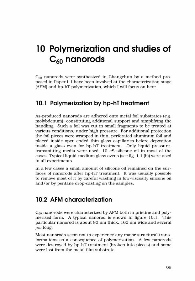
10 Polymerization and studies ofC60 nanorods
C60 nanorods were synthesized in Changchun by a method pro-posed in Paper I. I have been involved at the characterization stage(AFM) and hp-hT polymerization, which I will focus on here.
10.1 Polymerization by hp-hT treatment
As-produced nanorods are adhered onto metal foil substrates (e.g.molybdenum), constituting additional support and simplifying thehandling. Such a foil was cut in small fragments to be treated atvarious conditions, under high pressure. For additional protectionthe foil pieces were wrapped in thin, perforated aluminum foil andplaced inside open-ended thin glass capillaries before depositioninside a glass oven for hp-hT treatment. Only liquid pressure-transmitting media were used, 10 cS silicone oil in most of thecases. Typical liquid-medium glass ovens (see fig. 1.1 (b)) were usedin all experiments.
In a few cases a small amount of silicone oil remained on the sur-faces of nanorods after hp-hT treatment. It was usually possibleto remove most of it by careful washing in low-viscosity silicone oiland/or by pentane drop-casting on the samples.
10.2 AFM characterization
C60 nanorods were characterized by AFM both in pristine and poly-merized form. A typical nanorod is shown in figure 10.1. Thisparticular nanorod is about 80 nm thick, 160 nm wide and severalµm long.
Most nanorods seem not to experience any major structural trans-formations as a consequence of polymerization. A few nanorodswere destroyed by hp-hT treatment (broken into pieces) and somewere lost from the metal film substrate.
69
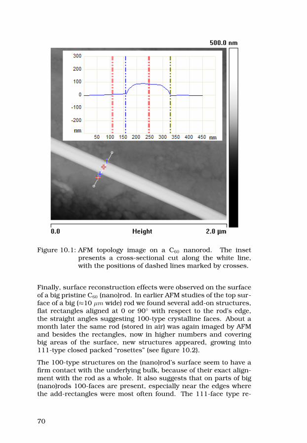
Figure 10.1: AFM topology image on a C60 nanorod. The insetpresents a cross-sectional cut along the white line,with the positions of dashed lines marked by crosses.
Finally, surface reconstruction effects were observed on the surfaceof a big pristine C60 (nano)rod. In earlier AFM studies of the top sur-face of a big (≈10 µm wide) rod we found several add-on structures,flat rectangles aligned at 0 or 90 with respect to the rod’s edge,the straight angles suggesting 100-type crystalline faces. About amonth later the same rod (stored in air) was again imaged by AFMand besides the rectangles, now in higher numbers and coveringbig areas of the surface, new structures appeared, growing into111-type closed packed “rosettes” (see figure 10.2).
The 100-type structures on the (nano)rod’s surface seem to have afirm contact with the underlying bulk, because of their exact align-ment with the rod as a whole. It also suggests that on parts of big(nano)rods 100-faces are present, especially near the edges wherethe add-rectangles were most often found. The 111-face type re-
70
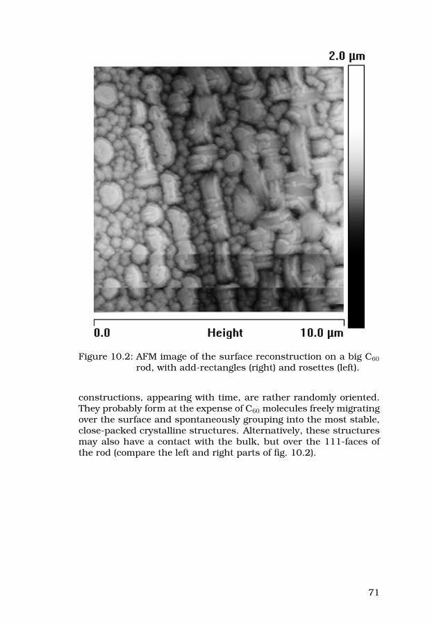
Figure 10.2: AFM image of the surface reconstruction on a big C60
rod, with add-rectangles (right) and rosettes (left).
constructions, appearing with time, are rather randomly oriented.They probably form at the expense of C60 molecules freely migratingover the surface and spontaneously grouping into the most stable,close-packed crystalline structures. Alternatively, these structuresmay also have a contact with the bulk, but over the 111-faces ofthe rod (compare the left and right parts of fig. 10.2).
71

11 In situ measurements ofRb4C60 resistance under highpressure
Due to the high sensitivity of Rb4C60 to air and water, each destruc-tive for the samples, a high pressure study of this material requiresspecial preparations and extra care during the experiments. Thematerial was prepared and partly characterized under vacuum, andall subsequent operations (loading, unloading, further characteri-zation) was taking place either in the Ar filled glovebox or in sealedglass capillaries.
The details of the material production and characterization are al-ready described in Paper VIII. In this chapter I will describe thehigh pressure experiments in more detail. The Rb4C60 materialwas divided into three samples, all of them from the same, pre-viously characterized material batch. Each sample was studied ina separate high pressure experiment, in two cases together with a“control” sample: Rb6C60 or a mixture of RbxC60 with x = 3, 4 and6. Each high pressure experiment consisted of a series of severalisothermic pressure runs and isobaric cooling and heating temper-ature scans. The high pressure experiments lasted from one tothree weeks each.
11.1 Pressure cell design
In the first experiment, the pressure cell was a standard Tefloncell, similar to that in fig. 1.3, just with a machinable glass ceramic(MacorTM) sample holder on a steel support plate instead of a typicaloven. Two type K thermocouples were placed near the sample. Thesample holder had a 0.5 mm deep U-shaped groove machined intothe top side, sized about 10 mm × 1.7 mm, to contain the powdersample. Six contacts, made of 0.2 mm Nickel 200 wire, were fittedto the sample holder, equally spaced and crossing the bottom of thesample groove parallel to one another. Four of the contacts wereto be used for a 4-pole resistance measurement and the other two
72

as backup and additional voltage leads for measuring resistanceover a different fragment of the sample. Away from the sampleholder the nickel contacts were soldered to thicker Cu contact wiresexiting the Teflon cell vertically through its bottom. Rb4C60 powderwas compressed into the sample groove and covered with heat-driedhexagonal BN powder to assure sufficient pressure transmission.The cell was finally filled up with dried talc. In this experimentonly one sample could be studied, and there was no possibility ofheating above room temperature. Liquid nitrogen cooling could beexternally applied to the whole pressure vessel.
In the two later experiments the pressure cell design was adjustedto allow for simultaneous study of two samples and for their heating(see figure 11.1). A glass ceramic sample holder was replaced bysample grooves directly milled into the thick bottom of the Tefloncell, and talc was replaced by Teflon in the role of a p-transmittingmedium filling up the cell.
Figure 11.1: Teflon pressure cell with a heater, designed for in situresistance measurements on two samples under highpressure.
All Teflon surfaces near samples were heat-treated under Ar atmo-sphere in order to remove any adhered water. Nickel wire contacts,four per groove, were made in the same way as before. They wereplaced flat on the cell bottom and near its walls soldered to Cu con-tact wires (brought into the cell vertically through the thick Teflonbottom and also bent flat), see the top view of the cell, fig. 11.1 onthe right. A type K thermocouple was placed between the samplegrooves, so that its metals’ interface was in a position geometricallycorresponding to that of most of the samples’ material. In addition,two Cu wires were brought into the cell and fitted with Cu plugs.
73

The samples were then loaded into the grooves and covered witha thin layer of dried hexagonal BN powder. A 2 mm thick Teflonspacer with opening for the Cu plugs was fitted over the samples.The ends of the Kanthal wire heater1 were fitted to holes drilled inthe Cu plugs, providing a contact with the external power connec-tors, and positioning the heater wire flat on the Teflon surface. Athick Teflon plate was used to fill up the cell, which was eventuallyclosed by a lid. All this was done inside the Ar filled glovebox, withthe Teflon cell already fitted onto the steel bottom piston. A readyand sealed cell was quickly transported between the glovebox andthe hydraulic press, where it was inserted into the high-pressurecylinder, additionally sealed on the top with an indium-covered ringand the top piston and immediately put under a load to prevent anyleaks from the atmosphere.
11.2 Isobaric cooling and heating
As was already mentioned, each high pressure experiment con-sisted of several pressure or temperature scans, so that a collectionof p-T conditions covered in this study forms a network of verticaland horizontal lines, as shown in figure 11.2.
Pressure changes were always applied slowly, when the setup wasnear thermal equilibrium with the surroundings (approximately at,or just below room temperature). Temperature scans were at first(experiment 1) restricted only to liquid nitrogen cooling and slow re-heating back to room temperature, each such cycle taking about 24hours. The cooling was provided externally to the pressure vessel asa whole, by pumping liquid nitrogen onto the top of the high pres-sure cylinder, externally insulated with mineral wool. A Dewar ves-sel containing liquid nitrogen (LN2) was connected to a compressedair feed by a valve with an electronic timer. It was possible to con-trol the cooling rate by adjusting the intervals at which the valvewas opened (≈1 minute) and the pumping duration (typically 10-20seconds). When the valve is opened, the compressed air increasesthe pressure inside of the LN2 vessel, forcing liquid nitrogen to flowthrough an insulated metal hose to the top of the high pressurecylinder.
Near the end of experiment 1 we performed a single heating scan,using an external resistive heater, wound around the high pressure
1The Kanthal wire was tension-formed into the shape of a heater as shown infig. 11.1 on a steel jig, specifically made for this purpose. The formed wire, stillon the jig, was annealed at 100C for about 1 hour to preserve its shape whenlater released.
74

Figure 11.2: Pressure and temperature conditions over all threehigh pressure experiments on Rb4C60, as labeled.
cylinder. Also in experiments 2 and 3 the cooling temperature scanswere completed by 2-4 hours heating above room temperature, us-ing an internal heater (see sec. 11.1). Isobaric temperature runsat some pressures were repeated on different samples, to verify thedata.
Despite allowing for relatively slow temperature changes during thecooling and heating, lubrication and a constant feedback control-ling the load, one has to be aware that small pressure anomaliesare sometimes inevitable. It is mainly because of the differencesin thermal expansion of various materials used and the presenceof volume-affecting phase transitions, e.g. in Teflon around 300-360 K [86], which is sometimes visible in our data, because Teflonis used as a pressure-transmitting medium and thus occupies aconsiderable volume in the pressure cell. As can be seen from fig-ure 11.2 these pressure variations are usually not very significant.Larger deviations, e.g. like the one in experiment 2, on heatingat 2 GPa (see figure) were caused by short power failures for theregulator of the hydraulic pump.
75
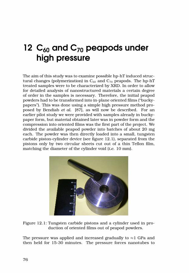
12 C60 and C70 peapods underhigh pressure
The aim of this study was to examine possible hp-hT induced struc-tural changes (polymerization) in C60 and C70 peapods. The hp-hTtreated samples were to be characterized by XRD. In order to allowfor detailed analysis of nanostructured materials a certain degreeof order in the samples is necessary. Therefore, the initial peapodpowders had to be transformed into in-plane oriented films (“bucky-papers”). This was done using a simple high pressure method pro-posed by Bendiab et al. [87], as will now be described. For anearlier pilot study we were provided with samples already in bucky-paper form, but material obtained later was in powder form and thecompression into oriented films was the first part of the project. Wedivided the available peapod powder into batches of about 20 mgeach. The powder was then directly loaded into a small, tungstencarbide piston-cylinder device (see figure 12.1), separated from thepistons only by two circular sheets cut out of a thin Teflon film,matching the diameter of the cylinder void (i.e. 10 mm).
Figure 12.1: Tungsten carbide pistons and a cylinder used in pro-duction of oriented films out of peapod powders.
The pressure was applied and increased gradually to ≈1 GPa andthen held for 15-30 minutes. The pressure forces nanotubes to
76

orient in a plane perpendicular to the pressure axis. As-producedfilms were removed from the press, peeled off the Teflon flakes andcut into smaller pieces, about 2 mm × 2 mm, to be treated underhp-hT conditions. The buckypapers were stiff and easy to handleusing tweezers and could be cut with a razorblade.
Three experiments were performed within the pilot study. In thefirst two, the samples were treated under hp-hT conditions with sil-icone oil as a pressure-transmitting medium. In each experimentthree buckypaper samples were treated: C60@SWNT, C70@SWNTand SWNT for reference. First, a pressure of 0.5 GPa was ap-plied, then the samples were heated to the final annealing tem-perature and finally pressurized to the final pressure (700 K and2 GPa, or 600 K and 1.5 GPa, respectively). The samples wereannealed for 3 hours. The experiments finished with temperatureand pressure quenching, taking care not to solidify the pressuremedium. The last experiment in the pilot study, because of theplanned extreme treatment conditions, was performed with a solidpressure transmitting medium (BN), and with only one sample:C70@SWNT. The sample was treated at 2.5 GPa and 900 K, for 3hours. Since the samples in the first two experiments were inter-calated by small amounts of amorphous, polymerized silicone oilour collaborators signaled that the XRD characterization was diffi-cult. Crystalline BN, however, did not disturb the XRD measure-ments, and thus the main study had to be carried out using a solidpressure-transmitting medium.
In each of the later hp-hT experiments two samples (one C60@SWNTand one C70@SWNT) were treated simultaneously. For each sam-ple, two pieces of the earlier produced and cut peapod buckypaperswere put together. A sketch of the hp-hT oven design used in thisstudy is shown in figure 12.2. The second, outer pyrophyllite cylin-der with a Kanthal wire heater (see the figure) was only applied inthe last two experiments, where we were aiming at the most extremetemperatures, around and above 1000 K.
The annealing conditions and times are summarized in table 12.1.Actually the last experiment, where we have reached almost 1000Cunder pressure of 2.5 GPa, has set a record for hp-hT conditionsever achieved in our setup.
After completed hp-hT treatment the samples were in nearly allcases successfully recovered still in the film form. They were thencarefully packed and expedited to our collaborators for XRD stud-ies.
Finally, we have also tried to characterize the peapod samples byRaman spectroscopy. It was not possible to see the C60 or C70 inside
77

Figure 12.2: Oven design for the hp-hT treatment of C60 and C70
peapod films.
Table 12.1: Treatment conditions for C60@SWNT and C70@SWNToriented films.
Pressure C60@SWNTtemperature
C70@SWNTtemperature
Annealingtime
1.5 GPa 300 K 300 K 3 hours1.5 GPa 573 K 573 K 3 hours1.5 GPa 818 K 824 K 3 hours2.5 GPa 300 K 300 K 3 hours2.5 GPa 573 K 573 K 3 hours2.5 GPa 837 K 803 K 3 hours2.5 GPa 973 K 968 K 30 min.2.5 GPa 1253 K 1253 K 10 min.
the nanotubes with neither Ar+ nor He-Ne laser. We have thereforetried to obtain Raman spectra with a He-Cd laser (in Changchun,China), knowing that with a 488 nm excitation it should be possibleto see the fullerene modes inside the nanotubes, but also thoseattempts failed.
The peapods-under-pressure project as a whole was one of theshortest, and at the same time it was very fruitful. First resultsare presented in Paper V. The samples treated under the most ex-treme conditions are still being analyzed by XRD.
78

13 Polymerization and thephase diagram ofC60-cubane compound
This project has been the main topic for my licentiate thesis. I willpresent some of the details of this study here, but for a broaderdescription please have a look at [1]. Parts of the original text werecondensed and adapted in this chapter.
13.1 Experimental details
The available C60-cubane material was divided into several smallsamples, 3–10 mg each, and deposited on a cylindrical copper sup-port with a raised edge (see figure 13.1). Each sample was thenpartly, or fully, covered by a piece of aluminum foil in order to mi-nimize the intercalation by the pressure-transmitting medium. Thecopper support with the sample was placed inside a pyrophylliteoven, wound with Kanthal wire, to provide resistive heating for thesample.
In the initial experiments three ovens were mounted in the samepressure cell, but due to insufficient thermal insulation it was notpossible to create enough temperature difference between the threesamples, despite independent heaters. That is why later on eachsample was treated in a separate experiment.
The initial aim was to treat several samples at 0 GPa (vacuum),0.5 GPa, 1 GPa and 2 GPa over a range of temperatures. Lateron, the hp-hT study was complemented by a series of experimentsat 600 K and 0.9 GPa, 1.1 GPa, 1.3 GPa and 1.5 GPa. All thesamples were analyzed by means of Raman spectroscopy and X-raydiffraction spectroscopy. To complete the phase diagram C60·C8H8
was also studied by Raman spectroscopy in situ under Ar gas at-mosphere at temperatures down to 77 K, and at room temperature,using a sapphire anvil cell, up to a pressure of 0.8 GPa.
79

Figure 13.1: Sample-containing pyrophyllite oven with a coppersample support for hp-hT treatment of C60·C8H8.
13.1.1 High-pressure – high-temperature treatment
The hp-hT treatment was performed in a piston-cylinder setup de-scribed in section 1.1. Each sample was deposited in a separatepyrophyllite oven, on a copper plate (see fig. 13.1). BN was used asa pressure-transmitting medium. The treatment conditions of theC60·C8H8 samples are listed in table 13.11.
The experiments were designed in the same way for all the sam-ples: the pressure was applied first, followed by heating to the de-sired annealing temperature, annealing for 1–3 hours, and finallyquenching of temperature and pressure. In the first series of ex-periments (at 0, 0.5, 1 and 2 GPa) the heating to the final tem-perature was fast, while during the second series of experimentscare was taken that the heating through the polymerization region,120-180C, was very slow, at a rate of 1 K
min (samples marked intable 13.1 with “slow heating”).
The pressure cells were opened and the samples were extractedfrom the ovens, taking care to minimize any contamination by py-rophyllite, talc or BN. In some cases a minor contamination wasunavoidable, resulting in additional peaks in X-ray diffraction andRaman spectra.
1The sets of three samples marked by †, ?, or ‡ were treated in the same highpressure experiment, in three separate ovens with independent heating. All theother samples were treated each in a separate experiment.
80

Table 13.1: Treatment conditions for C60·C8H8 samples under highpressure and/or high temperature.
pressure [GPa] temperature [K] annealing time [hours]0 300 0 (pristine)0 500 30 620 30 870 1 and 1.5
0.5 383 3 †0.5 410 3 †0.5 460 3 †0.5 750 30.9 600 3 (slow heating)1 417 31 425 3 ?1 466 3 ?1 524 3 ?1 700 31 818 11 875 1
1.1 600 3 (slow heating)1.3 600 3 (slow heating)1.5 600 3 (slow heating)2 426 3 ‡2 499 3 ‡2 601 3 ‡2 700 32 873 1
13.1.2 XRD overview
A collection of XRD spectra for the distinct C60·C8H8 phases is pre-sented in figure 13.2.
Summarizing the XRD data discussion provided in both papers:
F Pristine C60·C8H8 has a f.c.c. structure with a lattice constanta = 14.742 Å. The XRD peaks are sharp, and the (200) peak ap-pears in the spectrum because the expanded lattice parameter(as compared to C60) causes a downshift of all peaks, movingthe (h00) reflections away from the molecular form factor ze-roes.
F Almost pristine material has a f.c.c. structure with the latticeparameter within ±2 pm from the original structure. Creation
81
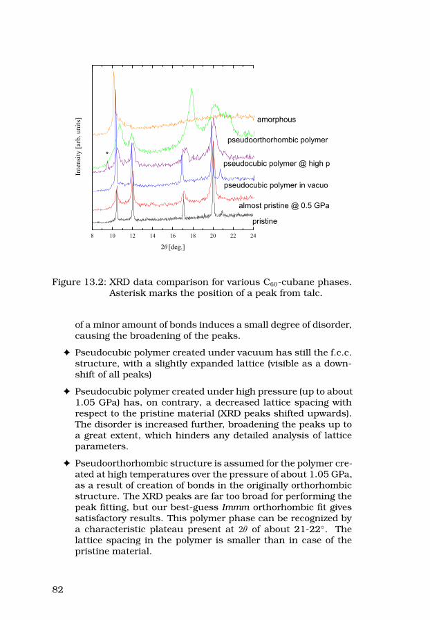
8 10 12 14 16 18 20 22 24
Inte
nsity
[arb
. uni
ts]
[deg.]
amorphous
pseudoorthorhombic polymer
pseudocubic polymer @ high p
pseudocubic polymer in vacuo
pristine
almost pristine @ 0.5 GPa
*
Figure 13.2: XRD data comparison for various C60-cubane phases.Asterisk marks the position of a peak from talc.
of a minor amount of bonds induces a small degree of disorder,causing the broadening of the peaks.
F Pseudocubic polymer created under vacuum has still the f.c.c.structure, with a slightly expanded lattice (visible as a down-shift of all peaks)
F Pseudocubic polymer created under high pressure (up to about1.05 GPa) has, on contrary, a decreased lattice spacing withrespect to the pristine material (XRD peaks shifted upwards).The disorder is increased further, broadening the peaks up toa great extent, which hinders any detailed analysis of latticeparameters.
F Pseudoorthorhombic structure is assumed for the polymer cre-ated at high temperatures over the pressure of about 1.05 GPa,as a result of creation of bonds in the originally orthorhombicstructure. The XRD peaks are far too broad for performing thepeak fitting, but our best-guess Immm orthorhombic fit givessatisfactory results. This polymer phase can be recognized bya characteristic plateau present at 2θ of about 21-22. Thelattice spacing in the polymer is smaller than in case of thepristine material.
82

F Destroyed, amorphous carbon-rich phase has not been di-vided into sub-phases because of the poor quality of XRD datacaused by the huge disorder. The spectrum in the top of fig-ure 13.2 (sample heated to 870 K in vacuum) is showing onlyone peak. If it is assumed to be a left-over (111) peak from thef.c.c. lattice, then the lattice spacing would be comparable tothat of pure C60.
13.1.3 Raman spectra of C60-cubane phases
All the treated samples were analyzed by means of Raman spec-troscopy. The spectra were gathered with Ar+, He-Ne and diodelasers. Ar+ and diode lasers proved to give good results for mostsamples, while He-Ne laser spectra were sometimes dominated byluminescence background and not good enough for Raman analy-sis. Cubane peaks were easily detected by the diode laser, but onlyin the pristine or almost pristine material. It was also possible tosee the cubane peaks with the Ar+ laser (as mentioned in Paper IV),but that required very short exposure times of well below 1 minuteand adding up the intensities from numerous exposures at differentplaces (see figure 13.3).
200 300 400 500 600 700 800 900 1000 1100
Inte
nsity
[arb
. uni
ts]
Raman shift [cm-1]
Figure 13.3: Ar+ spectrum of pristine C60·C8H8 immersed in Vase-line. Vertical lines show the positions of the cubanepeaks.
83

Spectra gathered at higher intensities of the same laser show nosign of cubane and with increasing exposure time the backgroundis considerably rising, which led to a conclusion that 514.5 nmlight might cause a local decomposition of cubane molecules on theirradiated surface.
The overall conclusion from the Raman studies is that the poly-merization does not cause big changes to the Raman spectra ofthe material. It is not possible, as it was in case of C60 polymers,to point out any “fingerprint” feature immediately identifying thestructure. The changes that can be seen are restricted to splittingof Hg modes, minor shifts in peak positions, changes in the rela-tive intensities of the modes and differences in the luminescencebackground visible in the Raman study range.
13.2 C60·C8H8 phase diagram
Based on the results of X-ray diffraction, luminescence and Ramanspectroscopy, a pressure temperature diagram is drawn. It is pos-sible to find (at least, as discussed above) five different structuresof the material: pristine f.c.c. and orthorhombic, pseudocubic andpseudoorthorhombic polymers, and the destroyed, amorphous car-bon phase (see figure 13.4).
The two horizontal solid lines are marking the boundaries for irre-versible changes in the structure of the material. The lower, darkblue line marks the polymerization boundary where covalent bondsbegin to form. The temperature range corresponds to the tempe-rature of cubane decomposition and the interfullerene bonds arecreated using (unknown) cubane breakdown products. It is worthnoting that even though the internal structure is changed, the out-ward appearance of the crystals is not altered (the only differenceis the loss of transparency at polymerization [52]). In contrast toC60, C60·C8H8 polymerization cannot be undone by any treatment,because the cubane molecules are destroyed in the process. Thehigher, black horizontal line marks the destruction of the polymertransforming into of a carbon rich amorphous phase, with a frac-tion of C60 cages still present, but incorporated into a dense networkof broken fullerene cages and cubane skeleton leftovers.
The red, dashed line marks the (reversible) phase boundary be-tween a pristine f.c.c. structure and its orthorhombic counterpartformed at low temperatures and/or at high pressure. The tran-sition is prompted by a decrease of the intermolecular distancesand is related to the orientational ordering transition in C60, how-ever the weak intermolecular interactions in the composite material
84

0.0 0.5 1.0 1.5 2.0100
200
300
400
500
600
700
800
900
Tem
pera
ture
[K]
Pressure [GPa]
pristinef.c.c.
orthorhombic
orthorhombicpolymer
cubic polymer
amorphous carbon
Figure 13.4: Pressure–temperature phase diagram of C60·C8H8. Thesymbols represent the type of structure detected insamples treated at conditions marked by the symbol’sposition. More detailed discussion of the diagram is inthe text.
force the phase boundary to lower temperatures and higher pres-sures. Also, our studies show that the slope of the phase boundarycan be estimated to dT
dp = (295±30) KGPa , almost twice the value for
C60.
The orange vertical line across the polymerization region marks theapproximate boundary between the conditions at which a pseudo-cubic or pseudo-orthorhombic polymer is created. The boundary isplaced at the critical pressure, where the phase transition line cu-bic/orthorhombic is entering the polymerization region. Since, inprinciple, the polymerization process is dependent on time (besidespressure and temperature) the samples treated around this bound-ary show various fractions of each polymeric phase, depending onthe experiment timing.
85

13.3 Comparison between C60 and C60·C8H8
There are numerous similarities, as well as differences, between C60
and a composite with C8H8 as a guest. To start with, both materialsform molecular crystals built of high symmetry elements, van derWaals bonded. The basic crystal structure is face-centered cubic,but an orientational transition is possible in both cases. Moreover,a high-pressure – high-temperature treatment induces changes tothe structure of both materials.
The main differences are summarized in table 13.2.
86

Table 13.2: Differences between C60 and C60-cubane.C60 C60·C8H8
f.c.c. lattice constant at
RT
a = 14.17 Å a = 14.742 Å
molecular recognition no yes
on heating at low
pressure
remains in a pristine state until
reaching the destruction
threshold of C60 molecules;
covalent bonds from previous
polymerization are broken
at about 470 K begins
transforming into a polymer by
breaking up cubane molecules
and creating covalent bonds
between fullerenes via cubane
breakdown products
polymerization
can be reversed under special
treatment; primarily dependent
on the symmetry, structure and
orientation of molecules; direct
interfullerene double bonds
irreversible; primarily dependent
on the lattice structure just
below the polymerization starts;
interfullerene bonds mediated by
hydrocarbons
known polymeric
phases
dimers; orthorhombic (1D, linear
chains); tetragonal (2D);
rhombohedral (2D); ultrahard 3D
polymers. Well defined
structures.
pseudocubic and
pseudoorthorhombic, rather
disordered, with no known
characteristic crystal/bonding
structure
Raman identification
distinct Raman spectra for each
phase, characteristic position of
the Ag(2) mode
small changes in Raman spectra
between different phases
luminescencebroad background, resolved only
at very low temperatures
luminescence background (from
fullerenes) showing distinct
peaks already around 77 K, as
for separated C60 molecules, due
to the very weak intermolecular
interactions.
photopolymerizationpossible; especially with the Ar+
laser at higher intensities
not easy; we suspect that the
Ar+ laser was causing the
breakdown of cubane molecules
at the surface (disappearing
cubane peaks, rising
background) no evidence of
photopolymerization is available
phase transition at zero
pressure
T = 261 K; between f.c.c./simple
cubic
T = 140 K; between
f.c.c./orthorhombic
phase transition slope dTdp = 162
[K
GP a
]dTdp = (295 ± 30)
[K
GP a
]
87
14 C60-nanotubeco-polymerization attempts
I am going to present here the outcome of several experimentswhich I have carried out trying to co-polymerize C60 with carbonnanotubes. These results have not been published yet in any peer-reviewed journal, mainly because I do not consider the study to becompleted. Some partial results were presented on posters at IW-FAC conference in 2003, and NT06 conference in 2006. I was alsohoping to get my samples characterized by high-resolution trans-mission electron microscopy (HR-TEM), but did not yet manage todo so. In any case, I have taken the first steps on the way towardscreating a C60-nanotube co-polymer, and I wanted it to find a placein my thesis. I am rather fond of this concept, and I wish I hadmore time to work on it (and possibly also some co-worker to helpme, especially with the time-consuming characterization stages...).
14.1 Preparation of the mixtures
To my best knowledge, there are no earlier studies of hp-hT treatedC60-nanotube mixtures. Since I was starting from scratch, the firstexperiments were performed on samples with arbitrarily chosencomposition. For the initial experiment I have prepared four typesof samples, to be treated simultaneously: 1) SWNT mixed with C60,prepared by drop-casting of C60 solution in chlorobenzene (C6H5Cl)on pre-compressed nanotube powder, 2) SWNT powder milled ina mortar and pestle with tetragonally polymerized C60 powder, 3)SWNT and 4) pristine C60 powders, for reference. Comparison ofhp-hT treated mixtures was supposed to determine whether co-polymerization is more effective with C60 molecules well spread, likein sample 1) or clustered, as in sample 2). (Tetragonally polymer-ized grains would be depolymerized during the first part of the hp-hT experiment by heating at low pressure and then they would bere-polymerized when the final annealing conditions are reached).
The later experiments were performed on 1:1 mass ratio mixturesof C60 and various carbon nanotube species (SWNT, DWNT, thin
88
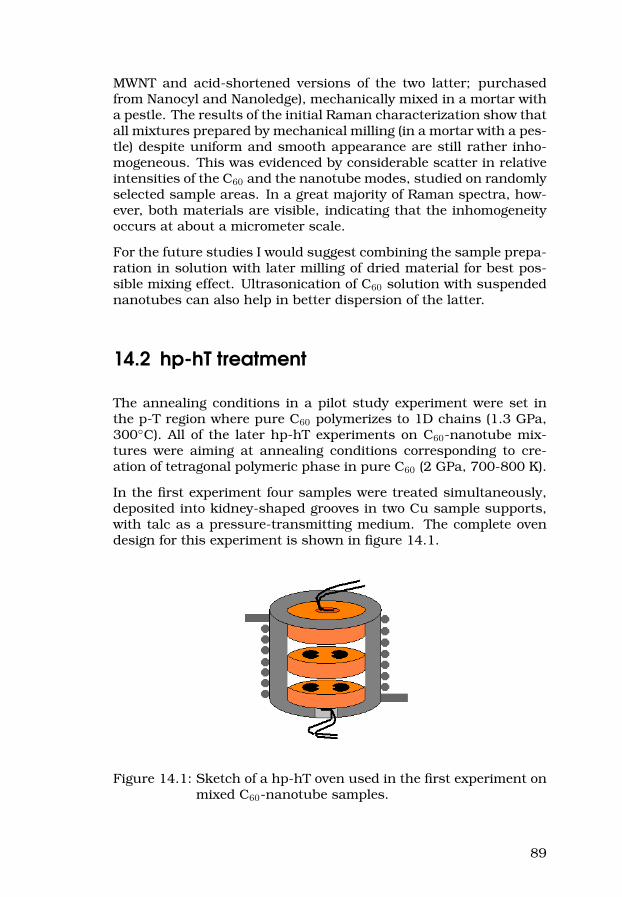
MWNT and acid-shortened versions of the two latter; purchasedfrom Nanocyl and Nanoledge), mechanically mixed in a mortar witha pestle. The results of the initial Raman characterization show thatall mixtures prepared by mechanical milling (in a mortar with a pes-tle) despite uniform and smooth appearance are still rather inho-mogeneous. This was evidenced by considerable scatter in relativeintensities of the C60 and the nanotube modes, studied on randomlyselected sample areas. In a great majority of Raman spectra, how-ever, both materials are visible, indicating that the inhomogeneityoccurs at about a micrometer scale.
For the future studies I would suggest combining the sample prepa-ration in solution with later milling of dried material for best pos-sible mixing effect. Ultrasonication of C60 solution with suspendednanotubes can also help in better dispersion of the latter.
14.2 hp-hT treatment
The annealing conditions in a pilot study experiment were set inthe p-T region where pure C60 polymerizes to 1D chains (1.3 GPa,300C). All of the later hp-hT experiments on C60-nanotube mix-tures were aiming at annealing conditions corresponding to cre-ation of tetragonal polymeric phase in pure C60 (2 GPa, 700-800 K).
In the first experiment four samples were treated simultaneously,deposited into kidney-shaped grooves in two Cu sample supports,with talc as a pressure-transmitting medium. The complete ovendesign for this experiment is shown in figure 14.1.
Figure 14.1: Sketch of a hp-hT oven used in the first experiment onmixed C60-nanotube samples.
89

The C60-SWNT and tetragonal C60-SWNT mixture samples were trea-ted on the bottom Cu plate, the one in direct contact to a type Kthermocouple for more accurate temperature measurements. Thereference, C60-only and SWNT-only samples were treated on themiddle Cu plate.
The oven design shown in fig. 14.1 allowed for treatment of onlysmall sample amounts. The samples spaces needed to be wellmarked, since each pair of materials looks very similar and couldin principle be accidentally switched. Finally, the samples werein a direct contact with the pressure-transmitting medium, whichcaused their intercalation.
14.2.1 Compressible capsules
In the later series of experiments I wanted to eliminate all sourcesof intercalation from around the samples to produce very pure ma-terials. At the expense of a bit less hydrostatic pressure I decidedto give up the direct contact of the samples to the pressure mediumand instead load the C60-nanotube mixtures into extremely thin-walled stainless steel containers. The idea is illustrated in fig-ure 14.2.
(a) Steel capsule design:loading (top), ready forhp-hT (middle), and afterhp-hT (bottom).
(b) Pyrophyllite oven loaded with twostainless steel sample capsules.
Figure 14.2: Final design of a hp-hT oven with thin-walled stainlesssteel sample capsules.
90

The sample powder is contained inside a stainless steel capsule,whose side walls are made as thin as possible. The capsule isclosed by a lid with a wedge for sealing the content. In order tominimize the chances of sample extrusion from below the lid, thelid and inner capsule diameter have to be well matched for a tightfit, which poses a great manufacturing challenge1. Two sample cap-sules fit into a pyrophyllite oven, allowing for simultaneous treat-ment of two different samples under nearly identical conditions (seefig. 14.2 (b)). When the high pressure is applied the thick bottomand lid of a capsule act as mini-pistons and transfer the pressure tothe sample. The thin wall collapses, and thus does not prevent thepressure transmission. Quite opposite, actually, since the capsulewalls are on the outside surrounded by pyrophyllite and thus haveto collapse towards the center.
14.3 Characterization
The characterization method(s) chosen for “co-polymerized” sam-ples had to fulfill a number of requirements. It should be possibleto determine whether covalent bonds were created, and preferably,also define their location and find out if direct fullerene-nanotubeconnections are present. The first requirement is fulfilled by Ra-man spectroscopy, and the results of such a characterization aregoing to be presented in section 14.3.1. The other requirement,however, can only be satisfied by state-of-the-art high resolutionTEM, which I had no access to. Furthermore, I expect that such astudy might prove rather difficult and I shortly address some issuesin section 14.3.2.
14.3.1 Raman spectroscopy
Raman spectroscopy is capable of detecting intermolecular bondsto C60 and even quantify their number, due to the characteristicAg(2) mode softening. It is unfortunately not as useful in testingfor C60-nanotube direct bonding. The results presented below areshowing that C60 polymerizes even when mixed with carbon nano-tubes. It cannot be ruled out, however, that the nanotubes becomelocked in a rather disordered C60 polymer matrix without being co-valently bonded to it.
The Raman spectra on samples already from the first hp-hT experi-ment show the characteristic polymer fingerprints in Ag(2) mode fre-quencies of C60 (see figure 14.3), with the highest intensity around1Luckily, not for Lena, our miracle-making-true workshop technician.
91
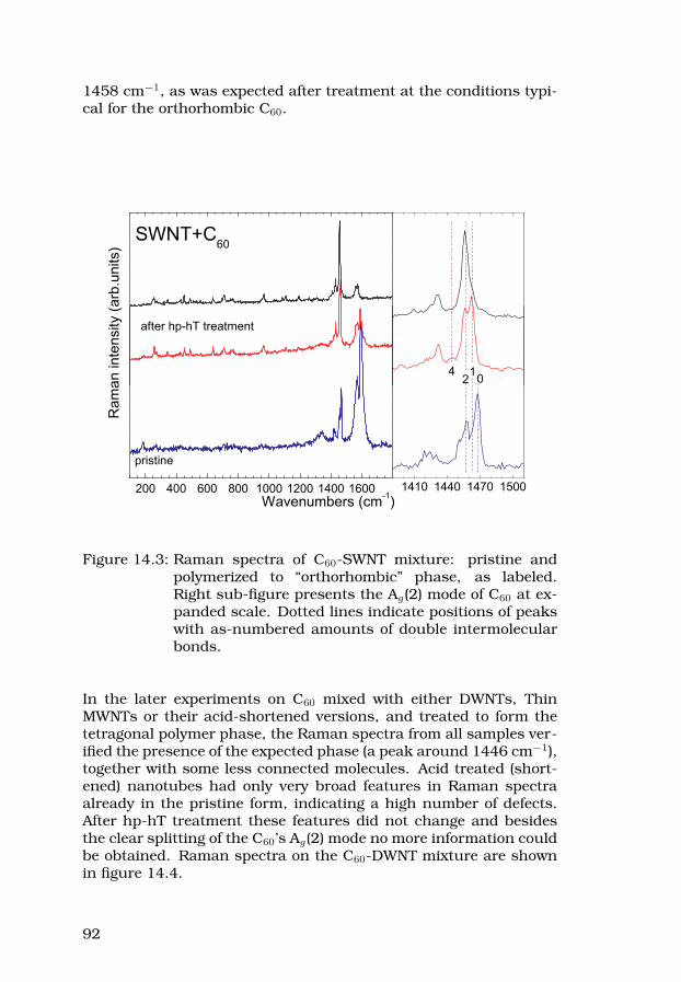
1458 cm−1, as was expected after treatment at the conditions typi-cal for the orthorhombic C60.
after hp-hT treatment
SWNT+C60
200 400 600 800 1000 1200 1400 1600
Ram
an in
tens
ity (a
rb.u
nits
)
Wavenumbers (cm-1)
pristine
4
1410 1440 1470 1500
012
Figure 14.3: Raman spectra of C60-SWNT mixture: pristine andpolymerized to “orthorhombic” phase, as labeled.Right sub-figure presents the Ag(2) mode of C60 at ex-panded scale. Dotted lines indicate positions of peakswith as-numbered amounts of double intermolecularbonds.
In the later experiments on C60 mixed with either DWNTs, ThinMWNTs or their acid-shortened versions, and treated to form thetetragonal polymer phase, the Raman spectra from all samples ver-ified the presence of the expected phase (a peak around 1446 cm−1),together with some less connected molecules. Acid treated (short-ened) nanotubes had only very broad features in Raman spectraalready in the pristine form, indicating a high number of defects.After hp-hT treatment these features did not change and besidesthe clear splitting of the C60’s Ag(2) mode no more information couldbe obtained. Raman spectra on the C60-DWNT mixture are shownin figure 14.4.
92

200 400 600 800 1000 1200 1400 1600
1300 1400 1500 1600
hp-hT treated
pristine
DWCNT+C60
Inte
nsity
[a.u
.]
Raman shift [cm-1]
14
4714
33
146414
5814
69
Figure 14.4: Raman spectra of pristine and “tetragonally” polymer-ized C60-DWNT mixture. The inset shows at an ex-panded scale the Ag(2) mode of C60, with peaks as la-beled, together with the D- and G- bands of DWNT.
14.3.2 Prospects on TEM characterization
The ultimate truth about my samples can only be revealed us-ing high resolution TEM, the only method capable of direct visu-alization of nanostructured materials. The TEM characterizationof hard, bulk samples is, however, not a trivial task. I would ex-pect difficulties with the preparation of polymerized material to bedeposited on a TEM grid, since grinding might introduce many de-fects and be potentially dangerous to covalent bonds (local heating).Also, a C60 molecule attached on a nanotube surface can be “blownaway” by an electron beam during the imaging. Luckily, a recent re-port on C60 grown-into nanotube side walls [88] has demonstratedthat at least the latter problem can be overcome. Despite the diffi-culties, I hope some day to be able to study my “co-polymer” sam-ples by HR-TEM.
93


Part III
Summary of the includedpapers
95

In this part I would like to summarize the content of the papersincluded in this thesis. In each case, I start by explaining the extentof my contribution to the article.
Paper I, II and VI
I have contributed to Paper I and II by AFM characterization of C60
nanorods. For Paper II and VI, I have performed (together with prof.Liu) the hp-hT experiments leading to the polymerization of C60 nano-rods (and single crystals in Paper VI).
These three papers deal with the production and characterizationof C60 nanorods. These highly crystalline, nanosized 1D structurescan be potentially interesting for future, ultimately miniaturizedelectronic circuits or red-range light emitters. Paper I describesa simple production method by crystallization from solution, allow-ing for shape adjustments by small variations in the growth condi-tions. The nanorods can be grown on various substrates (e.g. Si,glass, molybdenum), separated from each other and rectangular incross-section. Nanorods are characterized by AFM, Raman and IRspectroscopies, XRD, SEM, and (HR)TEM combined with FFT analy-sis. As-produced rods have hexagonal, solvated structure, but afterheat treatment at relatively low temperatures (just above 60C) thesolvent is fully removed and nanorods transform to f.c.c. struc-ture (typical for solid C60) with 111 planes on the top and 110 onthe sides. Paper II and VI extend the characterization of nanorodsto optical methods – photoluminescence and Raman spectroscopy.Nanorods can be polymerized by hp-hT treatment and the variouspolymeric phases are found to have distinct PL spectra and typicalRaman fingerprints. A comparative study with hp-hT polymerizedC60 single crystals (Paper VI) reveals however, a number of differ-ences, e.g. Raman lines in nanorod spectra are typically broader.
Paper III, IV and VII
Pristine C60-cubane was synthesized by our collaborators in Hun-gary. In Paper III and IV I have been responsible for hp-hT treat-ment of the samples and partly for their characterization by Ramanspectroscopy and XRD. For Paper VII, I have performed all the photo-luminescence and Raman spectroscopy experiments at low temper-atures. After many discussions of the results with my supervisor,
96
prof. Sundqvist, I have prepared parts (III and IV) or most (VII) of themanuscripts.
The results of hp-hT treatment (III, IV) and characterization of re-cently synthesized C60-cubane compound are presented. The ma-terial is rather unique, due to the exceptionally high symmetryand high compatibility of the two molecular components. We showthat C60-cubane can be irreversibly polymerized under hp-hT con-ditions, and it has a rich p-T phase diagram/reaction map. Thepolymerization mechanism is found to be completely different thanin the case of pure C60. The structure of the polymeric phases isdictated by the lattice structure of the pristine material at the poly-merization threshold temperature rather than molecular symmetryand orientation.
Paper VII complements the earlier studies of C60-cubane compoundby low-temperature optical characterization by photoluminescenceand Raman spectroscopy. We show that the previously reported ori-entational ordering phase transition is visible in PL spectra, whileRaman spectra remain almost unaffected. Weak intermolecular in-teractions in C60-cubane compound, responsible for lowering thetemperature of the rotational ordering transition, also allow formuch better resolution in low-T PL spectra as compared to pristineC60. It seems that C60 molecules surrounded (actually quite tightly)by cubane molecular bearings behave nearly as free molecules, andthe solid state PL spectra of C60·C8H8 at 77 K resemble those of pureC60 in a solution or a gas matrix.
Paper V
C60 and C70 peapods in powder form were provided by our collabo-rators. I have participated in production of oriented peapod films, aswell as in the preparations and carrying out of the hp-hT treatment.I have tried to characterize the samples by Raman spectroscopy, butthe results were not included in the paper, since no fullerene modescould be detected. I have been also involved in manuscript editing.
This paper presents the results of a detailed study of high-pressuretreated C60 and C70 peapods. It is shown that fullerenes restrictedwithin carbon nanotubes react to high pressure in a different waythan their free counterparts. Based on p-T diagrams of both C60
and C70 one expects that these molecules should form well-definedpolymeric structures when annealed at certain, well known highpressure and high temperature conditions. In a carbon nanotubepeapod, however, fullerenes are forming chains, and are thus stackeddifferently than in their “natural” 3D crystal lattices. Hp-hT fullerene
97
polymerization requires certain mutual molecular orientations, whichare not always possible inside of a peapod. We show that the spheri-cal C60, which can rotate and re-orient even inside of a peapod, canbe polymerized at p-T conditions consistent with those of C60 inbulk form. Larger and elongated C70 molecules, however, remainunpolymerized inside peapods under pressure up to 2.5 GPa and300C. XRD characterization provides a neat explanation of thisbehavior by showing that both observed stacking patterns of C70
inside of carbon nanotubes are incompatible with the molecules’orientation in a polymeric chain. Theoretically, C70 chains could befitted inside of carbon nanotubes, but the available space filling isthen less optimal, and thus unlikely.
Paper VIII
In this work I have been responsible for preparing and carrying outthe in situ resistance measurements under high pressure, includingdesigning parts of the pressure cell, assembling the cells, writing aLabView program for data logging and running the experiments. Ihave also done most of the analysis of the resistance data includingthe fitting. Finally, I have taken part in the discussions and preparedthe first version of the manuscript.
The results of direct resistance measurements on Rb4C60 in situ,under high pressure are presented. The study was prompted bya poor understanding of the semiconducting behaviour of alkalimetal (A) intercalation compounds with A4C60 stoichiometry. Arecent NMR study suggested that an insulator-to-metal transitionmay occur in Rb4C60 under high pressures below 1.2 GPa, and weintended to prove it by a direct electric measurement. Unfortu-nately, our study shows that there is no such insulator-to-metaltransition, and this is the main message of Paper VIII. Rb4C60 ex-hibits a stable semiconducting behaviour at pressures between 0and 2 GPa and in the temperature range of 90 to about 420 K.The conduction of Rb4C60 in the studied temperature range is dom-inated by self-doping behaviour, caused by gap states (attributedto defects) forming at about 0.1 eV from the conduction band. Athigher temperatures we observe a kick-in of a second activated be-haviour, with energy gap parameter of about 0.7 eV, which is inexcellent agreement with the previously reported “intrinsic”, opticalgap of Rb4C60. To obtain good fits to our data also at the lowesttemperatures we have complemented the conduction model by ametallic term, since small amounts of Rb3C60 were known to bepresent in the samples. Finally, we observed metallization in some
98

of our samples on heating above 460 K, but we were able to showthat it was caused by a rapid loss of Rb from the samples which inconsequence transformed to metallic Rb3C60. The data presentedin Paper VIII is in principle compatible with the existence of aninsulator-to-metal transition in Rb4C60 at very high pressures, butsince no studies above 5.2 GPa were reported, an extended studyin necessary.
Paper IX
Crystal growth experiments were carried out by prof. Sundqvist andme. I have also carried out the hp-hT treatment of C60 single crystals(aiming at the tetragonal polymer phase), and then characterized thesamples by Raman spectroscopy. Finally, I have prepared most ofthe manuscript after discussing the results with the co-authors.
The latest paper addresses the qualitative differences in Ramanspectra collected on various fragments of nominally identical sam-ples – tetragonally polymerized C60 single crystals. The analysis isbased on a statistically significant number of spectra and showsthat the “worse quality” of some Raman data can be physicallyexplained. We attribute the broadening of Raman peaks to inter-nal strains which are present in a polymerized single crystal afterhigh pressure is released. The single crystals are compared to C60
nanorods and powder samples. Our data shows that Raman spec-troscopy can be used for assessment of strain gradients in polymer-ized molecular systems.
99


Part IV
Supplementary material
101

15 Overview of activities notincluded in this thesis
As I have already explained in the introduction, during my graduatestudies I have been working with many different projects. I haveattended several international summer schools and conferences,often presenting there some of my results. In this chapter I wouldlike to give an overview of those of my scientific activities up to date,which were not directly included in this thesis.
15.1 List of publications
15.1.1 In peer reviewed journals
1. “A study of surface modification and anchoring techniques usedin the preparation of monolithic microcolumns in fused silicacapillaries”Julien Courtois, Michal Szumski, Emil Byström, Agnieszka Iwasiewicz,Andrei Shchukarev, Knut IrgumJournal of Separation Science 29 (2006) 14-24http://dx.doi.org/10.1002/jssc.200500294
2. “Light emission at 5 V from a polymer device with a millimeter-sized interelectrode gap”Joon-Ho Shin, Andrzej Dzwilewski, Agnieszka Iwasiewicz, Steven Xiao,Åke Fransson, Genesis Ngwa Ankah and Ludvig EdmanApplied Physics Letters 89 (2006) 013509http://dx.doi.org/10.1063/1.2219122
3. “Variable force Tapping Atomic Force Microscopy as a tool in thecharacterization of organic devices”Agnieszka Iwasiewicz, Joon-Ho Shin, Steven Xiao and Ludvig EdmanUltramicroscopy 107 (2007) 1078-1085http://dx.doi.org/10.1016/j.ultramic.2007.02.044
103
15.1.2 In conference proceedings
1. “Synthesis and high pressure induced polymerization of C60
nanorod”B.B. Liu, L. Wang, Y.Y. Hou, M.G. Yao, G. Zou, A. Iwasiewicz and B.SundqvistProc. 2nd Asian Conf. on High Pressure Res. (ACHPR-2), Nara2004, achpr-0446.pdf; M. Yoshida and S. Kubota, editors; Res.Center for Explosion Safety, Natl. Inst. of Adv. Ind. Sci. & Technol.(AIST), Ibaraki, Japan; ISBN 4-9902441-0-9.
2. “High-pressure induced polymerization of C60 nanorods”B.B. Liu, L. Wang, Y.Y. Hou, M.G. Yao, G.T. Zou, A. Iwasiewicz andB. SundqvistProc. Joint 20th AIRAPT and 43rd EHPRG Conf. on High Pres-sure Science and Technology, Karlsruhe 2005, Nanomat-O133;E. Dinjus and N. Dahmen, editors; Forschungszentrum Karlsruhe2005, ISBN 3-923704-49-6; available free at:www.unipress.waw.pl/airapt/AIRAPT-20/html/proceedings/index.html
3. “High-Pressure Studies of the Rotor-Stator Compound C60-Cu-bane”A. Iwasiewicz-Wabnig, B. Sundqvist, É. Kováts and S. PekkerMaterials Research at High Pressure (Proc. Symp. PP of the2006 MRS Fall Meeting, Boston, MA 2006; Mater. Res. Soc.Symp. Proc. 987E; A. Goncharov, R. Bini, M. Riad Manaa, and R.J.Hemley, editors; MRS, Warrendale, PA, 2007) paper 0987-PP03-04.
4. “High pressure and high temperature induced polymeric C60
nanorods and their photoluminiscence properties”B.B. Liu, Y.Y. Hou, L. Wang, G.T. Zou, A. Iwasiewicz and B. SundqvistMaterials Research at High Pressure (Proc. Symp. PP of the2006 MRS Fall Meeting, Boston, MA 2006; Mater. Res. Soc.Symp. Proc. 987E; A. Goncharov, R. Bini, M. Riad Manaa, and R.J.Hemley, editors; MRS, Warrendale, PA, 2007) paper 0987-PP03-08.
15.2 Conferences
ISIC 12 International Symposium on Intercalation Compounds, 1-5June 2003, Poznan, Poland (attended, no contribution)
IWFAC’2003 International Workshop Fullerenes and Atomic Clusters,30 June – 4 July 2003, St. Petersburg, Russia
F Poster P256: Fullerene - nanotube composites. A. Iwasiewicz,B. Sundqvist
F Poster P119: From tetragonal C60 to graphitized fullerene. A.Dzwilewski, A. Iwasiewicz, T. L. Makarova, B. Sundqvist.
104

Veeco Instruments Scanning Probe Microscopy Applications Confer-ence & Users Meeting 10-11 March 2004, Copenhagen, Denmark
F Poster: AFM investigation of the morphological structure of tetrag-onal C60 polymers. Agnieszka Iwasiewicz, Bingbing Liu
SPM 2004 – The Fifth Nordic-Baltic SPM Workshop, 16-19 June 2004,Trondheim, Norway
F Oral presentation: A comparative AFM study of single crystalC60 in the pristine and the tetragonal polymer states. AgnieszkaIwasiewicz and Bertil Sundqvist
NT05 – 6th International Conference on the Science and Applicationof Nanotubes, 26 June – 1 July 2005, Göteborg, Sweden (attendedas a part of a VT2005 individual SJCKMS research project stipend,no contribution)
Montpellier 2006 Scanning Probe Microscopy Sensors and Nanos-tructures, 3-6 June 2006, Montpellier, France
F Oral presentation: Variable force Tapping AFM phase imagingas a tool in the characterization of organic devices. AgnieszkaIwasiewicz, Joon-Ho Shin, Steven Xiao, Ludvig Edman
F Poster N5: Contact AFM studies of tetragonal C60 polymers –surprising experimental results and a simple theoretical model.Agnieszka Iwasiewicz , Joachim Wabnig, Thomas Wågberg,Bertil Sundqvist
NT06 – 7th International Conference on Science and Application ofNanotubes, 18-23 June 2006, Nagano, Japan
F Poster E.008: C60-carbon nanotube composites – a search forultrahard, light materials. Agnieszka Iwasiewicz, Shidan Yu,Yonggang Zou, Bingbing Liu and Bertil Sundqvist
2nd Workshop of Nordic Network for Women in Physics, 29-30 Novem-ber 2006, Lund, Sweden (presenting the poster from NT06 Confer-ence)
105

2006 MRS (Materials Research Society) Fall Meeting, 27 November –1 December 2006, Boston, MA, USA (not attended in person)
F Poster PP3.4: High-Pressure Studies of the Rotor-Stator Com-pound Cubane-C60. Bertil Sundqvist, Agnieszka Iwasiewicz,Eva Kovats, Sandor Pekker and Istvan Jalsovszky
F Poster PP3.8: High Pressure and High Temperature InducedPolymeric C60 Nanorods and Their Photoluminescence Proper-ties. Bingbing Liu, Yuanyuan Hou, Lin Wang, Guangtian Zou,Agnieszka Iwasiewicz and Bertil Sundqvist
F Poster Q5.40: A Facile Solution Method to Synthesis of C60
Nanorods. Bingbing Liu, Lin Wang, Guangtian Zou, AgnieszkaIwasiewicz and Bertil Sundqvist
Aminoff Symposium: “Carbon Nanotubes – With an eye on the nano-world”, Royal Academy of Sciences (KVA), 13-14 June 2007, Stock-holm, Sweden
14th International Conference of Intercalation Compounds (ISIC-14),Seoul, Korea, June 2007 (not attended in person)
F Poster : The electrical resistance of Rb4C60 under pressure. A.Iwasiewicz-Wabnig, T. Wågberg, and B. Sundqvist
International Conference on Nano Science and Technology (ICN&T2007), Stockholm 2007 (not attended in person)
F Poster: Low-temperature optical studies of C60-cubane rotor-stator compound. A. Iwasiewicz-Wabnig, É. Kováts, S. Pekker,and B. Sundqvist
Quantum Information Processing Interdisciplinary Research Collab-oration (QIP IRC) Conference, 25-26 June 2007, St. Anne’s College,Oxford, UK
106

15.3 Summer schools and other
Practical Aspects of Magnets, Cryogenics, Thermometry and Vac-uum, 25-27 November 2002, Oxford, UK (a training course orga-nized by Oxford Instruments and University of Oxford)
4th International Wilhelm & Else Heraeus Summer School: Funda-mentals of Quantum Information processing, 20 July – 2 August 2003,Lutherstadt Wittenberg, Germany (attended, no contribution)
54th Meeting of Nobel Prize Winners in Lindau, Germany, 27 June –2 July 2004 (an international meeting of Nobel Prize winners withstudents, attended thanks to a stipend from the Nobel Foundation)
ESONN’2004 European School on Nanosciences & Nanotechnolo-gies, 22 August – 10 September 2004, Grenoble, France (attendedas a part of a VT2004 individual SJCKMS research project stipend)
F Poster: Investigation of C60 polymers Agnieszka Iwasiewicz
Tutorial day preceding the NT05 conference, 26 June 2005, Göte-borg, Sweden Including sessions: “Raman scattering in carbonnanotubes” by Mildred S. Dresselhaus (MIT) and “Tutorial on elec-tronic transport” by Jesper Nygård (Niels Bohr Institute, Copen-hagen)
Tutorial day preceding the NT06 conference, 18 June 2006, Nagano,Japan Including sessions: “Introduction and theoretical background”David Tománek (Michigan State University); “Physical propertiesand characterization” by Mildred S. Dresselhaus (MIT); “Synthe-sis techniques” by Esko I. Kauppinen (Helsinki University of Tech-nology); “Chemical modification and applications of nanotubes” byMauricio Terrones (IPICYT Mexico); “Electrical and thermal trans-port” by John E. Fischer (University of Pennsylvania).
QIP IRC Workshop, 27-29 June 2007, St. Anne’s College, Oxford, UK
107

Final remarks
I find carbon nanostructures extraordinary, in many aspects. Maybemy thesis convinced you, as well, that there is something to all thisfuzz. There certainly are possibilities on the horizon, but just asmany unsolved problems still stand in our way. The nanostructuresare beautiful, but understanding the physics behind their proper-ties is not straightforward. We have learned so much about themalready, that I believe no person can claim to know everything so fardiscovered about these fascinating materials. My sincere hope forthe future is that the scientific community will bear the weight ofsuch a broad and still expanding field, tying the loose ends togetheruntil most of the options are exploited. I hope people will not giveup the search, and especially that the field will not be quenched byeither political impatience or economic infeasibility. It would be ashame to waste such an unimaginable amount of knowledge. I amglad that also I could make my small contribution.
108

Acknowledgments
I consider the years spent in Umeå among of the best times of mylife, entirely due to the great people whom I met during my graduatestudies here. Obviously, that has a lot to do with the fact that youare right now holding my PhD thesis in your hand. I want to thankhere all those people whom I have worked with or had good timetogether (and in many cases these things are inseparable).
First of all, I would like to mention PROFESSOR BERTIL SUNDQVIST,my supervisor, who is in my opinion as near to an ideal experi-mentalist as one can ever get. His great ideas, highly contageousscientific curiosity, enormous knowledge and unimaginable intu-ition were always a great inspiration for me. I would like to thankBertil especially for always being so enthusiastic.
Thanks to TATIANA MAKAROVA, my second supervisor, THOMAS WÅG-BERG, LUDVIG EDMAN, OVE ANDERSSON and OVE AXNER who werealways ready to help me with their advice. Special thanks for PRO-FESSOR BINGBING LIU. It was pleasure to work together!
Big thanks to the workshop staff: LENA ÅSTRÖM, MARTIN FÖRS-GREN and TOMAS GUSTAFSSON, whose work made my experimentspossible. It is hard to believe what miracles Lena performs in theworkshop, almost nothing is impossible for her.
PATRIK STENMARK, PIOTR MATYBA and JÖRGEN ERIKSSON were re-sponsible for keeping up the good mood, and much more than that.Sharing the room with Patrik and Piotr was really enjoyable. Thatapplies also to my earlier room-mates.
During lunch breaks and on some other spare-time occasions manyinteresting discussions took place (about science and/or politicsand/or completely abstract problems). Together with those alreadymentioned above: ANDREI, ANDERS, HANS, MICHAEL, EMIL, MAT -TIAS, LEIF, and LARS-ERIK are to be especially blamed.
Finally, at our department we have the most extraordinary admin-istrators, finding remedies to every possible bureaucratic problemand always being so very kind. “Årets ros” for MARGARETHA, ANN-CHARLOTT and LILIAN.
I would like to thank all the other people at the Department ofPhysics in Umeå, for creating such a great atmosphere at work.
109

To complete the “professional” acknowledgments, I need to mentionthe people who had their part in my choice of carrier as a physicist,by sharing their passion of physics with me. Special thanks forthat to Mrs. Kempinska and Mrs. Moldenhawer, Dr. Kotłowska,Dr. Skupinski, Dr. Wójcik, Prof. Parzynski and the fellow physicsstudents in Poznan.
There is much more to life than just work. There is love and friend-ship, without which it would all be pointless. The gratitude forbringing meaning to my life is best expressed without words, andI find no way to describe it. Nevertheless, I want to mention thosewho were always there for me.
First of all, JOACHIM, my dearest husband and best friend. And myFAMILY, for their love and constant support despite the distance.
KAROLINA, ASIA, ALEKSANDRA, MAGDA, ANIA with Family, FLO-RIAN and JUNKO, STEFAN, ROBERT and EMMA, PIOTR and ANNA,CLAUDE and CAROLINE, MACIEJ, PAWEŁ, JULIE, JOHN, CONNIE,SUN-KYOUNG, PRINCE, THE JOHANSSONS FAMILY, THE FLEMMINGS,FR. JOSE and FR. BINU. For being my friends all this time.
LARS-GUNNAR MARTLING with CAMERATA UMENSIS, and ANIA WINEK
ALBERTSSON with CHORALL, for friendship and all the music.
And last, but not least – I would like to thank all those whom Iam grateful to, despite the fact that I forgot to mention their nameshere.
110

Bibliography
[1] Agnieszka Iwasiewicz-Wabnig “Polymerization of the rotor-statorcompound C60-cubane under high pressure”, Licentiate Thesis,Department of Physics, Umeå University, December 2006.
[2] Neil W. Ashcroft, N. David Mermin, “Solid State Physics”, Har-court College Publishers (1976)
[3] M.S. Dresselhaus, G. Dresselhaus, P.C. Eklund, “Science ofFullerenes and Carbon Nanotubes”, Academic Press (1996)
[4] H. Kuzmany, “Solid state spectroscopy. An introduction”,Springer (1998)
[5] Peter W. Stephens (editor), “Physics & Chemistry of Fullerenes.A Reprint Collection”, World Scientific Publishing (1993)
[6] Thomas Wågberg “Studies of polymeric and intercalated phasesof C60”, PhD Thesis, Department of Experimental Physics,Umeå University (2001)
[7] J. Dryzek, E. Dryzek and P. Golonka, J. Phys.: Condens. Matter14 (2002) 13857-13866
[8] B. Sundqvist, Rev. Sci. Instrum. 69 (1998) 3433
[9] http://lsu.epfl.ch/cours/ultra/Bas-XRD.pdf
[10] H.W. Kroto, J.R. Heath, S.C. O’Brien, R.F. Curl & R.E. Smalley,Nature 318 (1985) 162-163
[11] http://www.kroto.info/
[12] H.W. Kroto, Nature 329 (1987) 529
[13] T.G. Schmalz, W.A. Seitz, D.J. Klein, G.E. Hite, J. Am. Chem.Soc. 110 (1988) 1113
[14] Point Group Symmetry web page, Univ. of Newcastle upon Tynehttp://www.phys.ncl.ac.uk/staff/njpg/symmetry/index.html
[15] W. Krätschmer, L.D. Lamb, K. Fostiropoulos, and D.R. Huff-man, Nature 347 (1990) 354-358
[16] A. Lundin, B. Sundqvist, Phys. Rev. B 53 (1996) 8329
[17] G.A. Samara, L.V. Hansen, R.A. Assink, B. Morosin, J.E.Schirber, D. Loy, Phys. Rev. B 47 (1993) 4756
[18] B. Sundqvist, Adv. Phys. 48 (1999) 1-134
111

[19] B. Sundqvist, Structure and Bonding 109 (2004) 85-126
[20] A.M. Rao, P.C. Eklund, U.D. Venkateswaran, J.Tucker, M.A.Duncan, G.M. Bendele, P.W. Stephens, J.-L. Hodeau, L. Mar-ques, M. Núñez-Regueiro, O.I. Bashkin, E.G. Ponyatovsky, A.P.Morovsky, Appl. Phys. A 64 (1997) 231-239
[21] A.M. Rao, P. Zhou, K.-A. Wang, G.T. Hager, J.M. Holden, Y.Wang, W.-T. Lee, X.-X. Bi, P.C. Eklund, D.S. Cornett, M.A.Duncan, I.J. Amster, Science 259 (1993) 955
[22] T. Wågberg, P. Jacobsson, B. Sundqvist, Phys. Rev. B, 60(1999) 4535-4538
[23] É. Kováts, G. Oszlányi and S. Pekker, J. Phys. Chem. B 109(2005) 11913-11917
[24] J.E. Fischer, P.A. Heiney, D.E. Luzzi, and D.E. Cox, ACSsymposium series 481 “Fullerenes. Synthesis, Properties, andChemistry of Large Carbon Clusters” edited by George S. Ham-mond and Valerie J. Kuck, Chapter 4, page 55 (1992) AmericanChemical Society Washington DC
[25] O. Zhou, J.E. Fischer, N.Coustel, S. Kycia, Q. Zhu, A.R.McGhie, W.J. Romanow, J.P. McCauley Jr, A.B. Smith III andD.E. Cox, Nature 351 (1991) 462 - 464
[26] D.W. Murphy, M.J. Rosseinsky, R.M. Fleming, R. Tycko, A.P.Ramirez, R.C. Haddon, T. Siegrist, G. Dabbagh, J.C. Tully andR.E. Walstedt, J. Phys. Chem. Solids 53 (1992) 1321-1332
[27] R.C. Haddon, A.F. Hebard, M.J. Rosseinsky, D.W. Murphy,S.J. Duclos, K.B. Lyons, B.Miller, J.M. Rosamilia, R.M. Flem-ing, A.R. Kortan, S.H. Glarum, A.V. Makhija, A.J. Muller, R.H.Eick, S.M. Zahurak, R. Tycko, G. Dabbagh and F.A. Thiel, Na-ture 350 (1991) 320 - 322
[28] S.J. Duclos, R.C. Haddon, G. Glarum, A.F. Hebard, K.B.Lyons, Science 254 (1991) 1625-1627
[29] P.W. Stephens, G. Bortel, G. Faigel, M. Tegze, A. Jánossy, S.Pekker, G. Oszlanyi, L. Forró, Nature 370 (1994) 636-639
[30] G.M. Bendele, P.W. Stephens, K. Prassides, K. Vavekis, K. Ko-rdatos, and Katsumi Tanigaki, Phys. Rev. Lett. 80 (1998) 736-739
[31] G. Oszlányi, G. Baumgartner, G. Faigel and L. Forró, Phys.Rev. Lett. 78 (1997) 4438-4441
[32] G. Oszlányi, G. Bortel, G. Faigel, L. Gránásy, G.M. Bendele,P.W. Stephens, L. Forró, Phys. Rev. B 54 (1996) 11849-11852
[33] A. F. Hebard, M. J. Rosseinsky, R. C. Haddon, D. W. Murphy,S. H. Glarum, T. T. M. Palstra, A. P. Ramirez and A. R. Kortan,Nature 350 (1991) 600 - 601
112
[34] K. Holczer, O. Klein, S.M. Huang, R.B. Kaner, K.J. Fu, R.L.Whetten, F. Diederich, Science 252 (1991) 1154-1157
[35] M.J. Rosseinsky, A.P. Ramirez, S.H. Glarum, D.W. Murphy,R.C. Haddon, A.F. Hebard, T.T.M. Palstra, A.R. Kortan, S.M.Zahurak, and A.V. Makhija, Phys. Rev. Lett. 66 (1991) 2830 -2832
[36] K. Tanigaki, T. W. Ebbesen, S. Saito, J. Mizuki, J. S. Tsai, Y.Kubo and S. Kuroshima, Nature 352 (1991) 222 - 223
[37] P.E. Eaton and T.W. Cole, J. Am. Chem. Soc. 86 (1964) 3157-3158
[38] D.H.R. Barton, D. Crich, W.B. Motherwell, J. Chem. Soc.Chem.Commun. (1983) 939-941
[39] J.C. Barborak, L.Watts, R. Pettit, J. Am. Chem. Soc. 88 (1966)1328
[40] P.E. Eaton, Angew. Chem. Int. Ed. Engl. 31 (1992) 1421-1436
[41] K.D. Kybett, S. Carroll, P. Natalis, D.W. Bonnell, J.L. Margrave,J.L. Franklin, J. Am. Chem. Soc. 88 (1996) 626
[42] Cubane web page, School of Chemistry, University of Bristol,www.chemsoc.org/ExemplarChem/entries/2004/bristol_hook/home/
[43] E.B. Fleischer, J. Am. Chem. Soc. 86 (1964) 3889
[44] T. Yildirim, P.M. Gehring, D.A. Neumann, P.E. Eaton, T. Em-rick, Phys. Rev. Lett. 78 (1997) 4938-4941
[45] T.W. Cole Jr., J. Perkins, S. Putnam, P.W. Pakes, H.L. Strauss,J. Phys. Chem. 85 (1981) 2185-2189
[46] E.W. Della, E.F. McCoy, H.K. Patney, G.L. Jones, F.A. Miller, J.Am. Chem. Soc. 101 (1979) 7441
[47] B.S. Jursic, J. Mol. Struct. (TEOCHEM) 394 (1997) 15-18
[48] G. Ramachandran, S. Manogaran, J. Mol. Struct. (TEOCHEM)719 (2005) 7-16
[49] C.P. Vlahacos, H.F. Hameka, J.O. Jensen, Chem. Phys. Lett.259 (1996) 283-286
[50] G.J. Piermarini, S. Block, R. Damavarapu, S. Iyer, Propellants,Explosives, Pyrotechnics 16 (1991) 188-193
[51] D.R. Kirklin, K.L. Churney, E.S. Domalski, J. Chem. Thermo-dyn. 21 (1989) 1105-1113
[52] S. Pekker, É. Kováts, G. Oszlányi, G. Klupp, G. Bortel, I.Jalsovszky, E. Jakab, F. Borondics, K. Kamarás, M. Bokor, G.Kriza, K. Tompa, G. Faigel, Nature Materials 4 (2005) 764-767
113
[53] S. Pekker, É. Kováts, G. Oszlányi, Gy. Bényei, G. Klupp, G.Bortel, I. Jalsovszky, E. Jakab, F. Borondics, K. Kamarás andG. Faigel, phys. stat. sol. (b) 243 (2006) 3032-3036
[54] ”Carbon Nanotubes. Preparation and Properties.”, edited byThomas W. Ebbesen, CRC Press, Inc. (1997)
[55] R. Saito, G. Dresselhaus, M.S. Dresselhaus “Physical Proper-ties of Carbon Nanotubes”, Imperial College Press (first pub-lished 1998)
[56] S. Reich, C. Thomsen, J. Maultzsch “Carbon Nanotubes. BasicConcepts and Physical Properties.”, Wiley-VCH (2004)
[57] S.V. Rotkin, S. Subramoney (Eds.) “Applied Physics of CarbonNanotubes. Fundamentals of Theory, Optics and Transport De-vices.”, Springer, Berlin Heidelberg (2005)
[58] A. Loiseau, P. Launois, P. Petit, S. Roche, J.-P. Salvetat (Eds.)“Understanding Carbon Nanotubes. From Basics to Applica-tions.”, Springer, Berlin Heidelberg (2006)
[59] S. Iijima, Nature 354 (1991) 56-58
[60] S. Iijima and T. Ichihashi, Nature 363 (1993) 603-605
[61] D.S. Bethune, C.H. Klang, M.S. de Vries, G. Gorman, R. Savoy,J. Vazquez, R. Beyers, Nature 363 (1993) 605 - 607
[62] This figure was prepared based on the atom positions cal-culated using the “nanotube coordinate generator” programavailable at Dr. Maruyama’s web page:www.photon.t.u-tokyo.ac.jp/~maruyama/wrapping3/wrapping.html
I am very grateful to prof. Shigeo Maruyama for making thisvery useful software available online, free of charge.
[63] S. Iijima, T. Ichihashi and Y. Ando, Nature 356 (1992) 776-778
[64] A. Krishnan, E. Dujardin, T.W. Ebbesen, P.N. Yianilos andM.M.J. Treacy, Phys. Rev. B 58 (1998) 14013-14019
[65] B.I. Yakobson, C.J. Brabec and J. Bernholc, Phys. Rev. Lett.76 (1996) 2511-2514
[66] D.A. Walters, L.M. Ericson, M.J. Casavant, J. Liu, D.T. Colbert,K.A. Smith and R.E. Smalley, Appl. Phys. Lett. 74 (1999) 3803-3805
[67] M.-F. Yu, B.S. Files, S. Arepalli and R.S. Ruoff, Phys. Rev. Lett.84 (2000) 5552-5555
[68] Q. Zhao, M. Buongiorno Nardelli and J. Bernholc, Phys. Rev.B 65 (2002) 144105
[69] J.Y. Huang, S. Chen, Z.Q. Wang, K. Kempa, Y.M. Wang, S.H.Jo, G. Chen, M.S. Dresselhaus, Z.F. Ren, Nature 439 (2006)281
114

[70] M.-F. Yu, O. Lourie, M.J. Dyer, K. Moloni, T.F. Kelly, R.S. Ruoff,Science 287 (2000) 637-640
[71] J.N. Coleman, U. Khan, W.J. Blau, Y.K. Gun’ko, Carbon 44(2006) 1624-1652
[72] B. Vigolo, A. Pénicaud, C. Coulon, C. Sauder, R. Pailler, C.Journet, P. Bernier, P. Poulin, Science 290 (2000) 1331-1334
[73] A.B. Dalton, S. Collins, E. Muñoz, J.M. Razal, V.H. Ebron, J.P.Ferraris, J.N. Coleman, B.G. Kim, R.H. Baughman, Nature 423(2003) 703
[74] K. Jiang, Q. Li, S. Fan, Nature 419 (2002) 801
[75] Y.-L. Li, I.A. Kinloch, A.H. Windle, Science 304 (2004) 276-278
[76] M. Zhang, K.R. Atkinson, R.H. Baughman, Science 306 (2004)1358-1361
[77] M. Zhang, S. Fang, A.A. Zakhidov, S.B. Lee, A.E. Aliev, C.D.Williams, K.R. Atkinson, R.H. Baughman, Science 309 (2005)1215-1219
[78] American Scientist magazine, July –August 1997
[79] N.M. Pugno, J. Phys.: Condens. Matter 18 (2006) S1971-S1990
[80] R. Saito, G. Dresselhaus, M.S. Dresselhaus, Phys. Rev. B 61(2000) 2981-2990
[81] This figure was prepared based on the data available at Dr.Maruyama’s web page:http://reizei.t.u-tokyo.ac.jp/~maruyama/kataura/kataura.html
[82] A. Maiti, Nature Materials 2 (2003) 440-442
[83] S.-L. Zhang, X. Hu, H. Li, Z. Shi, K.T. Yue, J. Zi, Z. Gu, X. Wu,Z. Lian, Y. Zhan, F. Huang, L. Zhou, Y. Zhang and S. Iijima,Phys. Rev. B 66 (2002) 035413
[84] H. Kataura, Y. Kumazawa, Y. Maniwa, I. Umezu, S. Suzuki,Y. Ohtsuka and Y. Achiba, Synthetic Metals 103 (1999) 2555-2558
[85] B.W. Smith, M. Monthioux and D.E. Luzzi, Nature 396 (1998)323-324
[86] C.-K. Wu and M. Nicol, Chem. Phys. Lett. 21 (1973) 153-157
[87] N. Bendiab, R. Almairac, J.-L. Sauvajol, S. Rols and E. Elkaim,J. Appl. Phys. 93 (2003) 1769
[88] A.G. Nasibulin, P.V. Pikhitsa, H. Jiang, D.P. Brown, A.V.Krashennikov, A.S. Anisimov, P. Queipo, A. Moisala, D. Gon-zalez, G. Lientschnig, A. Hassanien, S.D. Shandakov, G. Lolli,D.E. Resasco, M. Choi, D. Tománek and E.I. Kauppinen, Na-ture Nanotechnology 2 (2007) 156-161
115