structural robustness and timber buildings – a review1190181/...structural robustness and timber...
TRANSCRIPT
Full Terms & Conditions of access and use can be found athttp://www.tandfonline.com/action/journalInformation?journalCode=swoo20
Wood Material Science & Engineering
ISSN: 1748-0272 (Print) 1748-0280 (Online) Journal homepage: http://www.tandfonline.com/loi/swoo20
Structural robustness and timber buildings – areview
Johannes A. J. Huber, Mats Ekevad, Ulf Arne Girhammar & Sven Berg
To cite this article: Johannes A. J. Huber, Mats Ekevad, Ulf Arne Girhammar & Sven Berg (2018):Structural robustness and timber buildings – a review, Wood Material Science & Engineering, DOI:10.1080/17480272.2018.1446052
To link to this article: https://doi.org/10.1080/17480272.2018.1446052
Published online: 13 Mar 2018.
Submit your article to this journal
View related articles
View Crossmark data
Structural robustness and timber buildings – a reviewJohannes A. J. Huber , Mats Ekevad , Ulf Arne Girhammar and Sven Berg
Division of Wood Science and Engineering, Department of Engineering Sciences and Mathematics, Luleå University of Technology, Skellefteå,Sweden
ABSTRACTTimber buildings are increasing in their dimensions. Structural robustness is imperative for allbuildings and specifically important for tall buildings. Lives can be saved if disproportionatecollapse can be avoided after a catastrophic event (e.g. accident, terrorism). The literature aboutrobustness is comprehensive concerning concrete and steel buildings, but is rather limitedregarding timber. This paper reviews robustness in general and robustness of timber buildings inparticular. Robustness is an intrinsic structural property, enhancing global tolerance to local failures,regardless of the cause. A deterministic approach to assess robustness is to remove certain load-bearing elements from the structure and compare the consequences to given limits. Designmethods for robustness may be direct by assessing effects of local failure, or indirect by followingguidelines. For robust timber buildings, the connections are the key aspects. Usually, metalconnectors may provide the required joint ductility. For robust light timber-frame construction, rimbeams may be designed. For timber posts and beams and cross laminated timber, guidanceregarding robustness is scarce, but in some aspects they seem to be similar to steel frames andprecast concrete. Future research should assess the capacity of connections, and evaluate theadequacy of seismic connectors for robust timber buildings.
ARTICLE HISTORYReceived 21 December 2017Revised 16 February 2018Accepted 24 February 2018
KEYWORDSRobustness; timber;disproportionate collapse;progressive collapse;alternative load path;damage tolerance
1. Introduction
Building structures are expected to protect human lives andprovide shelter throughout their lifetime. To fulfil their protec-tive function, buildings are required to survive both expectedand unexpected load scenarios. Established design rules andcodes such as the Eurocodes aim to ensure that buildingswithstand expected loads during the building’s lifetime. Treat-ing unexpected loads requires a different approach as neitherthe magnitude nor the location of these loads is known.
Robustness deals with questions of how a building structuremay tolerate unforeseen load events resulting in local failureand still fulfil its function to protect human lives. The moresevere the expected consequences of a collapse of a buildingare, e.g. the more people who may be harmed, the moreacute is the matter of robustness. The steel and concrete build-ing community has confronted this challenge for a longer timethan that for timber buildings. Therefore, more extensiveresearch into robustness has been conducted regarding steeland concrete and comprehensive literature is available.
Historically, builders lacked exact analytical models, but inmany cases they could produce sufficiently robust structuresto endure a long lifetime (Knoll and Vogel 2009). In moderntimes, refined analytical modelling capability has emerged,building processes have become more complex and struc-tures more optimised. Some modern buildings have failedin spite of the available tools because some factors havenot been considered in the models (Knoll and Vogel 2009).
Robustness may not be implied in a modern buildingwithout explicit checks (ISE 2010).
A well-known event which initiated research in the field ofstructural robustness is the case of Ronan Point in London, UKin 1968. There, a gas explosion in a corner apartment of a 22storey concrete building led to the collapse of the entirebuilding corner (ISE 2010; Byfield et al. 2014). Another charac-teristic event is the collapse of a large part of the MurrahFederal Building in 1995 in Oklahoma City initiated by a carbomb (Byfield et al. 2014). The World Trade Center collapsein New York after a terrorist attack in 2001 provided thelatest impulse to this research field (ISE 2010; Kokot andSolomos 2012).
The more storeys a timber building has, the higher is itsconsequence class according to Eurocode 1 (2006). Timberbuildings of higher consequence classes are confrontedwith the challenge of structural robustness in order toprovide safe living spaces. The literature in this respect regard-ing timber is still rather limited. This paper provides a reviewof structural robustness in general and its implementations intimber structures in particular.
2. Materials and method
A literature study has been performed. The search for litera-ture was mainly performed using online search portalslinked to electronic sources of different publishers. One
© 2018 The Author(s). Published by Informa UK Limited, trading as Taylor & Francis GroupThis is an Open Access article distributed under the terms of the Creative Commons Attribution-NonCommercial-NoDerivatives License (http://creativecommons.org/licenses/by-nc-nd/4.0/),which permits non-commercial re-use, distribution, and reproduction in any medium, provided the original work is properly cited, and is not altered, transformed, or built upon in any way.
CONTACT Johannes A. J. Huber [email protected] Division of Wood Science and Engineering, Department of Engineering Sciences and Mathematics,Luleå University of Technology, SE-931 87 Skellefteå, Sweden
WOOD MATERIAL SCIENCE & ENGINEERING, 2018https://doi.org/10.1080/17480272.2018.1446052
focus was put on finding material describing robustness ingeneral such as other reviews. An effort was also made tofind a sufficient quantity of sources with timber-specificconsiderations.
The terminology used for structural robustness wasbriefly revised to develop a clear understanding of theunderlying ideas. Different concepts of analysis and quanti-fication were then examined. In the next step, generaldesign strategies independent of the material used werereviewed. Finally, analyses and design recommendationsregarding structural robustness specifically for timber build-ings were reviewed.
3. Definitions
The terminology used in the literature in the context of struc-tural robustness of buildings seems to be inconsistent(Agarwal and England 2008; Arup 2011; Starossek and Haber-land 2011; Brett and Lu 2013). In the following, certain estab-lished terms are briefly described and suitable definitions arefollowed throughout the text.
In this paper, damage and failure are used to refer to bothstructural components and the whole building. Starossek andHaberland (2010) define damage as a deviation from thedesign state which may lead to partial loss of functionality,and failure as the total loss of functionality. Partial loss indi-cates that some reserve functionality is still available. If abuilding is concerned, damage refers to the functionality ofthe entire building. In this paper, a collapse is regarded asthe failure of a substantial part of a building.
Disproportionate collapse and progressive collapse are fre-quently used terms in the context of robustness. A dispropor-tionate collapse is a structural collapse where the initial causeand its subsequent extent stand in a disproportionaterelationship to each other (Starossek and Haberland 2010;Arup 2011). A progressive collapse is a structural collapse,beginning with an initial component failure, leading to sub-sequent failure of components that were unaffected by theinitial failure (Starossek and Haberland 2010). Agarwal andEngland (2008) say that the initial failure spreads like achain reaction in such types of collapse. They also say that aprogressive collapse may be disproportionate in its extentbut the opposite may not necessarily be true. The term pro-gressive describes how a collapse develops and the term dis-proportionate describes how much damage the collapseleads to compared to the initial damage. Unfortunately, thetwo terms are often used interchangeably in the literature.In this work, the terms are used separately according to theabove definitions.
The term robustness is used ambiguously in different pub-lications, although the structural concept behind the wordseems to be consistent in the literature (Brett and Lu2013). Starossek and Haberland (2010) propose clear distinc-tions and definitions to avoid ambiguity. To distinguishrobustness from other properties, they present a qualitativemodel based on an abnormal event acting on a structure, E,which may lead to an initial local damage, D, which may inturn provoke a disproportionate failure, C. They then decom-pose the probability of a disproportionate collapse, P(C), as
a result of an abnormal event, into the following probabil-ities:
P(C) = P(C |D)︸���︷︷���︸
Robustness
· P(D | E)︸��︷︷��︸
Vulnerability
· P(E)︸︷︷︸
Exposure︸����������������︷︷����������������︸
CollapseResistance
, (1)
where P(E) is the probability of occurrence of an abnormalevent, P(D | E) is the conditional probability of initialdamage given the abnormal event and P(C|D) is the con-ditional probability of disproportionate spreading of failuregiven the initial damage.
Equation (1) was initially introduced by Ellingwood andDusenberry (2005) and seems to be established in the litera-ture (Kokot and Solomos 2012; Brett and Lu 2013). Starossekand Haberland (2010) refer to P(E) as exposure, to P(D | E) asvulnerability and to P(C|D) as robustness, which togethermake up a building’s collapse resistance. They explain thatonly vulnerability and robustness are structural propertieswhich may be affected by structural engineering. Whetheror not damage is spread is described as being an intrinsicproperty of the given structure and therefore independentof any abnormal event.
Examples of useful definitions for robustness are thefollowing:
Insensitivity of a structure to initial damage. A structure is robust ifan initial damage does not lead to disproportionate collapse. (Star-ossek and Haberland 2010)
… , the terms structural robustness or robustness are used todescribe a quality in a structure of insensitivity to local failure, inwhich modest damage (whether due to accidental or maliciousaction) causes only a similarly modest change in the structuralbehaviour. (Arup 2011)
A quality in a structure/structural system that describes its ability toaccept a certain amount of damage without that structure failingto any great degree. Robustness implies insensitivity to localfailure. (ISE 2010)
The definition in the Eurocode is more event-specific:
the ability of a structure to withstand events like fire, explosions,impact or the consequences of human error, without beingdamaged to an extent disproportionate to the original cause.(Eurocode 1 2006)
Concordantly, robustness may be defined as an intrinsicproperty of the structure alone which enhances a building’sglobal tolerance to local failure, independent of the failurecause. This definition is followed throughout this text. Synonymsfor robustness found in the literature may be progressive collapseresistance, resilience or insensitivity to local failure. It is suggestedthat such synonymous expressions be avoided to avoid ambigu-ity. In some contexts, the wording structural robustness insteadof robustness alone may be more appropriate.
4. Analysis and quantification
In general, the analysis and quantification of robustness maybe based on (1) a risk analysis, (2) a reliability analysis or (3) adeterministic analysis (Kirkegaard et al. 2010; Čizmar et al.2011b; Sørensen 2011; Brett and Lu 2013; Kövecsi 2014;
2 J. A. J. HUBER ET AL.
Chen et al. 2016). Risk and reliability analyses are probabilisticapproaches and thus take into account probability distri-butions regarding building exposure or material parameters.A deterministic analysis may be conducted in a pragmaticmanner and is needed as a complement to a probabilisticanalysis (Starossek 2006). Both probabilistic and deterministicanalyses may yield measures to quantify robustness. Thegeneric formulations of robustness measures are similar andare based on the insensitivity of the system to a disturbancein a variable (Brett and Lu 2013). An overview of measuresand a proposal for a comprehensive measure are given byBrett and Lu (2013). The probabilistic approaches aredescribed briefly in the following subsections, but this paperfocuses on deterministic considerations and the deterministicapproach is therefore described in greater detail.
4.1. Risk analysis
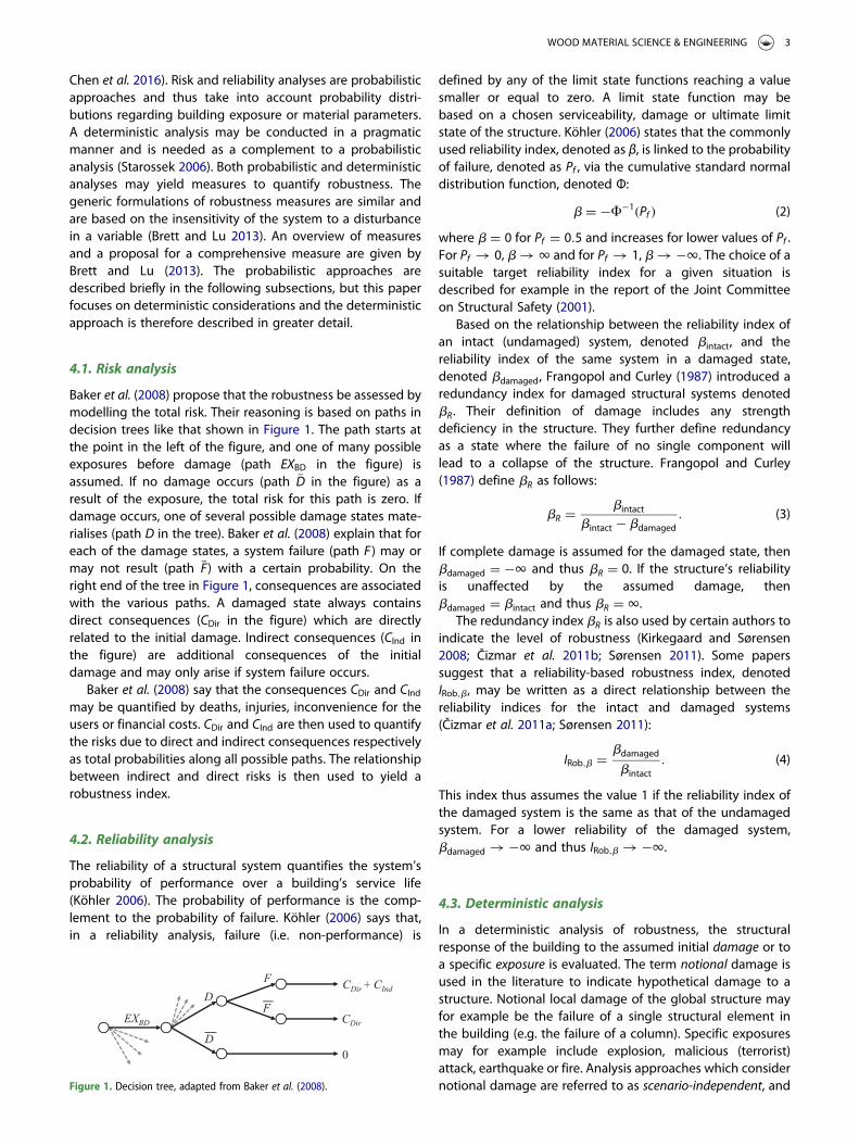
Baker et al. (2008) propose that the robustness be assessed bymodelling the total risk. Their reasoning is based on paths indecision trees like that shown in Figure 1. The path starts atthe point in the left of the figure, and one of many possibleexposures before damage (path EXBD in the figure) isassumed. If no damage occurs (path �D in the figure) as aresult of the exposure, the total risk for this path is zero. Ifdamage occurs, one of several possible damage states mate-rialises (path D in the tree). Baker et al. (2008) explain that foreach of the damage states, a system failure (path F ) may ormay not result (path �F) with a certain probability. On theright end of the tree in Figure 1, consequences are associatedwith the various paths. A damaged state always containsdirect consequences (CDir in the figure) which are directlyrelated to the initial damage. Indirect consequences (CInd inthe figure) are additional consequences of the initialdamage and may only arise if system failure occurs.
Baker et al. (2008) say that the consequences CDir and CIndmay be quantified by deaths, injuries, inconvenience for theusers or financial costs. CDir and CInd are then used to quantifythe risks due to direct and indirect consequences respectivelyas total probabilities along all possible paths. The relationshipbetween indirect and direct risks is then used to yield arobustness index.
4.2. Reliability analysis
The reliability of a structural system quantifies the system’sprobability of performance over a building’s service life(Köhler 2006). The probability of performance is the comp-lement to the probability of failure. Köhler (2006) says that,in a reliability analysis, failure (i.e. non-performance) is
defined by any of the limit state functions reaching a valuesmaller or equal to zero. A limit state function may bebased on a chosen serviceability, damage or ultimate limitstate of the structure. Köhler (2006) states that the commonlyused reliability index, denoted as β, is linked to the probabilityof failure, denoted as Pf , via the cumulative standard normaldistribution function, denoted Φ:
b = −F−1(Pf ) (2)
where b = 0 for Pf = 0.5 and increases for lower values of Pf .For Pf � 0, b � 1 and for Pf � 1, b � −1. The choice of asuitable target reliability index for a given situation isdescribed for example in the report of the Joint Committeeon Structural Safety (2001).
Based on the relationship between the reliability index ofan intact (undamaged) system, denoted bintact, and thereliability index of the same system in a damaged state,denoted bdamaged, Frangopol and Curley (1987) introduced aredundancy index for damaged structural systems denotedbR. Their definition of damage includes any strengthdeficiency in the structure. They further define redundancyas a state where the failure of no single component willlead to a collapse of the structure. Frangopol and Curley(1987) define bR as follows:
bR =bintact
bintact − bdamaged. (3)
If complete damage is assumed for the damaged state, thenbdamaged = −1 and thus bR = 0. If the structure’s reliabilityis unaffected by the assumed damage, thenbdamaged = bintact and thus bR = 1.
The redundancy index bR is also used by certain authors toindicate the level of robustness (Kirkegaard and Sørensen2008; Čizmar et al. 2011b; Sørensen 2011). Some paperssuggest that a reliability-based robustness index, denotedIRob,b, may be written as a direct relationship between thereliability indices for the intact and damaged systems(Čizmar et al. 2011a; Sørensen 2011):
IRob,b = bdamaged
bintact. (4)
This index thus assumes the value 1 if the reliability index ofthe damaged system is the same as that of the undamagedsystem. For a lower reliability of the damaged system,bdamaged � −1 and thus IRob,b � −1.
4.3. Deterministic analysis
In a deterministic analysis of robustness, the structuralresponse of the building to the assumed initial damage or toa specific exposure is evaluated. The term notional damage isused in the literature to indicate hypothetical damage to astructure. Notional local damage of the global structure mayfor example be the failure of a single structural element inthe building (e.g. the failure of a column). Specific exposuresmay for example include explosion, malicious (terrorist)attack, earthquake or fire. Analysis approaches which considernotional damage are referred to as scenario-independent, andFigure 1. Decision tree, adapted from Baker et al. (2008).
WOOD MATERIAL SCIENCE & ENGINEERING 3
approaches which consider a specific exposure as scenario-dependent (Arup 2011).
In a scenario-independent approach, the exposure whichcaused the initial damage is disregarded in the analysis inorder to evaluate the building’s built-in ability to sustaindamage of any type (Arup 2011). The sudden removal of aload-bearing element is the most accepted method in a scen-ario-independent approach (Arup 2011). ISE (2010) indicatethat the removal of a load-bearing element may refer to acolumn, wall or support structure for columns or walls.Elements should be removed one at a time, on each storey,unless it can be shown that element removal in differentstoreys leads to similar results.
In a scenario-dependent analysis, a specific exposure on abuilding is considered. This analysis may be used to demon-strate structural robustness in specific events, whereas thescenario-independent approach may be used to establish abaseline of robustness (Arup 2011). This paper focuses onscenario-independent approaches.
4.3.1. Alternative load path analysisTo analyse the structural response of a building to thenotional removal of an element, an alternative load pathanalysis (ALPA) may be performed (Ellingwood et al. 2007;Arup 2011; U.S. DoD 2016). The objective of an ALPA is toassess how loads are absorbed along alternative paths inthe structure after the initial damage, and to quantify theextent of the collapse progression.
4.3.1.1 General concept. In a model of the building, a load-bearing element is notionally removed, and the structuralconsequences are studied. As the notional removal iscarried out in a sudden manner, dynamic load effectsshould be taken into account (Arup 2011). Debris loadingfrom falling parts during collapse need to be taken intoaccount in some cases (ISE 2010; Arup 2011). The extent ofthe removal is often specified by the nominal length. Thislength usually does not exceed 2.25H where H is the storeyheight, but for an external masonry, timber or steel studwall, the length between vertical lateral supports (e.g.columns or perpendicular walls) should be used (Eurocode 12006; ISE 2010; Arup 2011). The choice of removed elementscan be summarised as follows (ISE 2010):
. The removed element may be a support column, thenominal length of a load-bearing wall section, or structuressupporting these two elements.
. Elements should be removed one at a time, on each storey,unless it can be shown that element removal on differentstoreys leads to similar results.
. If several columns are located within a diameter of nominallength, they should be removed simultaneously.
. In corners, the length of load-bearing walls removedshould be H in each direction, but not less than the dis-tance between expansion or control joints.
A reason why to use 2.25H as the maximum removallength for load-bearing walls was difficult to find in the litera-ture. Since this value represents an upper limit, it remains
generally unclear how much wall length should beremoved. Using the maximum would be conservative, butin some cases the removal of a length between verticallateral supports could be sufficient, even for internal walls.Arup (2011) argues that the design against the removal of asingle column or a nominal length of a load-bearing wallresults in sufficient robustness for most buildings, and thatthese uniform removals could standardise robustness.
Detailed guidance regarding loads which should beapplied in an ALPA can for example be found in the GSA(2013) and U.S. DoD (2016) codes. In these codes, thegravity loads for floor areas above the removed column orwall section are generally a combination of dead load andlive load (or snow load). In case of static calculations, theloads are multiplied by a dynamic load factor (DLF) toaccount for dynamic load effects. See Section 5.4 for moredetailed information about the specific loads.
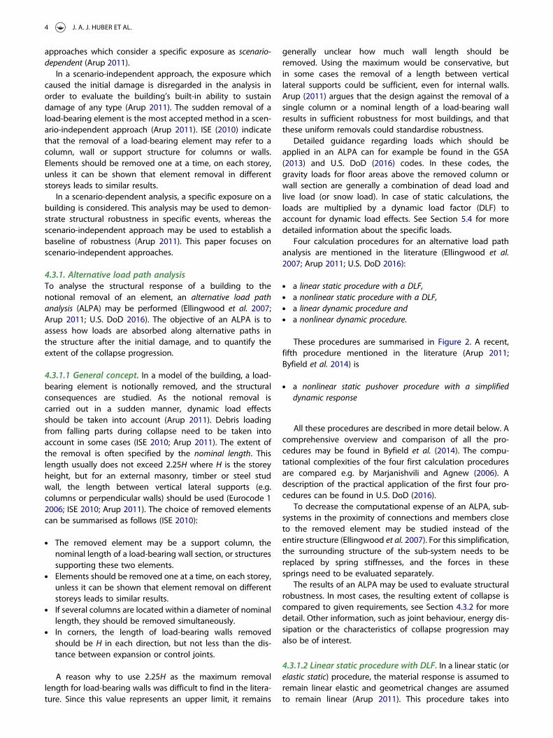
Four calculation procedures for an alternative load pathanalysis are mentioned in the literature (Ellingwood et al.2007; Arup 2011; U.S. DoD 2016):
. a linear static procedure with a DLF,
. a nonlinear static procedure with a DLF,
. a linear dynamic procedure and
. a nonlinear dynamic procedure.
These procedures are summarised in Figure 2. A recent,fifth procedure mentioned in the literature (Arup 2011;Byfield et al. 2014) is
. a nonlinear static pushover procedure with a simplifieddynamic response
All these procedures are described in more detail below. Acomprehensive overview and comparison of all the pro-cedures may be found in Byfield et al. (2014). The compu-tational complexities of the four first calculation proceduresare compared e.g. by Marjanishvili and Agnew (2006). Adescription of the practical application of the first four pro-cedures can be found in U.S. DoD (2016).
To decrease the computational expense of an ALPA, sub-systems in the proximity of connections and members closeto the removed element may be studied instead of theentire structure (Ellingwood et al. 2007). For this simplification,the surrounding structure of the sub-system needs to bereplaced by spring stiffnesses, and the forces in thesesprings need to be evaluated separately.
The results of an ALPA may be used to evaluate structuralrobustness. In most cases, the resulting extent of collapse iscompared to given requirements, see Section 4.3.2 for moredetail. Other information, such as joint behaviour, energy dis-sipation or the characteristics of collapse progression mayalso be of interest.
4.3.1.2 Linear static procedure with DLF. In a linear static (orelastic static) procedure, the material response is assumed toremain linear elastic and geometrical changes are assumedto remain linear (Arup 2011). This procedure takes into
4 J. A. J. HUBER ET AL.
account dynamic inertial effects by increasing the staticallyapplied gravity load by a DLF of usually 2.0 (Ellingwoodet al. 2007; Arup 2011). A linear elastic calculation does nottake into consideration plasticity or buckling, and thereforeneither any load distribution mechanisms which are favour-able for collapse resistance (Ellingwood et al. 2007; Arup2011). This procedure may produce highly conservativeresults, but it is methodologically and computationallysimpler than the other procedures (Arup 2011).
Ellingwood et al. (2007) note that the linear elastic pro-cedure may be conducted in an iterative manner by replacingor removing structural elements which have reached theircapacity during the analysis. Byfield et al. (2014) note thatelements which have reached their capacity in shear are com-pletely removed from the analysis whereas if an element’smoment capacity is reached, it may be replaced by a hingeat the assumed location of yielding, loaded with a momentcorresponding to the ultimate moment capacity of theelement.
4.3.1.3 Nonlinear static procedure with DLF. A nonlinearstatic procedure may take into account plastic material behav-iour and large geometric changes. As the dissipation ofenergy in plastic strains can be considered, load distributionmechanisms which may enhance collapse resistance (seeSection 5.2.1) can be taken into consideration (Arup 2011).To include dynamic effects, DLFs are used which are ingeneral lower than those for the linear static procedure(Arup 2011).
Marjanishvili (2004) notes that a nonlinear static analysisfor vertical loads after element removal is sometimes referredto as pushover analysis. Although this term seems non-intui-tive, it seems to be established in the literature. Ellingwoodet al. (2007) note that a load–displacement curve for gravityloads after element removal may be called a push-down curve.
4.3.1.4 Linear dynamic procedure. The linear dynamic pro-cedure extends the linear static procedure by taking intoaccount the structure’s time history response (Ellingwood
et al. 2007; Arup 2011). Dynamic load effects are consideredby this procedure. Like the linear static procedure, the lineardynamic procedure produces highly conservative resultsbecause plasticity is not considered (Arup 2011). The lineardynamic procedure is rather unusual for ALPA (Arup 2011;Byfield et al. 2014), but it may nevertheless be used in prep-aration for a nonlinear dynamic analysis (Arup 2011).
4.3.1.5 Nonlinear dynamic procedure. The nonlineardynamic procedure extends the nonlinear static procedureby taking into account the structure’s time history response(Ellingwood et al. 2007; Arup 2011). It is the most rigorousand accurate of all the procedures. Accurate materialmodels for ductile and brittle behaviour are required (Elling-wood et al. 2007), and beneficial load distribution mechan-isms (see Section 5.2.1) and dynamic inertial effects aretaken into account (Arup 2011), as well as damping andmaterial strain rate effects (Byfield et al. 2014). A nonlineardynamic calculation is both complex and computationallyexpensive (Ellingwood et al. 2007; Arup 2011).
4.3.1.6 Nonlinear static pushover procedure with simplifieddynamic response. This procedure uses the nonlinear staticcalculation procedure to establish the load-displacementbehaviour under different load levels after removal of anelement, which is referred to as a pushover analysis. Afterremoval of the element, the energy balance between thegravitational energy release and energy absorption in thestructure is used to calculate the dynamic displacement(Byfield et al. 2014).
A systematic approach to this procedure was first pre-sented by Izzuddin et al. (2008). Other names for the pro-cedure are simplified dynamic assessment (Kwasniewski et al.2009) and energy balance procedure (Byfield et al. 2014). Izzud-din et al. (2008) list three steps in the analysis:
(i) nonlinear static response of the damaged structureunder gravity loading,
Figure 2. Analysis procedures for an ALPA.
WOOD MATERIAL SCIENCE & ENGINEERING 5
(ii) simplified dynamic assessment to establish themaximum dynamic response as a result of a suddencolumn loss and
(iii) ductility assessment of the connections.
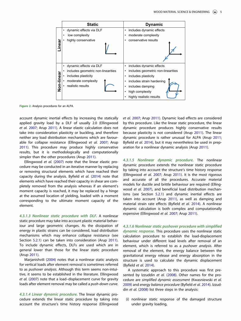
The relationship between the static load and the displace-ment of the position above the failed element is first estab-lished by gradually increasing the gravity load P in anonlinear static calculation procedure (Izzuddin et al. 2008;Byfield et al. 2014). The mass above the removed element isassumed to move in a single dominant displacement modeas a lumped mass point, which results in a single dominatingdeformation mode, corresponding to a single degree offreedom (SDOF) system (Arup 2011). The analysis may be con-ducted on subsystems of the entire structure where connec-tions to the surrounding structure are replaced by springs.Subsystems may consist of building bays, multiple floorsabove the removed element, single floors or single beams(Izzuddin et al. 2008; Byfield et al. 2014). Figure 3 shows amodel for a pushover analysis of a building subsystem. Inthe figure, P is the gravity load, u the vertical displacementabove the removed element and M the lumped mass. A cor-responding load-displacement curve is shown in Figure 4(a),illustrated by the continuous curve.
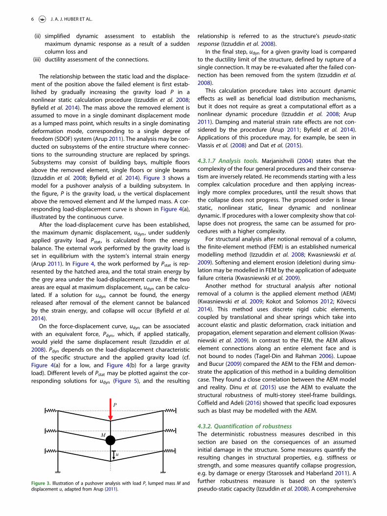
After the load-displacement curve has been established,the maximum dynamic displacement, udyn, under suddenlyapplied gravity load Pstat, is calculated from the energybalance. The external work performed by the gravity load isset in equilibrium with the system’s internal strain energy(Arup 2011). In Figure 4, the work performed by Pstat is rep-resented by the hatched area, and the total strain energy bythe grey area under the load-displacement curve. If the twoareas are equal at maximum displacement, udyn can be calcu-lated. If a solution for udyn cannot be found, the energyreleased after removal of the element cannot be balancedby the strain energy, and collapse will occur (Byfield et al.2014).
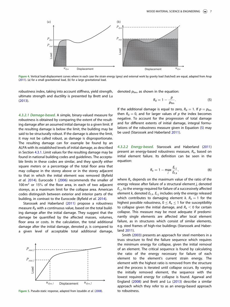
On the force-displacement curve, udyn can be associatedwith an equivalent force, Pdyn, which, if applied statically,would yield the same displacement result (Izzuddin et al.2008). Pdyn depends on the load-displacement characteristicof the specific structure and the applied gravity load (cf.Figure 4(a) for a low, and Figure 4(b) for a large gravityload). Different levels of Pstat may be plotted against the cor-responding solutions for udyn (Figure 5), and the resulting
relationship is referred to as the structure’s pseudo-staticresponse (Izzuddin et al. 2008).
In the final step, udyn for a given gravity load is comparedto the ductility limit of the structure, defined by rupture of asingle connection. It may be re-evaluated after the failed con-nection has been removed from the system (Izzuddin et al.2008).
This calculation procedure takes into account dynamiceffects as well as beneficial load distribution mechanisms,but it does not require as great a computational effort as anonlinear dynamic procedure (Izzuddin et al. 2008; Arup2011). Damping and material strain rate effects are not con-sidered by the procedure (Arup 2011; Byfield et al. 2014).Applications of this procedure may, for example, be seen inVlassis et al. (2008) and Dat et al. (2015).
4.3.1.7 Analysis tools. Marjanishvili (2004) states that thecomplexity of the four general procedures and their conserva-tism are inversely related. He recommends starting with a lesscomplex calculation procedure and then applying increas-ingly more complex procedures, until the result shows thatthe collapse does not progress. The proposed order is linearstatic, nonlinear static, linear dynamic and nonlineardynamic. If procedures with a lower complexity show that col-lapse does not progress, the same can be assumed for pro-cedures with a higher complexity.
For structural analysis after notional removal of a column,the finite-element method (FEM) is an established numericalmodelling method (Izzuddin et al. 2008; Kwasniewski et al.2009). Softening and element erosion (deletion) during simu-lation may be modelled in FEM by the application of adequatefailure criteria (Kwasniewski et al. 2009).
Another method for structural analysis after notionalremoval of a column is the applied element method (AEM)(Kwasniewski et al. 2009; Kokot and Solomos 2012; Kövecsi2014). This method uses discrete rigid cubic elements,coupled by translational and shear springs which take intoaccount elastic and plastic deformation, crack initiation andpropagation, element separation and element collision (Kwas-niewski et al. 2009). In contrast to the FEM, the AEM allowselement connections along an entire element face and isnot bound to nodes (Tagel-Din and Rahman 2006). Lupoaeand Bucur (2009) compared the AEM to the FEM and demon-strate the application of this method in a building demolitioncase. They found a close correlation between the AEM modeland reality. Dinu et al. (2015) use the AEM to evaluate thestructural robustness of multi-storey steel-frame buildings.Coffield and Adeli (2016) showed that specific load exposuressuch as blast may be modelled with the AEM.
4.3.2. Quantification of robustnessThe deterministic robustness measures described in thissection are based on the consequences of an assumedinitial damage in the structure. Some measures quantify theresulting changes in structural properties, e.g. stiffness orstrength, and some measures quantify collapse progression,e.g. by damage or energy (Starossek and Haberland 2011). Afurther robustness measure is based on the system’spseudo-static capacity (Izzuddin et al. 2008). A comprehensive
Figure 3. Illustration of a pushover analysis with load P, lumped mass M anddisplacement u, adapted from Arup (2011).
6 J. A. J. HUBER ET AL.
robustness index, taking into account stiffness, yield strength,ultimate strength and ductility is presented by Brett and Lu(2013).
4.3.2.1 Damage-based. A simple, binary-valued measure forrobustness is obtained by comparing the extent of the result-ing damage after an assumed initial damage to a given limit. Ifthe resulting damage is below the limit, the building may besaid to be structurally robust. If the damage is above the limit,it may not be called robust, as damage is disproportionate.The resulting damage can for example be found by anALPA with its established levels of initial damage, as describedin Section 4.3.1. Limit values for the resulting damage may befound in national building codes and guidelines. The accepta-ble limits in these codes are similar, and they specify eithersquare meters or a percentage of the total floor area thatmay collapse in the storey above or in the storey adjacentto that in which the initial element was removed (Byfieldet al. 2014). Eurocode 1 (2006) recommends the smaller of100m2 or 15% of the floor area, in each of two adjacentstoreys, as a maximum limit for the collapse area. Americancodes distinguish between exterior and interior parts of thebuilding, in contrast to the Eurocode (Byfield et al. 2014).
Starossek and Haberland (2011) propose a robustnessmeasure Rd with a continuous value, based on the total build-ing damage after the initial damage. They suggest that thedamage be quantified by the affected masses, volumes,floor area or costs. In the calculation, the total additionaldamage after the initial damage, denoted p, is compared toa given level of acceptable total additional damage,
denoted plim, as shown in the equation:
Rd = 1− pplim
. (5)
If the additional damage is equal to zero, Rd = 1. If p = plimthen Rd = 0, and for larger values of p the index becomesnegative. To account for the progression of total damageand for different extents of initial damage, integral formu-lations of the robustness measure given in Equation (5) maybe used (Starossek and Haberland 2011).
4.3.2.2 Energy-based. Starossek and Haberland (2011)present an energy-based robustness measure, Re, based oninitial element failure. Its definition can be seen in theequation:
Re = 1−maxj
Er,jEf,k
, (6)
where Re depends on the maximum value of the ratio of theenergy release after failure of a structural element j, denotedEr,j , to the energy required for failure of a successively affectedelement k, denoted Ef,k . Er,j includes only the energy releasedwhich contributes to damaging element k. Re = 1 for thehighest possible robustness, 0 ≤ Re ≤ 1 for the susceptibilityto collapse given the initial damage, and Re , 0 for certaincollapse. This measure may be most adequate if predomi-nantly single elements are affected after local elementfailure, as in structures which consist of similar elements,e.g. steel frames of high-rise buildings (Starossek and Haber-land 2011).
Smith (2003) presents an approach for steel members in atruss structure to find the failure sequence which requiresthe minimum energy for collapse, given the initial removalof an element. The critical sequence is found by calculatingthe ratio of the energy necessary for failure of eachelement to the element’s current strain energy. Theelement with the highest ratio is removed from the structureand the process is iterated until collapse occurs. By varyingthe initially removed element, the sequence with thelowest required energy for collapse is found. Agarwal andEngland (2008) and Brett and Lu (2013) describe a similarapproach which they refer to as an energy-based approachto robustness.
(a) (b)
Figure 4. Vertical load-displacement curves where in each case the strain energy (grey) and external work by gravity load (hatched) are equal, adapted from Arup(2011). (a) for a small gravitational load, (b) for a large gravitational load.
Figure 5. Pseudo-static response, adapted from Izzuddin et al. (2008).
WOOD MATERIAL SCIENCE & ENGINEERING 7
4.3.2.3 Stiffness-based. Starossek and Haberland (2011)present a stiffness-based measure of robustness, denoted asRS, defined as in the equation:
Rs = minj
det Kj
det K0, (7)
where RS depends on the lowest ratio between the determi-nant of the active system stiffness matrix of the undamagedstructure, denoted K0, to the determinant of the stiffnessmatrix of the structure after removing the connection j,denoted Kj . Rs may be calibrated to take the value 1 formaximum robustness and 0 for a lack thereof. Brett and Lu(2013) present similar stiffness-based measures based on nor-malised stiffness matrices of the damaged and undamagedstructures. Starossek and Haberland (2011) claim that a stiff-ness-based measure may be adequate only for buildingsprone to zipper-type collapse, which is further explained inStarossek (2007) and Kokot and Solomos (2012).
4.3.2.4 Strength-based. Sørensen (2011) proposes a robust-ness measure based on reserve strength, using the ReserveStrength Ratio, RSR, which is the ratio of the characteristicstrength of the system, Rc , to the load that would lead tothe system’s collapse, Sc :
RSR = RcSc. (8)
The measure for robustness given by Sørensen (2011) is theResidual Influence Factor (RIF) defined for each structuralelement i as in the equation:
RIFi = RSRfail,iRSRintact
, (9)
where RIFi is the ratio of the RSR-value for the system with thestructural element i removed, RSRfail,i , to the RSR-value of theintact system, RSRintact. The value of RIFi lies in the interval[0, 1] where 1 indicates full and 0 absent robustness. Itmeasures how the loss of an element affects the globalstrength capacity. Although not explicitly mentioned bySørensen (2011), it may be assumed that the lowest RIF-value for the different removed elements should be used tomeasure the robustness of the entire system and to governdesign.
A similar assessment of reserve factors to measure robust-ness is given by Brett and Lu (2013), who use strength reservefactors which relate the ultimate strength of structuralmembers to their required strength in the structure. Othermeasures of this kind are the Demand–Capacity Ratio (DCR)which is for example used in U.S. DoD (2016). DCRs are estab-lished as the ratio of resulting actions (internal forces andmoments) to the expected strength of structural elements.
4.3.2.5 Pseudo-static capacity. The pseudo-static capacity ofa system is defined as the gravity load above a notionallyremoved element, for which the resulting dynamic displace-ment is less than or equal to the system’s ductility limit (Izzud-din et al. 2008). The capacity may be obtained from thenonlinear static pushover procedure described in Section4.3.1. The relationship between the actual gravity loadabove the removed element and the pseudo-static capacityyields a limit-state which is proposed by Izzuddin et al.(2008) as a measure of robustness.
This robustness measure embodies a ductility-based DCR,as opposed to most of the force-based DCRs (Arup 2011). Itquantifies the structural system’s reserve ductility. The morereserves exist, the more robust is the structure.
5. Design in general
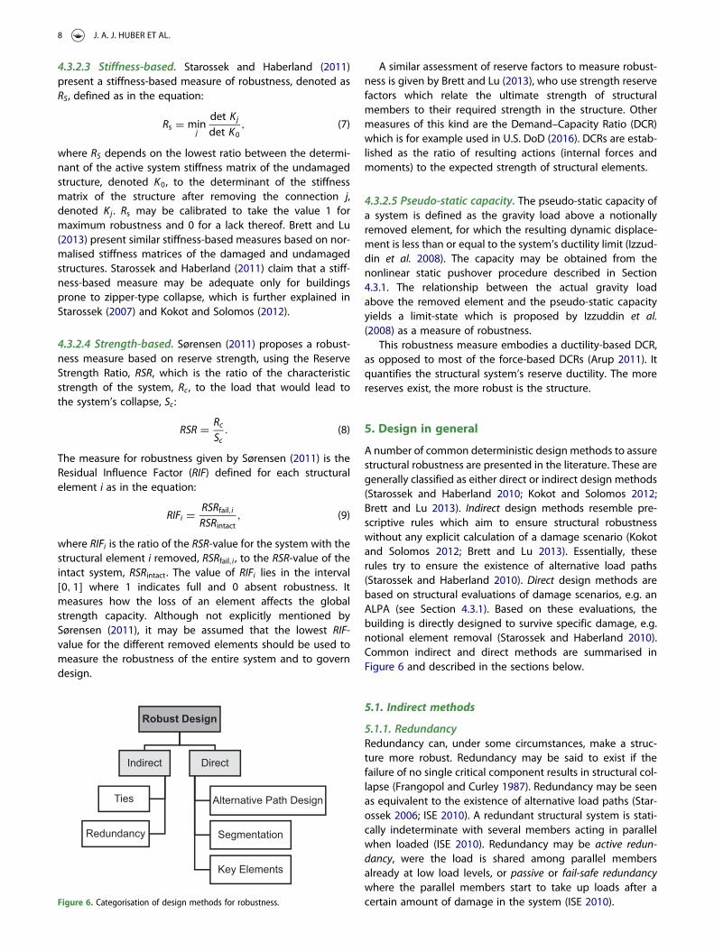
A number of common deterministic design methods to assurestructural robustness are presented in the literature. These aregenerally classified as either direct or indirect design methods(Starossek and Haberland 2010; Kokot and Solomos 2012;Brett and Lu 2013). Indirect design methods resemble pre-scriptive rules which aim to ensure structural robustnesswithout any explicit calculation of a damage scenario (Kokotand Solomos 2012; Brett and Lu 2013). Essentially, theserules try to ensure the existence of alternative load paths(Starossek and Haberland 2010). Direct design methods arebased on structural evaluations of damage scenarios, e.g. anALPA (see Section 4.3.1). Based on these evaluations, thebuilding is directly designed to survive specific damage, e.g.notional element removal (Starossek and Haberland 2010).Common indirect and direct methods are summarised inFigure 6 and described in the sections below.
5.1. Indirect methods
5.1.1. RedundancyRedundancy can, under some circumstances, make a struc-ture more robust. Redundancy may be said to exist if thefailure of no single critical component results in structural col-lapse (Frangopol and Curley 1987). Redundancy may be seenas equivalent to the existence of alternative load paths (Star-ossek 2006; ISE 2010). A redundant structural system is stati-cally indeterminate with several members acting in parallelwhen loaded (ISE 2010). Redundancy may be active redun-dancy, were the load is shared among parallel membersalready at low load levels, or passive or fail-safe redundancywhere the parallel members start to take up loads after acertain amount of damage in the system (ISE 2010).Figure 6. Categorisation of design methods for robustness.
8 J. A. J. HUBER ET AL.
In a redundant system, ductile behaviour should, if poss-ible, be preferred over brittle behaviour. Overloaded structuralelements should tolerate deformation without rupture toallow alternative load paths to engage in load-sharing (Knolland Vogel 2009). If a brittle element fails after overload, theremaining elements need to sustain all the overload, but ifthe failure is ductile, the remaining elements need only tosustain the additional load above the yield point of thefailed element (ISE 2010).
Redundancy may also have a detrimental effect on struc-tural robustness. If alternative load paths cannot sustain theresulting loads in a damaged structure, then redundancymay promote collapse progression (Starossek 2006). The det-rimental effects of structural redundancy for two timber hallbuildings are discussed by Munch-Andersen and Dietsch(2011), where it is claimed that a less redundant designwould have enhanced the robustness of one of the buildings.To avoid global redundancy and break continuity, buildingsegments may be structurally isolated from each other (Star-ossek 2006), see Section 5.2.2.
5.1.2. Continuity by tiesA common indirect method to enhance a building’s robust-ness is to provide structural continuity by horizontal and ver-tical ties. Ties are links between building components andtheir main function is to provide continuous load paths inthe structure, and to limit the displacement between the com-ponents (ISE 2010). Like redundancy, continuous ties increasethe possibility of load transfer in the event of local failure inthe structure (ISE 2010; Arup 2011; U.S. DoD 2016). Designinga building with ties may provide it with a minimum level ofrobustness and may therefore be adequate for low-risk build-ings (Arup 2011).
Ties should be continuous along the entire length, widthor height of the building, and their force paths should bestraight (ISE 2010). Ties may be formed by mechanical con-nections of single structural elements (Arup 2011). Horizontalties should be designed for each storey in continuous bandsat the building’s perimeter, and internally in the perpendicu-lar directions, with sufficient anchorage towards walls andconnections (ISE 2010). The horizontal tie forces required inEurocode 1 (2006) depend on the tie spacing, the span ofthe ties, the number of storeys and whether the ties areinternal or peripheral. Vertical ties should be continuousfrom top to bottom and well anchored to the foundation(ISE 2010). Vertical continuity should enable floors abovefailed vertical elements to be suspended from the tiesabove (Arup 2011). Vertical tie forces required in Eurocode 1(2006) depend on the building height in the case of framedbuildings, and on the wall dimensions in the case of load-bearing wall constructions.
There is some doubt as to whether tying alone is sufficientto ensure that a structure may span over a locally failed region(ISE 2010; Arup 2011). In order to ensure that alternative loadpaths develop, ductility would also need to be specified, but itis omitted in building codes (ISE 2010). The tying methoddoes not evaluate the building’s robustness before and afterthe implementation of the ties (Arup 2011).
5.2. Direct methods
5.2.1. Alternative load path designThe basis for this design method is an ALPA (see Section 4.3.1),where the collapse extent and the development of alternativeload paths after notional removal of an element can be calcu-lated. Alternative load paths are designed in the structure tobe activated and bridge local failure (Byfield et al. 2014). Thedesign may be improved until it matches any given require-ment for robustness, e.g. the amount of collapsed floor areaspecified in Eurocode 1 (2006). Characteristic aspects ofalternative load path design are described in this section.
5.2.1.1 Ductility. Ductility is the ability of a structure or amaterial to deform plastically under load without rupturing(ISE 2010). It allows the absorption of a load into plasticstrain energy (ISE 2010), and should be utilised for efficientalternative load path design (Arup 2011). Ductile failure in astructure is preferable to brittle failure because the failuremay be signalled by large deformations before collapseoccurs (ISE 2010). Plastic strain hardening after yielding inthe material may increase the resistance to loads at largedeformations (Arup 2011) and may be beneficial for robust-ness (Knoll and Vogel 2009).
A structural fuse element along an alternative load path is ameans to limit the force that may be transferred in thesepaths, and to keep the force at a specific level (Knoll andVogel 2009). The fuse element may tolerate large, inelasticdeformation and may therefore be used in a displacement-based design (e.g. seismic design) to dissipate energy (Knolland Vogel 2009; Branco and Neves 2011). These propertiesindicate that ductility plays a vital role in the design of afuse element. Khandelwal and El-Tawil (2011) suggest thatfuse elements used in seismic design may also be used toavoid collapse progression in a building. Fuse elements maybe used to avoid the transfer of destructive forces betweenbuilding compartments (Ellingwood et al. 2007), or toensure that a failing building compartment may safely discon-nect at a specified location (Starossek and Haberland 2010)(cf. the compartmentalisation approach in Section5.2.2).
The development of catenary action after element failure(described below) depends on the ductility supply in jointsand connections (ISE 2010). As was shown for the nonlinearstatic pushover procedure in Section 4.3.1, ductility isdesired to increase the capacity of the structure to withstanda suddenly applied load (Izzuddin et al. 2008). Designing astructure with excessively high strength may disturb theductile failure modes (ISE 2010).
5.2.1.2 Load distribution mechanisms. Some mechanismsare able to redistribute loads in the structure after localfailure and thus prevent collapse (Arup 2011). These mechan-isms depend mainly on material plasticity and geometric non-linearities (e.g. buckling). The most important mechanisms aredescribed below.
Catenary action or chain action is a mechanism which uti-lises the tensile capacity of a beam or floor to distribute aload above a removed element. For the mechanism todevelop, the connections need to allow sufficient rotation,
WOOD MATERIAL SCIENCE & ENGINEERING 9
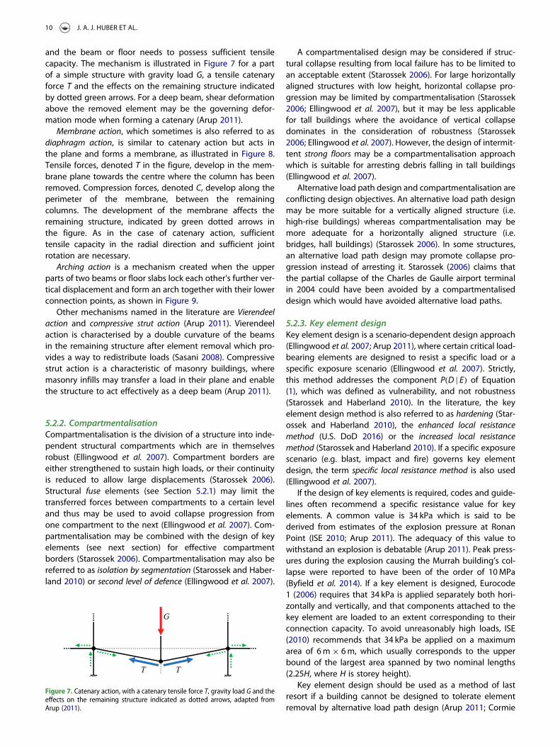
and the beam or floor needs to possess sufficient tensilecapacity. The mechanism is illustrated in Figure 7 for a partof a simple structure with gravity load G, a tensile catenaryforce T and the effects on the remaining structure indicatedby dotted green arrows. For a deep beam, shear deformationabove the removed element may be the governing defor-mation mode when forming a catenary (Arup 2011).
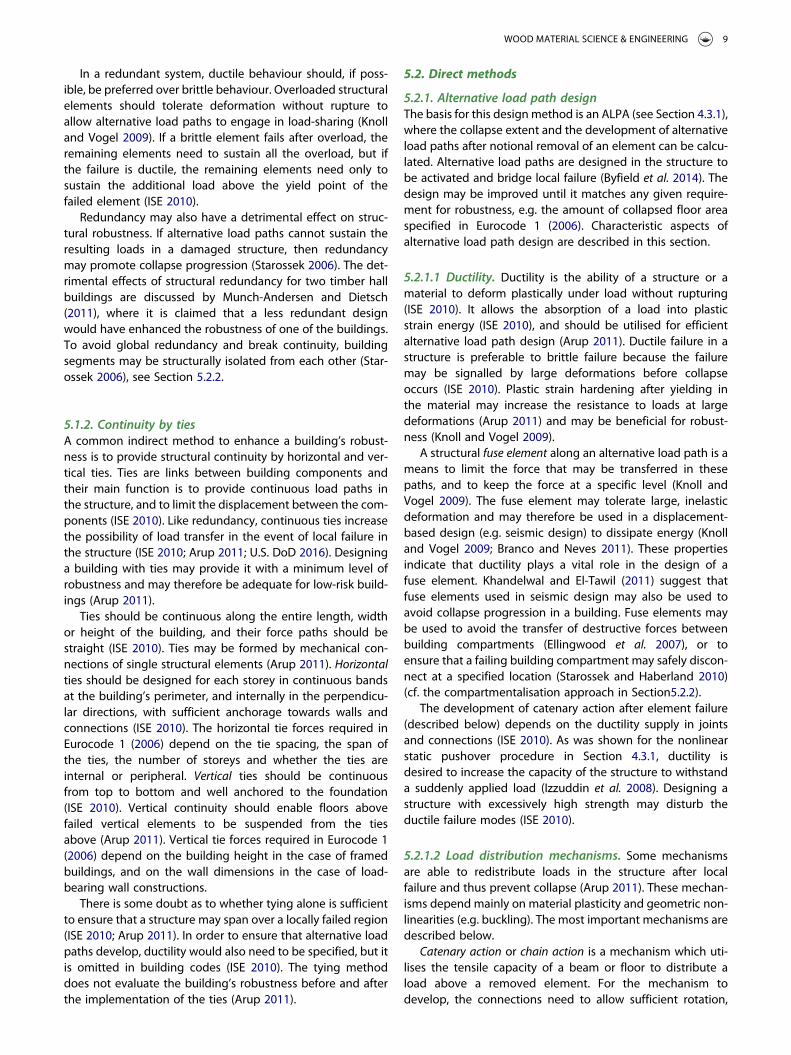
Membrane action, which sometimes is also referred to asdiaphragm action, is similar to catenary action but acts inthe plane and forms a membrane, as illustrated in Figure 8.Tensile forces, denoted T in the figure, develop in the mem-brane plane towards the centre where the column has beenremoved. Compression forces, denoted C, develop along theperimeter of the membrane, between the remainingcolumns. The development of the membrane affects theremaining structure, indicated by green dotted arrows inthe figure. As in the case of catenary action, sufficienttensile capacity in the radial direction and sufficient jointrotation are necessary.
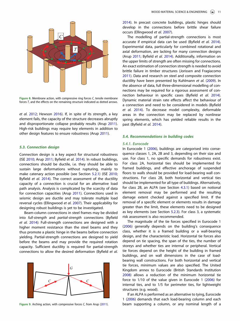
Arching action is a mechanism created when the upperparts of two beams or floor slabs lock each other’s further ver-tical displacement and form an arch together with their lowerconnection points, as shown in Figure 9.
Other mechanisms named in the literature are Vierendeelaction and compressive strut action (Arup 2011). Vierendeelaction is characterised by a double curvature of the beamsin the remaining structure after element removal which pro-vides a way to redistribute loads (Sasani 2008). Compressivestrut action is a characteristic of masonry buildings, wheremasonry infills may transfer a load in their plane and enablethe structure to act effectively as a deep beam (Arup 2011).
5.2.2. CompartmentalisationCompartmentalisation is the division of a structure into inde-pendent structural compartments which are in themselvesrobust (Ellingwood et al. 2007). Compartment borders areeither strengthened to sustain high loads, or their continuityis reduced to allow large displacements (Starossek 2006).Structural fuse elements (see Section 5.2.1) may limit thetransferred forces between compartments to a certain leveland thus may be used to avoid collapse progression fromone compartment to the next (Ellingwood et al. 2007). Com-partmentalisation may be combined with the design of keyelements (see next section) for effective compartmentborders (Starossek 2006). Compartmentalisation may also bereferred to as isolation by segmentation (Starossek and Haber-land 2010) or second level of defence (Ellingwood et al. 2007).
A compartmentalised design may be considered if struc-tural collapse resulting from local failure has to be limited toan acceptable extent (Starossek 2006). For large horizontallyaligned structures with low height, horizontal collapse pro-gression may be limited by compartmentalisation (Starossek2006; Ellingwood et al. 2007), but it may be less applicablefor tall buildings where the avoidance of vertical collapsedominates in the consideration of robustness (Starossek2006; Ellingwood et al. 2007). However, the design of intermit-tent strong floors may be a compartmentalisation approachwhich is suitable for arresting debris falling in tall buildings(Ellingwood et al. 2007).
Alternative load path design and compartmentalisation areconflicting design objectives. An alternative load path designmay be more suitable for a vertically aligned structure (i.e.high-rise buildings) whereas compartmentalisation may bemore adequate for a horizontally aligned structure (i.e.bridges, hall buildings) (Starossek 2006). In some structures,an alternative load path design may promote collapse pro-gression instead of arresting it. Starossek (2006) claims thatthe partial collapse of the Charles de Gaulle airport terminalin 2004 could have been avoided by a compartmentaliseddesign which would have avoided alternative load paths.
5.2.3. Key element designKey element design is a scenario-dependent design approach(Ellingwood et al. 2007; Arup 2011), where certain critical load-bearing elements are designed to resist a specific load or aspecific exposure scenario (Ellingwood et al. 2007). Strictly,this method addresses the component P(D | E) of Equation(1), which was defined as vulnerability, and not robustness(Starossek and Haberland 2010). In the literature, the keyelement design method is also referred to as hardening (Star-ossek and Haberland 2010), the enhanced local resistancemethod (U.S. DoD 2016) or the increased local resistancemethod (Starossek and Haberland 2010). If a specific exposurescenario (e.g. blast, impact and fire) governs key elementdesign, the term specific local resistance method is also used(Ellingwood et al. 2007).
If the design of key elements is required, codes and guide-lines often recommend a specific resistance value for keyelements. A common value is 34 kPa which is said to bederived from estimates of the explosion pressure at RonanPoint (ISE 2010; Arup 2011). The adequacy of this value towithstand an explosion is debatable (Arup 2011). Peak press-ures during the explosion causing the Murrah building’s col-lapse were reported to have been of the order of 10MPa(Byfield et al. 2014). If a key element is designed, Eurocode1 (2006) requires that 34 kPa is applied separately both hori-zontally and vertically, and that components attached to thekey element are loaded to an extent corresponding to theirconnection capacity. To avoid unreasonably high loads, ISE(2010) recommends that 34 kPa be applied on a maximumarea of 6m× 6m, which usually corresponds to the upperbound of the largest area spanned by two nominal lengths(2.25H, where H is storey height).
Key element design should be used as a method of lastresort if a building cannot be designed to tolerate elementremoval by alternative load path design (Arup 2011; Cormie
Figure 7. Catenary action, with a catenary tensile force T, gravity load G and theeffects on the remaining structure indicated as dotted arrows, adapted fromArup (2011).
10 J. A. J. HUBER ET AL.
et al. 2012; Hewson 2016). If, in spite of its strength, a keyelement fails, the capacity of the structure decreases abruptlyand disproportionate collapse probably results (Arup 2011).High-risk buildings may require key elements in addition toother design features to ensure robustness (Arup 2011).
5.3. Connection design
Connection design is a key aspect for structural robustness(ISE 2010; Arup 2011; Byfield et al. 2014). In robust buildings,connections should be ductile, i.e. they should be able tosustain large deformations without rupturing, mainly tomake catenary action possible (see Section 5.2.1) (ISE 2010;Byfield et al. 2014). The correct assessment of the ductilitycapacity of a connection is crucial for an alternative loadpath analysis. Analysis is complicated by the scarcity of datafor connection capacities (Arup 2011). Connections used inseismic design are ductile and may tolerate multiple loadreversal cycles (Ellingwood et al. 2007). Their applicability fordesigning robust buildings is yet to be investigated.
Beam-column connections in steel frames may be dividedinto full-strength and partial-strength connections (Byfieldet al. 2014): Full-strength connections are designed with ahigher moment resistance than the steel beams and theythus promote a plastic hinge in the beams before connectionyielding. Partial-strength connections are designed to yieldbefore the beams and may provide the required rotationcapacity. Sufficient ductility is required for partial-strengthconnections to allow the desired deformation (Byfield et al.
2014). In precast concrete buildings, plastic hinges shoulddevelop in the connections before brittle shear failureoccurs (Ellingwood et al. 2007).
The modelling of partial-strength connections is mostaccurate if empirical data can be used (Byfield et al. 2014).Experimental data, particularly for combined rotational andaxial deformation, are lacking for many connection designs(Arup 2011; Byfield et al. 2014). Additionally, information onthe upper limits of strength are often missing for connections.An exact estimation of connection strength is needed to avoidbrittle failure in timber structures (Jorissen and Fragiacomo2011). Data and research on steel and composite connectionductility have been presented by Kuhlmann et al. (2009). Inthe absence of data, full three-dimensional modelling of con-nections may be required for a rigorous assessment of con-nection behaviour in specific cases (Byfield et al. 2014).Dynamic material strain rate effects affect the behaviour ofa connection and need to be considered in models (Byfieldet al. 2014). To decrease model complexity, deformableareas in the connection may be replaced by nonlinearspring elements, which has yielded reliable results in thepast (Byfield et al. 2014).
5.4. Recommendations in building codes
5.4.1. EurocodeIn Eurocode 1 (2006), buildings are categorised into conse-quence classes 1, 2A, 2B and 3, depending on their size anduse. For class 1, no specific demands for robustness exist.For class 2A, horizontal ties should be implemented forframed buildings, and effective anchorage of suspendedfloors to walls should be provided for load-bearing wall con-structions. For class 2B, both horizontal and vertical tiesshould be implemented for all type of buildings. Alternatively,for class 2B, an ALPA (see Section 4.3.1) based on notionalelement removal may be performed and the resultingdamage extent checked against a specified limit. If theremoval of a specific element or elements results in damagegreater than the limit, these elements need to be designedas key elements (see Section 5.2.3). For class 3, a systematicrisk assessment is also recommended.
The magnitude of the tie forces specified in Eurocode 1(2006) generally depends on the building’s consequenceclass, whether it is a framed building or a wall-bearingdesign, and the characteristic load. Horizontal tie forces alsodepend on tie spacing, the span of the ties, the number ofstoreys and whether ties are internal or peripheral. Verticaltie forces depend on the height of the building in framedbuildings, and on wall dimensions in the case of load-bearing wall constructions. For both horizontal and verticaltie forces, minimum values are also specified. The UnitedKingdom annex to Eurocode (British Standards Institution2008) allows a reduction of the minimum horizontal tieforce to 1/10 of the value given in Eurocode 1 (2006) forinternal ties, and to 1/5 for perimeter ties, for lightweightstructures (e.g. wood).
If an ALPA is performed as an alternative to tying, Eurocode1 (2006) demands that each load-bearing column and eachbeam supporting a column, or any nominal length of a
Figure 8. Membrane action, with compressive ring forces C, tensile membraneforces T, and the effects on the remaining structure indicated as dotted arrows.
Figure 9. Arching action, with compressive forces C, from Arup (2011).
WOOD MATERIAL SCIENCE & ENGINEERING 11

load-bearing wall be removed one by one, on each storey. Anominal length should generally be 2.25H at most, where H isthe storey height. For external walls of timber, masonry orsteel studs, the nominal length should be taken as thelength between two vertical supports. The recommendedlimit for resulting damage is the smaller of 100m2 or 15%of the floor area, in each of two adjacent storeys. Eurocode1 (2006) gives no further guidance for the conduction of anALPA, e.g. which procedures to use, which loads and DLFsto assume, or how the connections should be treated.
For key elements, if they are required, Eurocode 1 (2006)demands that they withstand 34 kPa, acting both horizontallyand vertically, in one direction at a time. The key elementshould also be able to withstand any connected componentbeing loaded with the ultimate strength of the componentand its connection.
5.4.2. U.S. codesGSA (2013) and U.S. DoD (2016) divide buildings into risk cat-egories I to IV. For category I, no specific requirements exist.For category II, two alternative approaches are accepted.The first is to provide the structure with horizontal and verticalties, and to provide the corner elements (columns or walls)together with their neighbouring elements with enhancedlocal resistance (cf. key elements). The second alternative isto perform an ALPA and demonstrate that the structure canbridge over notionally removed elements. For category III,an ALPA should be performed, and all perimeter elementson the first storey should be designed with enhanced localresistance. For category IV, ties should be provided, an ALPAshould be performed, and all perimeter elements on thefirst storey should be designed with enhanced localresistance.
The required tie forces in U.S. DoD (2016) generally dependon the floor loads, tie spacing and a material-specific over-strength factor. The ties are also required to be capable ofrotating 11.3 degrees while carrying the tie forces. U.S. DoD(2016) gives detailed and pedagogic guidance on the calcu-lation of floor loads and tie forces for different buildingdesigns. Explicit minimum values for tie forces are notspecified.
The locations of column or wall removals in an ALPA arespecified for each risk category. On the perimeter, at leastthe columns in the corners and in the middle of the edgesneed to be removed. For walls, a length of at most 2Hshould be removed, where H is the storey height. In corners,a length of H in each direction should be removed. Removallocations may be omitted if results similar to those obtainedin other locations can be expected. The gravity loads forfloor areas above the removed column or wall, G, are generallyspecified in GSA (2013) and U.S. DoD (2016) in the format
G = V[1.2D+ (0.5L or 0.2S)], (10)
where D is the dead load, L is the live load and S is the snowload. Ω is a DLF and its value depends on the procedureapplied for the ALPA. For the remaining floor areas, notabove the removed column or wall, G should be appliedwith V = 1. In the nonlinear dynamic procedure, Ω isomitted and G should be applied to the entire structure.
ALPAs are also exemplified in the code for different buildingsystems and materials.
To check the design in an ALPA, U.S. DoD (2016)implements strength reduction and load increase factors tocompare strength supply to strength demand for all structuralelements. In contrast to Eurocode, the application of linearstatic, nonlinear static and nonlinear dynamic calculation pro-cedures for an ALPA are described, with additional guidanceon software implementation. Structural elements, com-ponents and connections are classified as primary if theyprovide the resistance capacity after element removal, andas secondary if they do not. All component actions in anALPA are also classified as deformation- or force-controlled,depending on the component’s force–displacement behav-iour. U.S. DoD (2016) gives detailed guidance on the calcu-lation of strength and deformation capacities. The capacitiesgenerally depend on the analysis procedure, whether anaction is force- or deformation-controlled, and on thematerial. For a robust building, the strengths of bothprimary and secondary elements, components and connec-tions need to fulfil the demands for deformation- and force-controlled actions after element removal, in contrast to Euro-code where an acceptable collapse area is defined.
U.S. DoD (2016) does not provide explicit load values forthe design of elements with enhanced local resistance.Rather, guidance is given as to how to design these elementsto fail in bending prior to failing in shear, to promote a ductilefailure mode.
5.4.3. ComparisonsSeveral building standards describe the tying method, ALPAand key element design as valid design methods for structuralrobustness (Byfield et al. 2014). The limits for admissible col-lapse after element removal are similar, a comparison hasbeen made by Byfield et al. (2014). Both Eurocode 1 (2006)and U.S. DoD (2016) note that an ALPA would be the mostpractical choice for load-bearing wall structures of risk cat-egories 2B and II.
6. Timber buildings
6.1. Collapse in timber structures
Failure causes for a number of timber structures are describedby Frühwald Hansson (2011) and Dietsch (2011). Both identifythat most of the failures were caused by design errors andthat most failures were in general related to gross humanerrors. Dietsch (2011) argues that errors during design willprobably have a repetitive effect on all affected elementsand thus lead to global effects in the structure. The investi-gations of Frühwald Hansson (2011) showed that failuremost frequently occurred in beams, trusses and the bracingsystem. Most failures could be traced back to one of the fol-lowing reasons:
. insufficient bracing,
. tensile perpendicular-to-grain failure,
. ignoring moisture effects and
. negligent joint design and assembly.
12 J. A. J. HUBER ET AL.
Two well-known cases of collapse in timber structures arethe Bad Reichenhall Ice-Arena in 2006 (Čizmar et al. 2011a;Dietsch 2011; Munch-Andersen and Dietsch 2011) and theSiemens Arena in Ballerup 2001 (Hansson and Larsen 2005;Čizmar et al. 2011a; Dietsch 2011).
6.2. Structural robustness analysis
Most robustness analyses for timber buildings seem to bebased on a probabilistic reliability analysis (see Section 4). Areliability analysis of a timber hall building was for exampleconducted by Kirkegaard and Sørensen (2008) and Rajčićet al. (2010). Structural elements were notionally removedand the resulting change in the reliability index was quanti-fied. The effects of considering connection ductility in areliability analysis of a timber structure were studied by Kirke-gaard et al. (2011), who found that a small increase in ductilityled to a large increase in the system reliability index. Athorough treatment of modelling reliability in timber struc-tures is given by Köhler (2006).
Deterministic analyses of the structural robustness oftimber buildings are more difficult to find in the literature. Adeterministic evaluation of different purlin systems in alarge-span timber roof structure was conducted by Dietsch(2011), where different purlins between two supports anddifferent main beams acting as supports were notionallyremoved and the consequences studied. An example of anALPA for a three-storey light timber-frame building is con-ducted in U.S. DoD (2016), where a linear static procedure isfollowed and four different wall removal scenarios are evalu-ated. The length of the removed wall elements in this exampleis twice the storey height.
6.3. Design for structural robustness
6.3.1. Timber in general6.3.1.1 Material properties. The low density of timber com-pared to its mechanical properties may be considered to bean advantage with regard to structural robustness (Hewson2016). Lower weight leads to lower inertial effects andsmaller debris loads during collapse. In tension, bendingand shear, timber usually fails in a brittle mode. In com-pression, it exhibits some ductile behaviour (Thelanderssonand Honfi 2009). Timber may therefore possess less abilityto develop catenary action after element removal (Hewson2016), and redundancy concepts may thus be harder toinclude in timber designs (Thelandersson and Honfi 2009).In tensile perpendicular-to-grain direction, ductility may forexample be increased by reinforcements with metal screwsor fibre composites (Thelandersson and Honfi 2009).
6.3.1.2 Connections and ductility. Connections in timberbuildings are the critical regions for load transfer (Hewson2016). Kirkegaard et al. (2011) compared damaged and unda-maged timber structures and concluded that the robustnessof these structures may be significantly increased by increas-ing ductility in the system. Ductility in a timber structure maypredominantly be supplied by plastic behaviour of the con-nections (Smith and Frangi 2008; Thelandersson and Honfi
2009; Brühl et al. 2011; Jorissen and Fragiacomo 2011). Yield-ing of metal connectors together with compressive failure ofthe wood are the main sources of ductility in timber joints(Thelandersson and Honfi 2009). The ductility of metal fasten-ers in timber has been assessed by Kuhlmann et al. (2006),Malo et al. (2011) and Brühl et al. (2011, 2014). Stehn andBörjes (2004) showed that the deformation and load-carryingcapacity of timber trusses may be increased by using ductilesteel connectors. Wood constructions composed of manymetal fasteners, e.g. light timber-frames, may be expectedto exhibit ductile behaviour (Thelandersson and Honfi 2009).
There are several definitions of ductility, all related tostress, strain or energy, which may be useful in different situ-ations (Malo et al. 2011). For connection design, definitionsreferring to absolute values of rotation and displacementmay be the most applicable (Jorissen and Fragiacomo 2011).Ductility may further be divided into static ductility for con-stant loads, and dynamic ductility for cyclic loads (Jorissenand Fragiacomo 2011).
Capacity-based designmay be used to ensure ductile failurein timber structures and thus the possibility of load distri-bution after local failure. In this design approach, the strengthcapacity of ductile components is less than the capacity ofbrittle components, i.e. plastic yielding in connections willoccur before brittle failure of the members (Jorissen and Fra-giacomo 2011; Lawrence 2014). In this context, an over-strength factor may be used to quantify how much strongerbrittle elements are than ductile elements (Brühl et al. 2014).Brühl et al. (2011) have shown that it is possible to implementa desired level of fastener ductility in timber structures.Capacity-based design has so far been used in the seismicdesign of timber buildings (Jorissen and Fragiacomo 2011).
6.3.1.3 Design. The many interconnections in timber build-ings require attention during design and construction, butthey also offer possibilities for structural survival after localfailure (ISE 2010). As mentioned, connections should bedesigned to fail in a sufficiently ductile mode (Lawrence2014). In general, the design should also consider horizontalloads after element removal to enable catenary action (ISE2010). To model the notional removal of an element from atimber structure, good results may be achieved by assumingelastic material models for timber members, nonlinearmaterial models for connections, and including geometricalnonlinearities (large deformations) (Thelandersson and Honfi2009).
For redundant timber structures, Sørensen (2011) showedthat system reliability decreases if the statistical correlationbetween elements increases, and vice versa. Thus, if proper-ties of structural elements are highly correlated, a redundantdesign should be avoided and compartmentalisation (seeSection 5.2.2) preferred. For large-span timber roof structures,a compartmentalisation approach may also be preferable ifsufficient alternative load paths cannot be formed (Dietsch2011).
Timber buildings may be built with prefabricated modules.Currently, the literature has not treated the robustness oftimber buildings made of modules. However, research onlight steel modular construction indicates that modules can
WOOD MATERIAL SCIENCE & ENGINEERING 13
bridge over removed modules, and that the necessary tyingforces after element removal are lower than those requiredby the tie force method (Lawson et al. 2008). We think thata high degree of prefabrication could be advantageousregarding robustness because automation and industrialquality control may reduce manufacturing tolerances andthe probability of human error, at least concerning the fin-ished modules.
6.3.2. Light timber-frame construction6.3.2.1 Design in general. Light timber-frame buildingsconsist mainly of vertical shear walls and horizontal dia-phragms, both of which consist of wooden frames to whichcovering panels are fixed with metal fasteners. Both shearwalls and diaphragms show a high ductility under in-planeloading, mainly originating from the metal connectors (The-landersson and Honfi 2009). Horizontal diaphragms shouldbe well anchored into the shear walls above and below andhave sufficient horizontal load capacity, to ensure that theycan bridge gaps after element removal (ISE 2010). This mech-anism is referred to as diaphragm action and is essentially thesame as catenary or membrane action (see Section 5.2.1).Although dynamic effects in failure scenarios of lighttimber-frames are usually smaller than with other materials(Thelandersson and Honfi 2009), the debris load during col-lapse must be considered during the design of timber floors(ISE 2010).
Experience regarding the structural robustness of lighttimber-frames was gathered during the Timber Frame 2000(TF2000) project in 1998 in the United Kingdom, where a sixstorey platform light timber-frame test building was set up,and internal and external wall panels were removed toobserve the effects (Grantham and Enjily 2004; Arup 2011).The actual global stiffness of the building was higher thananticipated (ISE 2010). The building was able to bridge theresulting internal gaps by horizontal diaphragm action inthe floors above the removed wall panel, and the externalgaps by vertical wall panels acting as deep beams abovethe gap (Grantham and Enjily 2004; Arup 2011). Whether ornot the specific results from TF2000 may be used as guide-lines for other light timber-frame buildings with differentdesigns remains unclear (ISE 2010; Arup 2011).
The tie force requirements in Eurocode 1 (2006) seem to beadapted for steel and concrete frames and are thus difficult toachieve with light timber-frames (ISE 2010; Arup 2011;Hewson 2016). As mentioned, the UK’s national annex toEurocode (British Standards Institution 2008) allows tieforces to be reduced for timber due to its low density.Instead of attempting to satisfy the tie force requirements,effective anchorages between the components may be pro-vided (ISE 2010; Arup 2011). Effective anchorage may beachieved by minimum fixing requirements, e.g. 3.1mm diam-eter nails with a spacing of 300mm for all horizontal interfaces(ISE 2010). Design details for effective anchorage are illus-trated in ISE (2010) and Arup (2011). The implicit assumptionbehind effective anchorage is that the high fixing density in awell-detailed platform timber-frame structure leads to suffi-cient horizontal tying (ISE 2010; Arup 2011). However, Arup(2011) argues that the effective anchorage method is less
robust than the horizontal tying method, and that the effec-tive anchorage method does not necessarily provide continu-ity, but rather single points with increased strength.
In light timber-frame construction, wall panels may bedesigned to work as deep beams above gaps, and double-spanning floor joists may be designed to act as cantileversover two walls to support the area at the cantilever tip,where a third wall has been removed (ISE 2010; Hewson2016). The method of effective anchorage between floorsand walls should be preferred for class 2A buildings, andchecking for notional element removal should be preferredfor class 2B buildings (ISE 2010).
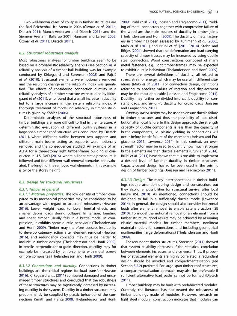
6.3.2.2 Rim beam method. Designing a rim beam is an estab-lished method of providing continuity in a light timber-framestructure and alternative load paths after element removal(Grantham and Enjily 2004; ISE 2010; Hewson 2016). A rimbeam is a continuous beam, often made of engineeredtimber, which runs on the top of internal and peripheralwalls on each storey (Hewson 2016). Edge boards of floor cas-settes may also be designed to fulfil the same purpose as a rimbeam (ISE 2010). An illustration of a rim beam is shown inFigure 10.
The rim beam is anchored to the walls below and above,and to the floor joists which may run parallel to or perpen-dicular to the rim beam (ISE 2010; Hewson 2016). The rimbeam should support the floors, and it should be able tobridge any gap after the removal of a load-bearing wallsection and transfer vertical loads to the remaining structure(Hewson 2016). In wall intersections, where two perpendicularrim beams come together, wall panels should be continuousat least 1.2m from the corner, and provide full vertical bearingof the rim beam after element removal (ISE 2010). If thissupport cannot be provided, the butt end of one rim beamshould be hung or fixed onto the crossing rim beam (ISE2010).
In the design, at least 2.4m of external wall panels and atmost 2.25H of internal wall panels should be notionallyremoved, where H is the storey height (ISE 2010). Rimbeams should support the dead load of the structure above,and one-third of the imposed loads, including the wallpanel and cladding of a single storey (ISE 2010). In addition,the rim beam should sustain horizontal tie forces as specifiedin Eurocode (ISE 2010). The rim beam, together with a wallpanel above the removed element, may act as a deep beamover gaps (Hewson 2016). The dimension and detailing ofthe rim beam may differ; for some buildings two parallel rimbeams may even be required (ISE 2010). Examples of rimbeam design details are given by ISE (2010) and Hewson(2016).
If the rim beam cannot bridge the required gap afterelement removal, additional supporting posts should bedesigned and treated as key elements (ISE 2010). Also, anytransfer beams carrying other load-bearing elements shouldin general be top-hung onto the rim beam, and designed askey elements if their failure would cause disproportionate col-lapse (ISE 2010). For key elements, Laminated Veneer Lumber(LVL) or glued laminated timber (glulam) is usually used (Arup2011).
14 J. A. J. HUBER ET AL.
As the loss of load-bearing walls over two storeys is prob-able if fire reaches the wall cavity, the notional removal ofload-bearing walls over two storeys may need to be con-sidered for certain buildings (Hewson 2016). In this case, ahigher debris load should also be considered, which may bedealt with by designing every second floor as a strong floor(Hewson 2016).
6.3.3. Post and beam construction6.3.3.1 Design in general. Post and beam constructionsconsist of continuous vertical posts and horizontal beamswhich are often pin connected to each other (Gattesco andBoem 2015). Glulam beams connected by metal connectorsand slotted-in steel plates are frequently used (Xiong andLiu 2016). Timber post and beam constructions are usuallydesigned to sustain the tie forces specified in Eurocode 1(2006), but additional checks of joint ductility and rotationcapacity should be conducted to ensure that catenaryaction can be established after column removal (Hewson2016). Connections need to yield in a ductile manner beforebrittle failure in the timber occurs. Floor slabs which remainintact after element removal may contribute to the load distri-bution after column removal (Hewson 2016). The bracingsystem for horizontal stability usually consists of diagonalmembers, timber shear walls or corresponding continuousfloor-to-roof timber walls (Gattesco and Boem 2015). Failuresin the bracing system, especially during construction, are amain reason for collapse of posts and beams (FrühwaldHansson 2011), and therefore their effects on stability needto be considered by notional element removal (Arup 2011).
Post-tensioned frames, which use tensioned steel cablesinside the beams, may be used to increase tying in timberpost and beam constructions, and enhance the developmentof catenary action after column removal (Hewson 2016). Post-tensioned frames are also able to increase moment resistanceand energy dissipation during earthquakes (Smith et al. 2016),and this might also be beneficial for robustness.
Large-span timber structures usually consist of main frames(i.e. columns and girders), secondary elements and bracing
elements (Thelandersson and Honfi 2009). To avoid collapsedue to bracing failure, it is recommended to implementmoment-resisting joints between columns and horizontalgirders (Thelandersson and Honfi 2009). For high conse-quence buildings, Thelandersson and Honfi (2009) rec-ommend that the failure of one or more elements of themain frame be considered. Large-span timber structuresshould be designed with a compartmentalisation approach(see Section 5.2.2); a weaker secondary system or fuseelements in joints (see Section 5.2.2) should isolate a failurein the main frame (Thelandersson and Honfi 2009). In thisway, a part of the structure is sacrificed so that a larger partmay survive. If, on the other hand, the failure of a maingirder must be avoided, the secondary system should bedesigned to provide alternative load paths via catenaryaction and catch the failing girder (Thelandersson and Honfi2009). Similar considerations for large-span timber structuresare presented in Dietsch and Winter (2010), Dietsch (2011)and Munch-Andersen and Dietsch (2011).
6.3.3.2 Similarities with steel frames. There are similaritiesbetween timber posts and beams and steel frames, regardingrobustness (ISE 2010; Hewson 2016). The high strength-to-weight ratio of steel is mentioned as an advantage regardingrobustness (Ellingwood et al. 2007), but timber’s strength-to-weight ratio is rather high compared to other materials, andthis should also favour timber’s behaviour under collapse. Ahigh strength-to-weight ratio also leads to a high suscepti-bility to column buckling as slender profiles can be used forstructural elements. Steel frames should be checked forcolumn buckling, if support conditions may change afterelement removal (Ellingwood et al. 2007), and this shouldalso be true for timber posts and beams.
Steel frames are usually designed to fulfil tying require-ments (Ellingwood et al. 2007; ISE 2010; Hewson 2016).Column splices along vertical ties require particular attention(ISE 2010), and this should also apply for timber posts. Steelframes are primarily designed to develop catenary action,where plastic hinges develop in the connections, and where
Figure 10. Continuous rim beams in a light timber-frame building.
WOOD MATERIAL SCIENCE & ENGINEERING 15
the full tensile capacity of the members can be utilised (Elling-wood et al. 2007; ISE 2010). Steel beams may also be designedto develop an internal plastic hinge (Ellingwood et al. 2007),which is not possible for standard timber beams due totheir brittleness. If connections with a sufficient ultimatestrength in timber posts and beams can be designed toyield in a ductile manner before brittle failure occurs in thetimber, parts of the axial capacity of timber beams could beexploited by catenary action.
In steel frames, floor slabs may develop a membrane actionafter element failure and redistribute loads, similar to floorslabs in timber posts and beams (ISE 2010; Hewson 2016).Floor diaphragms may for example be made of CLT (cross-laminated timber), which makes it possible to span in twodirections (see Figure 11). The CLT would need to be anchoredsufficiently to the framing timber structure to achieve thebeneficial effect.
Like for timber post and beam construction, the bracingsystem for horizontal stability is a critical aspect for steelframe constructions. Many collapses of steel frames arerelated to bracing failures (Frühwald et al. 2007). For a steelframe, it is therefore recommended not to rely on a singlebracing system but to implement redundant bracing (ISE2010). This additional bracing may be accomplished bymoment-resisting connections, as opposed to pinned connec-tions, by shear walls or by stair and lift cores (ISE 2010; Hewson2016). Similarly, it may be assumed that the bracing systemshould be redundant for timber posts and beams. Redun-dancy may be achieved by moment-resisting connections,shear walls of CLT (see Figure 11) or light timber-frames, ormore rigid stair and lift cores. CLT wall panels may further-more contribute to the vertical load-bearing capacity andact as deep beams, bridging over gaps.
Transfer beams support other load-bearing elementsabove them. The failure of a transfer beam in a steel frameneeds detailed consideration and may require it to bedesigned as a key element (ISE 2010; Hewson 2016). Thesame consideration should apply for timber posts andbeams. Debris loading from falling beams under collapsemay lead to increased loads in steel frames (ISE 2010), andthis may also apply for timber posts and beams, but to alower extent due to their lower weight.
6.3.4. Cross-laminated timber6.3.4.1 Design in general. Building systems based on solidwood panels, e.g. CLT floor and wall panels and stress-lami-nated timber decks, may provide a certain level of redun-dancy and ductility in a timber structure (Thelandersson andHonfi 2009). Currently, the most relevant building elementamong solid wood panels is CLT, which is made of solidwood boards, glued together in layers which are oriented per-pendicular to each other, and may support loads in plane andout of plane in perpendicular directions (Gagnon and Pirvu2011). Design guidelines for CLT buildings regarding struc-tural robustness are currently difficult to find and will beneeded in the future (Wells 2011; Bernasconi 2016; MpidiBita et al. 2017). Advantageous properties of CLT regardingrobustness may be (1) the capability to span in two directions,(2) the capability for walls to act as deep beams, and (3) the
potentially high connection capacity between CLT panels(Hewson 2016). Disadvantages may be the inherent brittle-ness of CLT (Gagnon and Pirvu 2011) and the greaterweight of panels compared to light timber-frames, whichmay lead to higher dynamic loads and increased debrisloads of falling panels.
To design a CLT building for robustness, it may be moreeconomical to apply notional element removal instead ofattempting to satisfy tie force requirements, because connec-tion loads may be lower (Hewson 2016). As noted earlier,Eurocode 1 (2006) and U.S. DoD (2016) also explain that anALPA would be the most practical choice for load-bearingwall structures of risk categories 2B and II. It seems to be gen-erally unclear how to design horizontal ties in CLT buildings(Arup 2011). To conduct an ALPA, a length of at least 2.25H(where H is the storey height) or the length of a wallbetween joints should be removed (Hewson 2016).
CLT wall panels in the storey above the removed elementmay be assumed to act as a deep beam (see Figure 12) andspan over the gap (Hewson 2016). Deep beam action mayonly be enabled if the strength capacity in the connectionsbetween the CLT walls is sufficient. CLT floors may beassumed to develop membrane action (see Section 5.2.1) ifinternal or external load-bearing walls are removed under-neath. Membrane action may only be possible if sufficientdeformation capacity and sufficient strength capacity afterdeformation exist in the connections between CLT floors,and between CLT walls and floors. The effectiveness of mem-brane action may be increased by installing double-spanningCLT floors in zigzag (staggering placement, see Figure 13) onthe walls below, to avoid a line-up of joint locations on thesupport walls (Hewson 2016).
Connections loaded in axial direction need to supply suffi-cient tension capacity and screws should therefore generallybe preferred over nails (Hewson 2016). Joint placement mayalso be decisive, e.g. to avoid buckling of a CLT panel whichacts as a deep beam after element removal (Hewson 2016).To model the response of CLT buildings after notionalelement removal, the panels may be simplified as linearsub-models, whereas nonlinear models may be applied forthe connections (Thelandersson and Honfi 2009).
6.3.4.2 Design cases. The Stadthaus in London is a nine-storey residential building designed as a platform construc-tion with CLT walls and floors. The structure was designedto sustain a notional shock load of 7.5 kPa and the removalof one wall panel or a floor panel by establishing alternativeload paths (Wells 2011). Floors and walls were connectedtogether by commonly used brackets and screws, and thefloors were designed to span in two directions and act as can-tilevers if one support was removed (Wells 2011).
Four residential buildings in Milan were designed as 9-storey platform buildings with walls and floors of CLT. Tosatisfy robustness requirements, the loss of entire wallpanels was assumed and alternative load paths weredesigned for the remaining structure (Bernasconi 2016). CLTwalls with openings and interruptions required detailed analy-sis due to the reduction in cross-section and continuity, and a
16 J. A. J. HUBER ET AL.
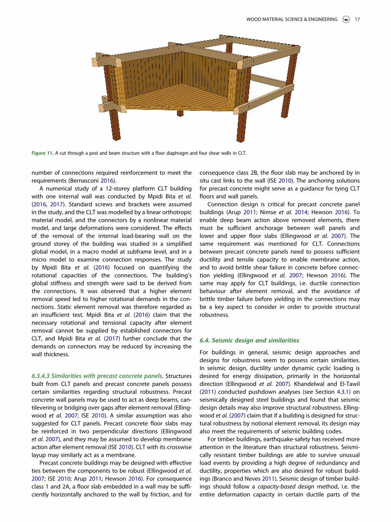
number of connections required reinforcement to meet therequirements (Bernasconi 2016).
A numerical study of a 12-storey platform CLT buildingwith one internal wall was conducted by Mpidi Bita et al.(2016, 2017). Standard screws and brackets were assumedin the study, and the CLT was modelled by a linear orthotropicmaterial model, and the connectors by a nonlinear materialmodel, and large deformations were considered. The effectsof the removal of the internal load-bearing wall on theground storey of the building was studied in a simplifiedglobal model, in a macro model at subframe level, and in amicro model to examine connection responses. The studyby Mpidi Bita et al. (2016) focused on quantifying therotational capacities of the connections. The building’sglobal stiffness and strength were said to be derived fromthe connections. It was observed that a higher elementremoval speed led to higher rotational demands in the con-nections. Static element removal was therefore regarded asan insufficient test. Mpidi Bita et al. (2016) claim that thenecessary rotational and tensional capacity after elementremoval cannot be supplied by established connectors forCLT, and Mpidi Bita et al. (2017) further conclude that thedemands on connectors may be reduced by increasing thewall thickness.
6.3.4.3 Similarities with precast concrete panels. Structuresbuilt from CLT panels and precast concrete panels possesscertain similarities regarding structural robustness. Precastconcrete wall panels may be used to act as deep beams, can-tilevering or bridging over gaps after element removal (Elling-wood et al. 2007; ISE 2010). A similar assumption was alsosuggested for CLT panels. Precast concrete floor slabs maybe reinforced in two perpendicular directions (Ellingwoodet al. 2007), and they may be assumed to develop membraneaction after element removal (ISE 2010). CLT with its crosswiselayup may similarly act as a membrane.
Precast concrete buildings may be designed with effectiveties between the components to be robust (Ellingwood et al.2007; ISE 2010; Arup 2011; Hewson 2016). For consequenceclass 1 and 2A, a floor slab embedded in a wall may be suffi-ciently horizontally anchored to the wall by friction, and for
consequence class 2B, the floor slab may be anchored by insitu cast links to the wall (ISE 2010). The anchoring solutionsfor precast concrete might serve as a guidance for tying CLTfloors and wall panels.
Connection design is critical for precast concrete panelbuildings (Arup 2011; Nimse et al. 2014; Hewson 2016). Toenable deep beam action above removed elements, theremust be sufficient anchorage between wall panels andlower and upper floor slabs (Ellingwood et al. 2007). Thesame requirement was mentioned for CLT. Connectionsbetween precast concrete panels need to possess sufficientductility and tensile capacity to enable membrane action,and to avoid brittle shear failure in concrete before connec-tion yielding (Ellingwood et al. 2007; Hewson 2016). Thesame may apply for CLT buildings, i.e. ductile connectionbehaviour after element removal, and the avoidance ofbrittle timber failure before yielding in the connections maybe a key aspect to consider in order to provide structuralrobustness.
6.4. Seismic design and similarities
For buildings in general, seismic design approaches anddesigns for robustness seem to possess certain similarities.In seismic design, ductility under dynamic cyclic loading isdesired for energy dissipation, primarily in the horizontaldirection (Ellingwood et al. 2007). Khandelwal and El-Tawil(2011) conducted pushdown analyses (see Section 4.3.1) onseismically designed steel buildings and found that seismicdesign details may also improve structural robustness. Elling-wood et al. (2007) claim that if a building is designed for struc-tural robustness by notional element removal, its design mayalso meet the requirements of seismic building codes.
For timber buildings, earthquake-safety has received moreattention in the literature than structural robustness. Seismi-cally resistant timber buildings are able to survive unusualload events by providing a high degree of redundancy andductility, properties which are also desired for robust build-ings (Branco and Neves 2011). Seismic design of timber build-ings should follow a capacity-based design method, i.e. theentire deformation capacity in certain ductile parts of the
Figure 11. A cut through a post and beam structure with a floor diaphragm and four shear walls in CLT.
WOOD MATERIAL SCIENCE & ENGINEERING 17
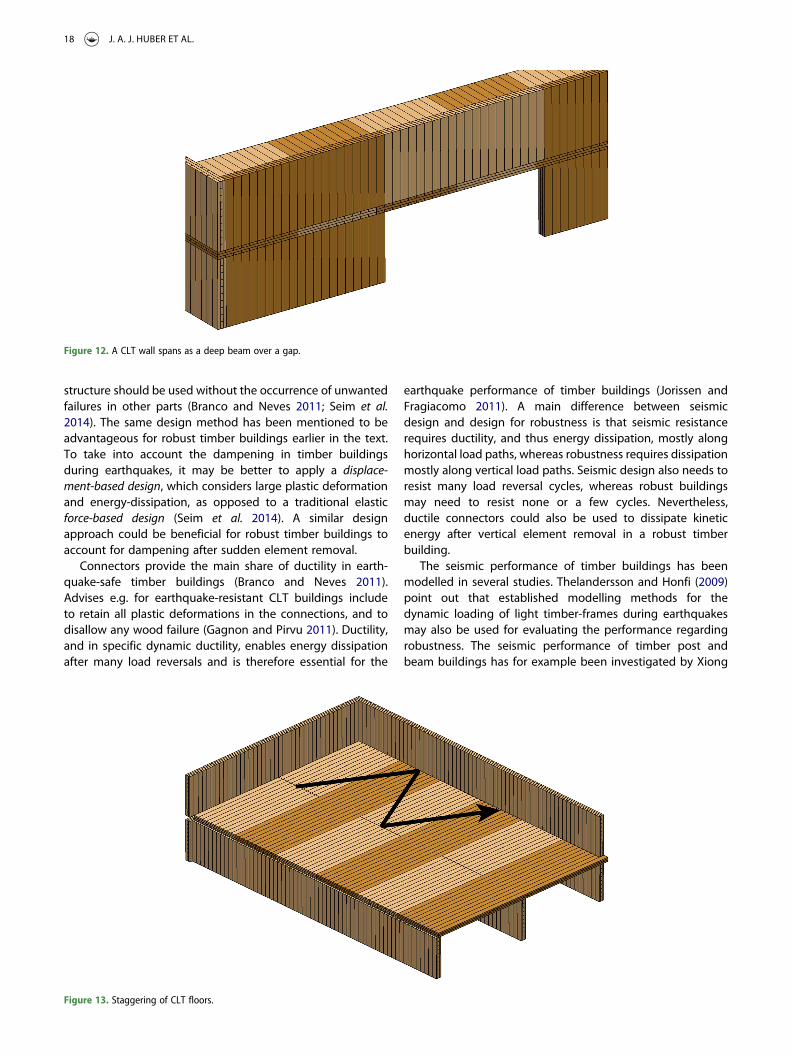
structure should be used without the occurrence of unwantedfailures in other parts (Branco and Neves 2011; Seim et al.2014). The same design method has been mentioned to beadvantageous for robust timber buildings earlier in the text.To take into account the dampening in timber buildingsduring earthquakes, it may be better to apply a displace-ment-based design, which considers large plastic deformationand energy-dissipation, as opposed to a traditional elasticforce-based design (Seim et al. 2014). A similar designapproach could be beneficial for robust timber buildings toaccount for dampening after sudden element removal.
Connectors provide the main share of ductility in earth-quake-safe timber buildings (Branco and Neves 2011).Advises e.g. for earthquake-resistant CLT buildings includeto retain all plastic deformations in the connections, and todisallow any wood failure (Gagnon and Pirvu 2011). Ductility,and in specific dynamic ductility, enables energy dissipationafter many load reversals and is therefore essential for the
earthquake performance of timber buildings (Jorissen andFragiacomo 2011). A main difference between seismicdesign and design for robustness is that seismic resistancerequires ductility, and thus energy dissipation, mostly alonghorizontal load paths, whereas robustness requires dissipationmostly along vertical load paths. Seismic design also needs toresist many load reversal cycles, whereas robust buildingsmay need to resist none or a few cycles. Nevertheless,ductile connectors could also be used to dissipate kineticenergy after vertical element removal in a robust timberbuilding.
The seismic performance of timber buildings has beenmodelled in several studies. Thelandersson and Honfi (2009)point out that established modelling methods for thedynamic loading of light timber-frames during earthquakesmay also be used for evaluating the performance regardingrobustness. The seismic performance of timber post andbeam buildings has for example been investigated by Xiong
Figure 12. A CLT wall spans as a deep beam over a gap.
Figure 13. Staggering of CLT floors.
18 J. A. J. HUBER ET AL.
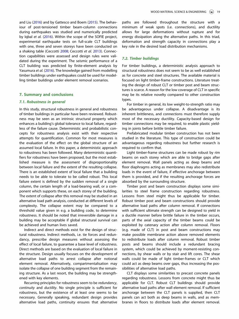
and Liu (2016) and by Gattesco and Boem (2015). The behav-iour of post-tensioned timber beam-column connectionsduring earthquakes was studied and numerically predictedby Iqbal et al. (2016). Within the scope of the SOFIE project,experimental earthquake tests on full-scale CLT buildingswith one, three and seven storeys have been conducted ona shaking table (Ceccotti 2008; Ceccotti et al. 2013). Connec-tion capabilities were assessed and design rules were vali-dated during the experiment. The seismic performance of aCLT building was predicted by finite-element analysis byYasumura et al. (2016). The knowledge gained frommodellingtimber buildings under earthquakes could be used for model-ling timber buildings under element removal scenarios.
7. Summary and conclusions
7.1. Robustness in general
In this study, structural robustness in general and robustnessof timber buildings in particular have been reviewed. Robust-ness may be seen as an intrinsic structural property whichenhances a building’s global tolerance to local failure, regard-less of the failure cause. Deterministic and probabilistic con-cepts for robustness analysis exist with their respectiveattempts for quantification. Common for most measures isthe evaluation of the effect on the global structure of anassumed local failure. In this paper, a deterministic approachto robustness has been followed. Many deterministic quanti-fiers for robustness have been proposed, but the most estab-lished measure is the assessment of disproportionalitybetween local failure and the extent of the resulting collapse.There is an established extent of local failure that a buildingneeds to be able to tolerate to be called robust. This localfailure extent is defined by the sudden removal of a singlecolumn, the certain length of a load-bearing wall, or a com-ponent which supports these, on each storey of the building.The extent of collapse after this removal may be studied in analternative load path analysis, conducted at different levels ofcomplexity. The collapse extent may be compared to athreshold value given in e.g. a building code, to determinerobustness. It should be noted that irreversible damage in abuilding may be acceptable if global structural survival canbe achieved and human lives saved.
Indirect and direct methods exist for the design of struc-tural robustness. Indirect methods, i.e. tie forces and redun-dancy, prescribe design measures without assessing theeffect of local failure, to guarantee a base level of robustness.Direct methods are based on the evaluation of local failure inthe structure. Design usually focuses on the development ofalternative load paths to arrest collapse after notionalelement removal. Alternatively, compartmentalisation mayisolate the collapse of one building segment from the remain-ing structure. As a last resort, the building may be strength-ened with key elements.
Recurring principles for robustness seem to be redundancy,continuity and ductility. No single principle is sufficient forrobustness, but the existence of at least one seems to benecessary. Generally speaking, redundant design providesalternative load paths, continuity ensures that alternative
paths are followed throughout the structure with aminimum of weak spots (i.e. connections), and ductilityallows for large deformations without rupture and forenergy dissipation along the alternative paths. In this triad,deformation and strength capacity in connections play akey role in the desired load distribution mechanisms.
7.2. Timber buildings
For timber buildings, a deterministic analysis approach tostructural robustness does not seem to be as well establishedas for concrete and steel structures. The available material isfocused on light timber-frame constructions. Literature treat-ing the design of robust CLT or timber post and beam struc-tures is scarce. A reason for the low coverage of CLT in specificmay be its relative novelty compared to other constructiontypes.
For timber in general, its low weight-to-strength ratio maybe advantageous under collapse. A disadvantage is itsinherent brittleness, and connections must therefore supplymost of the necessary ductility. Capacity-based design fortimber connections may be required, to enable plastic yield-ing in joints before brittle timber failure.
Prefabricated modular timber construction has not beenstudied in the literature. This type of construction could beadvantageous regarding robustness but further research isrequired to confirm that.
Light timber-frame structures can be made robust by rimbeams on each storey which are able to bridge gaps afterelement removal. Wall panels acting as deep beams andfloor diaphragms acting as membranes may also redistributeloads in the event of failure, if effective anchorage betweenthem is provided, and if the resulting anchorage forces areabsorbed by the surrounding structure.
Timber post and beam construction displays some simi-larities to steel frame construction regarding robustness.Lessons from steel might thus be applicable for timber.Robust timber post and beam constructions should providealternative load paths after column removal. If connectionswith sufficient ultimate strength can be designed to yield ina ductile manner before brittle failure in the timber occurs,parts of the axial capacity of the timber beams could beexploited by catenary action after column removal. Floors(e.g. made of CLT) in post and beam constructions maymake possible membrane action above removed elementsto redistribute loads after column removal. Robust timberposts and beams should include a redundant bracingsystem, which could be achieved by moment-resisting con-nections, by shear walls or by stair and lift cores. The shearwalls could be made of light timber-frames or CLT whichcould act as deep beams over gaps, thus increasing the pos-sibilities of alternative load paths.
CLT displays some similarities to precast concrete panelsregarding robustness. Lessons from concrete might thus beapplicable for CLT. Robust CLT buildings should providealternative load paths after wall element removal. If sufficientanchorage between the CLT panels is supplied, then CLTpanels can act both as deep beams in walls, and as mem-branes in floors to distribute loads after element removal.
WOOD MATERIAL SCIENCE & ENGINEERING 19
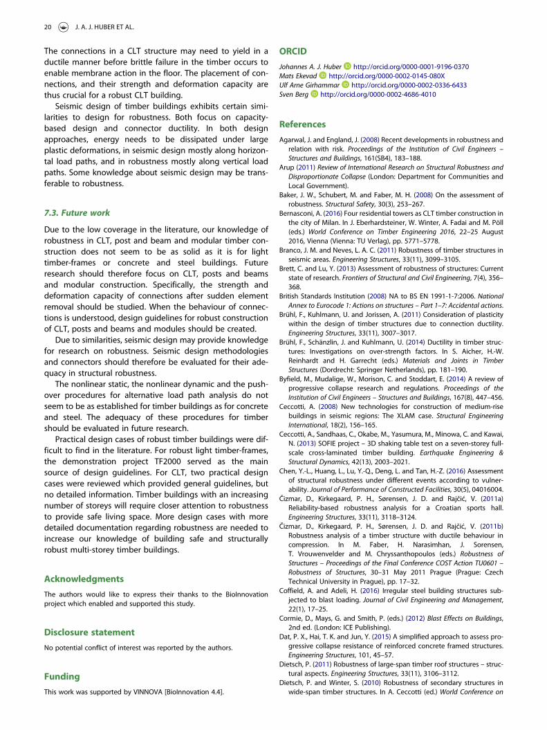
The connections in a CLT structure may need to yield in aductile manner before brittle failure in the timber occurs toenable membrane action in the floor. The placement of con-nections, and their strength and deformation capacity arethus crucial for a robust CLT building.
Seismic design of timber buildings exhibits certain simi-larities to design for robustness. Both focus on capacity-based design and connector ductility. In both designapproaches, energy needs to be dissipated under largeplastic deformations, in seismic design mostly along horizon-tal load paths, and in robustness mostly along vertical loadpaths. Some knowledge about seismic design may be trans-ferable to robustness.
7.3. Future work
Due to the low coverage in the literature, our knowledge ofrobustness in CLT, post and beam and modular timber con-struction does not seem to be as solid as it is for lighttimber-frames or concrete and steel buildings. Futureresearch should therefore focus on CLT, posts and beamsand modular construction. Specifically, the strength anddeformation capacity of connections after sudden elementremoval should be studied. When the behaviour of connec-tions is understood, design guidelines for robust constructionof CLT, posts and beams and modules should be created.
Due to similarities, seismic design may provide knowledgefor research on robustness. Seismic design methodologiesand connectors should therefore be evaluated for their ade-quacy in structural robustness.
The nonlinear static, the nonlinear dynamic and the push-over procedures for alternative load path analysis do notseem to be as established for timber buildings as for concreteand steel. The adequacy of these procedures for timbershould be evaluated in future research.
Practical design cases of robust timber buildings were dif-ficult to find in the literature. For robust light timber-frames,the demonstration project TF2000 served as the mainsource of design guidelines. For CLT, two practical designcases were reviewed which provided general guidelines, butno detailed information. Timber buildings with an increasingnumber of storeys will require closer attention to robustnessto provide safe living space. More design cases with moredetailed documentation regarding robustness are needed toincrease our knowledge of building safe and structurallyrobust multi-storey timber buildings.
Acknowledgments
The authors would like to express their thanks to the BioInnovationproject which enabled and supported this study.
Disclosure statement
No potential conflict of interest was reported by the authors.
Funding
This work was supported by VINNOVA [BioInnovation 4.4].
ORCID
Johannes A. J. Huber http://orcid.org/0000-0001-9196-0370Mats Ekevad http://orcid.org/0000-0002-0145-080XUlf Arne Girhammar http://orcid.org/0000-0002-0336-6433Sven Berg http://orcid.org/0000-0002-4686-4010
References
Agarwal, J. and England, J. (2008) Recent developments in robustness andrelation with risk. Proceedings of the Institution of Civil Engineers –Structures and Buildings, 161(SB4), 183–188.
Arup (2011) Review of International Research on Structural Robustness andDisproportionate Collapse (London: Department for Communities andLocal Government).
Baker, J. W., Schubert, M. and Faber, M. H. (2008) On the assessment ofrobustness. Structural Safety, 30(3), 253–267.
Bernasconi, A. (2016) Four residential towers as CLT timber construction inthe city of Milan. In J. Eberhardsteiner, W. Winter, A. Fadai and M. Pöll(eds.) World Conference on Timber Engineering 2016, 22–25 August2016, Vienna (Vienna: TU Verlag), pp. 5771–5778.
Branco, J. M. and Neves, L. A. C. (2011) Robustness of timber structures inseismic areas. Engineering Structures, 33(11), 3099–3105.
Brett, C. and Lu, Y. (2013) Assessment of robustness of structures: Currentstate of research. Frontiers of Structural and Civil Engineering, 7(4), 356–368.
British Standards Institution (2008) NA to BS EN 1991-1-7:2006. NationalAnnex to Eurocode 1: Actions on structures – Part 1–7: Accidental actions.
Brühl, F., Kuhlmann, U. and Jorissen, A. (2011) Consideration of plasticitywithin the design of timber structures due to connection ductility.Engineering Structures, 33(11), 3007–3017.
Brühl, F., Schänzlin, J. and Kuhlmann, U. (2014) Ductility in timber struc-tures: Investigations on over-strength factors. In S. Aicher, H.-W.Reinhardt and H. Garrecht (eds.) Materials and Joints in TimberStructures (Dordrecht: Springer Netherlands), pp. 181–190.
Byfield, M., Mudalige, W., Morison, C. and Stoddart, E. (2014) A review ofprogressive collapse research and regulations. Proceedings of theInstitution of Civil Engineers – Structures and Buildings, 167(8), 447–456.
Ceccotti, A. (2008) New technologies for construction of medium-risebuildings in seismic regions: The XLAM case. Structural EngineeringInternational, 18(2), 156–165.
Ceccotti, A., Sandhaas, C., Okabe, M., Yasumura, M., Minowa, C. and Kawai,N. (2013) SOFIE project – 3D shaking table test on a seven-storey full-scale cross-laminated timber building. Earthquake Engineering &Structural Dynamics, 42(13), 2003–2021.
Chen, Y.-L., Huang, L., Lu, Y.-Q., Deng, L. and Tan, H.-Z. (2016) Assessmentof structural robustness under different events according to vulner-ability. Journal of Performance of Constructed Facilities, 30(5), 04016004.
Čizmar, D., Kirkegaard, P. H., Sørensen, J. D. and Rajčić, V. (2011a)Reliability-based robustness analysis for a Croatian sports hall.Engineering Structures, 33(11), 3118–3124.
Čizmar, D., Kirkegaard, P. H., Sørensen, J. D. and Rajčić, V. (2011b)Robustness analysis of a timber structure with ductile behaviour incompression. In M. Faber, H. Narasimhan, J. Sorensen,T. Vrouwenvelder and M. Chryssanthopoulos (eds.) Robustness ofStructures – Proceedings of the Final Conference COST Action TU0601 –Robustness of Structures, 30–31 May 2011 Prague (Prague: CzechTechnical University in Prague), pp. 17–32.
Coffield, A. and Adeli, H. (2016) Irregular steel building structures sub-jected to blast loading. Journal of Civil Engineering and Management,22(1), 17–25.
Cormie, D., Mays, G. and Smith, P. (eds.) (2012) Blast Effects on Buildings,2nd ed. (London: ICE Publishing).
Dat, P. X., Hai, T. K. and Jun, Y. (2015) A simplified approach to assess pro-gressive collapse resistance of reinforced concrete framed structures.Engineering Structures, 101, 45–57.
Dietsch, P. (2011) Robustness of large-span timber roof structures – struc-tural aspects. Engineering Structures, 33(11), 3106–3112.
Dietsch, P. and Winter, S. (2010) Robustness of secondary structures inwide-span timber structures. In A. Ceccotti (ed.) World Conference on
20 J. A. J. HUBER ET AL.
Timber Engineering 2010, 20–24 June 2010, Riva del Garda, Italy (Rivadel Garda, Italy: Trees and Timber Institute, National ResearchCouncil), pp. 1264–1272.
Dinu, F., Dubina, D. and Marginean, I. (2015) Improving the structuralrobustness of multi-story steel-frame buildings. Structure andInfrastructure Engineering, 11(8), 1028–1041.
Ellingwood, B. R. and Dusenberry, D. O. (2005) Building design for abnor-mal loads and progressive collapse. Computer-Aided Civil andInfrastructure Engineering, 20(3), 194–205.
Ellingwood, B. R., Smilowitz, R., Dusenberry, D. O., Duthinh, D., Lew, H. S.and Carino, N. J. (2007) Best practices for reducing the potential for pro-gressive collapse in buildings (National Institute of Standards andTechnology – Technology Administration – U.S. Department ofCommerce, NISTIR 7396).
Eurocode 1 – European Committee for Standardization (2006) EN 1991-1-7:2006. Eurocode 1 – Actions on structures – Part 1-7: General actions –Accidental actions.
Frangopol, D. M. and Curley, J. P. (1987) Effects of damage and redun-dancy on structural reliability. Journal of Structural Engineering, 113(7), 1533–1549.
Frühwald, E., Serrano, E., Toratti, T., Emilsson, A. and Thelandersson, S.(2007) Design of safe timber structures – How can we learn from struc-tural failures in concrete, steel and timber? (Lund, Sweden: Division ofStructural Engineering, Lund University, TVBK-3053).
Frühwald Hansson, E. (2011) Analysis of structural failures in timber struc-tures: Typical causes for failure and failure modes. EngineeringStructures, 33(11), 2978–2982.
Gagnon, S. and Pirvu, C. (eds.) (2011) CLT Handbook: Cross-LaminatedTimber, Canadian ed. (Québec: FPInnovations).
Gattesco, N. and Boem, I. (2015) Seismic performances and behavior factorof post-and-beam timber buildings braced with nailed shear walls.Engineering Structures, 100, 674–685.
Grantham, R. and Enjily, V. (2004) UK design guidance for multi-storeytimber frame buildings. In World Conference on Timber Engineering2004, 14–17 June 2014, Lahti, Finland (Helsinki: Finnish Association ofCivil Engineers), pp. 1001–1005.
GSA – General Services Administration (2013) Alternate Path Analysis &Design Guidelines for Progressive Collapse Resistance (General ServiceAdministration), available at: https://www.gsa.gov/cdnstatic/Progressive_Collapse_2016.pdf
Hansson, M. and Larsen, H. J. (2005) Recent failures in glulam structuresand their causes. Engineering Failure Analysis, 12(5), 808–818.
Hewson, N. (2016) Robustness in Structures (Melbourne: Forest and WoodProducts Australia Limited).
ISE – The Institution of Structural Engineers (2010) Practical Guide toStructural Robustness and Disproportionate Collapse in Buildings(London: Institution of Structural Engineers).
Iqbal, A., Pampanin, S. and Buchanan, A. H. (2016) Seismic performance offull-scale post-tensioned timber beam-column connections. Journal ofEarthquake Engineering, 20(3), 383–405.
Izzuddin, B. A., Vlassis, A. G., Elghazouli, A. Y. and Nethercot, D. A. (2008)Progressive collapse of multi-storey buildings due to sudden columnloss – Part I: Simplified assessment framework. Engineering Structures,30(5), 1308–1318.
Joint Committee on Structural Safety (2001) Probabilistic model code –part 1 – basis of design. In Probabilistic Model Code (Joint Committeeon Structural Safety), available at: http://www.jcss.byg.dtu.dk/publications/probabilistic_model_code
Jorissen, A. and Fragiacomo, M. (2011) General notes on ductility in timberstructures. Engineering Structures, 33(11), 2987–2997.
Khandelwal, K. and El-Tawil, S. (2011) Pushdown resistance as a measureof robustness in progressive collapse analysis. Engineering Structures,33(9), 2653–2661.
Kirkegaard, P. H. and Sørensen, J. D. (2008) Collapse analysis of timberstructures. In B. H. V. Topping and M. Papadrakakis (eds.) Proceedingsof the Ninth International Conference on Computational StructuresTechnology, 2–5 September 2008, Athens (Stirlingshire, Scotland:Civil-Comp Press), Paper 247.
Kirkegaard, P. H., Sørensen, J. D., Čizmar, D. and Dietsch, P. (2010)Robustness evaluation of timber structures – results from EU COST
action E55:WG3. In P. J. da Sousa Cruz (ed.) Structures & Architecture:ICSA 2010 – 1st International Conference on Structures & Architecture,21–23 July 2010, Guimaraes, Portugal (CRC Press), pp. 129–131.
Kirkegaard, P. H., Sørensen, J. D., Čizmar, D. and Rajčić, V. (2011) Systemreliability of timber structures with ductile behaviour. EngineeringStructures, 33(11), 3093–3098.
Knoll, F. and Vogel, T. (2009) Design for Robustness (Zurich: InternationalAssociation for Bridge and Structural Engineering (IABSE)).
Köhler, J. (2006) Reliability of timber structures. PhD thesis. Swiss FederalInstitute of Technology.
Kokot, S. and Solomos, G. (2012) Progressive collapse risk analysis: Literaturesurvey, relevant construction standards and guidelines (Luxembourg:Publications Office of the European Union, EUR 25625 EN).
Kövecsi, T. (2014) Membrane action of slabs in framed structures in case ofaccidental column loss. MSc thesis. Politehnica University Timisoara.
Kuhlmann, U., Jaspart, J.-P., Vassart, O., Weynand, K. and Zandonini, R.(2006) Robust structure by joint ductility. In IABSE Symposium Report:Responding to Tomorrow’s Challenges in Structural Engineering,Budapest, Vol. 92 (Zurich: International Association for Bridge andStructural Engineering (IABSE)), pp. 1–8.
Kuhlmann, U., Rölle, L., Jaspart, J.-P., Demonceau, J.-F., Vassart, O.,Weynand, K., Ziller, C., Busse, E., Lendering, M., Zandonini, R. andBaldassino, N. (2009) Robust Structures by Joint Ductility (Luxembourg:Office for Official Publications of the European Communities).
Kwasniewski, L., Izzuddin, B. A., Pereira, M., Bucur, C. and Gizejowski, M. (2009)Modelling and analysis. In J. Köhler, H. Narasimhan and M. H. Faber (eds.)Proceedings of the Joint Workshop of COST Actions TU0601 and E55, 21–22September 2009, Ljubljana (Brussels: COST Office), pp. 91–102.
Lawrence, A. (2014) Recommendations for the design of complex indeter-minate timber structures. In S. Aicher, H.-W. Reinhardt and H. Garrecht(eds.) Materials and Joints in Timber Structures (Dordrecht: SpringerNetherlands), pp. 129–134.
Lawson, P. M., Byfield, M. P., Popo-Ola, S. O. and Grubb, P. J. (2008)Robustness of light steel frames and modular construction.Proceedings of the Institution of Civil Engineers - Structures andBuildings, 161(1), 3–16.
Lupoae, M. and Bucur, C. (2009) Use of applied element method tosimulate the collapse of a building. In Annual Symposium of theInstitute of Solid Mechanics SISOM 2009 and Session of the Commissionof Acoustics, 28–29 May 2009, Bucharest (Bucharest: RomanianAcademy), pp. 13–18.
Malo, K. A., Siem, J. and Ellingsbø, P. (2011) Quantifying ductility in timberstructures. Engineering Structures, 33(11), 2998–3006.
Marjanishvili, S. M. (2004) Progressive analysis procedure for progressivecollapse. Journal of Performance of Constructed Facilities, 18(2), 79–85.
Marjanishvili, S. M. and Agnew, E. (2006) Comparison of various pro-cedures for progressive collapse analysis. Journal of Performance ofConstructed Facilities, 20(4), 365–374.
Mpidi Bita, H., Currie, N. and Tannert, T. (2016) Assessment of dispropor-tionate collapse for multi- storey cross-laminated timber buildings. InJ. Eberhardsteiner, W. Winter, A. Fadai and M. Pöll (eds.) WorldConference on Timber Engineering 2016, 22–25 August 2016, Vienna(Vienna: TU Verlag), pp. 3693–3701.
Mpidi Bita, H., Currie, N. and Tannert, T. (2017) Reliability analysis and dis-proportionate collapse for multi-storey cross-laminated timber build-ing. In 16th World Conference on Earthquake Engineering (16WCEE2017), 9–13 January 2017, Santiago, Chile (Kanpur: NationalInformation Centre on Earthquake Engineering).
Munch-Andersen, J. and Dietsch, P. (2011) Robustness of large-spantimber roof structures – two examples. Engineering Structures, 33(11),3113–3117.
Nimse, R. B., Joshi, D. D. and Patel, P. V. (2014) Behavior of wet precastbeam column connections under progressive collapse scenario: Anexperimental study. International Journal of Advanced StructuralEngineering, 6(4), 149–159.
Rajčić, V., Čizmar, D., Kirkegaard, P. H. and Sørensen, J. D. (2010)Robustness analysis of timber truss structure. In A. Ceccotti (ed.)World Conference on Timber Engineering 2010, 20–24 June 2010, Rivadel Garda, Italy (Riva del Garda, Italy: Trees and Timber Institute,National Research Council), pp. 1256–1263.
WOOD MATERIAL SCIENCE & ENGINEERING 21
Sasani, M. (2008) Response of a reinforced concrete infilled-frame struc-ture to removal of two adjacent columns. Engineering Structures, 30(9), 2478–2491.
Seim, W., Hummel, J. and Vogt, T. (2014) Earthquake design of timberstructures – Remarks on force-based design procedures for differentwall systems. Engineering Structures, 76, 124–137.
Smith, J. W. (2003) Energy approach to assessing corrosion damagedstructures. Proceedings of the Institution of Civil Engineers – Structuresand Buildings, 156(2), 121–130.
Smith, I. and Frangi, A. (2008) Overview of design issues for tall timberbuildings. Structural Engineering International, 18(2), 141–147.
Smith, T., Watson, C., Moroder, D., Pampanin, S. and Buchanan, A. (2016)Lateral performance of a Pres-Lam frame designed for gravity loads.Engineering Structures, 122, 33–41.
Sørensen, J. D. (2011) Framework for robustness assessment of timberstructures. Engineering Structures, 33(11), 3087–3092.
Starossek, U. (2006) Progressive collapse of structures: nomenclature andprocedures. Structural Engineering International, 16(2), 113–117.
Starossek, U. (2007) Typology of progressive collapse. EngineeringStructures, 29(9), 2302–2307.
Starossek, U. and Haberland, M. (2010) Disproportionate collapse: termi-nology and procedures. Journal of Performance of ConstructedFacilities, 24(6), 519–528.
Starossek, U. and Haberland, M. (2011) Approaches to measures ofstructural robustness. Structure and Infrastructure Engineering, 7(7–8),625–631.
Stehn, L. and Börjes, K. (2004) The influence of nail ductility on the loadcapacity of a glulam truss structure. Engineering Structures, 26(6),809–816.
Tagel-Din, H. and Rahman, N. A. (2006) The applied element method.Structure Magazine, April 30–33.
Thelandersson, S. and Honfi, D. (2009) Behaviour and modelling of timberstructures with reference to robustness. In J. Köhler, H. Narasimhan andM. H. Faber (eds.) Proceedings of the Joint Workshop of COST ActionsTU0601 and E55, 21–22 September 2009, Ljubljana (Brussels: COSTOffice), pp. 125–138.
U.S. DoD - U.S. Department of Defense (2016) Unified Facilites Criteria (UFC)- Design of Buildings to Resist Progressive Collapse (U.S. Department ofDefense, UFC 4-023-03).
Vlassis, A. G., Izzuddin, B. A., Elghazouli, A. Y. and Nethercot, D. A. (2008)Progressive collapse of multi-storey buildings due to sudden columnloss—Part II: Application. Engineering Structures, 30(5), 1424–1438.
Wells, M. (2011) Tall timber buildings: Applications of solid timber con-struction in multistory buildings. Council on Tall Buildings and UrbanHabitat Journal, 2011(I), 24–27.
Xiong, H. and Liu, Y. (2016) Experimental study of the lateral resistance ofbolted glulam timber post and beam structural systems. Journal ofStructural Engineering, 142(4), E4014002.
Yasumura, M., Kobayashi, K., Okabe, M., Miyake, T. and Matsumoto, K.(2016) Full-scale tests and numerical analysis of low-rise CLT structuresunder lateral loading. Journal of Structural Engineering, 142(4),E4015007.
22 J. A. J. HUBER ET AL.