robustness of prototype steel frame buildings against
TRANSCRIPT
Robustness of Prototype Steel Frame Buildings against Column Loss: Assessment and Comparisons
J. A. Main1 and J. Liu2
1Engineering Laboratory, National Institute of Standards and Technology (NIST), 100 Bureau Drive, Stop 8611, Gaithersburg, MD 20899-8611; (301) 975-5286; [email protected] 2Associate Professor, Purdue University, 550 Stadium Mall Drive, West Lafayette, IN 47907-2051; (765) 494-2254; [email protected] ABSTRACT Modeling approaches for analyzing the robustness of steel moment-frame and braced frame buildings against column loss are presented, including the nonlinear behavior and failure of the shear and moment connections and the effect of the composite floor slab. For the braced-frame buildings, modeling of the buckling behavior of braces incorporates nonlinear rotational springs representing the out-of-plane behavior of the gusset-plate connections. These approaches are used to analyze the nonlinear system behavior of 10-story prototype steel moment frame and braced frame buildings under column loss scenarios. Analysis results are presented, and the behavior of braced frame and moment frame buildings under column loss is compared. INTRODUCTION As part of ongoing research on structural robustness at NIST, a number of prototype 10-story buildings have been designed for the purpose of assessing their susceptibility to disproportionate collapse. The buildings were designed in partnership with a panel of industry experts to ensure that they are representative of current design practice in the United States. Full-scale beam-column assemblies from the prototype buildings, including steel and reinforced concrete moment frames, have been tested under column removal scenarios to characterize the connection behavior and to provide experimental data for validation of detailed and reduced connection models (Sadek et al. 2011). Reduced connection models (also known as macromodels or component-based models) are assemblies of beam elements, spring elements, and rigid links that represent the nonlinear behavior and failure modes of the connections, facilitating efficient collapse analysis of large structural systems.
Full-scale tests of seismically designed steel moment connections under column removal (Lew et al. 2012) have demonstrated that these connections can develop significant vertical load-carrying capacity through a combination of flexural and catenary action, sustaining rotations almost twice as large as those observed in previous seismic tests before fracture. Reduced models of these connections have been developed (Sadek et al. 2012), and computational analyses of 10-story buildings using these reduced connection models (Main et al. 2011, Alashker et al. 2011) have shown that seismically designed moment frames can sustain the sudden loss of multiple columns without collapse. Planar analyses by Khandelwal et al. (2009)

showed that seismically designed steel braced frames could sustain the sudden loss of a column along with one or two braces without collapse.
In contrast, analyses of gravity framing systems with simple shear connections (Sadek et al. 2008, Main and Sadek 2012) have indicated a susceptibility to collapse under column loss. These studies have shown that the composite floor slab significantly enhances the capacity of the floor system relative to the bare steel framing system, but that the capacity can still be inadequate to sustain the gravity loads under sudden column loss. In analyzing a seismically designed braced frame building, Khandelwal et al. (2009) noted that gravity framing at the perimeter made the structure susceptible to progressive collapse. Khandelwal et al. (2009) performed planar analyses that did not include the floor slab but suggested that somewhat greater resistance could be expected if the floor slab were included in the analysis.
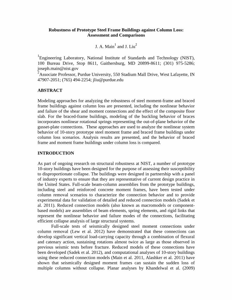
This paper presents reduced modeling approaches for assessing the robustness of steel moment-frame and braced frame buildings against column loss. The three-dimensional reduced structural models include the composite floor slab and the beam-to-column connections. For the braced-frame buildings, buckling behavior of the braces is modeled using nonlinear rotational springs at the ends of the brace members, representing the out-of-plane behavior of the gusset-plate connections. Pushdown analyses of 10-story prototype buildings under column loss scenarios are performed to assess structural robustness. The energy-based procedure suggested by Izzuddin et al. (2008), as adapted by Main and Sadek (2012), is employed to account for the dynamic effects associated with sudden column loss. PROTOTYPE STEEL FRAME BUILDINGS The prototype moment-frame and braced frame buildings considered in this paper are shown in Figure 1 and Figure 2, respectively. These two buildings were selected for comparison because the bay sizes are comparable, while it is noted that the braced frame building is 1.5 times longer in the north-south direction than the moment-frame building. Both buildings were designed for seismic design category C. Lateral loads in both buildings are resisted by seismically designed frames on the perimeter. The moment-frame building incorporates intermediate moment frames with welded unreinforced flange, bolted web (WUF-B) connections, illustrated in Figure 3(b). The braced frame building incorporates special concentrically braced frames with hollow structural section (HSS) tubes and welded gusset-plate connections, illustrated in Figure 4.
In both buildings, all interior frames were designed to support gravity loads only. Single-plate shear connections, illustrated in Figure 3(a), are used for both floor beams and girders. Details of the gravity frames and connections are indicated in Table 1. While the configuration of the gravity frames is comparable in the two buildings, it is noted that the design details differ due to differences in the span lengths. The braced frame building, with smaller spans, uses smaller diameter bolts in the connections with three bolts and also uses bolts with threads included in the shear plane. These differences result in reduced tensile capacities of the shear connections in the braced frame building relative to the moment frame building, which reduces the collapse resistance of the gravity frames, as is observed subsequently.

Figure 1. Prototype moment-frame building: (a) elevation view; (b) plan view.
Figure 2. Prototype braced frame building: (a) elevation view; (b) plan view.
Figure 3. Beam end connection details: (a) single-plate shear connection;
(b) WUF-B moment connection.
NB
5 bays @ 9.14 m
A
1
3 ba
ys @
10.
16 m
4
2
3
C D E F
intermediate moment frame
BA C D E F
5 bays @ 9.14 m
9 st
orie
s @
4.1
9 m
5.33 m
(a) (b)
NBA C D E F
1
4
2
3
V-brace and inverted V-brace5 bays @ 9.14 m
5
6
5 ba
ys @
9.1
4 m
BA C D E F
5 bays @ 9.14 m
9 st
orie
s @
4.1
9 m
5.33 m
(a) (b)
Shear tab (A36)
A325 bolts
(a)
or
Shear tab (A36)
Continuity plate (A36) A490 bolts(Class A Faying surfaces)
orColumn (A992)
CJP (Typical)
CJP
Beam (A992)
Column (A992)
Beam (A992)
(b)
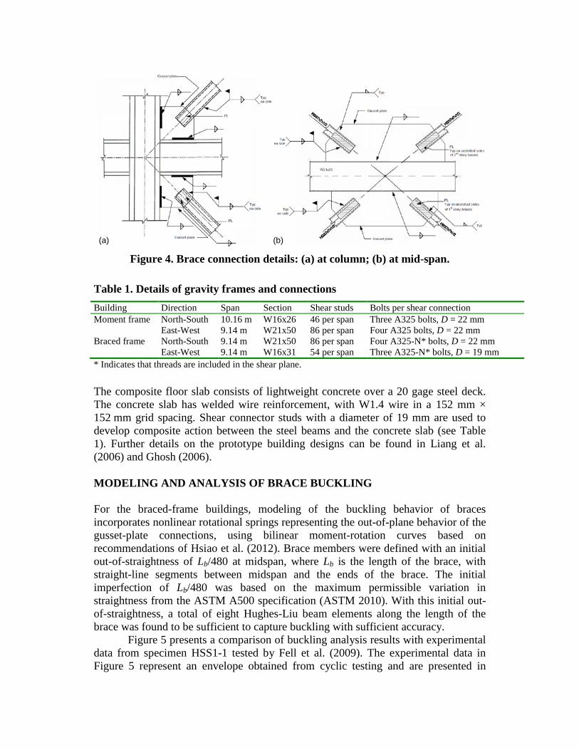
Figure 4. Brace connection details: (a) at column; (b) at mid-span.
Table 1. Details of gravity frames and connections Building Direction Span Section Shear studs Bolts per shear connection Moment frame Braced frame
North-South East-West North-South East-West
10.16 m 9.14 m 9.14 m 9.14 m
W16x26 W21x50 W21x50 W16x31
46 per span 86 per span 86 per span 54 per span
Three A325 bolts, D = 22 mm Four A325 bolts, D = 22 mm Four A325-N* bolts, D = 22 mm Three A325-N* bolts, D = 19 mm
* Indicates that threads are included in the shear plane. The composite floor slab consists of lightweight concrete over a 20 gage steel deck. The concrete slab has welded wire reinforcement, with W1.4 wire in a 152 mm × 152 mm grid spacing. Shear connector studs with a diameter of 19 mm are used to develop composite action between the steel beams and the concrete slab (see Table 1). Further details on the prototype building designs can be found in Liang et al. (2006) and Ghosh (2006). MODELING AND ANALYSIS OF BRACE BUCKLING For the braced-frame buildings, modeling of the buckling behavior of braces incorporates nonlinear rotational springs representing the out-of-plane behavior of the gusset-plate connections, using bilinear moment-rotation curves based on recommendations of Hsiao et al. (2012). Brace members were defined with an initial out-of-straightness of Lb/480 at midspan, where Lb is the length of the brace, with straight-line segments between midspan and the ends of the brace. The initial imperfection of Lb/480 was based on the maximum permissible variation in straightness from the ASTM A500 specification (ASTM 2010). With this initial out-of-straightness, a total of eight Hughes-Liu beam elements along the length of the brace was found to be sufficient to capture buckling with sufficient accuracy. Figure 5 presents a comparison of buckling analysis results with experimental data from specimen HSS1-1 tested by Fell et al. (2009). The experimental data in Figure 5 represent an envelope obtained from cyclic testing and are presented in
(a) (b)

terms of equivalent story drift for consistency with Fell et al. (2009). Analysis results are shown for two models: one in which the ends are pin-supported, and another in which springs are used to represent the gusset plate connections at the ends, following the modeling recommendations of Hsiao et al. (2012). The buckling capacity of the pin-ended model matches very closely the capacity based on the AISC specification (AISC 2010) for pinned supports, but is about 17 % less than the experimental capacity. The spring-ended model captures very closely the ultimate capacity from the experiment, as well as the general shape of the experimental compression envelope, confirming that the nonlinear rotational springs capture the additional out-of-plane stiffness provided by the gusset-plate connections.
Figure 5. Comparison of brace buckling results.
MODELING OF PROTOTYPE BUILDINGS Beam end connections. Figure 6 illustrates the reduced modeling approach used to represent the shear connections and moment connections in the prototype buildings. The primary components of the shear connection model shown in Figure 6(a) are the bolt springs, which are interconnected with rigid links to maintain the proper connection geometry. The bolt springs are implemented using a zero-length discrete beam element, with distinct load-deformation curves to represent yielding and failure (1) along the beam axis and (2) in vertical shear. Failure is represented by deleting each bolt spring from the model when its resistance drops to zero along either axis.
The yield and ultimate capacities of the bolt springs are calculated using equations in the AISC Specification (AISC 2010) with a resistance factor of φ = 1. Minimum specified values of yield strength Fy and ultimate strength Fu for each type of steel are used in these equations, and connection capacities are divided by the number of bolts to obtain the capacity of a single bolt row. Connection deformations at yield and at the ultimate load are calculated using equations in Sadek et al. (2008), which are based on data from seismic testing. While Sadek et al. (2008) considered
0
100
200
300
400
500
600
700
800
0 1 2 3
Com
pres
sive
For
ce (k
N)
Equivalent Story Drift (%)
pin-ended capacity (AISC 2010)
Compression envelope (Fell et al. 2009)
spring-ended modelpin-ended
model

axial behavior controlled by bolt tear-out and used a load-deformation with a gradual drop in resistance after the ultimate load is reached in tension, this study conservatively assumes a steeper drop in resistance after the ultimate load is reached, reflecting failures that have been observed experimentally as discussed in Main and Sadek (2012).
Because of the three-dimensional nature of composite floor systems, membrane forces in the floor slab can subject the connections to a combination of torsion and transverse shear. Accordingly, an additional discrete beam element (labeled “shear tab” in Figure 6) is used to represent the torsional and transverse shear behavior of the shear tab connection, using piecewise-linear relationships based on detailed model results (Main and Sadek 2012). The torsional and transverse shear behavior of the connection is represented by the “shear tab” element, while the in-plane axial, shear, and bending behavior is represented by the bolt springs. A “gap spring” is included at the level of the bottom flange of the beam, to allow bearing forces to be transmitted if the initial gap between the beam flange and the column closes.
The reduced model of the WUF-B moment connection shown in Figure 6(b) uses a similar approach, while additional beam elements are used to represent the beam flanges, which are welded to the columns. The shear behavior of the panel zone is represented using an arrangement of rigid links with a diagonal spring element. Further details on the modeling approach used for the shear connections and moment connections can be found in Main and Sadek (2012) and Sadek et al. (2012).
Figure 6. Reduced models: (a) shear connection; (b) moment connection.
Composite floor system. Figure 7 illustrates the reduced modeling approach used to represent the composite floor system, in which the girders, beams, and columns are represented using beam elements, and the composite floor slab is represented using shell elements. Rigid links extend vertically from the centerline of the beams and girders to the top-of-steel elevation, and elements representing shear studs connect these rigid links to nodes of the shell elements representing the floor slab.
The concrete slab on steel deck is represented in the reduced model using alternating strips of shell elements denoted “strong” and “weak” strips, which are oriented parallel to the ribs in the steel deck. The weak strips include only the concrete above the top of the steel deck, while the strong strips include the full depth of concrete and the bottom surface of the steel deck. No contribution from the steel deck is included in the weak strips, in order to represent the much lower stiffness and
column
beambolt springs
gap spring
shear tab
(a)
rigidlinks
beamflangecolumn
beam
rigid link
boltsprings
moment releases
sheartab
(b)
strength of the steel deck across the ribs than along the ribs. Six integration points are used through the thickness of each shell element, with four integration points representing the concrete, a fifth integration point representing the wire reinforcement, and a sixth integration point representing either the steel deck (for the strong strips) or a “dummy material” with negligible stiffness and strength (for the weak strips). The strips of shell elements used in this study have a width of 610 mm, about four times the average rib width. Results in Main and Sadek (2012) show that further refinement of the mesh produces little change in the computed results. Further details on the modeling approach can be found in Main and Sadek (2012), including verification with detailed model results.
Figure 7. Reduced modeling of composite floor system.
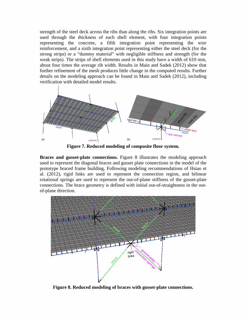
Braces and gusset-plate connections. Figure 8 illustrates the modeling approach used to represent the diagonal braces and gusset plate connections in the model of the prototype braced frame building. Following modeling recommendations of Hsiao et al. (2012), rigid links are used to represent the connection region, and bilinear rotational springs are used to represent the out-of-plane stiffness of the gusset-plate connections. The brace geometry is defined with initial out-of-straightness in the out-of-plane direction.
Figure 8. Reduced modeling of braces with gusset-plate connections.
column column(b)(a)

ROBUSTNESS ASSESSMENT AND COMPARISONS The robustness of the prototype buildings is assessed using pushdown analyses under various missing column scenarios. In the pushdown analyses, uniformly distributed gravity loading is applied to the bays adjoining the missing column and is increased gradually, maintaining quasi-static loading conditions, until global structural failure occurs, as evidenced by a drop in the resistance of the structure. The resistance is obtained by calculating both the total applied load and the corresponding total reaction force at the column bases and taking the smaller of the two values, to avoid spurious amplification of structural resistance due to dynamic effects associated with local failure (see Main and Sadek 2012). The corresponding load intensity is calculated by dividing the computed resistance by the floor area to which the pushdown loading is applied.
Bays not adjoining the missing column are loaded with a uniform service load of 1.2D + 0.5Lr, where D is the dead load and Lr is the reduced live load. This load combination is applicable for assessing residual capacity of structural systems following the notional removal of load-bearing elements, based on Section 2.5.2.2 of ASCE 7-10 (ASCE 2010). This service loading is applied gradually and is held constant, and the loads and reactions associated with this service loading are excluded from the calculation of resistance discussed above.
Figure 9 shows contours of vertical displacement at the ultimate load from pushdown analysis of the two prototype buildings with missing corner columns: column A4 in Figure 1 and column A6 in Figure 2. Corresponding load-displacement curves from the pushdown analyses are shown in Figure 10, in which the load intensity, computed from the resistance as described previously, is plotted against the vertical displacement at the location of the missing column on the first-floor level. Solid curves represent the quasi-static pushdown results, while dashed curves represent results corresponding to sudden column loss, obtained using the energy-based approximate procedure of Izzuddin et al. (2008), applied as described in Main and Sadek (2012). The dashed curve gives the peak dynamic displacement resulting from sudden column loss at a particular load intensity. Plotted for reference in Figure 9 is a dashed horizontal line corresponding to the applicable service loading of 1.2D + 0.5Lr. It is evident in Figure 10(a) that the moment-frame building, for which the corner column is part of a moment frame, can sustain the service loading even under sudden loss of the corner column. However, Figure 10(b) shows that the braced frame building, for which the corner column is part of the gravity framing system, cannot sustain loss of the corner column even under static loading.
Figure 11 shows results comparable to those in Figure 10, but for loss of penultimate columns: column B4 in Figure 1 and column B6 in Figure 2. Column B4 in Figure 1 is part of a moment frame, and the column B6 in Figure 2 is part of a braced frame. Column B6 in the braced frame is removed along with its attached brace. In both cases, the structural systems are able to sustain the applicable service loading under sudden loss of the penultimate columns. The moment frame exhibits a ductile response associated with yielding and plastic hinge formation in the beam connections, while the braced frame exhibits a stiffer response with little evidence of yielding until the ultimate load is reached, associated with out-of-plane buckling of

the braced frame system. The stiffer response of the braced frame is associated with greater dynamic amplification, as evidenced by the wider separation between the results for static loading and sudden column loss in Figure 11(a) as compared to Figure 11(b).
Figure 9. Contours of vertical displacement at ultimate load under quasi-static pushdown loading with a missing corner column: (a) moment-frame building
(column A4); (b) braced frame building (column A6).
Figure 10. Load-displacement results for corner column loss: (a) moment-frame
building (column A4); (b) braced frame building (column A6).
Figure 11. Load-displacement results for penultimate column loss: (a) moment-
frame building (column B4); (b) braced frame building (column B6).
(a) (b)
0
2
4
6
8
10
12
0 200 400 600 800 1000 1200
Uni
form
Loa
d In
tens
ity (k
N/m
2 )
Vertical Displacement at Missing Column (mm)
sudden column loss – energy-basedstatic pushdown (uniform load)
sudden column loss – direct analysis
1.2D + 0.5Lr
0
2
4
6
8
10
12
0 200 400 600 800 1000 1200
Uni
form
Loa
d In
tens
ity (k
N/m
2 )
Vertical Displacement of Center Column (mm)
sudden column loss – energy-basedstatic pushdown (uniform load)
1.2D + 0.5Lr
(a) (b)
0
2
4
6
8
10
12
0 200 400 600 800 1000 1200
Uni
form
Loa
d In
tens
ity (k
N/m
2 )
Vertical Displacement at Missing Column (mm)
0
2
4
6
8
10
12
0 10 20 30 400
2
4
6
8
10
12
0 200 400 600 800 1000 1200
Uni
form
Loa
d In
tens
ity (k
N/m
2 )
Vertical Displacement at Missing Column (mm)(a)
sudden column loss – energy-basedstatic pushdown (uniform load)
sudden column loss – direct analysis
1.2D + 0.5Lr
sudden column loss – energy-basedstatic pushdown (uniform load)
1.2D + 0.5Lr
(b)

Figure 12 shows results for loss of near-penultimate interior columns: column B3 in Figure 1 and column B5 in Figure 2. In both cases, the near-penultimate columns are part of the gravity framing systems, and Figure 12 shows that neither structure is able to sustain the service loading under near-penultimate column loss, even for static loading. The ultimate capacity is somewhat smaller for the braced frame building, due in part to the lower tensile capacity of the connections, as noted previously.
Figure 12. Load-displacement results for near-penultimate column loss: (a)
moment-frame building (column B3); (b) braced frame building (column B5). CONCLUDING REMARKS Modeling approaches for analyzing the robustness of steel moment-frame and braced frame buildings against column loss were presented, including the nonlinear behavior and failure of the shear and moment connections, the effect of the composite floor slab, and the buckling behavior of brace members. Pushdown analysis results were presented, including results corresponding to sudden column loss using an energy-based approach. The results indicated that both buildings were able to sustain sudden loss of columns that are part of the lateral load resisting system without collapse. However, both buildings were susceptible to collapse under loss of columns that are part of the gravity framing system, even under static loading.
Because of the susceptibility of gravity frames to collapse under column loss, the layout of the lateral load resisting system is an important consideration in the overall robustness of a structure. The plan layout of the moment frame building considered in this study is such that all perimeter columns are part of a moment frame, making the structure robust against loss of perimeter columns. In the braced frame building, the corner columns are part of the gravity framing system only, making the structure susceptible to collapse under corner column loss. Other plan layouts for the braced frame building could be developed in which all perimeter columns are part of a braced frame, making the structure much more robust against loss of perimeter columns.
0
2
4
6
8
10
12
0 200 400 600 800 1000 1200
Uni
form
Loa
d In
tens
ity (k
N/m
2 )
Vertical Displacement at Missing Column (mm)
1.2D + 0.5Lr
sudden column loss – energy-basedstatic pushdown (uniform load)
0
2
4
6
8
10
12
0 200 400 600 800 1000 1200U
nifo
rm L
oad
Inte
nsity
(kN
/m2 )
Vertical Displacement of Center Column (mm)
1.2D + 0.5Lr
sudden column loss – energy-basedstatic pushdown (uniform load)
(a) (b)

ACKNOWLEDGMENTS This research was supported in part by a one-year appointment of the second author as a Senior Fellow at NIST through the NIST-ARRA Fellowship Program administered by the University of Maryland. Helpful comments and input on this work from Yihai Bao, H.S. Lew, Fahim Sadek, and John Gross of NIST are gratefully acknowledged. DISCLAIMERS The policy of the National Institute of Standards and Technology is to include statements of uncertainty with all NIST measurements. In this document, however, measurements of authors outside of NIST are presented, for which uncertainties were not reported and are unknown. REFERENCES American Institute of Steel Construction (AISC). (2010). “Specification for structural
steel buildings.” ANSI/AISC 360-10, Chicago, IL. American Society of Civil Engineers (ASCE). (2010). “Minimum design loads for
buildings and other structures.” ASCE/SEI 7-10, Reston, VA. ASTM International. (2010). “Standard specification for cold-formed welded and
seamless carbon steel structural tubing in rounds and shapes.” ASTM A500/A500M-10a, West Conshohocken, PA.
Fell, B.V., Kandvinde, A.M., Deierlein, G.G., and Myers, A.T. (2009) “Experimental investigation of inelastic cyclic buckling and fracture of steel braces,” Journal of Structural Engineering, 135(1), 19-32.
Ghosh, S.K. (2006) “Assessing ability of seismic structural systems to withstand progressive collapse: design of steel braced frame buildings,” Report prepared by S.K. Ghosh & Associates, Inc., Palatine, IL.
Hsiao, P.-C., Lehman, D.E., Roeder, C.W. (2012) “Improved analytical model for special concentrically braced frames,” Journal of Constructional Steel Research, 73, 80-94.
Izzuddin, B.A., Vlassis, A.G., Elghazouli, A.Y., and Nethercot, D.A. (2008). “Progressive collapse of multi-storey buildings due to sudden column loss – Part I: Simplified assessment framework.” Engineering Structures, 30, 1308-1318.
Khandelwal, K., El-Tawil, S., Sadek, F. (2009) “Progressive collapse analysis of seismically designed steel braced frames.” Journal of Constructional Steel Research, 65, 699-708.
Lew, H.S., Main, J.A., Robert, S.D., Sadek, F., and Chiarito, V.P., (2012). “Performance of steel moment connections under a column removal scenario. I: Experiments.” Journal of Structural Engineering, 139(1), 98-107.
Liang, X., Shen, Q., Ghosh, S.K., (2006). “Assessing Ability of Seismic Structural Systems to Withstand Progressive Collapse.” Report prepared by S.K. Ghosh Associates, Inc., Palatine, IL.

Main, J.A., Bao, Y., Sadek, F., and Lew, H.S., (2011). “Experimental and computational assessment of robustness of steel and reinforced concrete framed buildings.” Proc., 11th International Conference on Applications of Statistics and Probability in Civil Engineering, Zurich, Switzerland.
Main, J.A. and Sadek, F. (2012). “Robustness of steel gravity frame systems with single-plate shear connections.” NIST Technical Note 1749, National Institute of Standards and Technology, Gaithersburg, MD.
Sadek, F., El-Tawil, S., and Lew, H.S. (2008). “Robustness of composite floor systems with shear connections: modeling, simulation, and evaluation.” Journal of Structural Engineering, 134(11), 1717-1725.
Sadek, F., Main, J.A., Lew, H.S., and Bao, Y. (2011). “Testing and analysis of steel and concrete beam-column assemblies under a column removal scenario.” Journal of Structural Engineering, 137(9), 881-892.
Sadek, F., Main, J. A., Lew, H.S., and El-Tawil, S. (2012). “Performance of steel moment connections under a column removal scenario. II: Analysis.” Journal of Structural Engineering, 139(1), 108-119.
Sadek, F., Main, J.A., Lew, H.S., Robert, S.D., Chiarito, V.P., El-Tawil, S. (2010). “An experimental and computational study of steel moment connections under a column removal scenario.” NIST Technical Note 1669, National Institute of Standards and Technology, Gaithersburg, MD.