structural analysis report - nc7j.com analysis/ustwr_hdx_572_c95r4...steel design is per the...
TRANSCRIPT
Structural Analysis Report
Structural Analysis: Self-Supporting Triangular Crank-Up Tower
Tower Model: HDX-572
IBC 2003 (TIA-222-G)
Basic Wind Velocity: 90 mph
Exposure C Ice: None
1
1
Max. Allowable Antenna Wind Load (lbs) - Unfactored: 167
Max. Allowable Antenna Weight (lbs): 300
Max. Allowable Effective Antenna Wind Area (sq. ft.): 10.8
Note: The maximum antenna values shown above include the
antenna, rotator, and any other items placed at the top of the tower.
For purposes of these calculations the antenna was placed 1 ft. above the
top of the tower.
Date Prepared: 4/1/2013 Sheet 1 of 13Prepared By: Remigio Fernandez-Garcia, P.E.
1099 W. Ropes Ave - Woodlake, CA 93285 - Ph: 559-564-6000
Topographic Cathegory:
Structure Classification:
Design Code:
THIS DOCUMENT CONTAINS PROPRIETARY INFORMATION AND SHALL NOT BE USED OR REPRODUCED OR ITS CONTENT DISCLOSED, IN WHOLE OR IN PART, WITHOUT THE PRIOR WRITTEN CONSENT OF US TOWER CORPORATION
1
11" max.
No ScalePlan View
Elevation ViewNo Scale
DIA
GO
NA
L S
IZE
LEG
SIZE
SEC
TION
NO
.
21'
72'
17'
17'
17'
4'
4'
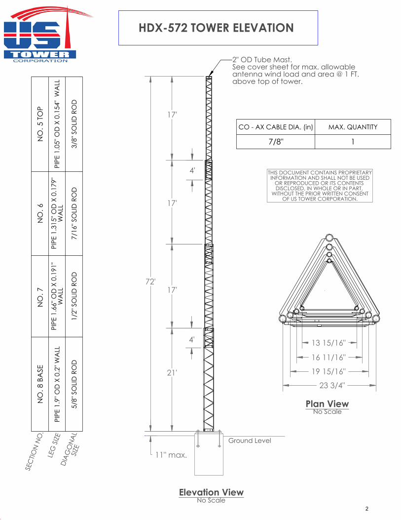
2" OD Tube Mast.See cover sheet for max. allowableantenna wind load and area @ 1 FT. above top of tower.
23 3/4"
13 15/16"
19 15/16"
16 11/16"
THIS DOCUMENT CONTAINS PROPRIETARYINFORMATION AND SHALL NOT BE USED
OR REPRODUCED OR ITS CONTENTS DISCLOSED, IN WHOLE OR IN PART,
WITHOUT THE PRIOR WRITTEN CONSENTOF US TOWER CORPORATION.
HDX-572 TOWER ELEVATION
Ground Level
NO
. 5 T
OP
PIPE
1.0
5" O
D X
0.1
54"
WA
LL
3/8"
SO
LID
RO
D
NO
. 6
PIPE
1.3
15" O
D X
0.1
79"
WA
LL
7/16
" SO
LID
RO
D
NO
. 7
PIPE
1.6
6" O
D X
0.1
91"
WA
LL
1/2"
SO
LID
RO
D
NO
. 8 B
ASE
PIPE
1.9
" OD
X 0
.2" W
ALL
5/8"
SO
LID
RO
D
CO - AX CABLE DIA. (in) MAX. QUANTITY
7/8" 1
2
General Notes:
Tower Model:
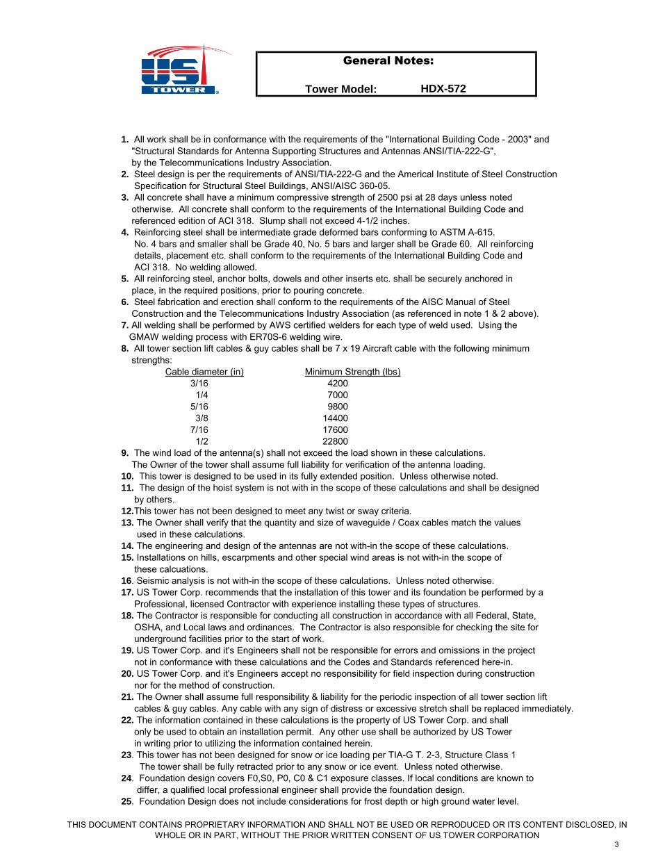
1. All work shall be in conformance with the requirements of the "International Building Code - 2003" and "Structural Standards for Antenna Supporting Structures and Antennas ANSI/TIA-222-G", by the Telecommunications Industry Association. 2. Steel design is per the requirements of ANSI/TIA-222-G and the Americal Institute of Steel Construction Specification for Structural Steel Buildings, ANSI/AISC 360-05. 3. All concrete shall have a minimum compressive strength of 2500 psi at 28 days unless noted otherwise. All concrete shall conform to the requirements of the International Building Code and referenced edition of ACI 318. Slump shall not exceed 4-1/2 inches. 4. Reinforcing steel shall be intermediate grade deformed bars conforming to ASTM A-615. No. 4 bars and smaller shall be Grade 40, No. 5 bars and larger shall be Grade 60. All reinforcing details, placement etc. shall conform to the requirements of the International Building Code and ACI 318. No welding allowed. 5. All reinforcing steel, anchor bolts, dowels and other inserts etc. shall be securely anchored in place, in the required positions, prior to pouring concrete. 6. Steel fabrication and erection shall conform to the requirements of the AISC Manual of Steel Construction and the Telecommunications Industry Association (as referenced in note 1 & 2 above). 7. All welding shall be performed by AWS certified welders for each type of weld used. Using the GMAW welding process with ER70S-6 welding wire. 8. All tower section lift cables & guy cables shall be 7 x 19 Aircraft cable with the following minimum strengths:
Cable diameter (in) Minimum Strength (lbs)3/16 42001/4 7000
5/16 98003/8 14400
7/16 176001/2 22800
9. The wind load of the antenna(s) shall not exceed the load shown in these calculations. The Owner of the tower shall assume full liability for verification of the antenna loading. 10. This tower is designed to be used in its fully extended position. Unless otherwise noted. 11. The design of the hoist system is not with in the scope of these calculations and shall be designed by others. 12.This tower has not been designed to meet any twist or sway criteria. 13. The Owner shall verify that the quantity and size of waveguide / Coax cables match the values used in these calculations. 14. The engineering and design of the antennas are not with-in the scope of these calculations. 15. Installations on hills, escarpments and other special wind areas is not with-in the scope of these calcuations. 16. Seismic analysis is not with-in the scope of these calculations. Unless noted otherwise. 17. US Tower Corp. recommends that the installation of this tower and its foundation be performed by a Professional, licensed Contractor with experience installing these types of structures. 18. The Contractor is responsible for conducting all construction in accordance with all Federal, State, OSHA, and Local laws and ordinances. The Contractor is also responsible for checking the site for underground facilities prior to the start of work. 19. US Tower Corp. and it's Engineers shall not be responsible for errors and omissions in the project not in conformance with these calculations and the Codes and Standards referenced here-in. 20. US Tower Corp. and it's Engineers accept no responsibility for field inspection during construction nor for the method of construction. 21. The Owner shall assume full responsibility & liability for the periodic inspection of all tower section lift cables & guy cables. Any cable with any sign of distress or excessive stretch shall be replaced immediately. 22. The information contained in these calculations is the property of US Tower Corp. and shall only be used to obtain an installation permit. Any other use shall be authorized by US Tower in writing prior to utilizing the information contained herein. 23. This tower has not been designed for snow or ice loading per TIA-G T. 2-3, Structure Class 1 The tower shall be fully retracted prior to any snow or ice event. Unless noted otherwise. 24. Foundation design covers F0,S0, P0, C0 & C1 exposure classes. If local conditions are known to differ, a qualified local professional engineer shall provide the foundation design. 25. Foundation Design does not include considerations for frost depth or high ground water level.
HDX-572
THIS DOCUMENT CONTAINS PROPRIETARY INFORMATION AND SHALL NOT BE USED OR REPRODUCED OR ITS CONTENT DISCLOSED, IN WHOLE OR IN PART, WITHOUT THE PRIOR WRITTEN CONSENT OF US TOWER CORPORATION
3

Code & Material Specifications
Tower Model:
Governing Codes, Stresses, and Materials (Min.)
International Building Code 2003 Edition (Occ. Cat. II)
TIA-222-G ANSI/TIA-222-G
AISC Spec for Structural Steel Bldgs ANSI/AISC 360-05
ACI 318 2008 Edition
Structural Steel ASTM A36
(All plates, bars, angles) (F-y = 36 ksi)
(Min. F-y for plates - 42 ksi)
Structural Pipe ASTM A53 Gd. B, A500 Gd. B
(F-y = 50 ksi for tower legs)
Structural Tubing (HSS) ASTM A500 Gd. B (F-y = 46 ksi)
ASTM A513 Type 1A (F-y = 42 ksi)
Welding AWS D1.1-08
GMAW w/ ER70S-6 wire per
AWS A5.18
Hot-Dip Galvanizing ASTM A123
Hardware ASTM A153
Bolts: Tower & Accessories ASTM A325
Reinforced Concrete 2500 psi strength @ 28 days
Exposure Class F0, S0, P0, C0 & C1
Reinforcing Steel ASTM A615
Gd. 40 for #4 & smaller dia.
Gd. 60 for $5 & larger dia.
Anchor Rods ASTM F1554 Gd. 36
or ASTM A-36
Foundation & Soils 1500 psf Bearing (TL = DL+LL)
Lateral Bearing Pressure 100 psf/ft of depth
HDX-572
THIS DOCUMENT CONTAINS PROPRIETARY INFORMATION AND SHALL NOT BE USED OR REPRODUCED OR ITS CONTENT DISCLOSED, IN WHOLE OR IN PART, WITHOUT THE PRIOR WRITTEN CONSENT OF US TOWER CORPORATION
4
Tower Model:
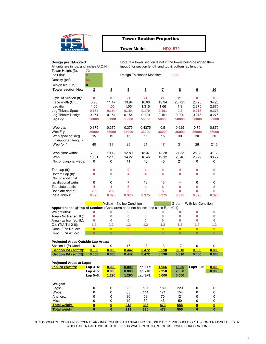
Design per TIA-222-G Note: If a tower section is not in the tower being designed thenAll units are in lbs. and inches U.O.N. input 0 for section length and top & bottom lap lengths.Tower Height (ft): 72
Ice t (in): 0 Design Thickness Modifier: 1.00
Density (pcf): 56
Design Ice t (in): 0
Tower section No.: 3 4 5 6 7 8 9 10
Lgth. of Section (ft): 0 0 21 21 21 21 0 0
Face width (C.L.): 8.95 11.47 13.94 16.68 19.94 23.725 28.25 34.25 Leg dia.: 1.05 1.05 1.05 1.315 1.66 1.9 2.375 2.875Leg Thkn's: Spec. 0.154 0.154 0.154 0.179 0.191 0.2 0.218 0.276
Leg Thkn's: Design 0.154 0.154 0.154 0.179 0.191 0.200 0.218 0.276Leg F-y: 50000 50000 50000 50000 50000 50000 50000 50000
Web dia: 0.375 0.375 0.375 0.4375 0.5 0.625 0.75 0.875Web F-y: 36000 36000 36000 36000 36000 36000 36000 36000
Web spacing: (leg 15 15 15 15 15 30 30 30 unsupported length) Web "phi": 40 31 25 21 17 31 26 21.5
Web clear width: 7.90 10.42 12.89 15.37 18.28 21.83 25.88 31.38 Web L: 10.31 12.16 14.22 16.46 19.12 25.46 28.79 33.72 No. of diagonal webs: 0 0 41 46 46 21 0 0
Top Lap (ft): 0 0 0 4 4 4 0 0
Bottom Lap (ft): 0 0 4 4 4 0 0 0
No. of additionallap diagonal webs: 0 0 7 13 13 4 0 0Top plate depth: 4 4 5 4 6 8 6 8
Bot plate depth: 2.5 2.5 3 6 5 8 8 8
Plate Thkn's: 0.375 0.375 0.375 0.375 0.375 0.375 0.375 0.375
Yellow = No Ice Condition Green = With Ice ConditionAppurtenance @ top of Section: (Coax arms need not be included since R-a <0.1)Weight (lbs): 0 0 0 0 0 0 0 0
Area - No Ice (sq. ft.): 0 0 0 0 0 0 0 0
Area - w/ Ice (sq. ft.): 0 0 0 0 0 0 0 0
C-f, (TIA Tbl 2-8): 1.2 1.2 1.2 1.2 1.2 1.2 1.2 1.2
Conc. EPA No Ice: 0 0 0 0 0 0 0 0
Conc. EPA w/ Ice: 0 0 0 0 0 0 0 0
Projected Areas Outside Lap Areas:
Section L (ft) Used: 0 0 17 13 13 17 0 0 Section PA (sqft/ft): 0.000 0.000 0.442 0.472 0.590 0.810 0.000 0.000
Section PA (sqft/ft): 0.000 0.000 0.442 0.472 0.590 0.810 0.000 0.000
Projected Areas at Laps:
Lap PA (sqft/ft): Lap 3+4: 0.000 0.000 Lap 6+7: 1.966 1.966 Lap9+10: 0.000
Lap 4+5: 0.000 0.000 Lap 7+8: 2.358 2.358 0.000
Lap 5+6: 1.290 1.290 Lap 8+9: 0.000 0.000
Weight:
Legs: 0 0 93 137 189 229 0 0 Webs: 0 0 65 114 171 154 0 0 Anchors: 0 0 36 53 70 121 0 0 Misc.: 0 0 19 30 43 50 0 0 Total weight: 0 0 213 335 473 555 0 0
Total weight: 0 0 213 335 473 555 0 0
Tower Section Properties
HDX-572
THIS DOCUMENT CONTAINS PROPRIETARY INFORMATION AND SHALL NOT BE USED OR REPRODUCED OR ITS CONTENT DISCLOSED, IN WHOLE OR IN PART, WITHOUT THE PRIOR WRITTEN CONSENT OF US TOWER CORPORATION
5

To
wer
Mo
del:
Des
ign
pe
r T
IA-2
22
-G
An
ten
na
& M
as
t /
Mo
un
t D
ata
:
Win
d ve
loci
ty (m
ph):
90
Ante
nna
Area
(ft2
):9
Mas
t Dia
. (in
):2
G-h
:0.
85G
ust f
acto
r
Expo
sure
:C
Forc
e C
oeffi
cien
t C-f:
1.2
Mas
t Lgt
h (in
):4
8I:
0.87
Impo
rtanc
e fa
ctor
Topo
Cat
egor
y:1
EPA
(ft^2
):10
.8Fo
rce
Coe
ff. C
-f:1
.2Kd
:0.
85W
ind
dire
ctio
n pr
obab
lility
fact
or
Tow
er H
eigh
t (ft)
:72
Ant.
+ M
t. w
t. (lb
s):
30
0EP
A (ft
^2):
0.80
0f:
1To
pogr
aphi
c co
effic
ient
Stru
ctur
e C
lass
if.:
1Zg
:90
0E
xpos
ure
cate
gory
coe
ffici
ent
Load
Fac
tor -
Win
d:1
.6C
o-a
x C
ab
le D
ata
:al
fa:
9.5
Exp
osur
e ca
tego
ry c
oeffi
cien
t
Load
Fac
tor -
Dea
d:1
.2C
able
dia
. (in
):0
.87
5Kz
-min
:0.
85E
xpos
ure
cate
gory
coe
ffici
ent
No.
of c
able
s:1
H (f
t):0
Ht.
of c
rest
abo
ve s
urro
undi
ng te
rrain
Ant.
Hei
ght A
bove
C-a
:1
.2Ta
ble
3 - E
IAK-
h:N
.A.
Hei
ght r
educ
tion
fact
or
Top
of T
ower
(ft):
1C
able
Pro
j. Ar
ea0.
088
(sq.
ft. /
ft.):
K-zt
:1
Topo
win
d sp
eed
up fa
ctor
K-e:
1Te
rrain
con
stan
t
Wgh
t. / C
able
(lb/
ft):
0.3
0Kt
:1
Topo
grap
hic
cons
tant
Tota
l Wgh
t (lb
):22
Win
d Ve
loci
city
Coe
ficie
ntKz
=z
> 15
'
q-z
= 0
.002
56 *
Kz *
Kzt *
Kd
* I *
G-h
* V^
2C
ontro
lling
Loa
ding
& C
ondi
tion
Tow
er
Proj
ecte
dAn
alys
isz
Kzq-
zw
(plf)
or
Shea
rM
omen
tP-
Del
taTo
tal
Def
lect
ion
Sway
Shea
rM
omen
tLi
ft C
able
Load
Sect
ion
Area
heig
ht (f
t)he
ight
(ft)
(bas
ic)
P (lb
)(lb
s)(ft
-lbs)
Mom
. (ft-
lbs)
Mom
ent
(in)
(deg
)(lb
s)(ft
-lbs)
Forc
e (lb
s)C
ondi
tion
Ante
nna
10.8
7373
1.18
418
.16
267
267
00
024
.72.
926
70
No
Ice
Mas
t0.
800
7272
.51.
183
18.1
420
287
287
028
724
.72.
928
728
7N
o Ic
eTo
p of
30.
000
7272
1.18
118
.11
028
728
70
287
24.7
2.9
3
0.00
07
272
1.18
118
.11
028
728
70
287
24.7
2.9
287
287
No
Ice
Top
of 4
0.00
072
721.
181
18.1
10
287
287
028
724
.72.
9 3
&40.
000
7272
1.18
118
.11
028
728
70
287
--
287
287
No
Ice
4
0.00
07
272
1.18
118
.11
028
728
70
287
24.7
2.9
287
287
No
Ice
Top
of 5
0.00
072
721.
181
18.1
10
287
287
028
724
.72.
9 4
&50.
000
7272
1.18
118
.11
028
728
70
287
--
287
287
No
Ice
5
0.52
95
563
.51.
150
17.6
413
502
6992
300
7292
15.1
2.5
502
7292
No
Ice
Top
of 6
0.00
055
551.
116
17.1
10
502
6992
300
7292
15.1
2.5
5&6
1.37
751
531.
107
16.9
832
630
9255
300
9556
--
630
9556
No
Ice
6
0.56
03
844
.51.
067
16.3
712
791
1849
269
119
183
7.4
1.8
791
1918
3N
o Ic
eTo
p of
70.
000
3838
1.03
215
.83
079
118
492
691
1918
37.
41.
8 6
&72.
054
3436
1.02
115
.65
4496
622
008
691
2269
9-
-96
622
699
No
Ice
7
0.67
72
127
.50.
964
14.7
914
1143
3572
110
9936
820
2.4
1.0
1143
3682
0N
o Ic
eTo
p of
80.
000
2121
0.91
113
.97
011
4335
721
1099
3682
02.
41.
0 7
&82.
446
1719
0.89
213
.68
4613
2540
658
1099
4175
7-
-13
2541
757
No
Ice
8
0.89
70
.18.
550.
850
13.0
316
1594
6532
813
7866
707
0.0
0.0
1594
6670
7N
o Ic
eTo
p of
90.
000
00
0.85
013
.03
00
00
00.
00.
0 8
&90.
088
00
0.85
013
.03
20
00
0-
-0
0Ic
e
90.
000
00
0.85
013
.03
00
00
00.
00.
00
0Ic
eTo
p of
10
0.00
00
00.
850
13.0
30
00
00
0.0
0.0
9&1
00.
000
00
0.85
013
.03
00
00
0-
-0
0Ic
e
10
0.00
00
00.
850
13.0
30
00
00
0.0
0.0
00
Ice
Not
e: T
op o
f ___
_ =
conc
entra
ted
load
app
lied
at th
e to
p of
the
tow
er s
ectio
n.
To
we
r S
ec
tio
n W
eig
hts
: (N
o Ic
e)
Lift
cabl
eSe
ctio
nW
eigh
tSe
ctio
nfo
rce
(lbs)
(lbs)
56
42
Co-
ax W
t:22
(at t
op o
f tow
er)
61
28
3
30
72
72
8
40
82
71
0
521
3N
A0
633
5N
A0
747
3N
A0
855
5N
A0
90
100
Tota
l:15
98lb
s
No
IC
E
2.01
*(z/
Zg)^
2/a
To
we
r L
oa
din
g - S
he
ar &
M
om
en
ts
Win
d L
oad
s HD
X-5
72
THIS
DO
CU
MEN
T C
ON
TAIN
S PR
OPR
IETA
RY
INFO
RM
ATIO
N A
ND
SH
ALL
NO
T BE
USE
D O
R R
EPR
OD
UC
ED O
R IT
S C
ON
TEN
T D
ISC
LOSE
D, I
N W
HO
LE O
R IN
PAR
T, W
ITH
OU
T TH
E PR
IOR
WR
ITTE
N C
ON
SEN
T O
F U
S TO
WER
CO
RPO
RAT
ION
6
To
we
r M
od
el:
De
sig
n p
er
TIA
-22
2-G
Not
e: A
ll un
its a
re in
pou
nds.
To
we
rS
ec
tio
n
Ve
rt. C
om
po
ne
nt
Se
cti
on
:W
t. (
lb):
of
Gu
y C
ab
les
(lb
):
To
we
r D
ata
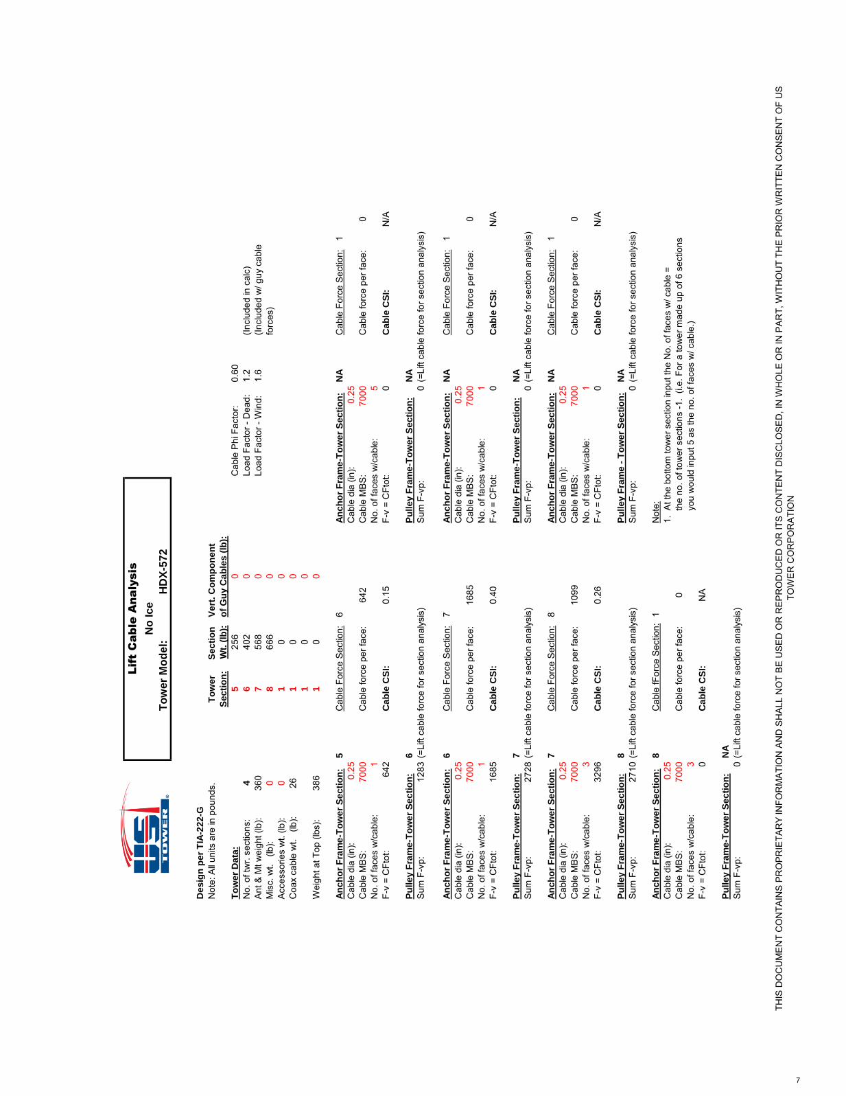
:5
256
0C
able
Phi
Fac
tor:
0.60
No.
of t
wr.
sect
ions
:4
640
20
Load
Fac
tor -
Dea
d:1.
2(In
clud
ed in
cal
c)A
nt &
Mt w
eigh
t (lb
):36
07
568
0Lo
ad F
acto
r - W
ind:
1.6
(Incl
uded
w/ g
uy c
able
Mis
c. w
t. (
lb):
08
666
0fo
rces
)A
cces
sorie
s w
t. (lb
):0
10
0C
oax
cabl
e w
t. (
lb):
261
00
10
0W
eigh
t at T
op (l
bs):
386
10
0
An
ch
or
Fra
me
-To
we
r S
ec
tio
n:
5C
able
For
ce S
ectio
n:6
An
ch
or
Fra
me
-To
we
r S
ec
tio
n:
NA
Cab
le F
orce
Sec
tion:
1C
able
dia
(in)
:0.
25C
able
dia
(in)
:0.
25C
able
MB
S:
7000
Cab
le fo
rce
per f
ace:
642
Cab
le M
BS
:70
00C
able
forc
e pe
r fac
e:0
No.
of f
aces
w/c
able
:1
No.
of f
aces
w/c
able
:5
F-v
= C
Ftot
:64
2C
ab
le C
SI:
0.15
F-v
= C
Ftot
:0
Ca
ble
CS
I:N
/A
Pu
lle
y F
ram
e-T
ow
er
Se
cti
on
:6
Pu
lle
y F
ram
e-T
ow
er
Se
cti
on
:N
A
Sum
F-v
p:12
83(=
Lift
cabl
e fo
rce
for s
ectio
n an
alys
is)
Sum
F-v
p:0
(=Li
ft ca
ble
forc
e fo
r sec
tion
anal
ysis
)
An
ch
or
Fra
me
-To
we
r S
ec
tio
n:
6C
able
For
ce S
ectio
n:7
An
ch
or
Fra
me
-To
we
r S
ec
tio
n:
NA
Cab
le F
orce
Sec
tion:
1C
able
dia
(in)
:0.
25C
able
dia
(in)
:0.
25C
able
MB
S:
7000
Cab
le fo
rce
per f
ace:
1685
Cab
le M
BS
:70
00C
able
forc
e pe
r fac
e:0
No.
of f
aces
w/c
able
:1
No.
of f
aces
w/c
able
:1
F-v
= C
Ftot
:16
85C
ab
le C
SI:
0.40
F-v
= C
Ftot
:0
Ca
ble
CS
I:N
/A
Pu
lle
y F
ram
e-T
ow
er
Se
cti
on
:7
Pu
lle
y F
ram
e-T
ow
er
Se
cti
on
:N
A
Sum
F-v
p:27
28(=
Lift
cabl
e fo
rce
for s
ectio
n an
alys
is)
Sum
F-v
p:0
(=Li
ft ca
ble
forc
e fo
r sec
tion
anal
ysis
)
An
ch
or
Fra
me
-To
we
r S
ec
tio
n:
7C
able
For
ce S
ectio
n:8
An
ch
or
Fra
me
-To
we
r S
ec
tio
n:
NA
Cab
le F
orce
Sec
tion:
1C
able
dia
(in)
:0.
25C
able
dia
(in)
:0.
25C
able
MB
S:
7000
Cab
le fo
rce
per f
ace:
1099
Cab
le M
BS
:70
00C
able
forc
e pe
r fac
e:0
No.
of f
aces
w/c
able
:3
No.
of f
aces
w/c
able
:1
F-v
= C
Ftot
:32
96C
ab
le C
SI:
0.26
F-v
= C
Ftot
:0
Ca
ble
CS
I:N
/A
Pu
lle
y F
ram
e-T
ow
er
Se
cti
on
:8
Pu
lle
y F
ram
e -
To
we
r S
ec
tio
n:
NA
Sum
F-v
p:27
10(=
Lift
cabl
e fo
rce
for s
ectio
n an
alys
is)
Sum
F-v
p:0
(=Li
ft ca
ble
forc
e fo
r sec
tion
anal
ysis
)
An
ch
or
Fra
me
-To
we
r S
ec
tio
n:
8C
able
fFor
ce S
ectio
n:1
Not
e:C
able
dia
(in)
:0.
251.
At t
he b
otto
m to
wer
sec
tion
inpu
t the
No.
of f
aces
w/ c
able
=C
able
MB
S:
7000
Cab
le fo
rce
per f
ace:
0
the
no.
of t
ower
sec
tions
-1.
(i.e.
For
a to
wer
mad
e up
of 6
sec
tions
No.
of f
aces
w/c
able
:3
y
ou w
ould
inpu
t 5 a
s th
e no
. of f
aces
w/ c
able
.)F-
v =
CFt
ot:
0C
ab
le C
SI:
NA
Pu
lle
y F
ram
e-T
ow
er
Se
cti
on
:N
A
Sum
F-v
p:0
(=Li
ft ca
ble
forc
e fo
r sec
tion
anal
ysis
)
Lift C
ab
le
A
na
lysis
No
Ic
e
HD
X-5
72
THIS
DO
CU
ME
NT
CO
NTA
INS
PR
OP
RIE
TAR
Y IN
FOR
MA
TIO
N A
ND
SH
ALL
NO
T B
E U
SE
D O
R R
EP
RO
DU
CE
D O
R IT
S C
ON
TEN
T D
ISC
LOS
ED
, IN
WH
OLE
OR
IN P
AR
T, W
ITH
OU
T TH
E P
RIO
R W
RIT
TEN
CO
NS
EN
T O
F U
S
TOW
ER
CO
RP
OR
ATI
ON
7

Tower Model:
Design per TIA-222-G
Section 3 Section 4 Section 5 Section 6 Section 7 Section 8 Section 9 Section 10
Shear (lb): 0 0 502 791 1143 1594 0 0 Lift Cable Force (lb): 0 0 642 1283 2728 2710 0 0Moment (ft-lb): 0 0 7292 19183 36820 66707 0 0 Face Width (in): 8.95 11.47 13.94 16.68 19.94 23.725 28.25 34.25Panel Height (in): 15 15 15 15 15 30 30 30Lap length (ft): 0 0 4 4 4 4 0 0Lap X Braced? Y=1, N=2 2 1 1 1 1 1 1 1
Web Analysis: Web Phi: 0.9 Weld Phi: 0.75 Weld F-exx: 70,000 psi Dia. (in): 0.375 0.375 0.375 0.4375 0.5 0.625 0.75 0.875 F-y (psi): 36000 36000 36000 36000 36000 36000 36000 36000 Area(in^2): 0.110 0.110 0.110 0.150 0.196 0.307 0.442 0.601 L (in): 10.89 12.84 14.91 17.10 19.76 26.48 29.91 34.78 r (in): 0.094 0.094 0.094 0.109 0.125 0.156 0.188 0.219L/r: 116.2 136.9 159.1 156.3 158.1 169.5 159.5 159.0 K: 0.74 0.70 0.70 0.70 0.70 0.70 0.70 0.70 KL/r: 85.8 95.9 111.4 109.4 110.6 118.6 111.7 111.3l-c: 0.96 1.08 1.25 1.23 1.24 1.33 1.25 1.25Web Force (lbs): 0 0 320 489 690 1074 0 0Ø*P-n (lbs); 2430 2206 1863 2593 3339 4738 7425 10151
Web CSI: 0.00 0.00 0.17 0.19 0.21 0.23 0.00 0.00
Effective Weld size (in): 0.141 0.141 0.141 0.164 0.188 0.234 0.281 0.32850% of Tot. Weld L (in): 0.5 0.5 0.5 0.625 0.625 0.625 0.75 0.75
Ø*F-w (lbs); 2215 2215 2215 3230 3691 4614 6645 7752Weld CSI: 0.00 0.00 0.14 0.15 0.19 0.23 0.00 0.00
Web Analysis - Lap Area Section 3 Section 4 Section 5 Section 6 Section 7 Section 8 Section 9 Section 10
Addt'l Lap shear (lbs): 0 0 1823 4796 9205 9205 0 0F-y (psi): 36000 36000 36000 36000 36000 36000 36000 36000L (in): 10.89 6.42 7.46 8.55 9.88 13.24 14.95 17.39L/r: 116.2 68.5 79.5 78.2 79.0 84.7 79.8 79.5K: 0.77 1.00 1.00 1.00 1.00 0.97 1.00 1.00KL/r 89.9 68.5 79.5 78.2 79.0 82.2 79.8 79.5l-c: 1.01 0.77 0.89 0.88 0.89 0.92 0.89 0.89Web Force (lbs): 0 0 741 1728 3124 3637 0 0Ø*P-n (lbs); 2338 2796 2565 3531 4579 6963 10241 13970
Web CSI: 0.00 0.00 0.29 0.49 0.68 0.52 0.00 0.00
Effective Weld size (in): 0.141 0.141 0.141 0.164 0.188 0.234 0.281 0.32850% of Tot. Weld L (in): 0.5 0.5 0.5 0.625 0.625 0.9375 1.125 1.125
Ø*F-w (lbs); 2215 2215 2215 3230 3691 6921 9967 11628Weld CSI: 0.00 0.00 0.33 0.53 0.85 0.53 0.00 0.00
Leg Analysis: Leg phi: 0.9
Leg Eccentricity (in): 0 0.6 1.09 1.66 2.45 0.46 1.32 1.82 Dia. (in): 1.05 1.05 1.05 1.315 1.66 1.9 2.375 2.875 Thk. (in): 0.154 0.154 0.154 0.179 0.191 0.200 0.218 0.276 F-y (psi): 50000 50000 50000 50000 50000 50000 50000 50000 Area(in^2): 0.433 0.433 0.433 0.639 0.881 1.068 1.477 2.254 r (in): 0.321 0.321 0.321 0.407 0.524 0.605 0.766 0.924D/t: 6.82 6.82 6.82 7.35 8.69 9.50 10.89 10.42F-y' for compression (psi): 50000 50000 50000 50000 50000 50000 50000 50000 K: 1.0 1.0 1.0 1.0 1.0 1.0 1.0 1.0 KL/r: 46.7 46.7 46.7 36.9 28.6 49.6 39.1 32.5l-c: 0.62 0.62 0.62 0.49 0.38 0.66 0.52 0.43Leg Comp. load (lb): 0 0 7462 16364 26497 39864 0 0ØP-n (lbs); 16636 16636 16636 26024 37357 40162 59433 93888M-u = M-ecc (in-lb): 0 0 682 2056 4475 1723 0 0ØM-n (in-lbs); 5618 5618 5618 10481 18652 26130 45798 84210
Leg CSI: 0.00 0.00 0.50 0.77 0.91 0.99 0.00 0.00
Section 3 Section 4 Section 5 Section 6 Section 7 Section 8 Section 9 Section 10
Tower Sections - Analysis
HDX-572
THIS DOCUMENT CONTAINS PROPRIETARY INFORMATION AND SHALL NOT BE USED OR REPRODUCED OR ITS CONTENT DISCLOSED, IN WHOLE OR IN PART, WITHOUT THE PRIOR WRITTEN CONSENT OF US TOWER CORPORATION
8
Tower Model:
Base Connection:
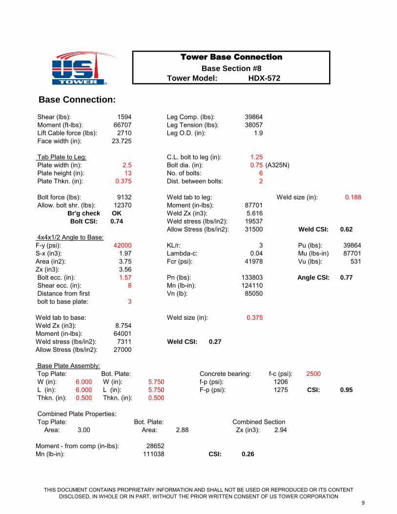
Shear (lbs): 1594 Leg Comp. (lbs): 39864 Moment (ft-lbs): 66707 Leg Tension (lbs): 38057 Lift Cable force (lbs): 2710 Leg O.D. (in): 1.9 Face width (in): 23.725
Tab Plate to Leg: C.L. bolt to leg (in): 1.25 Plate width (in): 2.5 Bolt dia. (in): 0.75 (A325N) Plate height (in): 13 No. of bolts: 6 Plate Thkn. (in): 0.375 Dist. between bolts: 2
Bolt force (lbs): 9132 Weld tab to leg: 0.188 Allow. bolt shr. (lbs): 12370 Moment (in-lbs): 87701
Br'g check OK Weld Zx (in3): 5.616Bolt CSI: 0.74 Weld stress (lbs/in2): 19537
Allow Stress (lbs/in2): 31500 Weld CSI: 0.62
4x4x1/2 Angle to Base:F-y (psi): 42000 KL/r: 3 Pu (lbs): 39864S-x (in3): 1.97 Lambda-c: 0.04 Mu (lbs-in): 87701Area (in2): 3.75 Fcr (psi): 41978 Vu (lbs): 531Zx (in3): 3.56 Bolt ecc. (in): 1.57 Pn (lbs): 133803 Angle CSI: 0.77
Shear ecc. (in): 8 Mn (lb-in): 124110 Distance from first Vn (lb): 85050 bolt to base plate: 3
Weld tab to base: Weld size (in): 0.375Weld Zx (in3): 8.754Moment (in-lbs): 64001Weld stress (lbs/in2): 7311 Weld CSI: 0.27
Allow Stress (lbs/in2): 27000
Base Plate Assembly: Top Plate: Bot. Plate: Concrete bearing: f-c (psi): 2500 W (in): 6.000 W (in): 5.750 f-p (psi): 1206 L (in): 6.000 L (in): 5.750 F-p (psi): 1275 CSI: 0.95
Thkn. (in): 0.500 Thkn. (in): 0.500
Combined Plate Properties: Top Plate: Bot. Plate: Combined Section
Area: 3.00 Area: 2.88 Zx (in3): 2.94
Moment - from comp (in-lbs): 28652Mn (lb-in): 111038 CSI: 0.26
Tower Base Connection
Base Section #8
HDX-572
Weld size (in):
THIS DOCUMENT CONTAINS PROPRIETARY INFORMATION AND SHALL NOT BE USED OR REPRODUCED OR ITS CONTENT DISCLOSED, IN WHOLE OR IN PART, WITHOUT THE PRIOR WRITTEN CONSENT OF US TOWER CORPORATION
9
Tower Model:
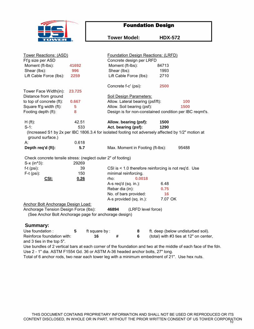
Tower Reactions: (ASD) Foundation Design Reactions: (LRFD)Ft'g size per ASD Concrete design per LRFD Moment (ft-lbs): 41692 Moment (ft-lbs): 84713 Shear (lbs): 996 Shear (lbs): 1993 Lift Cable Force (lbs): 2259 Lift Cable Force (lbs): 2710
Concrete f-c' (psi): 2500
Tower Face Width(in): 23.725
Distance from ground Soil Design Parameters:to top of concrete (ft): 0.667 Allow. Lateral bearing (psf/ft): 100
Square ft'g width (ft): 5 Allow. Soil bearing (psf): 1500
Footing depth (ft): 8 Design is for non-constained condition per IBC reqmt's.
H (ft): 42.51 Allow. bearing (psf): 1500
S-1: 533 Act. bearing (psf): 1290
(Increased S1 by 2x per IBC 1806.3.4 for isolated footing not adversely affected by 1/2" motion at ground surface.) A: 0.618 Depth req'd (ft): 5.7 Max. Moment in Footing (ft-lbs): 95488
Check concrete tensile stress: (neglect outer 2" of footing) S-x (in^3): 29269 f-t (psi): 39 CSI is < 1.0 therefore reinforcing is not req'd. Use F-t (psi): 150 minimal reinforcing.
CSI: 0.26 rho: 0.0018
A-s req'd (sq. in.): 6.48Rebar dia (in): 0.75
No. of bars provided: 16
A-s provided (sq. in.): 7.07 OKAnchor Bolt Anchorage Design Load:Anchorage Tension Design Force (lbs): 46894 (LRFD level force) (See Anchor Bolt Anchorage page for anchorage design)
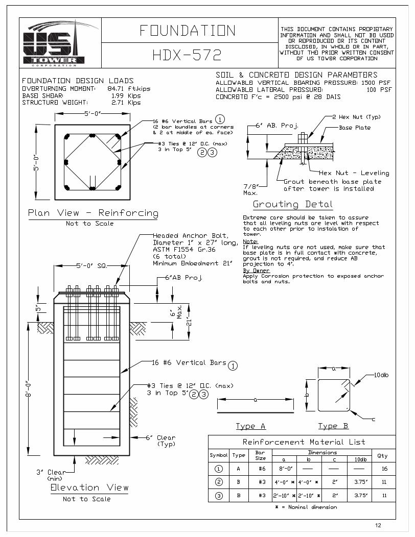
Summary:Use foundation : 5 ft square by : 8 ft. deep (below undisturbed soil).Reinforce foundation with: 16 # 6 (total) with #3 ties at 12" on center,and 3 ties in the top 5".Use bundles of 2 vertical bars at each corner of the foundation and two at the middle of each face of the fdn.Use 2 - 1" dia. ASTM F1554 Gd. 36 or ASTM A-36 headed anchor bolts, 27" long.Total of 6 anchor rods, two near each tower leg with a minimum embedment of 21". Use hex nuts.
Foundation Design
HDX-572
THIS DOCUMENT CONTAINS PROPRIETARY INFORMATION AND SHALL NOT BE USED OR REPRODUCED OR ITS CONTENT DISCLOSED, IN WHOLE OR IN PART, WITHOUT THE PRIOR WRITTEN CONSENT OF US TOWER CORPORATION
10
To
wer
Mo
del:
AC
I 318-0
8 A
pp
. D
Ten
sio
n A
nch
ora
ge C
alc
ula
tio
ns -
Cast
in P
lace S
traig
ht
An
ch
ors
All u
nits
are
pou
nds
and
inch
es u
nles
s no
ted
othe
rwis
e.
An
ch
ora
ge D
escri
pti
on
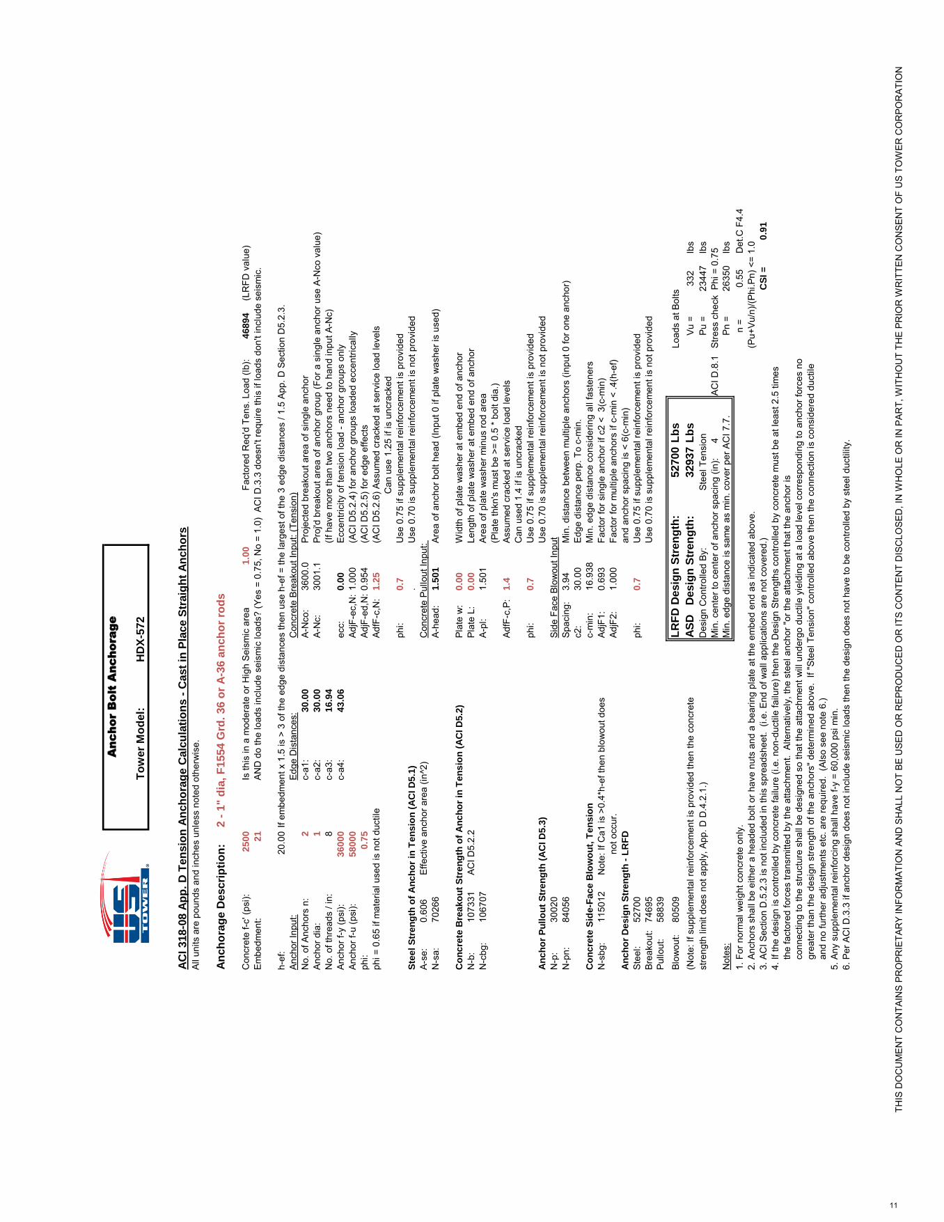
:2 -
1"
dia
, F
1554 G
rd.
36 o
r A
-36 a
nch
or
rod
s
Con
cret
e f-c
' (ps
i):2
50
0Is
this
in a
mod
erat
e or
Hig
h Se
ism
ic a
rea
1.0
0Fa
ctor
ed R
eq'd
Ten
s. L
oad
(lb):
46
89
4(L
RFD
val
ue)
Embe
dmen
t:2
1AN
D d
o th
e lo
ads
incl
ude
seis
mic
load
s? (Y
es =
0.7
5, N
o =
1.0)
AC
I D.3
.3 d
oesn
't re
quire
this
if lo
ads
don'
t inc
lude
sei
smic
.
h-ef
:20
.00
If em
bedm
ent x
1.5
is >
3 o
f the
edg
e di
stan
ces
then
use
h-e
f = th
e la
rges
t of t
he 3
edg
e di
stan
ces
/ 1.5
App
. D S
ectio
n D
5.2.
3.An
chor
Inpu
t:Ed
ge D
ista
nces
:C
oncr
ete
Brea
kout
Inpu
t: (T
ensi
on)
No.
of A
ncho
rs n
:2
c-a1
:3
0.0
0A-
Nco
:36
00.0
Proj
ecte
d br
eako
ut a
rea
of s
ingl
e an
chor
Anch
or d
ia:
1c-
a2:
30
.00
A-N
c:30
01.1
Proj
'd b
reak
out a
rea
of a
ncho
r gro
up (F
or a
sin
gle
anch
or u
se A
-Nco
val
ue)
No.
of t
hrea
ds /
in:
8c-
a3:
16
.94
(If h
ave
mor
e th
an tw
o an
chor
s ne
ed to
han
d in
put A
-Nc)
Anch
or f-
y (p
si):
36
00
0c-
a4:
43
.06
ecc:
0.0
0Ec
cent
ricity
of t
ensi
on lo
ad -
anch
or g
roup
s on
lyAn
chor
f-u
(psi
):5
80
00
AdjF
-ec,
N:
1.00
0(A
CI D
5.2.
4) fo
r anc
hor g
roup
s lo
aded
ecc
entri
cally
phi:
0.7
5Ad
jF-e
d,N
:0.9
54(A
CI D
5.2.
5) fo
r edg
e ef
fect
sph
i = 0
.65
if m
ater
ial u
sed
is n
ot d
uctil
eAd
fF-c
,N:
1.2
5(A
CI D
5.2.
6) A
ssum
ed c
rack
ed a
t ser
vice
load
leve
ls
C
an u
se 1
.25
if is
unc
rack
edph
i:0
.7U
se 0
.75
if su
pple
men
tal r
einf
orce
men
t is
prov
ided
Ste
el
Str
en
gth
of
An
ch
or
in T
en
sio
n (
AC
I D
5.1
).
Use
0.7
0 is
sup
plem
enta
l rei
nfor
cem
ent i
s no
t pro
vide
dA-
se:
0.60
6Ef
fect
ive
anch
or a
rea
(in^2
)C
oncr
ete
Pullo
ut In
put:
N-s
a:70
266
A-he
ad:
1.5
01
Area
of a
ncho
r bol
t hea
d (In
put 0
if p
late
was
her i
s us
ed)
Co
nc
rete
Bre
ak
ou
t S
tre
ng
th o
f A
nc
ho
r in
Te
ns
ion
(A
CI D
5.2
)Pl
ate
w:
0.0
0W
idth
of p
late
was
her a
t em
bed
end
of a
ncho
rN
-b:
1073
31AC
I D5.
2.2
Plat
e L:
0.0
0Le
ngth
of p
late
was
her a
t em
bed
end
of a
ncho
rN
-cbg
:10
6707
A-pl
:1.
501
Area
of p
late
was
her m
inus
rod
area
(Pla
te th
kn's
mus
t be
>= 0
.5 *
bolt
dia.
)Ad
fF-c
,P:
1.4
Assu
med
cra
cked
at s
ervi
ce lo
ad le
vels
Can
use
d 1.
4 if
is u
ncra
cked
phi:
0.7
Use
0.7
5 if
supp
lem
enta
l rei
nfor
cem
ent i
s pr
ovid
edA
nc
ho
r P
ull
ou
t S
tre
ng
th (
AC
I D
5.3
)U
se 0
.70
is s
uppl
emen
tal r
einf
orce
men
t is
not p
rovi
ded
N-p
:30
020
Side
Fac
e Bl
owou
t Inp
utN
-pn:
8405
6Sp
acin
g:3.
94M
in. d
ista
nce
betw
een
mul
tiple
anc
hors
(inp
ut 0
for o
ne a
ncho
r)c2
:30
.00
Edge
dis
tanc
e pe
rp. T
o c-
min
.C
on
cre
te S
ide
-Fa
ce
Blo
wo
ut,
Te
ns
ion
c-m
in:
16.9
38M
in. e
dge
dist
ance
con
side
ring
all f
aste
ners
N-s
bg:
1150
12N
ote:
If C
a1 is
>0.
4*h-
ef th
en b
low
out d
oes
AdjF
1:0.
693
Fact
or fo
r sin
gle
anch
or if
c2
< 3
(c-m
in)
not
occ
ur.
AdjF
2:1.
000
Fact
or fo
r mul
tiple
anc
hors
if c
-min
< .4
(h-e
f)A
nc
ho
r D
es
ign
Str
en
gth
- L
RF
Dan
d an
chor
spa
cing
is <
6(c
-min
)St
eel:
5270
0ph
i:0
.7U
se 0
.75
if su
pple
men
tal r
einf
orce
men
t is
prov
ided
Brea
kout
:74
695
Use
0.7
0 is
sup
plem
enta
l rei
nfor
cem
ent i
s no
t pro
vide
dPu
llout
:58
839
Blow
out:
8050
9L
RF
D D
esig
n S
tren
gth
:52700
Lb
sLo
ads
at B
olts
(Not
e: If
sup
plem
enta
l rei
nfor
cem
ent i
s pr
ovid
ed th
en th
e co
ncre
teA
SD
D
esig
n S
tren
gth
:32937
Lb
sVu
=33
2lb
sst
reng
th li
mit
does
not
app
ly, A
pp. D
D.4
.2.1
.)D
esig
n C
ontro
lled
By:
Stee
l Ten
sion
Pu =
2344
7lb
sM
in. c
ente
r to
cent
er o
f anc
hor s
paci
ng (i
n):
4AC
I D.8
.1St
ress
che
ck P
hi =
0.7
5N
otes
:M
in. e
dge
dist
ance
is s
ame
as m
in. c
over
per
AC
I 7.7
.Pn
=26
350
lbs
1. F
or n
orm
al w
eigh
t con
cret
e on
ly.
n =
0.55
Det
.C F
4.4
2. A
ncho
rs s
hall
be e
ither
a h
eade
d bo
lt or
hav
e nu
ts a
nd a
bea
ring
plat
e at
the
embe
d en
d as
indi
cate
d ab
ove.
(Pu+
Vu/n
)/(Ph
i.Pn)
<=
1.0
3. A
CI S
ectio
n D
.5.2
.3 is
not
incl
uded
in th
is s
prea
dshe
et.
(i.e.
End
of w
all a
pplic
atio
ns a
re n
ot c
over
ed.)
CS
I =
0.9
1
4. If
the
desi
gn is
con
trolle
d by
con
cret
e fa
ilure
(i.e
. non
-duc
tile
failu
re) t
hen
the
Des
ign
Stre
ngth
s co
ntro
lled
by c
oncr
ete
mus
t be
at le
ast 2
.5 ti
mes
th
e fa
ctor
ed fo
rces
tran
smitt
ed b
y th
e at
tach
men
t. A
ltern
ativ
ely,
the
stee
l anc
hor "
or th
e at
tach
men
t tha
t the
anc
hor i
s
con
nect
ing
to th
e st
ruct
ure
shal
l be
desi
gned
so
that
the
atta
chm
ent w
ill u
nder
go d
uctil
e yi
eldi
ng a
t a lo
ad le
vel c
orre
spon
ding
to a
ncho
r for
ces
no
gre
ater
than
the
desi
gn s
treng
th o
f the
anc
hors
" det
erm
ined
abo
ve.
If "S
teel
Ten
sion
" con
trolle
d ab
ove
then
the
conn
ectio
n is
con
side
red
duct
ile
a
nd n
o fu
rther
adj
ustm
ents
etc
. are
requ
ired.
(Al
so s
ee n
ote
6.)
5. A
ny s
uppl
emen
tal r
einf
orci
ng s
hall
have
f-y
= 60
,000
psi
min
.6.
Per
AC
I D.3
.3 if
anc
hor d
esig
n do
es n
ot in
clud
e se
ism
ic lo
ads
then
the
desi
gn d
oes
not h
ave
to b
e co
ntro
lled
by s
teel
duc
tility
.
An
ch
or B
olt A
nc
ho
ra
ge
HD
X-5
72
THIS
DO
CU
MEN
T C
ON
TAIN
S PR
OPR
IETA
RY
INFO
RM
ATIO
N A
ND
SH
ALL
NO
T BE
USE
D O
R R
EPR
OD
UC
ED O
R IT
S C
ON
TEN
T D
ISC
LOSE
D, I
N W
HO
LE O
R IN
PAR
T, W
ITH
OU
T TH
E PR
IOR
WR
ITTE
N C
ON
SEN
T O
F U
S TO
WER
CO
RPO
RAT
ION
11
12

f
13