steel beams analysis
DESCRIPTION
Steel Beam AnalysisTRANSCRIPT

Architecture 324
Structures II
Steel Beam Analysis and Design
• Steel Properties
• Steel Profiles
• Steel Codes: ASD vs LRFD
• Analysis Method
• Design Method
University of Michigan, TCAUP Structures II Slide 1/28
Cold Form Sections
University of Michigan, TCAUP Structures II Slide 2/28
Photos by Albion Sections Ltd, West Bromwich, UK

Cold Form Sections
From:
Building Design Using Cold Formed Steel Sections: Structural Design to BS 5950-5:1998. Section Properties and Load Tables. p. 276
University of Michigan, TCAUP Structures II Slide 3/28
Cold Form Sections
University of Michigan, TCAUP Structures II Slide 4/28

Hot Rolled Shapes
University of Michigan, TCAUP Structures II Slide 5/28
Hot Rolled Shapes
University of Michigan, TCAUP Structures II Slide 6/28
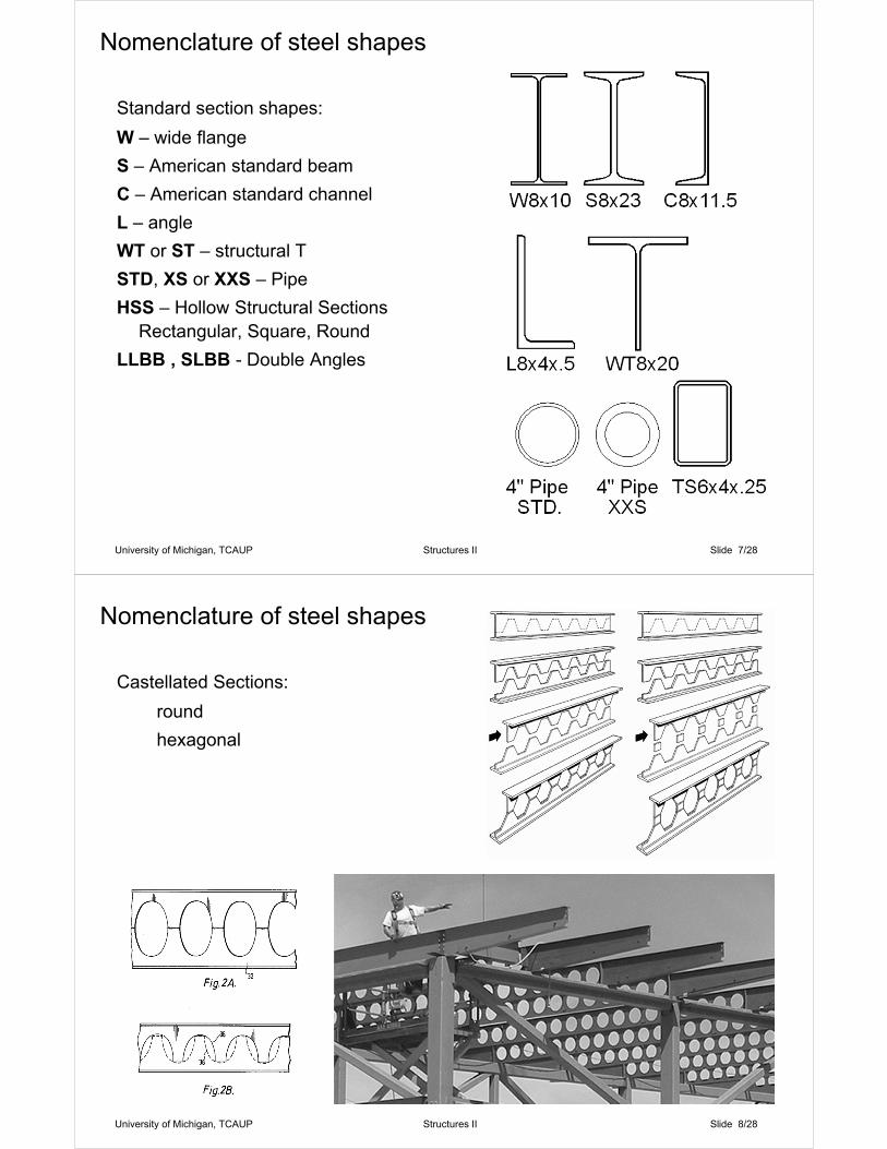
Standard section shapes:
W – wide flange
S – American standard beam
C – American standard channel
L – angle
WT or ST – structural T
STD, XS or XXS – Pipe
HSS – Hollow Structural SectionsRectangular, Square, Round
LLBB , SLBB - Double Angles
Nomenclature of steel shapes
University of Michigan, TCAUP Structures II Slide 7/28
Castellated Sections:
round
hexagonal
Nomenclature of steel shapes
University of Michigan, TCAUP Structures II Slide 8/28

Columns:
Closer to squareThicker web & flange
Beams:
Deeper sectionsFlange thicker than web
Steel W-sections for beams and columns
University of Michigan, TCAUP Structures II Slide 9/28
Columns:
Closer to squareThicker web & flange
Beams:
Deeper sectionsFlange thicker than web
Steel W-sections for beams and columns
Photo by Gregor Y.
University of Michigan, TCAUP Structures II Slide 10/28

University of Michigan, TCAUP Structures I I Slide 11/28
Young's ModulusYoung's Modulus or the Modulus of Elasticity, is obtained by dividing the stress by the strain present in the material. (Thomas Young, 1807)
It thus represents a measure of the stiffness of the material.
Strain
Stre
ss
Fu
Fy
E
y.001 to .002
u.1 to .2
sh.01 to .03
r.2 to .3
Esh
Developed by Scott CivjanUniversity of Massachusetts, Amherst
University of Michigan, TCAUP Structures I I Slide 12/28
Stress vs. Strain – mild steel

Strain
Stre
ss
E
y.001 to .002
u.1 to .2
sh.01 to .03
r.2 to .3
Esh
Elastic-Perfectly PlasticAssumed in Design
Fu
Fy
University of Michigan, TCAUP Structures I I Slide 13/28
Stress vs. Strain – AISC design curve
University of Michigan, TCAUP Structures I I Slide 14/28
Stress Analysis
Allowable Stress Design (ASD)
• use design loads (no F.S. on loads)
• reduce stress by a Factor of Safety F.S.
Load & Resistance Factored Design (LRFD)
• Use loads with safety factor
• Use factor on ultimate strength

Allowable Flexure Stress
lUniversity of Michigan, TCAUP Structures II Slide 15/28
Steel Beams by ASD
Yield Stress Values• A36 Carbon Steel Fy = 36 ksi• A992 High Strength Fy = 50 ksi
Allowable Flexure Stress• Fb = 0.66 Fy “Increased” • = Lc
– Compact Section
– Braced against LTB (l <Lc)
• Fb = 0.60 Fy “Basic” ° = Lu– Compact or Not
– Lc < l < Lu
• Fb < 0.60 Fy “Decreased”– Compact or Not
– LTB failure mode (l >Lu)
Allowable Shear Stress• Fv = 0.40 Fy
– Fv = V/(twd) lUniversity of Michigan, TCAUP Structures II Slide 16/28
from AISC 9th ed.

Given: allowable stress, steel section
Find: moment or load capacity
1. Find the Section Modulus for the given section from properties tables.
2. Determine the equation for maximum moment in the beam.
3. Assume maximum stress level: fb=Fb
4. Solve the flexure stress equation for moment: M=Fb S
5. Calculate load based on maximum moment.
Capacity Analysis of Steel Beam
University of Michigan, TCAUP Structures II Slide 17/28
Find Load w in KLFFy = 36 ksi
Fb = 0.66 Fy = 24 KSI
1. Find the Section Modulus for the given section from the tables (D-35 and D-36).
2. Determine the maximum moment equation.
Example – Capacity Analysis of Steel Beam
University of Michigan, TCAUP Structures II Slide 18/28

3. Using the flexure equation, fb=Fb, solve for the moment, M.
4. Using the maximum moment equation, solve for the distributed loading, W in kips or w in klf.
Example – Load Analysis cont.
W30x116
w = 1.28 KLF
University of Michigan, TCAUP Structures II Slide 19/28
Beam Design with Section Modulus Table1. Calculate Required Moment 2. Assume Allowable Stress
– Fully bracedFb = 0.66Fy = 24 ksi (A36)
– Partially braced (l < Lu) Fb = 0.60Fy = 21.6 ksi (A36)
3. Using the flexure equation, – set fb = Fb and solve for S
4. Choose a section based on S from the table (D-35 and D-36)
– Bold faced sections are lighter– F’y is the stress up to which the
section is compact (•• is ok for all grades of Fy)
University of Michigan, TCAUP Structures II Slide 20/28
from Structural Principles, I. Engel

1. Use the maximum moment equation, and solve for the moment, M.
2. Assume unbraced length is less than Lu therefore, Fb = 0.6 Fy = 50 ksi
3. Use the flexure equation to solve for Sx.
Design of Steel Beam
Example
University of Michigan, TCAUP Structures II Slide 21/28
4. Choose a section based on Sx = 64 in3 from the table (D35 and D36).
5. Most economical section is: W16 x 40Sx = 64.7 in3
Design of Steel Beam
Example
University of Michigan, TCAUP Structures II Slide 22/28
from Structural Principles, I. Engel

6. Add member self load to M and recheck Fb (here we assume DL is already included)
7. Check shear stress:
Allowable Stress
Fv = 0.40 Fy
Actual Stressfv=V/(twd)
fv ≤ Fv
Design of Steel Beam
Example
University of Michigan, TCAUP Structures II Slide 23/28
6. Check Deflections:
Calculate actual deflection.
Compare to code limits. If the actual deflection exceeds the code limit, a stiffer section is needed.
Design of Steel Beam(Example cont.)
University of Michigan, TCAUP Structures II Slide 24/28
from the Standard Building Code
Actual deflection
Code limits

Serviceability limits:
Limits by application
Also more stringent cases:
Machine tolerance – e.g. L/1000
DL deflection can be compensated for by beam camber
Steel Beam
Deflection
University of Michigan, TCAUP Structures II Slide 25/28
Beam without Camber
University of Michigan, TCAUP Structures II Slide 26/28
Developed by Scott CivjanUniversity of Massachusetts, AmherstFor AISC

Results in deflection in floor under Dead Load.This can affect thickness of slab and fit of non-structural components.
University of Michigan, TCAUP Structures II Slide 27/28
Developed by Scott CivjanUniversity of Massachusetts, AmherstFor AISC
Results in deflection in floor under Dead Load.This can affect thickness of slab and fit of non-structural components.
Beam with Camber
University of Michigan, TCAUP Structures II Slide 28/28
Developed by Scott CivjanUniversity of Massachusetts, AmherstFor AISC

Results in deflection in floor under Dead Load.This can affect thickness of slab and fit of non-structural components.
Cambered beam counteracts service dead load deflection.
University of Michigan, TCAUP Structures II Slide 29/28
Developed by Scott CivjanUniversity of Massachusetts, AmherstFor AISC