stress analysis at the critical points of a stabilizer … · 1,2,3 department of mechanical...
TRANSCRIPT

European International Journal of Science and Technology Vol. 4 No. 6 August, 2015
105
STRESS ANALYSIS AT THE CRITICAL POINTS OF A
STABILIZER BAR
Cristiano Antônio de Andrade1, André Chaves de Jesus2, and Claysson Bruno Santos Vimieiro3,
1,2,3
Department of Mechanical Engineering, Pontifícia Universidade Católica de Minas Gerais – PUC-MG,
Dom José GasparAv., 500 - Coração Eucarístico - Belo Horizonte - MG, Brazil
3 Department of Mechanical Engineering, Universidade Federal de Minas Gerais – UFMG,
Antônio CarlosAv., 6627 – Campus Pampulha - Belo Horizonte - MG, Brazil
Author’s Email: [email protected] 1, [email protected]
3
Corresponding Author:
Prof. Claysson Vimieiro
Department of Mechanical Engineering
Pontifícia Universidade Católica de Minas Gerais – PUC-MG
Dom José GasparAv., 500 - Coração Eucarístico - Belo Horizonte - MG, Brazil
Email: [email protected]
ABSTRACT
The present work aims to analyze the fracture of a stabilizer bar of a passenger vehicle. The goal is to
identify the structural stress on the bar and the region of fracture. The mechanical properties of the bar as
the yield strength, the ultimate strength and elongation percentage was quantified using a universal testing
machine. It was obtained the mechanical properties in tension and hardness of the bar material. The
microstructure was characterized by optical microscopy. The observed microstructures were ferrite and
pearlite. The steel used in the stabilizer bar has been classified by chemical analysis as SAE 1045. The
analytical calculation of the stresses acting at critical points of the bar was performed to check the
displacement range that the bar support without reaching the yield strength of the material. The strength
criterion used for failure analysis was the maximum distortion energy (Von Mises), due to material work
under cyclic torsion. By the Von Mises criterion, the stabilizer bar supports a stress of 503.4MPa for a
displacement of 120mm. In the region of bar fracture, it was observed the propagation of radial cracks at
the point of stress concentration towards the center of the bar. Analyzing structural stress, it is identified the
need for improvement of the fatigue resistance for the material, since for displacement up to 120mm, the
stresses calculated by the Von Mises failure criterion may cause the failure of the bar.
Key Words: Stabilizer bar, Stress, Displacement, Critical points, Vehicle.

European International Journal of Science and Technology ISSN: 2304-9693 www.eijst.org.uk
106
1 - INTRODUCTION
An automotive suspension system is one that makes the connection between the car body and wheels
designed to withstand the weight of the body and absorb the irregularities of the floor. This is an important
component in the dynamics of the vehicle, providing comfort and safety to passengers. (Bosch, 1996;
Bayrakceken, 2006).
There are several types of suspensions, however, this work will be restricted to McPherson model. This
suspension setup has the advantage of requiring little transversal space, commonly used in front suspension
of small vehicles. The McPherson suspension features are easy installation, fewer components and joints,
low weight and little sensitivity to dimensional tolerance variations (Reimpell, 1996; Santos, 1999; Bosch,
1996).
A vehicle has good maneuverability when it responds promptly to commands from the pilot safely
performing the evolutions in the various operating conditions. The dynamic behavior of a vehicle is the
result of a series of parameters such as stiffness of the springs and dampers, the sizing of the stabilizer bars
and regulation of aerodynamic appendages (Palma, 2002; He, 2010).
The stabilizer bar is one of the components of the suspension system that aims to contribute to the safety and
dynamic stability of vehicles especially when traveling at high speeds and curvilinear trajectories. They can
be manufactured of solid or tubular steel bars with the aim of reducing the angle of inclination of the body
vehicle (Bosch, 1996).
Shafts suffer two types of damage: cracking and wear. The crash is caused by overloading or fatigue. The
overload is the result of work done beyond the carrying capacity of the shaft, while fatigue is the loss of
resistance exerted by the material of the shaft, due the demands over time. (Van Vlack, 1984; Beer, 1995;
Cerit, 2010).
Steps and rebounds are usually used to provide a precise axial location of shafts, as well as to create an
appropriate diameter to accommodate standard parts such as bearings. Wedges, retaining rings and pins are
used for fastening elements attached to the axle in order to transmit the required torque. Each shaft section
change contributes to the onset of stress concentration. Points with stress concentration should be considered
in designing a mechanical component (Bonora, 1997; Hibbeler, 2000).
The aim of the present work is to calculate the stresses acting at critical points of a stabilizer bar of a
passenger vehicle, to check the displacement range that the bar support without reaching the yield strength
of the material. The strength criterion used for failure analysis was the maximum distortion energy (Von
Mises), due to material work under cyclic torsion.
2 - METHODS
2.1 - Preliminary analysis of working conditions
Before starting the analysis of the failure of stabilizer bar, the bar working conditions has been analyzed. It
is observed that the bar is subjected to thermal shock from the heat generated by the engine, the airflow
incident and exposure to liquids of the track. Furthermore, the bar supports a load and a torsion caused by
the suspension system. Figures 1 and 2 show the stabilizer bar studied here.

European International Journal of Science and Technology Vol. 4 No. 6 August, 2015
Figure 1 - Stabilizer bar – Top view
Figure 2 - Rupture bar section
A chemical analysis was performed for classification of steel used in manufacturing the stabilizer bar. The
mechanical properties of the material were quantified using a universal testing machine (tensile test). It was
used one test sample to obtain the values of the yield strength and ultimate strength of the material.
The metallographic characterization of microstructure and surface condition of the bar after the failure were
evaluated in an optical microscope. The image was magnified 100x and 250x. It was performed a hardness
test on 10 samples using a micro hardness (ABNT, 1996).
It was calculated the stresses acting at critical point of a stabilizer bar, to check the displacement range that
the bar support without reaching the yield strength of the material. The strength criterion used for failure
analysis was the maximum distortion energy (Von Mises), due to material work under cyclic torsion.
2.2 - Criterion of maximum distortion energy (Von Mises)
This criterion suggests that the flow-through failure is associated with critical values of strain energy from
the point under study. When the principal stresses have different values, the cube that represents the point
turns to cobblestone (Hibbeler, 2000; Wulpi, 1999). The energy for this distortion is given by Eq. 1:
( ) ( ) ( )[ ]2
32
2
31
2
21*6
1σσσσσσ
ν−+−+−
+=
EU
(1)
Stress
Concentration
Region
European International Journal of Science and Technology ISSN: 2304-9693 www.eijst.org.uk
108
where (E) is the elasticity modulus of the material and (ν) is the coefficient of Poison. The same occurs for
the equivalent stress in this situation since σ1=σeq andσ2=σ3=0. For the equivalent stress, the distortion
energy is (Eq. 2):
2*2*
*6
1eq
EU σ
ν+=
(2)
Combining the Eq.1 and Eq.2:
( ) ( ) ( ) 22
32
2
31
2
21 *2 eqσσσσσσσ =−+−+− (3)
and:
( ) ( ) ( )[ ]2
32
2
31
2
21)(2
1σσσσσσσ −+−+−=VonMiseseq
(4)
The criterion also considers the ductility of the material used and the yield strength and failure stress, and
applied only for ductile materials (Souza, 1984; Bonora, 1997).
3 - RESULTS
The steel used in manufacturing the stabilizer bar has been classified by chemical analysis as SAE 1045,
having 0.45% of carbon and 0.64% of manganese (ASM, 1995; ABNT, 1996). The material shows the
presence of the elements listed in table 1.
Table 1 – Stabilizer bar chemical composition
Chemical
Composition C Si Mn Cr Ni Co Cu Ti
Average Percent 0.448 0.217 0.637 0.335 0.159 0.005 0.040 0.002
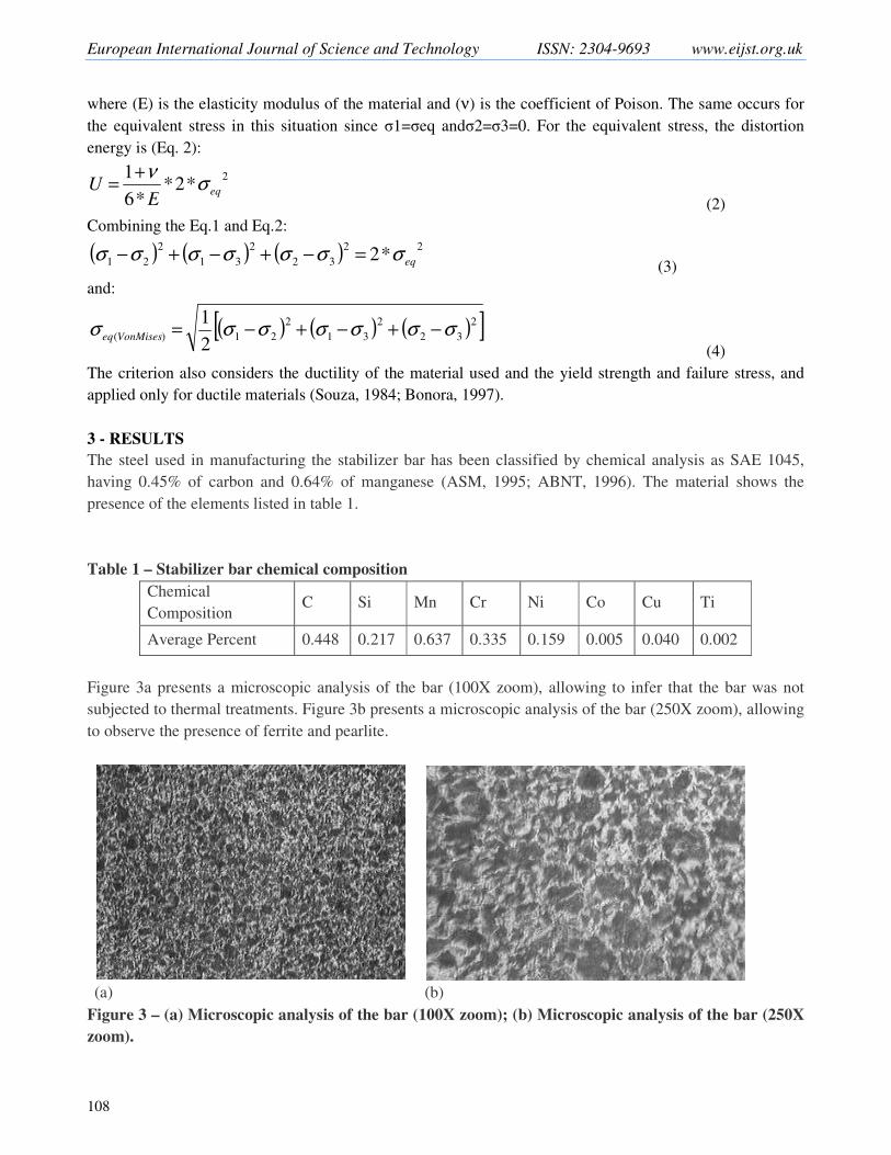
Figure 3a presents a microscopic analysis of the bar (100X zoom), allowing to infer that the bar was not
subjected to thermal treatments. Figure 3b presents a microscopic analysis of the bar (250X zoom), allowing
to observe the presence of ferrite and pearlite.
(a) (b)
Figure 3 – (a) Microscopic analysis of the bar (100X zoom); (b) Microscopic analysis of the bar (250X
zoom).

European International Journal of Science and Technology Vol. 4 No. 6 August, 2015
109
The hardness test were performed on 15 samples taken from: (a) the fractured stabilizer bar; (b) an used
stabilizer bar, but that did not suffer fracture; (c) a new stabilizer bar. Samples were taken diametrically in
cross section and the values obtained are shown in Table 2, obtaining an average Rockwell hardness of 15
HRC.
Table 2 - Rockwell hardness values obtained in tests.
Durometer: Rockwell Diamond Brale
Sample number Load Minimum hardness Maximum
hardness
Average
hardness
(a) 150 kgf 15HRC 17HRC 15HRC
(b) 150 kgf 15HRC 17HRC 16HRC
(c) 150 kgf 15HRC 16HRC 15HRC
It was noted that the fracture occurred in the curvature radius immediately after the fixation point of the
stabilizer bar. Moreover, it was observed that there is a notch enhancing the stress concentration in the
failure region. This notch occurs on both sides of the bar, being result of the folding process used.
The values of the yield strength and the ultimate strength of the material were obtained in the tensile test
(Table 3).
Table 3 - Yield strength and the ultimate strength of the material obtained in the tensile test.
Diameter (mm) Yield strength (MPa)
Ultimate strength
(MPa) Elongation (%)
Initial End
9.85 6.03 335.4 619 17
3.1 - Stress Analytical Calculation
The geometrical and mechanical properties of the stabilizer bar are shown below. (ABNT, 2002; Castro,
2010). For the material SAE 1045, the Elasticity modulus (E) is 205 GPa and the Coefficient of Poison (v) is
0.28. The elasticity modulus (G) and the moments of inertia (I) and (J) were calculated as follows:
� = ��(���) = ��∗� [��]
�(��.��) = 80[���] (4)
� = ����� = �(.�)�
�� = 4.91 ∗ 10!�["�] (5)
# = �(�)�$� = �(.�)�
$� = 9.28 ∗ 10!�["�] (6)
The measured length of the bar, subjected to torsion is 0,88m.The diameter of the bar is 10mm. The
geometry of the bar was shaped into a finite element software and the total flexibility of the bar was
calculated f'(')* equal 1.93x10⁻⁴
m/N (Cook, 2002). The presented calculation for the force F acting on the
end of the bar was considered a displacement of 80 mm (± 40mm symmetrical):
+ = ,.�[-]./0/12
, = 207[4] (7)
The flexion stress and torsion stress acting on the surface of the bar is:
566(.786ã9) = :(7;�7<)=<
> = 91[?��] (8)

European International Journal of Science and Technology ISSN: 2304-9693 www.eijst.org.uk
110
@6A(B9Cçã9) = :DE=<F
G = 45[?��] (9)
and the principal stresses are:
5� − 566� − 566@6A� = 0 ⟹ 5� = 0 (10)
5�,$ = LMM� ± OELMM
� F� + @6A� (11)
This equation results in a stress σ� = 110[MPa] and σ$ = −19[MPa]. Finally, the equivalent stress on the surface of the bar using the failure criterion of Von Mises (Hibbeler,
2000):
5U(V9WXYZ8Z) = O�� [(5� − 5�)� + (5� − 5$)� + (5� − 5$)�] = 151.0[?��] (12)
Table 4 summarizes the equivalent Von Mises stress and force (F) to variations of the vertical displacements
between ± 20 mm ± 60 mm. This represents a vertical displacement ranging between 40 mm to 120 mm.
Table 4 - Equivalent Von Mises stress and force (F) to variations of the vertical displacements
Displacement
±(mm)
Equivalent
Stress (Mpa) F [N] σxx [Mpa] τxy [Mpa] σ1 [Mpa] σ3 [Mpa]
60 323.5 443.6 195 97 235 -40
55 280.4 384.4 169 84 203 -35
50 237.2 325.3 143 71 172 -29
45 194.1 266.1 117 58 141 -24
40 151.0 207.0 91 45 110 -19
35 107.8 147.9 65 32 78 -13
30 86.3 118.3 52 26 63 -11
25 64.7 88.7 39 19 47 -8
20 43.1 59.1 26 13 31 -5
4 - CONCLUSIONS
The steel used in the stabilizer bar has been classified by chemical analysis as SAE 1045, having 0.45%
carbon and 0.64% manganese. Analyzing the chemical composition of the bar and the work conditions, it is
recommended the addition of alloying elements in the steel such as chromium, nickel and molybdenum to
increase its strength.
The values obtained for the ultimate strength was 619 MPa. The literature shows the ultimate strength
from steels SAE 1045 near from 580 MPa, which allows us to consider the values found reasonable. The
elongation percentage of 17% is a value close to that found in the literature (18%) (Souza, 1984).
By the Von Mises criterion, the stabilizer bar supports a stress of 323.5 MPa for a displacement of
120mm. The yield strength obtained in the test was 335.4 MPa. The material (SAE 1045) presented
adequate properties for use as a stabilizer bar. However, the properties of this steel can be improved with the
implementation of thermal treatments.
In the region of bar fracture, it was observed the propagation of radial cracks at the point of stress
concentration towards the center of the bar. Analyzing structural stress, it is identified the need for
improvement of the fatigue resistance for the material, since for displacement up to 120mm, the stresses
calculated by the Von Mises failure criterion may cause the failure of the bar.

European International Journal of Science and Technology Vol. 4 No. 6 August, 2015
111
ACKNOWLEDGEMENTS
The authors wish to acknowledge the Department of Mechanical Engineering of PUC-Minas, CAPES and
FAPEMIG for the financial support.
REFERENCES
ABNT – Associação Brasileira de Normas Técnicas. (1996). NM 87: Aço carbono e ligados para construção
mecânica: designação e composição química. Rio de Janeiro.
ABNT – Associação Brasileira de Normas Técnicas. (2002). NBR ISO 6892: Materiais metálicos – ensaio
de tração à temperatura ambiente. Rio de Janeiro.
ASM - International Committee on Hardness Testing.(1995). Hardness Testing. Edited by Howard E. Boyer.
Metals Park, OH 44073, 1995, p 31-35.
Bayrakceken, H., S. Tasgetiren, K. Aslantas. (2006). Fracture of an automotive anti-roll bar.Engineering
Failure Analysis, 732-738.
Beer, Ferdinand Pierre; Johnston, E. Russell.(1995). Resistência dos Materiais. Tradução e revisão técnica
Celso Pinto Morais Pereira. 3rdEd. Makron Books. São Paulo.
Bonora, N. (1997). A Nonlinear CDM Model For Ductile Failure. Engineering Fracture Mechanics, 11-28.
Bosch, Robert. (1996). Automotive Handbook, 4ª ed., Stuttgart. p. 560 – 593.
Castro, P. U. (2010). Metalografia e Ensaios Mecânicos: Prática de Laboratório. Apostila de Metalografia e
Ensaios Mecânicos. PUC-Minas.
Cerit, M., E. Nart, K. Genel.(2010). Investigation into effect of rubber bushing on stress distribution and
fatigue behaviour of anti-roll bar. Engineering Failure Analysis. 1019 - 1027.
Cook, Robert D, David S Malkus, Michael E Plesha, Robert J Witt. (2002). Concepts and Applications of
Finite Element Analysis. University of Wisconsin - Madison: Wiley.
He, Bai-Yan, Shu-Xin Wang, Feng Gao. (2010). Failure analysis of an automotive damper spring
tower.Engineering Failure Analysis.498-505.
Hibbeler, R. C. (2000). Resistência dos materiais. Tradução de Fernando Ribeiro da Silva. 3ª Ed. Livros
Técnicos e Científicos.Rio de Janeiro.
Palmas, E. S., S. Santos. (2002). Fatigue damage analysis in an automobile stabilizer bar.Journal of
Automobile Engineering.865-871.
Reimpell, J., Stoll, H., (1996).The Automotive Chassis: Engineering Principles,Society of Automotive
Engineers, Warrendalle.

European International Journal of Science and Technology ISSN: 2304-9693 www.eijst.org.uk
112
Santos, Edvaldo Silva. (1999). Correlação de danos de fadiga de uma barra estabilizadora em provas de
laboratório e de estrada. Master Thesis. 87 p. Department of Mechanical Engineering. Pontifícia
Universidade Católica de Minas Gerais
Souza, Sérgio Augusto. (1984). Ensaios mecânicos de matérias metálicos - fundamentos teóricos e práticos.
Ed. Blucher. São Paulo.
Van Vlack, Lawrence Hall. (1984). Princípios de ciência e tecnologia dos materiais; tradução Edson
Monteiro. Elsevier, Rio de Janeiro.
Wulpi, Donald J. (1999). Understanding How Components Fail. 2nd edition, (ASM International). Cap 1 -
Techniques of failure analysis, pp 1 -10.